Concentrating Sunlight With an Immobile Primary Mirror and Immobile Receiver Ray-Tracing Results
7
Concentrating sunlight with an immobile primary mirror and immobile receiver: Ray-tracing results Steven C. Rogers, Connor Barickman, Greg Chavoor, Matt Kinni, Nik Glazar, Peter V. Schwartz ⇑ Dept. of Physics, California Polytechnic State University, San Luis Obispo, CA 93407, United States Received 3 November 2008; received in revised form 13 September 2011; accepted 15 September 2011 Available online 6 October 2011 Communicated by: Associate Editor L. Vant-Hull Abstract Using a combination of custom computer code and commercially available ray-tracing software, we explore variations of concentra- tor geometries where sunlight is first incident onto a stationary primary mirror of circular cross section. The reflected radiation is incident onto a smaller, secondary moveable mirror, which focuses the radiation onto a stationary target. Simulations for this trough geometry show peak concentrations of 38 solar equivalents. Ó 2011 Elsevier Ltd. All rights reserved. Keywords: Solar energy; Solar concentrator; Ray tracing; Trough concentrator; Fixed focus 1. Introduction Large solar concentration devices have traditionally consisted of a parabolic primary mirror, which focuses radiation onto a target, such as a heat collecting element (HCE) or photovoltaic cell (PV). In order to keep the tar- get at the focus of the primary mirror, the entire mirror must rotate about either one axis (for trough systems), or two axes (for dish systems). The need to rotate the assembly constitutes a consider- able amount of the capital cost for modern Solar Thermal Electric (STE) facilities. The mirrors and HCE are often made of glass and must be delicately held in place with a high degree of angular tolerance, while hot (and possibly pressurized) fluids circulate in the HCE and through piping that must pivot as the drive mechanism tracks the sun. A recent NREL (National Renewable Energy Laboratory, Golden, Colorado) study (Stoddard et al., 2006) indicates that 60% of the cost of an STE facility is the solar field. Half the cost of this solar field including pylons, metal sup- port structure, mirrors, drive system and piping intercon- nects may be due to the need to track the large parabolic mirrors (Sargent and Lundy LLC Consulting Group, 2003). Some innovations reduce the extent of hardware neces- sary to track the sun and most are described in a single text (Winter et al., 1991). Many innovations include an immo- bile primary mirror of circular cross section that is either a trough or dish (i.e. sphere, or bowl), and a mobile target that tracks the area of concentrated radiation (Rabl, 1985). The most famous spherical concentrator is the radio tele- scope at Arecibo, where incident radio wave radiation is reflected from an immobile spherical bowl about 300 m across onto a movable secondary concentrator and receiver allowing observations of up to 20° from the zenith. Simi- larly, a trough of circular cross section can be used to con- centrate radiation onto a moveable linear secondary target. Whether a trough or dish, the primary mirror has a circular cross section of radius R, rather than a parabola in order to avoid the aberration that increases with radiation of increased off axis incidence (Fig. 1a). A mirror of circular 0038-092X/$ - see front matter Ó 2011 Elsevier Ltd. All rights reserved. doi:10.1016/j.solener.2011.09.012 ⇑ Corresponding author. Tel.: +1 805 756 1220. E-mail address: [email protected] (P.V. Schwartz). www.elsevier.com/locate/solener Available online at www.sciencedirect.com Solar Energy 86 (2012) 132–138
-
Upload
manoel-henrique -
Category
Documents
-
view
37 -
download
1
Transcript of Concentrating Sunlight With an Immobile Primary Mirror and Immobile Receiver Ray-Tracing Results
Available online at www.sciencedirect.com
www.elsevier.com/locate/solener
Solar Energy 86 (2012) 132–138
Concentrating sunlight with an immobile primary mirrorand immobile receiver: Ray-tracing results
Steven C. Rogers, Connor Barickman, Greg Chavoor, Matt Kinni, Nik Glazar,Peter V. Schwartz ⇑
Dept. of Physics, California Polytechnic State University, San Luis Obispo, CA 93407, United States
Received 3 November 2008; received in revised form 13 September 2011; accepted 15 September 2011Available online 6 October 2011
Communicated by: Associate Editor L. Vant-Hull
Abstract
Using a combination of custom computer code and commercially available ray-tracing software, we explore variations of concentra-tor geometries where sunlight is first incident onto a stationary primary mirror of circular cross section. The reflected radiation is incidentonto a smaller, secondary moveable mirror, which focuses the radiation onto a stationary target. Simulations for this trough geometryshow peak concentrations of 38 solar equivalents.� 2011 Elsevier Ltd. All rights reserved.
Keywords: Solar energy; Solar concentrator; Ray tracing; Trough concentrator; Fixed focus
1. Introduction
Large solar concentration devices have traditionallyconsisted of a parabolic primary mirror, which focusesradiation onto a target, such as a heat collecting element(HCE) or photovoltaic cell (PV). In order to keep the tar-get at the focus of the primary mirror, the entire mirrormust rotate about either one axis (for trough systems), ortwo axes (for dish systems).
The need to rotate the assembly constitutes a consider-able amount of the capital cost for modern Solar ThermalElectric (STE) facilities. The mirrors and HCE are oftenmade of glass and must be delicately held in place with ahigh degree of angular tolerance, while hot (and possiblypressurized) fluids circulate in the HCE and through pipingthat must pivot as the drive mechanism tracks the sun. Arecent NREL (National Renewable Energy Laboratory,Golden, Colorado) study (Stoddard et al., 2006) indicatesthat 60% of the cost of an STE facility is the solar field.
0038-092X/$ - see front matter � 2011 Elsevier Ltd. All rights reserved.
doi:10.1016/j.solener.2011.09.012
⇑ Corresponding author. Tel.: +1 805 756 1220.E-mail address: [email protected] (P.V. Schwartz).
Half the cost of this solar field including pylons, metal sup-port structure, mirrors, drive system and piping intercon-nects may be due to the need to track the large parabolicmirrors (Sargent and Lundy LLC Consulting Group,2003).
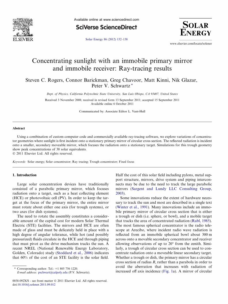
Some innovations reduce the extent of hardware neces-sary to track the sun and most are described in a single text(Winter et al., 1991). Many innovations include an immo-bile primary mirror of circular cross section that is eithera trough or dish (i.e. sphere, or bowl), and a mobile targetthat tracks the area of concentrated radiation (Rabl, 1985).The most famous spherical concentrator is the radio tele-scope at Arecibo, where incident radio wave radiation isreflected from an immobile spherical bowl about 300 macross onto a movable secondary concentrator and receiverallowing observations of up to 20� from the zenith. Simi-larly, a trough of circular cross section can be used to con-centrate radiation onto a moveable linear secondary target.Whether a trough or dish, the primary mirror has a circularcross section of radius R, rather than a parabola in order toavoid the aberration that increases with radiation ofincreased off axis incidence (Fig. 1a). A mirror of circular
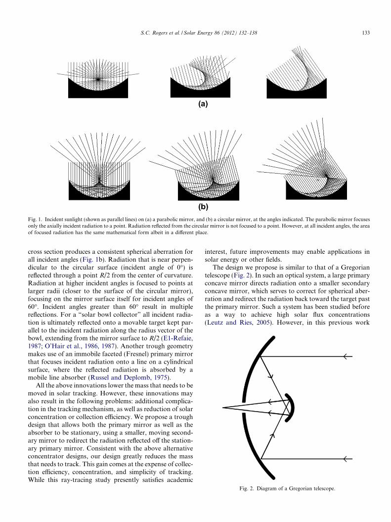
Fig. 1. Incident sunlight (shown as parallel lines) on (a) a parabolic mirror, and (b) a circular mirror, at the angles indicated. The parabolic mirror focusesonly the axially incident radiation to a point. Radiation reflected from the circular mirror is not focused to a point. However, at all incident angles, the areaof focused radiation has the same mathematical form albeit in a different place.
S.C. Rogers et al. / Solar Energy 86 (2012) 132–138 133
cross section produces a consistent spherical aberration forall incident angles (Fig. 1b). Radiation that is near perpen-dicular to the circular surface (incident angle of 0�) isreflected through a point R/2 from the center of curvature.Radiation at higher incident angles is focused to points atlarger radii (closer to the surface of the circular mirror),focusing on the mirror surface itself for incident angles of60�. Incident angles greater than 60� result in multiplereflections. For a “solar bowl collector” all incident radia-tion is ultimately reflected onto a movable target kept par-allel to the incident radiation along the radius vector of thebowl, extending from the mirror surface to R/2 (E1-Refaie,1987; O’Hair et al., 1986, 1987). Another trough geometrymakes use of an immobile faceted (Fresnel) primary mirrorthat focuses incident radiation onto a line on a cylindricalsurface, where the reflected radiation is absorbed by amobile line absorber (Russel and Deplomb, 1975).
All the above innovations lower the mass that needs to bemoved in solar tracking. However, these innovations mayalso result in the following problems: additional complica-tion in the tracking mechanism, as well as reduction of solarconcentration or collection efficiency. We propose a troughdesign that allows both the primary mirror as well as theabsorber to be stationary, using a smaller, moving second-ary mirror to redirect the radiation reflected off the station-ary primary mirror. Consistent with the above alternativeconcentrator designs, our design greatly reduces the massthat needs to track. This gain comes at the expense of collec-tion efficiency, concentration, and simplicity of tracking.While this ray-tracing study presently satisfies academic
interest, future improvements may enable applications insolar energy or other fields.
The design we propose is similar to that of a Gregoriantelescope (Fig. 2). In such an optical system, a large primaryconcave mirror directs radiation onto a smaller secondaryconcave mirror, which serves to correct for spherical aber-ration and redirect the radiation back toward the target pastthe primary mirror. Such a system has been studied beforeas a way to achieve high solar flux concentrations(Leutz and Ries, 2005). However, in this previous work
Fig. 2. Diagram of a Gregorian telescope.
(a) Equinox (b) Summer (c) Winter
N
Fig. 3. Incident radiation is reflected from a stationary primary mirror and focused onto a stationary target by means of a smaller, mobile secondarymirror. For an east–west oriented trough the surface is optimized for equinox, summer and winter sunlight can still be focused onto the same target.
134 S.C. Rogers et al. / Solar Energy 86 (2012) 132–138
the spatial relationship between the target, and primary andsecondary mirrors remains fixed and the entire system mustbe oriented with respect to the incident radiation to main-tain focus. Our proposed concentrator design has boththe primary mirror and target stationary. Focusing isachieved through the movement of the smaller, secondarymirror (Fig. 3). In this paper, we explore the performanceof a linear trough geometry. The same technology canequally be applied to dish geometry.
2. Methodology
Modeling of the shape and placement of reflecting sur-faces was made possible with commercial ray-tracing soft-ware (LightTools 6.3.0 by Optical Research Associates).We used the Solar Tracking Utility included in LightToolsto provide realistic simulations of collector performance atSan Luis Obispo, CA (35.27� N Latitude). The simulatedsun was a uniformly radiant circle of radius 100 m, located21,483 m from the collector, subtending an angle of 0.533�.Modeling was purely geometric: mirrors were assigned areflectivity of 100% and the HCE, a reflectivity of 0%.Troughs are oriented east–west, facing both perfectly
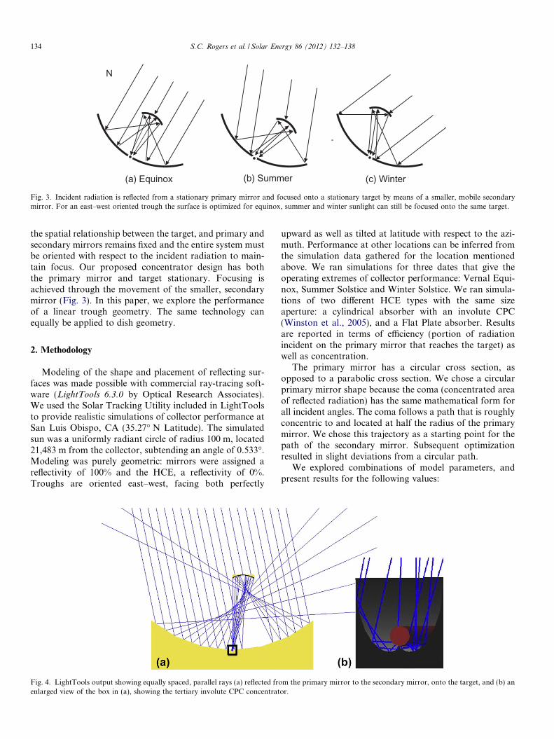
Fig. 4. LightTools output showing equally spaced, parallel rays (a) reflected froenlarged view of the box in (a), showing the tertiary involute CPC concentrat
upward as well as tilted at latitude with respect to the azi-muth. Performance at other locations can be inferred fromthe simulation data gathered for the location mentionedabove. We ran simulations for three dates that give theoperating extremes of collector performance: Vernal Equi-nox, Summer Solstice and Winter Solstice. We ran simula-tions of two different HCE types with the same sizeaperture: a cylindrical absorber with an involute CPC(Winston et al., 2005), and a Flat Plate absorber. Resultsare reported in terms of efficiency (portion of radiationincident on the primary mirror that reaches the target) aswell as concentration.
The primary mirror has a circular cross section, asopposed to a parabolic cross section. We chose a circularprimary mirror shape because the coma (concentrated areaof reflected radiation) has the same mathematical form forall incident angles. The coma follows a path that is roughlyconcentric to and located at half the radius of the primarymirror. We chose this trajectory as a starting point for thepath of the secondary mirror. Subsequent optimizationresulted in slight deviations from a circular path.
We explored combinations of model parameters, andpresent results for the following values:
m the primary mirror to the secondary mirror, onto the target, and (b) anor.
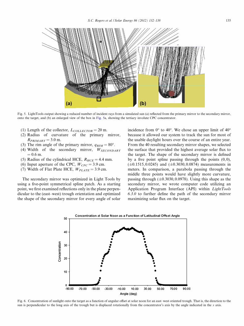
Fig. 5. LightTools output showing a reduced number of incident rays from a simulated sun (a) reflected from the primary mirror to the secondary mirror,onto the target, and (b) an enlarged view of the box in Fig. 5a, showing the tertiary involute CPC concentrator.
S.C. Rogers et al. / Solar Energy 86 (2012) 132–138 135
(1) Length of the collector, LCOLLECTOR = 20 m.(2) Radius of curvature of the primary mirror,
RPRIMARY = 3.0 m.(3) The rim angle of the primary mirror, qRIM = 80�.(4) Width of the secondary mirror, WSECONDARY
= 0.6 m.(5) Radius of the cylindrical HCE, RHCE = 4.4 mm.(6) Input aperture of the CPC, WCPC = 3.9 cm.(7) Width of Flat Plate HCE, WPLATE = 3.9 cm.
The secondary mirror was optimized in Light Tools byusing a five-point symmetrical spline patch. As a startingpoint, we first examined reflections only in the plane perpen-dicular to the (east–west) trough orientation and optimizedthe shape of the secondary mirror for every angle of solar
Fig. 6. Concentration of sunlight onto the target as a function of angular offsetsun is perpendicular to the long axis of the trough but is displaced rotationall
incidence from 0� to 40�. We chose an upper limit of 40�because it allowed our system to track the sun for most ofthe usable daylight hours over the course of an entire year.From the 40 resulting secondary mirror shapes, we selectedthe surface that provided the highest average solar flux tothe target. The shape of the secondary mirror is definedby a five point spline passing through the points (0, 0),(±0.1515,0.0245) and (±0.3030,0.0874) measurements inmeters. In comparison, a parabola passing through themiddle three points would have slightly more curvature,passing through (±0.3030,0.0978). Using this shape as thesecondary mirror, we wrote computer code utilizing anApplication Program Interface (API) within LightTools6.3.0 to further define the path of the secondary mirrormaximizing solar flux on the target.
at solar noon for an east–west oriented trough. That is, the direction to they from the concentrator’s axis by the angle indicated in the x axis.
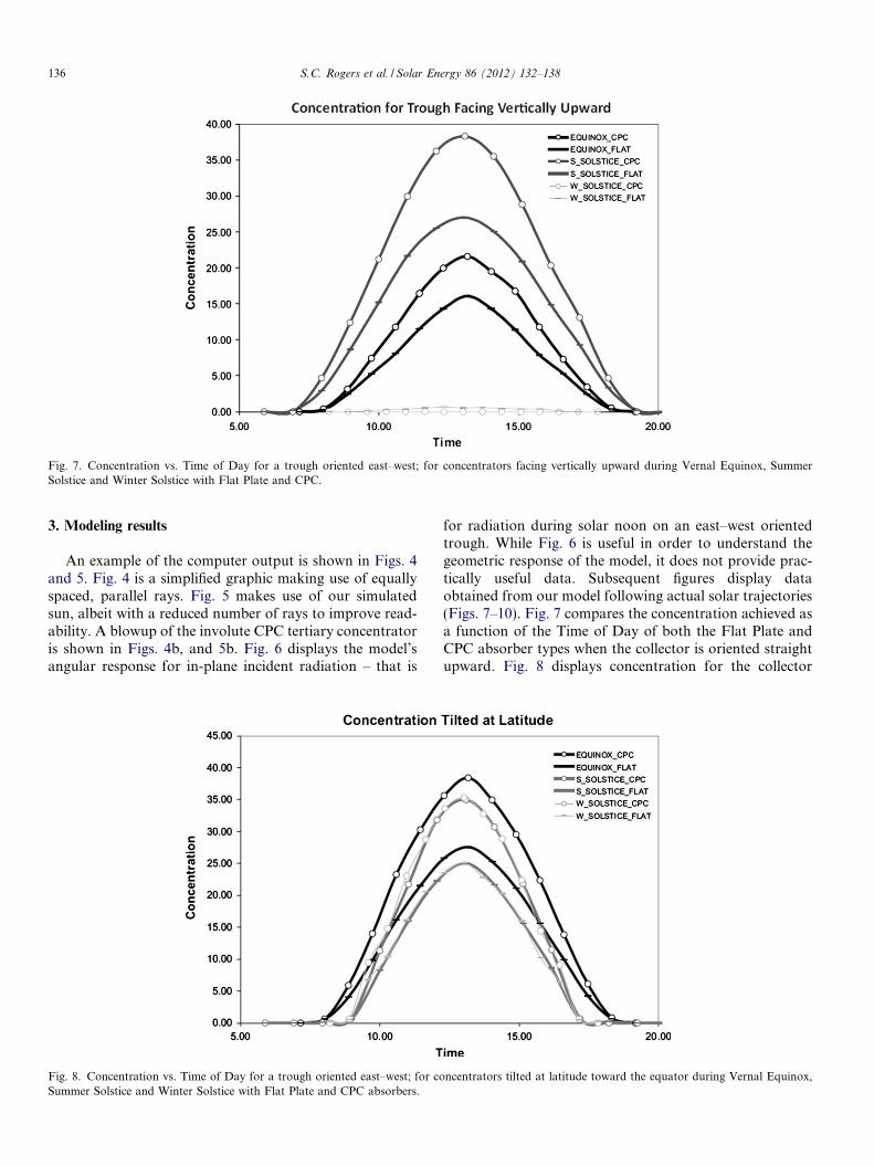
Fig. 7. Concentration vs. Time of Day for a trough oriented east–west; for concentrators facing vertically upward during Vernal Equinox, SummerSolstice and Winter Solstice with Flat Plate and CPC.
136 S.C. Rogers et al. / Solar Energy 86 (2012) 132–138
3. Modeling results
An example of the computer output is shown in Figs. 4and 5. Fig. 4 is a simplified graphic making use of equallyspaced, parallel rays. Fig. 5 makes use of our simulatedsun, albeit with a reduced number of rays to improve read-ability. A blowup of the involute CPC tertiary concentratoris shown in Figs. 4b, and 5b. Fig. 6 displays the model’sangular response for in-plane incident radiation – that is
Fig. 8. Concentration vs. Time of Day for a trough oriented east–west; for coSummer Solstice and Winter Solstice with Flat Plate and CPC absorbers.
for radiation during solar noon on an east–west orientedtrough. While Fig. 6 is useful in order to understand thegeometric response of the model, it does not provide prac-tically useful data. Subsequent figures display dataobtained from our model following actual solar trajectories(Figs. 7–10). Fig. 7 compares the concentration achieved asa function of the Time of Day of both the Flat Plate andCPC absorber types when the collector is oriented straightupward. Fig. 8 displays concentration for the collector
ncentrators tilted at latitude toward the equator during Vernal Equinox,
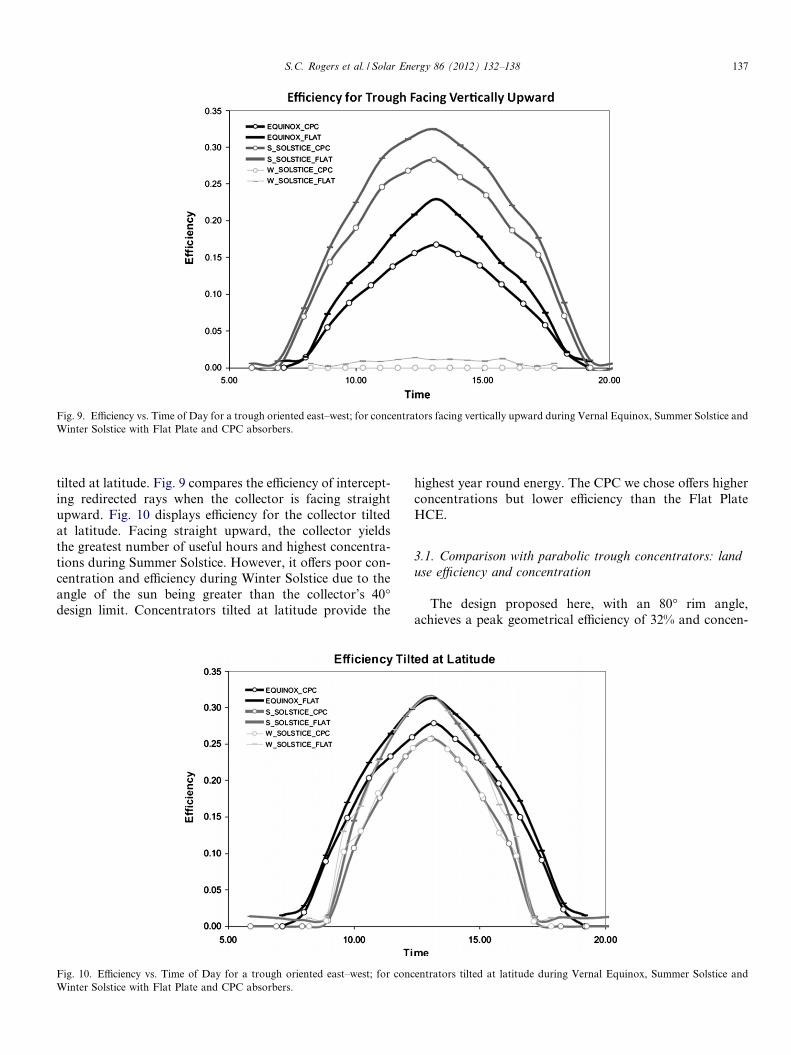
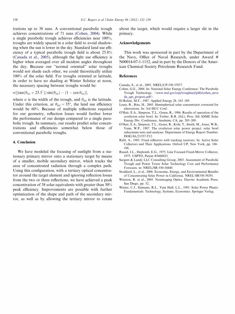
Fig. 9. Efficiency vs. Time of Day for a trough oriented east–west; for concentrators facing vertically upward during Vernal Equinox, Summer Solstice andWinter Solstice with Flat Plate and CPC absorbers.
S.C. Rogers et al. / Solar Energy 86 (2012) 132–138 137
tilted at latitude. Fig. 9 compares the efficiency of intercept-ing redirected rays when the collector is facing straightupward. Fig. 10 displays efficiency for the collector tiltedat latitude. Facing straight upward, the collector yieldsthe greatest number of useful hours and highest concentra-tions during Summer Solstice. However, it offers poor con-centration and efficiency during Winter Solstice due to theangle of the sun being greater than the collector’s 40�design limit. Concentrators tilted at latitude provide the
Fig. 10. Efficiency vs. Time of Day for a trough oriented east–west; for concWinter Solstice with Flat Plate and CPC absorbers.
highest year round energy. The CPC we chose offers higherconcentrations but lower efficiency than the Flat PlateHCE.
3.1. Comparison with parabolic trough concentrators: land
use efficiency and concentration
The design proposed here, with an 80� rim angle,achieves a peak geometrical efficiency of 32% and concen-
entrators tilted at latitude during Vernal Equinox, Summer Solstice and
138 S.C. Rogers et al. / Solar Energy 86 (2012) 132–138
trations up to 38 suns. A conventional parabolic troughachieves concentrations of 71 suns (Cohen, 2004). Whilea single parabolic trough achieves efficiencies near 100%,troughs are widely spaced in a solar field to avoid shadow-ing when the sun is lower in the sky. Standard land use effi-ciency of a typical parabolic trough field is about 25.8%(Canada et al., 2005), although the light use efficiency ishigher when averaged over all incident angles throughoutthe day. Because our “normal oriented” solar troughswould not shade each other, we could theoretically utilize100% of the solar field. For troughs oriented at latitude,in order to have no shading at Winter Solstice at noon,the necessary spacing between troughs would be:
w½ðtanðhlat þ 23:5� ÞÞ sinðhlatÞ � ð1� cos hlatÞ�;
where w is the width of the trough, and hlat is the latitude.Under this criterion, at hlat = 35�, the land use efficiencywould be 60%. Because of multiple reflections requiredfor our geometry, reflection losses would further lowerthe performance of our design compared to a single para-bolic trough. In summary, our results predict solar concen-trations and efficiencies somewhat below those ofconventional parabolic troughs.
4. Conclusion
We have modeled the focusing of sunlight from a sta-tionary primary mirror onto a stationary target by meansof a smaller, mobile secondary mirror, which tracks thearea of concentrated radiation through a complex path.Using this configuration, with a tertiary optical concentra-tor around the target element and ignoring reflection lossesfrom the two or three reflections, we have achieved a peakconcentration of 38 solar equivalents with greater than 30%peak efficiency. Improvements are possible with furtheroptimization of the shape and path of the secondary mir-ror, as well as by allowing the tertiary mirror to rotate
about the target, which would require a larger slit in theprimary.
Acknowledgements
This work was sponsored in part by the Department ofthe Navy, Office of Naval Research, under Award #N00014-07-1-1152, and in part by the Donors of the Amer-ican Chemical Society Petroleum Research Fund.
References
Canada, S., et al., 2005. NREL/CP-550-37077.Cohen, G.E., 2004. In: National Solar Energy Conference: The Parabolic
Trough Technology. <www.nrel.gov/csp/troughnet/pdfs/cohen_nevada_aps_projects.pdf>.
El-Refaie, M.F., 1987. Applied Energy 28, 163–189.Leutz, R., Ries, H., 2005. Hemispherical solar concentrator corrected for
aberrations. In: 3rd ISCC Conf.O’Hair, E.A., Simpson, T.L., Green, R., 1986. Results of operation of the
crosbyton solar bowl. In: Ferber, R.R. (Ed.), Proc. 8th ASME SolarEnergy Div. Conference, Anaheim, CA, pp. 205–209.
O’Hair, E.A., Simpson, T.L., Green, R., Krile, T., Smith, M., Jones, W.B.,Vann, W.P., 1987. The crosbyton solar power project: solar bowlsubsystems tests and analyses. Department of Energy Report Number:DOE/AL/21557-T12.
Rabl, A., 1985. Fixed reflectors with tracking receivers. In: Active SolarCollectors and Their Applications. Oxford UP, New York, pp. 186–188.
Russel, J.L., Deplomb, E.G., 1975. Line Focused Fixed-Mirror Collector,1975. USPTO, Patent #3868823.
Sargent & Lundy LLC Consulting Group, 2003. Assessment of ParabolicTrough and Power Tower Solar Technology Cost and PerformanceForecasts. in: NREL/SR-550-34440.
Stoddard, L., et al., 2006. Economic, Energy, and Environmental Benefitsof Concentrating Solar Power in California. NREL-SR550-39291.
Winston, R. et al., 2005. Nonimaging Optics. Elsevier Academic Press,San Diego, pp. 52.
Winter, C.J., Sizmann, R.L., Vant Hull, L.L., 1991. Solar Power Plants:Fundamentals: Technology, Systems, Economics. Springer Verlag.