con2
40
CONSULTATION VERSION 0.1 The Electricity Wiring Regulations 2007 APPENDICES - page 1 of 40 APPENDICES A1. Glossary of Terms & Abbreviations ................................................................... 2 A2. List of Clauses in the Regulations which do not apply to Old Installations ....... 3 A3. Reference Standards ......................................................................................... 4 A4. Guidance Note on Supply Voltage Changes ..................................................... 5 A5. Guidance Notes for the Estimation of Diversified Connected Load ................... 5 A6. Customer Earthed (TT) and Distribution Company Earthed Systems (TN-S) . 5 A7. Guidance Note on Principles of Electric Shock Protection and Earthing .......... 5 A8. Guidance Note on Earth Conductors and Equipotential Bonding ...................... 5 A9. Electric Shock Protection Using Residual Current Devices ............................... 5 A10. Performance Characteristics for MCBs complying with BS EN 60898 ............. 5 A11. Sizing of Earth Conductors and Equipotential Bonding Conductors ................ 5 A12. Number of Earth Electrodes Required for Installations ...................................... 5 A13. Mandatory Connections to Earth Conductors .................................................... 5 A14. Earth Leakage Protection for Equipment ........................................................... 5 A15. Earth Fault Loop Impedance.............................................................................. 5 A16. Cable Ratings, Voltage Drop and Ambient Temperature Correction Factors ... 5 A17. Colour Identification of Cables ........................................................................... 5 A18. Capacity of Conduits and Trunking .................................................................... 5 A19. IP Coding for Ingress Protection ........................................................................ 5 A20. Standard Wiring Diagram Symbols .................................................................... 5 A21. Typical Layout for Supply Intake Room ............................................................. 5 A22. Typical Layout for Ring Circuits ......................................................................... 5 A23. Approved and Prohibited Plugs and Socket Types............................................ 5 A24. Minimum Recommended Number of Socket Outlets ......................................... 5 A25. Method for Measuring Earth Resistance............................................................ 5 A26. Method for Earth Loop Impedance Test ............................................................ 5 A27. Method for Continuity Tests ............................................................................... 5 A28. Method for Insulation Resistance Test............................................................... 5 A29. Method for Polarity Tests ................................................................................... 5 A30. Installation Certificate......................................................................................... 5 A31. Inspection Report ............................................................................................... 5 A32. Testing Report ................................................................................................... 5 A33. Load Distribution Schedule ................................................................................ 5
-
Upload
abdullah-ibrahim -
Category
Documents
-
view
8 -
download
1
Transcript of con2

CONSULTATION VERSION 0.1
The Electricity Wiring Regulations 2007 APPENDICES - page 1 of 40
APPENDICES
A1. Glossary of Terms & Abbreviations ................................................................... 2 A2. List of Clauses in the Regulations which do not apply to Old Installations ....... 3 A3. Reference Standards......................................................................................... 4 A4. Guidance Note on Supply Voltage Changes ..................................................... 5 A5. Guidance Notes for the Estimation of Diversified Connected Load................... 5 A6. Customer Earthed (TT) and Distribution Company Earthed Systems (TN-S) . 5 A7. Guidance Note on Principles of Electric Shock Protection and Earthing.......... 5 A8. Guidance Note on Earth Conductors and Equipotential Bonding ...................... 5 A9. Electric Shock Protection Using Residual Current Devices ............................... 5 A10. Performance Characteristics for MCBs complying with BS EN 60898 ............. 5 A11. Sizing of Earth Conductors and Equipotential Bonding Conductors................ 5 A12. Number of Earth Electrodes Required for Installations...................................... 5 A13. Mandatory Connections to Earth Conductors .................................................... 5 A14. Earth Leakage Protection for Equipment ........................................................... 5 A15. Earth Fault Loop Impedance.............................................................................. 5 A16. Cable Ratings, Voltage Drop and Ambient Temperature Correction Factors ... 5 A17. Colour Identification of Cables........................................................................... 5 A18. Capacity of Conduits and Trunking.................................................................... 5 A19. IP Coding for Ingress Protection........................................................................ 5 A20. Standard Wiring Diagram Symbols.................................................................... 5 A21. Typical Layout for Supply Intake Room ............................................................. 5 A22. Typical Layout for Ring Circuits ......................................................................... 5 A23. Approved and Prohibited Plugs and Socket Types............................................ 5 A24. Minimum Recommended Number of Socket Outlets......................................... 5 A25. Method for Measuring Earth Resistance............................................................ 5 A26. Method for Earth Loop Impedance Test ............................................................ 5 A27. Method for Continuity Tests ............................................................................... 5 A28. Method for Insulation Resistance Test............................................................... 5 A29. Method for Polarity Tests ................................................................................... 5 A30. Installation Certificate......................................................................................... 5 A31. Inspection Report............................................................................................... 5 A32. Testing Report ................................................................................................... 5 A33. Load Distribution Schedule ................................................................................ 5

CONSULTATION VERSION 0.1
The Electricity Wiring Regulations 2007 APPENDICES - page 2 of 40
A1. Glossary of Terms & Abbreviations
A.C alternating current D.C. direct current RCD residual current device RCCB residual current circuit breaker RCBO residual current breaker (with) overcurrent ELCB earth leakage circuit breaker MCB miniature circuit breaker MCCB moulded case circuit breaker SDB sub distribution board MDB main distribution board TT a three phase and locally earthed system TN-S a three phase system, with neutral earthing a the distribution transformer, and having
separate neutral and phase conductors in the supply cable ESMA Emirates Standardisation & Metrology Authority BS British Standard IEC International Electrotechnical Commission EN European Normalisation standard document BS-EN British Standard which has been accepted under the European Normalisation procedure

CONSULTATION VERSION 0.1
The Electricity Wiring Regulations 2007 APPENDICES - page 3 of 40
A2. List of Clauses in the Regulations which
do not apply to Old Installations The Electricity Wiring Regulations are effective from 1 March 2007 [proposed]. For any Installations which were completed before this date the following clauses of the Regulations do not apply or will apply after 1 January 2010 or, if earlier, at the time of the next inspection or re-certification.
Clause
Reason / Comment Application
1.4.4 General requirement for compliance of all equipment and materials to international standards
Does not apply retrospectively
1.6.7, 4.4.1 and 4.4.6
Requirement for overall earth leakage protection
Must apply by 1 January 2010
1.6.12, 1.6.13 Requirement for labelling of parts of the Installation
Must apply by 1 January 2010
4.2.2 Prohibition of fused cut-outs Must apply by 1 January 2010
5.2.5 Requirement for maximum Customer Earth Electrode impedance
Must apply by 1 January 2010
5.5.1 Requirement for Equipotential Bonding Conductors
Must apply by 1 January 2010

CONSULTATION VERSION 0.1
The Electricity Wiring Regulations 2007 APPENDICES - page 4 of 40
A3. Reference Standards
The table below shows the reference standards that may be used for the main components required for Electrical Installations. Additional standards not listed may be referenced from the UK Wiring Regulations (BS7671: 2001) or other international standards, with agreement of the relevant Distribution Company providing supply.
Item BS IEC
Cables PVC insulation (thermoplastic) - for power & lighting
6004, 6346 502
PVC insulation (thermoplastic) - for switchgear & control wiring
6231 227
Rubber insulation (thermosetting) 5467, 6234, 7211 Mineral insulation 6207, 6081 702 Flexible cables & cords 6500, 6141, 6004, 6977 227, 245 Cable glands 6121
Conduits Steel PVC Flexible Steel
4568, 60423*, 50086*, 31 4607, 6053, 6099 731
432, 614 423
Degrees of Protection & Ingress 60529* 529 Distribution Assemblies for Construction Sites
4363
364-7-704
Earthing 7430, 951 364-5-54 Electrical Accessories
General 5733 Ceiling roses 67 Cooker Control Units 4177 Plugs & Socket Outlets 546, 196, 1363, 4343 Switches 3676, 60947-3*
Emergency Lighting 5266 Hazardous Areas 5345, 5501 Household Appliances 3456, 60335* Isolating Transformer (for shaver sockets) 3535
LV Switchgear & Assemblies General 60439*, 60947*, 60947-1* 947, 439-1 & 3 Circuit Breakers (MCB, MCCB) 60898, 3871 898 Earth Leakage Circuit Breakers (ELCB, RCD)
4293 755
Fuses 88, 1361 Busbar trunking systems 60439-2 439-2 Neon Signs 559
Non Combustibility Test 476 Trunking, Ducting and Fittings 4678 1084 Thermal Classification of Electrical Insulation
2757 85
* Also listed as EN (European) Standard under the same number

CONSULTATION VERSION 0.1
The Electricity Wiring Regulations 2007 APPENDICES - page 5 of 40
A4. Guidance Note on Supply Voltage Changes Distribution Companies in the UAE have traditionally based the design of their networks on the UK power system. Previously, the voltage of supply was declared to be 240V single-phase or 415V three phase, with an allowed variation in the supply of +/- 6%. However, with the harmonization of supply voltages in Europe (line with IEC 38) the UK has adopted a supply voltage of 230V / 400V +/- 10%. Distribution Companies in the UAE have now followed the same change but as with companies in the UK they are expected to continue to operate their networks in the old operating range for a transition period (1 or 2 years). This can be achieved by declaring a supply voltage of 230V/400V +/- 10% but in practice operating the LV networks in a range of 230V/400V +10% to -6%. This means that existing equipment and appliances will not experience any significant change in the maximum supply voltage and only a small change in the minimum supply voltage (see illustration below). However, new equipment and appliances must be designed to operate in the wider range of 230V/400V +/- 10%. At the end of the transition period Distribution Companies are expected to switch to the wider range which allows for a single phase voltage level down to 207V (i.e. 230V - 10%), which allowing for a 4% volt drop within a customers premises means that an appliance could receive a voltage as low as 198.7V and must continue to operate satisfactorily. Figure A4 Comparison of old and new supply voltage ranges
240 254.4225.6
210 220 230 240 250 260200
230 253.0216.2
- 6% +10%
230 253.0207.0
- 6% +6%
- 10% +10%
Volts
IEC.38 supply voltage range as adopted in the Supply Regulations for Abu Dhabi
Old UK supply voltage rangepreviously used in Abu Dhabi
IEC.38 voltage operated under a restrictedrange by Distribution Companies (transition period)

CONSULTATION VERSION 0.1
The Electricity Wiring Regulations 2007 APPENDICES - page 6 of 40
A5. Guidance Notes for the Estimation of Diversified Connected Load The total estimated load at a Premise must be calculated and submitted to the Distribution Company in order to make an application for a new supply of electricity or alteration of an existing supply. It is normal practice to calculate the ‘Diversified Connected Load’ rather than simply take the sum of all equipment and appliances in the Installation. This method avoids over sizing of the Installation as well as the Distribution Company supply. Firstly, the design and layout of an installation should be detailed in the format of load distribution schedules as shown in appendix A33. These schedules should list all connection points and fixed Appliances in each circuit. To arrive at the total ‘Diversified Connected Load’, assume the following: (a) Lighting: sum of wattage of all luminaries OR assume 100W for each lighting point and / or 1.8 x lamp wattage for fluorescent lighting (b) 13A power points: assume 200 watts per point for general ring circuits (except kitchen) assume 3000 watts for fixed kitchen appliances (washing machine etc)
kitchen worktop points - assume 1000W (c) other power points: kitchen cooker – take rating of circuit or appliance air conditioning supply points – taking rating of each a/c unit water heater points – take rating of each unit lifts and other motors – take rating of each unit Diversity factors may be applied to sub-totals of the above categories as follows, before taking the grand total as the Diversified Connected Load: (a) total lighting: 80% (b) total 13 general power points: 70% (c) total other power points: no diversity For non domestic premises the above rules and diversity factors will need to be adapted to take into account the particular nature of the installation. This should be done by a qualified designer or engineer. For example, the connected load of industrial machinery in continuous operation would be taken as 100% unless it was mainly in night time operation, or had very short (few minutes) load cycles. Another example could be a warehouse with automatic motion operated lighting for energy saving, which may result in a diversity factor as low as 20%. Alternatively, the average load per m2 of floor area can be used if such data is available from other similar premises.

CONSULTATION VERSION 0.1
The Electricity Wiring Regulations 2007 APPENDICES - page 7 of 40
A6. Customer Earthed (TT) and Distribution Company Earthed Systems (TN-S)
Figure A6 (a) Customer Earthed System (TT) Figure A6 (b) Distribution Company Earthed System (TN-S)
L1
L2L3
N
Customer’sMain
DistributionBoardCustomer’s
Main EarthTerminal
E
N
L
E
Appliance Earth
Distribution Company Transformer
TransformerNeutral Point Earth
Earthfault
Earth faultcurrent
Customer’sEarth
Electrode
L1
L2L3
N
Customer’sMain
DistributionBoard
Customer’sMain EarthTerminal
E
N
L
E
Appliance Earth
Distribution Company Transformer
Earth sheath or armour of Distribution Company Cable
TransformerNeutral Point Earth
Earthfault
Earth fault current
L1
L2L3
N
Customer’sMain
DistributionBoard
Customer’sMain EarthTerminal
E
N
L
E
Appliance Earth
Distribution Company Transformer
Earth sheath or armour of Distribution Company Cable
TransformerNeutral Point Earth
Earthfault
Earth fault current

CONSULTATION VERSION 0.1
The Electricity Wiring Regulations 2007 APPENDICES - page 8 of 40
A7. Guidance Note on Principles of Electric Shock Protection and Earthing
The Regulations include requirements which are designed to protect persons against electric shock in situations of both Direct and Indirect Contact with electrical voltages. Direct Contact is defined as the inadvertent or accidental contact with a live phase conductor (or neutral conductor that is connected through a load to a live conductor). The term Indirect Contact refers to situations where a person is touching an Earthed Metallic Part of an Appliance, Installation, or other Extraneous Metallic Part which then becomes live (for a short time) due to the passage of earth fault current. Such metallic parts could include the casing or cover of an Appliance such as a fridge or washing machine, the earthed parts of an Installation such as earthed metal conduits, metallic switches or socket outlets, or other Extraneous Metallic Parts in a building which have been earthed, such as metal pipes. (a) Direct Contact: The risk of persons coming into contact directly with live phase conductors is mitigated against in the following ways:
(i) insulation of conductors (basic insulation) (ii) double insulation of conductors (Class II Appliances) (iii) secure enclosures, barriers or covers on all un-insulated parts (e.g. connection
terminals, busbar sections etc) (iv) reduced voltage systems (SELV) (v) isolated (unearthed) systems (e.g. BS3535 ‘shaver socket’ isolating transformer) (vi) limitation of contact time and current by use of a Residual Current Device
The requirement for all occupied Premises to have overall earth leakage protection is new to these Regulations. Previously, there was no provision for Protective Devices which could give protection against Direct Contact with a live conductor. Note: overcurrent devices such as MCBs do not give protection against electric shock. In addition, RCDs do not give protection against electric shock between phase conductors or between phase conductors and earth, although this would be a rare occurrence. (b) Indirect Contact: Indirect Contact, through Earthed metallic parts, is mitigated against by:
(i) ensuring that the voltage rise on earthed metal parts during the passage of fault current is kept below a safe level (deemed to be 50V)
(ii) ensuring that persons cannot be in contact with any two metallic parts which are at a different potential during the passage of earth fault current
(iii) ensuring that a ‘high resistance’ earth fault does not persist and is cleared by operation of earth leakage protection
The diagram over leaf illustrates cases of Direct and Indirect Contact

CONSULTATION VERSION 0.1
The Electricity Wiring Regulations 2007 APPENDICES - page 9 of 40
Figure A7 Cases of Direct and Indirect Contact which may lead to Electric Shock
1 – Direct Contact with live conductor 2 – Contact with external metallic part of Appliance during earth fault 3 – Contact with earthed metallic part of Electrical Installation during earth fault 4 – Contact between extraneous metallic part and earthed metallic part Note: Installations must be designed to keep the voltage rise on earthed metallic parts below 50V during the time of fault
Customer’sMain
DistributionBoard
Customer’sMain EarthTerminal
ApplianceEarth fault
Earth faultcurrent
Customer’sEarth Electrode (for TT system)
Connection to earthsheath of Distribution
Company’s cable(TN-S system)
L1L2L3N
RCD
N LE11
2
33
44
CONSULTATION VERSION 0.1
The Electricity Wiring Regulations 2007 APPENDICES - page 10 of 40
A8. Guidance Note on Earth Conductors and Equipotential Bonding
Earth Conductors Earth Conductors within Installations are a vital link for safety. They provide a path for current from a faulty line touching Extraneous Metallic Parts in a premises, or touching Exposed Metallic Parts of an Appliance to flow to Earth and back to the earthed neutral of the distribution transformer. Such earth currents can include short circuits, high resistance faults, as well as current flow due to Direct Contact with persons. The term ‘Earth Conductor’ covers all of the following: ‘main’ Earth Conductors: - conductors from Earth Electrodes to the Main Earth Terminal - conductors from the Main Earth Terminal to Distribution Boards ‘circuit’ Earth Conductors: - conductors from Distribution Boards to Final Circuits and Appliance
connection points (also known as circuit Earth Conductors) ’appliance’ Earth Conductors: - conductors from Appliance connection points (e.g. 3 pin socket outlets)
to an Appliance, normally within a sheathed cable or flex - conductors connecting Exposed Metallic Parts within an Appliance Other terminology which is confusingly used outside these Regulations includes: ‘circuit protective conductor’ (CPC), ‘earth continuity conductor’ (ECC), or ‘earth wire’. The main Earth Conductors in an installation are very important, since they provide the only route to the Main Earth Terminal or Earth Electrodes, and therefore must be safeguarded against damage, corrosion, accidental disconnection etc. They should be subject to regular inspection and testing. Connections to the Main Earth Terminal and Earth Electrodes should have a standard warning label as shown below:
Figure A8(a) Standard Safety Label for main Earth connections Equipotential Bonding Conductors The purpose of Equipotential Bonding Conductors is to prevent the rise of dangerous voltage on extraneous metallic parts in a premises which may be touched by persons during the instant of a fault occurring. In addition, Equipotential Bonding is a safeguard in the unlikely event of loss of the main earth connection (either Customer Earth or Distribution Company Earth) whereby all metallic parts in a premises are kept at the same voltage, even if there is a rise of voltage above zero (assuming that any persons inside a building cannot touch the physical Earth outside the premises). ‘Main’ Equipotential Bonding Conductors are used to connect major metallic parts such as water pipes and other underground services that enter a building, see figure A8 (e) over leaf. ‘Supplementary’ Equipotential Bonding Conductors are used to connect metal items in a premises that are in ‘high risk’ areas such as bathrooms, kitchens, semi-outdoor locations (e.g. garage). These locations are similar in that persons may be in contact with water or moisture when touching an earthed ‘extraneous’ metallic part such as a water tap or pipe. Supplementary Equipotential Bonding conductors are connected to the nearest circuit Earth Conductor or main Earth Conductor rather than back to the Main Earth Terminal, see figure A8 (d) over leaf. Supplementary Bonding conductors are not required for standalone items which are not near to any electrical wiring, such as metal doors (unless part of the Electrical Installation), windows, small parts such as handles, brackets etc. As a
““SSAAFFEETTYY EEAARRTTHH CCOONNNNEECCTTIIOONN -- DDOO NNOOTT RREEMMOOVVEE””

CONSULTATION VERSION 0.1
The Electricity Wiring Regulations 2007 APPENDICES - page 11 of 40
main Earth Conductor
customer’s Earth Electrode
label at connection clamp
letters at least 5mm height SAFETY EARTH CONNECTION
- DO NOT REMOVE
inspection pit
general rule, metal parts which are not near to electrical wiring and which have a resistance to earth of 50 k ohms or greater, need not be connected to Equipotential Bonding. The standard sizing of Earth Conductors and Equipotential Bonding Conductors is given in appendix A11. Figure A8 (b) Types of Earth Conductors Figure A8 (c) Connection of Main Earth Conductor to Earth Electrode
circuit Earth Conductorin Appliance flexible cord
circuit Earth Conductorin Ring Circuit
circuit Earth Conductors to accessories (even if plastic)
circuit Earth Conductorsalongside phase and neutral conductors
Fixed appliances
main Earth ConductorMain EarthTerminal
EarthBar

CONSULTATION VERSION 0.1
The Electricity Wiring Regulations 2007 APPENDICES - page 12 of 40
Figure A8 (d) Connection of ‘supplementary’ Equipotential Bonding Conductors Figure A8 (e) Connection of ‘main’ Equipotential Bonding Conductors
supplementary Equipotential Bonding Conductor
SAFETY EARTH CONNECTION- DO NOT REMOVE
label
circuit Earth Conductors
customers MainEarth Terminal
incoming electricity supply (TN-S Earth System)
main EarthConductors
SAFETY EARTH CONNECTION- DO NOT REMOVE
label
if lower section of pipe is insulated connectmain Bonding Conductor at B rather than A

CONSULTATION VERSION 0.1
The Electricity Wiring Regulations 2007 APPENDICES - page 13 of 40
A9. Electric Shock Protection Using Residual Current Devices The Regulations include a compulsory requirement for the provision of overall earth leakage protection, normally using an RCD, for any occupied Premises. Such devices must conform to the performance characteristics specified in BS4293, which requires that a device must operate within 40 milliseconds at 5 times the nominal operating current, and should not operate at less than 50% of its nominal operating current. The performance characteristic of RCD devices is designed so as to reduce the risk of harmful electric shock to persons, either due to Direct Contact with a live conductor or due to Indirect Contact through the earthing of an Installation, Appliance, or Extraneous metallic part in a Premises. The risk to the human body depends on the time and magnitude of current that may pass at the time of an electric shock incident. The ‘low risk’ and ‘high risk’ range of current against time is illustrated below, along with the operating times of typical RCD devices (from IEC60479). Figure A9(a) Time/current response of human body to Electric Shock, vs. RCD characteristics
Response of human body: Zone 1: usually no reaction Zone 2: shock sensation, but usually no harmful effects Zone 3: likelihood of muscular contraction, and temporary cardiac arrest without ventricular
fibrillation Zone 4: in addition to the effects of zone 3, the probability of ventricular fibrillation is increased by
5% for curve C2 and 50% for curve C3; harmful effects such as cardiac arrest, breathing arrest and burns are likely to occur

CONSULTATION VERSION 0.1
The Electricity Wiring Regulations 2007 APPENDICES - page 14 of 40
Figure A9(b) Illustration of operation of RCD devices (3 phase and 1 phase)
Figure A9(c) DC sensing RCDs Due to the use of semiconductors devices in an Installation there may be situations when an earth fault current is not purely sinusoidal but contains a dc or ‘chopped’ waveform. This may de-sensitise or disable standard AC operated RCDs. Special devices are available which are designed to continue to function even for non-sinusoidal supply waveforms (complying with IEC1008, IEC1009). The following symbols are shown on RCDs along with the nominal trip current rating.

CONSULTATION VERSION 0.1
The Electricity Wiring Regulations 2007 APPENDICES - page 15 of 40
A10. Performance Characteristics for MCBs complying with BS EN 60898
Figure A10(a) Current limiting performance data
CONSULTATION VERSION 0.1
The Electricity Wiring Regulations 2007 APPENDICES - page 16 of 40
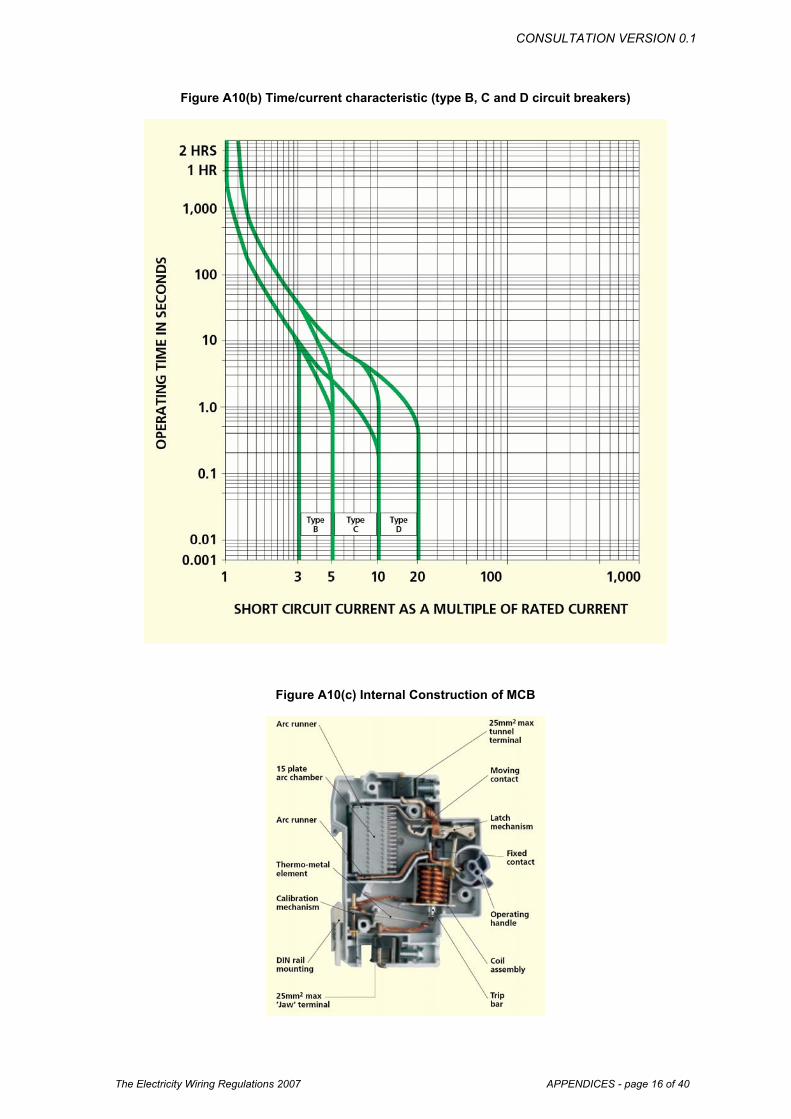
Figure A10(b) Time/current characteristic (type B, C and D circuit breakers)
Figure A10(c) Internal Construction of MCB

CONSULTATION VERSION 0.1
The Electricity Wiring Regulations 2007 APPENDICES - page 17 of 40
A11. Sizing of Earth Conductors and Equipotential Bonding Conductors
Cross Sectional Area of Phase and Neutral
conductors (S)
Minimum Cross Sectional Area of Earth Conductors
Minimum Cross Sectional Area of Equipotential Bonding Conductors
S <= 16mm2 S (not less than 2.5mm2
– see note 2)
S / 2 (not less than 4 or 6mm2
– see note 3)
16 mm2 < S <= 35 mm2 16 mm2 10 mm2
S > 35 mm2 S / 2 S / 4 (but not exceeding 25mm2)
All sizes shown in mm2
Note 1: For main Earth Conductors between Earth Electrodes and the Main Earth
Terminal of an Installation, S should be taken as the cross sectional area of the conductors of the incoming supply cable. For other Earth Conductors S should be taken as the cross section of the circuit phase conductors.
Note 2: Earth Conductors should always be insulated and a cross section of less than 2.5mm should not be used unless they are an integral part of a cable (e.g. an Appliance flexible cord)
Note 3: Main Equipotential Bonding conductors should be sized according to the live conductors of the incoming supply, but should not be less than a minimum size of 6mm2. Supplementary Bonding Conductors should be sized according to the live conductors of the circuit to which they are connected but should not be less than 4mm2.
Note 4: As an alternative to using the above selection table the sizing of Earth Conductors and Equipotential Bonding Conductors may be calculated using the adiabatic equation provided in the UK IEE Wiring Regulations BS7671:2001 paragraph 543-01-03.

CONSULTATION VERSION 0.1
The Electricity Wiring Regulations 2007 APPENDICES - page 18 of 40
A12. Number of Earth Electrodes Required for Installations The number of Earth Electrodes required at a Premises will be determined primarily by the value of Earth Resistance that can be achieved from each. However, the minimum number in any case shall be as shown below:
Main Incoming Circuit Breaker Rating (Amps)
Minimum Number of Earth Electrodes
Minimum size of Earth Conductors
60/100 1 16
200 1 50 300 1 50 400 1 70 500 2 70
600 2 70 800 2 70
1000 2 70
1600 2 70
2000 2 150 2500 2 150
CONSULTATION VERSION 0.1
The Electricity Wiring Regulations 2007 APPENDICES - page 19 of 40
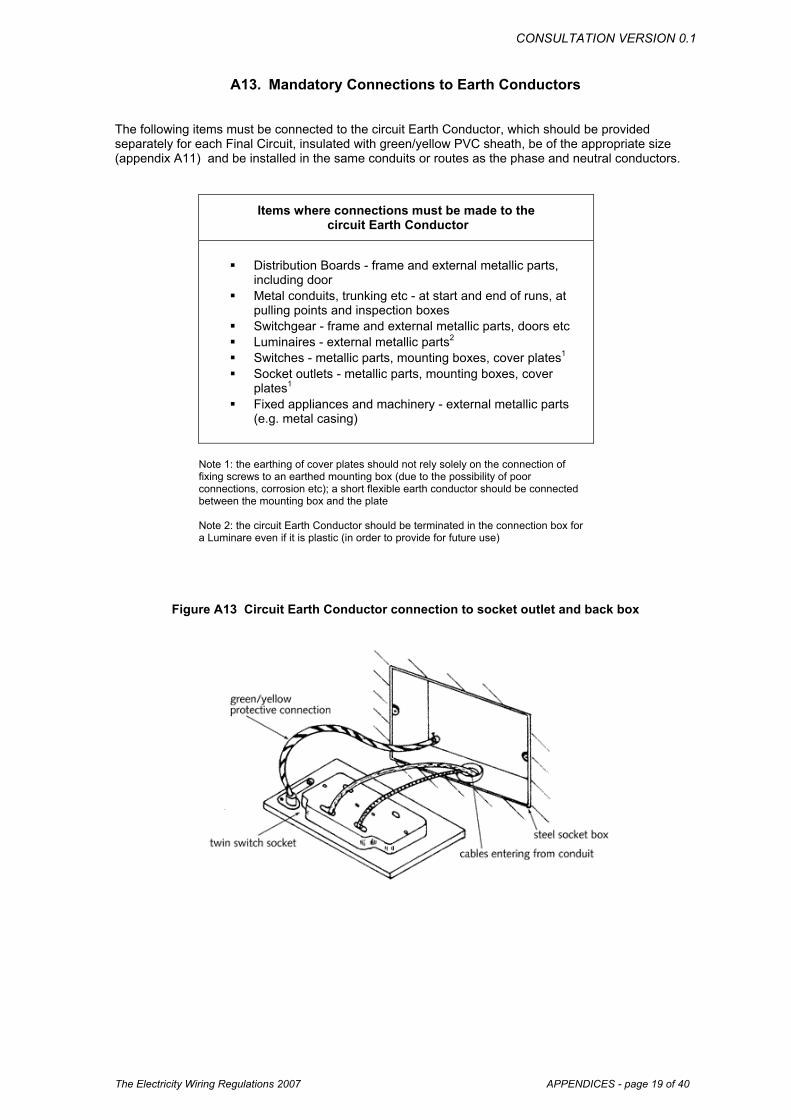
A13. Mandatory Connections to Earth Conductors The following items must be connected to the circuit Earth Conductor, which should be provided separately for each Final Circuit, insulated with green/yellow PVC sheath, be of the appropriate size (appendix A11) and be installed in the same conduits or routes as the phase and neutral conductors.
Items where connections must be made to the circuit Earth Conductor
Distribution Boards - frame and external metallic parts,
including door Metal conduits, trunking etc - at start and end of runs, at
pulling points and inspection boxes Switchgear - frame and external metallic parts, doors etc Luminaires - external metallic parts2 Switches - metallic parts, mounting boxes, cover plates1 Socket outlets - metallic parts, mounting boxes, cover
plates1 Fixed appliances and machinery - external metallic parts
(e.g. metal casing)
Note 1: the earthing of cover plates should not rely solely on the connection of fixing screws to an earthed mounting box (due to the possibility of poor connections, corrosion etc); a short flexible earth conductor should be connected between the mounting box and the plate Note 2: the circuit Earth Conductor should be terminated in the connection box for a Luminare even if it is plastic (in order to provide for future use)
Figure A13 Circuit Earth Conductor connection to socket outlet and back box
CONSULTATION VERSION 0.1
The Electricity Wiring Regulations 2007 APPENDICES - page 20 of 40
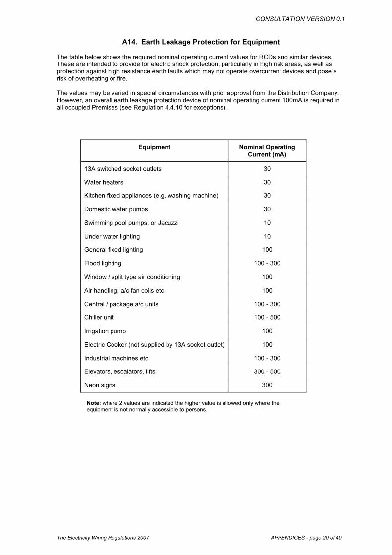
A14. Earth Leakage Protection for Equipment The table below shows the required nominal operating current values for RCDs and similar devices. These are intended to provide for electric shock protection, particularly in high risk areas, as well as protection against high resistance earth faults which may not operate overcurrent devices and pose a risk of overheating or fire. The values may be varied in special circumstances with prior approval from the Distribution Company. However, an overall earth leakage protection device of nominal operating current 100mA is required in all occupied Premises (see Regulation 4.4.10 for exceptions).
Equipment Nominal Operating Current (mA)
13A switched socket outlets 30
Water heaters 30
Kitchen fixed appliances (e.g. washing machine) 30
Domestic water pumps 30
Swimming pool pumps, or Jacuzzi 10
Under water lighting 10
General fixed lighting 100
Flood lighting 100 - 300
Window / split type air conditioning 100
Air handling, a/c fan coils etc 100
Central / package a/c units 100 - 300
Chiller unit 100 - 500
Irrigation pump 100
Electric Cooker (not supplied by 13A socket outlet) 100
Industrial machines etc 100 - 300
Elevators, escalators, lifts 300 - 500
Neon signs 300
Note: where 2 values are indicated the higher value is allowed only where the equipment is not normally accessible to persons.

CONSULTATION VERSION 0.1
The Electricity Wiring Regulations 2007 APPENDICES - page 21 of 40
A15. Earth Fault Loop Impedance Table A15(a) Maximum Earth Fault Loop Impedance for circuits connected by MCBs to give a
disconnection time within 0.4 seconds
- Maximum earth-fault loop impedance (Ohms)
Device rating
(A)
MCB type 1
MCB type 2
MCB type 3
and type C
MCB type B
MCB type D
5 12.00 6.86 4.80 - 2.40 6 10.00 5.71 4.00 8.00 2.00 10 6.00 3.43 2.40 4.80 1.20 15 4.00 2.29 1.60 - 0.80 16 3.75 2.14 1.50 3.00 0.75 20 3.00 1.71 1.20 2.40 0.60 25 2.40 1.37 0.96 1.92 0.48 30 2.00 1.14 0.80 - 0.40 32 1.88 1.07 0.75 1.50 0.38 40 1.5 0.86 0.60 1.20 0.30
Table A15(b) Resistance per metre of copper conductors for calculation of R1 + R2
Conductor cross-sectional area (mm²)
Resistance per metre run (m ohms / m)
1.0 18.1 1.5 12.10 2.5 7.41 4.0 4.61 6.0 3.08 10.0 1.83 16.0 1.15 25.0 0.727
Note: to allow for the increase in resistance with increased temperature under fault conditions these values must be multiplied by 1.2 for p.v.c. insulated cables

CONSULTATION VERSION 0.1
The Electricity Wiring Regulations 2007 APPENDICES - page 22 of 40
Figure A15(a) Formula for Earth Fault loop Impedance
Zs = Ze + ZR1 + R2
Where:
Zs = total Earth Fault Loop Impedance
Ze = Distribution Company supply impedance
ZR1 + R2 = impedance of the longest circuit in the Installation, taken by measuring a circuit phase conductor impedance R1, and the same circuit’s Earthing Conductor impedance R2.
Figure A15(b) Illustration of Component Parts of Earth Fault loop Impedance
l. - the phase conductor from the transformer to the installation 2 -the protective device(s) in the installation 3 -the installation phase conductors from the intake position to the fault 4. - the fault itself (usually assumed to have zero impedance) 5. - the circuit earth conductors 6. - the main earthing terminal 7. - the main earthing conductor 8. - the installation earth electrode 9. - the general mass of earth 10. - the Distribution Company's transformer earth electrode 11. - the Distribution Company's main earthing conductor 12. -the secondary winding of the Distribution Company's transformer

CONSULTATION VERSION 0.1
The Electricity Wiring Regulations 2007 APPENDICES - page 23 of 40
A16. Cable Ratings, Voltage Drop and Ambient Temperature Correction Factors
Table A16(a) Standard cable ratings and Voltage drop for single core, PVC (thermoplastic), non-
armoured, stranded copper conductor (BS6004 and BS6346), with or without sheath, installed in concealed or surface conduit.
Cross sectional
area
In conduit in thermal
insulation
In conduit in thermal insulation
In conduit on wall
In conduit on wall
Volt drop
Volt drop
(mm²) (A) (A) (A) (A) (mV/A/m) (mV/A/m)
- 2 cables 3 or 4 cables
2 cables
3 or 4 cables
2 cables 3 or 4 cables
1.0 11.0 10.5 13.5 12.0 44.0 38.0
1.5 14.5 13.5 17.5 15.5 29.0 25.0
2.5 19.5 18.0 24.0 21.0 18..0 15.0
4.0 26.0 24.0 32.0 28.0 11.0 9.5
6.0 34.0 31.0 41.0 36.0 7.3 6.4
10.0 46.0 42.0 57.0 50.0 4.4 3.8
16.0 61.0 56.0 76.0 68.0 2.8 2.4
At 30 oC ambient Table A16(b) Standard cable ratings and Voltage drop for multi-core core, PVC (thermoplastic)
cables (BS6346)
Cross sectional
area
In conduit in thermal insulation
In conduit in thermal insulation
In conduit on wall
In conduit on wall
Clipped direct
Clipped direct
Volt drop Volt drop
(mm²) (A) (A) (A) (A) (A) (A) (mV/A/m) (mV/A/m)
- 2 core 3 or 4 core 2 core 3 or 4 core
2 core 3 or 4 core
2 core 3 or 4 core
1.0 11.0 10.0 13.0 11.5 15.0 13.5 44.0 38.0
1.5 14.0 13.0 16.5 15.0 19.5 17.5 29.0 25.0
2.5 18.5 17.5 23.0 20.0 27.0 24.0 18.0 15.0
4.0 25.0 23.0 30.0 27.0 36.0 32.0 11.0 9.5
6.0 32.0 29.0 38.0 34.0 46.0 41.0 7.3 6.4
10.0 43.0 39.0 52.0 46.0 63.0 57.0 4.4 3.8
16.0 57.0 52.0 69.0 62.0 85.0 76.0 2.8 2.4
At 30 oC ambient

CONSULTATION VERSION 0.1
The Electricity Wiring Regulations 2007 APPENDICES - page 24 of 40
Table A16(c) Standard cable ratings and Voltage drop for mineral insulated cables
Cross-sectional
area
p.v.c. sheath
2 x single or twin
p.v.c. Sheath 3 core
p.v.c. Sheath 3 x single or
twin
Bare sheath 2 x single
Bare sheath
3 x single
(mm²) (A) (A) (A) (A) (A)
1.0 18.5 16.5 16.5 22.0 21.0
1.5 24.0 21.0 21.0 28.0 27.0
2.5 31.0 28.0 28.0 38.0 36.0
4.0 42.0 37.0 37.0 51.0 47.0
1.0 20.0 17.5 17.5 24.0 24.0
1.5 25.0 22.0 22.0 31.0 30.0
2.5 34.0 30.0 30.0 42.0 41.0
4.0 45.0 40.0 40.0 55.0 53.0
6.0 57.0 51.0 51.0 70.0 67.0
10.0 78.0 69.0 69.0 96.0 91.0
16.0 104.0 92.0 92.0 127.0 119.0
At 30 oC ambient Table A16(d) Ambient temperature correction factors (relative to 30 oC) for cable ratings
[from tables 4C1 of BS7671:2001]
Ambient temperature
Type of cable insulation
(°C) 70°C PVC 85°C rubber 70°C mineral insulated
105°C mineral insulated
25 1.03 1.02 1.03 1.02
30 1.00 1.00 1.00 1.00
35 0.94 0.95 0.93 0.96
40 0.87 0.90 0.85 0.92
45 0.79 0.85 0.77 0.88
50 0.71 0.80 0.67 0.84
55 0.61 0.74 0.57 0.80
CONSULTATION VERSION 0.1
The Electricity Wiring Regulations 2007 APPENDICES - page 25 of 40
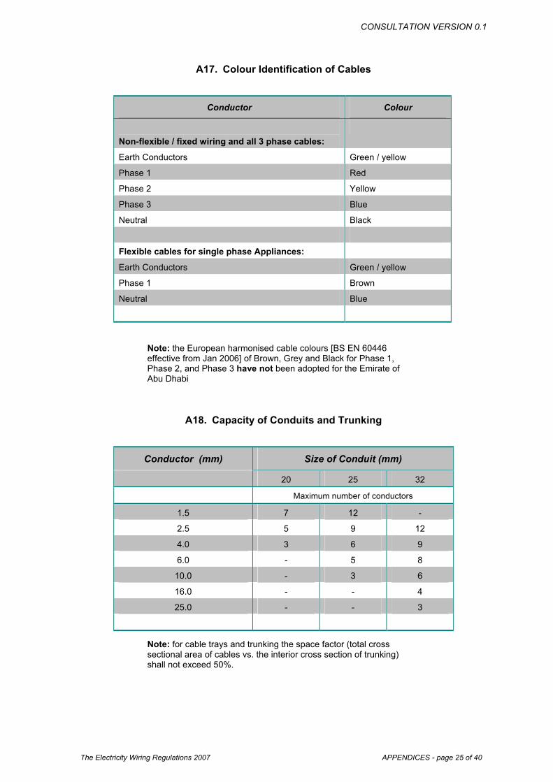
A17. Colour Identification of Cables
Note: the European harmonised cable colours [BS EN 60446 effective from Jan 2006] of Brown, Grey and Black for Phase 1, Phase 2, and Phase 3 have not been adopted for the Emirate of Abu Dhabi
A18. Capacity of Conduits and Trunking
Note: for cable trays and trunking the space factor (total cross sectional area of cables vs. the interior cross section of trunking) shall not exceed 50%.
Conductor Colour
Non-flexible / fixed wiring and all 3 phase cables:
Earth Conductors Green / yellow
Phase 1 Red
Phase 2 Yellow
Phase 3 Blue
Neutral Black
Flexible cables for single phase Appliances:
Earth Conductors Green / yellow
Phase 1 Brown
Neutral Blue
Conductor (mm) Size of Conduit (mm)
20 25 32
Maximum number of conductors
1.5 7 12 -
2.5 5 9 12
4.0 3 6 9
6.0 - 5 8
10.0 - 3 6
16.0 - - 4
25.0 - - 3

CONSULTATION VERSION 0.1
The Electricity Wiring Regulations 2007 APPENDICES - page 26 of 40
A19. IP Coding for Ingress Protection
The IP (Ingress Protection) system of coding provides a standardised interpretation of the level of physical protection that equipment or enclosures maybe designed for. The coding system is specified in BS EN 60529: 1992 (adopted from IEC 529: 1989). The first digit of the code specifies protection against ingress of foreign objects of varying size, ranging from hands / fingers to fine dust particles. The second digit specifies protection against ingress of moisture, ranging from free falling water, to immersion in water. BS EN 60529 does not specify protection against the risk of explosion, humidity and corrosive gases. If enclosures or equipment is drilled or knockouts removed, suitable measures should be taken to restore the equipment to the original IP rating.
Typical Examples: (a) Domestic 13A socket outlet: IP 53 (b) Outdoor extension lead & socket: IP 64 (c) Outdoor weather-proof light switch: IP 66
Ingress Protection - IP Codes
First Digit - Protection against ingress by solid
objects
Second Digit - Protection against ingress by
liquids
X Not tested or not applicable X Not tested or not applicable
0 No protection 0 No protection
1 Human hand or objects > 50mm 1 Vertically dripping water
2 Human finger or objects > 12mm 2 Sprays of water < 15o from vertical
3 Objects > 2.5mm (e.g. tools or wires)
3 Sprays of water < 60o from vertical
4 Objects > 1.0mm (e.g. small wires)
4 Splashes of water (from any direction)
5 Limited protection against dust (to the extent that does not harm the equipment)
5 Low pressure jets of water (from any direction)
6 Totally protected against dust 6 Strong jets of water (from any direction)
7 Temporary immersion
8 Total immersion

CONSULTATION VERSION 0.1
The Electricity Wiring Regulations 2007 APPENDICES - page 27 of 40
A20. Standard Wiring Diagram Symbols
Note: additional wiring symbols may be taken from BS EN 60617
Symbol Description
Main Distribution Board (MDB)
Sub Main Distribution Board (SMDB)
Distribution Board (DB)
Air Circuit Breaker (ACB)
Moulded Case Circuit Breaker (MCCB)
Miniature Circuit Breaker (MCB)
Earth Leakage Circuit Beaker (ELCB)
Fuse
Link
kWh meter (direct reading)
kWh meter (ct operated)
Switched line (e.g. connecting all outlets controlled by one switch)
Circuit line (e.g. connecting all outlets on the same circuit)
13A switched socket outlet
15A switched socket outlet
20A double pole switch with neon indicator
30A double pole switch
Shaver socket to BS 3052
Cooker control unit
M
M
CCU

CONSULTATION VERSION 0.1
The Electricity Wiring Regulations 2007 APPENDICES - page 28 of 40
WW
Appendix A20 continued … Note: additional wiring symbols may be taken from BS EN 60617
Symbol Description
Tungsten light fitting - ceiling mounted
Tungsten light fitting - wall mounted
Fluorescent light fitting - ceiling mounted
Fluorescent light fitting - wall mounted
Light switch - 1 way
Light switch - 2 way
Light switch - intermediate way
Light switch - pull cord operated
Light switch - key operated
Light switch - weather proof type
Exhaust fan
Ceiling mounted fan
Low level cooker outlet connection
Earth connection
CONSULTATION VERSION 0.1
The Electricity Wiring Regulations 2007 APPENDICES - page 29 of 40
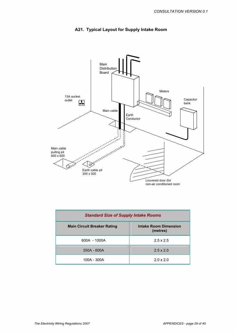
Main Distribution Board
Main cableEarth Conductor
Main cablepulling pit 600 x 600
Earth cable pit300 x 300
13A socket outlet
Meters
Capacitorbank
Louvered door (fornon-air conditioned room
A21. Typical Layout for Supply Intake Room
Standard Size of Supply Intake Rooms
Main Circuit Breaker Rating Intake Room Dimension (metres)
600A - 1000A 2.5 x 2.5
350A - 600A 2.5 x 2.0
100A - 300A 2.0 x 2.0

CONSULTATION VERSION 0.1
The Electricity Wiring Regulations 2007 APPENDICES - page 30 of 40
Fused spur tofixed appliance
Spur socket outlet
To Final DB
Spur socket outlets
Fused spur tofixed appliance
Spur socket outlet
To Final DB
Spur socket outlets
A22. Typical Layout for Ring Circuits
CONSULTATION VERSION 0.1
The Electricity Wiring Regulations 2007 APPENDICES - page 31 of 40
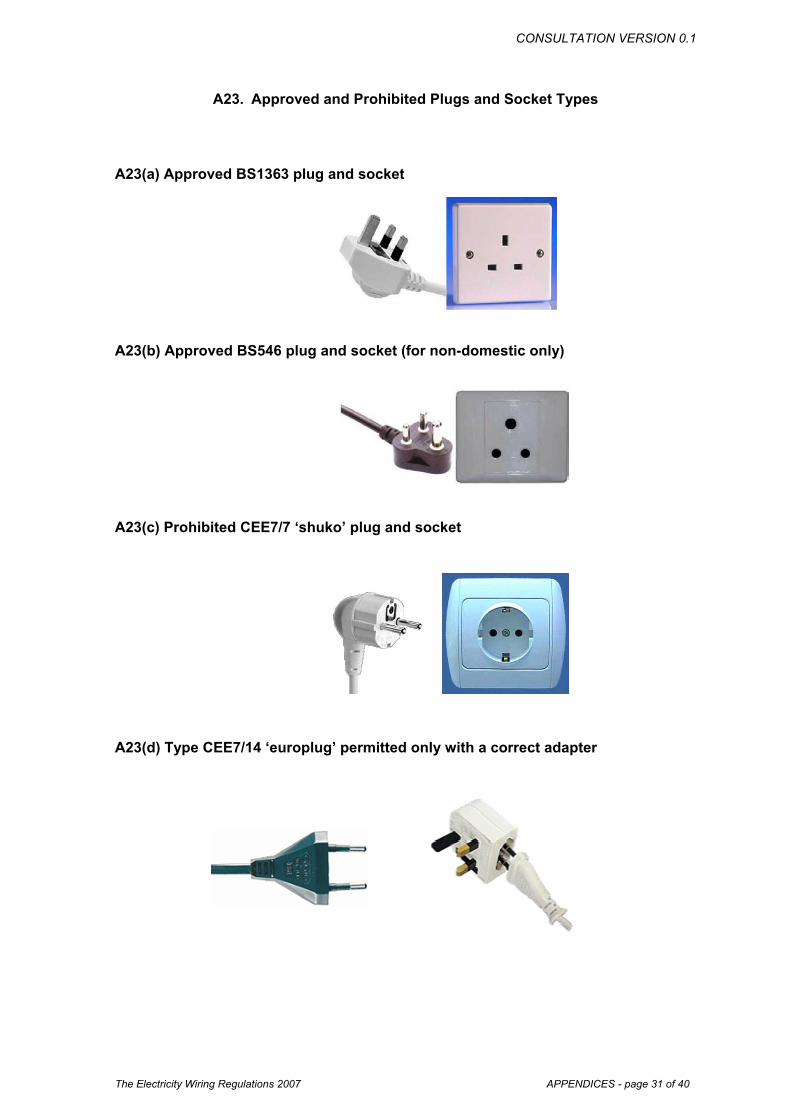
A23. Approved and Prohibited Plugs and Socket Types
A23(a) Approved BS1363 plug and socket
A23(b) Approved BS546 plug and socket (for non-domestic only)
A23(c) Prohibited CEE7/7 ‘shuko’ plug and socket A23(d) Type CEE7/14 ‘europlug’ permitted only with a correct adapter

CONSULTATION VERSION 0.1
The Electricity Wiring Regulations 2007 APPENDICES - page 32 of 40
A24. Minimum Recommended Number of Socket Outlets
Room Minimum number of outlets
Kitchen:
13A switched socket outlets
20A spur connection points (for washing machine, dryer etc)
45A cooker control unit
4
4
1
Bedrooms 4
Lounge / dining 4
Hall / corridor 1
Bathrooms Only BS3535 shaver socket

CONSULTATION VERSION 0.1
The Electricity Wiring Regulations 2007 APPENDICES - page 33 of 40
A25. Method for Measuring Earth Resistance
(i) a proprietary earth electrode test device should be used (ii) auxiliary earth spikes should be applied at least 5m apart and 5m distant from the
electrode under test (iii) a earth resistance value of less than 5 ohms is required for a Customer Earthed
System (iv) an additional number of electrodes may be required (or deeper electrodes) to
achieve the required earth resistance value (v) due consideration should be given to future changes in soil condition (e.g. drying
out) (vi) sufficient time should be allowed if special chemicals or salts are added to the
ground to improve the earth resistance values
A26. Method for Earth Loop Impedance Test
(i) Earth Fault Loop Impedance may be measured directly at the Supply Intake by specialist instruments
(ii) alternatively, if the external loop impedance is known, this may be added to the R1 + R2 test, to determine the total Earth Fault Loop Impedance
(iii) the main circuit breaker should be open and the test link at the Main Earth Terminal should be opened for these tests

CONSULTATION VERSION 0.1
The Electricity Wiring Regulations 2007 APPENDICES - page 34 of 40
A27. Method for Continuity Tests
(i) All Earth Conductors, phase conductors and neutral conductors should be checked
(ii) A low reading ohmmeter is required capable of reading down to 0.01 ohms, and producing a test current of 200mA, and having an open circuit voltage of 4 to 24 volts
(iii) Measurement of R1+R2 (phase conductor resistance + earth conductor resistance) can be made for each circuit by bridging phase and earth terminals at the relevant Distribution Board and measuring the resistance between phase and earth terminals at the most remote connection point or socket outlet
(iv) separate values of R1 and R2 can be made using a long test lead so that measurement is directly from one end of each conductor to the other (note: the resistance of the test leads should be subtracted from the result)
(v) testing of Earth Bonding Conductors should be made using the long lead method
A28. Method for Insulation Resistance Test
(i) Insulation resistance should be checked between all live conductors, and between live conductors and Earth
(ii) the test instrument should be capable of producing a d.c. test voltage of 500V when loaded to 1mA and be capable of measurement of up to 200Mohm
(iii) the minimum acceptable value of insulation resistance for any test is 0.5Mohm (iv) the supply should be disconnected and all current using equipment switched off
(including neon indicator lamps, and voltmeters mounted on Distribution Boards etc)
(v) insulation measurements should be taken from each Distribution Board between each pair of phases in turn, between each phase and neutral, and between each phase and Earth
(vi) a final test should be made between the neutral bar and earth; if a reading of less than 2Mohm is observed, then each neutral conductor should be tested separately to Earth.
A29. Method for Polarity Tests
(i) the polarity test is required to confirm that all single pole devices, and lamp holders with an outer neutral contact (i.e. ES screw type) are correctly connected
(ii) single pole devices must only be connected in the live conductor and the neutral conductor of all circuits must be continuous
(iii) the test method used is the same as for the continuity test (appendix A27).
CONSULTATION VERSION 0.1
The Electricity Wiring Regulations 2007 APPENDICES - page 35 of 40
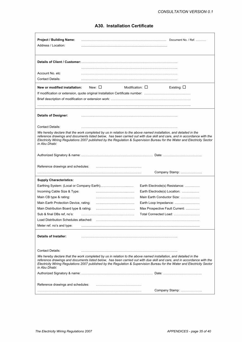
A30. Installation Certificate
Project / Building Name: .............................................................................................. Document No. / Ref. .............
Address / Location: ...............................................................................................
Details of Client / Customer: ……………………………………………………………………………..
……………………………………………………………………………..
Account No. etc ……………………………………………………………………………..
Contact Details: ……………………………………………………………………………..
New or modified installation: New: Modification: Existing:
If modification or extension, quote original Installation Certificate number: ……………………………….……
Brief description of modification or extension work: ………………………………………………………………..
…………………………………………………………………………………………………………………..………..
Details of Designer: ……………………………………………………………………………..
Contact Details: ……………………………………………………………………………..
We hereby declare that the work completed by us in relation to the above named installation, and detailed in the reference drawings and documents listed below, has been carried out with due skill and care, and in accordance with the Electricity Wiring Regulations 2007 published by the Regulation & Supervision Bureau for the Water and Electricity Sector in Abu Dhabi:
Authorized Signatory & name: ………………………………………………………… Date: ………………………….…..
Reference drawings and schedules: ……………………………………
…………………………………………………………………………………… Company Stamp: ………………..
Supply Characteristics:
Earthing System: (Local or Company Earth)..…………………......… Earth Electrode(s) Resistance: ……..……
Incoming Cable Size & Type: ………………………...…… Earth Electrode(s) Location: ……….……
Main CB type & rating: ………………………...…… Main Earth Conductor Size: ……...………
Main Earth Protection Device, rating: ……………………...……… Earth Loop Impedance: ……...…...………
Main Distribution Board type & rating: ……………………………… Max Prospective Fault Current: ….………
Sub & final DBs ref, no’s: ……………...............………..……….. Total Connected Load: ……………………
Load Distribution Schedules attached: ………………………………………………………….………………………..
Meter ref. no’s and type: ...................................................................................................................................
Details of Installer: ……………………………………………………………………………..
Contact Details: ……………………………………………………………………………..
We hereby declare that the work completed by us in relation to the above named installation, and detailed in the reference drawings and documents listed below, has been carried out with due skill and care, and in accordance with the Electricity Wiring Regulations 2007 published by the Regulation & Supervision Bureau for the Water and Electricity Sector in Abu Dhabi:
Authorized Signatory & name: ………………………………………………………… Date: ………………………….…..
Reference drawings and schedules: ……………………………………
…………………………………………………………………………………… Company Stamp: ………………..

CONSULTATION VERSION 0.1
The Electricity Wiring Regulations 2007 APPENDICES - page 36 of 40
A31. Inspection Report
Project / Building Name: .............................................................................................. Document No. / Ref. .............
Address / Location: ..........................................................................................................
Customer/owner: ……………………………………………………………………………..
Contact Details: ……………………………………………………………………………..
New or modified or existing installation: New: Modification: Existing:
Original Installation Certificate number: ……………………………….……
Brief description of modification or extension work: ………………………………………………………………..
…………………………………………………………………………………………………………………..………..
Inspected & tested by: ……………………………………………………………………………..
Contact Details: ……………………………………………………………………………..
We hereby declare that the inspection and testing completed by us in relation to the above named installation, and detailed in the reference documents listed below, has been carried out with due skill and care, and in accordance with the Electricity Wiring Regulations 2007 published by the Regulation & Supervision Bureau for the Water and Electricity Sector in Abu Dhabi:
Authorized Signatory & name: ………………………………………………………… Date: ………………………….…..
Reference drawings and schedules: ……………………………………
…………………………………………………………………………………… Company Stamp: ………………..
Supply Characteristics:
Earthing System: (Local or Company Earth)..…………………......… Earth Electrode(s) Resistance: ……..……
Incoming Cable Size & Type: ………………………...…… Earth Electrode(s) Location: ……….……
Main CB type & rating: ………………………...…… Main Earth Conductor Size: ……...………
Main Earth Protection Device, rating: ……………………...……… Earth Loop Impedance: ……...…...………
Main Distribution Board type & rating: ……………………………… Max Prospective Fault Current: ….………
Sub & final DBs ref, no’s: ……………...............………..……….. Total Connected Load: ……………………
Load Distribution Schedules attached: ………………………………………………………….………………………..
Meter ref. no’s and type: ...................................................................................................................................
General Details of Inspection & Testing
Date of last inspection & test: ...................................................................
Any modifications noted: ...................................................................
Have modifications been recorded: Yes / No details: ..................................
Age of installation & estimated age of modifications: ..................................
Date of next inspection: .............................................................................................
Any dangerous conditions or urgent work required (give details over leaf): Yes / No
Any work or improvements recommended (give details over leaf): Yes / No
Extent of inspection All: Part:
Areas not tested / inspected: ...................................................................................
Criteria of Inspections:
For each of the items listed over leaf the following visual checks have been completed:
(a) Protection against direct contact (insulation of live parts, adequate barriers and enclosures)
(b) Protection against indirect contact (presence of earthing conductors, equi-potential bonding conductors, presence of earth leakage devices ELCB or RCD)
(c) Correct positioning of apparatus for safe access and security (including proximity of other services such as alarm systems, water, telephone, gas etc)
(d) Correct signs, warnings and identification labels on all equipment and circuits
(e) Overall condition of apparatus (signs of aging or deterioration to be noted)
(f) Integrity of all connections, no signs of overheating or overloading
[quote non compliance with Regulations, para. no. where required]
CONSULTATION VERSION 0.1
The Electricity Wiring Regulations 2007 APPENDICES - page 37 of 40
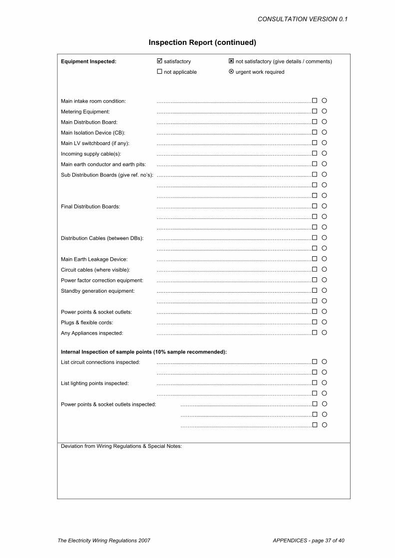
Inspection Report (continued)
Equipment Inspected: satisfactory not satisfactory (give details / comments)
not applicable urgent work required
Main intake room condition: ………...............................................................………………......… Metering Equipment: ………...............................................................………………......… Main Distribution Board: ………...............................................................………………......… Main Isolation Device (CB): ………...............................................................………………......… Main LV switchboard (if any): ………...............................................................………………......… Incoming supply cable(s): ………...............................................................………………......… Main earth conductor and earth pits: ………...............................................................………………......… Sub Distribution Boards (give ref. no’s): ………...............................................................………………......… ………...............................................................………………......… ………...............................................................………………......… Final Distribution Boards: ………...............................................................………………......… ………...............................................................………………......… ………...............................................................………………......… Distribution Cables (between DBs): ………...............................................................………………......… ………...............................................................………………......… Main Earth Leakage Device: ………...............................................................………………......… Circuit cables (where visible): ………...............................................................………………......… Power factor correction equipment: ………...............................................................………………......… Standby generation equipment: ………...............................................................………………......… ………...............................................................………………......… Power points & socket outlets: ………...............................................................………………......… Plugs & flexible cords: ………...............................................................………………......… Any Appliances inspected: ………...............................................................………………......…
Internal Inspection of sample points (10% sample recommended):
List circuit connections inspected: ………...............................................................………………......… ………...............................................................………………......… List lighting points inspected: ………...............................................................………………......… ………...............................................................………………......… Power points & socket outlets inspected: ………...............................................………………......… ………...............................................………………......… ………...............................................………………......… Deviation from Wiring Regulations & Special Notes:

CONSULTATION VERSION 0.1
The Electricity Wiring Regulations 2007 APPENDICES - page 38 of 40
A32. Testing Report
Project / Building Name: .......................................................................................................... Document No. / Ref. .................... Test Instruments (serial no.s)
Address / Location: .......................................................................................................... Tested by .................................. Loop impedance tester: ...................................
Distribution Board No. / Ref. .......................................................................................................... Date: ...................... Continuity tester: ..............................................
Fed from: .......................................................................................................... Date: ...................... Insulation tester: ..............................................
Continuity Test (ohms) Insulation Resistance (M-ohms)
Functional Test
CCT Identity
No.
CCT ref. No.
MCB rating
(A)
Wire size (cct.) mm2
Wire size
(ecc.) mm2
Circuit name
R1 + R2 R2 Ring L-L Live-Earth
Pol
arity
Earth loop
(Z) RCD
time (ms)
Other
Remarks
Deviation from Wiring Regulations & Special Notes:

CONSULTATION VERSION 0.1
The Electricity Wiring Regulations 2007 APPENDICES - page 39 of 40
A33. Load Distribution Schedule Project / Building Name: ..........................................................................................................
Address / Location: ..........................................................................................................
Distribution Board No. / Ref. ........................................ Incoming Cable size / type and ECC: .......................................................... Date: ......................
Fed from: ........................................ Main breaker type & rating: ...................................................................................... Document No. / Ref. ....................
Circuit Load in kW CCT Identity
No.
CCT ref. No.
MCB rating
(Amps)
Phase & Neutral
Size mm2
Earth Conductor size mm2
Circuit name / Point reference
No. of points
Watts per
point R Y B Remarks
R1
Y1
B1
R2
Y2
B2
R3
Y3
B3
TOTAL CONNECTED LOAD _ _ _ _ _ kW Remarks:
TOTAL LOAD AFTER DIVERSITY _ _ _ _ _ kW Remarks:
CONSULTATION VERSION 0.1
The Electricity Wiring Regulations 2007 APPENDICES - page 40 of 40