
Computerized Expert System for Lighting Grids
6
Computerized Expert System for Lighting Grids COSTIN CEPISCA Faculty of Electrical Engineering Politehnica University of Bucharest Splaiul Independentei 313, s.6, Bucharest ROMANIA [email protected] http://www.electro.pub.ro HORIA ANDREI Faculty of Electrical Engineering University Valahia of Targoviste ROMANIA [email protected] SORIN DAN GRIGORESCU Faculty of Electrical Engineering Politehnica University of Bucharest ROMANIA [email protected] MIRCEA PERPELEA University of Pitesti ROMANIA [email protected] LAURENTIU STANCU Amiras C&L Impex SRL Targoviste ROMANIA [email protected] VALENTIN DOGARU ULIERU Faculty of Electrical Engineering University Valahia of Targoviste ROMANIA [email protected] Abstract: - An important equipment of a lighting system is the switch on point, which ensures the correct supply of the lamps on an hour interval imposed by the beneficiary and thus also provides the energy economy. The paper proposes an expert system which uses the programmable automat ALPHA XL and which leads an automat system for switch on points in public lighting systems. It is presented the hardware and software implemented application and the performances analysis of the proposed system. Key-Words: - lighting system, switch point, expert system, programmable automat. 1 Introduction The present switches on points of lighting grids have no automated systems, starting to function and disconnecting, most often, at the manual action [1]-[5]. The new intelligent equipments presented in this paper, to increase the efficiency of the public lighting [6]-[9], include more functions: switch on/off depending on the local lighting state; the possibility of switch on/off Proceedings of the 7th WSEAS International Conference on CIRCUITS, SYSTEMS, ELECTRONICS, CONTROL and SIGNAL PROCESSING (CSECS'08) ISSN: 1790-5117 133 ISBN: 978-960-474-035-2
Transcript of Computerized Expert System for Lighting Grids
Computerized Expert System for Lighting Grids
COSTIN CEPISCA
Faculty of Electrical Engineering
Politehnica University of Bucharest
Splaiul Independentei 313, s.6, Bucharest
ROMANIA
[email protected] http://www.electro.pub.ro
HORIA ANDREI
Faculty of Electrical Engineering
University Valahia of Targoviste
ROMANIA
SORIN DAN GRIGORESCU
Faculty of Electrical Engineering
Politehnica University of Bucharest
ROMANIA
MIRCEA PERPELEA
University of Pitesti
ROMANIA
LAURENTIU STANCU
Amiras C&L Impex SRL Targoviste
ROMANIA
VALENTIN DOGARU ULIERU
Faculty of Electrical Engineering
University Valahia of Targoviste
ROMANIA
Abstract: - An important equipment of a lighting system is the switch on point, which ensures the correct supply of
the lamps on an hour interval imposed by the beneficiary and thus also provides the energy economy. The paper
proposes an expert system which uses the programmable automat ALPHA XL and which leads an automat system for
switch on points in public lighting systems. It is presented the hardware and software implemented application and
the performances analysis of the proposed system.
Key-Words: - lighting system, switch point, expert system, programmable automat.
1 Introduction The present switches on points of lighting grids have no
automated systems, starting to function and
disconnecting, most often, at the manual action [1]-[5].
The new intelligent equipments presented in this paper,
to increase the efficiency of the public lighting [6]-[9],
include more functions: switch on/off depending on the
local lighting state; the possibility of switch on/off
Proceedings of the 7th WSEAS International Conference on CIRCUITS, SYSTEMS, ELECTRONICS, CONTROL and SIGNAL PROCESSING (CSECS'08)
ISSN: 1790-5117 133 ISBN: 978-960-474-035-2
depending on the functioning preliminary schedule; the
knowledge from distance of the functioning state of the
respective electric network, the signaling at the
appearance of some possible defects; the possibility of
remote controlling the switch on/off commands; the
knowledge possibility from a central point of the
energetic consumptions in each switch on point and the
state of the respective network, especially that the
measured quantities are most often non-sinusoidal; the
possibility of establishing economic functioning regimes,
inclusive at voltages lower than nominal voltages; the
endowment with a distance transmitting device of the
command and measuring information: radio, wireless etc.
These new functions can be implemented using
hardware and software specialized elements, such as
programmable automats ALPHA XL. The programmable
automat (PLC) is a device which allows the control and
the automation of the working regimes of several
electrical equipments. The PLC receives signals through
the agency of its inputs, processes them after an
established program and transmits signals to its outputs.
The specialized program is realized with a
programming soft. Through the program, we can
command the inputs and outputs as we wish; we can
measure times and perform calculus operations. The
main characteristics of a PLC are: the maximum number
of inputs/outputs, the memory capacity and the calculus
speed. The compact programmable automats are defined
through the next system characteristics:
• programming with the same software package,
regardless of the number of inputs/outputs;
• possibilities of local and distant extension;
• integrated interface for communication;
• removable terminal blocks, with screws;
• compact gauge.
Through the agency of the menu and only with the help
of the buttons on the apparatus, the command scheme
can be introduced directly as a scheme of connections
with contacts and relay coils. The introduction can be
alternatively made using ALPHA XL and a PC. On the
MFD screen or on the PC, the active states from the
command scheme can be immediately observed and thus
precious time is saved.
2 Using the PLC to control the lighting
systems Regarding the use of this programmable automat for the
lighting control, we can make the following
appreciations:
- the lighting switch on/off are possible in the
centralized or decentralized variant;
- the lighting switch on and switch off are possible in the
centralized or decentralized variant through the impulse
relay function;
- the lighting switch off command can be realized through
the agency of the clock delay, which facilitates the
centralized disconnection of the lighting and the energy
economy;
- a base device can control up to 12 independent lighting
groups. Special commands for lighting can be realized,
such as centralized lighting for maintenance activities and
automatic commutation for reduced lighting;
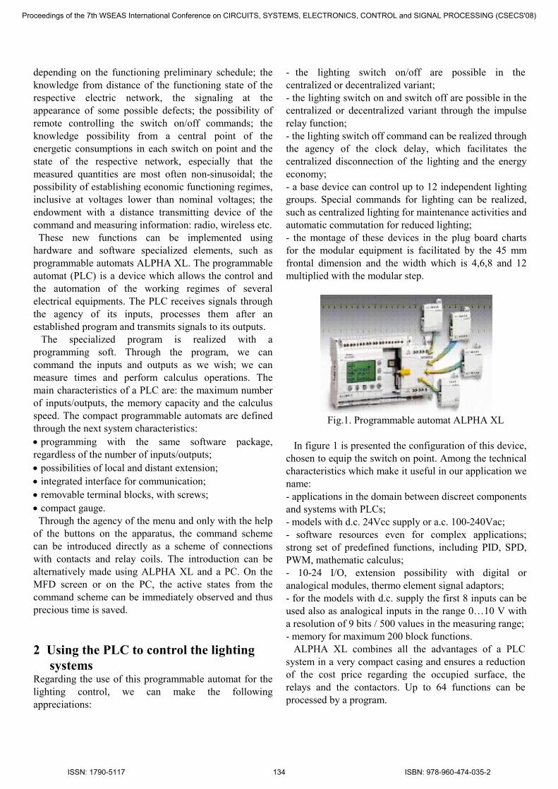
- the montage of these devices in the plug board charts
for the modular equipment is facilitated by the 45 mm
frontal dimension and the width which is 4,6,8 and 12
multiplied with the modular step.
Fig.1. Programmable automat ALPHA XL
In figure 1 is presented the configuration of this device,
chosen to equip the switch on point. Among the technical
characteristics which make it useful in our application we
name:
- applications in the domain between discreet components
and systems with PLCs;
- models with d.c. 24Vcc supply or a.c. 100-240Vac;
- software resources even for complex applications;
strong set of predefined functions, including PID, SPD,
PWM, mathematic calculus;
- 10-24 I/O, extension possibility with digital or
analogical modules, thermo element signal adaptors;
- for the models with d.c. supply the first 8 inputs can be
used also as analogical inputs in the range 0…10 V with
a resolution of 9 bits / 500 values in the measuring range;
- memory for maximum 200 block functions.
ALPHA XL combines all the advantages of a PLC
system in a very compact casing and ensures a reduction
of the cost price regarding the occupied surface, the
relays and the contactors. Up to 64 functions can be
processed by a program.
Proceedings of the 7th WSEAS International Conference on CIRCUITS, SYSTEMS, ELECTRONICS, CONTROL and SIGNAL PROCESSING (CSECS'08)
ISSN: 1790-5117 134 ISBN: 978-960-474-035-2

Each of the valid functions (time, numerator, analog
processing converter, calendar/clock, etc.) can be used in
all of the programs, every time when needed. ALPHA
XL includes a tripling of the program capacity up to 200
functions and a big screen, extension options and a
second communication block, 15 new functions suited to
the instruction set, including mathematical operations,
PWM and SMS messages functions. The easy operating
and the legible screen are two big advantages of ALPHA
XL, offering in the same time graphics from the moving
bar and text on screen. The three levels of password
protection prevent unauthorized access to the processed
parameters and data, which can be changed directly
through 8 key functions.
ALPHA XL is equipped with a communication
interface and with the possibility of ensuring an
automatic control through a GSM modem. Additionally,
it’s possible to send SMS texts to a mobile phone, e-mail
to a PC or fax. The extended analogical modules increase
the applications level. With these modules it’s possible to
generate voltage or current signals and to measure
temperature. The I/O points of the slave devices are
electronically recorded through the bus connection or the
PLC program introducing the master into the network.
All the controllers from the ALPHA series can be
programmed with the soft MS Windows AL PCS/WIN.
This software is very easy to use and doesn’t need the
user to have experience. The programming of ALPHA is
easy and is made placing the different elements of the
program into a graphic programming environment.
3 Hardware and software configuration
of PLC for controlling the switch on
point of public lighting systems To configure the programmable automat ALPHA XL for
the application related to the control of switch on points
in public lighting, [10], we take into account the next
requirements:
- Connecting the automat consumer, depending on the
lighting state, through the agency of a solar radiation
transducer or through manual command;
- Connecting the lighting network using an hour program,
depending on the day from the week;
- Supplying the network through the agency of voltage/
frequency converter;
- Supplying the lighting through the agency of an
autotransformer, in order decrease the lighting intensity
between certain hours (the reduction of the luminous
flux);
- Disconnecting the lighting in situations commanded by
the Civil Protection and the predefined command of an
alarming siren (with a certain sound clock);
- Disconnecting the lighting in function of the arisen
failures (over and sub voltage, over and sub current), to
identify the abnormal working of the installation (bus
interruptions, energy thieveries);
- Protection sensitizing depending on the chosen supply
variants: directly, converter, autotransformer;
- Metering the consumed energy (meter of impulses taken
from an administration system);
- Supervising the temperature and sending this value at the
control point (with the help of a temperature transducer).
Fig.2. Programming scheme.
3.1 Inputs and outputs assignations
The assignation of the inputs and the outputs are presented
below.
� Inputs:
I01 – Automation supply switch (network operating) –
digital, I02 - Luminous intensity transducer (0-10 V)-
analogical, I03- Automatic functioning switch depending
on digital light sensor, I04 – Automation functioning
switch depending on programming clock – digital, I05 –
Civil Alarm signal input – digital, I06 - Current
transducer signal input – (0-10V) analogical, I07-Voltage
transducer signal input (0-10V) analogical, I08-
Temperature transducer signal input (0-10V)-analogical,
Proceedings of the 7th WSEAS International Conference on CIRCUITS, SYSTEMS, ELECTRONICS, CONTROL and SIGNAL PROCESSING (CSECS'08)
ISSN: 1790-5117 135 ISBN: 978-960-474-035-2

I09- Energy meter signal input (0-10V) - digital, I10-
Automation functioning switch with frequency
converter– digital, I11-Automation– digital.
� Outputs:
O01- Temperature (0-10V) –analogical, O02- Lighting
command – digital, O04 – Civil defense siren – digital,
O05 – Autotransformer servomotor – digital, O06-
Converter command ( 0-10 V) – analogical, O07– Output
for impulses proportional with consumed energy –
digital, O08 – Cabin fan command – digital.
The programming scheme and the utilization interface
are presented in figure 2, respectively in figure 3.
Fig.3. Utilization interface.
3.2 Program work algorithm
The input functions I01, I02, and I03 give the general
validation conditions for the lighting command O 02.[11]
The input analogical signal, received from the
twilight transducer is compared with the values imposed
in the lighting controller B 15 and B 16. Depending on
this comparison the automat will decide if it’s the
moment to command the connection of the public
lighting.
The system state is visualized on the display screen B 17
and B 20 (B 17 indicates the “lighting turned on” state
and B 20 indicates the “lighting turned off” state). The
two displays are conditioned by the Boolean function B
18, like in figure 4.
Fig. 4. The system state.
The “Disconnect” function is activated through the
application of a digital system at the I05 input. In this
state, the automat commands the public lighting
disconnection (if the conditions were fulfilled). The digital
signal enters in the loop B 25, conditioning depending on
the command key), B 26 (signal negation), generating a
signal in B 28 (“and” logic), disconnecting the lighting
contactor. The display is presented in figure 5.
Fig. 5. The display is activated.
The supervising of the failures (voltage and current) is
made with the functional blocks B32 and B33 which take
over the analogical information from the inputs I06 and
I07 through the agency of B31 and B32. These states are
shown in figure 6, respectively in figure 7.
Fig. 6. The functional blocks B32 and B33.
Proceedings of the 7th WSEAS International Conference on CIRCUITS, SYSTEMS, ELECTRONICS, CONTROL and SIGNAL PROCESSING (CSECS'08)
ISSN: 1790-5117 136 ISBN: 978-960-474-035-2

Fig. 7. The functional blocks B31.
The visualization of the voltage and current protection
state is made through the optic blocks B 31 and B 32, is
show in figure 8.
Fig. 8. The integrated signal of voltage and current.
Depending on the chosen automation variant: through the
autotransformer or through the converter, the current and
voltage protections automatically modify their working
parameters.
The failure, figure 9, is shown on the B 23 display. When
the converter works, the input signals integrate in blocks
B06 and B07, through the agency of the amplifiers B04
and B05. The resulted signal integrates in blocks B 08
and B 09. The failure is shown on the B 22 display. The
failure signals are totalized through the “OR” logic in the
functional block B10 - figure 10. When the
autotransformer works, the input signals integrate in the
B12 and B13 blocks, through the agency of the
amplifiers B64 and B11. The resulted signal integrates in
blocks B19 and B21.
The automation working in the autotransformer variant is
realized when at the I11 input a digital signal is applied,
signal which is also found at the terminals of B 02.
The autotransformer is operated by the digital output O
05, commanded by the B 02 “AND” block. The working
takes place when all the three signals are simultaneously
applied from I 11, I 01 and the programming clock B 03.
With the help of this clock we can program the period in
which the luminous intensity will reduce (between what
hours and what days), shown in figure 11.
Fig. 9. The failure.
Fig. 10. The functional blocks B10.
Fig. 11 The set of time switch.
The automation functioning with the help of the
frequency converter is realized when at the I 10 input
a digital signal is applied and when the system is in
operating state (I01 is supplied). The signal from I10
is applied to the integrator blocks B52 and B55
which also take over the analogical information from
Proceedings of the 7th WSEAS International Conference on CIRCUITS, SYSTEMS, ELECTRONICS, CONTROL and SIGNAL PROCESSING (CSECS'08)
ISSN: 1790-5117 137 ISBN: 978-960-474-035-2
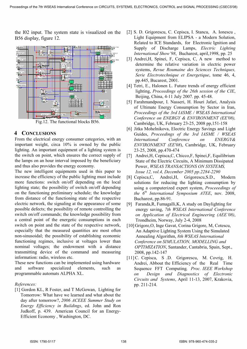
the I02 input. The system state is visualized on the
B56 display, figure 12.
Fig.12. The functional blocks B56.
4 CONCLUSIONS From the electrical energy consumer categories, with an
important weight, circa 10% is owned by the public
lighting. An important equipment of a lighting system is
the switch on point, which ensures the correct supply of
the lamps on an hour interval imposed by the beneficiary
and thus also provides the energy economy.
The new intelligent equipments used in this paper to
increase the efficiency of the public lighting must include
more functions: switch on/off depending on the local
lighting state; the possibility of switch on/off depending
on the functioning preliminary schedule; the knowledge
from distance of the functioning state of the respective
electric network, the signaling at the appearance of some
possible defects; the possibility of remote controlling the
switch on/off commands; the knowledge possibility from
a central point of the energetic consumptions in each
switch on point and the state of the respective network,
especially that the measured quantities are most often
non-sinusoidal; the possibility of establishing economic
functioning regimes, inclusive at voltages lower than
nominal voltages; the endowment with a distance
transmitting device of the command and measuring
information: radio, wireless etc.
These new functions can be implemented using hardware
and software specialized elements, such as
programmable automats ALPHA XL.
References:
[1] Gordon KL, R Foster, and T McGowan, Lighting for
Tomorrow: What have we learned and what about the
day after tomorrow?, 2006 ACEEE Summer Study on
Energy Efficiency in Buildings, ed. John and Ron
Judkoff, p. 439. American Council for an Energy-
Efficient Economy , Washington, DC.
[2] S. D. Grigorescu, C. Cepisca, I. Stancu, A. Ionescu ,
Light Equipment from ELIPSA - a Modern Solution,
Related to ICE Standards, for Electronic Ignition and
Supply of Discharge Lamps, Electric Lighting
International Show’98, Bucharest, april,1998, pp. 25
[3] Andrei,H, Spinei, F, Cepisca, C, A new method to
determine the relative variation in electric power
systems, Revue Roumaine des Sciences Techniques,
Serie Electrotechnique et Energetique, tome 46, 4,
pp.445, Bucarest, 2001.
[4] Tetri, E., Halonen L. Future trends of energy efficient
lighting, Proceedings of the 26th session of the CIE,
Beijing, China, 4-11 July 2007. pp. 45-48.
[5] Farahmandpour, I. Nasseri, H. Houri Jafari, Analysis
of Ultimate Energy Consumption by Sector in Iran,
Proceedings of the 3rd IASME / WSEAS International
Conference on ENERGY & ENVIRONMENT (EE'08),
Cambridge, UK, February 23-25, 2008 pp,151-158
[6] Jitka Mohelnikova, Electric Energy Savings and Light
Guides, Proceedings of the 3rd IASME / WSEAS
International Conference on ENERGY&
ENVIRONMENT (EE'08), Cambridge, UK, February
23-25, 2008, pp.470-474
[7] Andrei,H, Cepisca,C, Chicco,F, Spinei,F, Equilibrium
State of the Electric Circuits, A Minimum Dissipated
Power , WSEAS TRANSACTIONS ON SYSTEMS,
Issue 12, vol.4, December 2005 pp.2284-2290
[8] Cepisca,C, Andrei,H, Grigorescu,S.D., Modern
solutions for reducing the lighting consumption by
using a computerized expert system, Proceeedings of
the 6th International Symposium ATEE, nov. 2008,
Bucharest, pp.86-91.
[9] Faranda,R, Fumagalli,K, A study on Daylighting for
energy saving, 7th WSEAS International Conference
on Application of Electrical Engineering (AEE’08),
Trondheim, Norway, July 2-4, 2008
[10] Grigore,O, Inge Gavat, Corina Grigore, M, Cotescu,
An Adaptive Lighting System Using the Simulated
Annealing Algorithm, 8th WSEAS International
Conference on SIMULATION, MODELLING and
OPTIMIZATION, Santander, Cantabria, Spain, Sept.,
2008, pp.142-147
[11] C. Cepisca, S .D. Grigorescu, M. Covrig, H.
Andrei, Abbout the Efficiency of the Real Time
Sequence FFT Computing, Proc. IEEE Workshop
on Design and Diagnostics of Electronic
Circuits and Systems, April 11-13, 2007, Krakovia,
pp. 211-214.
Proceedings of the 7th WSEAS International Conference on CIRCUITS, SYSTEMS, ELECTRONICS, CONTROL and SIGNAL PROCESSING (CSECS'08)
ISSN: 1790-5117 138 ISBN: 978-960-474-035-2