computer networks
35
OPTICAL FIBER COMMUNICATION 06EC72 CHAPTER 8 OPTICAL AMPLIFIERS AND OPTICAL NETWORK By VIJAYA KUMAR H R Asst. Professor,
-
Upload
sharth-kumar -
Category
Documents
-
view
13 -
download
0
description
computer networks very important
Transcript of computer networks

OPTICAL FIBER COMMUNICATION06EC72
CHAPTER 8
OPTICAL AMPLIFIERS AND OPTICAL NETWORK
By
VIJAYA KUMAR H R Asst. Professor,
Dept. of E&C AIET, Moodabidri, Mangalore

Outline of the talk
•Optical amplifier
•Basic applications and types
•SOA
•EDFA
•Optical network
•SONET/SDH
•Optical interfaces
•SONET/SDH rings
•High speed light waveguides

optical amplifier
An optical amplifier is a device which amplifies the optical signal directly without ever changing it to electricity. The light itself is amplified.
Reasons to use the optical amplifiers: Conventional amplifiers such as Repeater are more complex
and power. The operation here is fully electrically.
Variety of optical amplifier types exists, including:Semiconductor Optical Amplifiers (SOAs)Raman amplifiersErbium Doped Fibre Amplifiers (EDFAs) (most common).

General applications
In line amplifiers:In single mode link fiber dispersion is less only concentrate on spacing and small or simple amplification of the optical signal is sufficient to increase transmission distance.
Preamplifiers:Optical amplifier are used as front end preamplifier for an optical receiver. A weak optical signal is amplified before photo detection so that signal to noise ratio degradation caused by thermal noise in the receiver electronics can be suppressed.
Power amplifiers:These are device immediately after optical transmitter to boost the transmitted power. These helps to increase transmission distance .Can also used before splitter configuration in a Local area network.

General optical amplifiers:•All types of optical amplifiers increase the power level of incident light through a stimulated emission or an optical power transfer process.
•Structure of optical amplifier is similar to laser but without feedback. That is it just boos the optical signal levels but it cannot generate coherent optical output itself.
•Pump source – device absorb the energy supplied from external source. Pump supplies the energy to electrons in a an active medium which raises them to higher energy levels to produce a population inversion.
•In stimulated emission is the process by which an atomic electron (or an excited molecular state) interacting with an electromagnetic wave of a certain frequency may drop to a lower energy level, transferring its energy to that field. A photon created in this manner has the same phase, frequency, polarization, and direction of travel as the photons of the incident wave
•An incoming signal photon will trigger these excited electrons to drop to lower levels through a stimulated emission process. Since one incoming trigger photon stimulates many excited electrons to emit photons of equal energy as they drop to ground state, the result is an amplified optical signal.


Semiconductor optical amplifier
•SOA is essentially is essentially an InGaAsp laser that is operating below its threshold point.•Similar laser construction but no feedback.•Belong to a travelling wave amplifier category.•Optical signal travels through the device only once.•Signal gains energy in cavity.
Characteristics:• Polarization dependent – require polarization maintaining fiber • Relatively high gain ~20 dB • Output saturation power 5-10 dBm • Large BW. • Can operate at 800, 1300, and 1500 nm wavelength regions. • Compact and easily integrated with other devices • Can be integrated into arrays • High noise figure and cross-talk levels due to nonlinear phenomenon such as 4-wave mixing.

Erbium doped fiber amplifiers:
•The active medium in an optical fiber amplifier consists of a nominally 10 to 30 m length of optical fiber that has been lightly doped with rare earth element such as erbium( Er), ytterbium (Yb), Thulium (Tm), Praseodymium (Pr).
•The host fiber material can be standard silica, a fluoride based glass, or a tellurite glass.
•The operating regions of these devices depend on the host material and doping elements.
•A popular material for long haul telecommunication applications is a silica fiber doped with erbium, which is known as Erbium doped fiber amplifier or EDFA.
•Sometimes Yb is added to increase the pumping efficiency and amplifier gain.
•1530 TO 1560 nm region – Conventional band
•Various technique is used to extend to operate in different region.

•SOA use external current injection to excite electrons to higher energy levels, optical fiber amplifiers a use optical pumping.
•Photon to directly raise electron is into excited states.
•Optical pumping process requires the use of three energy levels, the top energy level to which electrons is elevated must lie energetically above desired lasing level.
•After reaching its excited state, the electron must release some of its energy and drop to the desired lasing level.
•From this level, a signal photon can then trigger the excited electron into stimulated emission, new photon created with appropriate energy.
•Er 3+ ions – erbium atom in silica with 3 outer electrons have higher energy level.
•Two principle levels for telecommunication applications are a meta stable level and pump level.
•Meta stable means that life times for transitions from this state to ground state are very long compared with lifetimes of states that led to this level. Pump level to transitions from ground state to top energy level.

•The pump band in top left of exists at a 1.27 ev separation from the bottom of the ground state. The wavelength is 980nm.
•The top of the meta stable band is separated from the bottom of ground state band by 0.841ev,•The wavelength is 1480nm.
•The bottom of meta stable band level c is separated from bottom of ground state band by 0.814ev. The wavelength is 1530 nm.
•The bottom of meta stable band is separated from top of the ground state band by 0.775ev. This energy is corresponds to 1600nm.
•So the possible pump wavelengths are 980 and 1480 nm.
•The photons emitted during transition of electrons b/w possible energy levels in metastable and ground state band range from 1530 nm to 1600nm.
•In normal operation at 980nm excited energy appears. This excited ions decay very quickly from pump band to metastable band within a microseconds.
•During the decay excess energy is released as phonons , mechanical vibrations in fiber.
•Within the metastable it moves to ground state.

•Another possible pump is use 1480 nm. The energy of these pump photons is very similar to signal photon energy but slightly higher. The absorption of 1480 nm pump photon excites an electron from ground state directly to lightly populated top of metastable level.
•In metastable level some of ions sitting.
•This decay phenomenon is spontaneous emission and adds to amplifier noise.
•Two more transitions occur when a flux of signal photons that have energies corrsponding to band gap energy b.w the ground state and metastable level passes throught the device.
•1. small portion of the external photons will be absorbed by ions in ground state which raise these ions to metastable level.•2. stimulated emission.

EDFA Architecture:
•Doped fiber.•One or more pump laser.•Passive wavelength coupler•Optical isolator•Tap coupler
•Three possible configurations of EDFA (Refer figure from text book KEISER)
•Co directional pumping•Counter directional pumping•Dual pumping

OPTICAL NETWORKS
• The optical network is data network built on fiber-optics technology, which sends data digitally, as light, through connected fiber strands.


Network terminology:
•Station: A collection of devices that network subscribers use to communicate are called stations.
•Networks: To establish connection between these stations, transmission paths run b/w them to form a collection of interconnected stations called network.
•Trunk: The term trunk normally refers to transmission line that runs b/w nodes or networks and supports large traffic loads.
•Topology: The topology is the logical manner in which nodes are link together by information transmitting channels to form a network
•Switching and routing: The transfer of information from source to destination through a series of intermediate nodes is switching and selection of suitable path through a network is routing.

Network categories:
•LAN - <1km.•MAN - < 50km.•WAN- > 50km.•Access network <= 20 km.
Enterprise and public network•Own network is enterprise network.•Only to members of organization.
•For general public use said to be Public network.•CO, Backbone, Long Haul Network, Passive Optical Network.

Open Systems Interconnection (OSI) model

Optical layer
•The introduction of second-generation optical networks adds yet another layer to the protocol hierarchy – the so-called optical layer. The optical layer is a server layer that provides services to other client layers. This optical layer provides light paths to a variety of client layers,
•The optical layer is a wavelength based concept and lies just above the physical layer.
•This mean physical layer provides a physical connection b/w two nodes, the optical layer provides light path services over that link.
•Light path is end to end connection that may pass through one or more intermediate nodes.
•The optical layer may carry out processes such as wavelength multiplexing, adding and dropping and wavelengths and support of optical cross connects or wavelength routed networks.

Optical fiber network topologies:

SONET/SDH:
•Evolution of Digital formats
•Whenever the bandwidth of a medium linking two devices is greater than the bandwidth needs of the devices, then the link can be shared.
•Multiplexing is the set of techniques that allows the simultaneous transmission of multiple signals across a single data link.
•Synchronous Optical Networking (SONET) and Synchronous Digital Hierarchy (SDH) are standardized protocols that transfer multiple digital bit streams over optical fiber using lasers or highly coherent light from light-emitting diodes (LEDs).
•In brief, SONET defines optical carrier (OC) levels and electrically equivalent synchronous transport signals (STSs) for the fiber-optic based transmission hierarchy.
• SONET in the United States and Canada, and SDH in the rest of the world.
•SONET defines optical signals and a synchronous frame structure for multiplexed digital traffic. It is a set of standards that define the rates and formats for optical networks specified in ANSI T1.105, ANSI T1.106, and ANSI T1.117.

90 columns
9 ro
ws
framing
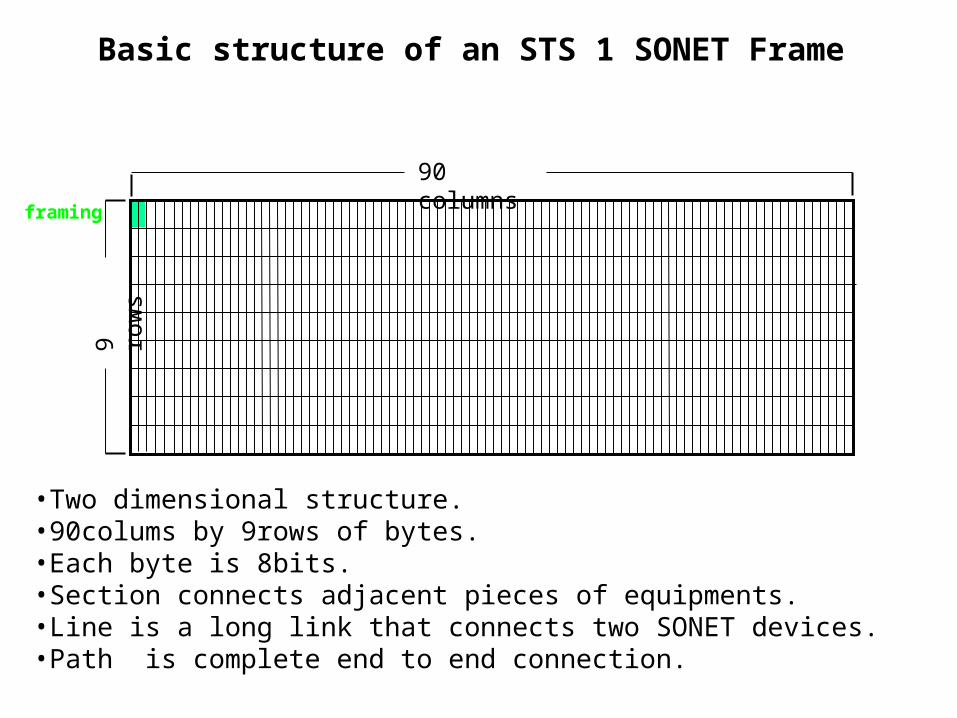
Basic structure of an STS 1 SONET Frame
•Two dimensional structure.•90colums by 9rows of bytes.•Each byte is 8bits.•Section connects adjacent pieces of equipments.•Line is a long link that connects two SONET devices.•Path is complete end to end connection.

Y(J)S SONET Slide 23
STS-1 OverheadThe STS-1 overhead consists of• 3 rows of section overhead
– frame sync (A1, A2)– section trace (J0)– error control (B1)– section orderwire (E1)– Embedded Operations Channel (Di)
• 6 rows of line overhead– pointer and pointer action (Hi)– error control (B2)– Automatic Protection Switching signaling (Ki)– Data Channel (Di)– Synchronization Status Message (S1)– Far End Block Error (M0)– line orderwire (E2)
A1 A2 J0
B1 E1 F1
D1 D2 D3
H1 H2 H3
B2 K1 K2
D4 D5 D6
D7 D8 D9
D10 D11 D12
S1 M0 E2
sectionoverhead
lineoverhead

•The fundamental SONET Frame has a 125micro seconds duration.
•Thus transmission bit rate of basic SONET signal is
STS1 = (90 bytes/row)(9rows/frame)(8bits/byte)/(125microseconds/frame) = 51.84Mb/s.
•STS 1 = Synchronous transport signal.
•All other SONET signals are integer multiples of this rate, so that an STS-N signal has a bit rate equal to N times 51.84 Mb/s.
•When an STS N signal is used to modulate an optical source, the logical STS N signal is first scrambled to avoid long strings of ones and zeros and to allow easier clock recover at the receiver.
•After undergoing electrical to optical conversion, the resultant physical layer optical signal is called OC-N where OC stands for OPTICAL CARRIER.
•N is range b/w 1 and 768, however in range from 1 to 192 values N = 1,3,12, 24, 192.

•In SDH the basic rate is equivalent to STS 3 OR 155.52 Mbps. This is called synchronous transport module level 1 (STM 1).
•Higher value STM M Or (STM N)
SONET SDH columns rate
STS-1 90 51.84M
STS-3 STM-1 270 155.52M
STS-12 STM-4 1080 622.080M
STS-48 STM-16 4320 2488.32M
STS-192 STM-64 17280 9953.28M

STS N SONET FRAME AND STM N SDH FRAME:
•1st three columns refers transport over head bytes that carry network management information.
•Remaining field of 87 columns is synchronous payload envelope(SPE) and carries user data plus nine bytes of path overhead (POH).
•The POH supports performance monitoring by the end equipment, status, signal labeling, a tracing function and a user channel.
•The 9 path over head bytes are always in a column and can be located any where in SPE.
•An important point to note is that synchronous byte interleaved multiplexing in SONET/SDH facilitates add/drop multiplexing of individual information channels in optical networks.
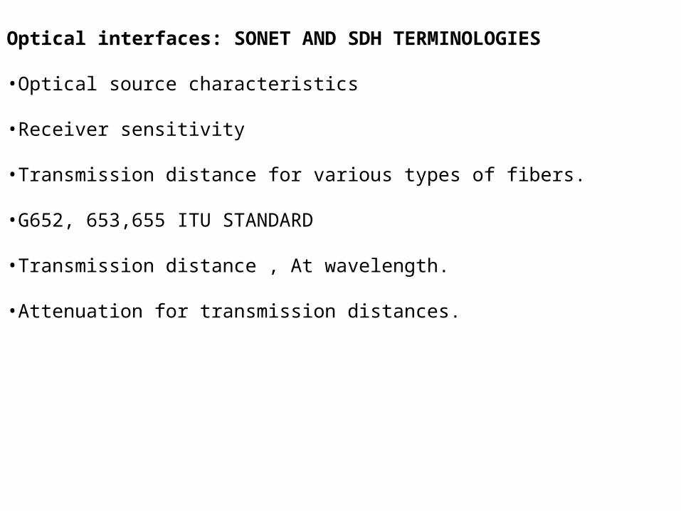
Optical interfaces: SONET AND SDH TERMINOLOGIES
•Optical source characteristics
•Receiver sensitivity
•Transmission distance for various types of fibers.
•G652, 653,655 ITU STANDARD
•Transmission distance , At wavelength.
•Attenuation for transmission distances.

SONET/SDH Rings:
•Can configured as either a ring or mesh architecture.
•This is done to crate loop diversity.
•The SONET/SDH rings are commonly called self healing rings since the traffic flowing along a certain path can automatically be switched to an alternate or standby path following failure or degradation of the link segment.
•Three main features with two alternative property 8 SONET/SDH types
1. There can be either 2 to 4 fibers running b/w the nodes on a ring.2. Operating signals can travel either clockwise only or in both directions around
the ring.3. Protection switching can be performed either via line switching or a path
switching scheme. A line switching moves all signal channels of entire OC N channel to protection fiber and Path switching moves individual payload channels within an OC N.

Two architecture have become popular (refer Figures from Kaiser 472 page no.)
1 two fiber, unidirectional, path switched ring (two fiber UPSR).2 two fiber or four fiber, bidirectional, line switched ring (two fiber or four fiber BLSR).

SONET/SDH networks:
•Variety of architectures.
•Point to links, linear chain, UPSR, BLSR, Rings
•OC 192 - BLSR, OC48 – BLSR,.
•ADM is fundamental network element uses in SONET/SDH.
•ADM is fully synchronous, byte oriented multiplexer that is used to add and drop sub channels with OC N signal.
•SONET/ SDH can also be implemented with multiple wavelengths = oc tx, wavelength 1, 2, .., Variable attenuator, Wavelength multiplexer, amplifier, Demultiplexers, OC rx.

•The small form-factor pluggable (SFP) is a compact, hot-pluggable transceiver used for both telecommunication and data communications applications.
•SFP transceivers are designed to support SONET, Gigabit Ethernet, Fibre Channel, and other communications standards. Due to its smaller size, SFP obsoletes the formerly ubiquitous gigabit interface converter (GBIC); the SFP is sometimes referred to as a Mini-GBIC although no device with this name has ever been defined in the MSAs.
•Different SFP available in market depends on requirements based on bandwidth, maximum distance.

Links operating at 40 Gbps
New challenges in terms of transceiver response characteristics, dispersion, polarization mode.
High capacity link.
On off key modulation format at this speed
Differential phase shift keying is alternate method.
BER
OTDM LINK operating at 160 Gbps: Refer figure from Keiser text book
Test 40 G bps in 160 Gbps
Bit interleaved multiplexing scheme
Channels at different rate but main speed is 160 Gbps.
Operation simply that laser produce stream of narrow RZ optical pulses at specified rate.
Then optical splitter divides the pulse train into N separate modulated independently.
If pulse stream is 10 G bps and N = 4 Then aggregate bit rate of N * B
Post, pre amplifiers are used.
At receiver side demultiplexed into original N independent data channels .

Optical add./drop multiplexing: Refer figure from Keiser text book
•OADM is a device which allows the insertion or extraction of one or more wavelengths from a fiber at a network node.
•Ex: OADM might have the capability to drop and insert three wavelengths from a set of N being transported over a single fiber. The remaining N-3 wavelengths pass unaffected through the OADM to the next node.
•At NODE COST greatly increases.
•Advantage is no signal processing is required for the set of wavelengths that passes straight through the OADM.
•Static in fixed add/drop configuration or dynamically reconfigured from a remote network management side.
•Fixed = OADM, Dynamic = ROADM.
•Fixed is not flexible.

Wavelength blocker configuration: Refer figure from Keiser text book
•Broad cast and select approach ROADM configuration.
•One branch is an express path and other branch is diverted to a drop site.
•Located in the express path is a device called wavelength blocker that can be configured to block those wavelengths that are to be received at the node.
Wavelength selective switch:
•WSS directs each wavelength entering a common input port to any one of multiple number of out put ports.
Optical switching:
•More nodes, more application
•More speed
•HDTV, VOIP, HSI etc,,. Need optical switching
•OED operation is depends on data rate and protocol