Introduction to Physical Layer Computer Networks Computer Networks Term B14.
38
Introduction to Physical Layer Computer Networks Term B14
-
Upload
geraldine-holt -
Category
Documents
-
view
236 -
download
1
Transcript of Introduction to Physical Layer Computer Networks Computer Networks Term B14.
Introductionto
Physical Layer
Introductionto
Physical Layer
Computer Networks Term B14
Physical Layer OutlinePhysical Layer Outline
Definitions Multiplexing Transmission Media End System Choices Residential Configurations
Computer Networks Introduction to the Physical Layer 2
Physical Layer DefinitionsPhysical Layer Definitions
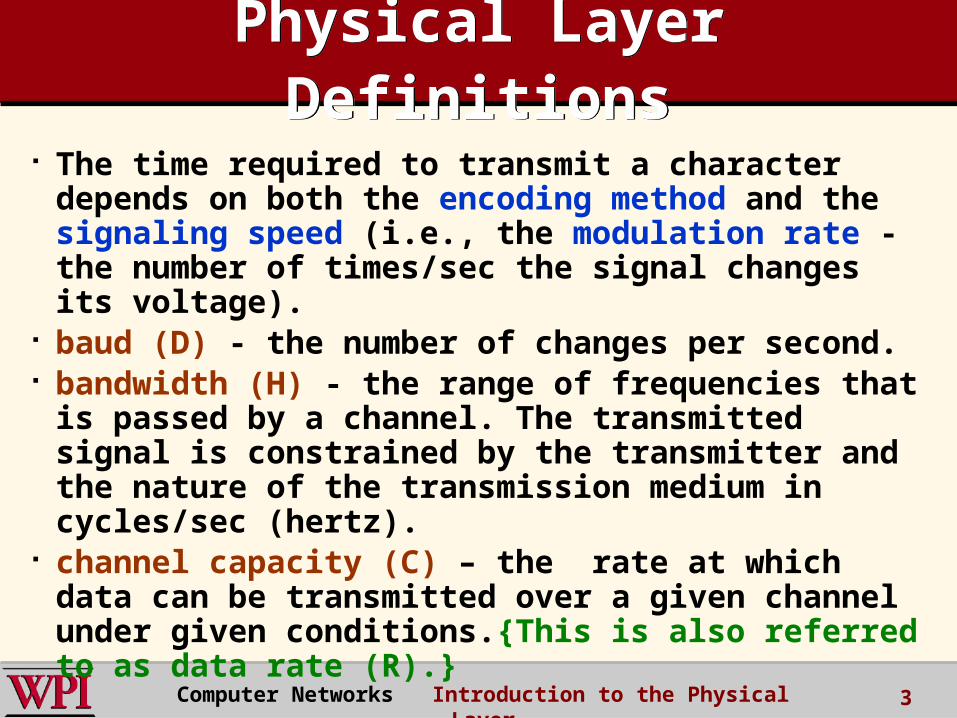
The time required to transmit a character depends on both the encoding method and the signaling speed (i.e., the modulation rate - the number of times/sec the signal changes its voltage).
baud (D) - the number of changes per second. bandwidth (H) - the range of frequencies that
is passed by a channel. The transmitted signal is constrained by the transmitter and the nature of the transmission medium in cycles/sec (hertz).
channel capacity (C) – the rate at which data can be transmitted over a given channel under given conditions.{This is also referred to as data rate (R).}
Computer Networks Introduction to the Physical Layer 3

Modulation RateModulation Rate
Computer Networks Introduction to the Physical Layer 4
DCC 6th Ed.Stallings
modulation rateis doubled
Analog and Digital Signaling
Analog and Digital Signaling
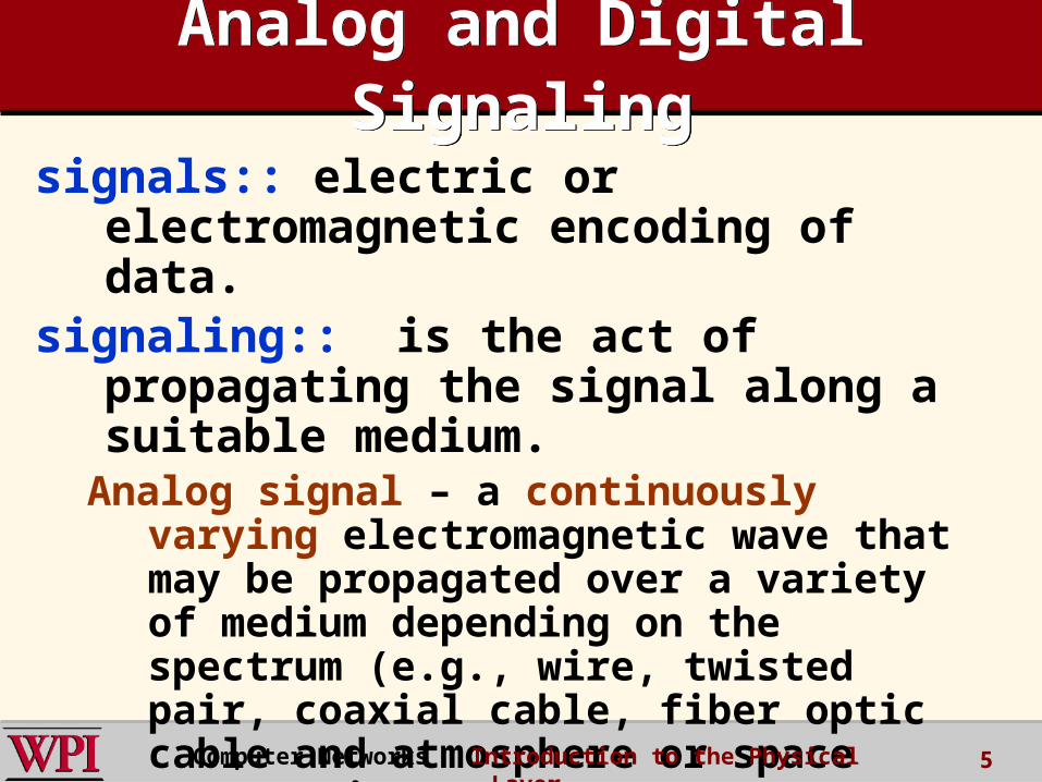
signals:: electric or electromagnetic encoding of data.
signaling:: is the act of propagating the signal along a suitable medium.
Analog signal – a continuously varying electromagnetic wave that may be propagated over a variety of medium depending on the spectrum (e.g., wire, twisted pair, coaxial cable, fiber optic cable and atmosphere or space propagation).Computer Networks Introduction to the Physical Layer 5
Analog and Digital Signaling
Analog and Digital Signaling
digital signal – a sequence of voltage pulses that may be transmitted over a wire medium.
Note – analog signals to represent analog data and digital signals to represent digital data are not the only possibilities.
There is where modems and codecs come into the picture.
Computer Networks Introduction to the Physical Layer 6

Analog vs Digital (three contexts)
Analog vs Digital (three contexts)
Computer Networks Introduction to the Physical Layer 7
DCC 6th Ed.Stallings
modem
codec
Computer Networks Introduction to the Physical Layer 8
MultiplexingMultiplexing
MUXMUX
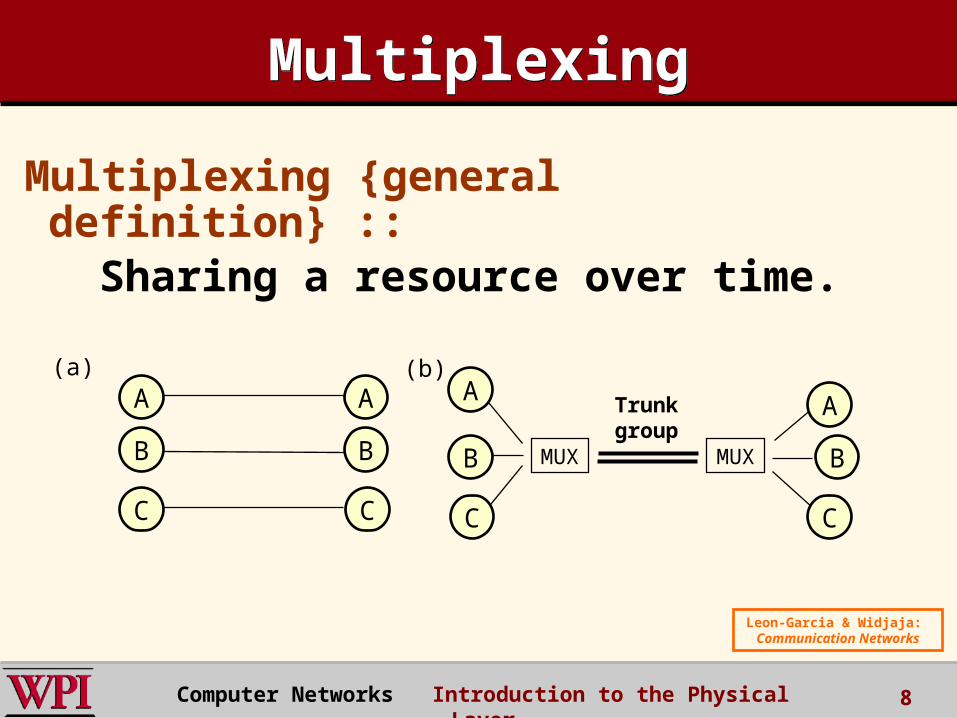
(a) (b)
Trunkgroup
A A AA
BBB B
CC CC
Leon-Garcia & Widjaja: Communication
Networks
Multiplexing {general definition} :: Sharing a resource over time.

Frequency Division Multiplexing (FDM) vs Time Division
Multiplexing (TDM)
Frequency Division Multiplexing (FDM) vs Time Division
Multiplexing (TDM)FDM
frequency
time
TDM
frequency
time
4 users
Example:
K & R
9Computer Networks Introduction to the Physical Layer

Computer Networks Introduction to the Physical Layer 10
Frequency Division Multiplexing
Frequency Division Multiplexing
Figure 2-31. (a) The original bandwidths. (b) The bandwidths raised in frequency. (c) The multiplexed channel.
Tanenbaum

Computer Networks Introduction to the Physical Layer 11
T1 - TDM LinkT1 - TDM Link
TDM: each host gets same slot in revolving TDM frame
Figure 2-33.T1 Carrier (1.544Mbps)
Figure 2-33.T1 Carrier (1.544Mbps) Tanenbaum
TDM:: each host gets a fixed slot in revolving TDM frame
Computer Networks Introduction to the Physical Layer 12
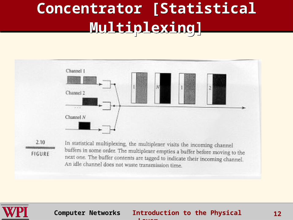
Concentrator [Statistical Multiplexing]
Concentrator [Statistical Multiplexing]
Packet Switching: Statistical Multiplexing
Packet Switching: Statistical Multiplexing
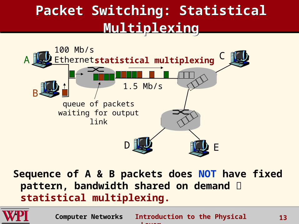
Sequence of A & B packets does NOT have fixed pattern, bandwidth shared on demand statistical multiplexing.
.
A
B
C100 Mb/sEthernet
1.5 Mb/s
D E
statistical multiplexing
queue of packetswaiting for output
link
Computer Networks Introduction to the Physical Layer 13
Computer Networks Introduction to the Physical Layer 14
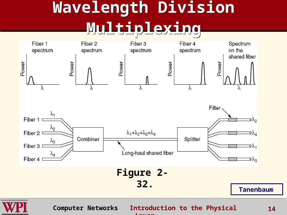
Wavelength Division Multiplexing
Wavelength Division Multiplexing
Wavelength division multiplexing.
Figure 2-32.
Tanenbaum
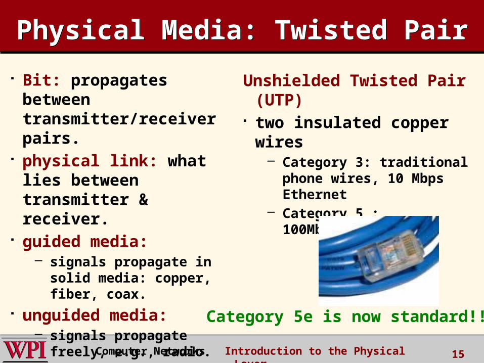
Physical Media: Twisted PairPhysical Media: Twisted Pair
Bit: propagates betweentransmitter/receiver pairs.
physical link: what lies between transmitter & receiver.
guided media: – signals propagate in solid
media: copper, fiber, coax. unguided media:
– signals propagate freely, e.g., radio.
Unshielded Twisted Pair (UTP)
two insulated copper wires
– Category 3: traditional phone wires, 10 Mbps Ethernet
– Category 5 : 100Mbps Ethernet
Computer Networks Introduction to the Physical Layer 15
Category 5e is now standard!!
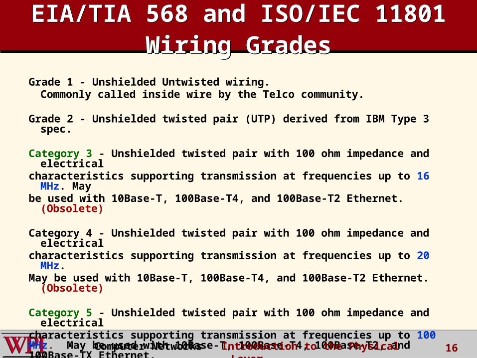
Grade 1 - Unshielded Untwisted wiring.Commonly called inside wire by the Telco community.
Grade 2 - Unshielded twisted pair (UTP) derived from IBM Type 3 spec.
Category 3 - Unshielded twisted pair with 100 ohm impedance and electrical
characteristics supporting transmission at frequencies up to 16 MHz. May
be used with 10Base-T, 100Base-T4, and 100Base-T2 Ethernet. (Obsolete)
Category 4 - Unshielded twisted pair with 100 ohm impedance and electrical
characteristics supporting transmission at frequencies up to 20 MHz.May be used with 10Base-T, 100Base-T4, and 100Base-T2 Ethernet.
(Obsolete)
Category 5 - Unshielded twisted pair with 100 ohm impedance and electrical
characteristics supporting transmission at frequencies up to 100 MHz. May be used with 10Base-T, 100Base-T4, 100Base-T2, and 100Base-TX Ethernet.May support 1000Base-T, but cable should be tested. (Superceded by
Cat5e)
EIA/TIA 568 and ISO/IEC 11801 Wiring Grades
EIA/TIA 568 and ISO/IEC 11801 Wiring Grades
16Computer Networks Introduction to the Physical Layer

“Modern” Twisted Pair“Modern” Twisted Pair
DCC 9th Ed.Stallings
17Computer Networks Introduction to the Physical Layer

Physical Media: Coaxial Cable and Optical Fiber
Physical Media: Coaxial Cable and Optical Fiber
Coaxial cable: two concentric
copper conductors bidirectional baseband:
– single channel on cable– legacy Ethernet
broadband:– multiple channels on
cable– HFC
Fiber optic cable:• glass fiber carrying light
pulses, each pulse a bit• high-speed operation:
• point-to-point transmission (e.g., 10’s-100’s Gps)
• low error rate: repeaters spaced far apart ; immune to electromagnetic noise.
Computer Networks Introduction to the Physical Layer 18

Physical Media: Radio Signals
Physical Media: Radio Signals
signal carried in electromagnetic spectrum.
no physical “wire” bidirectional propagation
environment effects:
– reflection – obstruction by objects– interference
Radio link types:• terrestrial microwave
• e.g. up to 45 Mbps channels
• LAN (e.g., Wifi)• 11Mbps, 54 Mbps,
200Mbps
• wide-area (e.g., cellular)• 4G cellular: ~ 100 Mbps
• satellite• Kbps to 45Mbps channel
(or multiple smaller channels)
• 270 msec end-end delay• geosynchronous versus
low altitudeComputer Networks Introduction to the Physical Layer 19
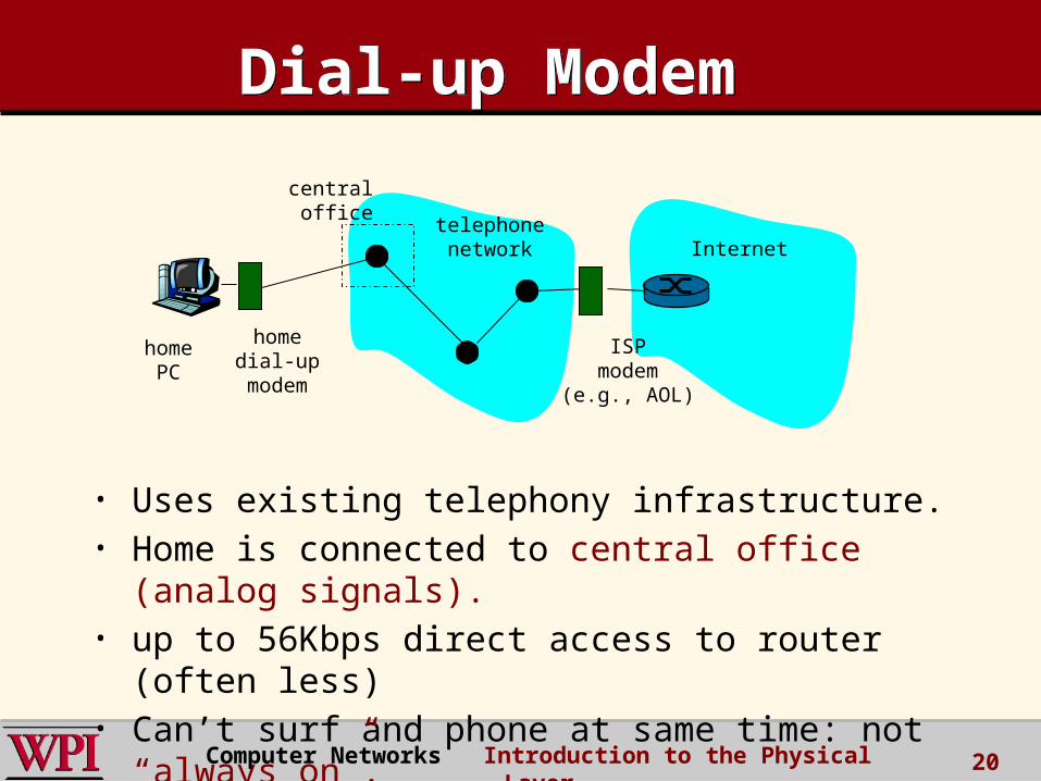
telephonenetwork Internet
homedial-upmodem
ISPmodem
(e.g., AOL)
homePC
central office
• Uses existing telephony infrastructure.• Home is connected to central office (analog
signals).• up to 56Kbps direct access to router (often less)• Can’t surf and phone at same time: not “always
on”.
Dial-up ModemDial-up Modem
Computer Networks Introduction to the Physical Layer 20
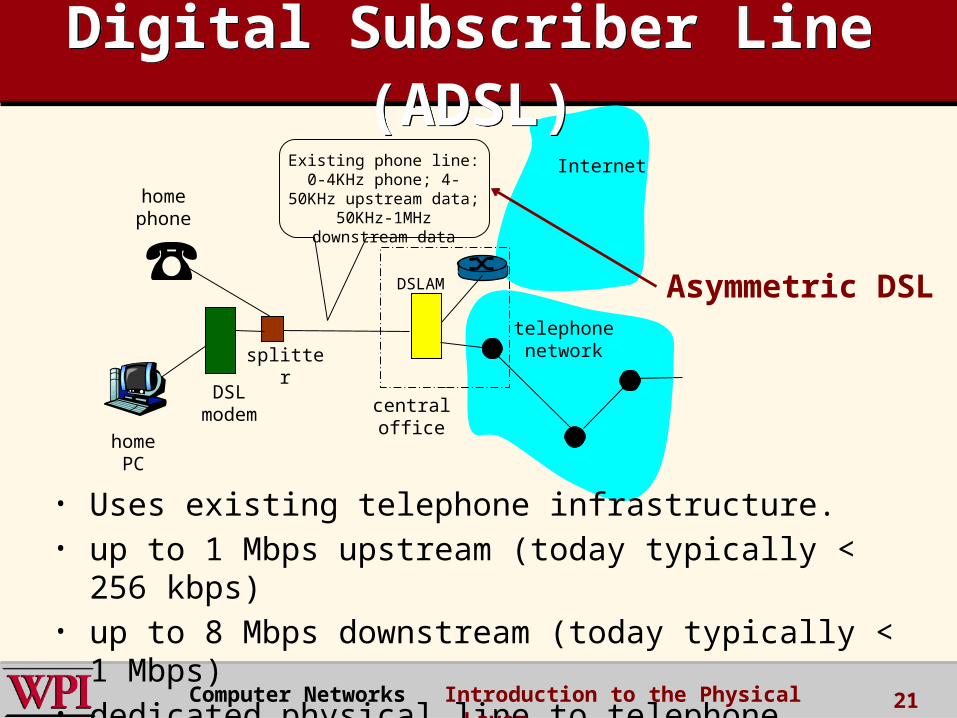
telephonenetwork
DSLmodem
homePC
homephone
Internet
DSLAM
Existing phone line:0-4KHz phone; 4-50KHz
upstream data; 50KHz-1MHz downstream data
splitter
centraloffice
Digital Subscriber Line (ADSL)
Digital Subscriber Line (ADSL)
• Uses existing telephone infrastructure.• up to 1 Mbps upstream (today typically < 256
kbps)• up to 8 Mbps downstream (today typically < 1
Mbps)• dedicated physical line to telephone central office
Computer Networks Introduction to the Physical Layer 21
Asymmetric DSL

Comparison of xDSL Alternatives
Comparison of xDSL Alternatives
DCC 9th Ed.Stallings
22Computer Networks Introduction to the Physical Layer
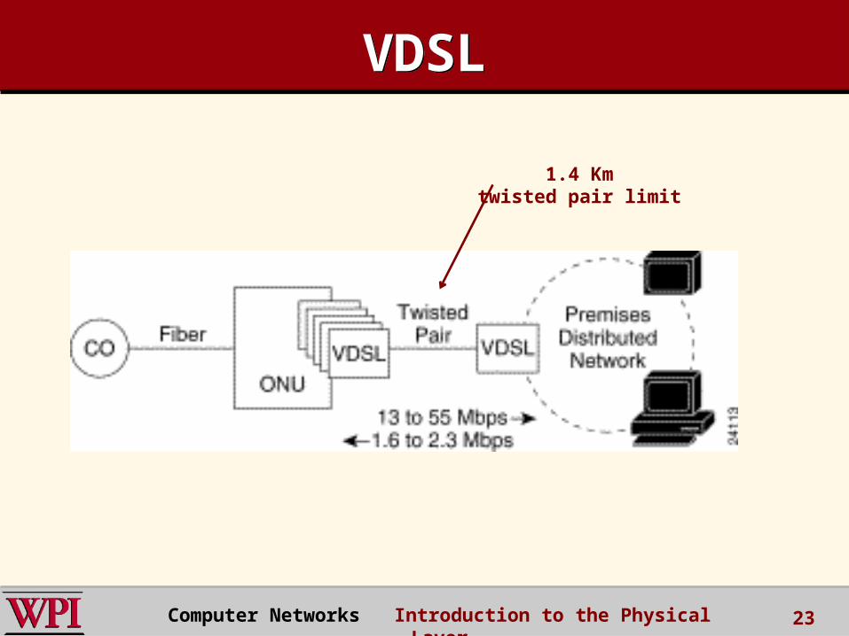
VDSLVDSL
23
1.4 Kmtwisted pair limit
Computer Networks Introduction to the Physical Layer
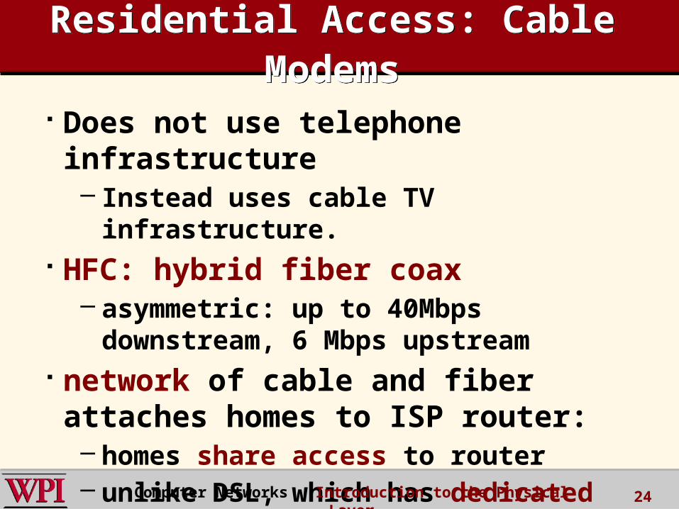
Residential Access: Cable Modems
Residential Access: Cable Modems
Does not use telephone infrastructure– Instead uses cable TV infrastructure.
HFC: hybrid fiber coax– asymmetric: up to 40Mbps downstream, 6
Mbps upstream network of cable and fiber attaches homes to ISP router:– homes share access to router – unlike DSL, which has dedicated access.
Computer Networks Introduction to the Physical Layer 24
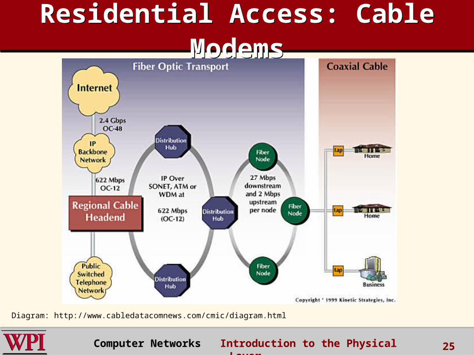
Residential Access: Cable Modems
Residential Access: Cable Modems
Diagram: http://www.cabledatacomnews.com/cmic/diagram.html
Computer Networks Introduction to the Physical Layer 25
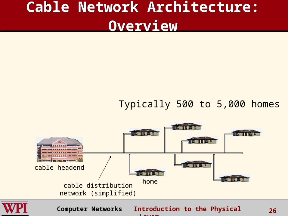
Cable Network Architecture: Overview
Cable Network Architecture: Overview
home
cable headend
cable distributionnetwork (simplified)
Typically 500 to 5,000 homes
Computer Networks Introduction to the Physical Layer 26
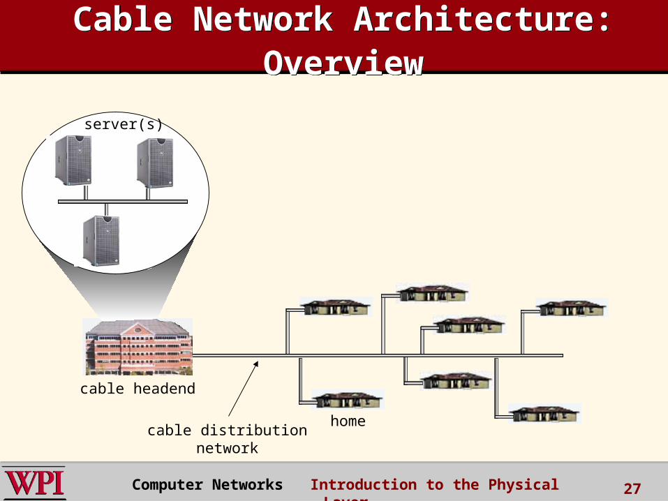
home
cable headend
cable distributionnetwork
server(s)
Computer Networks Introduction to the Physical Layer 27
Cable Network Architecture: Overview
Cable Network Architecture: Overview
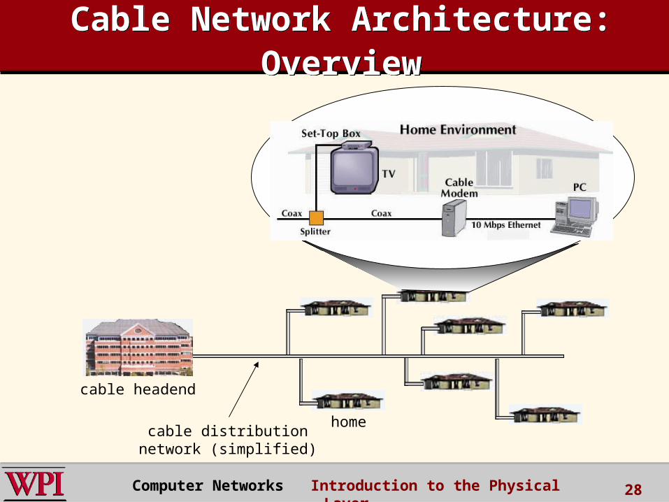
home
cable headend
cable distributionnetwork (simplified)
Computer Networks Introduction to the Physical Layer 28
Cable Network Architecture: Overview
Cable Network Architecture: Overview

Cable Network Architecture: Overview
Cable Network Architecture: Overview
home
cable headend
cable distributionnetwork
Channels
VIDEO
VIDEO
VIDEO
VIDEO
VIDEO
VIDEO
DATA
DATA
CONTROL
1 2 3 4 5 6 7 8 9
FDM
Computer Networks Introduction to the Physical Layer 29

30
DOCSIS (Data-Over-CableService Interface Specification)
DOCSIS (Data-Over-CableService Interface Specification)
Computer Networks Introduction to the Physical Layer
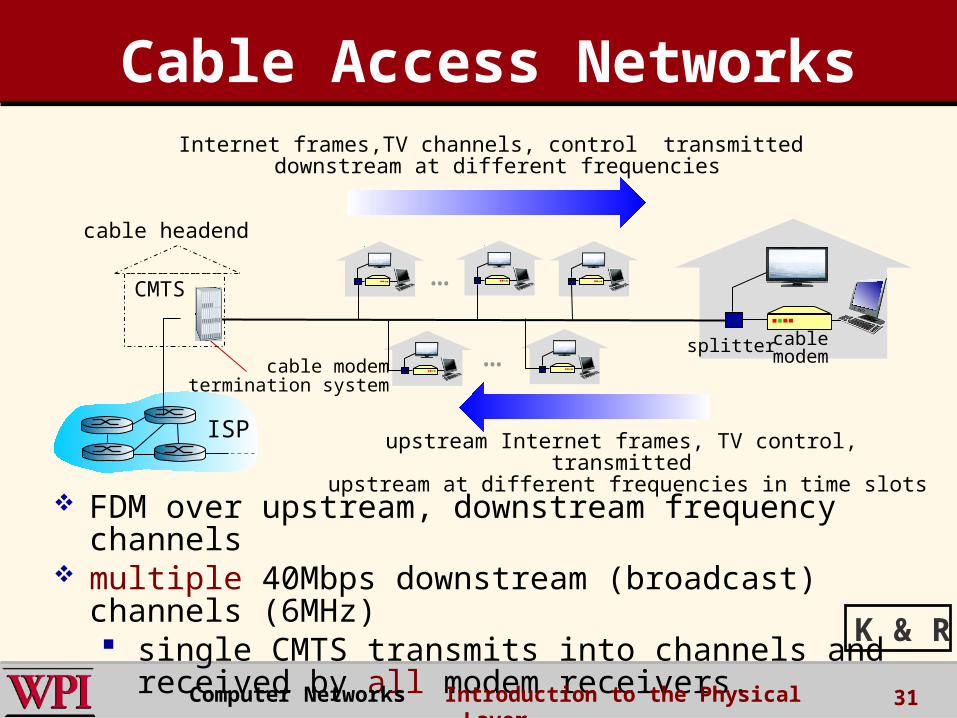
cable headend
CMTS
ISP
cable modemtermination system
FDM over upstream, downstream frequency channels
multiple 40Mbps downstream (broadcast) channels (6MHz) single CMTS transmits into channels and
received by all modem receivers.
cablemodem
splitter
…
…
Internet frames,TV channels, control transmitted downstream at different frequencies
upstream Internet frames, TV control, transmitted upstream at different frequencies in time slots
Cable Access Networks
31
K & R
Computer Networks Introduction to the Physical Layer

multiple 30 Mbps upstream channels (6.4MHz) TDM-like upstream mini-slots
MAP frame forInterval [t1, t2]
Residences with cable modems
Downstream channel i
Upstream channel j
t1 t2
Assigned minislots containing cable modemupstream data frames
Minislots containing minislots request frames
cable headend
CMTS
32
DOCSIS Cable Access Networks
DOCSIS Cable Access Networks
K & R
Computer Networks Introduction to the Physical Layer

OLT
central office
opticalsplitter
ONT
opticalfiber
opticalfibers
Internet
Fiber to the HomeFiber to the Home
Optical links from central office to the home
Two competing optical technologies: – Passive Optical network (PON) – Active Optical Network (AON)
Higher Internet rates. Fiber also carries television and phone services.
Computer Networks Introduction to the Physical Layer 33
ONT
ONT
Verizon FIOS

AON Active Optical Network Uses electrical powered
switches More range Less reliable
PON Passive Optical Network Optical splitters do not
need electrical power. Hard to isolate failure Transmission speed may
be slower during peak hours.
Wikipedia
34Computer Networks Introduction to the Physical Layer

100 Mbps
100 Mbps
100 Mbps1 Gbps
server
Ethernetswitch
Institutionalrouter
To Institution’sISP
Ethernet Internet AccessEthernet Internet Access
Typically used in companies, universities, etc
• 10 Mbs, 100Mbps, 1Gbps, 10Gbps Ethernet• Today, end systems typically connect into
Ethernet switch.Computer Networks Introduction to the Physical Layer 35
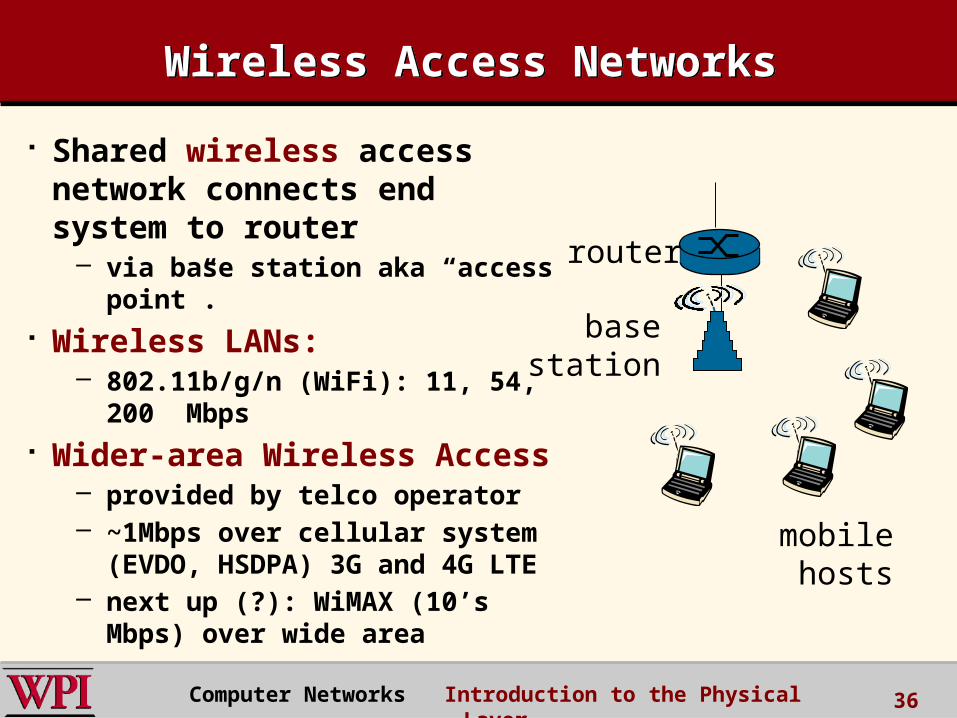
Wireless Access NetworksWireless Access Networks
Shared wireless access network connects end system to router
– via base station aka “access point”.
Wireless LANs:– 802.11b/g/n (WiFi): 11, 54, 200
Mbps Wider-area Wireless Access
– provided by telco operator– ~1Mbps over cellular system
(EVDO, HSDPA) 3G and 4G LTE– next up (?): WiMAX (10’s Mbps)
over wide area
basestation
mobilehosts
router
Computer Networks Introduction to the Physical Layer 36
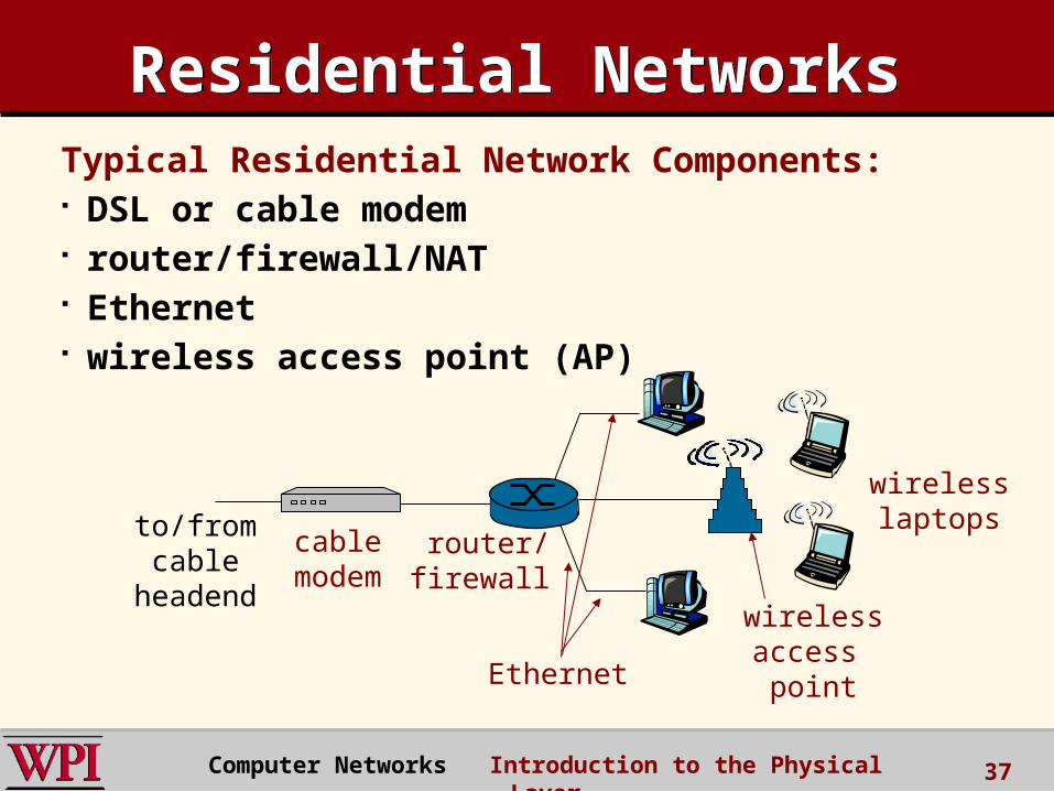
Residential NetworksResidential NetworksTypical Residential Network Components: DSL or cable modem router/firewall/NAT Ethernet wireless access point (AP)
wirelessaccess point
wirelesslaptops
router/firewall
cablemodem
to/fromcable
headend
Ethernet
Computer Networks Introduction to the Physical Layer 37
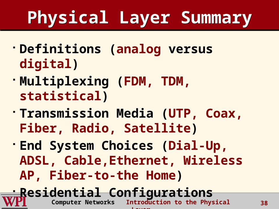
Physical Layer SummaryPhysical Layer Summary
Definitions (analog versus digital) Multiplexing (FDM, TDM, statistical)
Transmission Media (UTP, Coax, Fiber, Radio, Satellite)
End System Choices (Dial-Up, ADSL, Cable,Ethernet, Wireless AP, Fiber-to-the Home)
Residential Configurations
Computer Networks Introduction to the Physical Layer 38