Compressive Strength of Solid Clay Brick Masonry ... · Table 1 shows the data for bricks and...
10
Structural Analysis of Historical Constructions, New Delhi 2006 P.B. Lourenço, P. Roca, C. Modena, S. Agrawal (Eds.) 1 INTRODUCTION The large number of ancient masonry structures, arch bridges, tunnels, historical and ordinary buildings puts forward the need for their structural assessment. Whatever the mechanical model for the structure and the material constitutive model, the assessment procedure asks some me- chanical parameter to be identified, at least the compressive strength f c and, sometimes, the elas- tic modulus E. The available experimental and theoretical approaches present both advantages and problems that make their application somehow troublesome. The experimental approach to existing masonry relies on NDT and MDT tests, facing some conceptual deficiency for some technique, a limited data base for the test calibration and large errors due to specific technical problems for other techniques. For small diameter drillings, i.e. 70-90 mm, the core does not reproduce the brickwork bond and core testing according to well established techniques for concrete produce unreliable results. Flat jacks (ASTM, 1991) ask highly skilled workmanship and a precise, and expensive, procedure to provide reliable results. Other NDT approaches proposed, such as radar and sonic testing (Colla et al., 1998, Bensalem et al., 1998, Valle et al., 1998) still need a detailed calibration and do not seem to be able to provide quantitative estimates of the brickwork mechanical parameters. Deformation and failure theories, on the other hand, have been developed since the late six- ties with the aim of defining constitutive models and failure criteria based on the mechanical properties of bricks and mortar (Hilsdorf, 1969, Francis, 1971, Khoo and Hendry, 1973, Shrive, 1987, among the others). Due to the stress concentrations induced by masonry intrinsic inho- mogeneity, these theoretical approaches do not give fully satisfactory estimates neither of the measured compressive strength nor of the elastic modulus. In this work two experimental procedures for solid clay brickwork are discussed and par- tially calibrated. A) Due to the basic mechanics of brickwork collapse, i.e. transversal traction in the bricks, sclerometer tests on bricks may provide a first level estimate of brickwork compres- sive strength. B) Compressive tests on large diameter cylinders (φ = 150 mm) loaded on the lat- eral surface have been proposed by UIC (1995) allow the brickwork bond to be represented and the load to be applied in the proper direction. The results show that both these techniques are Compressive Strength of Solid Clay Brick Masonry: Calibration of Experimental Tests and Theoretical Issues Antonio Brencich and Enrico Sterpi University of Genoa, Department of Civil and Geotechnical Engineering, Genoa, Italy ABSTRACT: The assessment procedures for masonry structures ask for (at least) the compres- sive strength of the material to be defined. Several theoretical approaches, based on the charac- teristics of bricks and mortar, and experimental techniques are available, but only a comprehen- sive approach allows a rational definition of the material strength. In this paper, the calibration of two procedures, Schmidt Hammer tests for a first level evaluation of masonry strength and compressive tests on large diameter cylinders drilled from brickwork, is discussed. While the er- ror of the first technique appears to be quite relevant, the latter MDT approach seems to be promising provided the data base for calibration is large enough.
Transcript of Compressive Strength of Solid Clay Brick Masonry ... · Table 1 shows the data for bricks and...

Structural Analysis of Historical Constructions, New Delhi 2006P.B. Lourenço, P. Roca, C. Modena, S. Agrawal (Eds.)
1 INTRODUCTION
The large number of ancient masonry structures, arch bridges, tunnels, historical and ordinary buildings puts forward the need for their structural assessment. Whatever the mechanical model for the structure and the material constitutive model, the assessment procedure asks some me-chanical parameter to be identified, at least the compressive strength fc and, sometimes, the elas-tic modulus E. The available experimental and theoretical approaches present both advantages and problems that make their application somehow troublesome.
The experimental approach to existing masonry relies on NDT and MDT tests, facing some conceptual deficiency for some technique, a limited data base for the test calibration and large errors due to specific technical problems for other techniques. For small diameter drillings, i.e. 70-90 mm, the core does not reproduce the brickwork bond and core testing according to well established techniques for concrete produce unreliable results. Flat jacks (ASTM, 1991) ask highly skilled workmanship and a precise, and expensive, procedure to provide reliable results. Other NDT approaches proposed, such as radar and sonic testing (Colla et al., 1998, Bensalem et al., 1998, Valle et al., 1998) still need a detailed calibration and do not seem to be able to provide quantitative estimates of the brickwork mechanical parameters.
Deformation and failure theories, on the other hand, have been developed since the late six-ties with the aim of defining constitutive models and failure criteria based on the mechanical properties of bricks and mortar (Hilsdorf, 1969, Francis, 1971, Khoo and Hendry, 1973, Shrive, 1987, among the others). Due to the stress concentrations induced by masonry intrinsic inho-mogeneity, these theoretical approaches do not give fully satisfactory estimates neither of the measured compressive strength nor of the elastic modulus.
In this work two experimental procedures for solid clay brickwork are discussed and par-tially calibrated. A) Due to the basic mechanics of brickwork collapse, i.e. transversal traction in the bricks, sclerometer tests on bricks may provide a first level estimate of brickwork compres-sive strength. B) Compressive tests on large diameter cylinders (φ = 150 mm) loaded on the lat-eral surface have been proposed by UIC (1995) allow the brickwork bond to be represented and the load to be applied in the proper direction. The results show that both these techniques are
Compressive Strength of Solid Clay Brick Masonry: Calibrationof Experimental Tests and Theoretical Issues
Antonio Brencich and Enrico Sterpi University of Genoa, Department of Civil and Geotechnical Engineering, Genoa, Italy
ABSTRACT: The assessment procedures for masonry structures ask for (at least) the compres-sive strength of the material to be defined. Several theoretical approaches, based on the charac-teristics of bricks and mortar, and experimental techniques are available, but only a comprehen-sive approach allows a rational definition of the material strength. In this paper, the calibration of two procedures, Schmidt Hammer tests for a first level evaluation of masonry strength and compressive tests on large diameter cylinders drilled from brickwork, is discussed. While the er-ror of the first technique appears to be quite relevant, the latter MDT approach seems to be promising provided the data base for calibration is large enough.
promising tools for the characterization of existing solid clay brickwork.
2 TESTING PROCEDURES 2.1 Sclerometer tests The Schmidt Hammer is a well known test for the estimation of concrete strength; even though well calibrated on concrete by several decades of worldwide use (Malhotra and Carino, 1991), this test is affected by an error as large as ±10% due to the measuring principle.
The collapse mechanism of solid clay brickwork is due to transversal traction in the brick and cracks are originated in the bricks collinear to the loading direction; therefore, the Schmidt Hammer could provide an estimate of the compressive strength also for solid clay brickwork. This approach is not applicable to other types of masonry.
The large number of brickwork types, along with a limited experimental data base, makes it difficult to give an estimate of the error of this tool, and this is a limit to its professional use. Presently, it is used for a rough estimation of brickwork uniformity (D.o.A., 1992). Due to the differences in the surface hardness of bricks, very low for degraded materials and rather high for modern bricks, the concrete hammer (type N, impact energy = 2.207 N/m) cannot be used for degraded materials; a reduced energy version (type L, impact energy = 0.735 N/m), used in rock engineering, may be used for solid clay brickwork. Both have been used in this work.
2.2 Compressive tests on cylinders The UIC 778-3R guidelines (1995) ask a 150 mm diameter cylinder to be drilled so as to repro-duce the basic brickwork bond, Fig. 1. The specimen is loaded on the lateral surface, i.e. in the same way brickwork is loaded in the original structure, recording both the vertical and horizon-tal displacements. The compressive strength of brickwork is simply assumed as the ratio be-tween the collapse load and the horizontal cross section, Fig. 2, fc = Fcoll /φ l, being fc the com-pressive strength, Fcoll the load at collapse, φ and l the cylinder diameter and length; the characteristic value of the compressive strength is assumed as 1.1 times the minimum value.
The secant elastic modulus is calculated referring to a reduced section 0.75φ l and to loads at 1/10th (F0.1) and 1/2 (F0.5) of the limit load:
εh = uh /φ, εv = uv /φ (2.a,b)
∆εh0.1-0.5
= u h0.5
- u h0.1 /φ, ∆εv
0.1-0.5 = u v
0.5 - u v
0.1 /φ (3.a,b)
E = 4(F0.5 - F0.1) / 3( u v
0.5 - u v
0.1 )l, v = u h0.5
- u h0.1 / u v
0.5 - u v
0.1, (4.a,b) being εv and εh the vertical and horizontal strains and uv and uh the related displacements.
Figure 1 : Test arrangement Figure 2 : Detail of test arrangement
uv
uh LVDT 3
LVDT 2(rear)
LVDT 1
LVDT 4
Load cell
Fixed base
Cylindrical hinge
Moving end
758 Structural Analysis of Historical Constructions

A. Brencich and E. Sterpi 759
The testing setup is presented in Fig. 2; minor details are omitted for simplicity. The load measuring device is a C5 class HBM-RTN load cell with a 0.01% precision and is located in-between the upper plate and the testing machine. The upper and lower plates are connected to the testing frame through cylindrical hinges that allow the load line to be precisely identified. The relative displacements are measured by means of LVDTs with a 0.001mm precision. The displacement of the upper plate is measured at the two ends of the specimen (LVDTs n. 1 and 2), while the lateral ones are recorded at the centre of the cylinder (LVDTs n. 3 and 4), so that uv, eq. (2) and (3), is directly the sum of devices 3 and 4. The moving end of the machine, and the whole load process, is displacement controlled, the load being measured by the load cell. A 2 mm thick lead sheet between the specimen and the loading plates was used.
Table 1 : Mechanical characteristics of bricks and mortars.
Av. value
[MPa] n. of
samples C.o.V. Char. Value
[MPa] (Gaussian) Char. /
Average Compressive strength – direct 20.2 20 17% 13.6 0.67 Tensile strength – TPB 5.0 10 6.5% 4.30 0.86
Bric
k
Elastic modulus 15930 20 32% 5930 0.38 Compressive strength – direct 11.9 25 3% 11.5 0.97 Tensile strength – TPB 3.8 13 8% 3.5 0.92
M –
1
Elastic modulus 1520 25 3% 2440 0.97 Compressive strength – direct 8.9 32 5% 8.5 0.96 Tensile strength – TPB 3.3 16 4% 3.2 0.97
M –
2
Elastic modulus 1300 32 17% 1080 0.83
3 TESTING PROGRAM AND RESEARCH AIMS
The two experimental procedures can be calibrated by comparison of the measured data with the compressive strength of the brickwork, obtained through concentric load tests on prisms of the same masonry. For this reason, not only a large number of tests has been performed in order to provide a reasonably large data base, but also couples of specimens have been produced at the same moment, one for drilling the cylinder and the other for direct testing, in order to compare data coming from the same brickwork produced in the same moment, by the same workmanship and in the same hygrometric conditions. For these reasons, tests are compared two-by-two: test on cylinder vs. direct compression test on concentrically loaded prisms, Fig. 3.
Table 1 shows the data for bricks and mortars according to pr-EN 1052-1, 771-1, 772-1. Mortar 1 (M-1, cement-lime) and mortar 2 (M-2, white cement – lime) are different commercial Italian products for which the producer did not provide the exact proportions.
Direct concentric compression 150mm in diameter cylinder is drilled UIC test
Figure 3 : Identical specimens for: (a) direct concentric compression; (b) UIC (1995) tests.
(a) (b)
4 TEST RESULTS 4.1 Schmidt Hammer
The tests have been performed according to ASTM C 805 using both the type N (for con-crete) and the type L (for rock) hammers. The measured data (average of 22 measurements) have been found affected by very low values of c.o.v., Table 2.
4.2 Cylinders
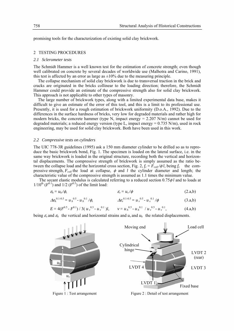
Fig.s 4 and 5 show the stress-strain curves and the collapse mechanisms of the tested specimens; Table 3 summarizes the experimental data (Prism 3 for Mortar 1 is missing because of technical problems during the tests). Stresses are calculated as suggested by UIC, i.e. assuming the peak load to be divided on the whole horizontal section φ l.
Table 2 : Sclerometer test results. See Table 3 for brickwork strength. Mortar – 1 brickwork <fc> = 12.8 MPa Mortar – 2 brickwork <fc>= 12.7 MPa rebound σ C.o.V. rebound σ C.o.V.
Type N 35 0.45 1.3% 34 0.48 1.4% Type L 28 0.71 2.6% 28 0.63 2.2%
Table 3: Summary of the experimental data (cylinder tests).
Mortar – 1 Prism 1 Cylinder 1 Prism 2 Cylinder 2 Prism 3 Cylinder 3
fc [MPa] 12.1 7.6 10.6 5.7 / 5.8 E [MPa] 20550 6820 15560 5140 / 4070
fc prism/cylinder 1.6 1.9 / E prism/cylinder 3.0 2.8 /
Mortar – 2 Prism 1 Cylinder 1 Prism 2 Cylinder 2 Prism 3 Cylinder 3
fc [MPa] 9.6 5.6 8.2 5.3 11.5 5.6 E [MPa] 12900 4000 9500 3400 19300 5080
fc prism/cylinder 1.7 1.6 2.1 E prism/cylinder 3.2 2.8 3.7
Mortar - 1
0
2
4
6
8
10
12
0 0,5 1 1,5 2 2,5 3 3,5 4 4,5 5
Vertical strain %
Verti
cal S
tress
[M
Pa]
Cylinder-1 Cylinder-2Cylinder-3 Prism-1Prism-2 Prism-3
(a)
a)
760 Structural Analysis of Historical Constructions

A. Brencich and E. Sterpi 761
Mortar - 2
0
2
4
6
8
10
12
0 0,5 1 1,5 2 2,5 3 3,5 4 4,5 5
Vertical strain %
Verti
cal s
tress
[M
Pa]
Cylinder-1 Cylinder-2Cylinder-3 Prism-1Prism-2
(b)
Figure 4 : Stress-strain curves for the tested specimens: (a) mortar – 1; (b) mortar – 2.
Fig.s 4 show that the overall response of prisms and cylinders have similarities and differ-ences: the peak load and the (elastic) initial stiffness are rather different but the ratio between the cylindrical tests and the prism data seem to be quite constant, Table 3:
fcprism≅ 1.8 fc
cyl, and E prism≅ 3 E cyl (5.a, b)
Figure 5 : Typical crack pattern at: (a) 80% of the maximum load; (b) end of the test; (c), (d) and (e) typical collapse mechanisms: opening of the vertical joint and splitting of the lateral part of the cylinder (after peak
load).
Besides, both the tests show significant inelastic strains, more pronounced for cylinder tests, and rather similar post-peak descending branches. Fig. 5a shows the typical collapse mechanism at 80% of the peak load when the central vertical mortar joint cracks along its whole length, out-lining that inelastic strains have already been developed; Fig. 5b displays the collapse mecha-nism at collapse; Fig.s 5c-5e show the final stage of the specimen: (i) a crack is found in the ver-tical joint, at the mortar/brick interface; (ii) the lateral parts of the specimen are detached, the phenomenon being induced by the ends of the loading plates, Fig. 5b.
(a) (b)
(c) (d) (e)
crack crack
b)

762 Structural Analysis of Historical Constructions
5 NUMERICAL APPROACH: FEM MODELS
FEM models may help in understanding the collapse mechanism of the cylinders: the evolution of cracking in the specimen should be similar to that of brickwork for the test to be reliable. Since masonry undergoes large cracking far before the collapse load is reached, FEM models fail in predicting the ultimate load and can be used to understand the activation of cracking and the first steps of its evolution only. In the following, the main results of FEM analysis (Brencich et al., 2004) for a brickwork similar to the one tested in this work are briefly summarized with the aim of outlining the evolution of cracking at the beginning of the inelastic phase, repre-sented in Fig. 5a.
Fig. 6 shows the evolution of cracking inside the cylinder as the load increases. It can be clearly recognized the gradual activation of the central core of brickwork that had been already detected during the tests; the sudden increase of the lateral displacement seems to be due to the opening of the central joint, Fig. 5b.
The distribution of the vertical and horizontal stresses at 80% of the peak load is displayed in Fig. 7. The vertical stresses, Fig. 7a, are not distributed on the whole cross section but are con-centrated in a sand-glass shaped central core large as much as 3/5th of the whole cross section; the stress distribution is not uniform being affected by the cracking of the vertical joint. Fig. 7b shows strong concentrations of horizontal stress in the upper and lower bricks and at the edges of the loading plates, which explains the observed crack patterns and the detachment of the lat-eral parts of the cylinders (Fig.s 5c-5e).
Figure 6 : Crack pattern evolution during the load process (see Figure 5)
Figure 7 : (a) Vertical and (b) horizontal stresses [MPa] at 80% of the peak load.
-15.3 -13.6 -11.9 -10.2 -8.5 -6.8
-3.4 -1.7 0
-5.1
Step 4 Step 5 Step 7
Step 8 Last
+1.8
-3.6 -3.0 -2.4-1.8-1.2 -0.6
+0.6 +1.2
0
(a) (b)
Loading plates - edge
Loading plates - edge

A. Brencich and E. Sterpi 763
Figure 8 : Cracking of masonry prisms at 80% of the peak load: (a) and (b) lateral views; (c) detail. The FEM model, although not able of reproducing the entire loading process of the cylinder
up to collapse, helps in understanding the onset of cracking in the specimen. Fig. 8 shows the crack pattern approximately at 80% of the peak load for the tested prisms: cracking clearly originates from the central mortar joint. Some ongoing numerical analysis (Corradi, 2006) sug-gests that this is caused by a concentration of tensile stresses in the brick, in the part close to the vertical joint, due to the brick/mortar elastic mismatch. The comparison of the crack pattern of Fig.s 5, 6 and 8, with the results of the numerical analysis shows that the brickwork collapse mechanism is reproduced by the large diameter cores but for the stress concentrations due to the loading plates, Fig. 7b. Besides, FEM models reproduce the experimental outcomes with rea-sonable approximation, so that the suggested calibration formulas, eq. (5), can be considered a reliable estimate of the actual brickwork compressive strength. Further details of the FEM analysis can be found in (Brencich et al., 2004).
6 COMPARISON AND DISCUSSION
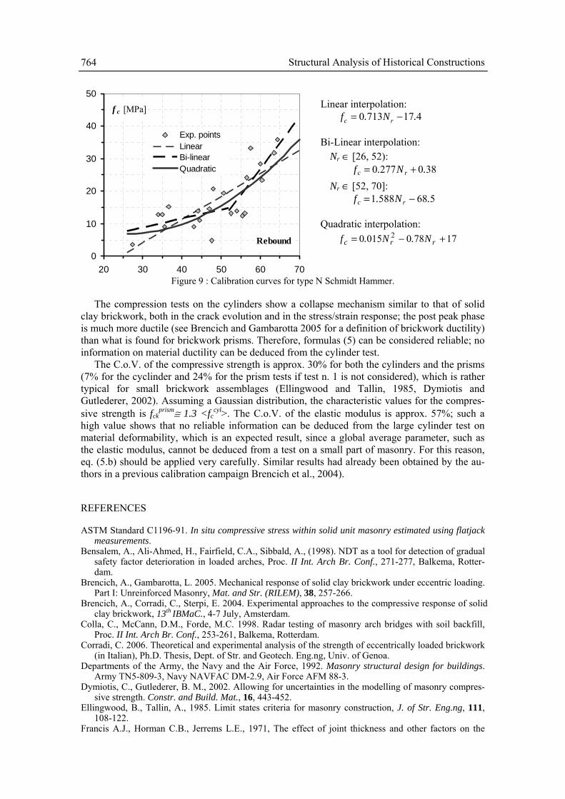
The couple of data obtained in this research widen the data base used for the calibration of the sclerometer for solid clay brickwork; Figure 9 shows the calibration curve for type N Schmidt Hammer (solid clay brickwork only) based on the data base from (D.o.A, 1992) and updated by means of the data of the present work and of other tests performed at the authors’ Department (Trucco, 2004). The standard approach assumes a linear interpolation even though bi-linear and parabolic curves seem to fit better the experimental results, i.e. an increase of brickwork strength for high rebound values. Besides, a linear interpolation shows a vanishing strength for non-vanishing rebound values, which seems quite unjustified. Nevertheless, even though the calibration curves rely on a relatively wide number of laboratory data, the use of the Schmidt Hammer for real brickwork should be very careful and should be better confirmed by some di-rect MDT test. Figure 9 shows, for example, that the actual compressive strength might be some ±25% the value estimated by the Schmidt Hammer. Some kind of structure with high levels of workmanship, such as masonry bridges, better fit the laboratory conditions than ordinary struc-tures.
(a) (b) (c)
0
10
20
30
40
50
20 30 40 50 60 70
Rebound
f c [MPa]
Exp. pointsLinearBi-linearQuadratic
Linear interpolation: 4177130 .N.f rc −=
Bi-Linear interpolation: Nr ∈ [26, 52):
3802770 .N.f rc += Nr ∈ [52, 70]:
5685881 .N.f rc −=
Quadratic interpolation: 177800150 2 +−= rrc N.N.f
Figure 9 : Calibration curves for type N Schmidt Hammer.
The compression tests on the cylinders show a collapse mechanism similar to that of solid clay brickwork, both in the crack evolution and in the stress/strain response; the post peak phase is much more ductile (see Brencich and Gambarotta 2005 for a definition of brickwork ductility) than what is found for brickwork prisms. Therefore, formulas (5) can be considered reliable; no information on material ductility can be deduced from the cylinder test. The C.o.V. of the compressive strength is approx. 30% for both the cylinders and the prisms (7% for the cyclinder and 24% for the prism tests if test n. 1 is not considered), which is rather typical for small brickwork assemblages (Ellingwood and Tallin, 1985, Dymiotis and Gutlederer, 2002). Assuming a Gaussian distribution, the characteristic values for the compres-sive strength is fck
prism≅ 1.3 <fccyl>. The C.o.V. of the elastic modulus is approx. 57%; such a
high value shows that no reliable information can be deduced from the large cylinder test on material deformability, which is an expected result, since a global average parameter, such as the elastic modulus, cannot be deduced from a test on a small part of masonry. For this reason, eq. (5.b) should be applied very carefully. Similar results had already been obtained by the au-thors in a previous calibration campaign Brencich et al., 2004).
REFERENCES
ASTM Standard C1196-91. In situ compressive stress within solid unit masonry estimated using flatjack measurements.
Bensalem, A., Ali-Ahmed, H., Fairfield, C.A., Sibbald, A., (1998). NDT as a tool for detection of gradual safety factor deterioration in loaded arches, Proc. II Int. Arch Br. Conf., 271-277, Balkema, Rotter-dam.
Brencich, A., Gambarotta, L. 2005. Mechanical response of solid clay brickwork under eccentric loading. Part I: Unreinforced Masonry, Mat. and Str. (RILEM), 38, 257-266.
Brencich, A., Corradi, C., Sterpi, E. 2004. Experimental approaches to the compressive response of solid clay brickwork, 13th IBMaC., 4-7 July, Amsterdam.
Colla, C., McCann, D.M., Forde, M.C. 1998. Radar testing of masonry arch bridges with soil backfill, Proc. II Int. Arch Br. Conf., 253-261, Balkema, Rotterdam.
Corradi, C. 2006. Theoretical and experimental analysis of the strength of eccentrically loaded brickwork (in Italian), Ph.D. Thesis, Dept. of Str. and Geotech. Eng.ng, Univ. of Genoa.
Departments of the Army, the Navy and the Air Force, 1992. Masonry structural design for buildings. Army TN5-809-3, Navy NAVFAC DM-2.9, Air Force AFM 88-3.
Dymiotis, C., Gutlederer, B. M., 2002. Allowing for uncertainties in the modelling of masonry compres-sive strength. Constr. and Build. Mat., 16, 443-452.
Ellingwood, B., Tallin, A., 1985. Limit states criteria for masonry construction, J. of Str. Eng.ng, 111, 108-122.
Francis A.J., Horman C.B., Jerrems L.E., 1971, The effect of joint thickness and other factors on the
764 Structural Analysis of Historical Constructions

compressive strength of brickwork, Proc. 2nd I. B. MA. C., Stoke on Kent. Hilsdorf H.K., 1969, Investigation into the failure mechanism of brick masonry under axial compression,
in Designing, Eng.ng & Construction with Masonry Products, F.B. Johnson ed., Gulf Publishing, Houston, Texas.
Khoo, C.L., Hendry, A.W., 1973, A failure criteria for brickwork in axial compression, Proc. 3rd I.B.Ma.C., Essen, 141-145.
Malhotra, V.M., Carino, N.J., 1991. Handbook on non-destructive testing of concrete, ASTM-CRC Press, prEN 771-1. 1999. Specification for masonry units-Part1: Clay masonry units, September 1999 prEN 772-1. 1999. Methods of test for masonry units -Part1: Determination of compressive strength,
Febr. 1999 prEN 1052-1. Methods of test for masonry -Part1: Determination of compressive strength, Sept. 1998 Shrive, N.G., 1983, ‘A fundamental approach to the fracture of masonry’, Proc. 3rd Can. Mas. Symp.,
Edmonton, 4/1-4/16. Trucco, A. 2004. Experimental techniques for masonry : a procedure for in situ tests. Ms. Th., Univ. of
Genoa, Dept. of Str. and Geotech. Eng.ng. (in Italian). UIC – International Union of Railways: UIC code 778-3R, 1995, Recommendations for the assessment of
the load carrying capacity of the existing masonry and mass-concrete arch bridges. Valle, S., Zanzi, L, Binda, L., Saisi, A., Lenzi, G. 1998. Tomography for NDT applied to masonry struc-
tures : Sonic and/or EM methods, Proc. II Int. Arch Br. Conf., 243-252, Balkema, Rotterdam.
A. Brencich and E. Sterpi 765

766 Structural Analysis of Historical Constructions


![Concerto No.1 [BWV 1052]€¦ · Title: Concerto No.1 [BWV 1052] Author: Bach, Johann Sebastian - Arranger: Ruthardt, Adolf - Publisher: Leipzig: C.F. Peters, n.d.(ca.1885). Plate](https://static.fdocuments.us/doc/165x107/5ed1d70ecbde370650431c5c/concerto-no1-bwv-1052-title-concerto-no1-bwv-1052-author-bach-johann-sebastian.jpg)