Composite Insulator Generations I-IV (DE - JP) DE JP I II ... · 10/03/2010 1 INNOVATIONS & NEW...
44
10/03/2010 1 INNOVATIONS & NEW DEVELOPMENTS OF COMPOSITE INSULATORS CIGRE, North Africa Regional Conference, Tunis, Tunesia, 10.02.2010 Dr. Jens M. Seifert R&D and Quality Engineering LAPP Insulator GmbH & Co. KG Wunsiedel, Germany Composite Insulator Generations I-IV (DE - JP) I II III IV Innovation Level DE JP Innovation Innovation Innovation Innovation CIP, KAIZEN CIP, ??? 1988: ISO9001 R&D CIP Reviews Audits Universities EU Funding Idea Management 1965: Invention
Transcript of Composite Insulator Generations I-IV (DE - JP) DE JP I II ... · 10/03/2010 1 INNOVATIONS & NEW...

10/03/2010
1
INNOVATIONS & NEW DEVELOPMENTS OF COMPOSITE INSULATORS
CIGRE, North Africa Regional Conference, Tunis, Tunesia, 10.02.2010
Dr. Jens M. Seifert
R&D and Quality Engineering
LAPP Insulator GmbH & Co. KG
Wunsiedel, Germany
Composite Insulator Generations I-IV (DE - JP)
I II III IV
Innovation Level
DE
JPInnovation
Innovation
Innovation
Innovation
CIP, KAIZENCIP, ???
1988: ISO9001
R&D
CIP
Reviews
Audits
Universities
EU Funding
Idea Management
1965: Invention

10/03/2010
2
SUMMARY
1. History & General Design Features of RODURFLEX®
2. Advantages
3. Generation III (since 1979)
4. Innovations in Design & Development, New Design Tools
5. Generation IV (Video)
6. New Products (Insulating Crossarms, Station Posts, Heavy CLPs)
7. Impact of New Standards
8. Present & Future R&D work
1. History & General Design Features of RODURFLEX®
2. Advantages
3. Generation III (since 1979)

10/03/2010
3
1955: USA, Light weight insulator concept for economic insulation designs of OHTL system voltages > 345kV, “real inventors“, “cheap & dirty“ (bad) materials (PVC etc.) & bad designs
1963: Epoxies in Outdoor applications (CEP)
1965: RTV Silicone Composite Insulators invented by Mar tin Kuhl / Rosenthal Insulators, Germany; Strongly supported by Rosenthal Management Dr. Kärner [Generation I]
1967-1979: the „trial years“ (hydrolysis, brittle fractures, sealing issues) [Generation II]
1979 [Generation III] HTV, compression type fittings, meta sealing
1989: HTV, after several (10) years of excellent long-t erm service experience under severe pollution conditions, Prof. Kindersberger published 1st paper on Hydrophobicity Transfer (HTM), Serial Production, Turn Over > 1 Mio DM [Generation III]
today : (+) light weight, contamination/pollution resista nce, vandalism proof and ability to design economic compact OHTLs, extended serial prod uction, ISO 9001, New IEC standards, multi-supplier situation, turn over >20 Mio EURO[Development of Generation IV]
REASONS TO APPLY COMPOSITE INSULATORS: Why they cam e into existence?
Development of Insulator Technology in Europe
1910
1923
1938
1965

10/03/2010
4
Production Processporcelain
Bodypreparation
ExtrusionDrying
ShapingDrying
GlazingFiring
CuttingGrindingAssembling
composite
Rod pultrusionGrinding
Extrusion
Shed mountingand vulcanization
AssemblingSealing
“Kaerner‘s Matrix“ (1994)
Design
Materialsbad
bad
good
good
Impossible
Know how needed
Very difficult
Usual Case
What makes a good composite insulator?
RODURFLEX®

10/03/2010
5
Design of Rodurflex ® Generation III
chemical bonding
ECR- 1983 INTRODUCTION
HTV silicone 1979FORMULATION
HTV silicone 1979 FORMULATION
Forged steel 1985
silicone rubber sealing 1982
End Fitting Assembly

10/03/2010
6
Triple Point Designs

10/03/2010
7
A. Sprödbruch B. Kriechspurbildung
C. GFK-Stabdurchschlag D. Interface-Durchschlag
Failure Modes of Generations I and II
A. Brittle Fracture B. Tracking & Erosion
C. FRP Puncture D. Interfacial Breakdown
Failures in Design History
Gen III: NCI Life expectancy: 40…50a

10/03/2010
8
RODURFLEX® 1967 and today
Through the Generations
Quality is back!
Back to Quality!
No Quality - No Business!
10/03/2010
9
ISO 9001: Serial Production - Quality Management - Qu ality Engineering
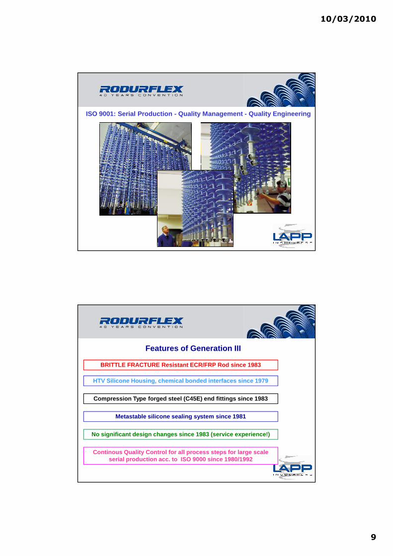
Features of Generation III
BRITTLE FRACTURE Resistant ECR/FRP Rod since 1983
HTV Silicone Housing, chemical bonded interfaces si nce 1979
Compression Type forged steel (C45E) end fittings s ince 1983
No significant design changes since 1983 (service e xperience!)
Continous Quality Control for all process steps for large scale serial production acc. to ISO 9000 since 1980/1992
Metastable silicone sealing system since 1981

10/03/2010
10
• pollution layer water repellent
• low leakage currents
• low risk of flashover
• low line losses
• no cleaning required
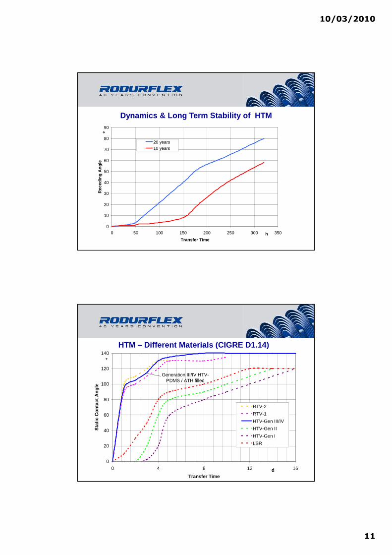
Hydrophobicity Transfer Mechanism (HTM), CIGRE D1.1 4
Prof. Kindersberger (Prof. Kindersberger (19891989))
Prof. Kindersberger (Prof. Kindersberger (19891989))
Hydrophobicity Transfer Mechanism (HTM), CIGRE D1.1 4
Time [days]
s = 0.15
0.30
0.45
0.60
0.75
0.90
Wet
ting
angl
eϑϑ ϑϑ
[deg
]
10/03/2010
11
0
10
20
30
40
50
60
70
80
90
0 50 100 150 200 250 300 350
Transfer Time
Rec
edin
g A
ngle
20 years10 years
°
h
Dynamics & Long Term Stability of HTM
0
20
40
60
80
100
120
140
0 4 8 12 16
Transfer Time
Sta
tic C
onta
ct A
ngle
RTV-2
RTV-1
HTV-Gen III/IV
HTV-Gen II
HTV-Gen I
LSR
Generation III/IV HTV-PDMS / ATH filled
°
d
HTM – Different Materials (CIGRE D1.14)

10/03/2010
12
Pollution Performance - Comparison
Required geometrical Creepage distances to obtain the same electrical performance under pol lution
(KIWIT 1970: „Practical Experience with Outdoor Insu lation)
Silicone Rubber Composite Porcelain Longrod Glass/Porcelain Disk
75% 100% 120%
reference-45%
CONCLUSION: To operate under same pollution conditions, a silic one rubber composite insulator
only requires 40..45% of the CD required for Glass/ Porcelain Disks. A silicone rubber composite is
Therefore more economical or can withstand a level of 2 pollution classes higher than glass.
HTM impact on LCC and Service Costs
0
50
100
150
200
250[$/year]
132 kV line 275 kV line
Silicone insulatorcoated ceramic discceramic disc with washing
Calculated by M/s Powerlink, Australia

10/03/2010
13
Pin CorrosionGlass/Porcelain Disks: not hydrophobic surface ⇒⇒⇒⇒ high Leakage currents ⇒⇒⇒⇒ DC component in Leakage current ⇒⇒⇒⇒
galvanic cell ⇒⇒⇒⇒ PIN CORROSION
Silicone rubber composite with HTM & hydrophobic surface: not hydrophobic surface ⇒⇒⇒⇒ very low Leakage currents ⇒⇒⇒⇒ no DC component in Leakage current ⇒⇒⇒⇒
no galvanic cell ⇒⇒⇒⇒ NO PROBLEMS
Maintenance costs, lower lifetime, worse LCA
Life expectancy: 17…30a
Composite insulators offer low weight
=> low transport and installation costs
Composite Insulators SystemComposite Insulators System RodurflexRodurflex ®®
Introduction
10/03/2010
14
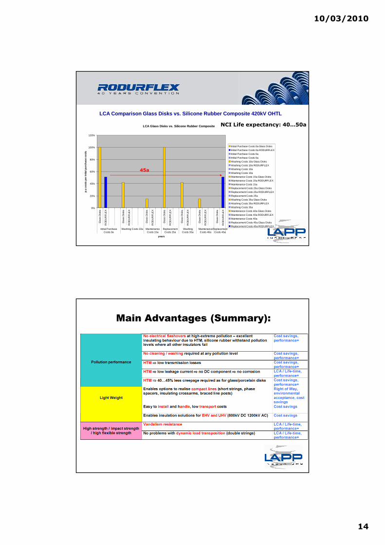
LCA Comparison Glass Disks vs. Silicone Rubber Comp osite 420kV OHTL
LCA Glass Disks vs. Silicone Rubber Composite
0%
20%
40%
60%
80%
100%
120%
Gla
ss D
isks
RO
DU
RF
LEX
Gla
ss D
isks
RO
DU
RF
LEX
Gla
ss D
isks
RO
DU
RF
LEX
Gla
ss D
isks
RO
DU
RF
LEX
Gla
ss D
isks
RO
DU
RF
LEX
Gla
ss D
isks
RO
DU
RF
LEX
Gla
ss D
isks
RO
DU
RF
LEX
Initial PurchaseCosts 0a
Washing Costs 10a MaintenanceCosts 15a
ReplacementCosts 25a
WashingCosts 35a
MaintenanceCosts 40a
ReplacementCosts 45a
years
p.u
cost
s pe
r int
ial p
urch
ase
cost
s
Initial Purchase Costs 0a Glass Disks
Initial Purchase Costs 0a RODURFLEX
Initial Purchase Costs 0a
Initial Purchase Costs 0a
Washing Costs 10a Glass Disks
Washing Costs 10a RODURFLEX
Washing Costs 10a
Washing Costs 10a
Maintenance Costs 15a Glass Disks
Maintenance Costs 15a RODURFLEX
Maintenance Costs 15a
Replacement Costs 25a Glass Disks
Replacement Costs 25a RODURFLEX
Replacement Costs 25a
Washing Costs 35a Glass Disks
Washing Costs 35a RODURFLEX
Washing Costs 35a
Maintenance Costs 40a Glass Disks
Maintenance Costs 40a RODURFLEX
Maintenance Costs 40a
Replacement Costs 45a Glass Disks
Replacement Costs 45a RODURFLEX
45a
NCI Life expectancy: 40…50a
Main Advantages (Summary):

10/03/2010
15
Methods Used in China to Assess Composite Insulators after Years in Service
LIANG Xidong1, WANG Jiafu1, SHEN Qinghe2, ZHANG Yibo1, LI Yan31. State Key Lab of Power System, Dept. of Electrical Engineering, Tsinghua University, Beijing 100084, China;
2. Shandong Electric Power Research Institute, Ji’nan 250002, China; 3. Technology Research Center, China Southern Power Grid Co., LTD., Guangzhou 510623, China.
Abstract: Maintenance on silicone rubber insulators is quite different from that on porcelain and glass insulators. Sampling result based maintenance is a widely used method for silicone rubber composite insulator maintenance in China. The principle, test items, measures and other details were introduced in the present paper.
Key Words: Composite insulator; Maintenance; Sampling result based maintenance; Maintenance-free period
The first maintenance-free period
The second maintenance-free
period
The third maintenance-free
period…
5~8 years based on manufacture
quality and operation experience
5~8 years* based on sampling
results
4~6 years* based on sampling
results…
„Sampling Result Based Maintenance“
Advantages of RODURFLEX® Composite Insulators• Enables new OHTL Insulation Design (Crossarms,Cross ropes etc.)
• Superior Pollution Performance (Hydrophobicity Tran sfer Mechanism)
• Extreme UV, Weather and Environmental Resistant HTV Silicone Housing
• Enables Extreme Creepage Designs (Patented Underrib Sheds)
• Earthquake Resistant
• Brittle Fracture Resistant (ECR Glass Epoxy FRP Cor e)
• Fail-safe meta stable sealing system
• Extreme strength classes SML up to 2000 kN possible for single unit
• Vandalism Proof
• Able to withstand Extreme Dynamic and Impact loads
• Light Weight: Easy Transport, Handling, Installatio n
• Light Weight: offers EHV OHTL designs
• Short Lead-Time
• Flexible in Design
• Reduced Life-Cycle Costs
• Proven since more than 40 years

10/03/2010
16
Generation III: Applications Worldwide
up to Um=1100kV
4. Innovations in Design & Development
5. Generation IV (Video)

10/03/2010
17
Prof. Kindersberger (Prof. Kindersberger (19891989))Time [days]
s = 0.15
0.30
0.45
0.60
0.75
0.90
Wet
ting
angl
eϑϑ ϑϑ
[deg
]Hydrophobicity Transfer Mechanism (HTM), CIGRE D1.1 4
Resistance against Tracking & Erosion - ATH Content
0,01
0,1
1
10
48% 55% 60%ATH Content
Mas
s Lo
ss i
n %
3,5 kV4,5 kV
Test Duration: 6h
10/03/2010
18
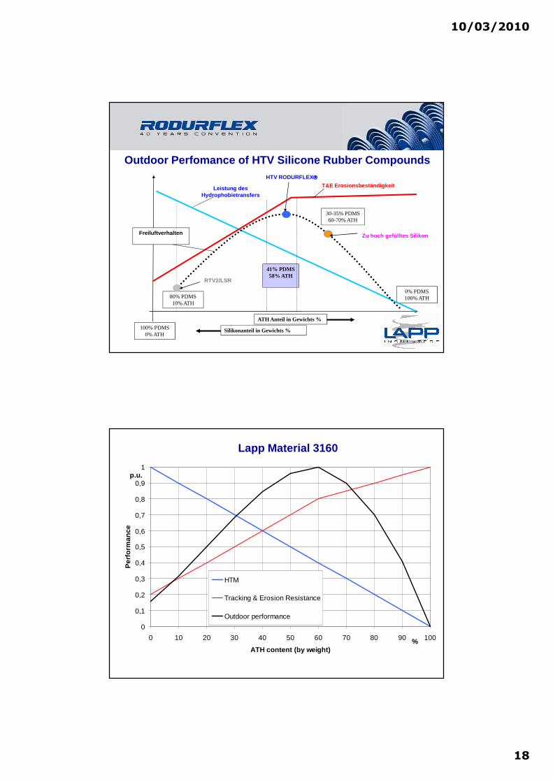
Outdoor Perfomance of HTV Silicone Rubber Compounds
Freiluftverhalten
ATH Anteil in Gewichts %
Silikonanteil in Gewichts %100% PDMS0% ATH
0% PDMS100% ATH
41% PDMS58% ATH
Leistung des Hydrophobietransfers
T&E Erosionsbeständigkeit
80% PDMS10% ATH
30-35% PDMS60-70% ATH
HTV RODURFLEX
Zu hoch gefülltes Silikon
RTV2/LSR
0
0,1
0,2
0,3
0,4
0,5
0,6
0,7
0,8
0,9
1
0 10 20 30 40 50 60 70 80 90 100
ATH content (by weight)
Per
form
ance
HTM
Tracking & Erosion Resistance
Outdoor performance
p.u.
%
Lapp Material 3160
10/03/2010
19
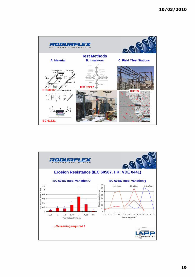
Test Methods
Dip period
Energizedperiod
Suspension type insulator
Grounded insulatorsupport wheel
Rotation in 90 steps0
Coolingperiod Drip period
Salt water
HV
A. Material B. Insulators C. Field / Test Stations
IEC 60587
IEC 61621
IEC 62217KIPTS
0
0,2
0,4
0,6
0,8
1
1,2
2,5 3 3,5 3,75 4 4,25 4,5
Test Voltage Ueff in kV
Max
. Ero
sion
dep
th in
mm
0
0,1
0,2
0,3
0,4
0,5
0,6
0,7
0,8
2,5 2,75 3 3,25 3,5 3,75 4 4,25 4,5 4,75 5
Test voltage in kV
Ero
sion
dep
th in
mm
4,0 mS/cm 2,5 mS/cm 1,5 mS/cm
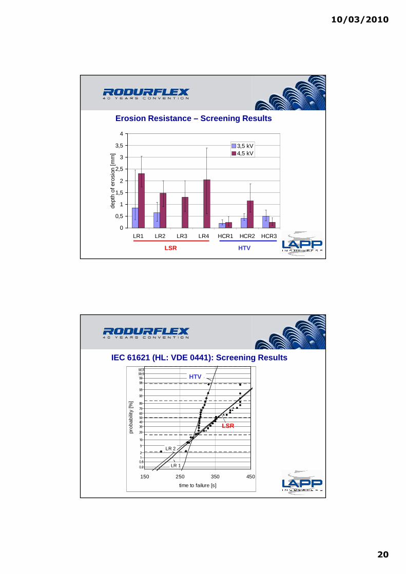
Erosion Resistance (IEC 60587, HK: VDE 0441)
IEC 60587 mod, Variation U IEC 60587 mod, Variation χχχχ
⇒⇒⇒⇒ Screening required !
10/03/2010
20
0
0,5
1
1,5
2
2,5
3
3,5
4
LR1 LR2 LR3 LR4 HCR1 HCR2 HCR3
dept
h of
ero
sion
[mm
]
3,5 kV4,5 kV
Erosion Resistance – Screening Results
HTVLSR
99,8
99,5
99
98
95
90
80
70
60
50
40
30
20
10
5
2
1
0,5
0,2
150 250 350 450
time to failure [s]
pro
bab
ility
[%]
HCR-1
LR 1
LR 2
IEC 61621 (HL: VDE 0441): Screening Results
HTV
LSR
10/03/2010
21
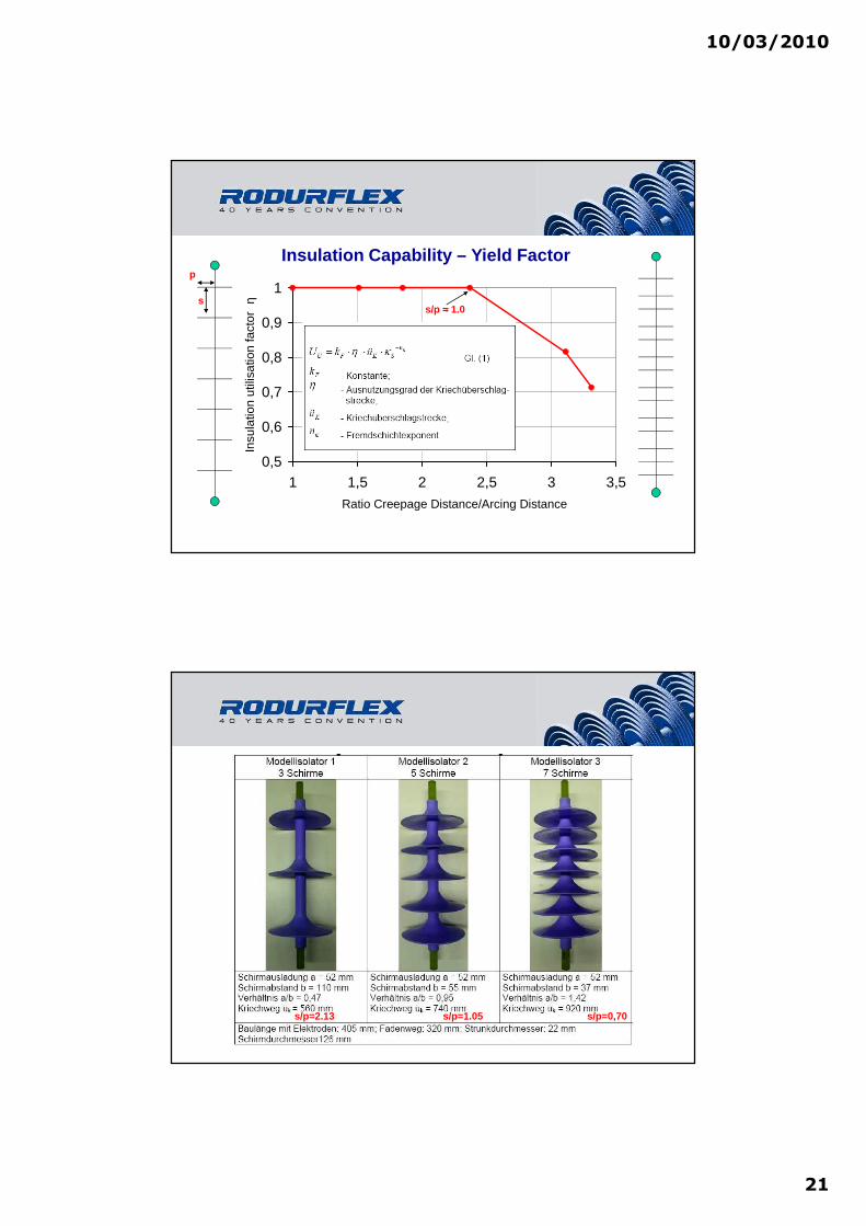
0,5
0,6
0,7
0,8
0,9
1
1 1,5 2 2,5 3 3,5
Ratio Creepage Distance/Arcing Distance
Insu
latio
n ut
ilisa
tion
fact
or
η Insulation Capability – Yield Factor
s/p ≈≈≈≈ 1.0s
p
s/p=2.13 s/p=1.05 s/p=0,70

10/03/2010
22
Shed / Housing Design (Profiles)Standard Flat Underrib
Shallow Underribs
insulator type 1 insulator type 2 insulator type 3standard housing profile flat profile underrib profile
s/p** = 0,58 s/p** = 0,60 s/p** = 0,74CD’ = 20,6 mm/kV CD’ = 20 mm/kV CD’ = 18,6 mm/kV
(CD)
Salt Fog Test IEC 62217: 1000h Test

10/03/2010
23
Start of Erosion
Leakage Current
Local Arc Stability
Material Damage
Damage limit
Creepage Distance
10/03/2010
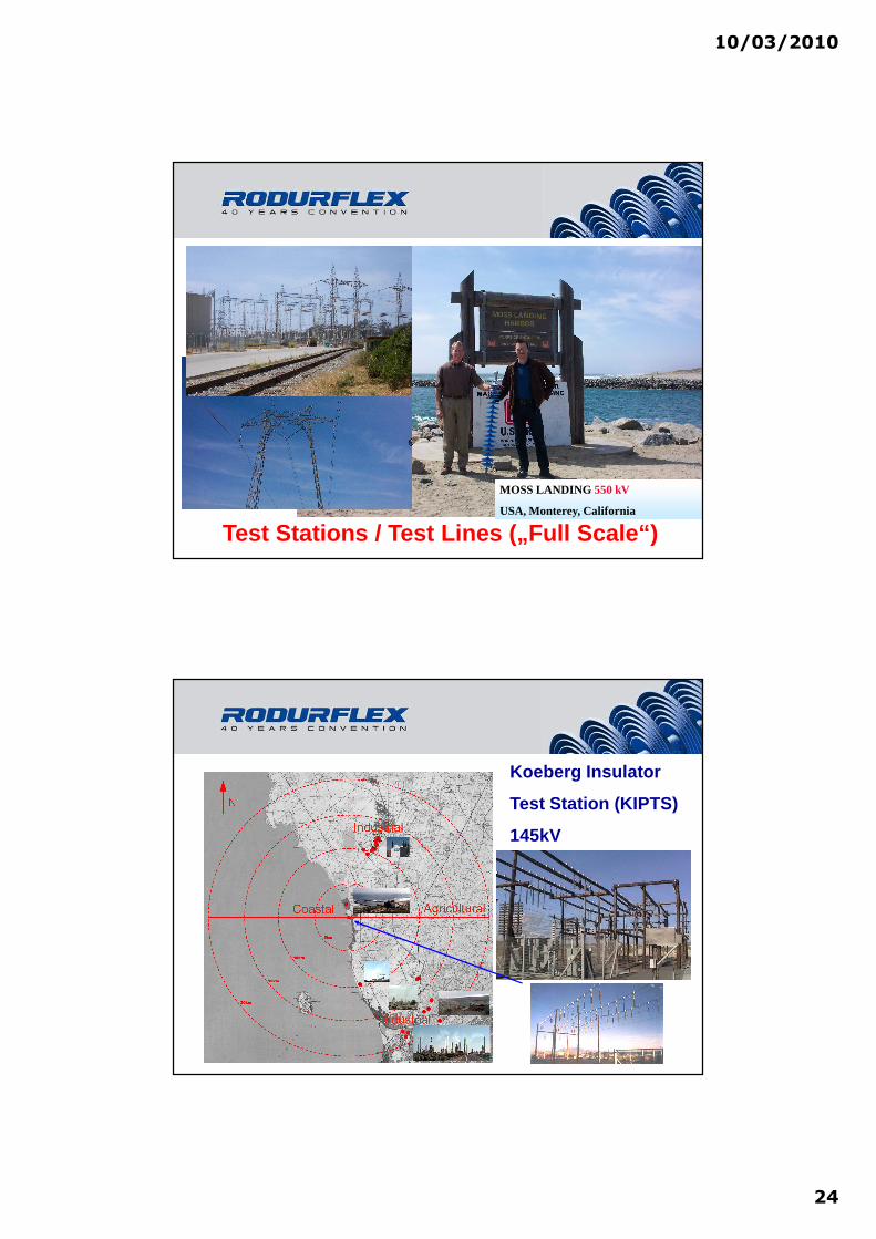
24
Test Stations / Test Lines („Full Scale“)
MOSS LANDING 550 kV
USA, Monterey, California
Koeberg Insulator
Test Station (KIPTS)
145kV

10/03/2010
25
Design Study (KIPTS)
Approach Shed Design h1 [mm] cd [mm] s/p* s/p**
Standard CS120SB (22/23(160/126)1475 1475+/-15 3625 1.50.75
Underrib CS120SB 22/16(170/130)1485 1485+/-15 3655 2.0 1.0
145kVVarying s/p
CD=25mm/kV=consth1=const Flat CS120SB 22/23(155/120)1485 1485+/-15 3630 1.6 0.8
Standard CS120SB 22/31(160/126)1485 1485+/-15 4495 1.160.58
Underrib CS120SB 22/22(170/130)1480 1480+-20 4550 1.48 0.74
145kVVarying s/p
CD=31mm/kV=consth1=const Flat CS120SB 22/31(155/120)1485 1485+-15 4495 1.2 0.6
Standard CS120SB 22/21(160/126)1700 1700+-20 3640 2.0 1.0
Underrib CS120SB 22/16(170/130)1485 1485+-15 3655 2.0 1.0
145kVs/p=1.0**
CD=25mm/kVh1= as it results Flat CS120SB 22/21(155/120)1700 1700+-20 3640 2.0 1.0
Standard CS120SB 22/26(160/126)2060 2060+-20 4495 2.0 1.0
Underrib CS120SB 22/20(170/130)1730 1730+-20 4500 2.0 1.0
145kVs/p=1.0**
CD=31mm/kVh1= as it results Flat CS120SB 22/26(155/120)2060 2060+-20 4495 2.0 1.0
* s/p: in acc.with IEC 60815 for alternating sheds h1: connection length (IEC 60815)** s/p: if calculated between large and small shed cd: creepage distance of housing (IEC 60815)s: shed spacing acc. to IEC 60815 p: shed projection (IEC 60815)
Standard Flat Underrib
Shallow Underribs
Design Study (KIPTS)
10/03/2010
26
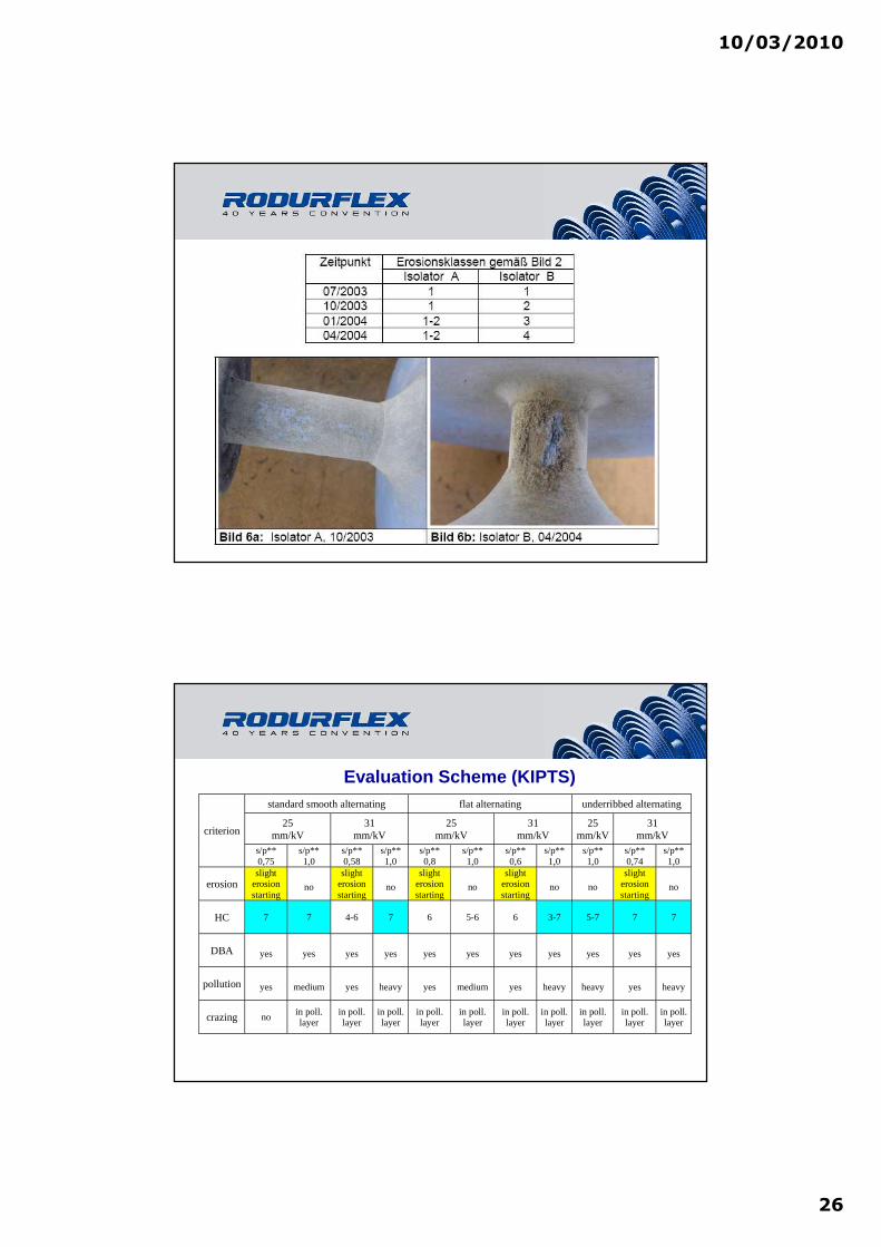
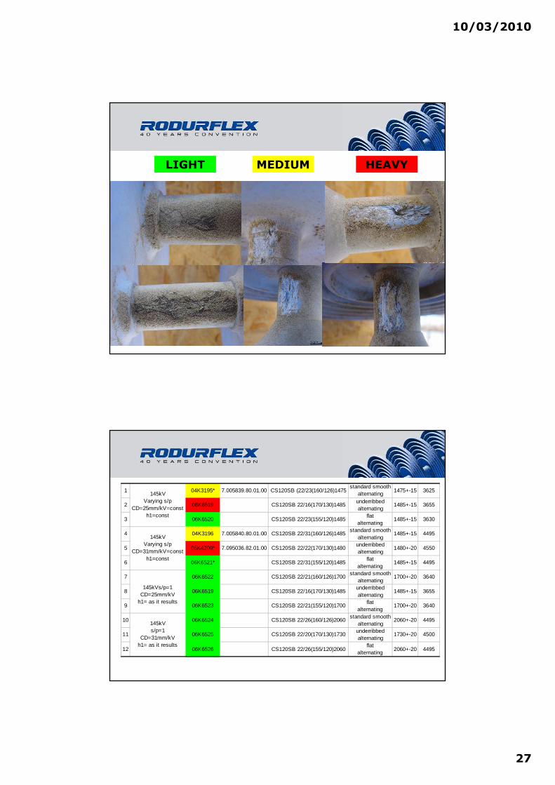
Bilder KIPTS 2007/2008
standard smooth alternating flat alternating underribbed alternating
25mm/kV
31mm/kV
25mm/kV
31mm/kV
25mm/kV
31mm/kVcriterion
s/p**0,75
s/p**1,0
s/p**0,58
s/p**1,0
s/p**0,8
s/p**1,0
s/p**0,6
s/p**1,0
s/p**1,0
s/p**0,74
s/p**1,0
erosionslight
erosionstarting
no
slighterosionstarting
no
slighterosionstarting
no
slighterosionstarting
no no
slighterosionstarting
no
HC 7 7 4-6 7 6 5-6 6 3-7 5-7 7 7
DBA yes yes yes yes yes yes yes yes yes yes yes
pollution yes medium yes heavy yes medium yes heavy heavy yes heavy
crazing noin poll.layer
in poll.layer
in poll.layer
in poll.layer
in poll.layer
in poll.layer
in poll.layer
in poll.layer
in poll.layer
in poll.layer
Evaluation Scheme (KIPTS)
10/03/2010
27
LIGHT MEDIUM HEAVY
1 04K3195* 7.005839.80.01.00 CS120SB (22/23(160/126)1475standard smooth
alternating1475+-15 3625
2 06K6519 CS120SB 22/16(170/130)1485underribbedalternating
1485+-15 3655
3 06K6520 CS120SB 22/23(155/120)1485flat
alternating1485+-15 3630
4 04K3196 7.005840.80.01.00 CS120SB 22/31(160/126)1485standard smooth
alternating1485+-15 4495
5 05K4209* 7.095036.82.01.00 CS120SB 22/22(170/130)1480underribbedalternating
1480+-20 4550
6 06K6521* CS120SB 22/31(155/120)1485flat
alternating1485+-15 4495
7 06K6522 CS120SB 22/21(160/126)1700standard smooth
alternating1700+-20 3640
8 06K6519 CS120SB 22/16(170/130)1485underribbedalternating
1485+-15 3655
9 06K6523 CS120SB 22/21(155/120)1700flat
alternating1700+-20 3640
10 06K6524 CS120SB 22/26(160/126)2060standard smooth
alternating2060+-20 4495
11 06K6525 CS120SB 22/20(170/130)1730underribbedalternating
1730+-20 4500
12 06K6526 CS120SB 22/26(155/120)2060flat
alternating2060+-20 4495
145kVs/p=1
CD=31mm/kVh1= as it results
145kVVarying s/p
CD=25mm/kV=consth1=const
145kVVarying s/p
CD=31mm/kV=consth1=const
145kVs/p=1CD=25mm/kV
h1= as it results

10/03/2010
28
Shed Profile: Why Underrib Sheds for Extreme Pollut ion?
• shallow UR offer high CD
• UR act as creepage extender
• s/p = 1.0 can be met with URs
• UR offer protected CD
• s/p = 1.0 avoids T&E
• efficient insulation at s/p = 1.0
• excellent performance history
RODURFLEX®: High Pollution Applications
• China (525, 750 kV)
• Arabic Peninsula (420 kV*) UAE, Qatar, Saudi Arabia, Oman, Jemen
• REE Spain (420 kV*)
• USA California (525 kV*)
• USA Florida (525 kV*)
• South Africa (420, 765 kV*)
• India (420, 765 kV)
• Australia (525 kV*)
• North Africa (420 kV*)
• Chile, Peru (245 kV*)
• Iran (420 kV*)
* up to
10/03/2010
29
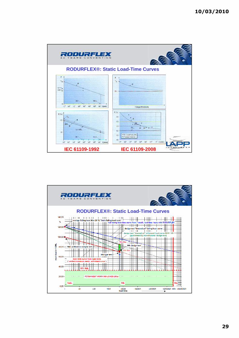
RODURFLEX®: Static Load-Time Curves
IEC 61109-1992 IEC 61109-2008
RODURFLEX®: Static Load-Time Curves

10/03/2010
30
10/03/2010
31
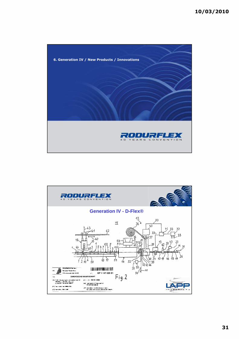
6. Generation IV / New Products / Innovations
Generation IV - D-Flex®
10/03/2010
32
Generation IV - D-Flex®
⇒⇒⇒⇒ VIDEO D-Flex®
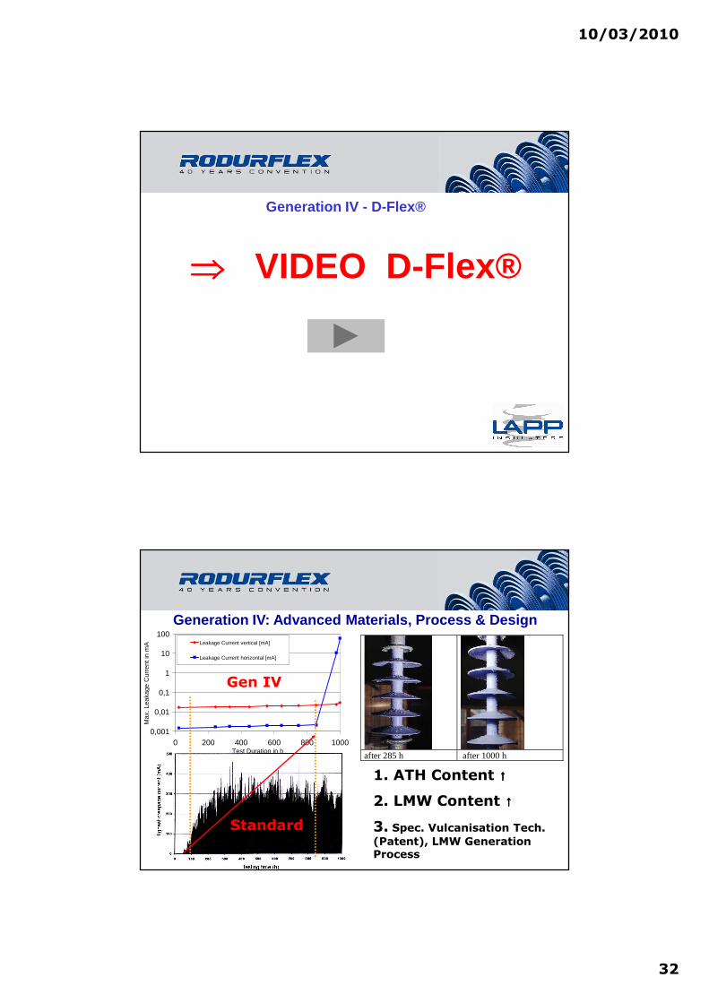
Generation IV: Advanced Materials, Process & Design
after 285 h after 1000 h
0,001
0,01
0,1
1
10
100
0 200 400 600 800 1000Test Duration in h
Max
. Lea
kage
Cur
rent
in m
A Leakage Current vertical [mA]
Leakage Current horizontal [mA]
1. ATH Content ↑↑↑↑
2. LMW Content ↑↑↑↑
3. Spec. Vulcanisation Tech.
(Patent), LMW Generation Process
Standard
Gen IV
10/03/2010
33
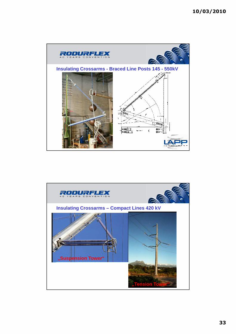
Insulating Crossarms - Braced Line Posts 145 - 550kV
Insulating Crossarms – Compact Lines 420 kV
„Suspension Tower“
„Tension Tower“

10/03/2010
34
Compact Lines –Invisible Tower 420 kV
Composite Station Posts 36 - 550kV
Core ∅∅∅∅[mm] [inch]
Pollution Classes *
[SCD, IEC 60815]
Maximum Cantilever Moment **
[kN m]
Um***
[kV]
36.8 1.45 12-31 mm/kV 10 3645.0 1.75 12-31 mm/kV 15 72.563.5 2.5 12-31 mm/kV 20 17076.2 3.0 12-31 mm/kV 30 24588.9 3.5 12-31 mm/kV 40 362101.6 4.0 12-31 mm/kV 50 550
10/03/2010
35
7. Impact of New Standards
The Impact of Standards
No Standard
⇒⇒⇒⇒ No Business

10/03/2010
36
IEC Insulator Standard System
IEC 60815Auslegung Schirmprofil/Verschmutzung
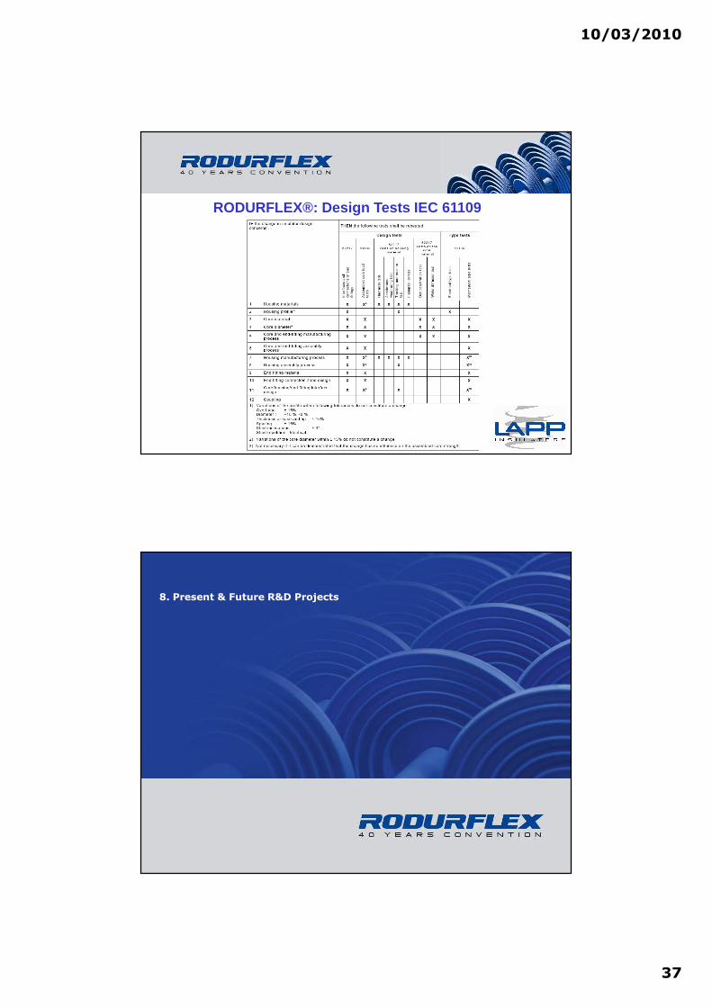
RODURFLEX®: Design Tests IEC 61109
10/03/2010
37
RODURFLEX®: Design Tests IEC 61109
8. Present & Future R&D Projects

10/03/2010
38
R&D Partners
Prof. Kindersberger
Prof. Kurrat
Prof. Bärsch
Prof. Hinrichsen
Prof. Clemens
Prof. Grossmann
R&D: New Design Tools (FEM)

10/03/2010
39
R&D : FEM/BEM Tools
R&D on Field Calculations (HSU Hamburg)

10/03/2010
40
R&D at TU Braunschweig1. Field Related Problems (“ Water Drop Corona “)
2. “Interfacial Phenomena in Composite Materials“
0
0,005
0,01
0,015
0,02
0,025
0,03
0,035
0,04
0,045
0,05
0 2 4 6 8 10 12 14
Zeit / Tage
Tan
Del
ta
Bild 6Mit der Impulsladung gewichtete Häufichkeits-Randverteilung a)Tag 0b)Tag 14
0
20
40
60
80
100
120
140
0,0 45,0 90,0 135,0 180,0 225,0 270,0 315,0 360,0
Phasenwinkel / °
hnq(Phasenwinkel) / q*n
Mittelwert 1.Maximumsbereich : 48,51 (H*q), Max. bei 73,5
Mittelwert 2.Maximumsbereich : 46,53(H*q), Max. bei 261,5°
0
20
40
60
80
100
120
140
0,0 45,0 90,0 135,0 180,0 225,0 270,0 315,0 360,0
Phasenwinkel / °
hnq(Phasenwinkel) / q*n
Mittelwert 1.Maximumsbereich: 42,46 (H*q) , Max. bei 88°
Mittelwert 2. Maximumsbereich : 55,01(H*q) , Max. bei 264°
a)
b)
Dynamic Drop Test
Present Work @ CIGRE D1.14 / .27

10/03/2010
41
R&D: New Design Tools (STRI Insulator Selection Too l IST®)
HVAC
HVDC
AC/DC Solid Layer
AC / KIPTS

10/03/2010
42
Pollution Severity: 2% ESDD Level (mg/cm²)0,001 0,01 0,1 1
Insu
latio
n Le
ngth
(m
)1,8
1,7
1,6
1,5
1,4
1,3
1,2
1,1
1,0
0,9
0,8
0,7
0,6
0,5
Spe
cific
Cre
epag
e D
ista
nce
(mm
/kV
syst
em)
48
46
44
42
40
38
36
34
32
30
28
26
24
22
20
18
16
14
AC KIPTS Natural Pollution Performance 123kV
Glass Antifog 33mm/kV
Pollution Severity: 2% ESDD Level (mg/cm²)0,001 0,01 0,1 1
Insu
latio
n Le
ngth
(m
)
1,1
1,0
0,9
0,8
0,7
0,6
0,5
Spe
cific
Cre
epag
e D
ista
nce
(mm
/kV
syst
em)
30
28
26
24
22
20
18
16
14
12
Rodurflex ® 31mm/kV
AC KIPTS Natural Pollution Performance 245kV
Pollution Severity: 2% ESDD Level (mg/cm²)0,001 0,01 0,1 1
Insu
latio
n Le
ngth
(m
)
3,6
3,4
3,2
3,0
2,8
2,6
2,4
2,2
2,0
1,8
1,6
1,4
1,2
1,0
Spe
cific
Cre
epag
e D
ista
nce
(mm
/kV
syst
em)
48
46
44
42
40
38
36
34
32
30
28
26
24
22
20
18
16
14
Pollution Severity: 2% ESDD Level (mg/cm²)0,001 0,01 0,1 1
Insu
latio
n Le
ngth
(m
)
2,2
2,1
2,0
1,9
1,8
1,7
1,6
1,5
1,4
1,3
1,2
1,1
1,0
0,9
Spe
cific
Cre
epag
e D
ista
nce
(mm
/kV
syst
em)
30
28
26
24
22
20
18
16
14
12
Glass Antifog 29mm/kV
Rodurflex ® 31mm/kV

10/03/2010
43
Pollution Severity: 2% ESDD Level (mg/cm²)0,001 0,01 0,1 1
Insu
latio
n Le
ngth
(m
)6,0
5,5
5,0
4,5
4,0
3,5
3,0
2,5
2,0 Spe
cific
Cre
epag
e D
ista
nce
(mm
/kV
syst
em)
48
46
44
42
40
38
36
34
32
30
28
26
24
22
20
18
16
14
Pollution Severity: 2% ESDD Level (mg/cm²)0,001 0,01 0,1 1
Insu
latio
n Le
ngth
(m
)
3,8
3,6
3,4
3,2
3,0
2,8
2,6
2,4
2,2
2,0
1,8
1,6 Spe
cific
Cre
epag
e D
ista
nce
(mm
/kV
syst
em)
30
28
26
24
22
20
18
16
14
12
AC KIPTS Natural Pollution Performance 420kV
Glass Antifog 25mm/kV
Rodurflex® 25mm/kV
Pollution Severity: 2% ESDD Level (mg/cm²)0,001 0,01 0,1 1
Insu
latio
n Le
ngth
(m
)
8,0
7,5
7,0
6,5
6,0
5,5
5,0
4,5
4,0
3,5
3,0
2,5 Spe
cific
Cre
epag
e D
ista
nce
(mm
/kV
syst
em)
48
46
44
42
40
38
36
34
32
30
28
26
24
22
20
18
16
14
AC KIPTS Natural Pollution Performance 550kV
Pollution Severity: 2% ESDD Level (mg/cm²)0,001 0,01 0,1 1
Insu
latio
n Le
ngth
(m
)
5,0
4,8
4,6
4,4
4,2
4,0
3,8
3,6
3,4
3,2
3,0
2,8
2,6
2,4
2,2
2,0
Spe
cific
Cre
epag
e D
ista
nce
(mm
/kV
syst
em)
30
28
26
24
22
20
18
16
14
12
Rodurflex® 28mm/kV
Glass Antifog 26mm/kV
10/03/2010
44
Pollution Severity: 2% ESDD Level (mg/cm²)0,001 0,01 0,1 1
Insu
latio
n Le
ngth
(m
)
12,0
11,5
11,0
10,5
10,0
9,5
9,0
8,5
8,0
7,5
7,0
6,5
6,0
5,5
5,0
4,5
4,0
3,5
Spe
cific
Cre
epag
e D
ista
nce
(mm
/kV
syst
em)
48
46
44
42
40
38
36
34
32
30
28
26
24
22
20
18
16
14
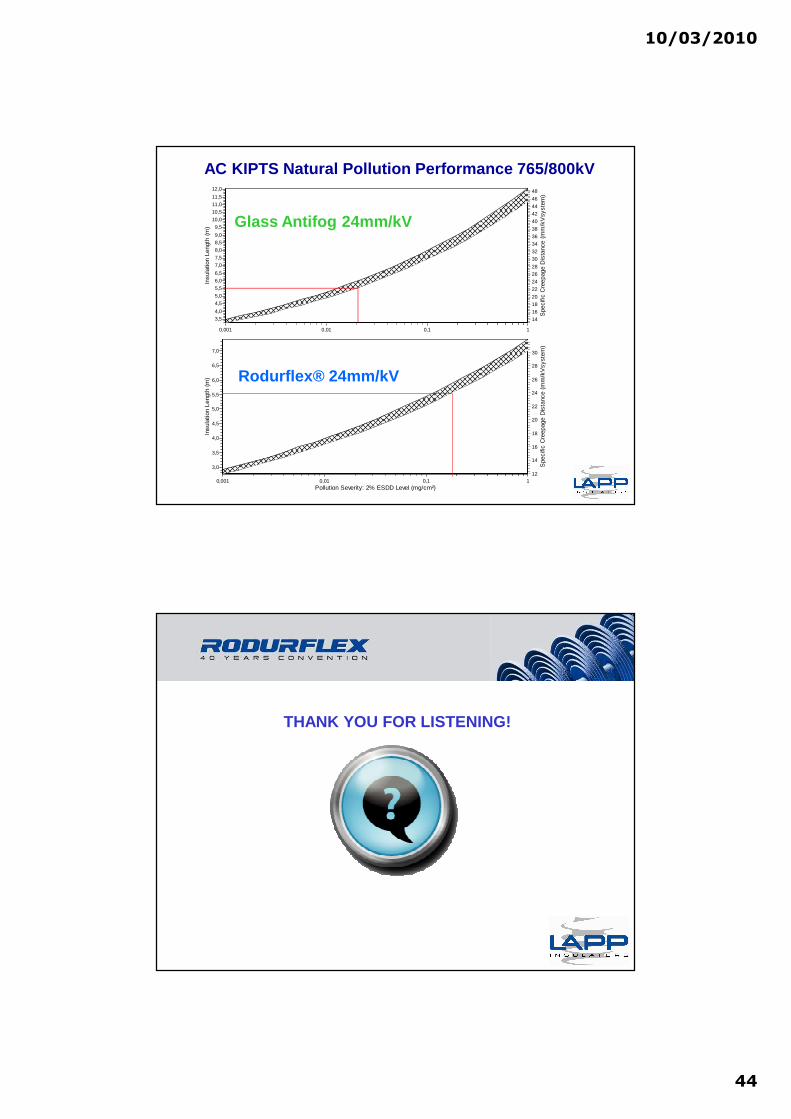
AC KIPTS Natural Pollution Performance 765/800kV
Pollution Severity: 2% ESDD Level (mg/cm²)0,001 0,01 0,1 1
Insu
latio
n Le
ngth
(m
)
7,0
6,5
6,0
5,5
5,0
4,5
4,0
3,5
3,0 Spe
cific
Cre
epag
e D
ista
nce
(mm
/kV
syst
em)
30
28
26
24
22
20
18
16
14
12
Glass Antifog 24mm/kV
Rodurflex® 24mm/kV
THANK YOU FOR LISTENING!