ComponentsTo determine the fineness of cement by dry sieving as per IS: 4031 (Part -1) 1996....
62
Transcript of ComponentsTo determine the fineness of cement by dry sieving as per IS: 4031 (Part -1) 1996....


Components
Walls
Roof
Foundation

Material Test in Laboratory
WaterAbsorption
Test
EfflorescenceTest
BrickTest
Compressive
Strength
Test
Size & ShapeTest
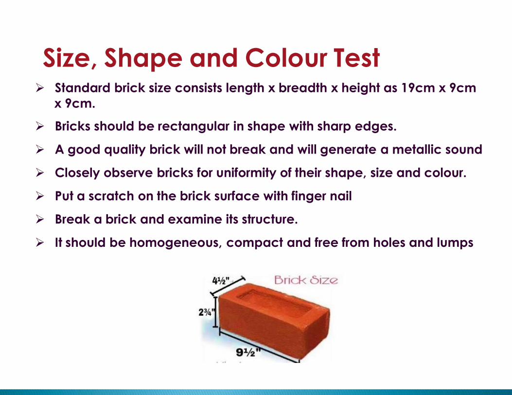
Size, Shape and Colour Test Standard brick size consists length x breadth x height as 19cm x 9cm
x 9cm.
Bricks should be rectangular in shape with sharp edges.
A good quality brick will not break and will generate a metallic sound
Closely observe bricks for uniformity of their shape, size and colour.
Put a scratch on the brick surface with finger nail
Break a brick and examine its structure.
It should be homogeneous, compact and free from holes and lumps

Apparatus: Drying Oven and Immersion Tank
Water Absorption TestTo determine Water absorption as per IS: 3495 (Part-II) – 1976.
Procedure Select five bricks at random.
Dry the specimen in a drying oven at a temperature of 110’C to 115’C for
24hrs.
Remove the bricks from the oven and obtain it’s weight W 1 (kg)
Immerse the five bricks completely in water at 27’+/-2’C for 24hrs.
Remove the specimen and weigh the specimen within three minutes after
it’s removal from water. Let its weight be W 2 (kg).
Take the average value of water absorption
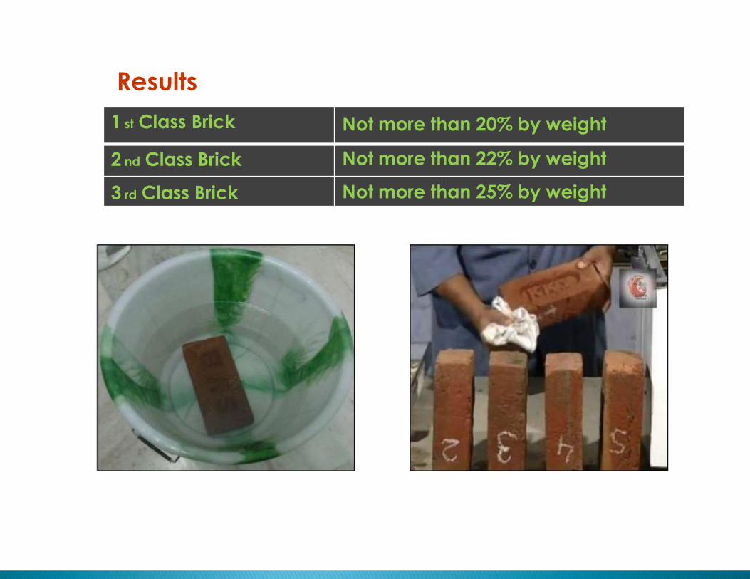
Not more than 20% by weight
Not more than 22% by weight
Not more than 25% by weight
Results
1 st Class Brick
2 nd Class Brick
3 rd Class Brick
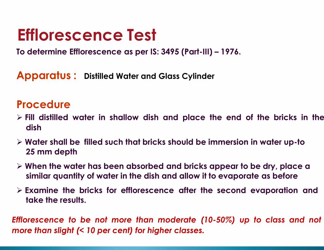
Efflorescence TestTo determine Efflorescence as per IS: 3495 (Part-III) – 1976.
Apparatus : Distilled Water and Glass Cylinder
Procedure Fill distilled water in shallow dish and place the end of the bricks in the
dish
Water shall be filled such that bricks should be immersion in water up-to
25 mm depth
When the water has been absorbed and bricks appear to be dry, place a
similar quantity of water in the dish and allow it to evaporate as before
Examine the bricks for efflorescence after the second evaporation and
take the results.
Efflorescence to be not more than moderate (10-50%) up to class and not
more than slight (< 10 per cent) for higher classes.

Nil
Slight
Moderate
Heavy
Serious
- No efflorescence
- 10% of area covered with deposits
-10to50%areacoveredwithdepositbutunaccompaniedby
- flakingofthesurface.
- Morethan50percentareacoveredwithdepositsbut
unaccompaniedbyflakingofthesurface.
Heavydepositsofsaltaccompaniedbyflakingofthesurface
Results
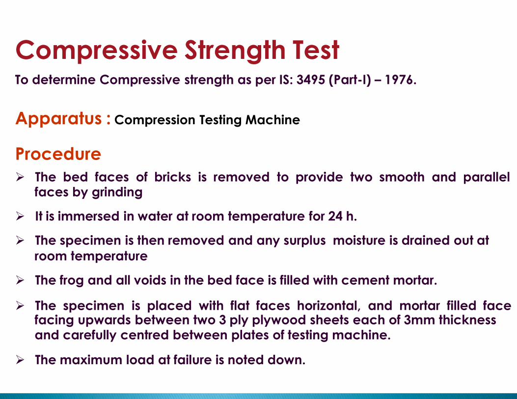
Compressive Strength TestTo determine Compressive strength as per IS: 3495 (Part-I) – 1976.
Apparatus : Compression Testing Machine
Procedure
The bed faces of bricks is removed to provide two smooth and parallelfaces by grinding
It is immersed in water at room temperature for 24 h.
The specimen is then removed and any surplus moisture is drained out at
room temperature
The frog and all voids in the bed face is filled with cement mortar.
The specimen is placed with flat faces horizontal, and mortar filled facefacing upwards between two 3 ply plywood sheets each of 3mm thicknessand carefully centred between plates of testing machine.
The maximum load at failure is noted down.


Material Test in Laboratory
Water
Absorptionof Sand
Sand
Test
Bulking ofSand
OrganicImpurities
of Sand

Specific Gravity and Water Absorption
To determine specific gravity of sand as per IS: 2386 (Part-III) – 1963.
Apparatus : Pycnometer and Balance
Procedure The sand sample be immersed in clean water for 24 hours and dried to
saturated and surface dry condition
One sample is placed in oven and dried to constant weight and weight isrecorded A
Pycnometer is filled about three-quarters full of water known the saturated
surface and dry sample B
The jar than filled with water and covered with a glass disc by sliding thedisk across the top of the jar
The jar is shaken to remove all remaining entrapped air
The disk is than replaced, making no air voids remains and surface is
dried The jar with disc in place and weight recorded as W
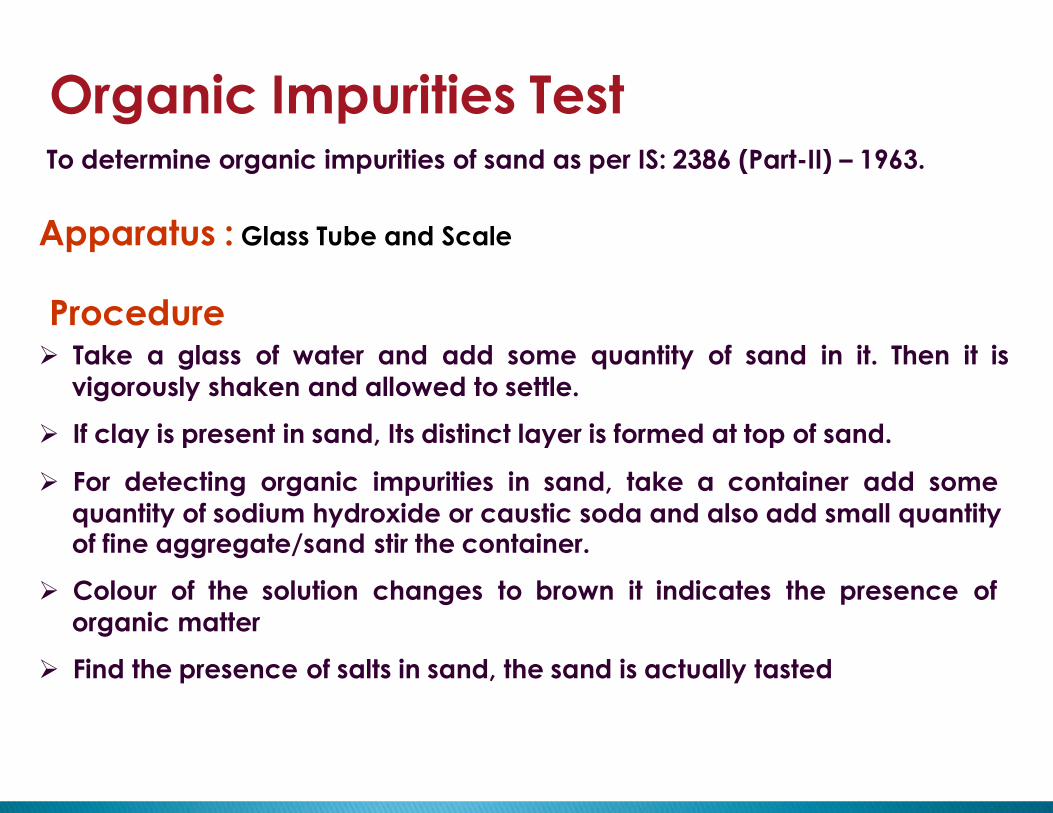
Organic Impurities TestTo determine organic impurities of sand as per IS: 2386 (Part-II) – 1963.
Apparatus : Glass Tube and Scale
Procedure Take a glass of water and add some quantity of sand in it. Then it is
vigorously shaken and allowed to settle.
If clay is present in sand, Its distinct layer is formed at top of sand.
For detecting organic impurities in sand, take a container add some
quantity of sodium hydroxide or caustic soda and also add small quantityof fine aggregate/sand stir the container.
Colour of the solution changes to brown it indicates the presence of
organic matter
Find the presence of salts in sand, the sand is actually tasted
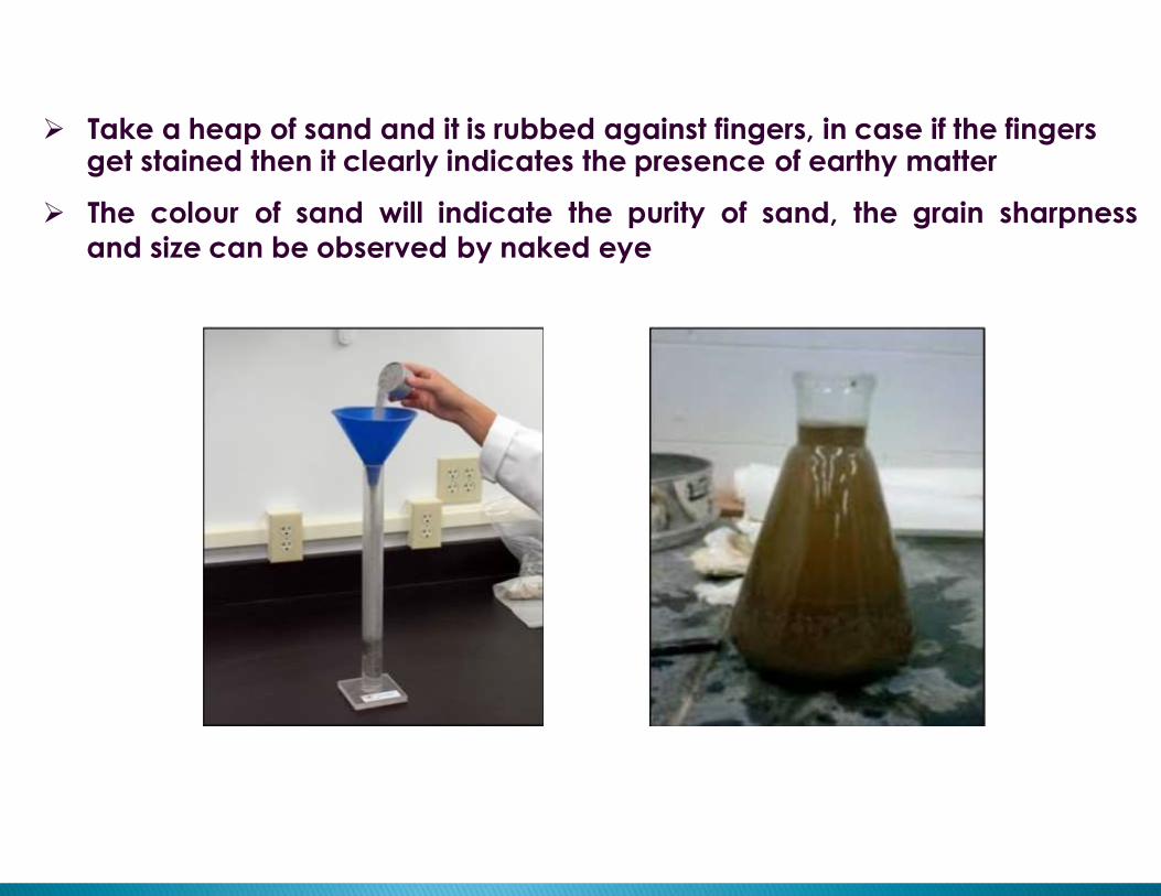
Take a heap of sand and it is rubbed against fingers, in case if the fingersget stained then it clearly indicates the presence of earthy matter
The colour of sand will indicate the purity of sand, the grain sharpness
and size can be observed by naked eye

23
Bulking of SandTo determine Bulking of sand as per IS: 2386 (Part-III) – 1963.
Procedure Take a simple container and add 2/3 part of sand in it.
Measure the exact height of sand using the scale and note it down. (H 1 )
Now fill the container upto 2/3 part with water. (Same height of Sand)
Now add the measured sand to the container and wait for some time tosettle down.
Now calculate the height of Sand in water. (H 2 )

Material Test in Laboratory
Fineness
Test
StandardConsistency
CementTest
Soundness
Test
CompressiveStrength Test
25
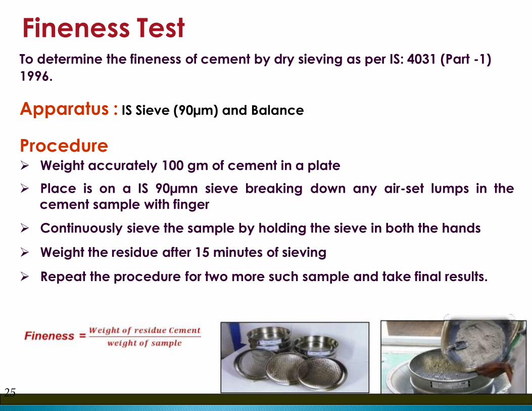
Fineness TestTo determine the fineness of cement by dry sieving as per IS: 4031 (Part -1)
1996.
Apparatus : IS Sieve (90µm) and Balance
Procedure Weight accurately 100 gm of cement in a plate
Place is on a IS 90µmn sieve breaking down any air-set lumps in the
cement sample with finger
Continuously sieve the sample by holding the sieve in both the hands
Weight the residue after 15 minutes of sieving
Repeat the procedure for two more such sample and take final results.

Standard Consistency and Setting TimeTo determine the standard consistency as per IS: 4031:(Part 1) 1996.
Apparatus : Vicat’s Apparatus, Plunger and Stop Watch
26
Procedure Take apparatus and place the rubber mould beneath the rod
Set the 10 mm. dia. plunger on the lower side of rod. Place the lower end
of plunger just above the surface of paste
Now release the rod and note down the penetration of plunger in the
paste
Normal consistence the penetration should be 10 mm according to ASTM
standard on room temperature
If it’s not so then the water and cement ratio will not
be standard

Final setting time = 90 + 1.2 (initial setting time)
Initial Setting Time Test Set the 1mm. diameter needle on the lower end of the rod.
Now release the rod for 30 seconds and note the time at
which the needle was released
After periodic time again release the rod for 30 seconds
note the penetration of the needle in paste.
Calculate the total time up to this step, which will be
the initial setting time of the cement.
Final Setting Time Test Set the 5 mm diameter needle on the lower end of the rod.
Now again repeat the above steps for noting the
final setting time of cement.
The final setting time will be noted when the needle if
released doesn’t sink visibly and leaves no impression onthe surface of the paste.
Then compare it with the ASTM standard time
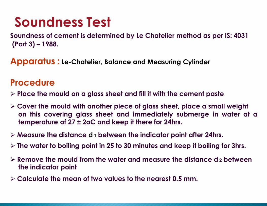
Soundness TestSoundness of cement is determined by Le Chatelier method as per IS: 4031
(Part 3) – 1988.
Apparatus : Le-Chatelier, Balance and Measuring Cylinder
Procedure Place the mould on a glass sheet and fill it with the cement paste
Cover the mould with another piece of glass sheet, place a small weight
on this covering glass sheet and immediately submerge in water at atemperature of 27 ± 2oC and keep it there for 24hrs.
Measure the distance d 1 between the indicator point after 24hrs.
The water to boiling point in 25 to 30 minutes and keep it boiling for 3hrs.
Remove the mould from the water and measure the distance d 2 betweenthe indicator point
Calculate the mean of two values to the nearest 0.5 mm.

Soundness of cement = d 1 - d 2
Le-Chatelier Apparatus

Compressive Strength Test

After 24hr. remove the specimen from the mould and keep them in watertill testing
The test cubes at 3days and 7days age in the compression testing
machine.
Compressive Strength = P / A

CrushingTest
SieveAnalysis
Test
Material Test in Laboratory
SpecificGravity
AggregatesTest
AbrasionTest
ImpactTest
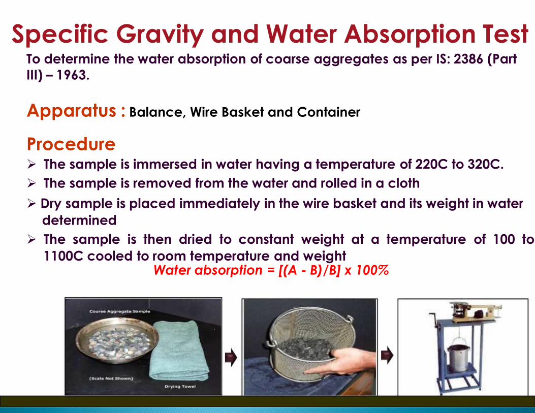
Specific Gravity and Water Absorption TestTo determine the water absorption of coarse aggregates as per IS: 2386 (Part
III) – 1963.
Apparatus : Balance, Wire Basket and Container
Procedure The sample is immersed in water having a temperature of 220C to 320C.
The sample is removed from the water and rolled in a cloth
Dry sample is placed immediately in the wire basket and its weight in water
determined
The sample is then dried to constant weight at a temperature of 100 to
1100C cooled to room temperature and weightWater absorption = [(A - B)/B] x 100%
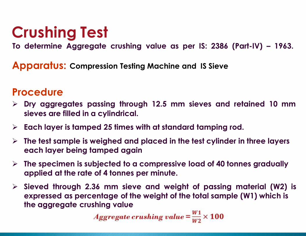
Crushing TestTo determine Aggregate crushing value as per IS: 2386 (Part-IV) – 1963.
Apparatus: Compression Testing Machine and IS Sieve
Procedure Dry aggregates passing through 12.5 mm sieves and retained 10 mm
sieves are filled in a cylindrical.
Each layer is tamped 25 times with at standard tamping rod.
The test sample is weighed and placed in the test cylinder in three layers
each layer being tamped again
The specimen is subjected to a compressive load of 40 tonnes gradually
applied at the rate of 4 tonnes per minute.
Sieved through 2.36 mm sieve and weight of passing material (W2) is
expressed as percentage of the weight of the total sample (W1) which isthe aggregate crushing value
35
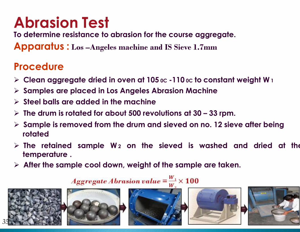
Abrasion TestTo determine resistance to abrasion for the course aggregate.
Apparatus : Los –Angeles machine and IS Sieve 1.7mm
Procedure
Clean aggregate dried in oven at 105 0C -110 0C to constant weight W 1
Samples are placed in Los Angeles Abrasion Machine
Steel balls are added in the machine
The drum is rotated for about 500 revolutions at 30 – 33 rpm.
Sample is removed from the drum and sieved on no. 12 sieve after being
rotated
The retained sample W 2 on the sieved is washed and dried at thetemperature .
After the sample cool down, weight of the sample are taken.

Impact TestTo determine the aggregate impact value as per IS:2386(part IV)-1963.
Apparatus : Impact Test Machine, IS Sieves and Tamping Rod
Procedure Take a sample of coarse aggregate which passes through 12.5mm sieve
and retained on 10mm sieve
Fill the measure about one third full with aggregate and temping rod with
25 stroke
The net weight of the aggregate in the measure A.
Raise the hammer until its lower face is 380mm above the upper surface
of the aggregate and fall free on the aggregate
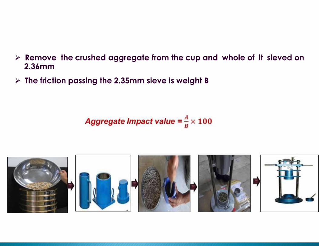
Remove the crushed aggregate from the cup and whole of it sieved on2.36mm
The friction passing the 2.35mm sieve is weight B
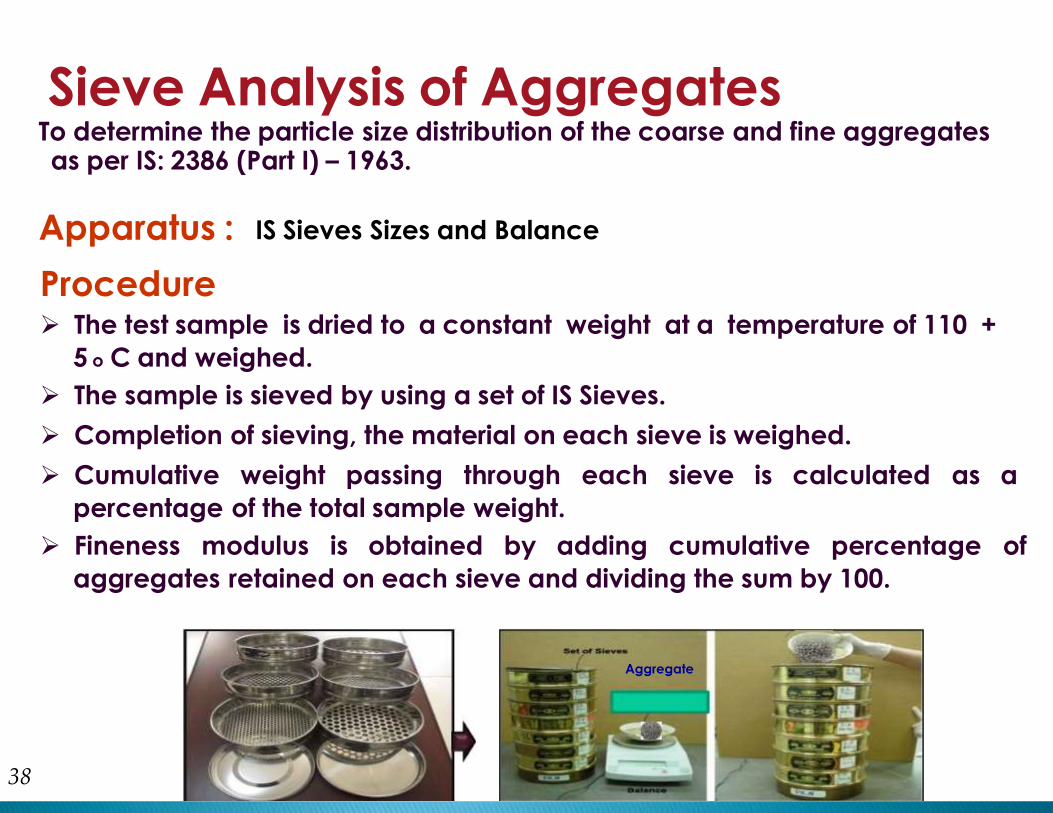
Sieve Analysis of AggregatesTo determine the particle size distribution of the coarse and fine aggregatesas per IS: 2386 (Part I) – 1963.
Apparatus : IS Sieves Sizes and Balance
38
Procedure The test sample is dried to a constant weight at a temperature of 110 +
5 o C and weighed.
The sample is sieved by using a set of IS Sieves.
Completion of sieving, the material on each sieve is weighed.
Cumulative weight passing through each sieve is calculated as a
percentage of the total sample weight.
Fineness modulus is obtained by adding cumulative percentage of
aggregates retained on each sieve and dividing the sum by 100.
Aggregate

Slump
TestCompressive
Strength
Material Test in Laboratory
ConcreteMix Design
ConcreteTest
CompactionFactor
Test
Vee- -Bee
Test

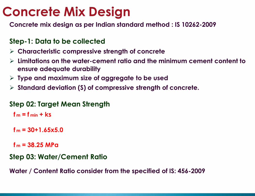
Water / Content Ratio consider from the specified of IS: 456-2009
Concrete Mix DesignConcrete mix design as per Indian standard method : IS 10262-2009
Step-1: Data to be collected
Characteristic compressive strength of concrete
Limitations on the water-cement ratio and the minimum cement content to
ensure adequate durability
Type and maximum size of aggregate to be used
Standard deviation (S) of compressive strength of concrete.
Step 02: Target Mean Strength
f m = f min + ks
f m = 30+1.65x5.0
f m = 38.25 MPa
Step 03: Water/Cement Ratio
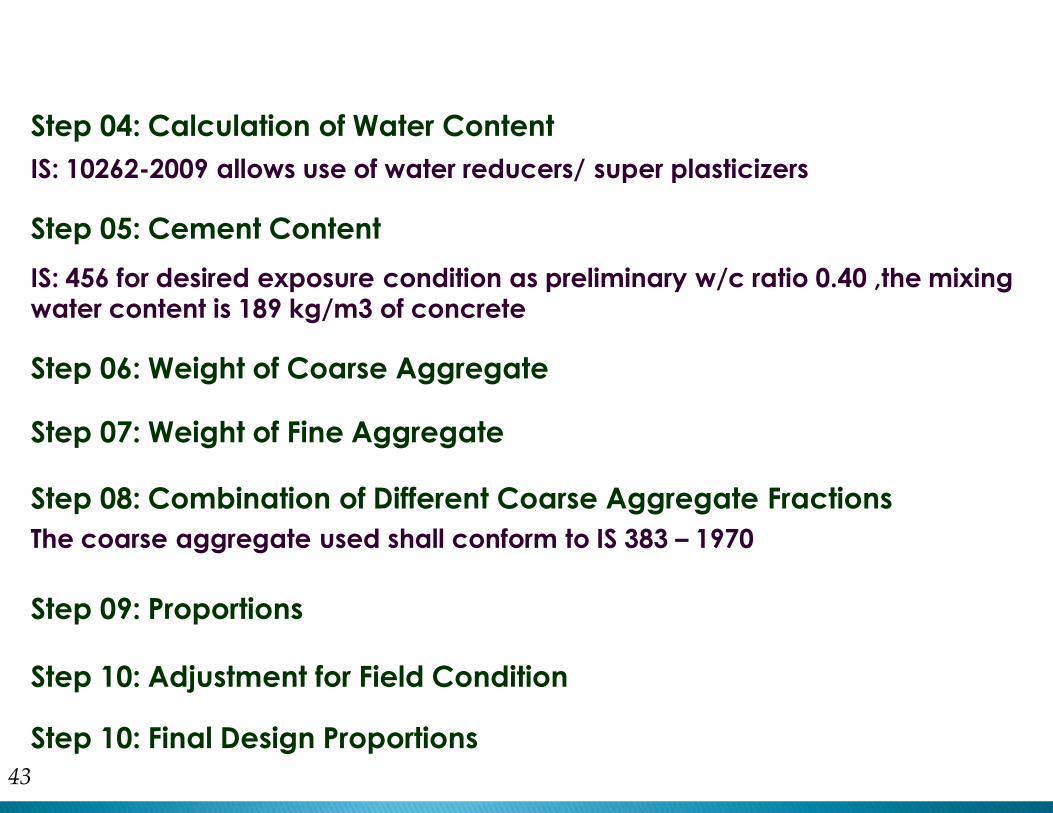
Step 04: Calculation of Water Content
IS: 10262-2009 allows use of water reducers/ super plasticizers
Step 05: Cement Content
43
IS: 456 for desired exposure condition as preliminary w/c ratio 0.40 ,the mixingwater content is 189 kg/m3 of concrete
Step 06: Weight of Coarse Aggregate
Step 07: Weight of Fine Aggregate
Step 08: Combination of Different Coarse Aggregate Fractions
The coarse aggregate used shall conform to IS 383 – 1970
Step 09: Proportions
Step 10: Adjustment for Field Condition
Step 10: Final Design Proportions

Slump TestFresh Concrete by Slump Test to determine the workability of fresh concreteas per IS: 1199 – 1959.
Apparatus: Slump Cone and Tamping Rod
Procedure
First, clean the inner surface of the empty mould and then apply oil to it
Set the mould on a horizontal non-porous and non-absorbent base plate
Fill the mould fully by pouring freshly mixed concrete in three equal layers
Stroke each layer 25 times with the standard tamping rod over the cross section
After stroking 25 times the top layer is struck off level, now lift the mould slowly in
the vertical direction without disturbing the concrete cone
Use the measuring scale to measure the difference level between the height of
the mould and the concrete sample.
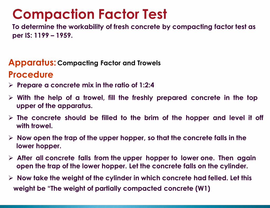
Compaction Factor TestTo determine the workability of fresh concrete by compacting factor test as
per IS: 1199 – 1959.
Apparatus: Compacting Factor and Trowels
Procedure Prepare a concrete mix in the ratio of 1:2:4
With the help of a trowel, fill the freshly prepared concrete in the top
upper of the apparatus.
The concrete should be filled to the brim of the hopper and level it off
with trowel.
Now open the trap of the upper hopper, so that the concrete falls in the
lower hopper.
After all concrete falls from the upper hopper to lower one. Then again
open the trap of the lower hopper. Let the concrete falls on the cylinder.
Now take the weight of the cylinder in which concrete had felled. Let this
weight be “The weight of partially compacted concrete (W1)

Empty the cylinder.
Now again, fill concrete in the cylinder in three layers with 25 blows for
each layer using tamping rod.
Fill concrete to the top of cylinder and scrape excess concrete above the
brim.
Now take the weight of the cylinder in which concrete we filled. Let this
weight be “The weight of fully compacted concrete (W2)
46
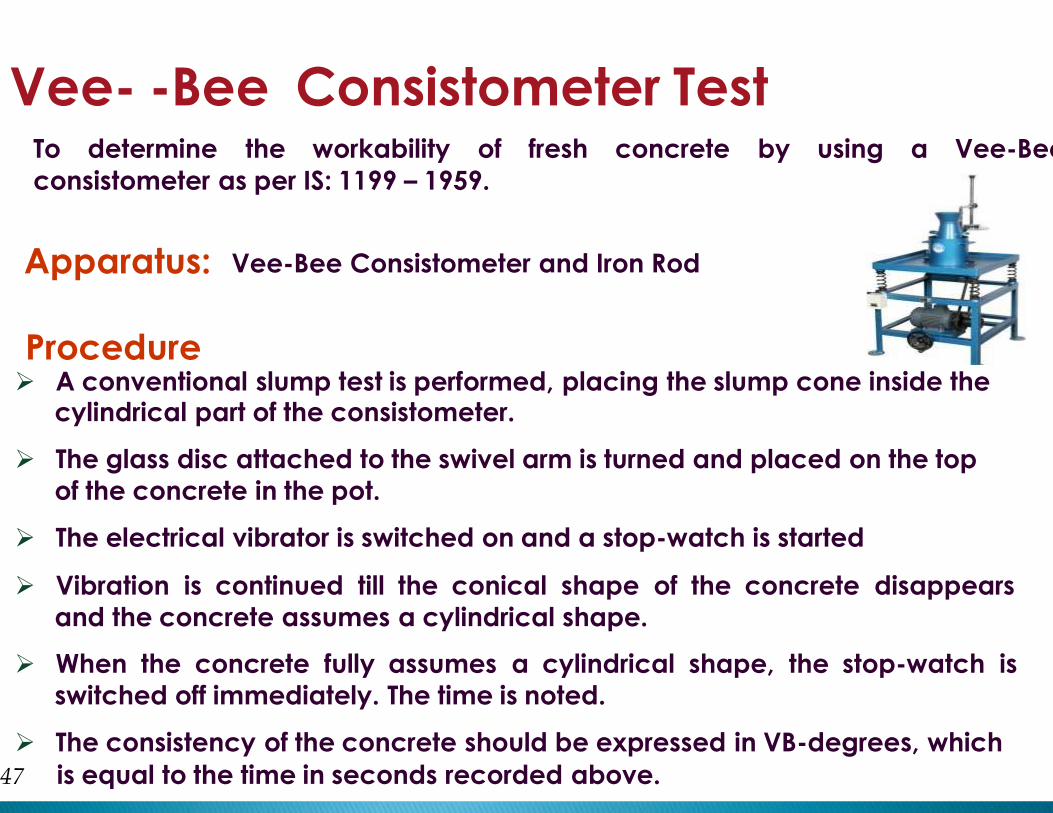
Vee- -Bee Consistometer TestTo determine the workability of fresh concrete by using a Vee-Bee
consistometer as per IS: 1199 – 1959.
Apparatus: Vee-Bee Consistometer and Iron Rod
Procedure A conventional slump test is performed, placing the slump cone inside the
cylindrical part of the consistometer.
The glass disc attached to the swivel arm is turned and placed on the top
of the concrete in the pot.
The electrical vibrator is switched on and a stop-watch is started
Vibration is continued till the conical shape of the concrete disappears
and the concrete assumes a cylindrical shape.
When the concrete fully assumes a cylindrical shape, the stop-watch is
switched off immediately. The time is noted.
The consistency of the concrete should be expressed in VB-degrees, which
47 is equal to the time in seconds recorded above.
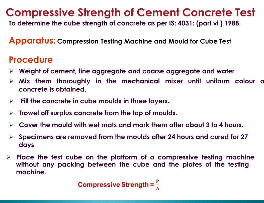
Compressive Strength of Cement Concrete TestTo determine the cube strength of concrete as per IS: 4031: (part vi ) 1988.
Apparatus: Compression Testing Machine and Mould for Cube Test
Procedure
Weight of cement, fine aggregate and coarse aggregate and water
Mix them thoroughly in the mechanical mixer until uniform colour of
concrete is obtained.
Fill the concrete in cube moulds in three layers.
Trowel off surplus concrete from the top of moulds.
Cover the mould with wet mats and mark them after about 3 to 4 hours.
Specimens are removed from the moulds after 24 hours and cured for 27
days
Place the test cube on the platform of a compressive testing machinewithout any packing between the cube and the plates of the testingmachine.

Material Test in Laboratory
Rebend
Test
49
Reinforcement
Test
ElongationTest
Pull outTest

Rebend TestProcedure to be followed: A mandrel is chosen according to thereinforcement diameter as mentioned in the table below –
Nominal Size of Specimen
Upto and including 10mm
Over 10 mm
Dia of mandrel for Fe 415and Fe 500
5φ
7φ
Dia of mandrel for Fe 550
7φ
8φ
50
where φ is the diameter of the sample in mm.
Procedure The test sample is bent to an included angle of 135 o .
The bent piece is then kept immersed in water at 100 o for 30 minutes and
then allowed to cool.
The sample is then bent back to an included angle of 157.5 o .
The purpose of re-bend test is measure the effect of strain ageing on steel
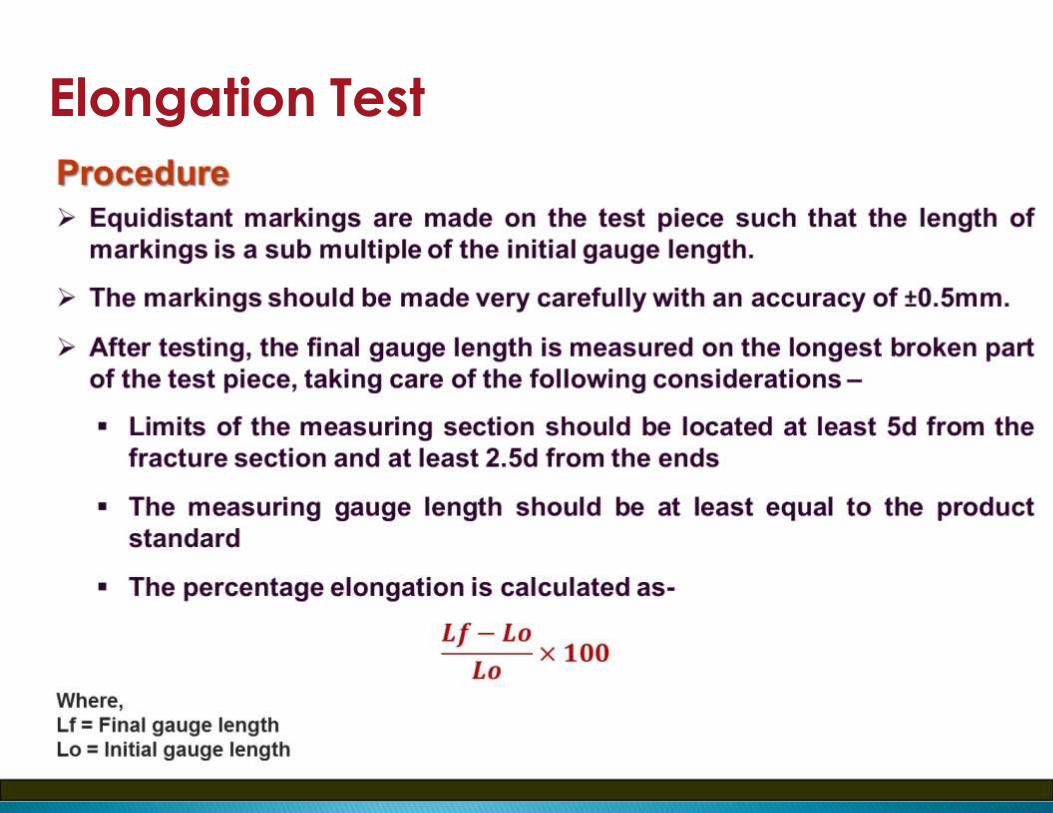
Elongation Test

Elongation percent (min)
Fe 415
14.5
Fe 500
12
Fe 550
8
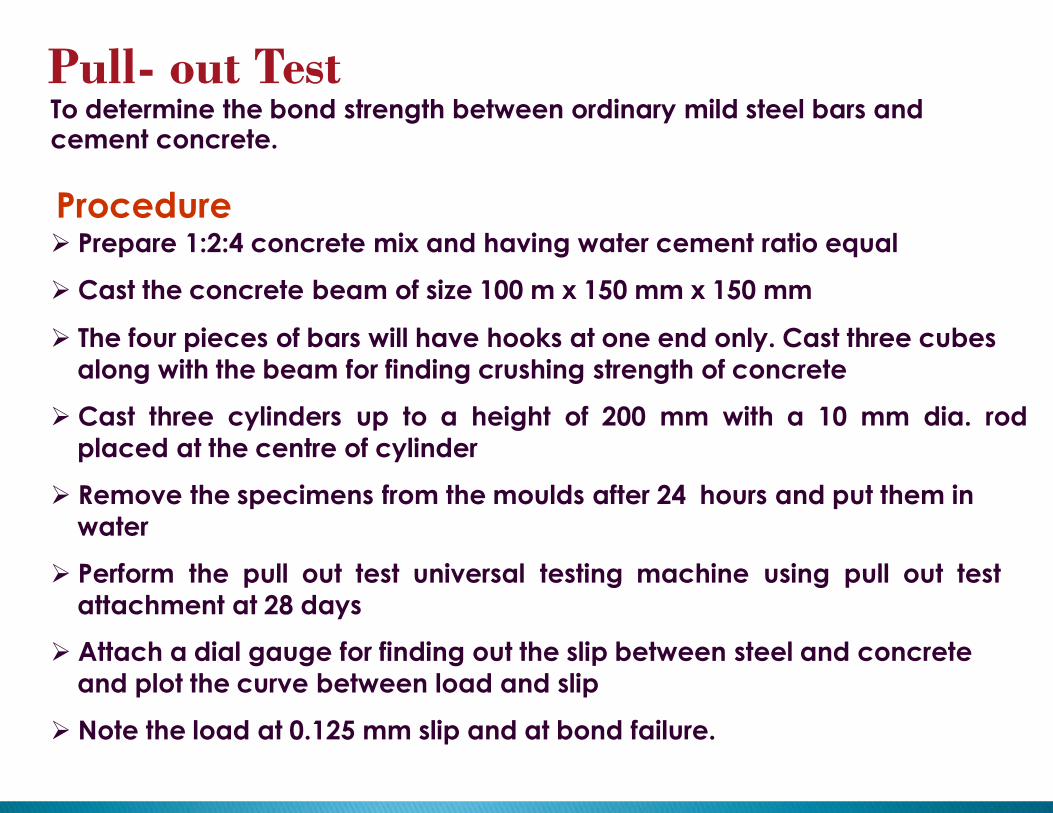
Pull- out TestTo determine the bond strength between ordinary mild steel bars andcement concrete.
Procedure Prepare 1:2:4 concrete mix and having water cement ratio equal
Cast the concrete beam of size 100 m x 150 mm x 150 mm
The four pieces of bars will have hooks at one end only. Cast three cubes
along with the beam for finding crushing strength of concrete
Cast three cylinders up to a height of 200 mm with a 10 mm dia. rod
placed at the centre of cylinder
Remove the specimens from the moulds after 24 hours and put them in
water
Perform the pull out test universal testing machine using pull out test
attachment at 28 days
Attach a dial gauge for finding out the slip between steel and concrete
and plot the curve between load and slip
Note the load at 0.125 mm slip and at bond failure.
55
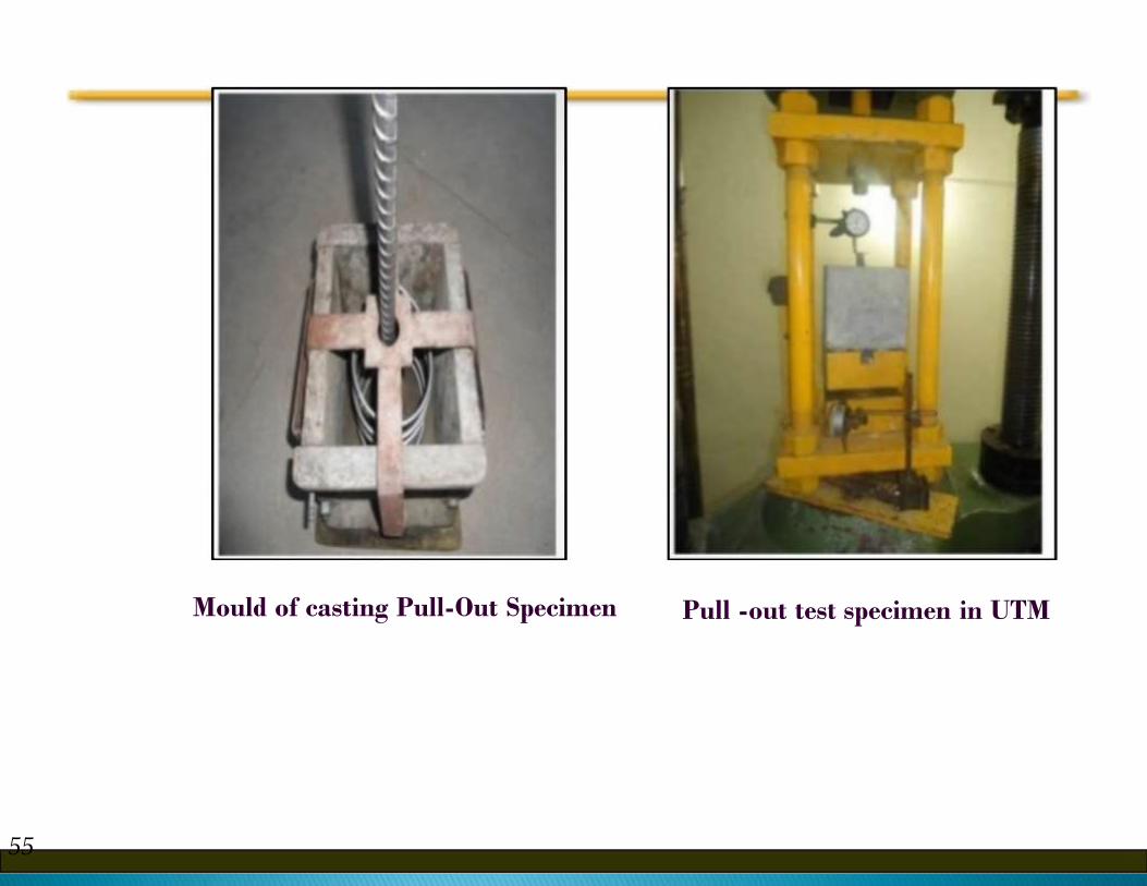
Mould of casting Pull-Out Specimen Pull -out test specimen in UTM

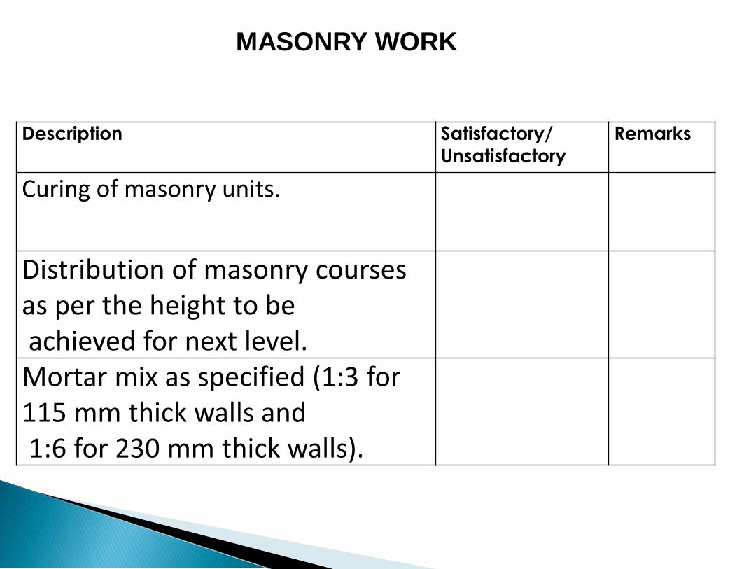
Description Satisfactory/
Unsatisfactory
Remarks
Curing of masonry units.
Distribution of masonry courses as per the height to beachieved for next level. Mortar mix as specified (1:3 for 115 mm thick walls and1:6 for 230 mm thick walls).
MASONRY WORK
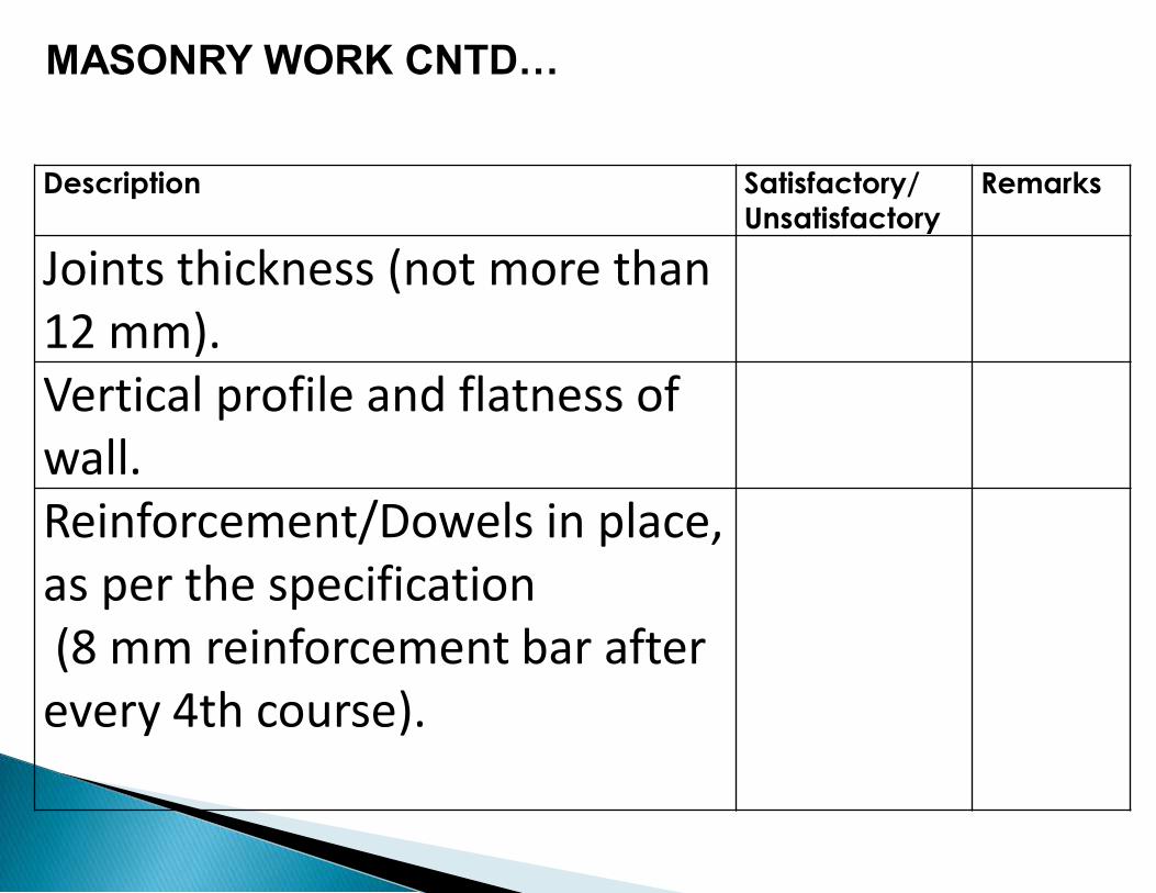
Description Satisfactory/
Unsatisfactory
Remarks
Joints thickness (not more than 12 mm). Vertical profile and flatness of wall. Reinforcement/Dowels in place, as per the specification(8 mm reinforcement bar after
every 4th course).
MASONRY WORK CNTD…

Description Satisfactory/
Unsatisfactory
Remarks
Joints even and racked.
Door/window openings as per drawing. Lintel beams provided as per drawing.
MASONRY WORK CNTD…
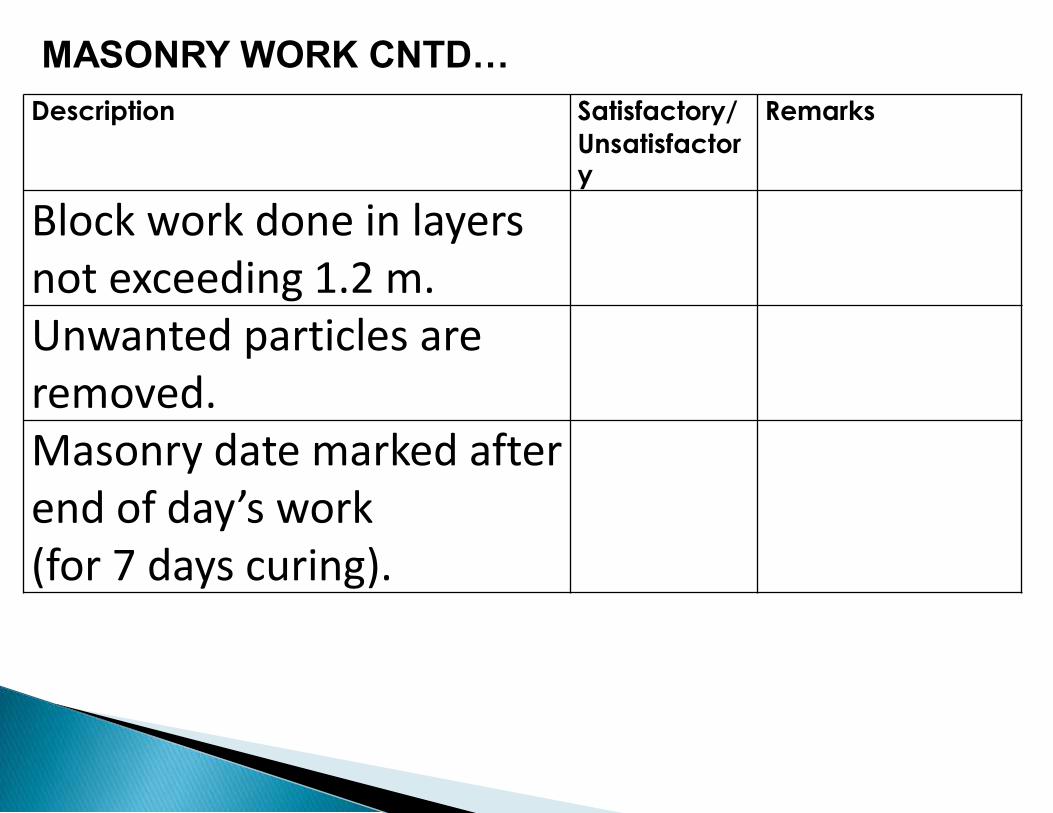
Description Satisfactory/
Unsatisfactory
Remarks
Block work done in layers not exceeding 1.2 m. Unwanted particles are removed. Masonry date marked after end of day’s work (for 7 days curing).
MASONRY WORK CNTD…

PLASTER WORK
Description Satisfactory/
Unsatisfactory
Remarks
Double Scaffolding for plastering
wall
Wetting masonry surface before
plastering
Mortar mix as specified (1:3 for
115 mm thick walls and 1:6 for
230 mm thick walls)

Description Satisfactory/
Unsatisfactory
Remarks
All holes and gaps are properly
filled
Under Coat : Plaster to be
finished to a true and plumb
surface and the surface shall be
left rough and furrowed 2 mm
deep
Finishing Coat : Check final
finish & grooves as per drawing
PLASTER WORK CNTD…
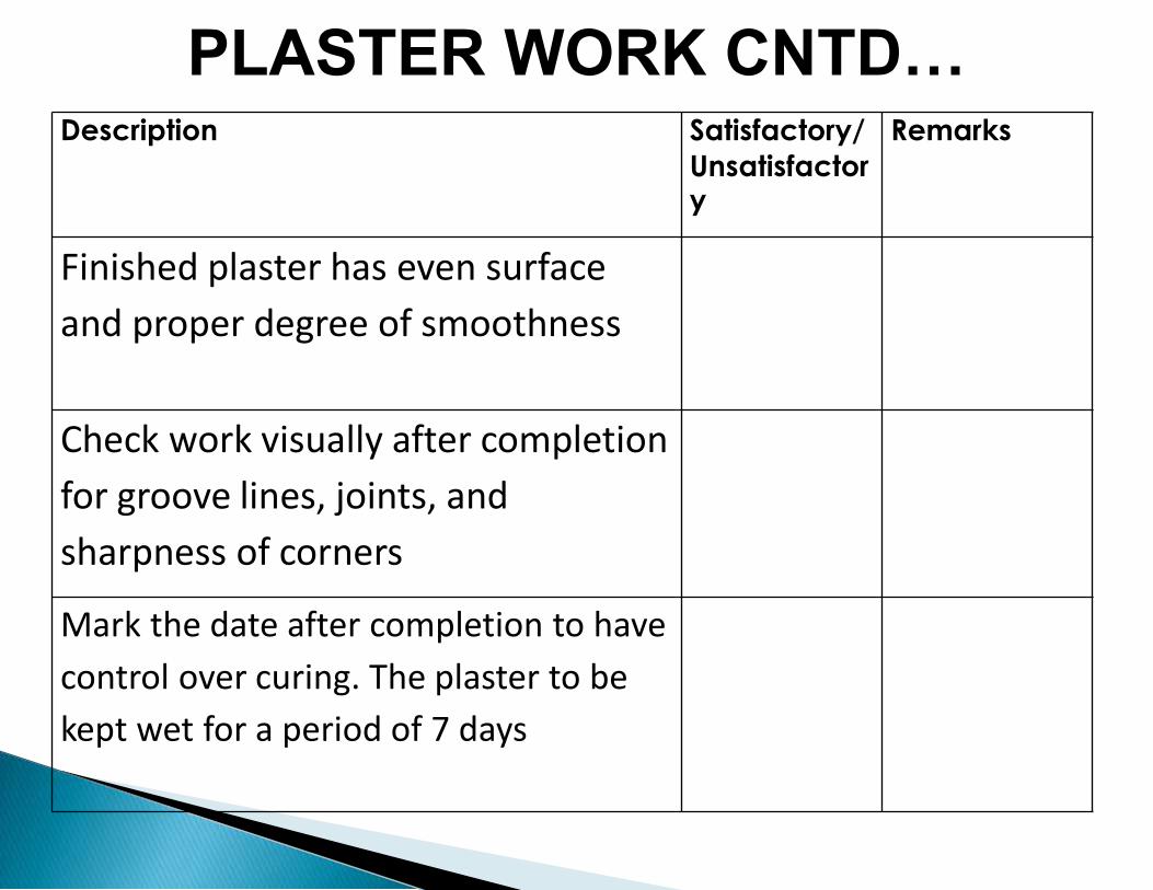
Description Satisfactory/
Unsatisfactory
Remarks
Finished plaster has even surface
and proper degree of smoothness
Check work visually after completion
for groove lines, joints, and
sharpness of corners
Mark the date after completion to have
control over curing. The plaster to be
kept wet for a period of 7 days
PLASTER WORK CNTD…

Description Satisfactory/
Unsatisfactory
Remarks
Cleanliness and unwanted
particles cleared away.
Unwanted particles, dust, foreign material or any deposits of contaminants are removed. Required slope maintained.
PLASTER WORK CNTD…
Description Satisfactory/
Unsatisfactory
Remarks
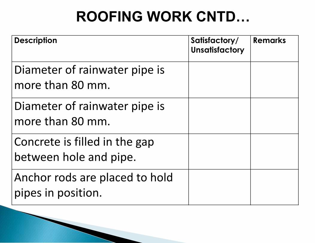
Diameter of rainwater pipe is more than 80 mm.
Diameter of rainwater pipe is more than 80 mm.
Concrete is filled in the gap between hole and pipe.
Anchor rods are placed to hold pipes in position.
ROOFING WORK CNTD…
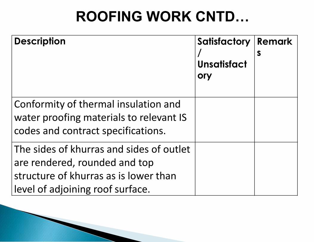
Description Satisfactory/
Unsatisfactory
Remarks
Conformity of thermal insulation and water proofing materials to relevant IS codes and contract specifications.
The sides of khurras and sides of outlet are rendered, rounded and top structure of khurras as is lower than level of adjoining roof surface.
ROOFING WORK CNTD…

Description Satisfactory/
Unsatisfactory
Remarks
The exposed surface of the gola is plastered with cement mortar or water proofing treatment as specified in contract.
The finished surface is cured at least for 7 days.
ROOFING WORK CNTD…
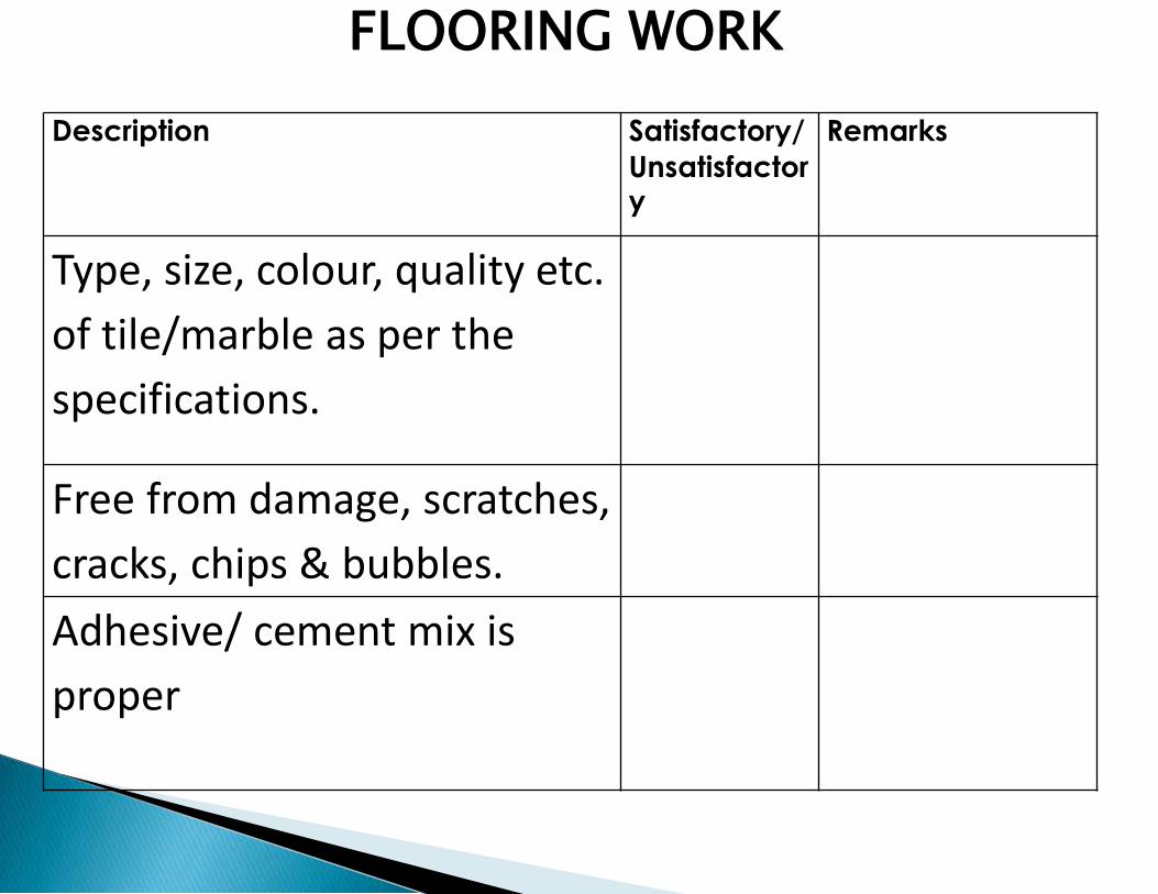
FLOORING WORK
Description Satisfactory/
Unsatisfactory
Remarks
Type, size, colour, quality etc.
of tile/marble as per the
specifications.
Free from damage, scratches,
cracks, chips & bubbles.
Adhesive/ cement mix is
proper
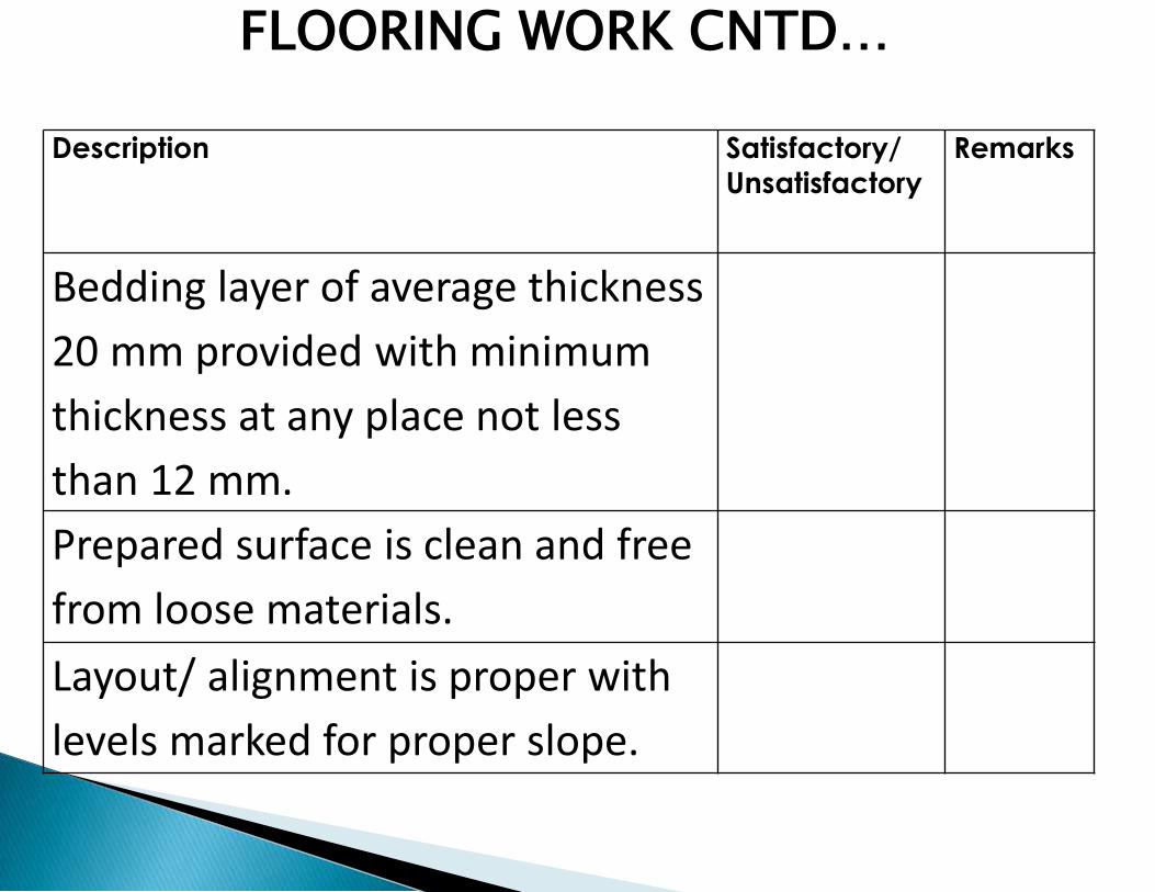
Description Satisfactory/
Unsatisfactory
Remarks
Bedding layer of average thickness
20 mm provided with minimum
thickness at any place not less
than 12 mm.
Prepared surface is clean and free
from loose materials.
Layout/ alignment is proper with
levels marked for proper slope.
FLOORING WORK CNTD…

Description Satisfactory/
Unsatisfactory
Remarks
Machine is used or cutting
marble/ tiles for uniformity and
edges are even and at right angle.
Proper finishing around drains,
switches & fittings is done.
Regular & continuous joints with
neat appearance.
FLOORING WORK CNTD…
Description Satisfactory/
Unsatisfactory
Remarks
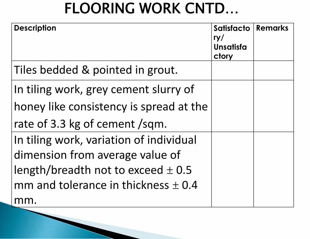
Tiles bedded & pointed in grout.
In tiling work, grey cement slurry of
honey like consistency is spread at the
rate of 3.3 kg of cement /sqm.
In tiling work, variation of individual dimension from average value of length/breadth not to exceed ± 0.5 mm and tolerance in thickness ± 0.4 mm.
FLOORING WORK CNTD…