![[2] compl-alg](https://static.fdocuments.us/doc/165x107/55cf8df5550346703b8d16ff/2-compl-alg.jpg)
COMPL OF WORKS1
23
About Me 1 Bachelors Degree in Mechanical Engineering -Graduated in 1992. 24 years experience in Oil and Gas Industry. Presently working as Head of Mechanical Static in PETRONAS Carigali in the Production International Division. Technical Authority of International Operations in various part of the world. Worked in Various Capacities - Mechanical Design Engineer, Project Execution & Commissioning Experienced in Piping, pipeline, pressure vessel, tanks and mechanical static equipment Won various innovation Awards & HSE Award. Following are some of the works done over the years
-
Upload
jose-verghese-bijoy -
Category
Documents
-
view
98 -
download
0
Transcript of COMPL OF WORKS1
About Me
1
Bachelors Degree in Mechanical Engineering -Graduated in 1992.
24 years experience in Oil and Gas Industry.
Presently working as Head of Mechanical Static in PETRONAS Carigali
in the Production International Division.
Technical Authority of International Operations in various part of the
world.
Worked in Various Capacities - Mechanical Design Engineer, Project
Execution & Commissioning
Experienced in Piping, pipeline, pressure vessel, tanks and mechanical
static equipment
Won various innovation Awards & HSE Award.
Following are some of the works done over the years
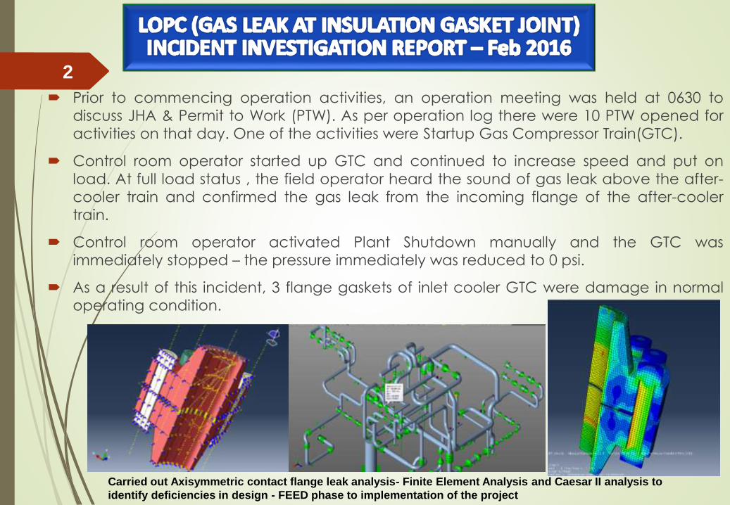
Prior to commencing operation activities, an operation meeting was held at 0630 to
discuss JHA & Permit to Work (PTW). As per operation log there were 10 PTW opened for
activities on that day. One of the activities were Startup Gas Compressor Train(GTC).
Control room operator started up GTC and continued to increase speed and put on
load. At full load status , the field operator heard the sound of gas leak above the after-
cooler train and confirmed the gas leak from the incoming flange of the after-cooler
train.
Control room operator activated Plant Shutdown manually and the GTC was
immediately stopped – the pressure immediately was reduced to 0 psi.
As a result of this incident, 3 flange gaskets of inlet cooler GTC were damage in normal
operating condition.
3/23/2016
2
Carried out Axisymmetric contact flange leak analysis- Finite Element Analysis and Caesar II analysis to
identify deficiencies in design - FEED phase to implementation of the project
3/23/2016
3 Underlying CausesDesign Engineering (DE):
• Failed to conduct a proper review of the stress analysis report and failed to recognize
the importance of the differential thermal load on dissimilar nozzle material.
• Failed to review standards during detail engineering. Data sheet of the insulating
gasket is incomplete and does not have the process design data.
• In the detailed engineering material selection did not follow manufacture standard for
the insulating gasket as Neophenolic can only installed in piping flanges of 300# or
below and temperature less than 107deg
Incompatible Goals (IG):
• Failed to communicate important issues on design (stress analysis & process
parameter) from detailed engineering to PCIC contractor.
• Failed on the part of management to bridge between detailed engineering phase and
PCIC phase
Error Enforcing Conditions (EC):
• Management Failed to review Special Item. The Insulation Gasket are special items,
however, these were treated as bulk material by the PCIC contractor.
• Verify Bolt tensioning calculation by the contractor. Bolting by the specialist flange
management contractor on critical test limit tie-in flanged joints were carried out
without proper calculations and review.
• Insufficient resources to conduct proper Line Design Review(LDR)
Hydrostatic load on vertical vessel Skid
3/23/2016
4
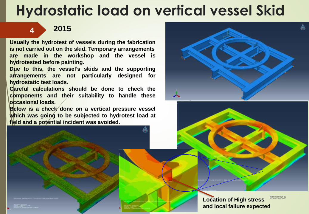
Usually the hydrotest of vessels during the fabrication
is not carried out on the skid. Temporary arrangements
are made in the workshop and the vessel is
hydrotested before painting.
Due to this, the vessel’s skids and the supporting
arrangements are not particularly designed for
hydrostatic test loads.
Careful calculations should be done to check the
components and their suitability to handle these
occasional loads.
Below is a check done on a vertical pressure vessel
which was going to be subjected to hydrotest load at
field and a potential incident was avoided.
Location of High stress
and local failure expected
2015
3/23/2016
5
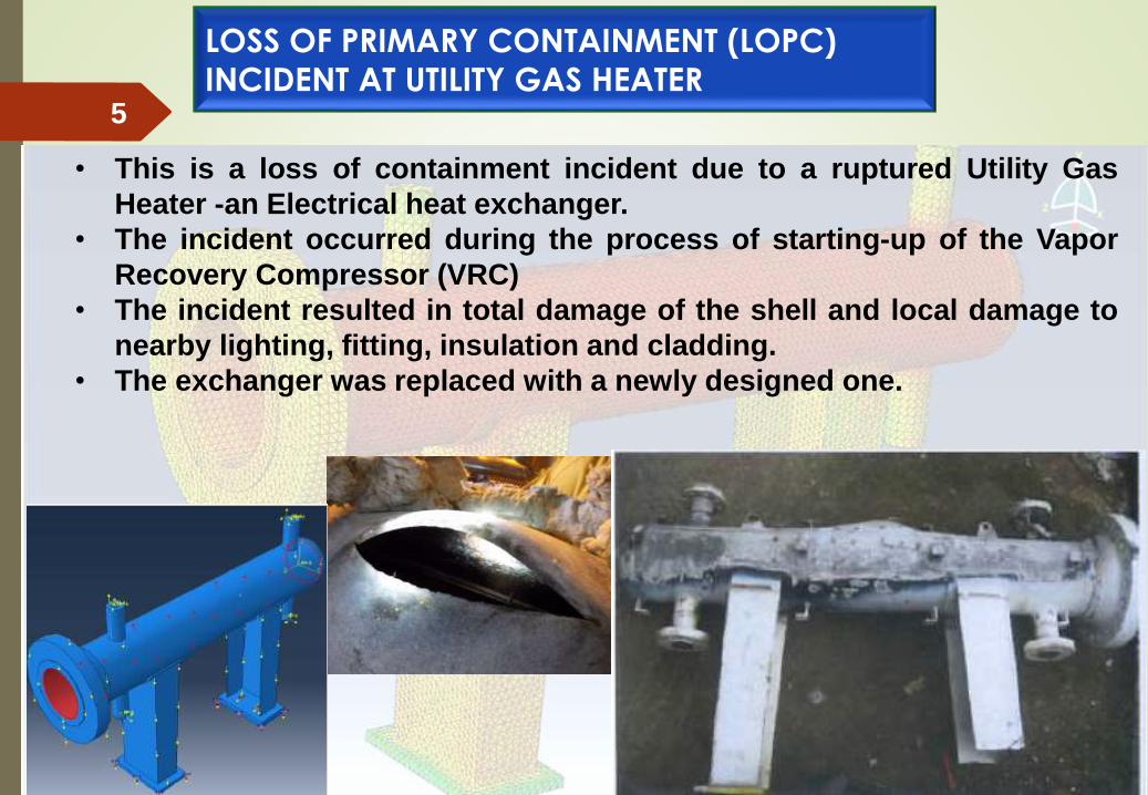
• This is a loss of containment incident due to a ruptured Utility Gas
Heater -an Electrical heat exchanger.
• The incident occurred during the process of starting-up of the Vapor
Recovery Compressor (VRC)
• The incident resulted in total damage of the shell and local damage to
nearby lighting, fitting, insulation and cladding.
• The exchanger was replaced with a newly designed one.
LOSS OF PRIMARY CONTAINMENT (LOPC)
INCIDENT AT UTILITY GAS HEATER

3/23/2016
6• Fortunately, there was no one near the equipment during the incident or
it could have resulted in a more severe impact as the incident involved a
high-pressure release of natural gas at 90 BarG.
• It was also fortunate that the release was stopped through manual
activation of Emergency Shut Down (ESD) before it could get in contact
with any source of ignition.
• This study was trigger by photographical evidences of the site which had
a heat exchanger with missing bolts on the support.
LOSS OF PRIMARY CONTAINMENT (LOPC)
INCIDENT AT UTILITY GAS HEATER
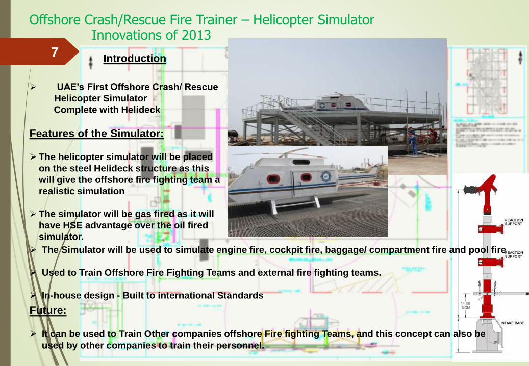
Offshore Crash/Rescue Fire Trainer – Helicopter Simulator
7
UAE’s First Offshore Crash/ Rescue
Helicopter Simulator
Complete with Helideck
Features of the Simulator:
The helicopter simulator will be placed
on the steel Helideck structure as this
will give the offshore fire fighting team a
realistic simulation
The simulator will be gas fired as it will
have HSE advantage over the oil fired
simulator.
Future:
It can be used to Train Other companies offshore Fire fighting Teams, and this concept can also be
used by other companies to train their personnel.
The Simulator will be used to simulate engine fire, cockpit fire, baggage/ compartment fire and pool fire
Used to Train Offshore Fire Fighting Teams and external fire fighting teams.
In-house design - Built to international Standards
Introduction
Innovations of 2013
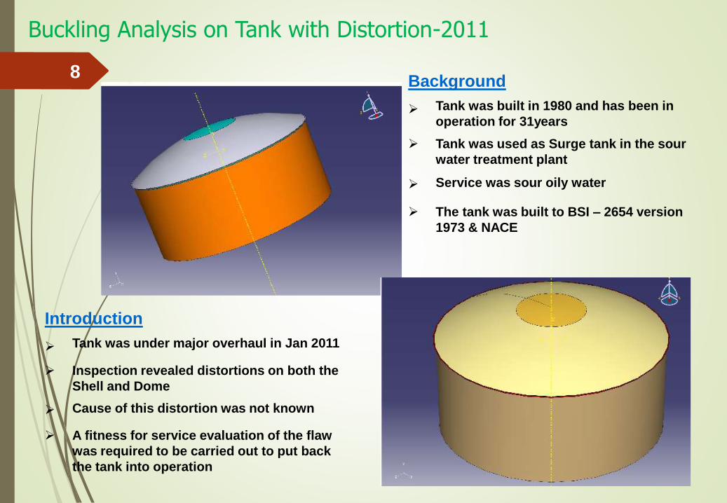
Buckling Analysis on Tank with Distortion-2011
8Background
Tank was built in 1980 and has been in
operation for 31years
Service was sour oily water
Tank was used as Surge tank in the sour
water treatment plant
The tank was built to BSI – 2654 version
1973 & NACE
Introduction
Tank was under major overhaul in Jan 2011
Cause of this distortion was not known
Inspection revealed distortions on both the
Shell and Dome
A fitness for service evaluation of the flaw
was required to be carried out to put back
the tank into operation
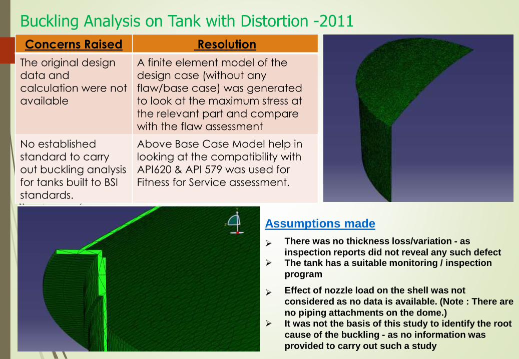
Buckling Analysis on Tank with Distortion -2011
9
Assumptions made
There was no thickness loss/variation - as
inspection reports did not reveal any such defectThe tank has a suitable monitoring / inspection
program
Concerns Raised Resolution
The original design
data and
calculation were not
available
A finite element model of the
design case (without any
flaw/base case) was generated
to look at the maximum stress at
the relevant part and compare
with the flaw assessment
No established
standard to carry
out buckling analysis
for tanks built to BSI
standards.
Above Base Case Model help in
looking at the compatibility with
API620 & API 579 was used for
Fitness for Service assessment.
Effect of nozzle load on the shell was not
considered as no data is available. (Note : There are
no piping attachments on the dome.)It was not the basis of this study to identify the root
cause of the buckling - as no information was
provided to carry out such a study
Buckling Analysis on Tank with Distortions
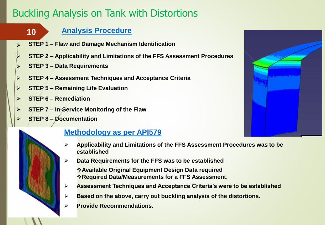
10 Analysis Procedure
STEP 1 – Flaw and Damage Mechanism Identification
STEP 3 – Data Requirements
STEP 2 – Applicability and Limitations of the FFS Assessment Procedures
STEP 4 – Assessment Techniques and Acceptance Criteria
STEP 5 – Remaining Life Evaluation
STEP 6 – Remediation
STEP 7 – In-Service Monitoring of the Flaw
STEP 8 – Documentation
Methodology as per API579
Applicability and Limitations of the FFS Assessment Procedures was to be
established
Data Requirements for the FFS was to be established
Available Original Equipment Design Data required
Required Data/Measurements for a FFS Assessment.
Assessment Techniques and Acceptance Criteria’s were to be established
Based on the above, carry out buckling analysis of the distortions.
Provide Recommendations.
Buckling Analysis in Tank with Distortion
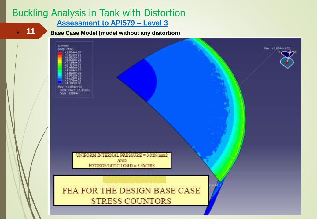
11Assessment to API579 – Level 3
Base Case Model (model without any distortion)
Buckling Analysis on Tank
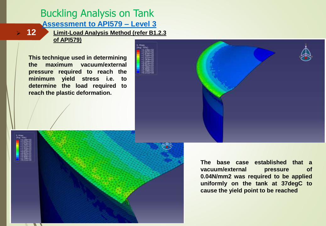
12Assessment to API579 – Level 3
Limit-Load Analysis Method (refer B1.2.3
of API579)
This technique used in determining
the maximum vacuum/external
pressure required to reach the
minimum yield stress i.e. to
determine the load required to
reach the plastic deformation.
The base case established that a
vacuum/external pressure of
0.04N/mm2 was required to be applied
uniformly on the tank at 37degC to
cause the yield point to be reached
Buckling Analysis in Tank
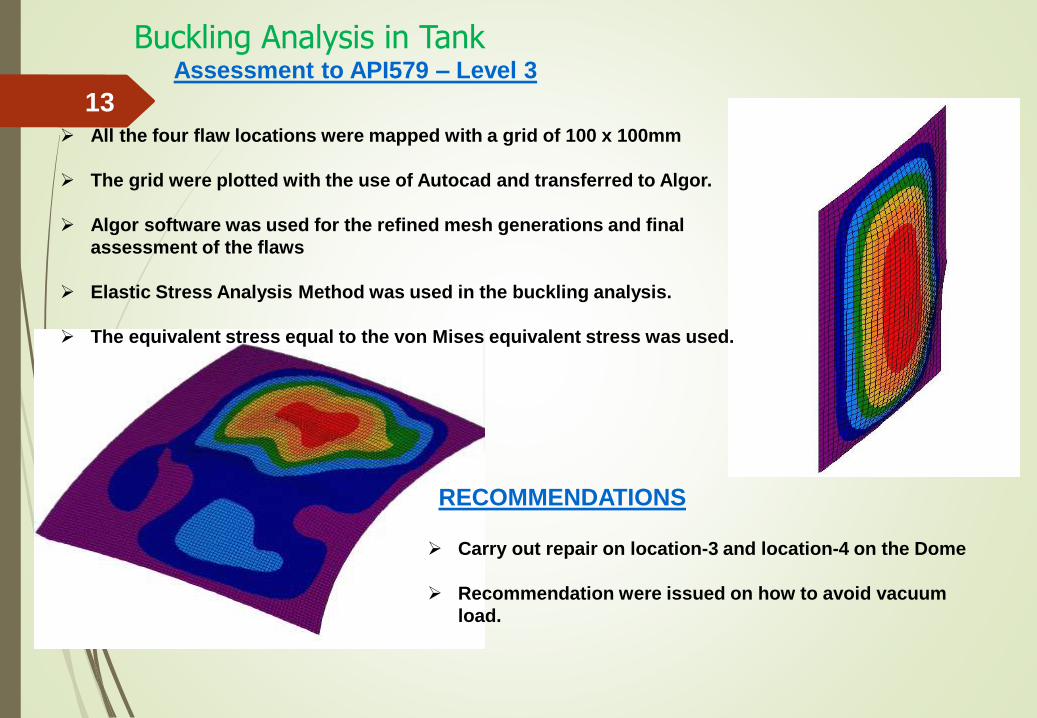
13 All the four flaw locations were mapped with a grid of 100 x 100mm
The grid were plotted with the use of Autocad and transferred to Algor.
Algor software was used for the refined mesh generations and final
assessment of the flaws
Elastic Stress Analysis Method was used in the buckling analysis.
The equivalent stress equal to the von Mises equivalent stress was used.
Assessment to API579 – Level 3
Carry out repair on location-3 and location-4 on the Dome
Recommendation were issued on how to avoid vacuum
load.
RECOMMENDATIONS
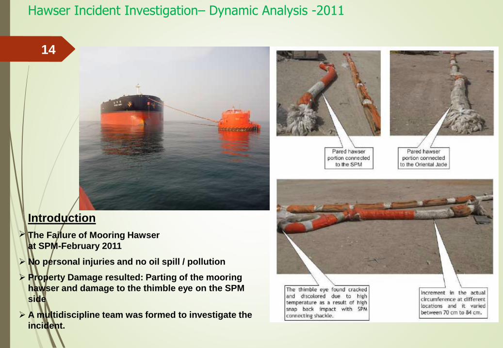
Hawser Incident Investigation– Dynamic Analysis -2011
14
The Failure of Mooring Hawser
at SPM-February 2011
No personal injuries and no oil spill / pollution
Property Damage resulted: Parting of the mooring
hawser and damage to the thimble eye on the SPM
side
A multidiscipline team was formed to investigate the
incident.
Introduction
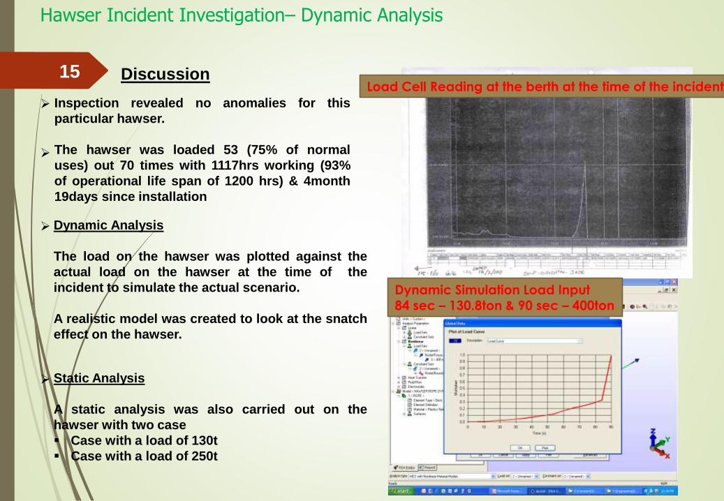
Hawser Incident Investigation– Dynamic Analysis
15
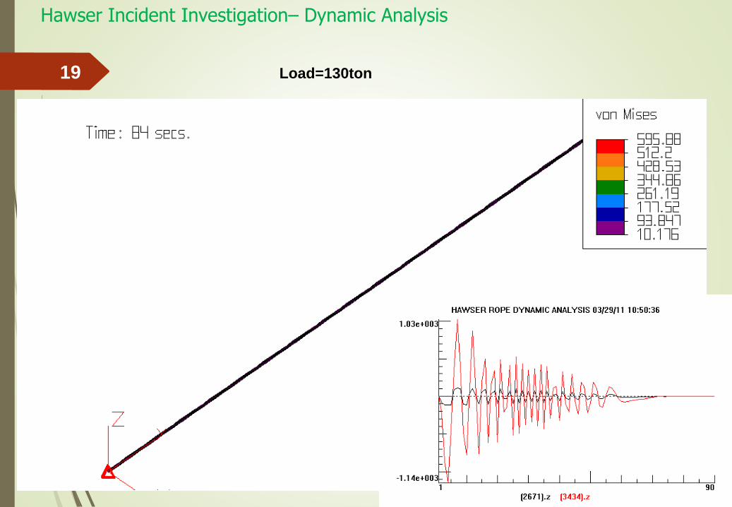
Dynamic Analysis
The load on the hawser was plotted against the
actual load on the hawser at the time of the
incident to simulate the actual scenario.
A realistic model was created to look at the snatch
effect on the hawser.
Load Cell Reading at the berth at the time of the incident
Dynamic Simulation Load Input
84 sec – 130.8ton & 90 sec – 400ton
Inspection revealed no anomalies for this
particular hawser.
The hawser was loaded 53 (75% of normal
uses) out 70 times with 1117hrs working (93%
of operational life span of 1200 hrs) & 4month
19days since installation
Static Analysis
A static analysis was also carried out on the
hawser with two case
Case with a load of 130t
Case with a load of 250t
Discussion
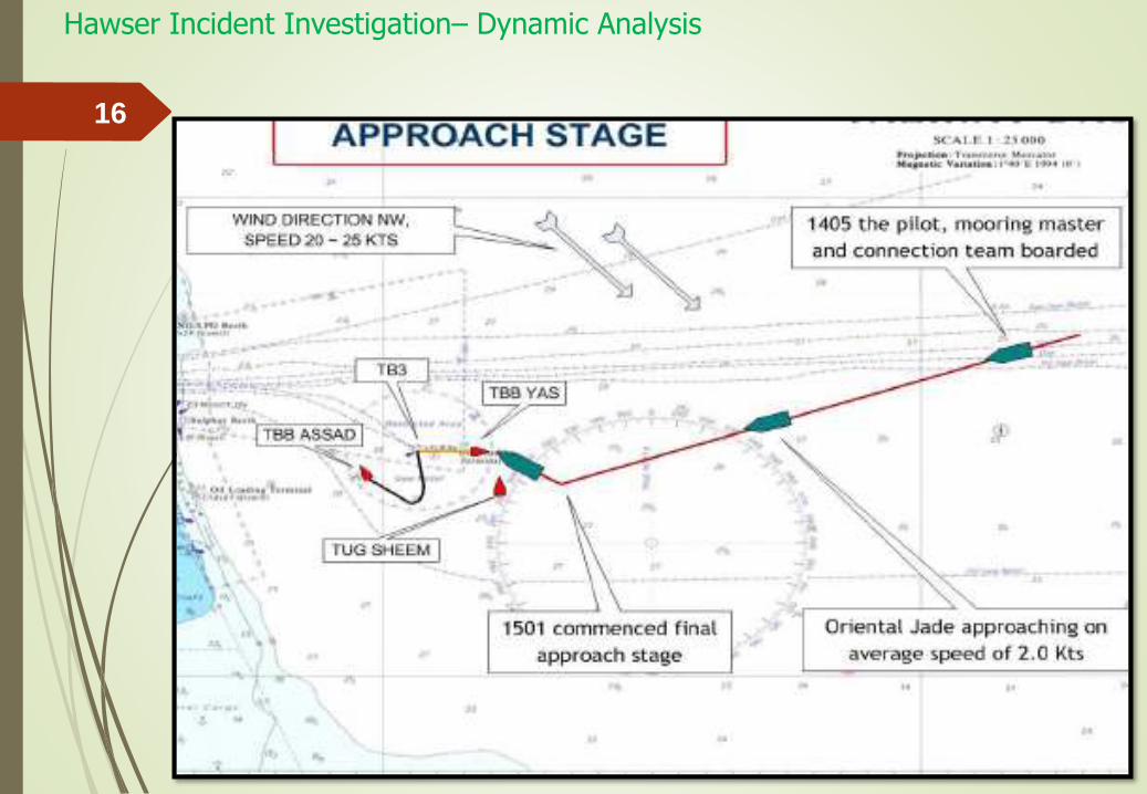
Hawser Incident Investigation– Dynamic Analysis
16
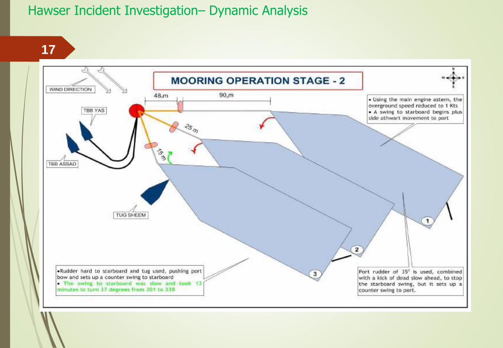
Hawser Incident Investigation– Dynamic Analysis
17
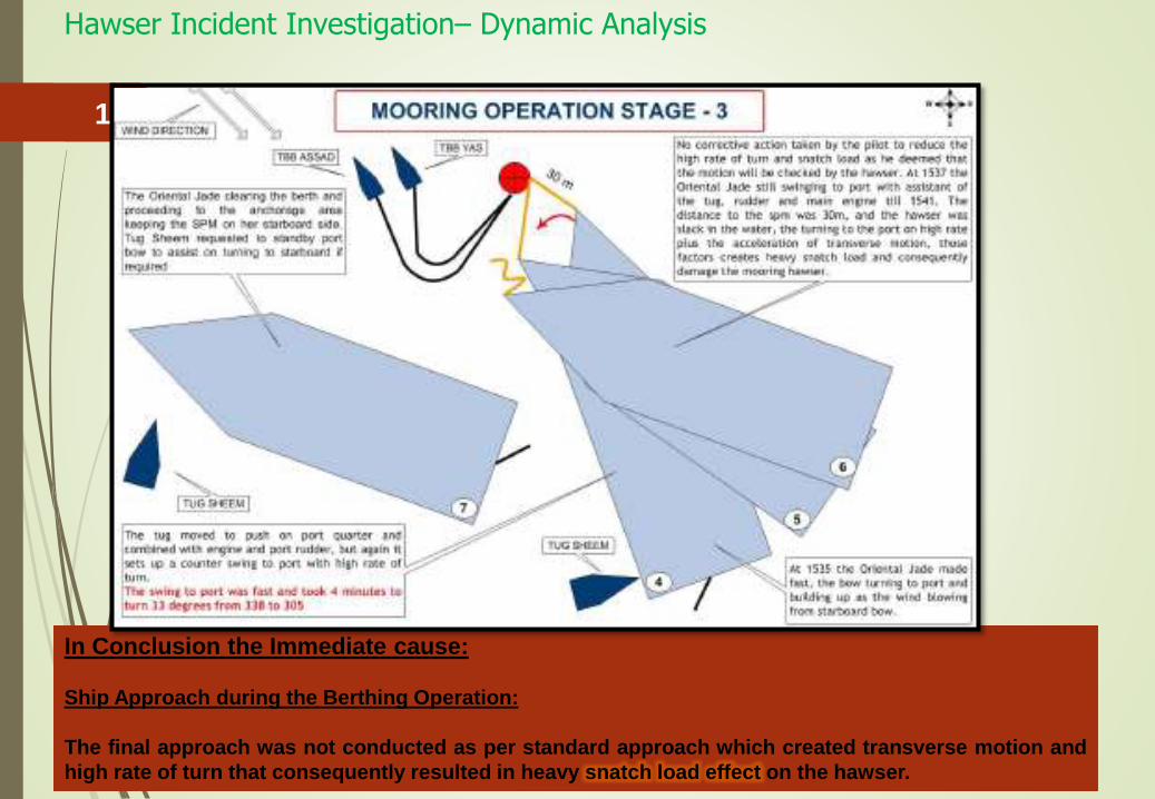
In Conclusion the Immediate cause:
Ship Approach during the Berthing Operation:
The final approach was not conducted as per standard approach which created transverse motion and
high rate of turn that consequently resulted in heavy snatch load effect on the hawser.
Hawser Incident Investigation– Dynamic Analysis
18
Hawser Incident Investigation– Dynamic Analysis
19 Load=130ton
Innovation -2009GRE Piggable Pipeline – ASME B31.4
20
Barred TeeBarred Tee
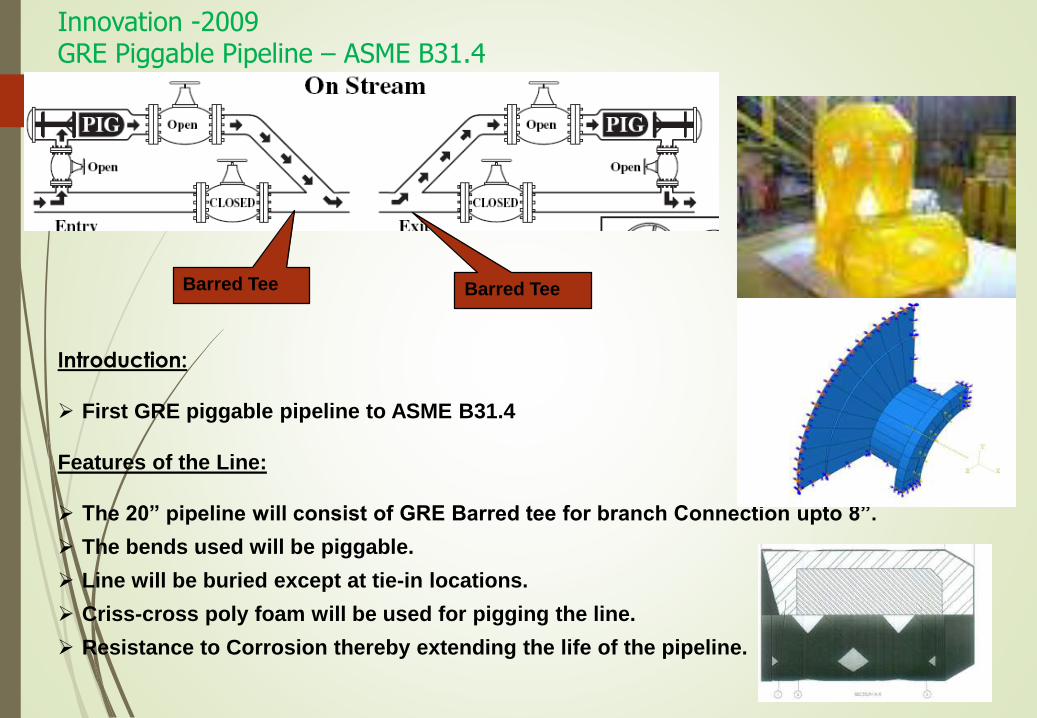
Introduction:
First GRE piggable pipeline to ASME B31.4
Features of the Line:
The 20” pipeline will consist of GRE Barred tee for branch Connection upto 8”.
The bends used will be piggable.
Line will be buried except at tie-in locations.
Criss-cross poly foam will be used for pigging the line.
Resistance to Corrosion thereby extending the life of the pipeline.
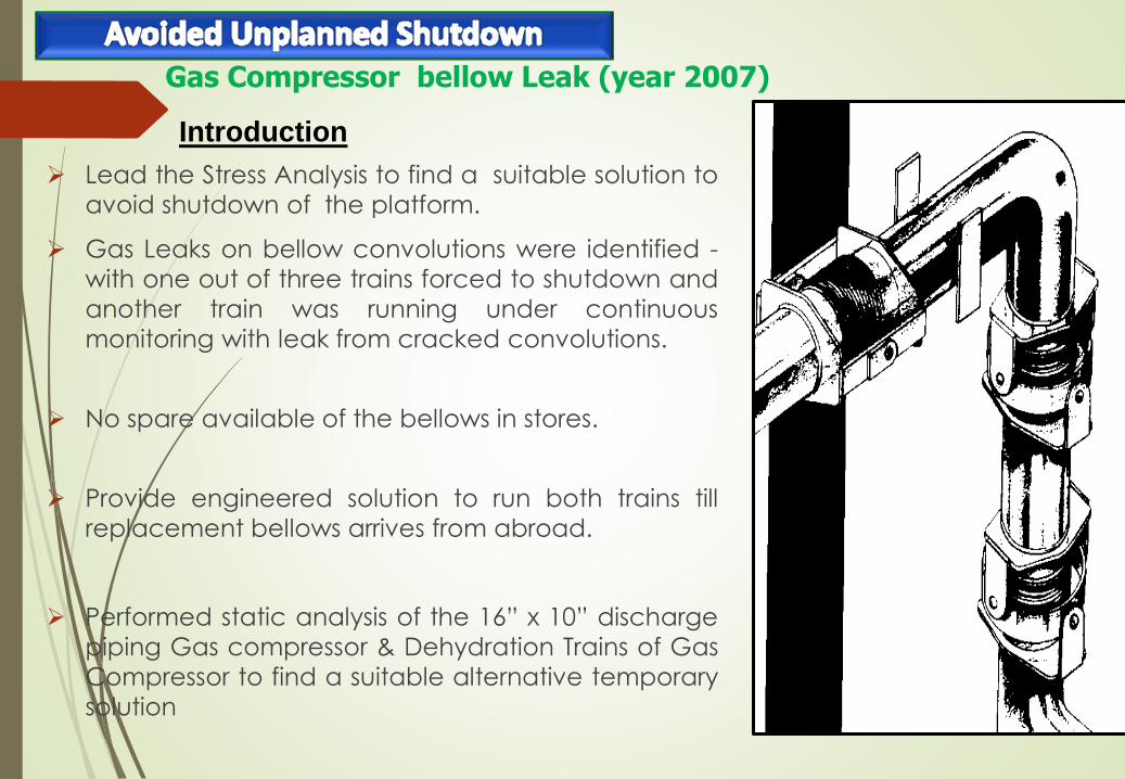
Lead the Stress Analysis to find a suitable solution to
avoid shutdown of the platform.
Gas Leaks on bellow convolutions were identified -
with one out of three trains forced to shutdown and
another train was running under continuous
monitoring with leak from cracked convolutions.
No spare available of the bellows in stores.
Provide engineered solution to run both trains till
replacement bellows arrives from abroad.
Performed static analysis of the 16” x 10” discharge
piping Gas compressor & Dehydration Trains of Gas
Compressor to find a suitable alternative temporary
solution
Gas Compressor bellow Leak (year 2007)
Introduction
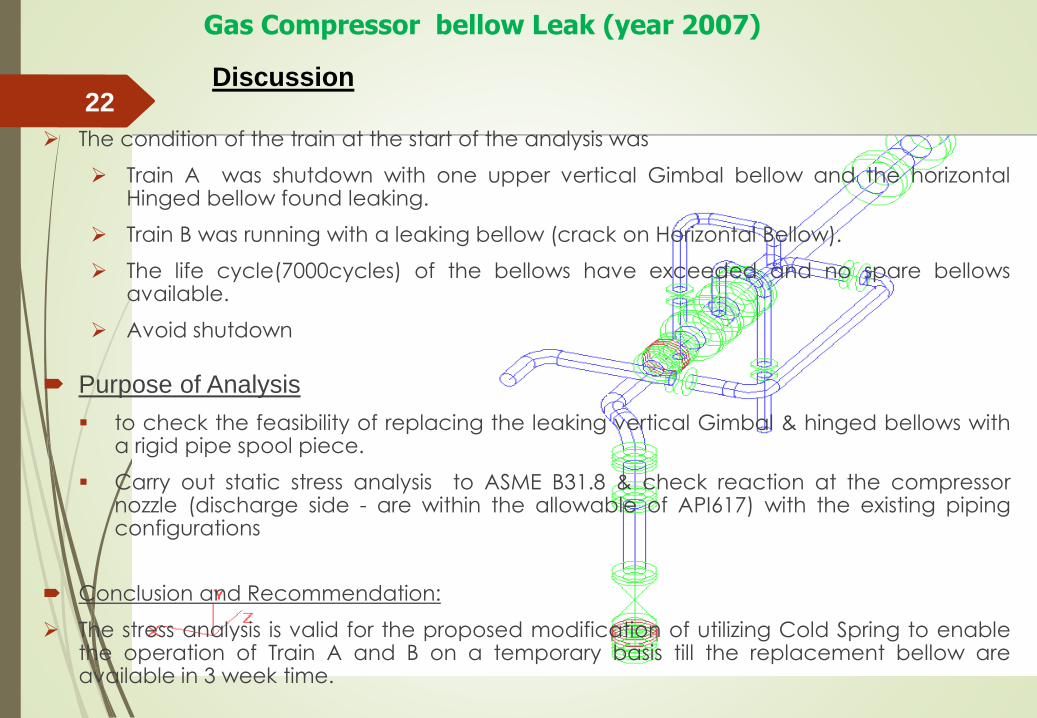
The condition of the train at the start of the analysis was
Train A was shutdown with one upper vertical Gimbal bellow and the horizontalHinged bellow found leaking.
Train B was running with a leaking bellow (crack on Horizontal Bellow).
The life cycle(7000cycles) of the bellows have exceeded and no spare bellowsavailable.
Avoid shutdown
Purpose of Analysis
to check the feasibility of replacing the leaking vertical Gimbal & hinged bellows witha rigid pipe spool piece.
Carry out static stress analysis to ASME B31.8 & check reaction at the compressornozzle (discharge side - are within the allowable of API617) with the existing pipingconfigurations
Conclusion and Recommendation:
The stress analysis is valid for the proposed modification of utilizing Cold Spring to enablethe operation of Train A and B on a temporary basis till the replacement bellow areavailable in 3 week time.
22
Gas Compressor bellow Leak (year 2007)
Discussion

FINITE ELEMENT ANALYSIS -2002FITNESS FOR SERVICE
23
Scaled Acad Model of Spheroid
Drawn by Bijoy
Featured article & Picture from Company
Magazine
Thank You