COMPETENT THIRD PERSON REPORT
29
Electrostatic Loudspeakers 1 / 39 COMPETENT THIRD PERSON REPORT ELECTROSTATIC LOUDSPEAKERS Report to: Craig Evans Immersion Technology International plc Project #: 6301 Report: Full final (39 pages) Date: 19 June 2006 Gregory Keith Cambrell, B.E.(Hons), B.Sc.(Hons), Ph.D.
Transcript of COMPETENT THIRD PERSON REPORT

Electrostatic Loudspeakers
1 / 39
COMPETENT THIRD PERSON REPORT
ELECTROSTATIC LOUDSPEAKERS
Report to:
Craig Evans
Immersion Technology International plc
Project #: 6301
Report: Full final (39 pages)
Date: 19 June 2006
Gregory Keith Cambrell, B.E.(Hons), B.Sc.(Hons), Ph.D.

Electrostatic Loudspeakers
2 / 39
EXECUTIVE SUMMARY
Immersion Technology International plc (‘Immersion’) has developed an alternative electrostatic
type of loudspeaker to compete directly with the existing dominant magnetostatic (more
commonly called moving-coil electrodynamic) type of loudspeaker. Amongst other significant
advantages that an electrostatic loudspeaker has over a conventional magnetostatic loudspeaker,
the most distinguishing and noteworthy feature for the loudspeaker market is that the structure of
an electrostatic panel is inherently thin, typically 10 mm or less.
There are several significant theoretical advantages to electrostatic loudspeakers compared to
magnetostatic loudspeakers but in the past most of the advantages could not be fully realised
until certain physical constraints were overcome [1, 2]. Immersion has successfully realised
these advantages and is now poised to challenge the loudspeaker market.
In simple terms, Immersion has now attained what was previously regarded as nearly impossible
to attain for an electrostatic loudspeaker because of numerous improvements in the materials of
construction and the techniques of manufacture. Until now electrostatic loudspeakers have
enjoyed limited acceptance in the marketplace; however, once properly commercialised,
Immersion will be a viable competitor against not only existing electrostatic loudspeakers but
also conventional magnetostatic loudspeakers.
Immersion has patented a number of electronic and construction techniques for improving the
performance of electrostatic loudspeakers and facilitating their manufacture. They have reached
the point of development where electrostatic loudspeakers of various sizes can be a superior yet
cheaper alternative to the existing magnetostatic loudspeakers of comparable size for many
applications.
By comparison with magnetostatic loudspeakers, the theoretical advantages of electrostatic
loudspeakers include
• linear (distortionless) transduction principle
• uniform force per unit area of diaphragm
• low-mass diaphragm allowing superior high-frequency performance
• radiation characteristics (including low-frequency acoustical resistance) controlled by the
extent and shape of diaphragm area
• baffles (as with conventional loudspeakers) of various sizes and shapes (possibly adjustable)
may be incorporated to further control the low-frequency performance
• inherently thin construction
• relatively low cost of required materials
Immersion has developed several prototype electrostatic loudspeaker models. Immersion’s
larger models have been evaluated and compared to three commercially-available electrostatic
loudspeakers of similar size yet costing up to double the estimated recommended retail price of
Immersion’s models. Measurements and listening tests have shown that not only have the
theoretical advantages of electrostatic loudspeakers been achieved in Immersion’s new models
but also their performance exceeds that of the three commercially-available products.
Furthermore, Immersion’s smaller models have shown outstanding performance against
conventional loudspeakers of similar size.

Electrostatic Loudspeakers
3 / 39
Mass production of Immersion’s prototype models with their patented improvements in
construction techniques is expected to produce reliable high-performance products with major
cost benefits compared to conventional loudspeaker products in many areas of application.
Independent market appraisals have shown the enormous potential for Immersion’s thin
electrostatic loudspeaker technology to compete with conventional loudspeakers in market areas
ranging from high-end audio to home and car entertainment.

Electrostatic Loudspeakers
4 / 39
TABLE OF CONTENTS
Executive Summary
Table of Contents
Competency Statement
1. Electrostatic Loudspeakers
1.1 Introduction to electrostatic loudspeakers
1.2 Comparison with conventional loudspeakers
1.3 Realisation of theoretical advantages
2. Comparison of Company Prototype Models with Commercial Electrostatic Loudspeakers
2.1 Measurements
2.2 Listening Tests
3. Market Potential
3.1 Short-term market opportunities
3.2 Long-term market potential
4. Conclusions
Appendix A: Electroacoustic Modelling
Appendix B: Relevant Literature

Electrostatic Loudspeakers
5 / 39
COMPETENCY STATEMENT
Dr Gregory Keith Cambrell was until March 2006 a Senior Lecturer with the Department of
Electrical and Computer Systems Engineering, Monash University, Clayton Campus, Victoria,
Australia. He has a Bachelor of Engineering with first class honours in electrical engineering
and a Bachelor of Science with first class honours in mathematical physics both from the
University of Adelaide, South Australia. He received a Ph.D. in electrical engineering from
Monash University in 1973. He has had extensive experience teaching and researching in the
areas of electromagnetic and circuit theory, electroacoustics, electronics and applied
mathematics. He has an ongoing professional interest in sound reproduction and, in particular,
has been involved over many years in designing and constructing both electrostatic loudspeakers
and conventional loudspeakers. Some of his subwoofer designs have won international
recognition and various awards.
PUBLICATIONS IN REFEREED JOURNALS:
1. C.T. Carson & G.K. Cambrell
'Upper and lower bounds on the characteristic impedance of TEM mode transmission
lines', I.E.E.E. Trans. Microwave Theory & Techniques, Vol. MTT-14, No. 10, October
1966, 497-498.
2. D.H. Sinnott, G.K. Cambrell, C.T. Carson & H.E. Green
'The finite difference solution of microwave circuit problems', I.E.E.E. Trans. Microwave
Theory & Techniques, Vol. MTT-17, No. 8, August 1969, 464-478.
3. C.G. Williams & G.K. Cambrell
'Computation of surface-waveguide modes by use of reactance boundary conditions',
Electronics Letters, Vol. 7, No. 12, 17 June 1971, 323-324.
4. G.K. Cambrell & C.T. Carson
'On Mei's integral equation of thin wire antennas', I.E.E.E. Trans. Antennas &
Propagation, Vol. AP-19, No. 6, November 1971, 781-782.
5. C.G. Williams & G.K. Cambrell
'Efficient numerical solution of unbounded field problems', Electronics Letters, Vol. 8,
No. 9, 4 May 1972, 247-248.
6. C.T. Carson & G.K. Cambrell
'The admittance of a flush mounted rectangular slot antenna', Proc. I.R.E.E. Australia,
Vol. 34, No. 1, January/February 1973, 22-26.
7. C.G. Williams & G.K. Cambrell
'Numerical solution of surface waveguide modes using transverse field components',
I.E.E.E. Trans. Microwave Theory & Techniques, Vol. MTT-22, No. 3, March 1974,
329-330.
8. G.J. Rogers & G.K. Cambrell
'The piece-by-piece solution of elliptic boundary value problems', J. Phys. D: Appl.
Phys., Vol. 8, 1975, 1615-1623.

Electrostatic Loudspeakers
6 / 39
9. E.M. Cherry & G.K. Cambrell
'Output resistance and intermodulation distortion of feedback amplifiers', J. Audio Eng.
Soc., Vol. 30, No. 4, April 1982, 178-191.
10. A.J. Jennings & G.K. Cambrell
'Refined finite-element analysis of a clad fiber acoustic waveguide', I.E.E.E. Trans.
Sonics and Ultrasonics, Vol. SU-29, No. 5, September 1982, 239-248.
11. P.G. Potter & G.K. Cambrell
'A combined finite element and loop analysis for nonlinearly interacting magnetic fields
and circuits', I.E.E.E. Trans. Magnetics, Vol. MAG-19, No. 6, November 1983, 2352-
2355.
12. E.M. Cherry & G.K. Cambrell
'Comments on "Feedback Amplifier Output Stages" ', J. Audio Eng. Soc., Vol. 33, No.
10, October 1985, 795-799.
13. X.H. Wang, G.K. Cambrell & L.N. Binh
'A package for nonlinear optical waveguides based on E-vector finite elements' in
"Advances in Electrical Engineering Software" (Proc. First International Conference on
Electrical Engineering Analysis and Design, Lowell, Massachusetts, U.S.A., 21–23
August, 1990) (ELECTROSOFT 90), edited by P.P. Silvester, Computational Mechanics
Publications, Southampton (co-published with Springer-Verlag), 1990, 151–162.
14. B.G. Lawrence & G.K. Cambrell
'Finite-element field analysis for the scattering and immittance matrix elements of a
general multiport microwave network' in "Advances in Electrical Engineering Software"
(Proc. First International Conference on Electrical Engineering Analysis and Design,
Lowell, Massachusetts, U.S.A., 21–23 August, 1990) (ELECTROSOFT 90), edited by
P.P. Silvester, Computational Mechanics Publications, Southampton (co-published with
Springer-Verlag), 1990, 297–306.
15. X.H. Wang & G.K. Cambrell
'Full vectorial simulation of bistability phenomena in nonlinear-optical channel
waveguides', J. Optical Society of America B, Vol. 10, No. 6, June 1993, 1090-1095.
16. X.H. Wang & G.K. Cambrell
'Simulation of strong nonlinear effects in optical waveguides', J. Optical Society of
America B, Vol. 10, No. 11, November 1993, 2048-2055.
17. B.G. Lawrence & G.K. Cambrell
'A comparison of the magnetic and electric field formulations and their postprocessing
functionals in the finite element analysis of passive microwave devices', Radio Science,
Vol. 28, No. 6, November/December 1993, 1195-1202.
18. X.H. Wang & G.K. Cambrell
'Vectorial simulation and power-parameter characterization of nonlinear planar optical
waveguides', J. Optical Society of America B, Vol. 12, No. 2, February 1995, 265-274.

Electrostatic Loudspeakers
7 / 39
PUBLICATIONS IN REFEREED CONFERENCE DIGESTS:
1. G.K. Cambrell
'Computer aided solution of vector field boundary value problems in three dimensions',
Digest of 1969 I.E.E.E. G-MTT International Microwave Symposium, Dallas, Texas,
U.S.A., 5–7 May 1969, 411-417.
[A similar version appears in the Proceedings of the Second Hawaii International
Conference on System Sciences, Honolulu, Hawaii, U.S.A., 22–24 January 1969, 649-
652, published by Western Periodicals Co., 1969.]
2. G.K. Cambrell
'An electrostatic loudspeaker', Digest of the 13th National Radio and Electronics
Engineering Convention of I.R.E.E. Australia, Melbourne, Vic., 24–28 May 1971, 46-47.
[See Monash Reporter, No. 6, 5 August 1971, page 4.]
3. C.T. Carson & G.K. Cambrell
'The numerical solution of electromagnetic problems', Digest of Radio Research Board
Symposium on Microwave Communication, Adelaide, S.A., 8–9 February 1972, 22/1 -
22/11.
4. G.K. Cambrell & C.G. Williams
'Non-self-adjoint operators in waveguide problems', Digest of the 15th International
Electronics Convention (IREECON) '75 of I.R.E.E. Australia, Sydney, N.S.W., 25–29
August 1975, 319-321.
5. G.K. Cambrell
'Low frequency performance of a cylindrical electrostatic loudspeaker', Digest of the 15th
International Electronics Convention (IREECON) '75 of I.R.E.E. Australia, Sydney,
N.S.W., 25–29 August 1975, 568-570.
6. G.K. Cambrell & P.M. Hart
'Numerical solution of waveguide modes using transverse field components', Digest of
the 16th International Electronics Convention (IREECON) '77 of I.R.E.E. Australia,
Melbourne, Vic., 8–12 August 1977, 69-71.
7. G.K. Cambrell
'A formula for flux integration that is equivalent to energy integration in the finite
element solution of Laplace's equation', Digest of the 20th International Electronics
Convention (IREECON) '85 of I.R.E.E. Australia, Melbourne, Vic., 30 September –
4 October 1985, 521-524.
8. G.K. Cambrell & G.R. Bryan
'On the systematic choice of field variable in the numerical solution of time-harmonic
electromagnetic problems', Digest of the 20th International Electronics Convention
(IREECON) '85 of I.R.E.E. Australia, Melbourne, Vic., 30 September – 4 October 1985,
801-804.
9. R.A.R. Bywater & G.K. Cambrell
'A comparison of subwoofer configurations', Preprint 2675 of the 3rd Australian Regional
Convention of the Audio Engineering Society, Melbourne, Vic., 16–18 August 1988,
(18 pages). [J. Audio Eng. Soc. (Abstracts), Vol. 36, No. 11, November 1988, page 916.]

Electrostatic Loudspeakers
8 / 39
10. X.H. Wang, L.N. Binh & G.K. Cambrell
'Vectorial finite-element methods for nonlinear optical waveguides', Proc. 13th Australian
Conference on Optical Fibre Technology (ACOFT-13 '88), Hobart, Tas., 4–7 December
1988, 129-132.
11. X.H. Wang, G.K. Cambrell & L.N. Binh
'Scalar and vector formulations of nonlinear optical waveguides: a comparison', Digest
of the 22nd International Electronics Convention (IREECON) '89 of I.R.E.E. Australia,
Melbourne, Vic., 11–15 September 1989, 551-554.
12. X.H. Wang, L.N. Binh & G.K. Cambrell
'Numerical analysis of a nonlinear optical channel waveguide', Proc. 14th Australian
Conference on Optical Fibre Technology (ACOFT-14 '89), Brisbane, Qld., 3–6
December 1989, 225–228.
13. X.H. Wang & G.K. Cambrell
'All-optical switching and bistability phenomena in nonlinear optical waveguides: Part I
Power dispersion relations', Proc. 16th Australian Conference on Optical Fibre
Technology (ACOFT-16 '91), Adelaide, S.A., 1–4 December 1991, 314–317.
14. X.H. Wang & G.K. Cambrell
'All-optical switching and bistability phenomena in nonlinear optical waveguides: Part II
Propagation properties', Proc. 16th Australian Conference on Optical Fibre Technology
(ACOFT-16 '91), Adelaide, S.A., 1–4 December 1991, 318–321.
15. B.G. Lawrence & G.K. Cambrell
'A comparison of formulations and post-processing in the finite element analysis of
passive microwave devices', Proc. 1992 URSI (International Union of Radio Science)
International Symposium on Electromagnetic Theory, Sydney, N.S.W., Australia, 17–20
August 1992, 182–184.
16. G.J. Huon & G.K. Cambrell
'New low-frequency enclosure configuration', Preprint 4038 of the 5th Australian
Regional Convention of the Audio Engineering Society, Sydney, N.S.W., 26–28 April
1995, (17 pages). [J. Audio Eng. Soc. (Abstracts), Vol. 43, No. 7/8, July/August 1995,
page 632.]

Electrostatic Loudspeakers
9 / 39
1. Electrostatic Loudspeakers
1.1 Introduction to electrostatic loudspeakers
The electrostatic loudspeaker was devised over 80 years ago yet commercial exploitation of
electrostatic loudspeakers continues to be confined to a small niche portion of the marketplace.
In fact, an electrostatic transducer was demonstrated as early as 1881 [1]. In order to understand
how market acceptance of electrostatic loudspeakers might be overturned, it is necessary to go
back to the physical principles of both the electrostatic loudspeaker and the conventional
moving-coil electrodynamic loudspeaker (which, for ease of comparison, will be referred to as
the “magnetostatic loudspeaker” in this report).
The word “loudspeaker” itself is used in many senses but in this report its use will be confined to
describe a driver or transducer from the electrical domain to the acoustical domain via the
mechanical domain. When modelling with two-terminal lumped components in each domain,
the time-varying physical variables involved occur in pairs such that their product is the
instantaneous power delivered to a lumped component. One of the physical variables is called a
“through variable” while the other is called an “across variable”. In the electrical domain the
through variable is the electrical current (symbol i , unit ampere [A]) and the across variable is
the voltage difference (symbol v , unit volt [V]). In the mechanical domain the through variable
is the force (symbol f , unit newton [N]) and the across variable is the velocity difference
(symbol u , unit metres per second [m/s]). In the acoustical domain the through variable is the
volume velocity (symbol U , unit cubic metres per second [m3/s]) and the across variable is the
pressure difference (symbol p , unit newtons per square metre or pascal [Pa]). A summary of
the lumped components analogous to the resistor, the inductor and the capacitor in the
mechanical and the acoustical domains is given in Appendix A [3, 4].
The electrostatic loudspeaker contains one or more panels each of which is comprised of an
electrically-charged flexible diaphragm insulated from and suspended between two acoustically-
transparent electrically-conducting rigid stators to which the audio signal voltage is applied.
Electrostatic loudspeakers require a source of electrical charge for the diaphragm, usually
obtained from a low-power high-voltage source, and an audio signal of relatively high voltage,
usually obtained from a conventional electronic amplifier in conjunction with an iron-cored step-
up transformer [2]. The force per unit area experienced by the charged diaphragm is simply the
product of the electrical charge per unit area and the electric field intensity between the stators
caused by the audio signal voltage. As long as the charge per unit area (the surface charge
density, symbol S , unit coulombs per square metre [C/m2]) is held constant, the force per unit
area is directly proportional to the audio signal voltage (a linear transduction principle) since the
electric field intensity (symbol E , unit volts per meter [V/m]) between the stators is the voltage
difference divided by the stator separation ( d2 [m] where d is the nominal separation between
the diaphragm and either stator). If the active area of the diaphragm is DS [m2], the linear
transduction principle can be summarised as:
vd
Sf DS
2
= [N]
where f is the total force on the diaphragm and v is the applied audio signal voltage.
As stated above the formula for total force on the charged diaphragm is correct only when the
diaphragm is centrally located between the stators. A more detailed derivation, given in

Electrostatic Loudspeakers
10 / 39
Appendix A, shows that when the diaphragm is displaced by a distance x [m] from its central
location, there is a further force term proportional to x which represents negative mechanical
compliance. In short, the diaphragm is attracted to the nearer stator whenever the diaphragm is
displaced from its central location. The effect is to increase the initial mechanical compliance of
the diaphragm, which, for an elastic diaphragm, is usually set by prestretching the diaphragm.
With enough charge on the diaphragm it is possible to completely cancel the initial mechanical
compliance so that the diaphragm location is unstable; the diaphragm tends to cling to either
stator and electrical breakdown will occur if there is insufficient insulation around the stator
conductors.
The complete lumped equivalent circuit of an electrostatic loudspeaker panel is derived in
Appendix A. It shows how the electrical variables (the applied audio voltage and current) are
transformed into mechanical variables by means of an ideal gyrator, which, in turn, are
transformed into acoustical variables (the sound pressure and volume velocity) by means of a
second ideal gyrator. The equations defining an ideal gyrator and an ideal transformer are also
given in Appendix A. In older literature the gyrator was not used in the equivalent lumped
circuits of electroacoustic devices. It was then necessary to use a dual analogy in the mechanical
domain whereby the through and across variables were interchanged, impedance was
interchanged with its reciprocal (admittance) and series-connected circuits became parallel-
connected circuits, etc.
The acoustical loading on the moving diaphragm, and the resulting radiation, has been the
subject of much research and analysis. Closed expressions for the radiation characteristics of
diaphragms are only available for simple shapes such as circular and rectangular. General trends
are well known, however. They include the fact that a large area of diaphragm is required for
good low-frequency response but a narrow area is necessary for good dispersion at high
frequencies (in the plane containing the narrow dimension but normal to the longer dimension).
Hence rectangular panels in the shape of strips are commonly used.
There are two conditions which limit the maximum sound pressure from an electrostatic panel.
At higher frequencies, where the diaphragm excursion is small, the possible electrical breakdown
of the air between the diaphragm and stators limits the maximum audio signal voltage that can be
applied between the stators. At lower frequencies, usually near the mechanical resonant
frequency of the diaphragm, the diaphragm can excurse so far that it may reach the stators at an
audio signal voltage less than the high-frequency limit. Hence panels designed for low-
frequency reproduction are given a larger separation between diaphragm and stators and
consequently require higher audio signal voltages.
As it is important to appreciate the fundamental (high-frequency) limit due to possible electrical
breakdown of air, a derivation of the formula for maximum achievable sound pressure level
(SPL) from an electrostatic panel will be given here.
Let aE [V/m] be the electrical field intensity (field strength) at which air tends to ionise and
break down. The value of aE depends on many factors including atmospheric pressure,
humidity and the uniformity of the electric field. Between plane electrodes (hence uniform
electric field) a typical value of aE is 6103 V/m. The optimum value of surface charge
density S [C/m2] on the diaphragm is such that it causes an electric field intensity between the
diaphragm and stators of aE5.0 [V/m]. Then an application of Gauss’ flux law gives
aS E0max = [C/m2] which is independent of the nominal diaphragm-stator separation d [m].
Here 120 10854.8 − [F/m] is the permittivity of free space, a fundamental physical constant.

Electrostatic Loudspeakers
11 / 39
The maximum peak audio signal voltage which may then be applied between the stators must
produce the remaining value of aE5.0 [V/m]. By superposition of electric fields, the full value
of aE is produced on one side of the diaphragm while zero electric field intensity appears on the
other side. The maximum peak audio signal voltage is therefore dEdEv aa == 25.0maxpeak
[V]. The corresponding peak force on the diaphragm of area DS [m2] is then
Da
DSSEv
d
Sf 2
0maxpeak
max
maxpeak 5.02
== [N]
Assuming that the air loading on the diaphragm is the same on both sides, the peak sound
pressure on either side of the diaphragm is therefore
20
maxpeakmaxpeak 25.0
2a
D
ES
fp == [Pa]
If the audio signal is sinusoidal, the rms (root mean square) value of the sound pressure is
242
20maxpeak
maxrmsaEp
p
== [Pa]
which corresponds to an SPL of
=
=
ref
20
10
ref
maxrms10max
24log20log20SPL
p
E
p
pa
[dB]
where 5ref 102 −=p [Pa].
Thus maxSPL is typically 117.0 dB at the surface of an electrostatic panel.
The question of how to achieve appropriate levels of audio signal voltage from conventional
amplifiers will be addressed later in the report.
1.2 Comparison with conventional loudspeakers
The conventional magnetostatic loudspeaker consists of a coiled conductor of length [m]
placed in a permanent magnetic field of flux density B (unit tesla [T]) and attached to a stiff
piston or cone which is mechanically suspended at its centre and edges. As long as the magnetic
flux density is constant over the extent of the allowed excursion of the moving coil, the force
experienced by the coil is directly proportional to the audio signal current i [A] applied to the
coil (a linear transduction principle):
iBf = [N]
Conventional amplifiers are designed to produce an audio voltage rather than a current (they
have a low output impedance) so it is important to know the input impedance of the loudspeaker
presented to the amplifier.
The complete lumped equivalent circuit of a magnetostatic loudspeaker is derived in Appendix
A. It shows how the electrical variables are transformed into mechanical variables by means of
an ideal transformer, which, in turn, are transformed into acoustical variables by means of an
ideal gyrator.

Electrostatic Loudspeakers
12 / 39
There are well known difficulties and compromises in manufacturing conventional loudspeakers
but mentioned here will be only those relevant to a comparison with electrostatic loudspeakers.
The transduction principle becomes nonlinear when any of the turns of the coil move into
regions where the magnetic flux is no longer uniform. An alternative to creating a long region of
constant flux density is to have a long coil which is only partly immersed in the permanent
magnetic field such that the effective B product (called the force factor) is reasonably constant
as the coil moves. By contrast, the linearity of the electrostatic transduction principle is not
compromised by diaphragm excursion.
The force experienced by the coil (commonly called the “voice coil”) is communicated to the
cone at its apex. At higher frequencies the cone does not excurse as a rigid member and the cone
and suspension may resonate at critical modal frequencies, a phenomenon known as cone break-
up. The resulting frequency response is uneven with many peaks and dips. By contrast, the
force on the electrostatic diaphragm is evenly distributed so there is no need for it to be rigid.
On the other hand it must be said that the electrostatic diaphragm is still subject to modes of
resonance that require some damping in order to achieve a level (flat) frequency response.
The chief limitation to high-frequency response from a conventional loudspeaker is the
mechanical mass of the coil and cone. Much effort has gone into producing cones having both
low mass and high rigidity. By contrast, the mass of typical electrostatic diaphragms is so low
that its effect does not appear at audible frequencies.
Conventional loudspeakers employ circular cones of diameters up to around 0.4 m. At low
frequencies the moving cone behaves as a point source of volume velocity (producing spherical
waves in the far field) and the radiation resistance is negligible since the wavelengths are large
compared to the size of the cone. The cone must have large excursions to produce significant
acoustic output. Furthermore, the SPL from a point source in free space reduces by a factor of 2
(or 6 dB) for every doubling of the distance from the source. By contrast, for a strip electrostatic
panel, the diaphragm behaves as a line source (producing cylindrical waves in the far field) and
the radiation resistance is significant down to frequencies where the wavelength is comparable to
the longer dimension. The diaphragm need not excurse as much to produce significant acoustic
Typical SPL vs Distance— from a spherical source and — from a cylindrical source in free space
- - - from a conventional cone loudspeaker and - - - from a strip electrostatic loudspeaker in a room
60
70
80
90
0 1 2 3 4 5 6
Distance [m]
SP
L [
dB
]

Electrostatic Loudspeakers
13 / 39
output. Moreover, the SPL from a line source in free space reduces by a factor of 2 (or 3 dB)
for every doubling of distance from the source. The effect on the listener is that a strip
electrostatic panel appears to have a more even sound level as he/she moves around a listening
area compared to the sound level from a conventional speaker, and the panel is not deafening
when approached. The graph illustrates the different behaviour of the two ideal sources in free
space (thus only direct sound) assuming equal SPLs at a distance of 1 m [5, 6]. Also shown are
measurements taken of an actual strip electrostatic loudspeaker panel and a conventional
loudspeaker in a listening room rather than in free space. The measurements clearly indicate that
reflected sound from the walls of the room add more and more to the direct sound as the distance
from the loudspeakers increases. There is more reflected sound from an electrostatic panel
compared to the conventional loudspeaker because, in common with all dipole sources, both its
rear radiation and its front radiation are reflected around the room. Thus a strip electrostatic
panel sounds remarkably constant in volume level throughout a listening room.
Low frequency output from a conventional speaker is controlled by placing it in an enclosure
with various chambers and vents and designing the electroacoustic equivalent circuit to have a
desired alignment curve (frequency response). Radiation from the rear side of a conventional
loudspeaker is thereby “baffled" or modified to combine in a satisfactory phase relationship with
radiation from the front side [7, 8]. Similar enclosures can be designed for electrostatic panels
but must usually be larger. However, partial baffling of strip panels by means of obstructing the
antiphase rear radiation from combining directly with the front radiation has been shown to be a
successful compromise. Such partial baffles can be made adjustable by the listener.
Conventional loudspeaker enclosures are best made in a near cubic shape for controlling internal
box resonances. Even so, if an enclosure is desired that is thin in one dimension, it is not
possible for that dimension to be less than the depth of the conventional driver including its
bulky permanent magnet. On the other hand electrostatic panels are inherently thin structures
which have appreciable cosmetic appeal. Such thin panels can be flush-mounted into a wall or
ceiling cavity, or be freely placed against a wall provided sufficient space is allowed for the rear
radiation to escape.
Finally the cost of materials for constructing an electrostatic panel is relatively lower than a
conventional loudspeaker of comparable size mainly because of the expensive permanent magnet
material required. However, the cost of a high-voltage supply and step-up transformer for the
electrostatic panel must be included.
There are also two conditions which limit the maximum sound pressure from a magnetostatic
loudspeaker. At higher frequencies, where the cone excursion is small, the maximum audio
signal voltage that can be applied is limited by the maximum allowable temperature rise of the
voice coil. This thermal limit is usually stated by the manufacturer as a continuous or long-term
power limit (for steady sine waves) and as a short-term power limit for signal bursts. At lower
frequencies the cone excursion can reach a mechanical limit where the suspension compliance
rapidly becomes non-linear and/or the air-gap in the magnet finishes. Depending on the design
of the enclosure, the excursion limit is usually reached before the thermal limit.
Based on the manufacturer’s thermal limit, a formula can be derived for the maximum
achievable SPL from a magnetostatic loudspeaker mounted in an infinite baffle and radiating
into half-space ( 2 steradians). Let maxP be the stated nominal power limit in watts [W]. If the
nominal voice-coil impedance is nomR ohms [], the rms voltage limit is nommaxmaxrms RPV =
[V]. From the electroacoustical equivalent circuit in Appendix A, the corresponding sound

Electrostatic Loudspeakers
14 / 39
pressure at a distance r [m] from the cone at mid-frequencies (such that the mass of the cone
and coil dominates but not so high that the piston radiation becomes directional) is
maxrms0
maxrms2
VMrR
SBp
MSE
D
=
which corresponds to an SPL of
=
= maxrms
ref
010
ref
maxrms10max
2log20log20SPL V
pMrR
SB
p
p
MSE
D
[dB]
where 20408.10 = kg/m3 is the density of air at the standard atmospheric pressure of 101325
Pa and temperature of 20C, ER [] is the dc resistance of the voice coil and MSM [kg] is the
mechanical mass of the cone and coil including the air load on both sides of the cone.
For a good-quality 300 mm diameter, 200 W (continuous), 8 driver having 18=B Tm,
050.0=DS m2, 0.6=ER , 064.0=MSM kg, 40maxrms =V V, at 1 m distance maxSPL is
119.1 dB.
The formula for maxSPL cannot be extrapolated to very small distances from the cone but a
rough estimate of the SPL at the surface of the cone is obtained by setting DD Sar == ,
the effective cone radius, in the formula [6]. Thus the driver above would produce a deafening
137 dB at its surface.
1.3 Realisation of theoretical advantages
Practical problems have hindered the wider acceptance of electrostatic loudspeakers ever since
they first appeared commercially. Such problems have included poor insulation between the
diaphragm and stators, difficulty of achieving an optimum and stable surface conductivity of the
diaphragm coating, large tolerances on the critical mechanical dimensions, effects of dust and
humidity, large tolerances on the diaphragm tension, electrical breakdown of the step-up
transformer and high-voltage power supply, unnecessarily thick and bulky panels and expensive
construction techniques.
Immersion has overcome each of the above problems. Better materials for insulation have been
developed, a superior surface coating for the diaphragm has been found and a whole range of
novel and improved construction techniques have been developed. Immersion asserts that its
mass production techniques can achieve very small mechanical tolerances, particularly on the
critical separation between diaphragm and stators. Consistent diaphragm tension would also be
attainable as the entire panel assembly would be performed by automation. Complete structural
integrity would result avoiding any likelihood of voids or airgaps which might cause partial
discharges and eventual electrical breakdown.
Immersion has also researched electrically-conductive plastics with a view to replacing the metal
rods or grids of the stators. Insulating plastic can be fashioned around the conducting plastic so
that the stators could be fully moulded to great accuracy. Attention has been paid to the
optimum shape of the openings in the stators for minimising turbulence of the air flow.
Insulation techniques for the step-up transformer windings and high-voltage supply have also
been investigated and improved. The high-voltage supply and transformer can be housed

Electrostatic Loudspeakers
15 / 39
separately from each panel and then connected to the panel with a bundle of three high-voltage
cables. Alternatively the high-voltage supply and transformer can be incorporated into the base
of each panel so that the connections to the panel are short and invisible. Immersion is also
exploring alternative techniques for obtaining the high-voltage for charging the diaphragm,
including rectification and boosting of the audio signal itself and rechargeable battery sources.
When marketing an electrostatic loudspeaker without an accompanying audio amplifier, it is
important to provide audio signal voltage-overload protection in case a customer connects an
amplifier of greater-than-rated output. Commercial electrostatic speakers in the past have
incorporated some dramatic protection techniques including crowbar circuits which nearly short-
circuit the amplifier when a voltage overload is detected. The panels might be protected from
arcing but the amplifier may be damaged by the protection circuit. Immersion have perfected a
more gentle solid-state protection circuit on the secondary side of the step-up transformer which
eliminates amplifier damage. They also use a series capacitor to eliminate dc currents through
the primary side of the transformer. Furthermore, great attention has been paid to winding
techniques that minimise the leakage inductance of the step-up transformer so that the inevitable
series resonance (input impedance minimum) between the leakage inductance and the static
capacitance between the stators is pushed to a frequency beyond audibility. Generally it
becomes more difficult to reduce leakage inductance as the required turns ratio increases.
Typically a turns ratio of around 1:100 is required to raise an amplifier voltage of 40 Vrms to 4
kVrms for the stators.
With many of the practical problems of manufacturing electrostatic panels now overcome, the
theoretical advantages of electrostatic loudspeakers can now be realised for a wider market.
Once individual panel construction has been perfected, loudspeaker systems with multiple panels
can also be manufactured. Each of the constituent panels would cover a specialised range of
frequencies and would be fed from a crossover network so as to integrate the total response. The
crossover network could also incorporate extra frequency compensation for individual panels if
required. The levels of audio signal voltage and high-voltage can be different for individual
panels.

Electrostatic Loudspeakers
16 / 39
2. Comparison of Company Prototype Models with Commercial
Electrostatic Loudspeakers
2.1 Measurements
One high-end company prototype model (known as the Immersion 880) was evaluated against
three commercially-available electrostatic loudspeakers of a similar category (but costing up to
twice as much as the projected retail price of the 880). Also several smaller company prototype
models were evaluated. Both measurements and listening tests were performed over several
days.
The Immersion 880 has a rectangular radiating area of height 1600 mm and width 462 mm
divided into three sections: a narrow high-frequency vertical strip offset from the middle, a mid-
frequency strip on the narrower side of the high-frequency strip and a low-frequency strip on the
wider side. The stator separations are optimised for the frequency bands, the high-frequency
panel having the smallest. The three panels are fed from a step-up crossover network and high-
voltage supplies housed in a separate box that also includes some frequency compensation. The
structure includes adjustable baffles on each side of the radiating area.
The three commercial electrostatic loudspeakers (each in pairs) were
• The Quad ESL-989 – a multi-section electrostatic panel with concentric annular segments
incorporating delay lines to simulate a spherical source
• The Sound Science (Alan Gregory) Electrosignature 2 – a single full-range slightly-curved
electrostatic panel
• The Martin Logan Summit – a hybrid combination of a slightly-curved electrostatic panel
and a magnetostatic subwoofer at the base crossing over at 270 Hz
Measurements of the SPL at various distances from the panels were performed with automated
software in a large listening room and later in an even larger reverberant factory floor area.
Standard techniques were used to overcome the limitations of the testing environments (such as
reflections from the walls and furniture). These include time gating and close microphone
spacings. Time gating to discriminate against early reflections was more successful at higher
frequencies. In some cases averaging over frequency was performed to smooth the response
curves which is also standard practice for loudspeaker measurements.
Sample curves with the conditions of measurement are shown in the figures below.

Electrostatic Loudspeakers
17 / 39
Figure 1: Frequency response of Quad ESL-989 at 0.5 m in room.
Figure 2: Frequency response of Sound Science Electrosignature 2 at 0.5 m in room (averaged).

Electrostatic Loudspeakers
18 / 39
Figure 3: Frequency response of Martin Logan Summit at 0.02 m in room: (above) electrostatic
panel alone, (below) woofer alone. The two are combined via a crossover network at 270 Hz.
For comparison, Immersion’s 880 SPL response is shown below. The adjustable baffles were
fully extended for this test. The frequency response extends from below 40 Hz to beyond 20
kHz with notable flatness. Only the Martin Logan model extends lower but only because of its

Electrostatic Loudspeakers
19 / 39
conventional subwoofer. The commercial loudspeakers all had falling response at 20 kHz. With
approximately 30 Vrms sustained from the amplifier at 1 kHz, the SPL from the 880 was recorded
as 105 dB at 1 m distance. With a more powerful amplifier, the 880 is capable of higher output.
Thus the sensitivity of the 880 is about 85 dB SPL at 1 m from 2.83 Vrms input (1 W into 8
nominal).
Figure 4: Frequency response of Immersion 880 at 2 m in room (averaged).
Polar response patterns were also compiled. Sample patterns are shown below. It is noted that
an ideal dipole source (such as a strip panel) produces a “figure 8” polar pattern in the far field
with full response on axis in front (0) and behind (180) and zero response at 90 and 270
degrees (either side view of the panel). The polar response is particularly affected by room
reflections so that the hardly any of the measured patterns showed the expected nulls at 90 and
270 degrees.

Electrostatic Loudspeakers
20 / 39
Figure 5: Polar response of Martin Logan Summit at 4.873 kHz in room.
Figure 6: Polar response of Immersion 880 at 4.992 kHz in room.
Impulse and waterfall transient responses were examined for speed of attack and for lack of
sharp (high-Q) resonances that hold energy and linger excessively. Waterfall plots are more
properly called cumulative spectral decay (CSD) plots [11]. Sample results are shown below.
The unmarked nearly horizontal axis is frequency on a linear scale up to 20 kHz. The vertical
axis is the remaining sound pressure magnitude (SPL in dB) at the time indicated on the third
axis (in milliseconds) after the initial impulse. Background noise in the room is also picked up

Electrostatic Loudspeakers
21 / 39
by this test so that the vertical scale needs to be read carefully in order to obtain a fair
comparison. It is noted that Immersion’s 880 is quicker to decay at all frequencies than the
others.
Figure 7: Waterfall (CSD) response of Quad ESL-989 at 0.5 m in factory.
Figure 8: Waterfall (CSD) response of Martin Logan Summit at 0.5 m in factory.

Electrostatic Loudspeakers
22 / 39
Figure 9: Waterfall (CSD) response of Immersion 880 at 0.5 m in noisy room.
Some distortion measurements were taken with the automated software. Total harmonic
distortion (THD) above 200 Hz was generally well below 1% on all models and therefore THD
is unlikely to be an important discriminating factor in listening tests. Some intermodulation
distortion (IMD) tests were also performed but showed no anomalies.
Impedance measurements were also performed on all models. Some results are shown below in
Figures 10, 11 and 12. All of the models have frequencies where the impedance falls to a low
value, considerably below the nominal impedance. Thus electrostatic loudspeakers tend to have
the reputation for being difficult to drive. Some commercial models (those having sharp
impedance dips and consequent large phase angles) have caused various amplifiers to become
unstable and oscillate. Immersion has paid attention to the design of its models to ensure that the
low-impedance problem is reduced so that conventional audio entertainment material can be
played on the majority of mainstream amplifiers without the loudspeakers causing current
overload or instability.

Electrostatic Loudspeakers
23 / 39
Figure 10: Input impedance of Quad ESL-989: magnitude (solid) and phase (dashed).
(Reproduced from [12]).
Figure 11: Input impedance of Martin Logan Summit.
Impedance of Martin Logan Summit
0
10
20
30
40
50
60
70
10 100 1000 10000 100000
Frequency [Hz]
Imp
eda
nce
[o
hm
]
Electrostatic Loudspeakers
24 / 39
Figure 12: Input impedance of Immersion 880.
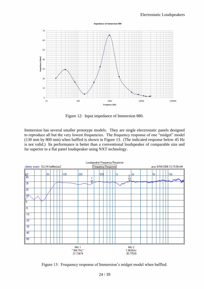
Immersion has several smaller prototype models. They are single electrostatic panels designed
to reproduce all but the very lowest frequencies. The frequency response of one “midget” model
(130 mm by 800 mm) when baffled is shown in Figure 13. (The indicated response below 45 Hz
is not valid.) Its performance is better than a conventional loudspeaker of comparable size and
far superior to a flat panel loudspeaker using NXT technology.
Figure 13: Frequency response of Immersion’s midget model when baffled.
Impedance of Immersion 880
0
10
20
30
40
50
60
70
10 100 1000 10000 100000
Frequency [Hz]
Imp
eda
nce
[o
hm
]

Electrostatic Loudspeakers
25 / 39
2.2 Listening Tests
Listening tests were performed in the same large listening room on all models. The room was
probably quite representative of a typical domestic environment and the reflections from various
objects in the room would have served to scatter the sound randomly throughout the room. The
loudspeakers were listened to at close range to better hear the direct sound and also further back
in the room to hear the direct and reflected sound together.
It was noted that the perceived frequency responses were quite similar to the measurements.
Distortion was not evident until amplifier overload was reached and then amplifier distortion was
heard rather than loudspeaker distortion. The writer was generally impressed by the clarity of
reproduction from all models but the perception of clarity was influenced by the frequency
response differences. It is the writer’s view that Immersion’s 880 model with its extended treble
response won the clarity tests.
When run in 5.1 channel mode, Immersion’s models performed exceptionally well and
comfortably achieved a realistically high SPL for movie presentations when supported by a high-
quality conventional subwoofer.

Electrostatic Loudspeakers
26 / 39
3. Market Potential
3.1 Short term market opportunities
A recent independent and comprehensive market appraisal on the loudspeaker industry has been
compiled under contract by Global Industry Analysts, Inc. [10]. The writer’s comments on the
market potential for Immersion’s electrostatic loudspeakers have drawn heavily upon this report.
The entire global loudspeaker market, including both electrostatic and magnetostatic
loudspeakers, was estimated to be worth around US$ 3,540 million in 2005 with an annual
growth rate of 3.0%. In the same year the total volume sales of loudspeakers was estimated to be
13.5 million units. On the other hand the sheer number of companies involved means each
company faces intense competition for a viable portion of the market.
Many loudspeaker companies, particularly the smaller ones, have resorted to finding specialised
niche markets. All companies have needed to be quick to respond to the changing demands of
customers, though ultimately what must influence customer preferences are the introduction by
companies of new products with improved technology, better performance and/or more pleasing
aesthetics. If new products are not readily accepted by customers through advertising and other
promotional methods then a loudspeaker company needs to adapt rapidly.
Above all, the music and entertainment industry is the major influence on the loudspeaker
industry. The introduction and ready availability of high-quality audio and video material
(including games and movies) on CDs, DVDs and the internet, together with the decreasing cost
of computers, players and amplifiers, has driven the demand for loudspeakers of better quality
yet more affordable and more pleasing aesthetically.
Recent significant marketing trends include
• Customer preference for surround sound systems instead of stereo systems
• Customer desire for louder, more powerful loudspeakers
• Customer desire for extended and louder bass response (subwoofers)
• Increasing importance of aesthetics, particularly the appeal of flat and thin structures
• Increasing emphasis on the size and placement of free-standing loudspeakers, particularly
wall placement off the floor
• Integrated video and audio panels for television, home theatre, computers, games, music
players and mobile phones
The most rapidly changing market is in home entertainment where there is now a convergence of
music, movies and games into one integrated entertainment platform combining television,
music and video players, games machines and personal computers into one arena.
Although many customers are not immediately influenced by the quality (frequency response,
distortion, clarity, etc.) of the sound reproduction from loudspeakers, it is the writer’s experience
that once customers have heard and listened at length to high-fidelity reproduction, as from
electrostatic panels, they learn to become more discerning of the quality they expect from
loudspeakers.

Electrostatic Loudspeakers
27 / 39
Immersion is planning to take up short-term (as well as long-term) market opportunities in the
home entertainment arena to which the electrostatic loudspeaker is entirely suited. A number of
surround sound packages are planned each of which will incorporate strip electrostatic panels of
various sizes together with conventional subwoofers. Larger panels will be used for the front left
and right loudspeakers, smaller ones for the rear left and right loudspeakers, and an intermediate-
sized horizontally-placed panel for the centre loudspeaker.
To give an idea of the world market potential for satellite/subwoofer loudspeaker systems,
Figure 14 below shows the recent past, current and future volume sales for both 3-piece and 6-
piece systems for the years 2000 to 2010 [10, Table 23].
Figure 14: World annual volume sales of satellite/subwoofer loudspeaker systems.
Immersion is also planning to license OEM electrostatic loudspeaker panel products for the
video panel market (plasma, LCD and others).
At this juncture it is important to emphasise the advantage of marketing conventional subwoofers
in pairs, not only for stereophonic (2 channel) systems but also for 5.1 and 7.1 channel systems
where the low-frequency effects (LFE or .1) channel is only monophonic. By the well-known
Small efficiency trade-off formula [9], the efficiency (the ratio of acoustical power out to the
electrical power in) of a conventional subwoofer is directly proportional to the total internal
enclosure volume BV [m3] for a given alignment and cut-off frequency. Thus the efficiency is
doubled either by doubling the volume of a single subwoofer or by using a second subwoofer of
the original size alongside the first subwoofer. However, the advantage of using a second
subwoofer is that the maximum input power handling capacity is also doubled, and the
combination of doubled efficiency and doubled input power means the maximum acoustical
output power is quadrupled (an increase of 6 dB in maximum SPL). But the perceived increase
in SPL is even greater than 6 dB because of the Fletcher-Munson curves [4, page 399] whereby
the human ear is insensitive to very low frequencies but once the SPL is above the threshold of
hearing the perceived loudness (in phons) increases more rapidly than the SPL (in dB) increases.
Furthermore, because the wavelengths at low frequencies are so large, it is possible to separate
Annual Volume Sales of Satellite/Subwoofer Loudspeakers
0
500,000
1,000,000
1,500,000
2,000,000
2,500,000
3,000,000
3,500,000
4,000,000
4,500,000
5,000,000
2000 2001 2002 2003 2004 2005 2006 2007 2008 2009 2010
3-piece loudspeakers 6-piece loudspeakers
total volume sales

Electrostatic Loudspeakers
28 / 39
the pair of subwoofers without losing the efficiency gain and place the individual subwoofers in
different locations in a room in order to minimise the effects of room modes (standing waves
between walls). Finally, there is probably a marketing advantage in selling two smaller
subwoofers that can be separated rather than one subwoofer of double the volume. Immersion is
wisely planning to incorporate conventional subwoofers in pairs into most of their packages.
3.2 Long term market potential
In the longer term Immersion has plans to penetrate the vast car entertainment market as well as
the games, video and music player market, including desk and portable models.
High-end products are also planned for the purist audiophile market where electrostatic
loudspeakers have traditionally enjoyed the best reputation. Immersion has already
demonstrated products that outperform some of the best commercially-available electrostatic
models.
One of the impending challenges to be faced by Immersion is the “SurfaceSound” technology
being marketed by NXT plc [13]. Their flat panel loudspeakers are essentially conventional
magnetostatic loudspeakers with a miniaturised permanent magnet and voice coil attached to a
reinforced flat panel instead of a conventional cone. In contrast to electrostatic panels, the force
applied to the diaphragm is concentrated near the centre resulting in break-up and resonances
that are difficult to control. Listening tests have confirmed that an (unbaffled) electrostatic panel
of similar size clearly outperforms a currently-marketed NXT panel (130 mm by 200 mm). (In
this size range both panels require a supplementary conventional subwoofer.)
The writer is completely confident that the future of the electrostatic loudspeaker, as continually
improved by Immersion, is assured. As more listeners worldwide come to appreciate the
inherent advantages in not only the cost but also the performance of electrostatic loudspeakers,
their uptake and acceptance in the marketplace will accelerate. The appeal of their thin structure
will further reinforce their popularity.

Electrostatic Loudspeakers
29 / 39
4. Conclusions
Immersion has succeeded in overcoming past limitations of electrostatic loudspeaker
construction and reliable mass production and is poised to challenge the conventional
magnetostatic loudspeaker in many areas of application, particularly the entertainment industry.
The challenge will take place on three fronts: the appeal of thin structures, cost competitiveness
and, last but not least, outstanding performance in comparable sizes.
This report has emphasised the sound theoretical and scientific basis for all of Immersion’s
claims.