Compensation for Measurement Errors Due to Mechanical Misalignments in PCB Testing Anura P....
24
Compensation for Measurement Errors Due to Mechanical Misalignments in PCB Testing Anura P. Jayasumana, Yashwant K. Malaiya, Xin He, Colorado State University Kenneth P. Parker and Stephen Hird Agilent Technologies
-
Upload
breana-sauvage -
Category
Documents
-
view
214 -
download
0
Transcript of Compensation for Measurement Errors Due to Mechanical Misalignments in PCB Testing Anura P....

Compensation for Measurement Errors Due to Mechanical
Misalignments in PCB Testing
Anura P. Jayasumana, Yashwant K. Malaiya, Xin He,
Colorado State University
Kenneth P. Parker and Stephen Hird
Agilent Technologies

Objective
2
• Identification of outlier boards using Capacitive Lead Frame Testing data
• Improve the accuracy of outlier detection by compensating for systematic errors such as mechanical misalignment and fixture-to-fixture variations
BTW 2010

Outline
PCA Based Outlier Detection Test Data for Mechanical Misalignments
PCA Based Compensation Summary
3BTW 2010

Capacitive Lead Frame Testing
4
SenseplateBuffer
Signal(to Tester)
PC board
Ball connections
In-Circuit access
Tester AC Source stimulates one pin, all others are grounded
Test access pad
Vacant Connector
(internal conductors)
Ref: Parker & Hird, ITC 2007 BTW 2010

Example: Capacitance vs. Pin Number (for a J245)
5BTW 2010

6
1st Principal Component contains largest variance from the data projection
2nd Principal Component, orthogonal to the 1st one, contains second largest projected variance
Useful for analyzing multi-dimensional interrelated data
Mea
sure
men
t 2
2nd PC
1st PC
0Measurement 1
Principal Component Analysis (PCA)
BTW 2010

PCA for PCB Outlier DetectionSingular Value Decomposition
Mc = USVT
where,
Umxn A scaled version of PC scores
Snxn Diagonal matrix with square roots of Eigen values in descending order
VTnxn Eigen vectors (PCs).
V Transformation Matrix
Z = McV Matrix with z-score values of boards
Z-scores of a board are linear combination of all corresponding measurements for that board 8BTW 2010

Test Statistic for Outlier Detection
9
Ek
iki zd 21
zik : Value of the kth PC for ith board
E : a subset of PCs - most significant PCs are used here
Sort the boards with respect to d1
Plot cumulative distribution function (CDF) of d1
Outliers clearly identifiable on right side of plot, typically separated from others by a clear margin
BTW 2010

10
Board run numbers on CDF plot from left to right: 52,51,50,53,49,32,73,24,48,25,74,72,83,71,57,47,1,42,56,70,6,68,38,37,58,43,59,41,39,55,40,2,23,78,33,35,44,69,79,54,75,36,64,80,76,31,77,65,60,29,81,63,61,62,3,67,66,82,27,45,28,46,26,30,34,12,8,7,10,9,16,11,13,14,15,4,5,17,22,19,18,20,21
PCA Based Outlier Detection
ITC 2009
• Treats data holistically• Outlier detection as
opposed to threshold based detection

Capacitive Lead Frame Testing
11
SenseplateBuffer
Signal(to Tester)
PC board
Ball connections
In-Circuit access
Tester AC Source stimulates one pin, all others are grounded
Test access pad
Vacant Connector
(internal conductors)
Ref: Parker & Hird, ITC 2007
• Capacitance < 100fF (<10fF with opens faults) • Systematic variations, e.g., variations in connector height,
co-planarity of ball connections, sense plate, … • Relatively small mechanical variations can lead to larger
measurement variability(Ex. 18fF variation across shift test cases vs. std deviation of <1fF)
• Test values and test limits set now may fail if mechanical variations appear later
BTW 2010

Mechanical Misalignments
12
Vacant Connector
Senseplate
Buffer
Spacers placed between plate and connector at one end. Again, the spacers have a different dielectric constant from air.
Vacant Connector
SenseplateBuffer
Spacers placed between plate and connector. Most connector pin tips see an air gap to the sense plate, but at the ends, the gap has a different dielectric constant.
Setup Left or right End Tilt Height (mils) Setup Vertical Shift
Height (mils)
Tilt_0 0 Shift_0 0
Tilt_1 8 Shift _1 8
Tilt_2 16 Shift_2 16
Tilt_3 24 Shift_3 24
BTW 2010

Raw measurements for B1 with one normal and three left tilted sense plates
35
55
75
95
115
Mea
sure
d C
apac
itan
ce (
fF)
Pin Number
Tilt_0
Tilt_1
Tilt_2
Tilt_3
BTW 2010

Raw measurements with normal and verticalshifted sense plate for board B5 connector J3
45
65
85
105
125
145
Mea
sure
d C
apac
itan
ce
(fF
)
Pin Number
Shift_0
Shift_1
Shift_2Shift_3
BTW 2010
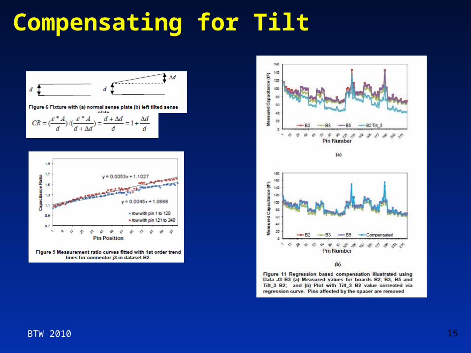
Compensating for Tilt
15BTW 2010

Raw measurements with normal and verticalshifted sense plate for board B5 connector J3
45
65
85
105
125
145
Mea
sure
d C
apac
itan
ce
(fF
)
Pin Number
Shift_0
Shift_1
Shift_2Shift_3
BTW 2010

Plot of PC values for Shift Data
Note:• PC-1 can be used to identify the amount of shift or tilt in sense plate• Unlike visual inspection, PCA can identify complex but systematic
patterns• If the same board is tested in multiple fixtures, it may be possible
to identify differences and compensate for themBTW 2010

Adjusted capacitances by setting all but 1st PCequal to 0 for data B1
• PC-1 captures the tilt information as well as other common information
BTW 2010

Data set including two synthetic traces, Def_1 and Def_2 simulating open faults on pins 121 and 165
BTW 2010

Adjusted capacitances by setting only 1st PCs to 0
BTW 2010

Data set including two synthetic traces, Def_1 and Def_2 simulating open faults on pins 75 and 165
BTW 2010

Adjusted capacitance by setting all but 1st PC to zero
BTW 2010

Adjusted data based on setting only 1st PC to 0
BTW 2010

24
A PCA based technique presented for identification and compensation for measurement errors introduced due to sense-plate variations
Method can be used to separate misalignment related information from defect related information in test data
Approach is NOT sensitive to the order of the pins, and thus shows promise for complex but systematic errors introduced by sense plate misalignments
Method applicable to other kinds of test data
Summary
BTW 2010

25
Overcome variations caused by measurement errors, mechanical and electrical tolerances
Adaptive and learning techniques for detection and diagnosis
Future Work
BTW 2010