Comparative study of RCC and Steel-Concrete composite ...
10
Proceedings of IOE Graduate Conference, 2019-Summer Peer Reviewed Year: 2019 Month: May Volume: 6 ISSN: 2350-8914 (Online), 2350-8906 (Print) Comparative study of RCC and Steel-Concrete composite structure under Time history Analysis Keshab Singh Badal a , Hari Darshan Shrestha b a, b Department of Civil Engineering, Pulchowk Campus, IOE, Tribhuvan University, Nepal Corresponding Email: a [email protected], b [email protected] Abstract In Nepal, generally traditional RCC framed structure are preferred due to its familiarity. However, these structures are considered more suitable for the low rise building only and not suitable for the high-rise building due to its higher weight, restriction to maximum span, requirement of formwork and other reasons. During the “25th April 2015 Gorkha earthquake”, it was observed that most of the high-rise building and apartments were highly affected. So for new construction of high-rise building and apartments, steel-concrete composite can be used to replace the traditional RCC section because of their excellent strength, ductility, better economy, better energy absorption capacity and performance during earthquake. Steel-concrete composite elements are widely used in the construction of building, bridges, offshore structure and other structures worldwide, however it is new concept for the construction industry in Nepal. A composite column is built by encasing the steel member by concrete or simply steel section is embedded in concrete section. This thesis work presents the comparative study of performance of building with RCC and steel-concrete structural system. It has been found that, steel-concrete composite structures will be relatively lighter, flexible with higher time periods and attracts considerably lesser horizontal seismic forces. Hence, construction with steel-concrete composite was found to be useful for the location with high seismicity like Nepal. Keywords Composite Structure, RCC Structure, Composite Column, Steel Beam, Shear Connector, time history analysis, ETAB software 1. Introduction In Nepal reinforced concrete members are mostly used in the framing system for most of the building since this is the most convenient and economical system for low-rise buildings. However, there is need of vertical growth of building due to lack of land space and increase in population in urban area, so medium to high-rise building are becoming necessary for recent and upcoming scenario. For this composite construction gained several advantages in comparison to the conventional system construction. It is all because, for medium to high-rise building this RCC structures are no longer economic because of increased dead load, less stiffness, span restriction and hazardous formwork [1] . Steel concrete composite frame system can provide an effective and economic solution to most of these problems in medium to high-rise building. Moment resisting RCC structures are very common in Nepal for building construction. With time, the requirements for construction of high-rise buildings have increased with a challenge to resist high seismic loads. Hence, an economical construction technology with better structural performance has been investigated. Structural members that are made up of two or more different materials are known as composite elements. Composite structure are more flexible than the RCC structure. The deformation of the structure is classified into three categories as overall building movements, story drift and other internal deformation and inelastic deformation for structural component and elements. These movements occurs due to rigid body displacement and shear deformations [2]. The main benefit of the composite elements that is the properties of each material can be combined to form a unit that perform better overall than its separate constituent parts. There are many type of composite elements like steel-timber, timber-concrete, plastic-concrete etc. but most common form of Pages: 29 – 38
Transcript of Comparative study of RCC and Steel-Concrete composite ...

Proceedings of IOE Graduate Conference, 2019-SummerPeer Reviewed
Year: 2019 Month: May Volume: 6ISSN: 2350-8914 (Online), 2350-8906 (Print)
Comparative study of RCC and Steel-Concrete compositestructure under Time history Analysis
Keshab Singh Badal a, Hari Darshan Shrestha b
a, b Department of Civil Engineering, Pulchowk Campus, IOE, Tribhuvan University, NepalCorresponding Email: a [email protected], b [email protected]
AbstractIn Nepal, generally traditional RCC framed structure are preferred due to its familiarity. However, thesestructures are considered more suitable for the low rise building only and not suitable for the high-rise buildingdue to its higher weight, restriction to maximum span, requirement of formwork and other reasons. During the“25th April 2015 Gorkha earthquake”, it was observed that most of the high-rise building and apartments werehighly affected. So for new construction of high-rise building and apartments, steel-concrete composite canbe used to replace the traditional RCC section because of their excellent strength, ductility, better economy,better energy absorption capacity and performance during earthquake. Steel-concrete composite elementsare widely used in the construction of building, bridges, offshore structure and other structures worldwide,however it is new concept for the construction industry in Nepal. A composite column is built by encasing thesteel member by concrete or simply steel section is embedded in concrete section. This thesis work presentsthe comparative study of performance of building with RCC and steel-concrete structural system. It has beenfound that, steel-concrete composite structures will be relatively lighter, flexible with higher time periods andattracts considerably lesser horizontal seismic forces. Hence, construction with steel-concrete composite wasfound to be useful for the location with high seismicity like Nepal.
KeywordsComposite Structure, RCC Structure, Composite Column, Steel Beam, Shear Connector, time history analysis,ETAB software
1. Introduction
In Nepal reinforced concrete members are mostlyused in the framing system for most of the buildingsince this is the most convenient and economicalsystem for low-rise buildings. However, there is needof vertical growth of building due to lack of landspace and increase in population in urban area, somedium to high-rise building are becoming necessaryfor recent and upcoming scenario. For this compositeconstruction gained several advantages in comparisonto the conventional system construction. It is allbecause, for medium to high-rise building this RCCstructures are no longer economic because ofincreased dead load, less stiffness, span restriction andhazardous formwork [1] . Steel concrete compositeframe system can provide an effective and economicsolution to most of these problems in medium tohigh-rise building. Moment resisting RCC structuresare very common in Nepal for building construction.
With time, the requirements for construction ofhigh-rise buildings have increased with a challenge toresist high seismic loads. Hence, an economicalconstruction technology with better structuralperformance has been investigated.
Structural members that are made up of two or moredifferent materials are known as composite elements.Composite structure are more flexible than the RCCstructure. The deformation of the structure isclassified into three categories as overall buildingmovements, story drift and other internal deformationand inelastic deformation for structural componentand elements. These movements occurs due to rigidbody displacement and shear deformations [2]. Themain benefit of the composite elements that is theproperties of each material can be combined to form aunit that perform better overall than its separateconstituent parts. There are many type of compositeelements like steel-timber, timber-concrete,plastic-concrete etc. but most common form of
Pages: 29 – 38

Comparative study of RCC and Steel-Concrete composite structure under Time history Analysis
composite element in construction is a steel-concretecomposite.
The steel and concrete are compatible andcomplementary to each other as steel is good intension and concrete is good in compression and theyhave almost same thermal expansion coefficient. Inaddition, concrete cover and/or filler prevents theoccurrence of local buckling; in turn, steel hollowsection enhances the concrete confinement and fireand corrosion resistance [3]. The benefits ofcomposite construction include speed of construction,performance and value. Steel framing for a structurecan be erected quickly and the pre-fabricated steelfloor decks can be put in place immediately. Whencured, the concrete provides additional stiffness to thestructure. Additionally, the concrete encasementprotects the steel from buckling, corrosion and fire.Service integration within the channels on thecomposite decks is another advantage to compositeconstruction. In the composite structure, the concreteact together with the steel to create a stiffer, lighter,less expensive structure. Material handling at site isless and has better ductility, hence superior lateralload behavior; better earthquake resistance. Inaddition, it has ability to cover large column free areain buildings.
1.1 Composite beam and slab
If the steel beams are connected to the concrete slab insuch a way that they two act as single unit, the beamis called as composite beam. A composite beamconsists of a steel beam, over which a reinforcedconcrete slab is cast. The composite interaction isachieved by the attachment of shear connectors to thetop flange of the beam. The composite action reducesthe overall beam depth by the effective compositeaction between steel beam and concrete slab. Theprincipal merit of steel-concrete compositeconstruction lies in the utilization of the compressivestrength of concrete slabs in conjunction with steelbeams, in order to enhance the strength and stiffnessof the steel beam [4].
1.2 Composite Column
It is conventionally a compression membercomprising either a concrete encased hot-rolled steelsection or a concrete filled tabular steel section.Concrete filled steel tube (CFST) construction arelighter compared to RCC structure [5]. In composite
column both steel and concrete, resist the loading byinteracting together by bond and friction. Theinteractive and integral property of steel and concretemakes the composite column very stiff, more ductile,cost effective and structurally efficient member. Thelighter weight and higher strength of steel permit theuse of smaller section and light foundation andaddition of concrete enables the structure to easilylimit the sway and lateral deflections.
1.3 Shear Connectors
In order that the steel beam and slab act as acomposite structure, the connectors must haveadequate strength and stiffness. If there are nohorizontal or vertical separations at the interface, theconnectors are described as rigid; completeinteraction can be said to exist under these idealizedcircumstances. However, all connectors are flexible tosome extent, and therefore partial interaction alwaysexists. For most connectors used in practice, failureby vertical separation is unlikely and any uplift wouldhave only negligible effect on the behavior of thecomposite structure.
Various composite structure elements[6] are shownbelow:-
Figure 1: Composite Structure elememts
2. Objectives and Scope of Study
• To investigate major parameter likefundamental time period, storey drift, lateraljoint displacements, bending moments andshear force in column.
• To find out best suited range for compositeconstruction.
• To check the effectiveness of shear wall in RCC
30

Proceedings of IOE Graduate Conference, 2019-Summer
versus composite Structure.
The scope of the present study aims at compare theperformance of G+5, G+8, G+11, G+15,G+20, G+30RCC and composite building frame situated inearthquake zone V. All frames are designed for samegravity loadings. RC frame designed as usual andsteel concrete composite structure designed as steelsection encased in concrete for columns and theconcrete slab is connected to steel beam with the helpof mechanical shear connectors so that they act assingle unit. Time History method is used for seismicanalysis. E-tab16 is use and results are compare forboth of the cases for all stories building.
3. Methodology
Analysis of the building has been carried out by usingETAB 16.2. Here, the synthetic time history has beengenerated using three earthquakes namely Darfield(New Zealand), Imperial Valley (California, USA)and Kobe earthquake (Japan) with target spectrumtaken as response spectrum given for the medium soilas per IS code 1893:2002. Here, the peak inputacceleration of the Darfield, Imperial and Kobeearthquake before matching was 0.22g for time periodof 5.667 sec, 0.26g for time period of 0.433 sec and0.203g for time period of 3.04 sec whereas aftermatching the accelerograms with the target spectrumthe peak input was found to be 0.38g for 5.655 sec,0.40g for 1.03 sec and 0.38g for time period of 3.288sec respectively. For response evaluation of allstructures, selecting the best earthquake wave whichgives maximum response by using linear time historyanalysis.
Figure 2: Displacements in x-direction due to variousearthquake force in G+8 RCC
Step-wise procedure has been discussed below :
1. Based upon the literature review and generalpractice 20m x 12m plan is selected as buildingplan. Six models G+5, G+8, G+11, G+15,G+ 20 and G+ 30 story are created for bothRCC and steel-concrete composite on the sameplan.
2. Size of the members is selected as they meetboth strength and serviceability criteria.
3. Define load pattern like a dead load, live load,Super dead load, EQx, EQy etc. and assign tothe frame objects.
4. Based upon the model analysis, check whethermembers will passed or not strength andserviceability limit, if passed its ok otherwiserepeat member size selection and analyze again.
5. Since the analysis of the RCC and compositebuilding are to be formulated using theminimum of three earthquakes based upon theFEMA, firstly the three earthquakes data whichare closed to the target response spectrum basedupon the IS 1893:2002 was obtained from thePeer Barkley NGA west database site. Basedupon the above procedure the three majorearthquakes which are closer to the targetresponse spectrum was found to be Kobeearthquake (Japan), Imperial Valley earthquake(California, US) and Darfield (New Zealand)respectively.
6. Define the target response spectrum functionbased upon the IS 1893:2002 from Defineoptions.
7. Define the time history function of the respectiveearthquake by going to define > time historyfunction> choose function type as from file >make necessary arrangement based upon theobtained notepad data obtained from the PeerBarkley.
8. Matching of the practical earthquake responsewith the target response spectrum as define >time history function > function type >matched to response spectrum. Here thematching has been carried out based upon thespectral matching with time domain type. Asper ASCE 7-10, the target response spectrumwas considered to matched with the referenceacceleration time history if the match range is
31

Comparative study of RCC and Steel-Concrete composite structure under Time history Analysis
within 0.2T to 1.5T where, T is the fundamentaltime period in seconds.
9. Define the static load case and set analysis typeas time history > linear model.
10. Since the linear analysis is under the action noconsideration of the geometric and material non-linearity is carried out i.e. no consideration ofthe hinge and P-delta effect.
11. Arrange the load case type to acceleration >load name as U1 and U2 > function as thematched time history type for the respectiveearthquakes > scale factor is considered as(IG/R) of EQx or EQy in case if the base shearof THx and THy are less than (IG/R) of EQxand EQy.
12. Analysis of the maximum responses regard tothe both RCC and Composite buildings regardto the responses such as top displacement, interstory drift, base shear and overturning momenthas been carried out.
13. The maximum responses of RCC andComposite building will then be compared witheach other and check with the variation in thecode limit if any.
Figure 3: Response spectrum of original, matchedand target spectrum for Imperial earthquake
Figure 4: Synthetic time history of Imperial ValleyEQ
4. Model Configuration
32

Proceedings of IOE Graduate Conference, 2019-Summer
Figure 5: 3D view G+8 Model
Figure 6: Plan area for all models
4.1 Material Properties
Concrete properties:[7]
• Characteristic strength of concrete(fck)=30Mpaand 25Mpa
• Modulus of elasticity (Ec)=5000 sqrt fck Mpa• Density of concrete = 25 KN/m3• Poisson’s Ratio (u) = 0.2
Reinforcement properties:
• Minimum Yield Strength(Fy)= 500 MPa• Modulus of elasticity (Es)=200,000 Mpa• Density of steel = 7850 KN/m3• Poisson’s Ratio (u) = 0.3
Steel properties:[8]
• Minimum Yield Strength(Fy)= 250 MPa• Modulus of elasticity (Es)=210,000 Mpa• Density of steel = 7850 KN/m3• Poisson’s Ratio (u) = 0.3
4.2 Seismic Parameter: [9]
• Zone factor, Z = 0.36 (Zone V)• Importance Factor I = 1.0• Response Reduction factor, R = 5• Soil type = Medium Soil• Damping Coefficient = 0.05
5. Result and Discussion
5.1 Dead Load
Figure 7: Dead load comparison between RCC andcomposite
33

Comparative study of RCC and Steel-Concrete composite structure under Time history Analysis
5.2 Time Period
Figure 8: Time period
5.3 Base shear
Figure 9: Base Shear comparison between RCC andcomposite
Figure 10: percentage of Base shear variation
5.4 Max. Story displacement
Figure 11: Max Displacements of buildings
Figure 12: percentage of displacement variation
34

Proceedings of IOE Graduate Conference, 2019-Summer
5.5 Max. Story drift
Figure 13: Max Drift of buildings
Figure 14: percentage of drift variation
5.6 Overturning Moment
Figure 15: Overturning Moment of various buildings
Figure 16: percentage of overturning momentvariation
5.7 Axial Force in Column
Figure 17: Axial force in columns
35
Comparative study of RCC and Steel-Concrete composite structure under Time history Analysis
Figure 18: percentage of Axial force variation
5.8 Shear Force in Column
Figure 19: Axial force in columns
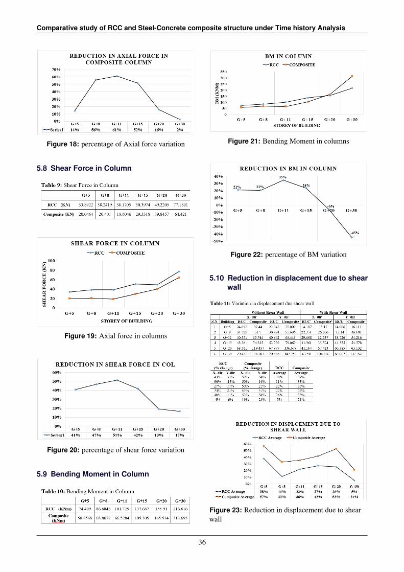
Figure 20: percentage of shear force variation
5.9 Bending Moment in Column
Figure 21: Bending Moment in columns
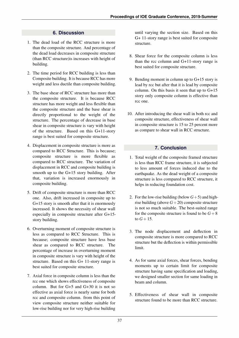
Figure 22: percentage of BM variation
5.10 Reduction in displacement due to shearwall
Figure 23: Reduction in displacement due to shearwall
36
Proceedings of IOE Graduate Conference, 2019-Summer
6. Discussion
1. The dead load of the RCC structure is morethan the composite structure. And percentage ofthe dead load decreases in composite structure(than RCC structure)is increases with height ofbuilding.
2. The time period for RCC building is less thanComposite building. It is because RCC has moreweight and less ductile than composite building.
3. The base shear of RCC structure has more thanthe composite structure. It is because RCCstructure has more weight and less flexible thanthe composite structure and the base shear isdirectly proportional to the weight of thestructure. The percentage of decrease in baseshear in composite structure is vary with heightof the structure. Based on this G+11-storyrange is best suited for composite structure.
4. Displacement in composite structure is more ascompared to RCC Structure. This is because;composite structure is more flexible ascompared to RCC structure. The variation ofdisplacement in RCC and composite building issmooth up to the G+15 story building. Afterthat, variation is increased enormously incomposite building.
5. Drift of composite structure is more than RCCone. Also, drift increased in composite up toG+15 story is smooth after that it is enormouslyincreased. It shows the necessity of shear wallespecially in composite structure after G+15-story building.
6. Overturning moment of composite structure isless as compared to RCC Structure. This isbecause; composite structure have less baseshear as compared to RCC structure. Thepercentage of increase in overturning momentin composite structure is vary with height of thestructure. Based on this G+ 11-story range isbest suited for composite structure.
7. Axial force in composite column is less than thercc one which shows effectiveness of compositecolumn. But for G+5 and G+30 it is not soeffective as axial force is nearly same for bothrcc and composite column. from this point ofview composite structure neither suitable forlow-rise building nor for very high-rise building
until varying the section size. Based on thisG+ 11-story range is best suited for compositestructure.
8. Shear force for the composite column is lessthan the rcc column and G+11-story range isbest suited for composite structure.
9. Bending moment in column up to G+15 story islead by rcc but after that it is lead by compositecolumn. On this basis it seen that up to G+15story only composite column is effective thanrcc one.
10. After introducing the shear wall in both rcc andcomposite structure, effectiveness of shear wallin composite structure is 15 to 25 percent moreas compare to shear wall in RCC structure.
7. Conclusion
1. Total weight of the composite framed structureis less than RCC frame structure, it is subjectedto less amount of forces induced due to theearthquake. As the dead weight of a compositestructure is less compared to RCC structure, ithelps in reducing foundation cost.
2. For the low-rise building (below G+5) and high-rise building (above G+20) composite structureis not so much suitable. The best-suited rangefor the composite structure is found to be G+8to G+15.
3. The node displacement and deflection incomposite structure is more compared to RCCstructure but the deflection is within permissiblelimit.
4. As for same axial forces, shear forces, bendingmoments up to certain limit for compositestructure having same specification and loading,we designed smaller section for same loading inbeam and column.
5. Effectiveness of shear wall in compositestructure found to be more than RCC structure.
37

Comparative study of RCC and Steel-Concrete composite structure under Time history Analysis
References
[1] Shashikala Koppad and Dr S V Itti. Comparative studyof RCC and composite multistoreyed buildings. 3(5):5.
[2] D R Panchal and P M Marathe. Comparative studyof r.c.c, steel and composite (g+30 storey) building.page 6.
[3] Edoardo Cosenza, Luigi Di Sarno, GiovanniFabbrocino, and Marisa Pecce. Composite steel andconcrete structures: Technology and design. page 11.
[4] Rakesh Abrol, Dr SK Kulkarni, and Vishwajeet Kadlag.Seismic analysis of RCC and composite structures.page 9.
[5] Raghabendra Yadav, Baochun Chen, Yuan Huihui,
and Rabindra Adhikari. Comparative analysis ofreinforced concrete buildings and concrete filled steeltube buildings in nepal. page 9.
[6] Mahbuba Begum and Serajus Salekin. COSTANALYSIS OF STEEL CONCRETE COMPOSITESTRUCTURES IN BANGLADESH. page 10.
[7] Indian Standard BIS. IS 456: Code of practice for plainand reinforced concrete.
[8] Bureau Indian Standard. General construction in steel-code of practice. pages 800–2007.
[9] Indian Standard. Criteria for earthquake resistantdesign of structures. 1.
38