Comparative Study and Analysis of Unbraced RCC Framed ...
15
Comparative Study and Analysis of Unbraced RCC Framed Structure with Steel Braced RCC Framed Structure using Response Spectrum Method Jonty Choudhary 1 , 1 Student, M. Tech (Structural Engineering) GEC Jagdalpur (C.G.) Dr. G. P. Khare 2 2 Principal & Professor, GEC Jagdalpur (C.G.) Abstract- Lateral forces induced on the structure due to seismic waves have given rise to the study of lateral load resisting elements such as braces, shear wall, dampers etc. These lateral load resisting elements should be analysed before arriving on a best orientation and configuration. This work is an analysis of braces and there orientation, configuration and arriving on a best bracing system. In this project there is a comparison of unbraced RCC framed structure and steel Braced RCC framed structure the steel braces are of different configurations such as X, V, inverted V and their different arrangements have been studied, analysed using ETABS 2015 and results are compared. For the analysis a Special Moment Resisting Frame of G+15 Storey is modelled in ETABS 2015 which is 33m×15m. The objective is to have a comparative perspective of unbraced and steel braced RCC frame, all the frames are subjected to same DL, IL and Earthquake loads all the structure are in the same earthquake zone i.e.; Zone V. It is found that when X-braced RCC frame structure performed best when compared with the parameters of Maximum Storey Displacement, Maximum Storey Drift, Base Shear, Overturning moments and Time period of unbraced RCC frame structure. With the use of X-braced steel bracings the structure can be designed using lighter section and thus economic efficiency can be achieved. High construction quality should be maintained while embedding steel bracing at beam-column joints. IS 13920 (1993): Ductile detailing of reinforced concrete structures subjected to seismic forces – Code of practice should be preferred and the codal provisions should be achieved as far as possible. Key words- Maximum storey displacement, Maximum storey drift, Base shear, Resisting moments, Time period, ETABS, RCC. 1. INTRODUCTION Earthquake can be understood as the shaking of earth’s crust which can be due to relative movement in tectonic plates, volcano eruptions and even in case of explosions. There can be huge loss of life as experienced in past earthquakes in India and the world. Apart from loss of life there is economic loss also. Industrialization has given rise to many things one of which is high rise buildings. High rise building requires in depth analysis of response of the building for a given set of load conditions. In general structure is designed for gravity loads, imposed loads, wind loads, snow loads and earthquake loads. Earthquake loads have a different tendency as compared to other loads, these loads induces lateral forces on to the structure. Lateral force induces forces parallel to the plane of the structure this has given rise to study of lateral force resisting elements such as shear wall, dampers, bracings etc. Steel which have good compressive and tensile load carrying property are used as braces. Depending upon the configuration steel braces can be classified as concentric and eccentric. Concentric braces such as X, V, inverted V are used. In the previous works many such bracing configurations have been studied. This work aims at studying the response of G+15 storied special moment resisting RCC framed structure subjected to earthquake excitation in seismic Zone V( as per IS 1893: (Part 1) 2002). X, V and inverted V braces are used in different arrangements (shown in modelling). All the models are in same seismic zone with same structural properties. 2. OBJECTIVES OF PRESENT STUDY The objective of this work is to know the response of a G+15 storey unbraced RCC framed structure in comparison to concentrically steel braced G+15 storey RCC framed structure with different arrangements of steel bracing. To have an insight in the performance of these steel braced RCC framed structure linear dynamic analysis is performed i.e.; Response Spectrum Analysis. Following are the aspects which are attempted to study: I. Comparison of storey displacement for G+15 storied unbraced RCC framed structure and concentrically steel braced G+15 RCC framed structure. II. Comparison of storey drift for G+15 storied unbraced RCC framed structure and concentrically steel braced G+15 RCC framed structure. III. Comparison of base shear for G+15 storied unbraced RCC framed structure and concentrically steel braced G+15 RCC framed structure. IV. Comparison of base reaction for G+15 storied unbraced RCC framed structure and concentrically steel braced G+15 RCC framed structure. V. Comparison of time period for G+15 storied unbraced RCC framed structure and concentrically steel braced G+15 RCC framed structure. 3. MODELLING The structure which is considered in this project work have been analysed in ETABS 2015. A G+15 storied structure is considered for the analysis using Response Spectrum Method. The structure is 33×15 m in plan. Columns are placed in 3m interval in both X and Y direction. The structure lies in earthquake zone V and has a importance International Journal of Engineering Research & Technology (IJERT) ISSN: 2278-0181 http://www.ijert.org IJERTV7IS080045 (This work is licensed under a Creative Commons Attribution 4.0 International License.) Published by : www.ijert.org Vol. 7 Issue 08, August-2018 120
Transcript of Comparative Study and Analysis of Unbraced RCC Framed ...

Comparative Study and Analysis of Unbraced RCC Framed Structure with Steel Braced RCC
Framed Structure using Response Spectrum Method
Jonty Choudhary1,
1Student, M. Tech (Structural Engineering)
GEC Jagdalpur (C.G.)
Dr. G. P. Khare2 2 Principal & Professor, GEC Jagdalpur (C.G.)
Abstract- Lateral forces induced on the structure due to seismic waves have given rise to the study of lateral load resisting elements such as braces, shear wall, dampers etc. These lateral load resisting elements should be analysed before arriving on a best orientation and configuration. This work is an analysis of braces and there orientation, configuration and arriving on a best bracing system. In this project there is a comparison of unbraced RCC framed structure and steel Braced RCC framed structure the steel braces are of different configurations such as X, V, inverted V and their different arrangements have been studied, analysed using ETABS 2015 and results are compared. For the analysis a Special Moment Resisting Frame of G+15 Storey is modelled in ETABS 2015 which is 33m×15m. The objective is to have a comparative perspective of unbraced and steel braced RCC frame, all the frames are subjected to same DL, IL and Earthquake loads all the structure are in the same earthquake zone i.e.; Zone V. It is found that when X-braced RCC frame structure performed best when compared with the parameters of Maximum Storey Displacement, Maximum Storey Drift, Base Shear, Overturning moments and Time period of unbraced RCC frame structure. With the use of X-braced steel bracings the structure can be designed using lighter section and thus economic efficiency can be achieved. High construction quality should be maintained while embedding steel bracing at beam-column joints. IS 13920 (1993): Ductile detailing of reinforced concrete structures subjected to seismic forces – Code of practice should be preferred and the codal provisions should be achieved as far as possible. Key words- Maximum storey displacement, Maximum storey drift, Base shear, Resisting moments, Time period, ETABS, RCC.
1. INTRODUCTION Earthquake can be understood as the shaking of
earth’s crust which can be due to relative movement in tectonic plates, volcano eruptions and even in case of explosions. There can be huge loss of life as experienced in past earthquakes in India and the world. Apart from loss of life there is economic loss also. Industrialization has given rise to many things one of which is high rise buildings. High rise building requires in depth analysis of response of the building for a given set of load conditions. In general structure is designed for gravity loads, imposed loads, wind loads, snow loads and earthquake loads. Earthquake loads have a different tendency as compared to other loads, these loads induces lateral forces on to the structure. Lateral force induces forces parallel to the plane of the structure this has given rise to study of lateral force resisting elements such as shear wall, dampers, bracings etc. Steel which have good compressive and tensile load carrying property are used as braces. Depending upon the configuration steel braces can
be classified as concentric and eccentric. Concentric braces such as X, V, inverted V are used.
In the previous works many such bracing configurations have been studied. This work aims at studying the response of G+15 storied special moment resisting RCC framed structure subjected to earthquake excitation in seismic Zone V( as per IS 1893: (Part 1) 2002). X, V and inverted V braces are used in different arrangements (shown in modelling). All the models are in same seismic zone with same structural properties.
2. OBJECTIVES OF PRESENT STUDY The objective of this work is to know the response
of a G+15 storey unbraced RCC framed structure in comparison to concentrically steel braced G+15 storey RCC framed structure with different arrangements of steel bracing. To have an insight in the performance of these steel braced RCC framed structure linear dynamic analysis is performed i.e.; Response Spectrum Analysis. Following are the aspects which are attempted to study:
I. Comparison of storey displacement for G+15 storied unbraced RCC framed structure and concentrically steel braced G+15 RCC framed structure.
II. Comparison of storey drift for G+15 storied unbraced RCC framed structure and concentrically steel braced G+15 RCC framed structure.
III. Comparison of base shear for G+15 storied unbraced RCC framed structure and concentrically steel braced G+15 RCC framed structure.
IV. Comparison of base reaction for G+15 storied unbraced RCC framed structure and concentrically steel braced G+15 RCC framed structure.
V. Comparison of time period for G+15 storied unbraced RCC framed structure and concentrically steel braced G+15 RCC framed structure.
3. MODELLING The structure which is considered in this project work have been analysed in ETABS 2015. A G+15 storied structure is considered for the analysis using Response Spectrum Method. The structure is 33×15 m in plan. Columns are placed in 3m interval in both X and Y direction. The structure lies in earthquake zone V and has a importance
International Journal of Engineering Research & Technology (IJERT)
ISSN: 2278-0181http://www.ijert.org
IJERTV7IS080045(This work is licensed under a Creative Commons Attribution 4.0 International License.)
Published by :
www.ijert.org
Vol. 7 Issue 08, August-2018
120
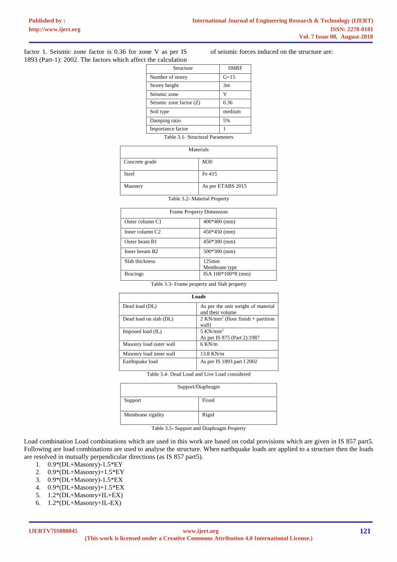
factor 1. Seismic zone factor is 0.36 for zone V as per IS 1893 (Part-1): 2002. The factors which affect the calculation
of seismic forces induced on the structure are:
Structure SMRF
Number of storey G+15 Storey height 3m
Seismic zone V Seismic zone factor (Z) 0.36
Soil type medium
Damping ratio 5% Importance factor 1
Table 3.1- Structural Parameters
Materials
Concrete grade M30
Steel Fe 415
Masonry As per ETABS 2015
Table 3.2- Material Property
Frame Property Dimension
Outer column C1 400*400 (mm)
Inner column C2 450*450 (mm)
Outer beam B1 450*300 (mm)
Inner bream B2 500*300 (mm)
Slab thickness 125mm Membrane type
Bracings ISA 100*100*8 (mm)
Table 3.3- Frame property and Slab property
Loads
Dead load (DL) As per the unit weight of material and their volume
Dead load on slab (DL) 2 KN/mm2 (floor finish + partition wall)
Imposed load (IL) 5 KN/mm2 As per IS 875 (Part 2):1987
Masonry load outer wall 6 KN/m
Masonry load inner wall 13.8 KN/m Earthquake load As per IS 1893 part I 2002
Table 3.4- Dead Load and Live Load considered
Support/Diaphragm
Support Fixed
Membrane rigidity Rigid
Table 3.5- Support and Diaphragm Property
Load combination Load combinations which are used in this work are based on codal provisions which are given in IS 857 part5. Following are load combinations are used to analyse the structure. When earthquake loads are applied to a structure then the loads are resolved in mutually perpendicular directions (as IS 857 part5).
1. 0.9*(DL+Masonry)-1.5*EY 2. 0.9*(DL+Masonry)+1.5*EY 3. 0.9*(DL+Masonry)-1.5*EX 4. 0.9*(DL+Masonry)+1.5*EX 5. 1.2*(DL+Masonry+IL+EX) 6. 1.2*(DL+Masonry+IL-EX)
International Journal of Engineering Research & Technology (IJERT)
ISSN: 2278-0181http://www.ijert.org
IJERTV7IS080045(This work is licensed under a Creative Commons Attribution 4.0 International License.)
Published by :
www.ijert.org
Vol. 7 Issue 08, August-2018
121
7. 1.2*(DL+Masonry+IL+EY) 8. 1.2*(DL+Masonry+IL-EY) 9. 1.5*(DL+Masonry+EX) 10. 1.5*(DL+Masonry+EY) 11. 1.5*(DL+Masonry+IL) 12. 1.5*(DL+Masonry-EX) 13. 1.5*(DL+Masonry-EY
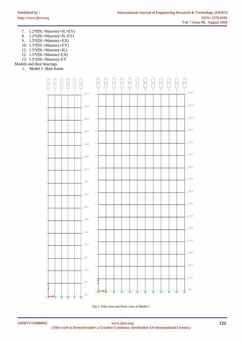
Models and their bracings 1. Model 1 -Bare frame
Fig 1- Side view and Front view of Model 1
International Journal of Engineering Research & Technology (IJERT)
ISSN: 2278-0181http://www.ijert.org
IJERTV7IS080045(This work is licensed under a Creative Commons Attribution 4.0 International License.)
Published by :
www.ijert.org
Vol. 7 Issue 08, August-2018
122
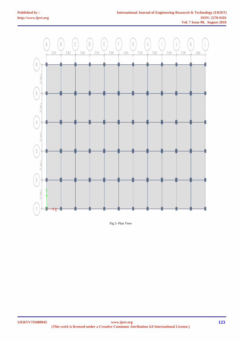
Fig 2- Plan View
International Journal of Engineering Research & Technology (IJERT)
ISSN: 2278-0181http://www.ijert.org
IJERTV7IS080045(This work is licensed under a Creative Commons Attribution 4.0 International License.)
Published by :
www.ijert.org
Vol. 7 Issue 08, August-2018
123

2. Model 2 - X bracing in pairs
Fig 3- Side view and Front view of Model 2
3. Model 3- X bracing alternate arrangement
Fig 4- Side view and Front view of Model 3
International Journal of Engineering Research & Technology (IJERT)
ISSN: 2278-0181http://www.ijert.org
IJERTV7IS080045(This work is licensed under a Creative Commons Attribution 4.0 International License.)
Published by :
www.ijert.org
Vol. 7 Issue 08, August-2018
124
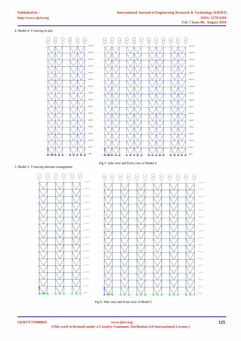
4. Model 4- V bracing in pair
Fig 5- Side view and Front view of Model 4
5. Model 5- V bracing alternate arrangement
Fig 6- Side view and Front view of Model 5
International Journal of Engineering Research & Technology (IJERT)
ISSN: 2278-0181http://www.ijert.org
IJERTV7IS080045(This work is licensed under a Creative Commons Attribution 4.0 International License.)
Published by :
www.ijert.org
Vol. 7 Issue 08, August-2018
125
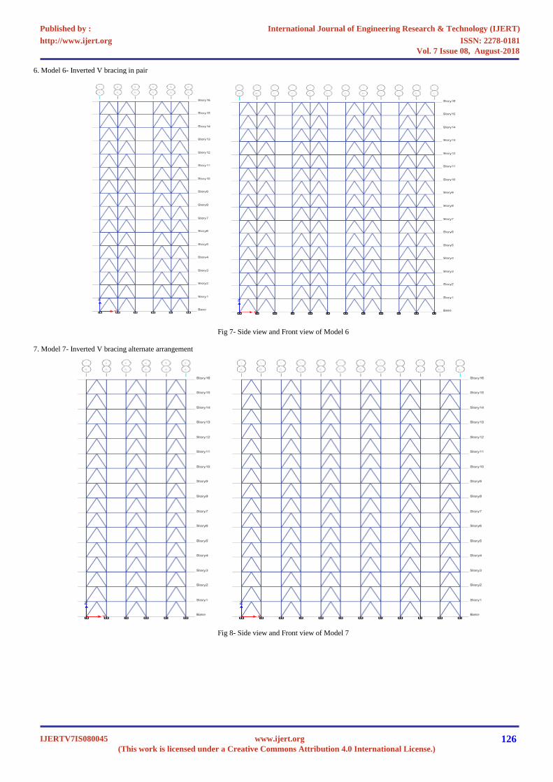
6. Model 6- Inverted V bracing in pair
Fig 7- Side view and Front view of Model 6
7. Model 7- Inverted V bracing alternate arrangement
Fig 8- Side view and Front view of Model 7
International Journal of Engineering Research & Technology (IJERT)
ISSN: 2278-0181http://www.ijert.org
IJERTV7IS080045(This work is licensed under a Creative Commons Attribution 4.0 International License.)
Published by :
www.ijert.org
Vol. 7 Issue 08, August-2018
126
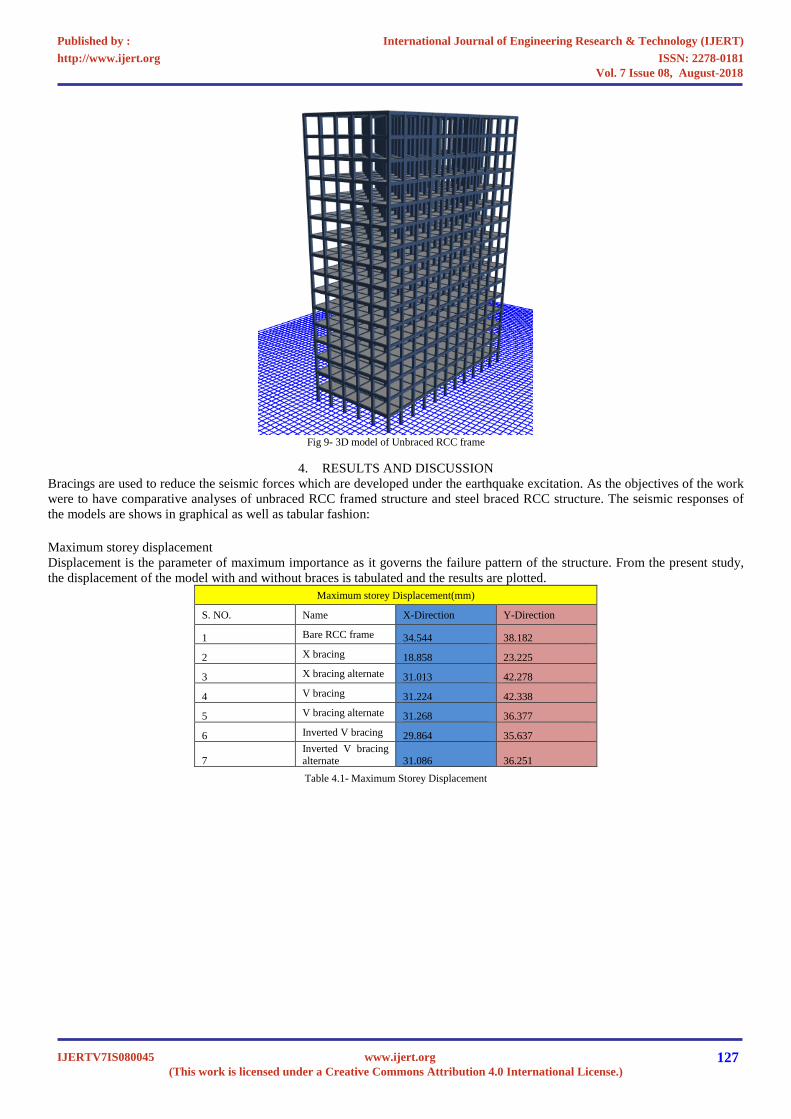
Fig 9- 3D model of Unbraced RCC frame
4. RESULTS AND DISCUSSION
Bracings are used to reduce the seismic forces which are developed under the earthquake excitation. As the objectives of the work were to have comparative analyses of unbraced RCC framed structure and steel braced RCC structure. The seismic responses of the models are shows in graphical as well as tabular fashion:
Maximum storey displacement Displacement is the parameter of maximum importance as it governs the failure pattern of the structure. From the present study, the displacement of the model with and without braces is tabulated and the results are plotted.
Maximum storey Displacement(mm)
S. NO. Name X-Direction Y-Direction
1 Bare RCC frame 34.544 38.182
2 X bracing 18.858 23.225
3 X bracing alternate 31.013 42.278
4 V bracing 31.224 42.338
5 V bracing alternate 31.268 36.377
6 Inverted V bracing 29.864 35.637
7 Inverted V bracing alternate 31.086 36.251
Table 4.1- Maximum Storey Displacement
International Journal of Engineering Research & Technology (IJERT)
ISSN: 2278-0181http://www.ijert.org
IJERTV7IS080045(This work is licensed under a Creative Commons Attribution 4.0 International License.)
Published by :
www.ijert.org
Vol. 7 Issue 08, August-2018
127

Graph 4.1- Comparison of Maximum Storey Displacement
Storey drift Storey drift is the drift of one level of a multi storey building relative to the level below.
Maximum Storey Drift S. NO. Name X-Direction Y-Direction 1 Bare RCC frame 0.001065 0.001075 2 X bracing 0.000517 0.000603 3 X bracing alternate 0.00087 0.001126 4 V bracing 0.000904 0.001147 5 V bracing alternate 0.000922 0.000993 6 Inverted V bracing 0.000866 0.00096
7 Inverted V bracing alternate 0.000912 0.000986
Table 4.2- Maximum Storey Drift
34.544
18.858
31.013 31.224 31.268 29.864
31.086
38.182
23.225
42.278
42.33836.377 35.637
36.251
0mm
05mm
10mm
15mm
20mm
25mm
30mm
35mm
40mm
45mm
Bare RCCframe
X bracing X bracingalternate
V bracing V bracingalternate
Inverted Vbracing
Inverted Vbracingalternate
Max
imum
Sto
rey
Dis
plac
emen
tComparison of Maximum Storey Displacment
X Direction
Y Direction
International Journal of Engineering Research & Technology (IJERT)
ISSN: 2278-0181http://www.ijert.org
IJERTV7IS080045(This work is licensed under a Creative Commons Attribution 4.0 International License.)
Published by :
www.ijert.org
Vol. 7 Issue 08, August-2018
128

Graph 5.2- Comparison of Maximum Storey Drift
Base shear Base shear is an estimate of the maximum expected lateral force that will occur due to seismic ground motion at the base of a
structure. Calculation of base shear depends on:
• Soil condition at site. • The level of ductility and over strength associated with various structural configurations and total weight of the structure • The fundamental (natural) period of vibration of the structure when subjected to dynamic loading
Comparison of Base Shear (in KN)
S. NO. Name X Direction Y Direction
1 Bare RCC frame 3640.4808 3434.6744
2 X bracing 3098.344 2651.5037
3 X bracing alternate 4062.8458 3159.2638
4 V bracing 4011.3911 3126.5164
5 V bracing alternate 4071.3135 3631.4122
6 Inverted V bracing 4296.8971 3771.0553
7 Inverted V bracing alternate 4098.3585 3649.8014
Table 4.3- Comparison of Base Shear
0.001065
0.000517
0.00087
0.000904 0.0009220.000866
0.000912
0.001075
0.000603
0.001126
0.0011470.000993
0.000960.000986
0
0.0002
0.0004
0.0006
0.0008
0.001
0.0012
0.0014
Bare RCC frame X bracing X bracingalternate
V bracing V bracingalternate
Inverted Vbracing
Inverted Vbracing alternate
Stor
ey D
rift
Comparision of Maximum Storey Drift
X Direction
Y Direction
International Journal of Engineering Research & Technology (IJERT)
ISSN: 2278-0181http://www.ijert.org
IJERTV7IS080045(This work is licensed under a Creative Commons Attribution 4.0 International License.)
Published by :
www.ijert.org
Vol. 7 Issue 08, August-2018
129

Graph 4.3- Comparison of Base Shear
Resisting Moments Comparison of Resisting Moments (in KN-m)
S. NO. Name Mx My Mz 1 Bare RCC frame 99043.58 106972.24 62906.41 2 X bracing 75129.73 91786.4 49538.18 3 X bracing alternate 89597.52 118577.05 60380.6 4 V bracing 89362.6 117526.48 59719.39 5 V bracing alternate 104004.44 119435.68 67250.13 6 Inverted V bracing 107877.74 126468.51 70072.75
7 Inverted V bracing alternate 104496.57 120197.71 67612.57
Graph 4.4- Comparison of Resisting Moments
3640.4808
3098.344
4062.8458
4011.3911
4071.3135
4296.8971
4098.3585
3434.6744
2651.5037
3159.2638
3126.5164
3631.4122
3771.0553
3649.8014
0KN 1,000KN 2,000KN 3,000KN 4,000KN 5,000KN
Bare RCC frame
X bracing
X bracing alternate
V bracing
V bracing alternate
Inverted V bracing
Inverted V bracing alternate
Comparision Of Base Shear
Y Direction
X Direction
International Journal of Engineering Research & Technology (IJERT)
ISSN: 2278-0181http://www.ijert.org
IJERTV7IS080045(This work is licensed under a Creative Commons Attribution 4.0 International License.)
Published by :
www.ijert.org
Vol. 7 Issue 08, August-2018
130
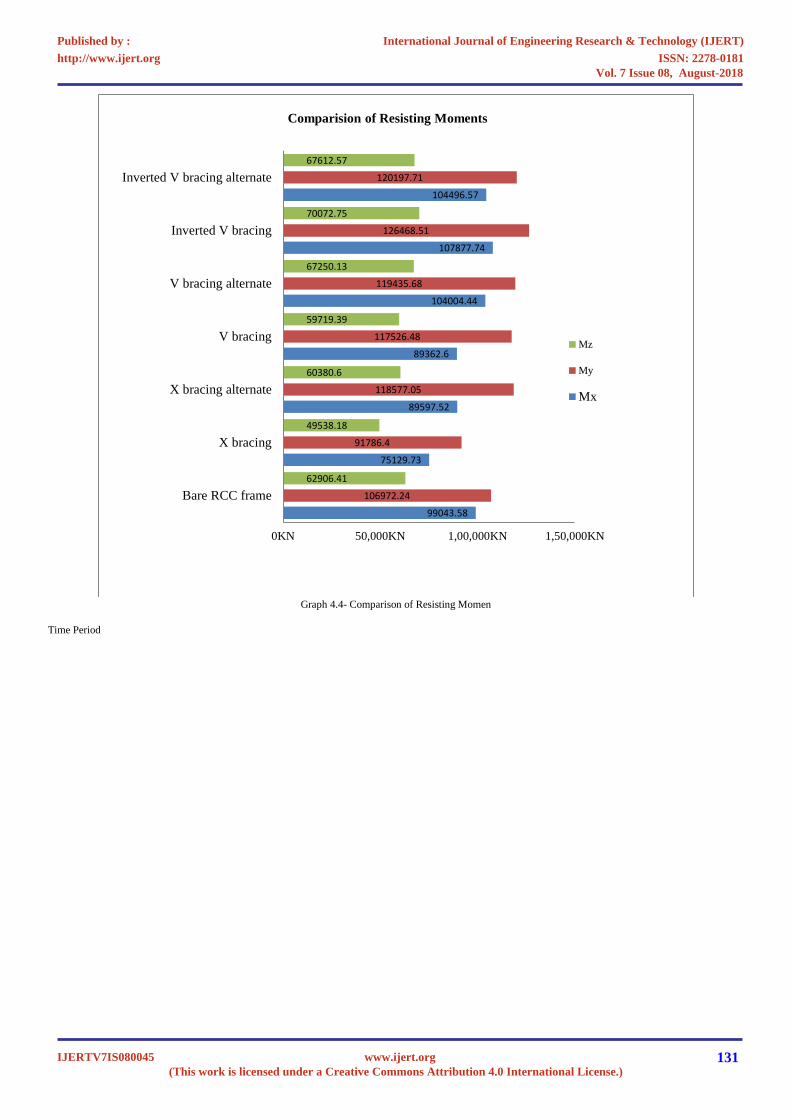
Graph 4.4- Comparison of Resisting Momen
Time Period
99043.58
75129.73
89597.52
89362.6
104004.44
107877.74
104496.57
106972.24
91786.4
118577.05
117526.48
119435.68
126468.51
120197.71
62906.41
49538.18
60380.6
59719.39
67250.13
70072.75
67612.57
0KN 50,000KN 1,00,000KN 1,50,000KN
Bare RCC frame
X bracing
X bracing alternate
V bracing
V bracing alternate
Inverted V bracing
Inverted V bracing alternate
Comparision of Resisting Moments
Mz
My
Mx
International Journal of Engineering Research & Technology (IJERT)
ISSN: 2278-0181http://www.ijert.org
IJERTV7IS080045(This work is licensed under a Creative Commons Attribution 4.0 International License.)
Published by :
www.ijert.org
Vol. 7 Issue 08, August-2018
131

Graph 4.5- Comparison of Time Period
DISPLACEMENT Displacement is the parameter of maximum importance as it governs the failure pattern of the structure. From this present study, the displacement of the model with and without bracings is observed. By providing the bracings to the structure we observe that the displacement of the structure is reduced for X-bracing used in pairs shown in model 2.
0.sec0.05sec
0.1sec0.15sec
0.2sec0.25sec
0.3sec0.35sec
0.4sec0.45sec
0.5sec0.55sec
0.6sec0.65sec
0.7sec0.75sec
0.8sec0.85sec
0.9sec0.95sec
1.sec1.05sec
1.1sec1.15sec
1.2sec1.25sec
1.3sec1.35sec
1.4sec1.45sec
1.5sec1.55sec
1.6sec1.65sec
1.7sec1.75sec
1.8sec1.85sec
1.9sec1.95sec
2.sec2.05sec
2.1sec2.15sec
2.2sec2.25sec
2.3sec2.35sec
2.4sec
0 1 2 3 4 5 6 7 8 9 10 11 12 13
Tim
e Pe
riod
(sec
)
Mode number
Comparison of Time Period Model 1Model 2Model 3Model 4Model 5Model 6Model 7
International Journal of Engineering Research & Technology (IJERT)
ISSN: 2278-0181http://www.ijert.org
IJERTV7IS080045(This work is licensed under a Creative Commons Attribution 4.0 International License.)
Published by :
www.ijert.org
Vol. 7 Issue 08, August-2018
132
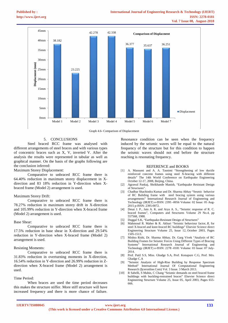
Graph 4.6- Comparison of Displacement
5. CONCLUSIONS Steel braced RCC frame was analysed with different arrangements of steel braces and with various types of concentric braces such as X, V, inverted V. After the analysis the results were represented in tabular as well as graphical manner. On the basis of the graphs following are the conclusion inferred: Maximum Storey Displacement:
Comparative to unbraced RCC frame there is 64.40% reduction in maximum storey displacement in X-direction and 83 18% reduction in Y-direction when X-braced frame (Model 2) arrangement is used.
Maximum Storey Drift: Comparative to unbraced RCC frame there is
78.27% reduction in maximum storey drift in X-direction and 105.99% reduction in Y-direction when X-braced frame (Model 2) arrangement is used.
Base Shear: Comparative to unbraced RCC frame there is
17.5% reduction in base shear in X-direction and 29.54% reduction in Y-direction when X-braced frame (Model 2) arrangement is used.
Resisting Moments: Comparative to unbraced RCC frame there is
31.83% reduction in overturning moments in X-direction, 16.54% reduction in Y-direction and 26.99% reduction in Z-direction when X-braced frame (Model 2) arrangement is used.
Time Period: When braces are used the time period decreases
this makes the structure stiffer. More stiff structure will have increased frequency and there is more chance of failure.
Resonance condition can be seen when the frequency induced by the seismic waves will be equal to the natural frequency of the structure but for this condition to happen the seismic waves should not end before the structure reaching is resonating frequency.
REFERENCE and BOOKS [1] A. Massumi and A. A. Tasnimi “Strengthening of low ductile
reinforced concrete frames using steel X-bracing with different details” The 14th World Conference on Earthquake Engineering October 12-17, 2008, Beijing, China.
[2] Agrawal Pankaj, Shrikhande Manish, “Earthquake Resistant Design of Structures”.
[3] Chadhar Shachindra Kumar and Dr. Sharma Abhay “Sesmic behavior of RC Buliding frame with steel bracing system using various arrangements” International Research Journal of Engineering and Technology (IRJET) e-ISSN: 2395 -0056 Volume: 02 Issue: 05 Aug-2015 p-ISSN: 2395-0072.
[4] Desai J. P., Jain A. K. and Arya A. S., “Seismic response of R. C. braced frames”, Computers and Structures Volume 29 No.4, pp 557568, 1988.
[5] Duggal S.K, “Earthquake-Resistant Design of Structures” [6] Mahmoud R. Maher & R. Akbari “Seismic behaviour factor, R, for
steel X-braced and knee-braced RC buildings” Elsevier Science direct Engineering Structure Volume 25, Issue 12, October 2003, Pages 1505-1513.
[7] Mishra Rishi, Dr. Sharma Abhay, Dr. Garg Vivek “Analysis of RC Building Frames for Seismic Forces Using Different Types of Bracing Systems” International Research Journal of Engineering and Technology (IRJET) e-ISSN: 2278 -0181 Volume: 03 Issue: 07 July-2014.
[8] Prof. Patil S.S, Miss. Ghadge S.A, Prof. Konapure C.G, Prof. Mrs. Ghadge C.A
[9] “Seismic Analysis of High-Rise Building by Response Spectrum Method” International Journal Of Computational Engineering Research (Ijceronline.Com) Vol. 3 Issue. 3 March 2013.
[10] R Sabelli, S Mahin, C Chang “Seismic demands on steel braced frame buildings with buckling-restrained braces” Elsevier Science direct Engineering Structure Volume 25, Issue 05, April 2003, Pages 655-666.
38.182
23.225
42.278 42.338
36.377 35.637 36.251
0mm
5mm
10mm
15mm
20mm
25mm
30mm
35mm
40mm
45mm
Model 1 Model 2 Model 3 Model 4 Model 5 Model 6 Model 7
Dis
plac
men
t (m
m)
Comparison of Displacment
Displacment
International Journal of Engineering Research & Technology (IJERT)
ISSN: 2278-0181http://www.ijert.org
IJERTV7IS080045(This work is licensed under a Creative Commons Attribution 4.0 International License.)
Published by :
www.ijert.org
Vol. 7 Issue 08, August-2018
133
[11] Viswanath K.G, Prakash K.B, Anant Desai “Seismic Analysis of Steel Braced Reinforced Concrete Frames” International Journal of Civil and Structural Engineering Volume: 01 Issn 0976-4399.
[12] IS 1893 (Part I) 2002: “Criteria for earthquake resistant design of structures”.
[13] IS 13920 (1993): “Ductile detailing of reinforced concrete structures subjected to seismic forces”
[14] IS 875 (Part 2):1987 “Code of practice for design loads (other than earthquake) for buildings and structures”.
International Journal of Engineering Research & Technology (IJERT)
ISSN: 2278-0181http://www.ijert.org
IJERTV7IS080045(This work is licensed under a Creative Commons Attribution 4.0 International License.)
Published by :
www.ijert.org
Vol. 7 Issue 08, August-2018
134