TURBINE INLET COOLING ASSOCIATION (TICA) Partial Database ...

International Journal of Science and Research (IJSR) ISSN (Online): 2319-7064
Impact Factor (2012): 3.358
Volume 3 Issue 7, July 2014 www.ijsr.net
Licensed Under Creative Commons Attribution CC BY
Comparative Analysis of Gas Turbine Blades with and without Turbulators
Sagar H T1, Kishan Naik2
1PG Student, Dept. of Studies in Mechanical Engineering, University BDT College of Engineering, Davangere, India
2Assistant Professor, Dept. of Studies in Mechanical Engineering, University BDT College of Engineering, Davangere, India
Abstract: In typical gas turbine engines nozzle guide vanes are (NGV) endure the highest operating temperatures. There exists a great drive in the turbine industry to increase the turbine entry temperature leading to higher thermal efficiency. The present gas turbine engines requires higher entry turbine entry temperatures as engines are operating at higher thrust and thermal efficiency at the same time by operating a turbine at higher temperature reduces the life of blades or vanes because of thermal stresses. Sometimes, the turbine entry temperatures may nearly equal to melting point turbine blade material. Therefore, it is required to cool the blades or vanes to a temperature which gives more life to blades or vanes. The present work aims to determine a better internal cooling configuration which gives optimal temperature distribution on blade surface. Conjugate heat transfer analysis has been carried out to find out the performance and thermal distribution on the existing blade with and without internal cooling on nozzle guide vane by using CFD code ANSYS CFX. In this work, CFD analysis has been carried out using Reynolds average Navier stokes equations. Comparative analysis was done with and without cooling channel on the Nozzle Guide Vane and average temperature on the nozzle guide vane surface will be estimated. Four cooling channels with Turbulators provided better cooling compared to all configurations, because the presence of turbulators provides additional turbulence and increases heat transfer surface area. Higher turbulence provides better heat transfer. Keywords: Gas turbine, Cooling channel, Computational fluid dynamics, Heat transfer. 1. Introduction A turbine is a rotary mechanical device that extracts energy from a combustion chamber and converts it into useful work. A turbine is a turbo machine with at least one moving part called a rotor assembly, which is a shaft or drum with blades attached. Turbine blades move and impart rotational energy to the rotor. Generally Turbine blades are of two types namely, Rotor and Stator. Rotors are rotational blades and the stators are stationary vanes. Since the turbine gets energy from the combustion chamber, the turbine is exposed to high temperature. For this purpose various types of high temperature materials and alloys are used to withstand the high temperature exposed from the combustion chamber. Generally if the outlet temperature of the engine get increased then the efficiency and the performance of the engine get increased, but increasing the temperature causes the turbine material to get damage and leads to engine malfunction. To overcome this malfunction various high temperature withstanding material and alloy are used. But, presently we employed various heat transfer cooling technique which makes the material to withstand more temperature than its critical temperature and makes the increase in efficiency of the engine. [3] Dr. D. A. Rowbury et al [1] numerically investigated cooling research that aims to develop and validate design methods to give maximum cooling effectiveness for minimum cooling flow. The prime objective of this project is to deliver an integrated research package for the development and validation of numerical methods for the design and off design analysis of turbine blade cooling systems. Jenny Sundberg et al [2] numerically investigated the relationship between inlet temperature, specific power and efficiency, have led to great engineering efforts in the attempt to push the temperature to higher and higher levels.
Hasan Nasir et al [3] numerically investigated the turbine blade tip leakage flow from blade pressure side to suction side over the tip surface increases the thermal loading to the blade tip, leading to a high local temperature and thus, is considered one of the primary sources of blade failure. Leakage flow can be reduced by using a Recessed or squealer tip blade or by cooling the blade tip to incorporate film cooling. Experiments were performed for plane tip and squealer tip for different coolant to mainstream blowing ratios of 1.0, 2.0, and 3.0.A transient infrared (IR) thermography technique was used to simultaneously measures heat transfer coefficient and film cooling effectiveness. The Reynolds number based on cascade exit velocity and axial chord length and the inlet and exit Mach numbers were 0.16 and 0.55, respectively. Results showed that performance of the full pressure side squealer was the poorest and that a squealer tip performs better than the plane tip blade. Thermal efficiency of a gas turbine engine can be improved by increasing the turbine inlet gas temperature. As turbine inlet temperature is increased, there is a greater need for more efficient cooling. A turbine blade operates typically at temperature 1650-1750° K, pressure 1.20-1.70 Mpa and in addition to that it rotates at the speeds greater than 3000 rpm. So, efficient cooling mechanisms are needed to improve blade life and overall efficiency of the turbine. Thus heat transfer augmentation inside airfoil internal channels is an important issue for the gas turbine industry. Present material cannot withstand such high thermal stresses in this extreme operating environment of pressure and temperature. Therefore, standard metallic blades with sophisticated cooling techniques have been employed for turbine blades in order to maintain safe and long operation of the turbines under extreme operating conditions [4].
Paper ID: 0201412901 1407

International Journal of Science and Research (IJSR) ISSN (Online): 2319-7064
Impact Factor (2012): 3.358
Volume 3 Issue 7, July 2014 www.ijsr.net
Licensed Under Creative Commons Attribution CC BY
Figure 1: Rib turbulators cooling
To enhance the heat transfer in advanced gas turbine blades, repeated rib turbulence promoters are cast on the two opposite walls (pressure and suction sides) of internal cooling passages. To match the external loads, which can be different at pressure and suction sides, the ribs sometimes can be provided only on one side [5]. 2. Problem Formulation In typical gas turbine engines nozzle guide vanes are (NGV) endure the highest operating temperatures. There exists a great drive in the turbine industry to increase the turbine entry temperature leading to higher thermal efficiency. This has led to drive to increase turbine blade and vane cooling. The present gas turbine engines Requires higher entry turbine entry temperatures as engines are operating at higher thrust and thermal efficiency at the same time by operating a turbine at higher temperature reduces the life of blades or vanes because of thermal stresses. Sometimes, the turbine entry temperatures may nearly equal to melting point turbine blade material. Therefore, it is required to cool the blades or vanes to a temperature which gives more life to blades or vanes. In this work, Conjugate heat transfer analysis will be carried out to find out the performance and thermal distribution on the existing blade with and without internal cooling on nozzle guide vane by using CFD code ANSYS CFX. Here, CFD analysis will be carried out using Reynolds average Navier-stokes equations. Finally comparative analysis will be carried out with and without cooling on the Nozzle Guide Vane and average temperature on the nozzle guide vane surface will be estimated. The current work aims at determining a better internal cooling configuration which gives optimal temperature distribution on blade surface. 3. Numerical Details 3.1 CFD model of blade profile The material of the blade used is Inconel alloy. Inconel alloys are oxidation and corrosion resistant materials, well suited for service in extreme environments subjected to high pressure and kinetic energy. From the literature review, I took computational domain models and boundary conditions as reference and carried out the Solid model with the help of CATIA V5 software package and mesh modeling using ANSYS ICEM CFD. Tetrahedral mesh has been used for the geometry and optimized the mesh for the Turbine Blade.
Figure 2: ICEM CFD model of blade profile
3.2 Boundary condition In this work, Turbine blade with and without cooling has been computed by applying boundary conditions as follows [2], a) Input data Turbine mass flow = 33 kg/s External gas temperature = 1400 K Coolant Inlet temperature = 650 K b) Design Data Number of blades = 33 Blade span = 40mm Blade chord = 68mm Blade external perimeter = 2.2*chord 3.3 Methodology In all of these approaches the same basic procedure is followed. 1. During preprocessing 2. The geometry (physical bounds) of the problem is
defined. 3. The volume occupied by the fluid is divided into discrete
cells (the mesh). The mesh may be uniform or non-uniform.
4. The physical modeling is defined – for example, the equations of motion + enthalpy + radiation + species conservation
5. Boundary conditions are defined. This involves specifying the fluid behaviour and properties at the boundaries of the problem. For transient problems, the initial conditions are also defined.
6. The simulation is started and the equations are solved iteratively as a steady-state or transient.
Finally a postprocessor is used for the analysis and visualization of the resulting solution.
Paper ID: 0201412901 1408

International Journal of Science and Research (IJSR) ISSN (Online): 2319-7064
Impact Factor (2012): 3.358
Volume 3 Issue 7, July 2014 www.ijsr.net
Licensed Under Creative Commons Attribution CC BY
4. Results and Discussions Analysis has been carried out for Turbine blade with and without cooling channel. Here Contour for Temperature has been determined. Finally comparative analysis will be carried out with and without cooling on the Nozzle Guide Vane and average temperature on the nozzle guide vane surface will be estimated. Yellow: curve attached to a single surface - possibly a
hole exists. In some cases this might be desirable for e.g., thin internal walls require at least one curve with single surface attached to it.
Red: curve shared by two surfaces - the usual case. Blue: curve shared by more than two surfaces. Green: Unattached Curves - not attached to any surface. 4.1 Contours for Turbine blade without cooling channel
Figure 3: Temperature contour for NGV without cooling
channel emperature contour for NGV without cooling channel is as shown in fig 3. Static temperature is decreased continuously from inlet to outlet due to increase in velocity from inlet to outlet.
4.2 Contours for Turbine blade with single cooling channel
Figure 4: Temperature contour for NGV with single cooling
channel As there is a decrease in static temperature due to increase in velocity from inlet to outlet, the temperatures of blades decrease continuously from inlet. But at the end there is an increase in temperature due to wake formation i.e. low velocity region. The cooling channel has the highest temperature. Here Turbine blade with single cooling channel, contours for 10% and 7.5% of coolant mass flow rate is almost same. 4.3 Contours for Turbine blade with four cooling channel
Figure 5: Temperature contour for NGV with multi cooling
channel Here, the cooling channel is divided into four discrete channels. As channel is divided, temperature with four
Paper ID: 0201412901 1409

International Journal of Science and Research (IJSR) ISSN (Online): 2319-7064
Impact Factor (2012): 3.358
Volume 3 Issue 7, July 2014 www.ijsr.net
Licensed Under Creative Commons Attribution CC BY
cooling channel will be less compared to single cooling channel.
Figure 6: Temperature Distribution v/s Span Length on Suction Side
The variation of Temperature distribution v/s Span length on suction side for turbine blade with multi cooling channel is as shown in the fig 6. Temperature falls to about 1000k at a span length of 80. From that point, wake formation takes
place and temperature goes on increasing with respect to span length.
Figure 7: Temperature Distribution v/s Span Length on Pessure Side
The variation of Temperature distribution v/s Span length on Pressure side for turbine blade with multi cooling channel is as shown in the fig 7. Here variation of temperature distribution v/s span length is formulated at 20%, 40%, 60% and 80% from the hub. Temperature falls below 1000k at a span length of 80. From that point, wake formation takes place and temperature goes on increasing with respect to span length.
Paper ID: 0201412901 1410
International Journal of Science and Research (IJSR) ISSN (Online): 2319-7064
Impact Factor (2012): 3.358
Volume 3 Issue 7, July 2014 www.ijsr.net
Licensed Under Creative Commons Attribution CC BY
4.4 Contours for Turbine blade multi cooling channel with turbulators
Figure 8: Temperature Contour for NGV multi cooling
channel with turbulators Temperature contour for NGV four cooling channel with turbulators is as shown in fig 8. Blade temperature distribution plot is as same as four channel and single channel graphically except at 50% from leading edge because of ribs provided inside the channel at 40% distance from leading edge, the temperature at 40% distance is less compared to 50% distance.
Figure 9: Temperature on Blade Pressure Section
Temperature on blade pressure section four cooling channel with turbulators is as shown in fig 9. The heat transfer coefficient on pressure side is low compared to suction side as Velocity of the flow in pressure side is more compared to suction side. So, the blade temperatures are high on pressure side compared to suction side.
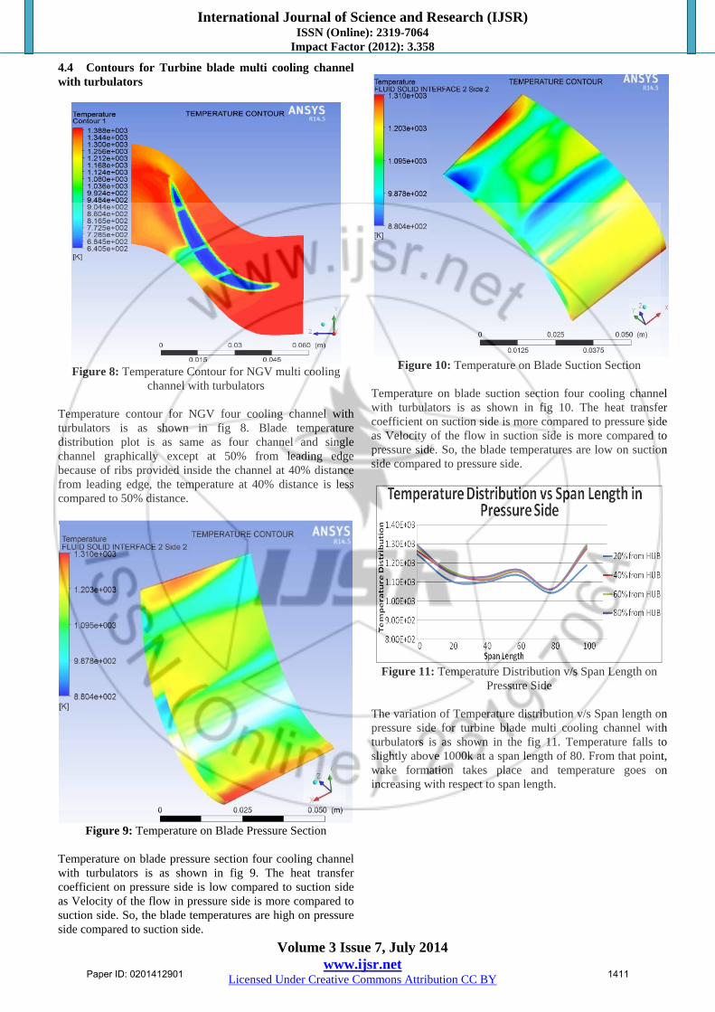
Figure 10: Temperature on Blade Suction Section
Temperature on blade suction section four cooling channel with turbulators is as shown in fig 10. The heat transfer coefficient on suction side is more compared to pressure side as Velocity of the flow in suction side is more compared to pressure side. So, the blade temperatures are low on suction side compared to pressure side.
Figure 11: Temperature Distribution v/s Span Length on
Pressure Side The variation of Temperature distribution v/s Span length on pressure side for turbine blade multi cooling channel with turbulators is as shown in the fig 11. Temperature falls to slightly above 1000k at a span length of 80. From that point, wake formation takes place and temperature goes on increasing with respect to span length.
Paper ID: 0201412901 1411

International Journal of Science and Research (IJSR) ISSN (Online): 2319-7064
Impact Factor (2012): 3.358
Volume 3 Issue 7, July 2014 www.ijsr.net
Licensed Under Creative Commons Attribution CC BY
Figure 12: Temperature Distribution v/s Span Length on
Suction Side The variation of Temperature distribution v/s Span length on Suction side for turbine blade multi cooling channel with turbulators is as shown in the fig 12. Here variation of temperature distribution v/s span length is formulated at 20%, 40%, 60% and 80% from the hub. Temperature falls to 1000k at a span length of 40. From that point, wake formation takes place and temperature goes on increasing with respect to span length. Again at a span length of 80, temperature falls to 1000k and increases with respect to span length due to the formation of wake. Contours for turbine blade multi cooling channel with turbulators (7.5% coolant mass flow rate) is almost same as that of 10% coolant mass flow rate. Hence I have shown contours for only 10% coolant mass flow rate. But has taken the results for 7.5% coolant mass flow rate and tabulated. 4.5 Comparative analysis of cooling channels
Table 1: Area average temperature value for all Blade configurations
S. No Configuration name Area average (Temperature)
BLADE at 10%
Area average (Temperature)
BLADE at 7.5%
1 Turbine blade without
cooling channel 1349.43 [K] 1375.56 [K]
2 Turbine blade with Single
channel 1148.09 [K] 1174.57 [K]
3 Turbine blade with four
cooling channel 1157.54 [K] 1182.99 [K]
4 Turbine blade four cooling channel with Turbulators 1120.11 [K] 1148.98 [K]
From the results and discussion, Comparative analysis of Area average temperature of blade at 10% and 7.5% between turbine blade without cooling channel, with single cooling channel, with four cooling channel and four cooling channel with turbulators has been tabulated. 5. Conclusion • The present work aims to determine a better internal
cooling configuration which gives optimal temperature distribution on blade surface.
• From the results, it is revealed that the turbine blade multi-channel with turbulators shows better cooling compared to four channel and single channel. The average temperature of the blade without cooling is 1349.43 K. The temperature has come down to 1120.11 K due to turbulators with four cooling channel.
• It is also seen that, area average temperature at 10% coolant mass flow rate is less than that of 7.5% coolant mass flow rate. Hence, 10% coolant mass flow rate shows better cooling compared to 7.5% coolant mass flow rate.
• In turbine blade with single channel method, the blade temperature is low compared to multi-channel because in single channel flow, cumulative effect of the cooling is little bit more compared to multi-channel where each channel is divided by walls.
• Four cooling channels with turbulators provided better cooling compared to the configurations, because the presence of turbulators provides additional turbulence and increases heat transfer surface area.
References [1] Dr D.A. Rowbury, Dr S. Parneix, Mr D. Chanteloup and
Prof. A. Lees, “Research into the Influence of Rotation on the Internal Cooling of Turbine Blades”, Paper presented at the RTO AVT Symposium on “Advanced Flow Management: Part B – Heat Transfer and Cooling in Propulsion and Power Systems”, held in Loen, Norway, 7-11 May 2001, and published in RTO-MP-069(I).
[2] Jenny Sunderburg, Sandor Woldendorp and Tiedo Tinga, “Analysis of Combined Convective and Film Cooling on an Existing Turbine Blade”, RTO AVT Symposium on “Advanced Flow Management: Part B – Heat Transfer and Cooling in Propulsion and Power Systems”, held in Leon, Norway, 7-11 May 2001.
[3] Hasan Nasir, Ph.D Thesis, TURBINE BLADE TIP COOLING AND HEAT TRANSFER, B.S., Bangladesh University of Engineering and Technology, 1997, December 2004.
[4] Je Chin Han, Sandip Dutta, and Srinath V Ekkad, “Gas Turbine Heat Transfer and Cooling Technology,” Taylor & Francis, Inc., NewYork, New York, December 2000, ISBN # 1-56032-841-X, 646 pages.
[5] Grzegorz Nowak, Wlodzimierz Wroblewski, 2009, Cooling system optimization of turbine guide vane: 567–572, Applied Thermal Engineering 29
[6] Hylton, Milhec, Turner, Nealy and York.(1983) “Analytical and Experimental Evaluation of the Heat Transfer Distribution Over the Surface of Turbine Vanes”. NASA CR 168015.
[7] York, D. W., and Leylek, J. H.,( 2003),”Three-Dimensional Conjugate Heat Transfer Simulation of an Internally-Cooled Gas Turbine Vane”, ASME Paper No. GT2003-38551.
[8] V Ganeshan, Internal Combustion Engines, Tata McGraw-Hill Education, Second edition, 2002, 777 pages.
[9] S.Z. Shuja, B.S. Yilbas, (2001) "A laminar swirling jet impingement on to an adiabatic wall - Effect of inlet velocity profiles", International Journal of Numerical
Paper ID: 0201412901 1412

International Journal of Science and Research (IJSR) ISSN (Online): 2319-7064
Impact Factor (2012): 3.358
Volume 3 Issue 7, July 2014 www.ijsr.net
Licensed Under Creative Commons Attribution CC BY
Methods for Heat & Fluid Flow, Vol. 11 Iss: 3, pp.237 – 254.
[10] Waseem Siddique, Design of Internal Cooling Passages: Investigation of Thermal Performance of Serpentine Passages, Doctoral Thesis 2011, Royal Institute of Technology, Stockholm, Sweden.
Author Profile
Sagar H T did B.E in Mechanical Engineering from Malnad college of Engineering, Hassan (2008-2012) and pursuing M.Tech. in Thermal Power Engineering from University BDT college of Engineering, Davangere (2012-2014) respectively. At present,
working as assistant professor in RIT, Hassan.
Paper ID: 0201412901 1413