![6G Communication: Envisioning the Key Issues and Challenges · 2020. 6. 9. · arXiv:2004.04024v3 [eess.SP] 7 Jun 2020 1 6G Communication: Envisioning the Key Issues and Challenges](https://static.fdocuments.us/doc/165x107/5feb771c055cdd51f37f3b23/6g-communication-envisioning-the-key-issues-and-challenges-2020-6-9-arxiv200404024v3.jpg)
COMMUNICATION - arXiv
7
COMMUNICATION Please do not adjust margins Wide-field, high-resolution lensless on-chip microscopy via near- field blind ptychographic modulation † Shaowei Jiang, ‡a Jiakai Zhu, ‡a Pengming Song, ‡b Chengfei Guo, ‡a Zichao Bian, a Ruihai Wang, a Yikun Huang, a Shiyao Wang, c He Zhang, a and Guoan Zheng * ab We report a novel lensless on-chip microscopy platform based on near-field blind ptychographic modulation. In this platform, we place a thin diffuser in between the object and the image sensor for light wave modulation. By blindly scanning the unknown diffuser to different x-y positions, we acquire a sequence of modulated intensity images for quantitative object recovery. Different from previous ptychographic implementations, we employ a unit magnification configuration with a Fresnel number of ~50,000, which is orders of magnitude higher than previous ptychographic setups. The unit magnification configuration allows us to have the entire sensor area, 6.4 mm by 4.6 mm, as the imaging field of view. The ultra-high Fresnel number enables us to directly recover the positional shift of the diffuser in the phase retrieval process, addressing the positioning accuracy issue plagued in regular ptychographic experiments. In our implementation, we use a low- cost, DIY scanning stage to perform blind diffuser modulation. Precise mechanical scanning that is critical in conventional ptychography experiments is no longer needed in our setup. We further employ an up-sampling phase retrieval scheme to bypass the resolution limit set by the imager pixel size and demonstrate a half-pitch resolution of 0.78 µm. We validate the imaging performance via in vitro cell cultures, transparent and stained tissue sections, and a thick biological sample. We show that the recovered quantitative phase map can be used to perform effective cell segmentation of the dense yeast culture. We also demonstrate 3D digital refocusing of the thick biological sample based on the recovered wavefront. The reported platform provides a cost- effective and turnkey solution for large field-of-view, high- resolution, and quantitative on-chip microscopy. It is adaptable for a wide range of point-of-care-, global-health-, and telemedicine- related applications. Introduction Optical microscope platform with high numerical aperture (NA) objective lens has long been used for microscale bioimaging. In contrast, lensless on-chip microscopy enables high-resolution imaging without using any lens. It can address the imaging needs of a wide range of lab-on-a-chip applications. Various lensless imaging platforms have been reported in the past years 1-20 . In lensless shadow imaging, the sample is placed on top of the active sensing area of the imager. Object intensity information can be recovered from the captured images via simple filtered back projection 6, 13-15 . Thanks to micron-level short distance between the object plane and the detector, this imaging modality has no stringent coherence requirement on the light source. For other lensless imaging setups, the distance between the object plane and the detector is on the millimetre or centimetre scale. Coherent or partial coherent light source is typically needed for sample illumination. The captured intensity images represent coherent diffraction patterns of the complex object. With no phase-sensitive detector exists, the phase information of the light waves is lost in the acquisition process. This so-called phase problem is inherent to crystallographic, astronomical and optical imaging, or more generally, to all scattering experiments independent of the radiation used. For weakly scattering and sparse objects, the principle of digital in-line holography can be used to recover the complex object 1, 12 . Under more general consideration where a clean reference wave is not present, a phase retrieval process is needed for object recovery. Multiple object heights 4, 16 , multiple incident angles 5, 8, 11 , or multiple wavelengths 7, 17, 21 can be used in the acquisition process to introduce diversity to the phase retrieval process. Recently, we have also demonstrated the use of a translated unknown speckle pattern for lensless phase retrieval 9 . Different implementations of lensless imaging approaches can be found in the recent review papers 22, 23 . a. Department of Biomedical Engineering, University of Connecticut, Storrs, CT, 06269, USA. b. Department of Electrical and Computer Engineering, University of Connecticut, Storrs, CT, 06269, USA. c. Department of Department of Chemical & Biomolecular Engineering, University of Connecticut, Storrs, CT, 06269, USA Email: [email protected] † Electronic Supplementary Information (ESI) available: Fig. S1-S5, Table S1, and Movies S1-S4, See DOI: 10.1039/C9LC01027K ‡ These authors contributed equally to this work.
Transcript of COMMUNICATION - arXiv

COMMUNICATION
Please do not adjust margins
Wide-field, high-resolution lensless on-chip microscopy via near-field blind ptychographic modulation†
Shaowei Jiang,‡a Jiakai Zhu,‡a Pengming Song,‡b Chengfei Guo,‡a Zichao Bian,a Ruihai Wang,a Yikun Huang,a Shiyao Wang,c He Zhang,a and Guoan Zheng *ab
We report a novel lensless on-chip microscopy platform based on
near-field blind ptychographic modulation. In this platform, we
place a thin diffuser in between the object and the image sensor for
light wave modulation. By blindly scanning the unknown diffuser to
different x-y positions, we acquire a sequence of modulated
intensity images for quantitative object recovery. Different from
previous ptychographic implementations, we employ a unit
magnification configuration with a Fresnel number of ~50,000,
which is orders of magnitude higher than previous ptychographic
setups. The unit magnification configuration allows us to have the
entire sensor area, 6.4 mm by 4.6 mm, as the imaging field of view.
The ultra-high Fresnel number enables us to directly recover the
positional shift of the diffuser in the phase retrieval process,
addressing the positioning accuracy issue plagued in regular
ptychographic experiments. In our implementation, we use a low-
cost, DIY scanning stage to perform blind diffuser modulation.
Precise mechanical scanning that is critical in conventional
ptychography experiments is no longer needed in our setup. We
further employ an up-sampling phase retrieval scheme to bypass
the resolution limit set by the imager pixel size and demonstrate a
half-pitch resolution of 0.78 µm. We validate the imaging
performance via in vitro cell cultures, transparent and stained
tissue sections, and a thick biological sample. We show that the
recovered quantitative phase map can be used to perform effective
cell segmentation of the dense yeast culture. We also demonstrate
3D digital refocusing of the thick biological sample based on the
recovered wavefront. The reported platform provides a cost-
effective and turnkey solution for large field-of-view, high-
resolution, and quantitative on-chip microscopy. It is adaptable for
a wide range of point-of-care-, global-health-, and telemedicine-
related applications.
Introduction
Optical microscope platform with high numerical aperture (NA)
objective lens has long been used for microscale bioimaging. In
contrast, lensless on-chip microscopy enables high-resolution
imaging without using any lens. It can address the imaging
needs of a wide range of lab-on-a-chip applications. Various
lensless imaging platforms have been reported in the past
years1-20. In lensless shadow imaging, the sample is placed on
top of the active sensing area of the imager. Object intensity
information can be recovered from the captured images via
simple filtered back projection6, 13-15. Thanks to micron-level
short distance between the object plane and the detector, this
imaging modality has no stringent coherence requirement on
the light source.
For other lensless imaging setups, the distance between the
object plane and the detector is on the millimetre or centimetre
scale. Coherent or partial coherent light source is typically
needed for sample illumination. The captured intensity images
represent coherent diffraction patterns of the complex object.
With no phase-sensitive detector exists, the phase information
of the light waves is lost in the acquisition process. This so-called
phase problem is inherent to crystallographic, astronomical and
optical imaging, or more generally, to all scattering experiments
independent of the radiation used. For weakly scattering and
sparse objects, the principle of digital in-line holography can be
used to recover the complex object1, 12. Under more general
consideration where a clean reference wave is not present, a
phase retrieval process is needed for object recovery. Multiple
object heights4, 16, multiple incident angles5, 8, 11, or multiple
wavelengths7, 17, 21 can be used in the acquisition process to
introduce diversity to the phase retrieval process. Recently, we
have also demonstrated the use of a translated unknown
speckle pattern for lensless phase retrieval9. Different
implementations of lensless imaging approaches can be found
in the recent review papers22, 23.
a. Department of Biomedical Engineering, University of Connecticut, Storrs, CT, 06269, USA.
b. Department of Electrical and Computer Engineering, University of Connecticut, Storrs, CT, 06269, USA.
c. Department of Department of Chemical & Biomolecular Engineering, University of Connecticut, Storrs, CT, 06269, USA
Email: [email protected] † Electronic Supplementary Information (ESI) available: Fig. S1-S5, Table S1, and Movies S1-S4, See DOI: 10.1039/C9LC01027K ‡ These authors contributed equally to this work.

COMMUNICATION
Here we report a novel lensless on-chip microscopy
approach for large field-of-view and high-resolution imaging. In
this platform, we place a thin diffuser in between the object and
the image sensor for light wave modulation. By blindly scanning
the unknown diffuser to different x-y positions, we acquire a
sequence of modulated intensity images for object recovery.
The reported platform shares its root with ptychography, a
lensless imaging approach that was originally proposed for
electron microscopy24 and brought to fruition by Roderburg and
colleagues25. Ptychography requires no phase modulation or
interferometric measurements, enabling coherent diffraction
imaging for visible light, X-rays, and electron9-11, 24-32. A typical
ptychographic dataset is obtained by collecting a sequence of
diffraction patterns in which the object is mechanically scanned
through a spatially confined illumination probe beam. The
confined probe beam limits the physical extent of the object for
each diffraction pattern measurement and serves as a support
constraint for the phase retrieval process. The acquired 2D
images are then jointly processed into an estimate of the
sample’s complex transmission profile.
Different from previous lensless ptychographic
implementations9-11, 25, 27-31, we employ a unit magnification
configuration with a Fresnel number of ~50,000. The unit
magnification configuration allows us to have the entire sensor
area, 6.4 mm by 4.6 mm, as the imaging field of view. The ultra-
high Fresnel number enables us to directly recover the
positional shift of the diffuser in the phase retrieval process,
addressing the positioning accuracy issue plagued in regular
ptychographic experiments33, 34. In our implementation, we use
a low-cost, DIY scanning stage to perform blind diffuser
modulation. Precise mechanical scanning that is critical in
conventional ptychography experiments is no longer needed in
our implementation. We further employ an up-sampling phase
retrieval scheme to bypass the resolution limit set by the pixel
size of the image sensor. Unlike the illumination-based
approach9, 28, 29, the recovered image of our platform only
depends upon how the complex wavefront exits the sample.
Therefore, the sample thickness becomes irrelevant during
reconstruction. After recovery, we can propagate the complex
wavefront to any position along the optical axis.
In the following sections, we will demonstrate the working
principle of our lensless microscope platform and validate the
performance of our prototype device. We show that the
recovered quantitative phase map can be used to perform
effective cell segmentation of the in vitro yeast culture. We also
demonstrate 3D digital refocusing of a thick biological sample
based on the recovered object wavefront. With a compact
configuration and quantitative performance, we envision that
the reported approach can find applications in a wide range of
lab-on-a-chip platforms.
Methods
Near-field blind ptychographic modulation
Figure 1(a) shows the working principle of our lensless imaging
platform. In this platform, we use a 5-mW, 532-nm fiber-
coupled laser diode for sample illumination. We make a thin
diffuser by coating ~1 µm polystyrene beads on a coverslip and
place it in between the object and the image sensor for light
wave modulation. The resulting modulated intensity patterns
are then captured by the image sensor. In this setup, the
distance ‘d’ between the object and the image sensor is ~1 mm,
corresponding to a Fresnel number of ~50,000 (imaging area
divided by ‘d∙wavelength’). A large Fresnel number indicates
little light diffraction from the object plane to the sensor plane.
As such, the motion of the diffuser can be directly tracked from
the captured raw images. To the best of our knowledge, the
Fig. 1 Lensless on-chip microscopy via near-field blind ptychographic diffuser modulation. (a) We place a thin diffuser in between
the object and the image sensor for light wave modulation. The distance between the object and the image sensor is ~1 mm. (b)
The design of the prototype platform. (c) The low-cost, DIY stages for blind diffuser modulation. (d) The cost-effective prototype
setup. Movie S1 shows the 3D design of the reported platform. Movie S2 shows the operation of this prototype device.

COMMUNICATION
Fresnel number of our platform is orders of magnitude higher
than previous ptychographic experiments.
In the acquisition process, we blindly scan the diffuser to
different x-y positions and acquire the modulated intensity
images using an image sensor (MT9J003 ON Semiconductor,
1.67 µm pixel size). We term this scheme ‘near-field blind
ptychographic modulation’, where the word ‘blind’ has twofold
implications. First, it implies the recovery of both the high-
resolution complex object and the diffuser profile at the same
time, similar to the recovery of both probe and object in blind
ptychography30, 35. Secondly, it means we do not have any prior
information of the positional shift of the diffuser. This second
point, to the best of our knowledge, is new in ptychographic
implementations, where precise positional information is
typically required. The positional accuracy problem plagued in
regular ptychography has generated considerable interest in
developing algorithms to refine the positional shift during the
phase retrieval process33, 34. However, these approaches may
fail if a good initial guess of the shift is not available. Thanks to
the ultrahigh Fresnel number, we can directly recover the
positional shift with sub-pixel accuracy. Low-cost random
scanning system can, thus, be used in the reported platform
without any positioning accuracy requirement.
Figure 1(b) shows the design of our prototype device, where
we use two low-cost, DIY mechanical stages to move the
diffuser to x-y different positions. The motion step size is 1-2 µm
in our implementation via motor micro-stepping. We note that
the exact positional shift is treated as unknown in our
experiment. Figure 1(c) shows our low-cost, DIY motion stages
based on Nema-17 stepper motors, linear rail guide, and 8 mm
lead screw (also refer to Figs. S1-S2 and Table S1 in
Supplementary materials). Figure 1(d) shows the entire
prototype platform, where we use the Arduino microcontroller
to control the scanning the x-y stages. Movie S2 shows the
operation of the prototype platform (the motion step size has
been exaggerated for visualization).
Imaging model and the phase retrieval process
The forward imaging model of our platform can be expressed as
��(�, �) = ��(�, �) ∗ �������(��) ∙ ��� − ��, � − ���
∗ �������(��) ∗ ���������
↓�
�
(1)
where ��(�, �) is the jth intensity measurement (� = 1,2, … , �),
�(�, �) is the complex exit wavefront of the object, �(�, �) is
the complex profile of the diffuser, ���, ��� is the jth positional
shift of the diffuser, ‘∙’ stands for point-wise multiplication, and ‘*’ denotes the convolution operation. In Eq. (1), �� is the distance between the object and the diffuser, and �� is the distance between the diffuser and the image sensor. We use �������(�) to model the point spread function (PSF) for free-
space propagation over distance d, and �������� to model the
PSF of the pixel response. Due to the relatively large pixel size, the captured image is a down-sampled version of the diffraction pattern, and we use ‘↓ �’ in the subscript of Eq. (1) to represent the down-sampling process (M = 3 in our implementation). Based on all captured images �� with the diffuser scanned to
different lateral positions ���, ��� s, we aim to recover the
complex exit wavefront of the object �(�, �) and the diffuser profile �(�, �).
Fig. 2 The recovery process of the reported lensless on-chip microscopy platform.
The recovery process is shown in Fig. 2. We first recover the positional shift of the diffuser using cross-correlation. We then initialize the amplitude of the object by averaging all measurements. The diffuser profile is initialized to an all-one matrix. In the iterative reconstruction process, we propagate the object to the diffuser plane and obtain �� in line 7. At the
detector plane, we use the following equation to update the exit wave �� (�, �):
���(�, �) = ��(�, �)(
���(�,�)↑�
�� ��(�,�)��
∗����(�,�)↓�↑�
) (2)
In Eq. (2), the image sizes of ��(�, �) and ��(�, �) are
different. If �� has a size of 100 by 100 pixels, �� will have 300
by 300 pixels (with an up-sampling factor � =3). The term ‘��(�, �)↑�’ represents the nearest-neighbor up-sampling of the
captured image �� . In the denominator of Eq. (2), we first
convolute the term � ��(�, �)��
with an average filter (M by M
all-one matrix). We then perform M-times down-sampling followed by M-times nearest-neighbor up-sampling. This updating process enforces the intensity summation of every M by M small pixels equals the corresponding large pixel in the captured image36. The updating process of Eq. (2) is also the same as that in single-pixel imaging via alternating projection37,
38. With the updated ���(�, �), we then update the object and
the diffuser profiles via Eqs. (3) and (4)39, 40:
��������(�, �) = ��(�, �) +
����(��(�,�))∙����(�,�)���(�,���
�����������(�,�)��
��������(�,�)����
� (3)
��������(�, �) = ��(�, �) +
�������(�,�)�∙����(�,�)���(�,���
�������|��(�,�)|�����|��(�,�)|���� (4)
The phase retrieval process converges within 2-3 iterations in all experiments reported in this work. This is much faster than regular ptychographic experiments where hundreds of iterations are often needed. The fast convergence speed may be due to the use of ultrahigh Fresnel number in our setup. The processing time for 400 raw images with 1024 by 1024 pixels each is ~50 seconds for 2 iterations using a Dell XPS 8930 desktop computer.

COMMUNICATION
Results
Resolution characterization
We first validate the prototype device using a USAF resolution
target in Fig. 3. Figure 3(a) shows the captured raw image of the
resolution target, where the speckle feature comes from the
diffuser modulation process. Figure 3(b) shows the recovered
diffuser profile. Figure 3(c) shows our high-resolution recovery
of the object, where we can resolve 0.78-µm linewidth of group
9, element 3 on the resolution target. We note that the scanning
trajectory can be arbitrary. The lateral scanning step size for the
diffuser is 1-2 µm in the acquisition process. No prior positional
knowledge is needed for the recovery process.
Fig. 3 Validating the reported lensless approach using an amplitude resolution target. (a) The captured raw image. The recovered amplitude of the diffuser (b) and the object (c) based on 400 raw images.
Fig. 4 Validating the quantitative phase imaging nature of the reported approach. (a) The captured raw intensity image of the phase target. (b) The recovered phase image based on 400 raw images. The line trace of the red arc in (b).
Quantitative phase imaging
We also test our prototype using a quantitative phase target
(Benchmark QPT) in Fig. 4. Figure 4(a) shows the captured raw
image with diffuser modulation. Figure 4(b) shows the
recovered quantitative phase using the reported platform. The
line profile across the red dash arc in Fig. 4(b) is plotted in the
inset. The recovered phase is in a good agreement with the
ground-truth of the phase target (two red lines in the inset of
Fig. 4(b)). We have also tested the phase imaging performance
using an unstained mouse kidney slide (Fig. 5(a)) and
transparent U87 cell culture (Fig. 5(b)). Figure 5(a1) and 5(b1)
show the captured raw images. Figure 5(a2) and 5(b2) show the
recovered quantitative phase of the two samples. Movie S3
shows the phase retrieval process of the unstained mouse
kidney slide. Figures S3 and S4 show the recovered full field-of-
view phase images of HeLa cell and U87 cell cultures. The
quantitative phase imaging capability of the reported platform
offers a label-free solution for cell-assay-related applications41.
Fig. 5 Testing of the reported approach using an unstained mouse kidney slide (a) and U87 cell culture (b). In this experiment, we directly use the recovered diffuser profile from the previous experiment. (a1), (b1) The captured raw images. (a2), (b2) The recovered phase profiles using 100 raw images. Movie S3 shows the recovery process.
Fig. 6 Testing the reported platform using a thick potato sample. (a) The recovered amplitude of the object’s exit wavefront. (b) The three images after digitally propagating to three different axial positions. Movie S4 shows the digital propagation process.
Another advantage of the reported platform is to perform diffuser modulation at the detection path. Different from illumination-based approach9, 28, 29, the recovered image of our platform only depends upon how the complex wavefront exits the sample40, 42, 43. Therefore, the sample thickness becomes irrelevant during reconstruction. After recovery, we can
COMMUNICATION
propagate the complex wavefront to any position along the optical axis. We validate this point using a thick potato sample in Fig. 6. Figure 6(a) shows the recovered amplitude of the object exit wavefront. Figure 6(b1)-6(b3) show the recovered object amplitude after digitally propagating to z = 620 µm, z = 650 µm, and z = 685 µm. The cell walls are in focus in Fig. 6(b1) and the organelles are in focus in Fig. 6(b2)-6(b3).
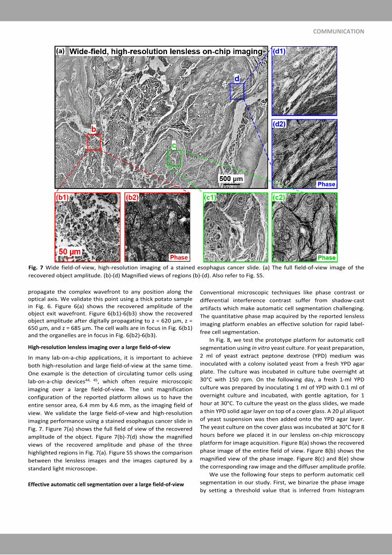
High-resolution lensless imaging over a large field-of-view
In many lab-on-a-chip applications, it is important to achieve
both high-resolution and large field-of-view at the same time.
One example is the detection of circulating tumor cells using
lab-on-a-chip devices44, 45, which often require microscopic
imaging over a large field-of-view. The unit magnification
configuration of the reported platform allows us to have the
entire sensor area, 6.4 mm by 4.6 mm, as the imaging field of
view. We validate the large field-of-view and high-resolution
imaging performance using a stained esophagus cancer slide in
Fig. 7. Figure 7(a) shows the full field of view of the recovered
amplitude of the object. Figure 7(b)-7(d) show the magnified
views of the recovered amplitude and phase of the three
highlighted regions in Fig. 7(a). Figure S5 shows the comparison
between the lensless images and the images captured by a
standard light microscope.
Effective automatic cell segmentation over a large field-of-view
Conventional microscopic techniques like phase contrast or
differential interference contrast suffer from shadow-cast
artifacts which make automatic cell segmentation challenging.
The quantitative phase map acquired by the reported lensless
imaging platform enables an effective solution for rapid label-
free cell segmentation.
In Fig. 8, we test the prototype platform for automatic cell
segmentation using in vitro yeast culture. For yeast preparation,
2 ml of yeast extract peptone dextrose (YPD) medium was
inoculated with a colony isolated yeast from a fresh YPD agar
plate. The culture was incubated in culture tube overnight at
30°C with 150 rpm. On the following day, a fresh 1-ml YPD
culture was prepared by inoculating 1 ml of YPD with 0.1 ml of
overnight culture and incubated, with gentle agitation, for 1
hour at 30°C. To culture the yeast on the glass slides, we made
a thin YPD solid agar layer on top of a cover glass. A 20 µl aliquot
of yeast suspension was then added onto the YPD agar layer.
The yeast culture on the cover glass was incubated at 30°C for 8
hours before we placed it in our lensless on-chip microscopy
platform for image acquisition. Figure 8(a) shows the recovered
phase image of the entire field of view. Figure 8(b) shows the
magnified view of the phase image. Figure 8(c) and 8(e) show
the corresponding raw image and the diffuser amplitude profile.
We use the following four steps to perform automatic cell
segmentation in our study. First, we binarize the phase image
by setting a threshold value that is inferred from histogram
Fig. 7 Wide field-of-view, high-resolution imaging of a stained esophagus cancer slide. (a) The full field-of-view image of the
recovered object amplitude. (b)-(d) Magnified views of regions (b)-(d). Also refer to Fig. S5.

COMMUNICATION
analysis. As such, we separate the yeast cells from the
background. Second, we perform seed-point extraction based
on local maxima detection. Third, we perform watershed
transform to perform cell segmentation. Fourth, we refine the
segmentation result based on the prior information of the cell
size. In this refinement process, we first identify the segmented
regions that are at least two times larger than the average cell
area. We then enhance the image contrast of those regions and
repeat steps 2 and 3. Figure 8(d) shows the result of automatic
cell segmentation (different segmented cells are coded with
different colours). For a 200-µm square region, there are 1550
cells via our automatic segmentation approach discussed above.
For the same region, we have an average of 1568 cells via
manual counting by three persons. The difference between the
two is only about 1%, validating the effectiveness of the
reported segmentation method using the quantitative phase
map. For the entire field-of-view, the total number of yeast cells
is 641,690 via our automatic cell segmentation approach and
the processing time is 15 seconds. The reported automatic cell
segmentation over a large field-of-view may find a wide range
of applications from drug discovery to single-cell biology.
Discussions and conclusions
In summary, we report a novel lensless on-chip imaging
platform for wide-field, high-resolution microscopy. In this
platform, we place a thin diffuser in between the object and the
image sensor for light wave modulation. By blindly scanning the
unknown diffuser to different x-y positions, we acquire a
sequence of modulated intensity images for object recovery.
We demonstrate a half-pitch resolution of 0.78 µm and test the
imaging performance using various confluent biological
samples. We also demonstrate effective automatic cell
segmentation based on the quantitative phase map generated
by the reported platform.
There are several unique advantages of the reported
platform. First, different from previous ptychographic
implementations, the unit magnification configuration allows us
to have the entire sensor area, 6.4 mm by 4.6 mm, as the
imaging field of view. Second, thanks to the ultra-high Fresnel
number, the speckle feature from the diffuser can be clearly
resolved from the captured intensity images. Therefore, we can
directly recover the unknown positional shifts via image cross-
correlation. Precise mechanical scanning that is critical in
conventional ptychography experiments is no longer needed in
our implementation. Third, different from the pixel super-
resolution technique employed in conventional lensless on-chip
imaging setups3, 13, 15, 16, 22, the reported platform can achieve
sub-pixel resolution using an up-sampling phase retrieval
scheme. Fourth, since we modulate the light wave at the
detection path, the recovered image only depends upon how
the complex wavefront exits the sample. After recovery, we can
propagate the complex wavefront to any position along the
Fig. 8 Wide field-of-view, high-resolution imaging of in vitro confluent yeast culture. (a) The recovered phase image of the yeast
culture. (b) The magnified view of the yeast culture. The size of individual yeast cell is 3-4 µm. (c) The captured raw image
corresponding to region shown in (b). (d) The segmentation result based on the proposed four-step procedure. Different cells are
coded with different colours. (e) The recovered diffuser profile corresponding to region shown in (b). Also refer to Figs. S3-S4 for
the recovered phase images of HeLa cell and U87 cell cultures.

COMMUNICATION
optical axis. Lastly, our phase retrieval process typically
converges within 2-3 iterations, which are much faster than
regular ptychographic implementations. This may be due to the
ultrahigh Fresnel number of our setup. Further research along
this line is highly desired.
Contributions
S. J., J. Z., P. S., C. G. contributed equally to the work and develop
the reported prototype platform. G. Z. conceived the idea and
planned the study. H. Z. performed the initial test. Z. B., S. W.,
Y. H. prepared the cell culture samples. All authors contributed
to writing and correcting the manuscript.
Conflicts of interest
There are no conflicts to declare.
Acknowledgments
G. Z. acknowledges the support of the National Science
Foundation 1510077, 1555986, and 1700941.
Notes and references
1. W. Xu, M. Jericho, I. Meinertzhagen and H. Kreuzer, Proceedings of the National Academy of Sciences, 2001, 98, 11301-11305.
2. L. Repetto, E. Piano and C. Pontiggia, Optics letters, 2004, 29, 1132-1134.
3. W. Bishara, T.-W. Su, A. F. Coskun and A. Ozcan, Opt. Express, 2010, 18, 11181-11191.
4. A. Greenbaum, U. Sikora and A. Ozcan, Lab on a Chip, 2012, 12, 1242-1245.
5. W. Luo, A. Greenbaum, Y. Zhang and A. Ozcan, Light: Science & Applications, 2015, 4, e261.
6. G. Zheng, S. A. Lee, Y. Antebi, M. B. Elowitz and C. Yang, Proceedings of the National Academy of Sciences, 2011, 108, 16889-16894.
7. C. Zuo, J. Sun, J. Zhang, Y. Hu and Q. Chen, Optics express, 2015, 23, 14314-14328.
8. Z. Zhang, Y. Zhou, S. Jiang, K. Guo, K. Hoshino, J. Zhong, J. Suo, Q. Dai and G. Zheng, APL Photonics, 2018, 3, 060803.
9. H. Zhang, Z. Bian, S. Jiang, J. Liu, P. Song and G. Zheng, Opt. Lett., 2019, 44, 1976-1979.
10. A. M. Maiden, J. M. Rodenburg and M. J. Humphry, Opt. Lett., 2010, 35, 2585-2587.
11. P. Li and A. Maiden, Applied Optics, 2018, 57, 1800-1806. 12. A. Feizi, Y. Zhang, A. Greenbaum, A. Guziak, M. Luong, R. Y. L.
Chan, B. Berg, H. Ozkan, W. Luo, M. Wu, Y. Wu and A. Ozcan, Lab on a Chip, 2016, 16, 4350-4358.
13. S. A. Lee and C. Yang, Lab on a Chip, 2014, 14, 3056-3063. 14. S. A. Lee, J. Erath, G. Zheng, X. Ou, P. Willems, D. Eichinger, A.
Rodriguez and C. Yang, PLOS ONE, 2014, 9, e89712. 15. G. Zheng, S. A. Lee, S. Yang and C. Yang, Lab on a Chip, 2010, 10,
3125-3129. 16. J. Zhang, J. Sun, Q. Chen, J. Li and C. Zuo, Scientific reports, 2017,
7, 11777. 17. D. W. E. Noom, K. S. E. Eikema and S. Witte, Opt. Lett., 2014, 39,
193-196.
18. F. Momey, A. Berdeu, T. Bordy, J.-M. Dinten, F. K. Marcel, N. Picollet-D’Hahan, X. Gidrol and C. Allier, Biomed. Opt. Express, 2016, 7, 949-962.
19. A. Berdeu, B. Laperrousaz, T. Bordy, O. Mandula, S. Morales, X. Gidrol, N. Picollet-D’hahan and C. Allier, Scientific Reports, 2018, 8, 16135.
20. L. Hervé, O. Cioni, P. Blandin, F. Navarro, M. Menneteau, T. Bordy, S. Morales and C. Allier, Biomed. Opt. Express, 2018, 9, 5828-5836.
21. P. Bao, F. Zhang, G. Pedrini and W. Osten, Optics Letters, 2008, 33, 309-311.
22. A. Ozcan and E. McLeod, Annual review of biomedical engineering, 2016, 18, 77-102.
23. A. Greenbaum, W. Luo, T.-W. Su, Z. Göröcs, L. Xue, S. O. Isikman, A. F. Coskun, O. Mudanyali and A. Ozcan, Nature Methods, 2012, 9, 889.
24. Y. Jiang, Z. Chen, Y. Han, P. Deb, H. Gao, S. Xie, P. Purohit, M. W. Tate, J. Park and S. M. Gruner, Nature, 2018, 559, 343.
25. H. M. L. Faulkner and J. Rodenburg, Physical review letters, 2004, 93, 023903.
26. F. Pfeiffer, Nature Photonics, 2018, 12, 9-17. 27. F. Zhang, B. Chen, G. R. Morrison, J. Vila-Comamala, M. Guizar-
Sicairos and I. K. Robinson, Nature communications, 2016, 7, 13367.
28. M. Stockmar, P. Cloetens, I. Zanette, B. Enders, M. Dierolf, F. Pfeiffer and P. Thibault, Scientific reports, 2013, 3, 1927.
29. H. Zhang, S. Jiang, J. Liao, J. Deng, J. Liu, Y. Zhang and G. Zheng, Opt. Express, 2019, 27, 7498-7512.
30. A. M. Maiden and J. M. Rodenburg, Ultramicroscopy, 2009, 109, 1256-1262.
31. M. Guizar-Sicairos and J. R. Fienup, Opt. Express, 2008, 16, 7264-7278.
32. P. Thibault, M. Dierolf, A. Menzel, O. Bunk, C. David and F. Pfeiffer, Science, 2008, 321, 379-382.
33. F. Zhang, I. Peterson, J. Vila-Comamala, A. Diaz, F. Berenguer, R. Bean, B. Chen, A. Menzel, I. K. Robinson and J. M. Rodenburg, Opt. Express, 2013, 21, 13592-13606.
34. M. Beckers, T. Senkbeil, T. Gorniak, K. Giewekemeyer, T. Salditt and A. Rosenhahn, Ultramicroscopy, 2013, 126, 44-47.
35. P. Thibault, M. Dierolf, O. Bunk, A. Menzel and F. Pfeiffer, Ultramicroscopy, 2009, 109, 338-343.
36. D. Batey, T. Edo, C. Rau, U. Wagner, Z. Pešić, T. Waigh and J. Rodenburg, Physical Review A, 2014, 89, 043812.
37. K. Guo, S. Jiang and G. Zheng, Biomed. Opt. Express, 2016, 7, 2425-2431.
38. L. Bian, J. Suo, Q. Dai and F. Chen, J. Opt. Soc. Am. A, 2018, 35, 78-87.
39. A. Maiden, D. Johnson and P. Li, Optica, 2017, 4, 736-745. 40. P. Song, S. Jiang, H. Zhang, Z. Bian, C. Guo, K. Hoshino and G.
Zheng, Opt. Lett., 2019, 44, 3645-3648. 41. Y. Park, C. Depeursinge and G. Popescu, Nature Photonics, 2018,
12, 578-589. 42. S. Dong, R. Horstmeyer, R. Shiradkar, K. Guo, X. Ou, Z. Bian, H.
Xin and G. Zheng, Opt. Express, 2014, 22, 13586-13599. 43. B. Zichao, J. Shaowei, S. Pengming, Z. He, H. Pouria, H. Kazunori
and Z. Guoan, Journal of Physics D: Applied Physics, 2019. 44. Y. Zheng, Q. Li, W. Hu, J. Liao, G. Zheng and M. Su, Lab on a Chip,
2019. 45. A. J. Williams, J. Chung, X. Ou, G. Zheng, S. Rawal, Z. Ao, R. Datar,
C. Yang and R. J. C. M.D., Journal of Biomedical Optics, 2014, 19, 1-8, 8.
![Energy Efficient Federated Learning Over Wireless … · 2019-11-07 · arXiv:1911.02417v1 [cs.IT] 6 Nov 2019 1 Energy Efficient Federated Learning Over Wireless Communication Networks](https://static.fdocuments.us/doc/165x107/5fac82d954ace821e75f6a90/energy-eficient-federated-learning-over-wireless-2019-11-07-arxiv191102417v1.jpg)
![Throughput Maximization in Wireless Powered ...arXiv:1304.7886v4 [cs.IT] 21 Jul 2014 Throughput Maximization in Wireless Powered Communication Networks Hyungsik Ju and Rui Zhang Abstract](https://static.fdocuments.us/doc/165x107/5e9602c0573273188b47b1d3/throughput-maximization-in-wireless-powered-arxiv13047886v4-csit-21-jul.jpg)
![arXiv · arXiv:1203.4212v1 [math.PR] 19 Mar 2012 Asymptoticpropertiesoftheprocesscountedwitharandom characteristicinthecontextoffragmentationprocesses RobertKnobloch ...](https://static.fdocuments.us/doc/165x107/5f42d1f36d483d14534a9ec6/arxiv-arxiv12034212v1-mathpr-19-mar-2012-asymptoticpropertiesoftheprocesscountedwitharandom.jpg)

![arXiv:1801.08825v1 [cs.CY] 26 Jan 2018 · knowledge, participation and voting (Prior,2007), news consumption (Althaus & Tewksbury,2002) and political communication (Druckman et al.,2010).](https://static.fdocuments.us/doc/165x107/60187f329a2d1647ab7037b4/arxiv180108825v1-cscy-26-jan-2018-knowledge-participation-and-voting-prior2007.jpg)
![, Dena Firoozi and Abstract. arXiv:2003.04938v3 [q-fin.MF ... · a MFG formulation of cellular communication networks. MFGs have found numerous applications in engineering [5,23,46],](https://static.fdocuments.us/doc/165x107/5f0fff5b7e708231d446ee7e/-dena-firoozi-and-abstract-arxiv200304938v3-q-finmf-a-mfg-formulation.jpg)
![Near-Field Passive RFID Communication: Channel Model ...arXiv:1309.5262v2 [cs.IT] 21 Mar 2014 1 Near-Field Passive RFID Communication: Channel Model and Code Design Angela I. Barbero,](https://static.fdocuments.us/doc/165x107/60b8c04abe33e75a927e7a71/near-field-passive-rfid-communication-channel-model-arxiv13095262v2-csit.jpg)

![Abstract. arXiv:1609.00184v2 [astro-ph.IM] 16 Dec 2016 · aIndian Institute of Astrophysics, Bangalore, India Abstract. ... Real-time communication with the payload on small balloons](https://static.fdocuments.us/doc/165x107/5f04a1c97e708231d40eeec3/abstract-arxiv160900184v2-astro-phim-16-dec-2016-aindian-institute-of-astrophysics.jpg)
![Modeling radio communication blackout and …arXiv:1407.6635v2 [physics.comp-ph] 12 Nov 2014 Draft copy for AIAA Journal of Spacecraft and Rockets Modeling radio communication blackout](https://static.fdocuments.us/doc/165x107/5e852f565f043200960681cd/modeling-radio-communication-blackout-and-arxiv14076635v2-12-nov-2014-draft.jpg)
![Deep Learning based End-to-End Wireless Communication ...arXiv:1903.02551v1 [cs.IT] 6 Mar 2019 1 Deep Learning based End-to-End Wireless Communication Systems with Conditional GAN](https://static.fdocuments.us/doc/165x107/5fb22ea478de9424234c419b/deep-learning-based-end-to-end-wireless-communication-arxiv190302551v1-csit.jpg)


![Adaptive Deployment for UAV-Aided Communication Networks · arXiv:1812.03267v1 [cs.IT] 8 Dec 2018 Adaptive Deployment for UAV-Aided Communication Networks Zhe Wang, Member, IEEE,](https://static.fdocuments.us/doc/165x107/5f2cbbd98f78d66232514643/adaptive-deployment-for-uav-aided-communication-networks-arxiv181203267v1-csit.jpg)
![arXiv:1605.08309v1 [cs.NI] 26 May 2016Miami, FL 33174 E-mail: akumb004@fiu.edu arXiv:1605.08309v1 [cs.NI] 26 May 2016 2 Abhaykumar Kumbhar near field communication (NFC) devices,](https://static.fdocuments.us/doc/165x107/5ec9509959da107b72796b1e/arxiv160508309v1-csni-26-may-2016-miami-fl-33174-e-mail-akumb004iuedu.jpg)
