Come toward the Light: A Post Biblical Project in …crose/428_html/proposals_various/Over... · A...
12
Come toward the Light: A Post Biblical Project in Luminal Navigation Ji Hoon Baik Mike Sherman Faizan Wajid 12/21/2010
-
Upload
vuonghuong -
Category
Documents
-
view
213 -
download
0
Transcript of Come toward the Light: A Post Biblical Project in …crose/428_html/proposals_various/Over... · A...

Come toward the Light:
A Post Biblical Project in Luminal
Navigation
Ji Hoon Baik
Mike Sherman
Faizan Wajid
12/21/2010

1. Objectives
The goal of this project is to design an indoor navigation system that uses the fluorescent lights
in the building of its intended use as location information sources. It shall be demonstrated that a
fluorescent light, with proper modifications to its ballast, can be modulated with location
information by frequency shift keying (FSK) digital modulation scheme. A receiver system that
can discriminatingly demodulate the location information signals of multiple fluorescent light
fixtures will be constructed. The receiver will be designed to send the demodulated location
information to a laptop computer with proper software that can generate instructions that guide
the user of the device from Point A to Point B in the building.
2. History of the Fluorescent Light Communication and Its Use in Navigation Systems
The idea of using fluorescent light for communication has been an active area of research for the
past few decades. In 2001, a team of researchers from MIT and Cambridge University
successfully demonstrated with a working prototype that fluorescent light can transmit data
either in digital or analog form with sufficient bandwidth, and ascertained the prospect of using
this technology for practical applications. One of the demonstrations included the transmission of
music from a fluorescent light. A fluorescent lamp was specially designed to modulate a song on
its light. Shining the lamp on a receiver connected to an audio system made its speakers play the
music.
In 2007, an enterprise called Talking Lights launched a line of products that implemented the
fluorescent light communication technique. Their products are currently on the market. They
include a patented fluorescent ballast/modulator, a PCMCIA receiver that attaches to a personal
computer as a peripheral device, and receiver software that decodes modulated fluorescent lights.
Called Talking Light Location Beacon Ballast, the specially designed ballast can serve as a
location source by producing fluorescent light, modulated with the location information of the
lamp. When a person holding the PCMCIA receiver approaches the lamp, the receiver detects the
modulated light, decodes the location information conveyed in the light, and relays this
information to the person’s computer. The company describes their technology as a type of
wireless local area network (LAN) that establish communication link through fluorescent light.
3. Applications of the Fluorescent Light Navigation System.
The fluorescent light navigation system can be used for:
a. Supporting people with brain injury or dementias that lack spatial cognizance in hospitals.
b. Providing dynamic map information and location determination in museums.
The fluorescent light modulation can also be used to create a wireless mesh network for:
a. Transmitting announcements/alerts to various parts of a building in case of emergency.
b. Communication between two locations within a building.
4. Advantages over Conventional Wireless Network.
The wireless network that uses fluorescent lights as location sources offers several advantages
over the wireless network that uses radio frequencies:

a. It’s cheap. Most buildings today are already equipped with fluorescent light infrastructure.
Retrofitting these buildings with the specially modified ballasts does not entail any
significant cost.
b. The installation of the network is easy. It can be as simple as changing the ballasts of the
lamps in the building, and distributing proper receiver devices to those in need of the
technology.
c. It consumes less power. Each fluorescent light is a location information transmitter, and
the power used for transmission is simply the power needed to keep the light on.
d. It is ideal for indoor navigation systems. Fluorescent lights are found in almost every part
of a building. The receiver and the light fixtures on the ceiling are most likely to be in
each other’s line of sight time and again. Unless an action that blocks the light from the
receiver is performed purposefully, the communication link between the lights and the
receiver will not be interrupted as the receiver is moved around the building. On the
contrary, navigation systems that use radio frequencies are more prone to communication
failures because radio waves tend to interact with various obstacles in the building and
are susceptible electromagnetic interference.
5. How Is This Project Different from Talking Lights?
The Talking Lights uses the patented Talking Light Location Beacon Ballast. No detailed inner
workings of this device have yet been released to the public, except that the device uses PCM
digital modulation technique. This project is different from the Talking Lights in that:
a. The ballast uses the FSK digital modulation scheme.
b. The receiver uses a CDMA Approach to Identifying the lamp of the closest distance.
6. How It Works
Overview
A ballast is the component of fluorescent light fixtures that regulate the AC current flowing into
the electrodes of the fluorescent bulb. The rate of flicker of the fluorescent light is approximately
twice the AC current supplied by the ballast.
As all navigation systems do, the receiver system that provides the user with path-finding
instruction needs some form of signals that can be captured from its surroundings and allows it to
locate the user’s current position on the map. In the fluorescent navigation system, the
fluorescent light shall serve as this location information sources. This is achieved by using a new
type of ballast, redesigned with an added functionality that allows it to produce light that is FSK-
modulated with location information, which will be called ―location ID‖ from this point on.
More specifically, the ballast switches the AC current of the lamp rapidly between two discrete
frequencies. This way, the ballast can produce light signals that flicker alternately at two
different frequencies. This is equivalent to FSK-modulating the light signal.
Note that the ballast being discussed is special-purpose high-efficiency electronic ballast, which
is capable of producing fluorescent light flickering at a much higher frequency than the
conventional, inexpensive magnetic ballast.

The navigation system is targeted for small-sized buildings where fluorescent lights are prevalent
throughout each floor level, presumably installed on the ceilings of the building.
Each fluorescent lamp in the building shall be equipped with this newly modified ballast, and a
unique location ID will be assigned to it. The location IDs of all the lamps shall form a mutually
orthogonal set, so that the receiver may use them as CDMA signatures as part of its
demodulation scheme.
The ballast modulates the lamp with its unique location ID, and this location information is
transmitted constantly to the light’s surrounding whenever the light is turned on. When a person
holding the receiver approaches any fluorescent-lit area in the building, the receiver perceives its
location within the building by demodulating the location ID of the lamp closest to its position.

The receiver relays the location information to the laptop via a wire interface, and the software in
the laptop calculates the optimal path for the user to his desired destination.
How the Fluorescent Light is Modulated by the Ballast
To obtain the ability to control the light’s drive frequency, we must design and build our own
ballast. This ability is not needed in existing commercial ballasts, and so such ability is not
available in off-the-shelf parts. However, we can take a reference design, and modify it to suit
our requirements, removing the most complex part of the design.
Because fluorescent lights operate at around 125 volts, and are powered from 110 volt (US) line
power, there are safety concerns inherent in the execution of this project. By using a design as
close to a known good reference, as well as taking common sense precautions, the risk of
personal injury or equipment damage can be minimized.
Old style fluorescent lights use reactive ballasts to control the current entering the lamp, however
the operating frequency of these is that of the line AC, and they are thus unsuitable for our
project. Instead, we turn to high frequency, electronic ballasts.
High frequency ballasts are based on switched mode power supplies. These power supplies first
convert the incoming AC to DC via a full wave rectifier, followed by a filter. The DC is then
converted back to AC at a much higher frequency via a power oscillator, called a chopper, which
can adjust its average output via PWM. A transformer isolates the output from the line power,
and converts to the voltage we need. Finally, the chopper controller compares the output voltage
to a reference value, and provides feedback to the chopper, stabilizing the output.

We are concerned only with the chopper, as it determines the drive frequency of the fluorescent
light. In most commercial ballasts, the chopper is implemented with an IC called a PWM switch
mode regulator. By finding one with an external frequency control, we can accomplish the
modulation. An example is the National Semiconductor LM5002, its operating frequency is
determined via a resistance, but it can also be synchronized with an incoming pulse sequence.
In our application, we are using a microcontroller of some variety to control the ballast. For ease
of prototyping and programming, an Arduino is a strong candidate; however a cheaper, more
limited one would bring down mass production costs. The microcontroller’s function is to
receive or store the message to transmit, as well as sending a signal to the PWM regulator.
Role of the Ballast
With the aforementioned modifications, the ballast can change the instantaneous frequency of
the AC current it supplies to the electrodes of the fluorescent lamp. Then, the ballast can be used
to FSK-modulate the flicker rate—and therefore the intensity—of the lamp light with its location
ID. The location ID is a unique sequence of 0’s and 1’s that allows the receiver to identify the
location of the lamp if demodulated successfully. An example of a lamp light modulated with a
4-bit location ID is provided below:
The above FSK modulated signal represents a location ID of 0010.
Demodulation of the Location ID Embedded FSK Light Signal by the Receiver
The receiver contains an omnidirectional photodiode that captures all modulated light signals
from nearby fluorescent lamps. The diode is biased to operate in the photovoltaic mode, so that
the diode becomes forward-biased only if a sufficient amount of light strikes the surface of the
diode. Therefore, if a light signal that is FSK-modulated with a location ID is shone on the
photodiode of the receiver, the voltage across the diode can be approximated as follows:

This is a square wave oscillating at two discrete frequencies. Using a phase-locked loop FSK
demodulator with an appropriate loop bandwidth and lead-lag compensation, the receiver can
recover the location ID encoded in the FSK signal.
How does the receiver figure out which lamp it is currently closest to?
The light that reaches the receiver at an arbitrary fluorescent-lit location of the building is not
that of a single lamp with a unique location ID. Most of the areas in the building are lit by a
number of distinct fluorescent lamps. For geographically isolated areas, such as small classrooms,
or restrooms, one central light fixture that is located at a vantage point that can reach all parts of
the room well, only this light can be delegated to emit the location ID of the room as a whole.
However, for hallways or large auditoriums more than one lights must be modulated with
location information for the receiver to locate itself within different parts of this large area.
Suppose that all lights are modulated with a 4-bit location ID. The signal that the receiver
actually sees is then the sum of the 4-bit location IDs from all nearby lamps of which light can
reach the receiver. Therefore, the receiver must be capable of discriminating the light of the
nearest lamp from all others, so that it can decode only the location information that most closely
pinpoints its current position in the building.
The amplitude of each lamp’s location ID is directly proportional to the intensity of the light
from each lamp. Since the illuminance observed from the receiver is inversely proportional to the
squared distance between the lamp and the receiver, the location ID of the lamp that is closest to
the receiver will be the strongest signal component in the sum. In addition, for the attenuation
rate of the light with distance is a square relationship, the contribution of the location ID of the
lamps that are reasonably far from the receiver become quickly trivial with increasing distance.
Two different methods for the receiver to identify the lamp of the closest distance will be
introduced, and their weakness and strengths will also be listed.
Method 1: Code Division of the Location IDs
The light from each lamp is modulated with a unique n-bit location ID. The number of bits
required increases with the number of fluorescent lamps in the building that are to be used as
location sources. In addition, the locations IDs are selected in such a way that they form a
mutually orthogonal set.
The receiver has the location IDs of all the lamps preloaded in its memory. Using these location
IDs as CDMA signatures, the receiver performs match-filtering; in other words, the receiver
multiplies the received sum of location IDs with each CDMA signature and integrates this
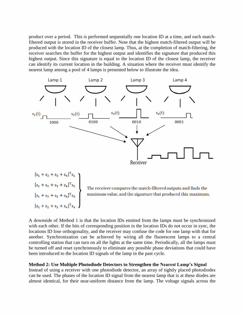
product over a period. This is performed sequentially one location ID at a time, and each match-
filtered output is stored in the receiver buffer. Note that the highest match-filtered output will be
produced with the location ID of the closest lamp. Thus, at the completion of match-filtering, the
receiver searches the buffer for the highest output and identifies the signature that produced this
highest output. Since this signature is equal to the location ID of the closest lamp, the receiver
can identify its current location in the building. A situation where the receiver must identify the
nearest lamp among a pool of 4 lamps is presented below to illustrate the idea.
A downside of Method 1 is that the location IDs emitted from the lamps must be synchronized
with each other. If the bits of corresponding position in the location IDs do not occur in sync, the
locations ID lose orthogonality, and the receiver may confuse the code for one lamp with that for
another. Synchronization can be achieved by wiring all the fluorescent lamps to a central
controlling station that can turn on all the lights at the same time. Periodically, all the lamps must
be turned off and reset synchronously to eliminate any possible phase deviations that could have
been introduced to the location ID signals of the lamp in the past cycle.
Method 2: Use Multiple Photodiode Detectors to Strengthen the Nearest Lamp’s Signal
Instead of using a receiver with one photodiode detector, an array of tightly placed photodiodes
can be used. The phases of the location ID signal from the nearest lamp that is at these diodes are
almost identical, for their near-uniform distance from the lamp. The voltage signals across the
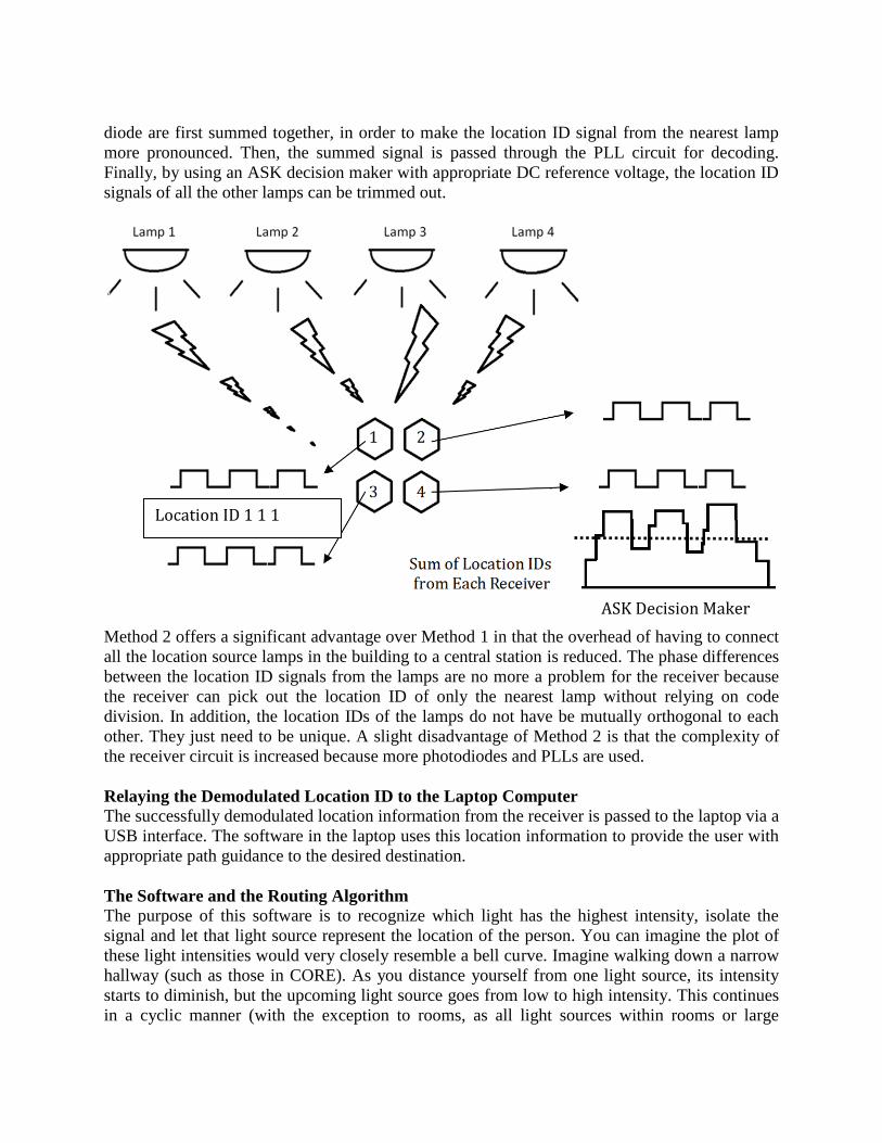
diode are first summed together, in order to make the location ID signal from the nearest lamp
more pronounced. Then, the summed signal is passed through the PLL circuit for decoding.
Finally, by using an ASK decision maker with appropriate DC reference voltage, the location ID
signals of all the other lamps can be trimmed out.
Method 2 offers a significant advantage over Method 1 in that the overhead of having to connect
all the location source lamps in the building to a central station is reduced. The phase differences
between the location ID signals from the lamps are no more a problem for the receiver because
the receiver can pick out the location ID of only the nearest lamp without relying on code
division. In addition, the location IDs of the lamps do not have be mutually orthogonal to each
other. They just need to be unique. A slight disadvantage of Method 2 is that the complexity of
the receiver circuit is increased because more photodiodes and PLLs are used.
Relaying the Demodulated Location ID to the Laptop Computer
The successfully demodulated location information from the receiver is passed to the laptop via a
USB interface. The software in the laptop uses this location information to provide the user with
appropriate path guidance to the desired destination.
The Software and the Routing Algorithm
The purpose of this software is to recognize which light has the highest intensity, isolate the
signal and let that light source represent the location of the person. You can imagine the plot of
these light intensities would very closely resemble a bell curve. Imagine walking down a narrow
hallway (such as those in CORE). As you distance yourself from one light source, its intensity
starts to diminish, but the upcoming light source goes from low to high intensity. This continues
in a cyclic manner (with the exception to rooms, as all light sources within rooms or large
ASK Decision Maker
Location ID 1 1 1

chambers will only exhibit one LID). That is to say, the light nearest to the diode will have the
highest intensity.
A microcontroller will be connected to an omni-directional photodiode, which will be exposed to
all light sources within an average of 25 feet. This microcontroller will act as a receiver, and will
be connected to a device (laptop, handheld controller, etc.) via Serial or USB. We will most
likely implement this receiver using the Arduino, as the freedom of customization fits our needs
perfectly, and that the data, for initial test purposes, is to be uploaded via serial connection onto a
terminal. I assume the output would resemble a continuous loop of interleaved messages
pertaining to the LID and the intensity corresponding to that light – this is due to the fact that all
light sources are constantly transmitting their LIDs and the controller can only capture them one
at a time. To achieve higher efficiency, modifications will need to be made to the wiring.c and
timer.c modules (part of Arduino’s main library) so that signals are not lost, and that the inputs
are synced so that the controller does not become overburdened. As an extension to this, the
receiver can also mount a wireless transmitter (Xbee shield) so that a physical connection need
not be necessary. Of course, this would require the software to include a packet capture utility.
When the light’s Location Identifier is known, it will be compared with a list of values stored
inside a database which points to its location on a map of the building (if the light codes need to
be changed, the entire map does not need to be redesigned). The database may just be a text file
corresponding the lights with the ID it transmits, and the map can be pre-installed or it can be
acquired over the network. A background algorithm uses this location ID to find the shortest
route to the destination – the shortest route is important as in the case of emergencies, as one
must be able to navigate to the nearest exit when they do not know the structure of the
building/floor. A graph traversal algorithm such as Dijkstra’s algorithm solves this issue, as its
main purpose is to find the shortest aggregate distance that needs to be traveled in order to arrive
at a particular destination (in the fastest amount of time, where the ―nodes‖ are in no particular
order, and distances are strictly positive).

The algorithm starts at the initial light source (source node) and arrives at the destination light
source (destination node) in a step-by-step manner, effectively building a shortest path in
increments as it progresses. Each node in the graph is seen as a stop, and the distances between
them (weighted edges) is seen as a step. From source to destination, there’s an alternating
sequence of steps and stops in between, and at each stop, the algorithm looks ahead (visit) to
examine all the possible directions that are traversable. The smallest distance is visited, and then
observes the distances from this node (and an already visited node is removed from the list so it
is not revisited). This idea is applied to every subsequent node until the destination node is
reached. Since the shortest path is taken upon every visit, the final path is almost surely going to
be the shortest route. In a repetitive manner, the shortest distance is always taken. In this case,
the problem of equidistant routes is also ignored, and the runtime is exclusively dependent on the
total number of nodes that can be seen. Dijkstra’s is also fairly quick in computation, even for a
large number of light sources, so the wait/hang time would be negligible. The path will then be
drawn so that the viewer can understand the building structure and feel comfortable with the
route (and the path may or may not change if the person relocates). Below is a diagram (not
drawn to scale) with a table of route calculations:
Step Pick D[B] D[C] D[D] D[E] D[F]
1 A
(source) 3 5 ∞ ∞ ∞
2 B 5 5 ∞ ∞
3 D min(5,15) 30 9
4 C 15 15 ∞
5 E min(9,20)
6 F
7. Demonstration of the Technology
The technology will be demonstrated by retrofitting an area on a single floor of the CORE
building on the Busch campus with the fluorescent navigation system. The ballasts of the
fluorescent lamps in the designated area will be replaced with the new electronic ballasts that are
customized to perform FSK modulation. The area will be mapped out by assigning each
fluorescent lamp with the new ballast a unique location ID. Then, two points in the area will be
3
2
4
5
10
15
12

selected, and the navigation system will be forced to guide a person holding the constructed
receiver system from Point A to Point B.
8. Cost of the Project
The following table identifies electrical parts, equipments, and all other potential sources of
expenses that are necessary to pursue the project from the initial conception to its demonstration.
Type of Expense # Units Required Price/Unit
PLL IC Equal to the # of the photodiodes used in the
receiver Free
CDMA IC Equal to the # of the fluorescent lamps to be
converted to location sources $2.00
Electronic Ballast Equal to the # of the fluorescent lamps to be
converted to location sources $25.00
Microcontroller that
relays location ID to
the laptop via USB
Equal to the # of fluorescent lamps to be
converted to location sources < $30.00
Total: ~ $57.00