Columbia Concrete Products MODEL 16/1600 BLOCK...
34
Columbia Concrete Products 100-18-2 Rev. Page 38 4-08 MODEL 16/1600 BLOCK MACHINE CAUTION HEIGHT CHANGE REQUIREMENTS & MISC. ADJUSTMENTS Stops and spacer requirements: If the replacement mold is of a different height, spacers and stops on the machine must be exchanged and other machine adjustments must be performed as defined in the following procedures. If the change requires removal of stripper beam stops and lowering of the stripper beam, it may be necessary to lower the pallet feeder assembly first to prevent damage to the front hook assembly located on the front of the pallet feeder. Single push pallet feeders are not affected when lowering the stripper beam. Refer to pallet table height adjustment, pallet feeder height adjustment. The stripper rotary valve must also be adjusted to the height selected. (See applicable section.) Figure 22, New Style Pallet Feeder (Single Push Pallet Feeder) Figure 23, Old Style Pallet Feeder
Transcript of Columbia Concrete Products MODEL 16/1600 BLOCK...
Columbia Concrete Products
100-18-2 Rev. Page 38 4-08
MODEL 16/1600 BLOCK MACHINE
CAUTION
HEIGHT CHANGE REQUIREMENTS & MISC. ADJUSTMENTS
Stops and spacer requirements:
If the replacement mold is of a different height, spacers and stops on the machine
must be exchanged and other machine adjustments must be performed as defined
in the following procedures.
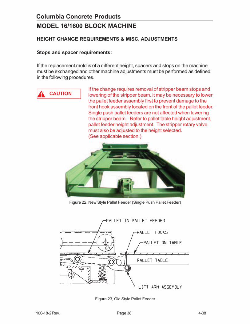
If the change requires removal of stripper beam stops and
lowering of the stripper beam, it may be necessary to lower
the pallet feeder assembly first to prevent damage to the
front hook assembly located on the front of the pallet feeder.
Single push pallet feeders are not affected when lowering
the stripper beam. Refer to pallet table height adjustment,
pallet feeder height adjustment. The stripper rotary valve
must also be adjusted to the height selected.
(See applicable section.)
Figure 22, New Style Pallet Feeder (Single Push Pallet Feeder)
Figure 23, Old Style Pallet Feeder
Columbia Concrete Products
4-08 Page 39 100-18-2 Rev.
MODEL 16/1600 BLOCK MACHINE
Block Machine Spacer Determination:
For ease of use, Columbia supplies a list of spacer setups for common mold
heights. However, the need may arise to determine spacer settings for a unique
mold. Machines spacer settings may be determined using the following directions.
It is assumed that the correct mold assembly, head assembly, and head spacer are
already installed.
Be aware not to lower the pallet table below the level of the
pallet feeder while determining spacer settings or damage
may result to some machine parts at the front hook
assembly.
Compression Beam Spacers:
• Lower compression beam to the down positions.
• The bottom of the mold shoes should protrude through the bottom of the mold
by half their thickness. If the shoes protrude beyond half, you will need to add
enough spacers to make up the difference. If the shoes protrude less than
half, you will need to remove enough spacers to make up the difference.
Figure 21
Pallet Table Spacers:
• Install the lowest pallet table spacer setting for your machine (1/4" for 1600,
¾” for 16).
• Raise the stripper beam to the up position.
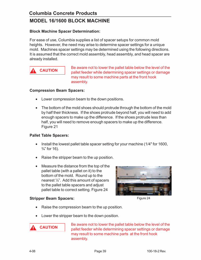
• Measure the distance from the top of the
pallet table (with a pallet on it) to the
bottom of the mold. Round up to the
nearest ¼”. Add this amount of spacers
to the pallet table spacers and adjust
pallet table to correct setting. Figure 24
Stripper Beam Spacers:
• Raise the compression beam to the up position.
• Lower the stripper beam to the down position.
Be aware not to lower the pallet table below the level of the
pallet feeder while determining spacer settings or damage
may result to some machine parts at the front hook
assembly.
CAUTION
CAUTION
Figure 24
Columbia Concrete Products
100-18-2 Rev. Page 40 4-08
MODEL 16/1600 BLOCK MACHINE
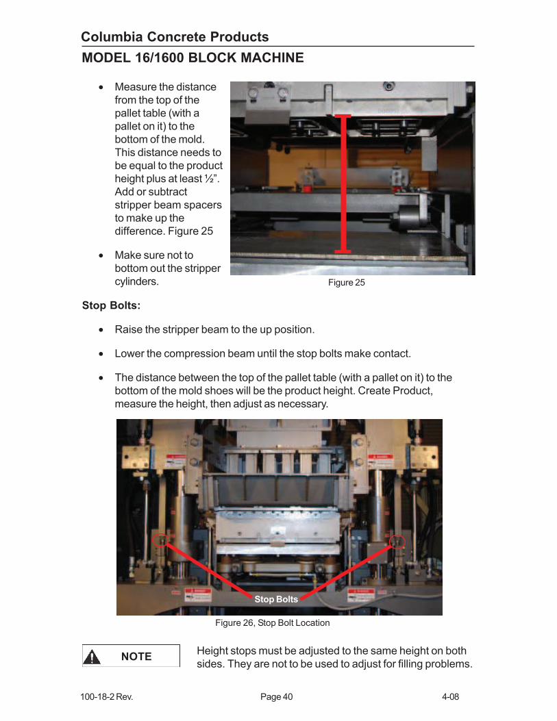
• Measure the distance
from the top of the
pallet table (with a
pallet on it) to the
bottom of the mold.
This distance needs to
be equal to the product
height plus at least ½”.
Add or subtract
stripper beam spacers
to make up the
difference. Figure 25
• Make sure not to
bottom out the stripper
cylinders.
Stop Bolts:
• Raise the stripper beam to the up position.
• Lower the compression beam until the stop bolts make contact.
• The distance between the top of the pallet table (with a pallet on it) to the
bottom of the mold shoes will be the product height. Create Product,
measure the height, then adjust as necessary.
Stop Bolts
Figure 25
Figure 26, Stop Bolt Location
Height stops must be adjusted to the same height on both
sides. They are not to be used to adjust for filling problems.NOTE
Columbia Concrete Products
4-08 Page 41 100-18-2 Rev.
MODEL 16/1600 BLOCK MACHINE
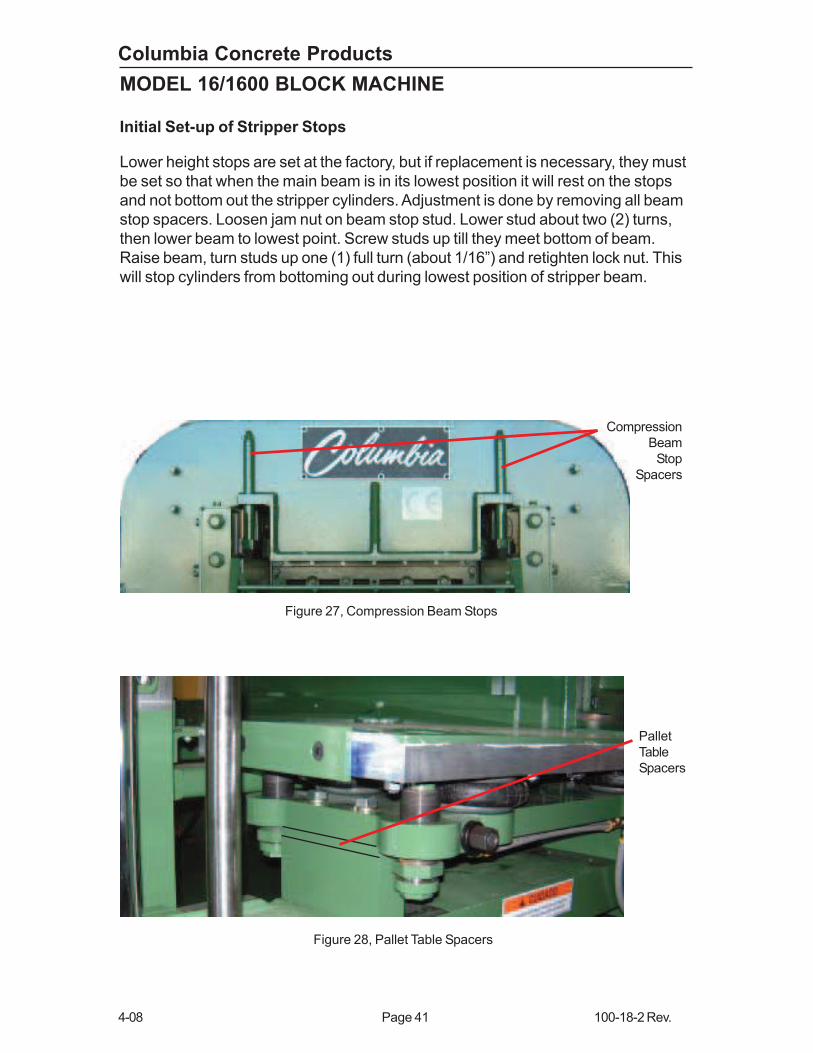
Initial Set-up of Stripper Stops
Lower height stops are set at the factory, but if replacement is necessary, they must
be set so that when the main beam is in its lowest position it will rest on the stops
and not bottom out the stripper cylinders. Adjustment is done by removing all beam
stop spacers. Loosen jam nut on beam stop stud. Lower stud about two (2) turns,
then lower beam to lowest point. Screw studs up till they meet bottom of beam.
Raise beam, turn studs up one (1) full turn (about 1/16”) and retighten lock nut. This
will stop cylinders from bottoming out during lowest position of stripper beam.
Compression
Beam
Stop
Spacers
Pallet
Table
Spacers
Figure 27, Compression Beam Stops
Figure 28, Pallet Table Spacers

Columbia Concrete Products
100-18-2 Rev. Page 42 4-08
MODEL 16/1600 BLOCK MACHINE
The table on page 55 defines spacer and stop requirements in relation to block
height. Figures 31 through 42 show installation requirements. The various height
dimensions given may be made up by adding or subtracting stops and spacers as
required. Various retaining hardware lengths are provided for installation of
different size pallet table spacers.
Rotary Valve Adjustment
Top Cam Only
Stripper
Beam
Stops
Spacers
Figure 29
Figure 30

Columbia Concrete Products
4-08 Page 43 100-18-2 Rev.
MODEL 16/1600 BLOCK MACHINE
HEADRUBBER PAD
PALLET TABLE
STRIPPER BEAM STOP FOR 12”
BLOCKS
Figure 31, Height Change Spacer/Stop Installation for 16 Block Machines
PALLET HOLDER SPACERS
3/4 - 483.20.9
For 16 Block Machine

Columbia Concrete Products
100-18-2 Rev. Page 44 4-08
MODEL 16/1600 BLOCK MACHINE
HEAD RUBBER PAD &
SPACERS
STRIPPER BEAM
STOP SPACER
PART NO. 931.5
FOR 10” BLOCKS
2
Figure 32, Height Change Spacer/Stop Installation for 16 Block Machines
PALLET TABLE
PALLET HOLDER SPACERS
3/4 - 483.20.9
2 - 483.1.317
For 16 Block Machine
Columbia Concrete Products
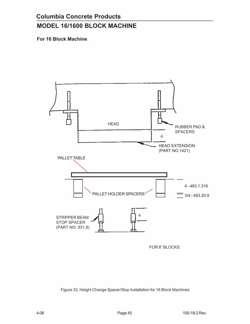
4-08 Page 45 100-18-2 Rev.
MODEL 16/1600 BLOCK MACHINE
HEAD EXTENSION
(PART NO.1421)
RUBBER PAD &
SPACERS
HEAD
STRIPPER BEAM
STOP SPACER
(PART NO. 931.8)
FOR 8” BLOCKS
4
4
Figure 33, Height Change Spacer/Stop Installation for 16 Block Machines
PALLET TABLE
PALLET HOLDER SPACERS 3/4 - 483.20.9
4 - 483.1.316
For 16 Block Machine

Columbia Concrete Products
100-18-2 Rev. Page 46 4-08
MODEL 16/1600 BLOCK MACHINE
RUBBER PAD &
SPACERSHEAD
HEAD EXTENSION
(PART NO. 1421)
4
FOR 6” BLOCKS
STRIPPER BEAM
STOP SPACER
(PART NO. 931.8)
2
4
(PART NO. 931.5)
Figure 34, Height Change Spacer/Stop Installation for 16 Block Machine
PALLET TABLE
PALLET HOLDER SPACERS3/4 - 483.20.9
4 - 483.1.316
2 - 483.1.317
For 16 Block Machine
Columbia Concrete Products
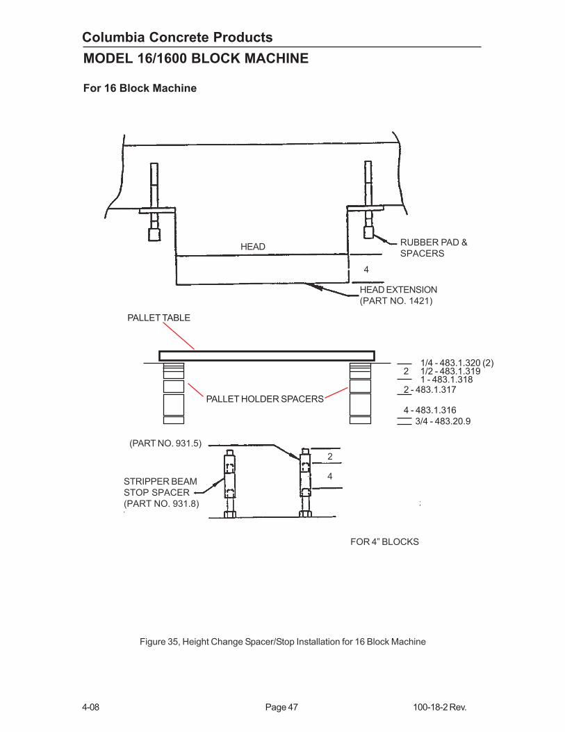
4-08 Page 47 100-18-2 Rev.
MODEL 16/1600 BLOCK MACHINE
HEAD RUBBER PAD &
SPACERS
4
HEAD EXTENSION
(PART NO. 1421)
(PART NO. 931.5)
STRIPPER BEAM
STOP SPACER
(PART NO. 931.8)
2
4
FOR 4” BLOCKS
Figure 35, Height Change Spacer/Stop Installation for 16 Block Machine
PALLET TABLE
PALLET HOLDER SPACERS
3/4 - 483.20.9
4 - 483.1.316
2 - 483.1.317
1/4 - 483.1.320 (2)2 1/2 - 483.1.319
1 - 483.1.318
For 16 Block Machine

Columbia Concrete Products
100-18-2 Rev. Page 48 4-08
MODEL 16/1600 BLOCK MACHINE
HEAD RUBBER PAD &
SPACERS
4
STRIPPER BEAM
STOP SPACER
(PART NO. 931.8)
FOR 2” BLOCKS
4
Figure 36, Height Change Spacer/Stop Installation for 16 Block Machines
For 16 Block Machine
PALLET TABLE
PALLET HOLDER SPACERS
3/4 - 483.20.9
4 - 483.1.316
4 - 483.1.316
1/4 - 483.1.320 (2)2 1/4 1/2 - 483.1.319
1 - 483.1.318
HEAD EXTENSION
PART NO. (1421)

Columbia Concrete Products
4-08 Page 49 100-18-2 Rev.
MODEL 16/1600 BLOCK MACHINE
HEADRUBBER PAD
PALLET TABLE
STRIPPER BEAM STOP FOR 12”
BLOCKS
Figure 37, Height Change Spacer/Stop Installation for 1600 Block Machines
PALLET HOLDER SPACERS
1/4 - 483.1.320
For 1600 Block Machine
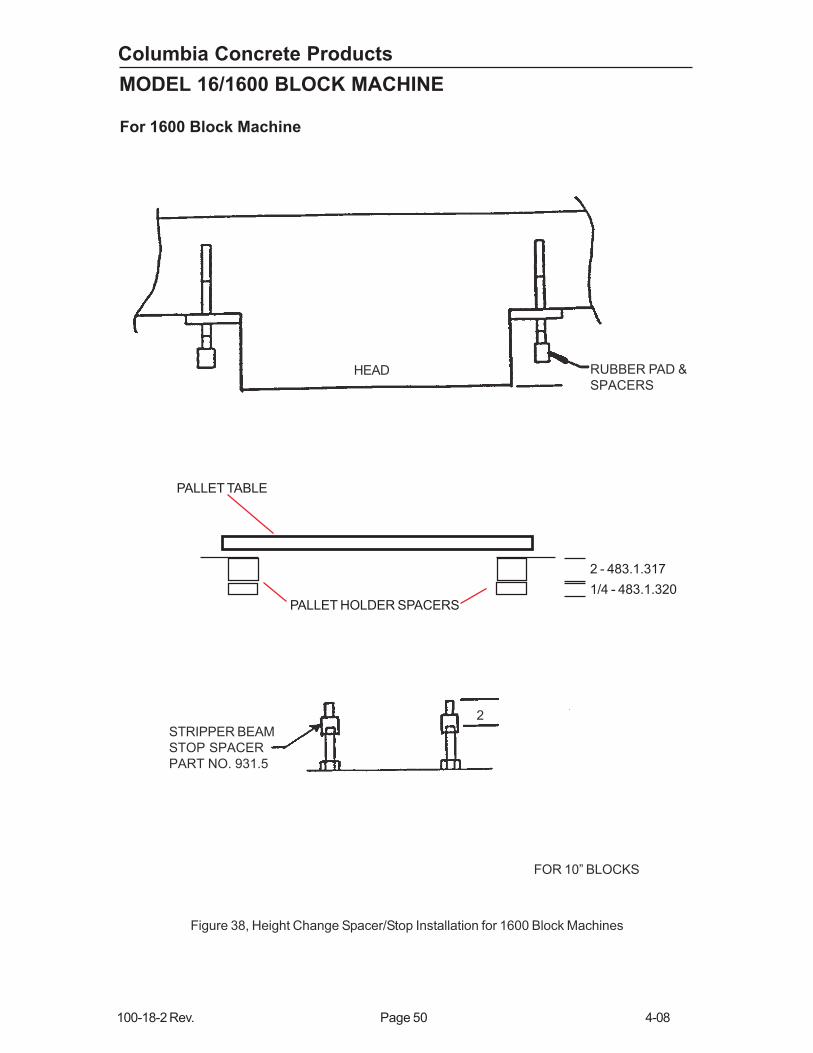
Columbia Concrete Products
100-18-2 Rev. Page 50 4-08
MODEL 16/1600 BLOCK MACHINE
HEAD RUBBER PAD &
SPACERS
STRIPPER BEAM
STOP SPACER
PART NO. 931.5
FOR 10” BLOCKS
2
Figure 38, Height Change Spacer/Stop Installation for 1600 Block Machines
PALLET TABLE
PALLET HOLDER SPACERS
1/4 - 483.1.320
2 - 483.1.317
For 1600 Block Machine
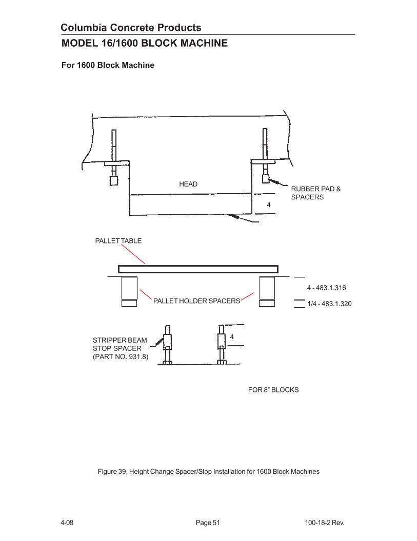
Columbia Concrete Products
4-08 Page 51 100-18-2 Rev.
MODEL 16/1600 BLOCK MACHINE
Figure 39, Height Change Spacer/Stop Installation for 1600 Block Machines
RUBBER PAD &
SPACERS
HEAD
STRIPPER BEAM
STOP SPACER
(PART NO. 931.8)
FOR 8” BLOCKS
4
4
PALLET TABLE
PALLET HOLDER SPACERS 1/4 - 483.1.320
4 - 483.1.316
For 1600 Block Machine
Columbia Concrete Products
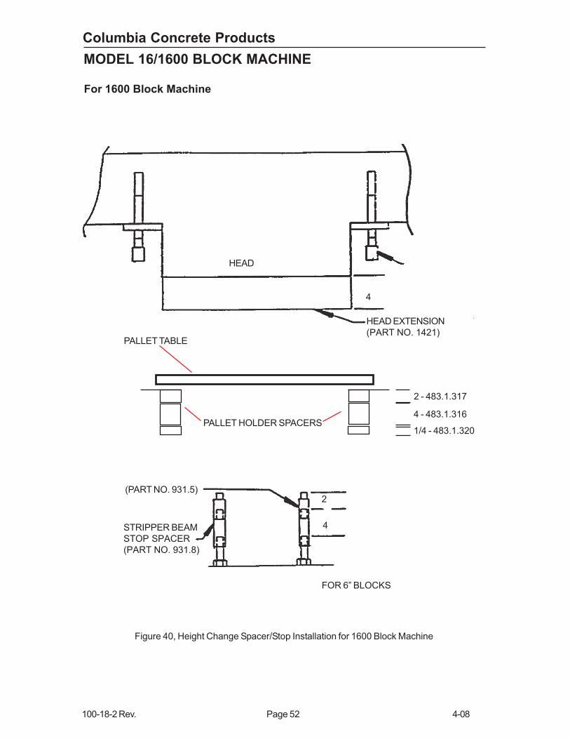
100-18-2 Rev. Page 52 4-08
MODEL 16/1600 BLOCK MACHINE
HEAD
HEAD EXTENSION
(PART NO. 1421)
4
FOR 6” BLOCKS
STRIPPER BEAM
STOP SPACER
(PART NO. 931.8)
2
4
(PART NO. 931.5)
Figure 40, Height Change Spacer/Stop Installation for 1600 Block Machine
PALLET TABLE
PALLET HOLDER SPACERS1/4 - 483.1.320
4 - 483.1.316
2 - 483.1.317
For 1600 Block Machine
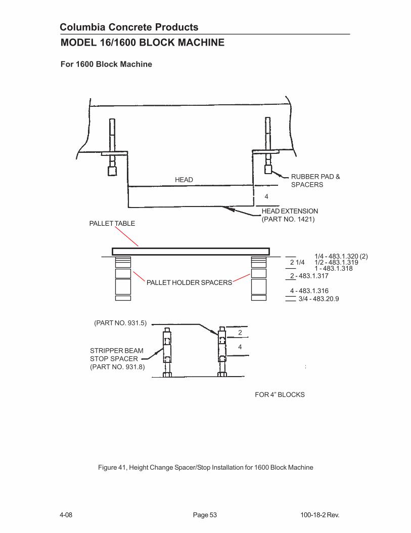
Columbia Concrete Products
4-08 Page 53 100-18-2 Rev.
MODEL 16/1600 BLOCK MACHINE
HEAD RUBBER PAD &
SPACERS
4
(PART NO. 931.5)
STRIPPER BEAM
STOP SPACER
(PART NO. 931.8)
2
4
FOR 4” BLOCKS
Figure 41, Height Change Spacer/Stop Installation for 1600 Block Machine
For 1600 Block Machine
PALLET TABLE
PALLET HOLDER SPACERS
3/4 - 483.20.9
4 - 483.1.316
2 - 483.1.317
1/4 - 483.1.320 (2)2 1/4 1/2 - 483.1.319
1 - 483.1.318
HEAD EXTENSION
(PART NO. 1421)

Columbia Concrete Products
100-18-2 Rev. Page 54 4-08
MODEL 16/1600 BLOCK MACHINE
HEAD RUBBER PAD &
SPACERS
4
STRIPPER BEAM
STOP SPACER
(PART NO. 931.8)
FOR 2” BLOCKS
4
Figure 42, Height Change Spacer/Stop Installation for 1600 Block Machines
PALLET TABLE
PALLET HOLDER SPACERS
3/4 - 483.20.9
4 - 483.1.316
4 - 483.1.316
1/4 - 483.1.320 (2)2 1/4 1/2 - 483.1.319
1 - 483.1.318
HEAD EXTENSION
PART NO. (1421)
For 1600 Block Machine
Columbia Concrete Products
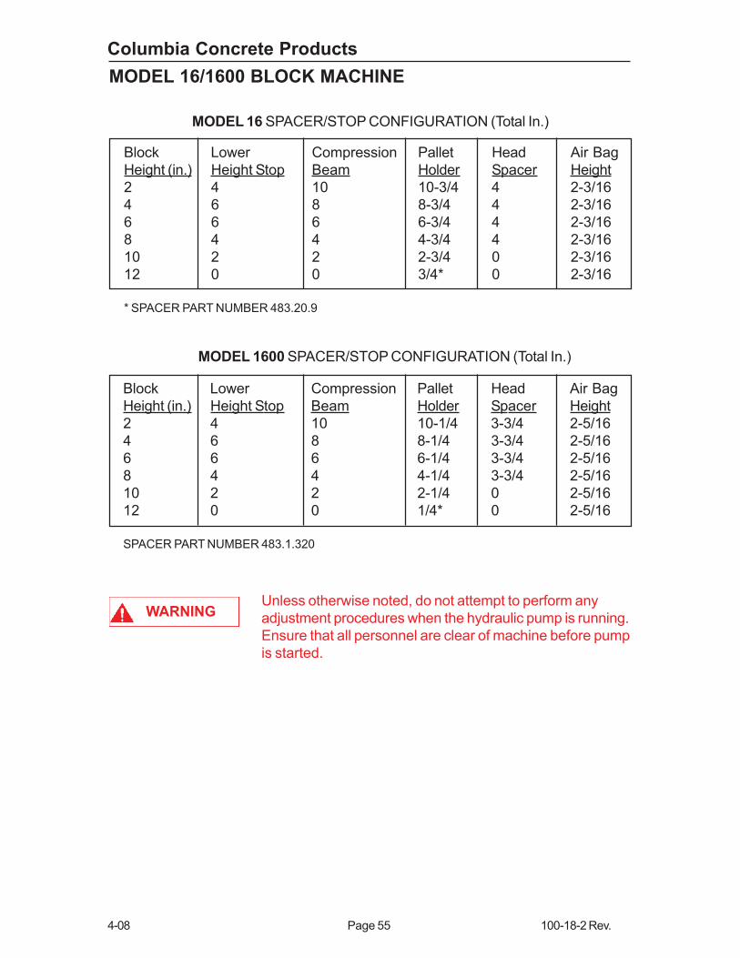
4-08 Page 55 100-18-2 Rev.
MODEL 16/1600 BLOCK MACHINE
MODEL 16 SPACER/STOP CONFIGURATION (Total In.)
Unless otherwise noted, do not attempt to perform any
adjustment procedures when the hydraulic pump is running.
Ensure that all personnel are clear of machine before pump
is started.
Block Lower Compression Pallet Head Air Bag
Height (in.) Height Stop Beam Holder Spacer Height
2 4 10 10-3/4 4 2-3/16
4 6 8 8-3/4 4 2-3/16
6 6 6 6-3/4 4 2-3/16
8 4 4 4-3/4 4 2-3/16
10 2 2 2-3/4 0 2-3/16
12 0 0 3/4* 0 2-3/16
* SPACER PART NUMBER 483.20.9
MODEL 1600 SPACER/STOP CONFIGURATION (Total In.)
Block Lower Compression Pallet Head Air Bag
Height (in.) Height Stop Beam Holder Spacer Height
2 4 10 10-1/4 3-3/4 2-5/16
4 6 8 8-1/4 3-3/4 2-5/16
6 6 6 6-1/4 3-3/4 2-5/16
8 4 4 4-1/4 3-3/4 2-5/16
10 2 2 2-1/4 0 2-5/16
12 0 0 1/4* 0 2-5/16
SPACER PART NUMBER 483.1.320
WARNING
Columbia Concrete Products
100-18-2 Rev. Page 56 4-08
MODEL 16/1600 BLOCK MACHINE
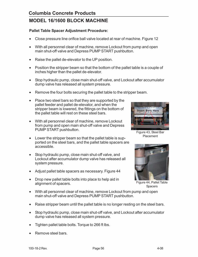
Pallet Table Spacer Adjustment Procedure:
• Close pressure line orifice ball valve located at rear of machine. Figure 12
• With all personnel clear of machine, remove Lockout from pump and openmain shut-off valve and Depress PUMP START pushbutton.
• Raise the pallet de-elevator to the UP position.
• Position the stripper beam so that the bottom of the pallet table is a couple ofinches higher than the pallet de-elevator.
• Stop hydraulic pump, close main shut-off valve, and Lockout after accumulatordump valve has released all system pressure.
• Remove the four bolts securing the pallet table to the stripper beam.
• Place two steel bars so that they are supported by thepallet feeder and pallet de-elevator, and when thestripper beam is lowered, the fittings on the bottom ofthe pallet table will rest on these steel bars.
• With all personnel clear of machine, remove Lockoutfrom pump and open main shut-off valve and DepressPUMP START pushbutton.
• Lower the stripper beam so that the pallet table is sup-ported on the steel bars, and the pallet table spacers areaccessible.
• Stop hydraulic pump, close main shut-off valve, andLockout after accumulator dump valve has released allsystem pressure.
• Adjust pallet table spacers as necessary. Figure 44
• Drop new pallet table bolts into place to help aid inalignment of spacers.
• With all personnel clear of machine, remove Lockout from pump and openmain shut-off valve and Depress PUMP START pushbutton.
• Raise stripper beam until the pallet table is no longer resting on the steel bars.
• Stop hydraulic pump, close main shut-off valve, and Lockout after accumulatordump valve has released all system pressure.
• Tighten pallet table bolts. Torque to 266 ft lbs.
• Remove steel bars.
Figure 44, Pallet Table
Spacers
Insert Bars Here
Figure 43, Steel Bar
Placement

Columbia Concrete Products
4-08 Page 57 100-18-2 Rev.
MODEL 16/1600 BLOCK MACHINE
STRIPPER BEAM SPACER
LOWER HEIGHT STOP
LOCK NUT
Figure 45, Typical Lower Spacer Installation
Lower Height Stop Adjustment Procedures
To set the stops, loosen the stop locknuts and turn stops down below main beam. Run
the main beam down as far as it will go, bottoming out the cylinders. At this point, turn
the stops up until they make contact with the main beam. Run the main beam up, then
raise the stops up one complete turn of the threads and lock in place. This procedure
will assure that the stripper cylinders do not bottom out by approximately 1/16 inch.
After adjustments have been made lower the stripper beam back down against stops,
Using a measuring tape measure from the base of the machine flat clean surface
where the stripper cylinders bolts down to the top of the stripper beam on both sides.
The dimension should be the same. If this dimension is off by more then 1/32 inch
recheck stop adjustments. To insure beam rest tight against stops raise stripper beam
and install additional 4 inch stops. Lower stripper beam down against stops and
check to see if you can turn either of the additional stops. Again check measurements.
If the beam racks when lowered to the stops, adjustments must be made or inspection
of stops being used (if worn out call Columbia for replacements to avoid damage) to
insure beam sets on stops without racking beam from side to side as this will cause
premature failure of stripper rod seals, column bracket seals, main guide bar bushings,
and set up problems with the pallet table.
Measure
Here
Columbia Concrete Products
100-18-2 Rev. Page 58 4-08
MODEL 16/1600 BLOCK MACHINE
ROTARY VALVE
CONTROL CAM
CAM RETAINING SCREW
MAIN
BEAM
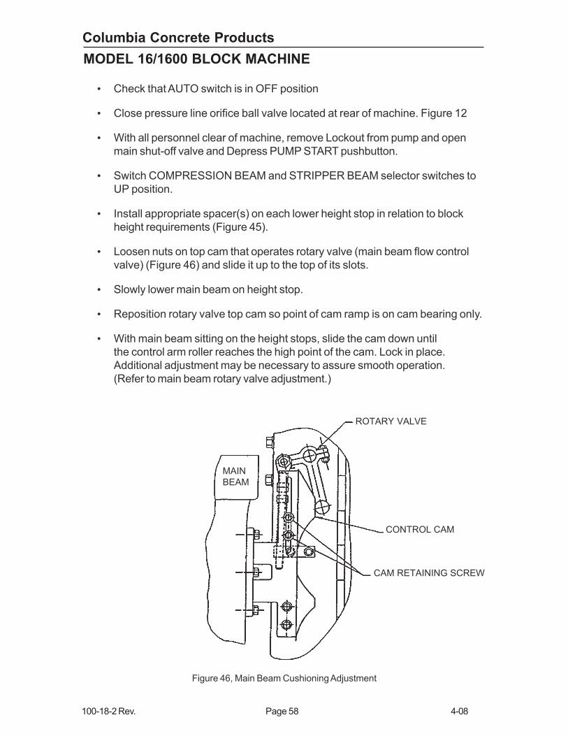
Figure 46, Main Beam Cushioning Adjustment
• Check that AUTO switch is in OFF position
• Close pressure line orifice ball valve located at rear of machine. Figure 12
• With all personnel clear of machine, remove Lockout from pump and open
main shut-off valve and Depress PUMP START pushbutton.
• Switch COMPRESSION BEAM and STRIPPER BEAM selector switches to
UP position.
• Install appropriate spacer(s) on each lower height stop in relation to block
height requirements (Figure 45).
• Loosen nuts on top cam that operates rotary valve (main beam flow control
valve) (Figure 46) and slide it up to the top of its slots.
• Slowly lower main beam on height stop.
• Reposition rotary valve top cam so point of cam ramp is on cam bearing only.
• With main beam sitting on the height stops, slide the cam down until
the control arm roller reaches the high point of the cam. Lock in place.
Additional adjustment may be necessary to assure smooth operation.
(Refer to main beam rotary valve adjustment.)

Columbia Concrete Products
4-08 Page 59 100-18-2 Rev.
MODEL 16/1600 BLOCK MACHINE
• As shown on Figure 47, install appropriate compression beam stops in
relation to block height requirements.
Compression beam down motion is controlled by compression beam stops.
Appropriate spacers must be added or removed to allow the compression beam to
lower to the point that the shoes extend to the bottom of the mold half shoe beyond.
If changing to a shorter mold, spacers must be moved from top to bottom. If
changing to a higher mold, spacers must be moved from bottom to top. The proper
amount of spacers will allow the shoes to extend to the bottom of the mold or half
way beyond when the rubber bumper strikes the top of the feed box frame.
• Set pallet feeder switch so that it is closed when main beam is in full down
position.
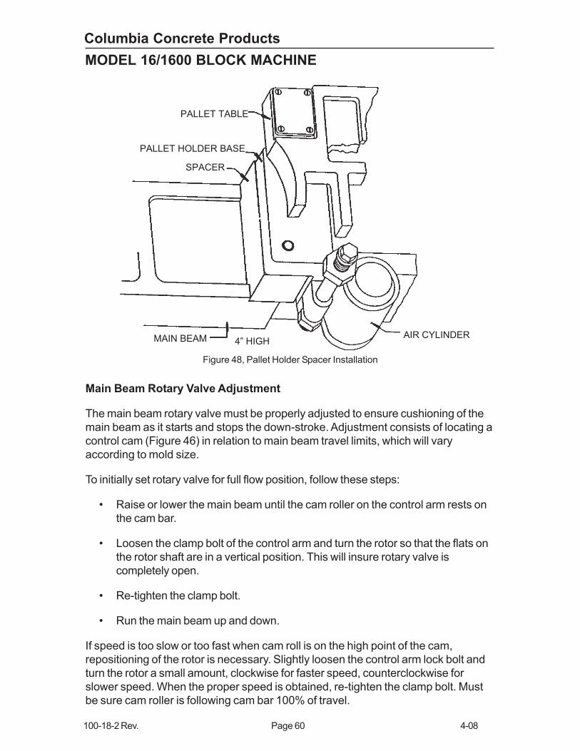
• Install appropriate spacer(s) under each side of pallet table in relation to
block height requirements (Figure 48).
Height spacers on the system conveyor-elevator must also
be changed to correspond to pallet table height.NOTE
RUBBER BUM
PER
COMPRESSIO
N BEAM
STOP
FEED BOX
FRAME
SPACERSHEX HEAD N
UT
COMPRESSION BEAM
ASSEMBLY
Figure 47, Typical Compression Beam Stop Installation
Columbia Concrete Products
100-18-2 Rev. Page 60 4-08
MODEL 16/1600 BLOCK MACHINE
Main Beam Rotary Valve Adjustment
The main beam rotary valve must be properly adjusted to ensure cushioning of the
main beam as it starts and stops the down-stroke. Adjustment consists of locating a
control cam (Figure 46) in relation to main beam travel limits, which will vary
according to mold size.
To initially set rotary valve for full flow position, follow these steps:
• Raise or lower the main beam until the cam roller on the control arm rests on
the cam bar.
• Loosen the clamp bolt of the control arm and turn the rotor so that the flats on
the rotor shaft are in a vertical position. This will insure rotary valve is
completely open.
• Re-tighten the clamp bolt.
• Run the main beam up and down.
If speed is too slow or too fast when cam roll is on the high point of the cam,
repositioning of the rotor is necessary. Slightly loosen the control arm lock bolt and
turn the rotor a small amount, clockwise for faster speed, counterclockwise for
slower speed. When the proper speed is obtained, re-tighten the clamp bolt. Must
be sure cam roller is following cam bar 100% of travel.
Figure 48, Pallet Holder Spacer Installation
PALLET TABLE
PALLET HOLDER BASE
SPACER
MAIN BEAM 4” HIGHAIR CYLINDER
Columbia Concrete Products
4-08 Page 61 100-18-2 Rev.
MODEL 16/1600 BLOCK MACHINE
Advanced Spacer Method:
If you constantly change between two or more block heights, you can manipulate the
spacers in a way that you do not need to change the pallet feeder height. The down
side of this is that when running the shorter product, there is a longer strip cycle
which can greatly cut into your productive output. This page will help you determine
how to set up your spacers for this, and if it will save you time or not.
There is one condition that needs to be met if you would like to try this method for a
16/1600:
The sum of the larger product height plus the difference of the product
heights cannot be greater than 12.
Example 1: If you want to go back and forth between an 8" and a 4" block.
8+(8-4)=8+4=12
This combination will work.
Example 2: If you want to go back and forth between an 8" and a 2" block.
8+(8-2)=8+6=14
This combination will NOT work.
Follow these steps to setup your 16/1600 block machine:
1. Set the machine up for the taller product as usual.
2. Now change to the shorter product mold/head assembly.
3. Set the compression beam spacers and pallet table spacers as usual for the
shorter product.
4. Lower the stripper beam to the down position.
5. Measure the distance between the top of the pallet table (with a pallet on it)
to the top of the pallet feeder (with a pallet on it).
6. Remove this amount from the stripper beam spacers.
You may need to modify a standard Columbia Machine Inc.
spacer to obtain your exact requirements.NOTE
Columbia Concrete Products
100-18-2 Rev. Page 62 4-08
MODEL 16/1600 BLOCK MACHINE
To determine if you will save time with this method, you need to run this calculation:
Tc=(Tf * Vsmax * Tcyc) / (60 * Hd)
Hd (in) = The difference in height of the two products
Vsmax (in/sec) = Maximum stripper speed. 10-15in/sec would be a reasonable number, but
due to setup variations, you will need to measure this for the most accurate calculation.
Tcyc (sec/cyc)= Average block machine cycle time of the shorter product
Tf (min) = Time to change the pallet feeder height (remember you have already
changed the compression beam spacers, proximity switch flags, and table spacers, so
this is ONLY the time associated with the pallet feeder height and rotary valve adjustment.)
Tc (hrs) = Given the other four variables, this is the time at which you break even
between using the advanced spacer method vs changing the pallet feeder height. If you
plan to run longer than this time, you should change the pallet feeder height. If you plan to
run shorter than this time, you should use the advanced spacer method.
As an example (using approximate numbers):
Lets say you want to go back and forth between 8" and 4" products on a regular
basis. You will need to know if you should change the pallet table height or if you
should use the advanced spacer method. Your values are as follows:
Hd =(8"-4")=4in
Vsmax =10in/sec
Tcyc =10sec/cyc
Tf =20min
First, determine if this is a valid combination using the condition “The sum of the
larger product height plus the difference of the product heights cannot be greater
than 12”.
8"+(8"-4")=12"
This combination will work. Now calculate the break-even time.
Tc =(20min * 10in/sec * 10sec/cyc) / (60 * 4in)
Tc =8.33hrs
So in this example, the break even time where changing the pallet feeder height
yields the same production as using the advanced spacer method is 8.33 hrs. So if
you are running 8.33 hrs or less of the 4" product before changing back to the 8"
product, you should use the advanced spacer method. Otherwise, you should
change the pallet feeder height.

Columbia Concrete Products
4-08 Page 63 100-18-2 Rev.
MODEL 16/1600 BLOCK MACHINE
NOTE
WARNING
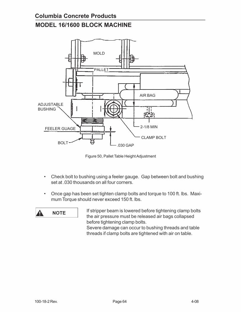
Pallet Table Adjustment
When a new mold is installed, the distance between the pallet table and the mold
must be adjusted to ensure proper pallet clearance is achieved. Two basic pallet
table settings (Tight & Loose) are suggested. (Figure 50).
1. Tight Table Settings (normally used for most products)
Check that pallet table surface is clean, flat and free of all
objects.
• Check that AUTO switch is in OFF position.
• Pallet table AIR switch in AUTO.
• Pallet table air Front Low – 40 psi
• Pallet table air Rear Low – 40 psi
• Switch the manual selector switches in
the sequence noted:
• COMPRESSION BEAM UP
• STRIPPER UP
• PALLET FEEDER BACK
Exercise extreme caution while performing this
adjustment with the pump on.
• Vibrator and mold at top dead center (TDC) counter weights down.
• Place clean flat production pallet on table.
• Check for proper spacers under the pallet saddle as determined by mold
height.
• Manually select STRIPPER UP keep energized holding pallet against mold
slightly depressing air bags.
• With pallet able air switch in AUTO
• Set Low table air at 40 psi Front and Rear.
• With clamp bolts loose, turn adjustable bushings until a gap is obtained
between the head of the pallet table bolt and adjustable bushing.
Figure 49
Columbia Concrete Products
100-18-2 Rev. Page 64 4-08
MODEL 16/1600 BLOCK MACHINE
Figure 50, Pallet Table Height Adjustment
MOLD
PALLET
AIR BAG
2-1/8 MIN
CLAMP BOLT
.030 GAPBOLT
FEELER GUAGE
ADJUSTABLE
BUSHING
NOTE
• Check bolt to bushing using a feeler gauge. Gap between bolt and bushing
set at .030 thousands on all four corners.
• Once gap has been set tighten clamp bolts and torque to 100 ft. lbs. Maxi-
mum Torque should never exceed 150 ft. lbs.
If stripper beam is lowered before tightening clamp bolts
the air pressure must be released air bags collapsed
before tightening clamp bolts.
Severe damage can occur to bushing threads and table
threads if clamp bolts are tightened with air on table.
Columbia Concrete Products
4-08 Page 65 100-18-2 Rev.
MODEL 16/1600 BLOCK MACHINE
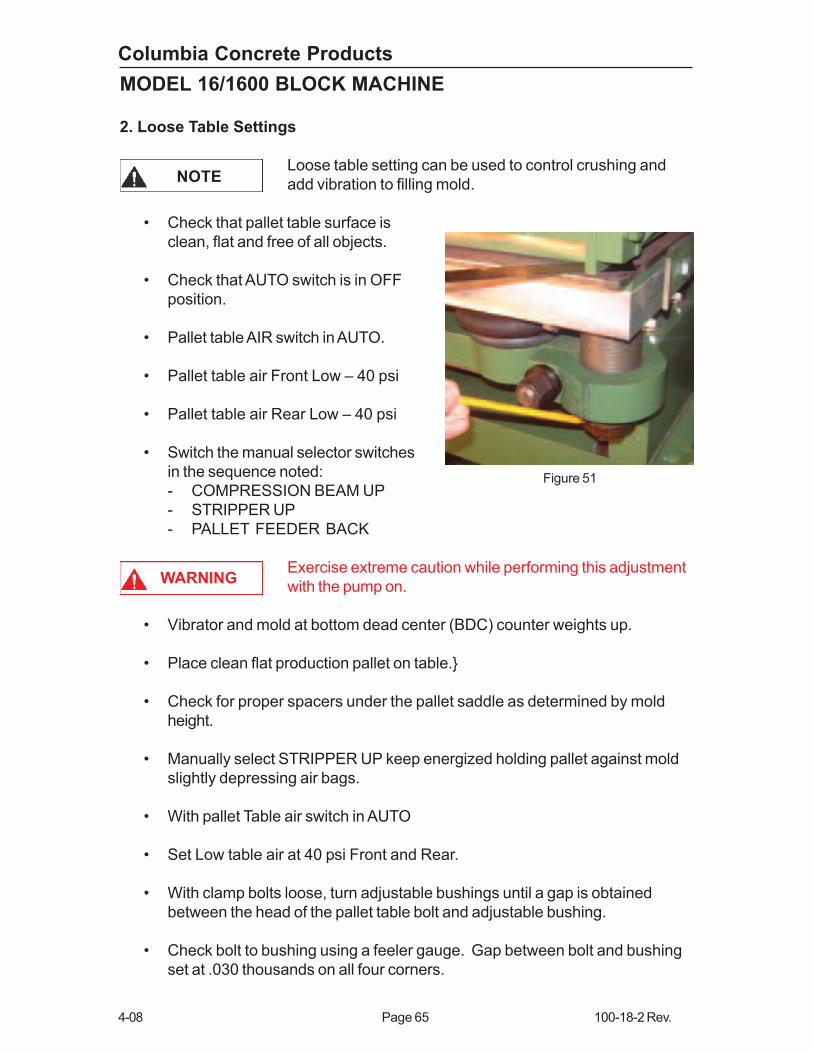
2. Loose Table Settings
Loose table setting can be used to control crushing and
add vibration to filling mold.
• Check that pallet table surface is
clean, flat and free of all objects.
• Check that AUTO switch is in OFF
position.
• Pallet table AIR switch in AUTO.
• Pallet table air Front Low – 40 psi
• Pallet table air Rear Low – 40 psi
• Switch the manual selector switches
in the sequence noted:
- COMPRESSION BEAM UP
- STRIPPER UP
- PALLET FEEDER BACK
Exercise extreme caution while performing this adjustment
with the pump on.
• Vibrator and mold at bottom dead center (BDC) counter weights up.
• Place clean flat production pallet on table.}
• Check for proper spacers under the pallet saddle as determined by mold
height.
• Manually select STRIPPER UP keep energized holding pallet against mold
slightly depressing air bags.
• With pallet Table air switch in AUTO
• Set Low table air at 40 psi Front and Rear.
• With clamp bolts loose, turn adjustable bushings until a gap is obtained
between the head of the pallet table bolt and adjustable bushing.
• Check bolt to bushing using a feeler gauge. Gap between bolt and bushing
set at .030 thousands on all four corners.
NOTE
WARNING
Figure 51
Columbia Concrete Products
100-18-2 Rev. Page 66 4-08
MODEL 16/1600 BLOCK MACHINE
Once gap has been set tighten clamp bolts and torque to 100 ft. lbs. MaximumTorque should never exceed 150 ft. lbs.
If stripper beam is lowered before tightening clamp boltsthe air pressure must be released air bags collapsedbefore tightening clamp bolts. Severe damage can occurto bushing threads and table threads if clamp bolts aretightened with air on table.
Tight Table Settings vs. Loose Table Settings:
Table settings may very depending on the type of material you use and how well itfeeds into the mold.
Tight Table Setting: A tight table setting does not allow the pallet to float between thepallet table and the mold bottom during fill and compression cycle. A gap betweenthe pallet table bolt and bushing is set to keep the pallet tight against the moldbottom. Because the table is set when the mold is in its upper most travel thecounterweights position will be in the down position, the pallet and table will stay incontact with the mold at all times. When the mold travels to its full down position thegap between the bolts and bushings increases by the throw of the vibrator. If thevibrator has .080 thousands throw the gap between the bolt and bushing willincrease by .040 thousands. If it’s .100 thousands throw the gap will increase by.050 thousands.
Example: Using a .080 thousands throw vibrator assembly the mold is in the upposition counterweights in the down position the gap between the bolts andbushings is set at .030 thousands. As the vibrator rotates the mold is moved to itslowest position and the gap now has increased by .080 thousands with a total gapof .110 thousands.
Advantages over loose table settings: By using a tight table setting the bolt andbushing do not come in contact with each other during fill and compression cyclewhich extends the life of the bolt and bushing first by not hammering against eachother and causing scallops to the bolt and bushings and damaging bushing andsaddle threads..
Once the table has been set for a tight table setting we can get the same effect of aloose table by dropping the low table air from 40 to 35 or 30 to allow the pallet torattle between the mold and table giving us the same effect as a loose table butwithout damaging the bolts and bushings. Again this will allow better fill in somecases and helps to evacuate entrapped air from the mold cavity.
Loose Table setting: A loose table setting allows the pallet to float between thepallet and the mold. A loose table also aids with air evacuation and may help to fillthe mold. A loose table setting is set with the mold in the down position,
NOTE

Columbia Concrete Products
4-08 Page 67 100-18-2 Rev.
MODEL 16/1600 BLOCK MACHINE
counterweights in the up position; set the gap between the bolt and bushing at .030thousands. Now when the mold travels up the table will stop moving up once thebolts and bushings make contact but the mold will continue moving up until itreaches the vibrators maximum throw. The gap which was set between the boltsand bushings is now between the pallet and mold. The .030 thousands gapbetween the pallet and mold allows the pallet to rattle during full and compressioncycle. The pallet is only in contact with the bottom of the mold when the mold is in itsfull down position or vibrator throw is at the bottom (BDC).
Example: Using a .80 thousands throw vibrator assembly the mold is in the downposition and counterweights in the up position the gap between the bolts andbushings are set at .030 thousands. As the vibrator rotates .030 the bolts andbushings make contact and therefore the table will not continue to move up with themold. The vibrator continues to rotate an additional .050 thousand and the mold isnow at its highest position. We now have .030 between the pallet and the bottom ofthe mold.
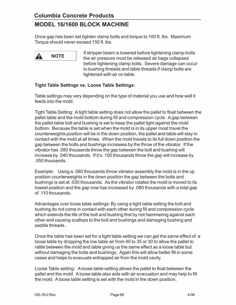
Wear problem: Excessive wear to the bolt and bushing willoccur due to the bolt and bushing coming into contactduring fill and compression cycle using loose setting.
For your specific pallet table settings you may find for some products you like a tighttable setting and others you may require a loose table setting.
Example of Worn Bushing
from Loose Setting
WARNING
Figure 52

Columbia Concrete Products
100-18-2 Rev. Page 68 4-08
MODEL 16/1600 BLOCK MACHINE
PALLET FEED MECHANISM
Pallet feed components serve to receive and transfer pallets to the block-making
section of the machine. Pallets are initially transferred from a pallet storage hopper
by a carriage that is moved forward and backward by a hydraulic cylinder. The
forward and back stroke is controlled through a rotary flow control valve and a flow
control valve located on main manifold for FORWARD. Each pallet is transferred
from the hopper by two pulling dogs that are mechanically positioned during the
forward cycle. The forward movement of the carriage advances the pallets along the
rails with wear strips. Hold down angles or wheels on the pallet feeder prevent
shingling of pallets and ensure correct alignment for entry onto a pallet table in the
block-making section.
The rotary flow control valve is cam-operated to permit variable speed of the pallet
carriage. To prevent cracking of green block caused by sudden jerks or stops, the
carriage movement is slowed at the beginning and end of each transfer stroke.
When changing from one block height to another due to mold changes, a hydraulic
riser cylinder can raise the frame of the pallet feeder to match the new block height
requirements.
As a part of the pallet supply system, cleaned pallets are re-circulated to the block
machine and deposited in the pallet hopper. The bottom pallet in the hopper is then
engaged and carried forward one pallet at a time by puller dogs. At the completion
of a compression period, a clean pallet is then placed on the pallet table, ready for
the next cycle. In the event the pallet hopper has less than three pallets, a proximity
switch is opened to disable automatic machine operation until more pallets are
received.
Pallet Feeder Alignment And Height Adjustment
The proper sequence for changing pallet feeder height
must be followed or damage may result to some machine
parts.
Some models of pallet feeders utilize a front lift arm or a front hook assembly that
contact the pallet table when the stripper beam comes down to the block strip
position.
In this position, the pallet in the pallet feeder is at the same level as the pallet on the
table. When attempting to change to a different height, never run the main beam
down lower than this point, as it will damage the front hook or lift arm assembly (see
Figure 19). Before making a pallet feeder height adjustment, the pallet feeder must
be moved down.
CAUTION
Columbia Concrete Products
4-08 Page 69 100-18-2 Rev.
MODEL 16/1600 BLOCK MACHINE
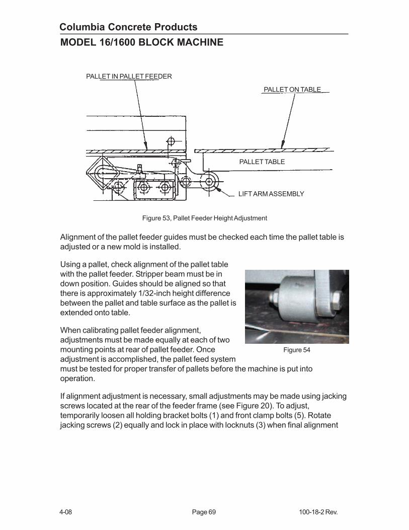
Alignment of the pallet feeder guides must be checked each time the pallet table is
adjusted or a new mold is installed.
Using a pallet, check alignment of the pallet table
with the pallet feeder. Stripper beam must be in
down position. Guides should be aligned so that
there is approximately 1/32-inch height difference
between the pallet and table surface as the pallet is
extended onto table.
When calibrating pallet feeder alignment,
adjustments must be made equally at each of two
mounting points at rear of pallet feeder. Once
adjustment is accomplished, the pallet feed system
must be tested for proper transfer of pallets before the machine is put into
operation.
If alignment adjustment is necessary, small adjustments may be made using jacking
screws located at the rear of the feeder frame (see Figure 20). To adjust,
temporarily loosen all holding bracket bolts (1) and front clamp bolts (5). Rotate
jacking screws (2) equally and lock in place with locknuts (3) when final alignment
PALLET IN PALLET FEEDER
PALLET ON TABLE
PALLET TABLE
LIFT ARM ASSEMBLY
Figure 53, Pallet Feeder Height Adjustment
Figure 54

Columbia Concrete Products
100-18-2 Rev. Page 70 4-08
MODEL 16/1600 BLOCK MACHINE
and testing is complete.
If a major adjustment is required because of a change in the mold height
configuration, additional mounting holes are provided on the clamp bars for
relocation of feeder adjustment brackets. Relocation of the adjustment brackets
requires that the pallet feeder riser cylinder be used to re-establish pallet feeder
vertical location. These procedures are presented below: (Refer to Figure 20)
• Loosen clamp bar bolts (1) and front clamp bolts (5) so that pallet feeder is free
to move at both locations.
• Check that AUTO switch is in OFF position.
• With all personnel clear of machine, remove Lockout from pump and open mainshut-off valve and Depress PUMP START pushbutton.
• Open riser cylinder shut-off valve.
• Using riser cylinder hand valve, raise pallet feeder so that jacking screws arefree from adjustment brackets.
Pallet feeder jacking screws must be positioned aboveadjustment brackets. If brackets are to be moved up, raisepallet feeder accordingly.
NOTE
FRONT VIEWFigure 55, Pallet Feeder Alignment Adjustment
1. REAR BRACKET BOLTS
2. REAR JACKING SCREWS
3. LOCKING NUTS
4. REAR BRACKET BOLTS
5. FRONT CLAMP BOLTS
1
2
3
4
5
HOLDING BRACKET
CLAMP BAR

Columbia Concrete Products
4-08 Page 71 100-18-2 Rev.
MODEL 16/1600 BLOCK MACHINE
• Remove mounting bolts and relocate adjusting bracket to required position.Tighten mounting bolts (4) securely.
• Using riser cylinder hand valve, lower pallet feeder so that jacking screws rest onadjusting brackets.
• Lower riser cylinder completely.
• Close riser cylinder shut-off valve.
• Stop hydraulic pump and close main shut-off valve.
• Check for proper guide-to-table alignment as previously described. If necessary,adjust final alignment with jacking screws.
• Check pallet feeder operation alignment by jogging several pallets through
guides to pallet table.