Colorcoat Technical Paper€¦ · Corus Panels and Profiles and Euroclad to prepare for the changes...
24
Corus Colors Creating an air-tight building envelope Colorcoat ® Technical Paper August 2007
Transcript of Colorcoat Technical Paper€¦ · Corus Panels and Profiles and Euroclad to prepare for the changes...

Corus Colors
Creating an air-tight building envelope
Colorcoat® Technical Paper
August 2007
2 Colorcoat Connection® helpline +44 (0) 1244 892434
Corus and Part LOver 40 years, Corus has developed close strategic relationships with a number of market-leading roof and wall cladding system manufacturers.
Specifying Colorcoat® products through one of these strategic partners ensures access to the very best technical guidance and the highest levels of quality and service. Together we can provide a quality building envelope solution that delivers peace of mind.
Corus has worked closely with CA Group, Corus Panels and Profiles and Euroclad to prepare for the changes to Part L (2006) Building Regulations. This has involved developing a consistent approach, testing all systems for air-tightness and sharing best practice on thermal modelling of details.
Corus, along with each of these strategic partners, prepared fully for the change to Part L regulations in April 2006. Moreover, we have developed the data and details which will help architects demonstrate compliance with the new regulations.
Working together to deliver Part L (2006) compliance
Contents
3www.colorcoat-online.com
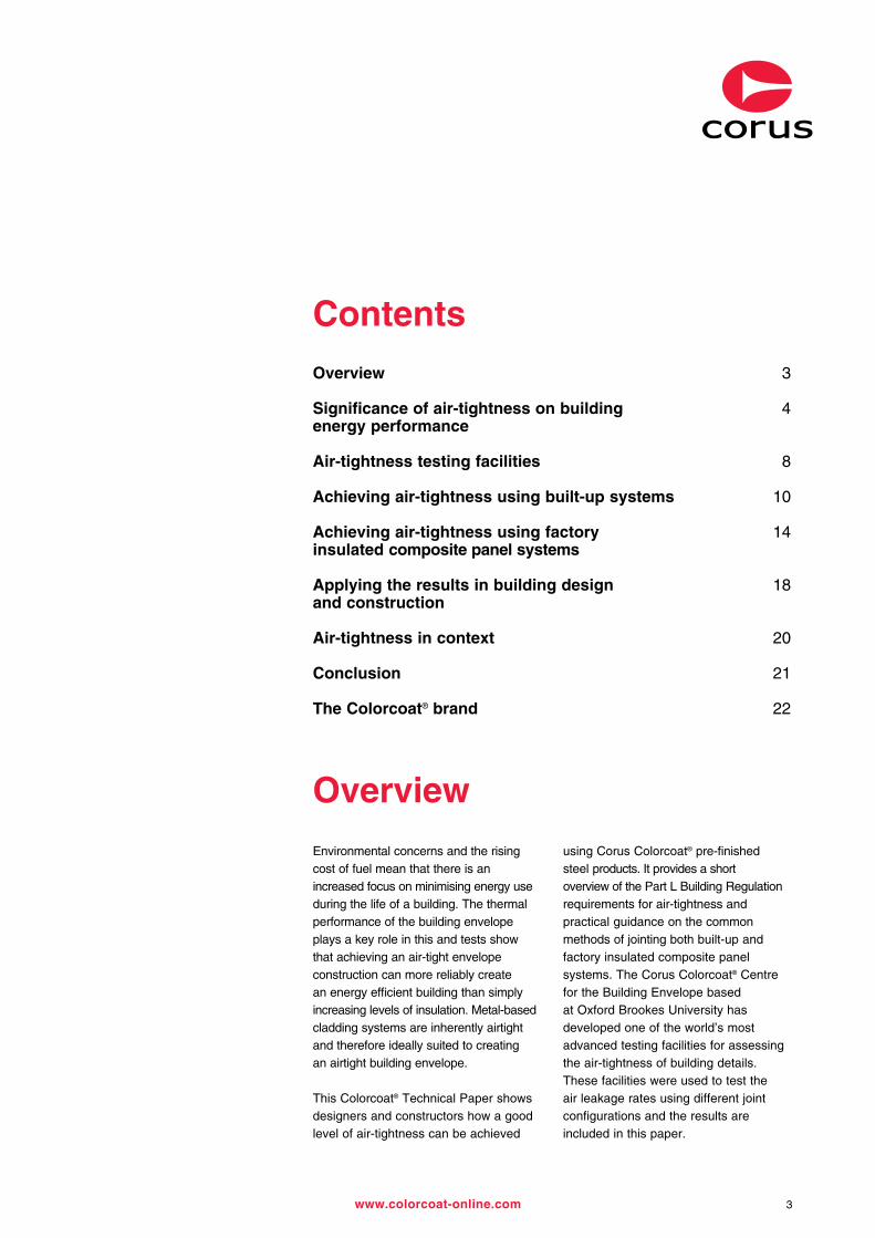
Overview 3
Significance of air-tightness on building 4 energy performance
Air-tightness testing facilities 8
Achieving air-tightness using built-up systems 10
Achieving air-tightness using factory 14 insulated composite panel systems
Applying the results in building design 18 and construction
Air-tightness in context 20
Conclusion 21
The Colorcoat® brand 22
Overview
Environmental concerns and the rising cost of fuel mean that there is an increased focus on minimising energy use during the life of a building. The thermal performance of the building envelope plays a key role in this and tests show that achieving an air-tight envelope construction can more reliably create an energy efficient building than simply increasing levels of insulation. Metal-based cladding systems are inherently airtight and therefore ideally suited to creating an airtight building envelope.
This Colorcoat® Technical Paper shows designers and constructors how a good level of air-tightness can be achieved
using Corus Colorcoat® pre-finished steel products. It provides a short overview of the Part L Building Regulation requirements for air-tightness and practical guidance on the common methods of jointing both built-up and factory insulated composite panel systems. The Corus Colorcoat® Centre for the Building Envelope based at Oxford Brookes University has developed one of the world’s most advanced testing facilities for assessing the air-tightness of building details. These facilities were used to test the air leakage rates using different joint configurations and the results are included in this paper.

Changes to Part L (implemented from April 2006) and rising energy prices have put a renewed emphasis on improving the energy performance of buildings. Studies have shown that the simple approach of increasing insulation thickness is unlikely to pay off in the long run. Other means of reducing energy usage are now required.
Energy is lost through the building envelope via 3 main routes:
• Building fabric losses, through the insulation.
• Linear thermal bridging, through building details and areas of reduced thermal resistance.
• Air-tightness, the entry of cold air through joints and interfaces, which requires heating to the building’s ambient temperature.
4 Colorcoat Connection® helpline +44 (0) 1244 892434
Significance of air-tightness on building energy performance
Control system
Low/zero carbon energy
Operation requirements
Process heat generation
Heating system
Lighting
Ventilation
Air conditioning
Solar gain
Natural day lighting
Linear thermal bridging
Building fabric performance (elemental U values + areas)
Air tightness (air infiltration)
Building envelope performance
Fig. 1. Factors which affect building CO2 emission rate.
Air changes/hour x building volume x specific heat capacity of air x density of air x temp raise 3600
The evaluation of air infiltration rates for large buildings has established the following relationship:
The energy (watts) required to heat the cold air entering the building is given by:
Air changes/hour = Air-tightness @ 50 Pa x envelope area* Cladding area x 60
* Envelope area is the cladding and floor slab area combined.

Air infiltration Wall fabric Roof fabricRoof light fabric Floor slab Linear bridging
5www.colorcoat-online.com
Note: values dependant on building geometry.
As illustrated, air-tightness offers the greatest opportunity for reducing heat loss through the building envelope. To maintain a good working environment within a building, a number of air changes per hour are necessary, dependent on activity levels. Best practice dictates that the building envelope should be as air-tight as possible, with controlled ventilation.
Fig. 2. Building envelope energy losses.

Significance of air-tightness on building energy performance
6 Colorcoat Connection® helpline +44 (0) 1244 892434
Building regulation requirements. Approved document L (2006)
Air-tightness is measured in m3 of air per hour per m2 of building envelope at an applied pressure of 50 Pa. The area of the building envelope includes the walls, roof and floor slab. In practice, the floor slab can be considered air-tight.
The concept of air-tightness was first introduced into Building Regulations in England and Wales in the 2002 revision of “approved document L”. In this document,
a maximum allowable air leakage rate of 10 m3/h/m2 was introduced for all buildings other than dwellings greater than 1000 m2.
The 2006 update to Part L has extended this further. All buildings must be pressure tested, unless the floor area is less than 500 m2, when a default value of 15 m3/h/m2 can be used. For buildings over 500 m2, a maximum reasonable design limit for air-tightness is 10 m3/h/m2.
The new requirements are less prescriptive than 2002, however it will be difficult to meet the overall building CO2 emission rate without a reasonably air-tight building envelope.
Air-tightness is tested using a number of large mobile fan units, to pressurise the building to 50 Pa. The volume of air leakage is divided by the cladding (including floor slab) area.
In a typical pre-finished steel-clad building, the air-tightness barrier is provided by the interior (or “liner”) side of the envelope. While the outer sheet of an insulated envelope will provide weather protection, and will be sealed in order to prevent water leaks, it is important that it is not relied upon for air-tightness. This is for two main reasons:
1. The insulation cavity on a build up system is slightly ventilated to allow air movement and so eliminate condensation build up in the cavity.
2. Sealing at the liner side will prevent water vapour from inside the building penetrating the insulation.
The first step in constructing an air-tight building is to identify the liner as the air-tightness barrier and ensure this is focused on during the design and construction of the building envelope.
The means of achieving air-tightness for a building using a built-up, insulated, pre-finished steel cladding system will be different from one clad with factory insulated composite panels. Both systems can provide extremely good air-tightness, using good detailing and construction.
Achieving air-tightness
Potential air leakage pathsPre-finished steel cladding is inherently air-tight. The management of the interfaces between the cladding sheets is critical to ensure a high performance building envelope. The following interfaces should be considered:
• Metal cladding side and end lap joints.• The interface between metal cladding
and pre-fabricated flashings at building corners, ridges, eaves and verges.
• The interface between metal cladding and the floor slab/dwarf wall and other building envelope materials.
• Unplanned penetrations in the cladding.
This paper assesses the requirements for metal cladding side and end lap joints and the interface between metal cladding and flashing, although some of these principles can also be applied to other interfaces and penetrations.

7www.colorcoat-online.com
Built-up systemAir-tightness for built-up systems is generated by the liner sheet. Sealant tapes or beads are used to seal the overlap joints between adjacent sheets. It is normal practice to have a slightly vented insulation cavity to reduce condensation risks. The external or weather sheet of the building envelope does not normally contribute to air-tightness.
Internal sealant bead Sealed liner sheet generates air tightness
Liner sheetExternal side lap tape
Thermal insulationTrapezoidal roof sheet
Factory insulated composite panelsAir-tightness is achieved by the compression of factory fitted seals on the liner side of the joint. Sealant fitted on the outer sheet is for weather tightness only. Care must be taken to ensure that condensation does not occur inside the joint.
The position of the factory filled seals will be specific to the individual panel. For further information on seal position and potential condensation contact the cladding system manufacturer.
Primary fastener Compressible seal factory applied
Sealed rivets or self drilling fasteners with sealing washers at no more than 450 mm centres
Robust interlocking joint. Giving a flush internal finish
Seal generates air-tightness
Fig. 3. Cross section schematic through a built-up system.
Fig. 4. Cross section schematic through a factory insulated composite panel

8 Colorcoat Connection® helpline +44 (0) 1244 892434
Corus has established the Colorcoat® Centre for the Building Envelope at Oxford Brookes University, to support research in the use of pre-finished steel in the building envelope. A key area of study is how the building envelope can contribute to the aims of sustainable development, with work focusing on minimising operational energy as well as life cycle analysis and the development of modern methods of construction.
This technology will be invaluable in helping architects and contractors comply with the changes to Part L (2006) Building Regulations. In developing these testing facilities with Oxford Brookes University Architectural School, Corus believes the results will be used to provide more air-tight building details, reducing energy bills for the client and providing more security from uncertain fuel prices.
At the Colorcoat® Centre different cladding joint assemblies have been fabricated on a test rig, which was
then pressurised to 50 Pa (the same pressure used to test whole buildings). The pressure inside the test rig is automatically controlled, allowing the air leakage rate for the cladding system and per linear metre of joint to be calculated. The results of this study show that good air-tightness is achieved by what would be recognised as “best practice” rather than costly new systems.
A number of cladding joints have been assessed in order to provide this guidance:
Built-up systems• Side lap joints.• End lap joints.• Side lap to flashing joints.• End lap to flashing joints.
Factory insulated composite panel systems• Side lap joints.• End lap joints.• Side lap to flashing joints.• End lap to flashing joints.
Air-tightness testing facilities

9www.colorcoat-online.com
Test panel Sealed box
Pressure tapping
Micro manometer
0-1 mA
Data logger
4-20 mA
Pressure transducer
Pressure tapping
Air
Flow measurement device
Fan
Inverter drive 240 V AC
Temperature probe
Fig. 5. Schematic of air-tightness test cell.

Side lap joints are formed where the profiled edge of one sheet overlaps the edge of the adjacent sheet. Liner sheets are normally 0.4 mm or 0.7 mm thick. The joint is sealed either using a sealant bead, which is placed inside the overlap joint, or an external tape, which is placed over the joint line on the cavity side of the liner sheet. The joint can be reinforced with stitcher screws or rivets. This is a requirement for most firewall constructions.
Side lap joints account for approximately 75% of joint length in the cladding. There is approximately 1 metre of joint for every square metre of cladding; depending on the sheet cover width. For this reason, effective sealing of this joint provides the basis of an air-tight cladding system.
Any edge damage to the sheet profile will affect the tightness of the overlap joint and the performance of unsealed joints will be poor and have a high
degree of variability. The use of a good quality sealant tape (such as Polyband or T-foil) or an internal sealant bead will produce a good quality air-tight joint.
When using an external tape, it is important to note that the stitcher screws will not provide any additional air-tightness, although they can add
to the longevity of the joint. When using an internal sealant bead, stitcher screws are necessary for compression of the bead, increasing the performance and longevity of the joint.
(Consult cladding system manufacturers for the recommended size and grade of sealant beads).
Achieving air-tightness using built-up systems
10 Colorcoat Connection® helpline +44 (0) 1244 892434
Built-up system side lap joints
Internal sealant bead Sealed liner sheet generates air tightness
Liner sheetExternal side lap tape
Thermal insulationTrapezoidal roof sheet
Joint details Leakage rate m3/h/m 0.4 mm liner 0.7 mm liner
Unsealed unstitched >10.00 >10.00
Unsealed stitched @ 450 mm >5.00 >5.00
External sealant tape <0.20 <0.20
External sealant tape and stitching @ 450 mm <0.20 <0.20
Internal sealant bead <0.25 <0.40
Internal sealant bead and stitching @ 450 mm <0.20 <0.20
Table 1: Side lap joint configurations and corresponding air leakage rates
Recommended specification
Key
Fig. 6. Cross section schematic through a built-up system.

11www.colorcoat-online.com
Tape
Liner sheet
Liner sheet
Sealant bead
End lap joints are formed where the profiled end of one sheet overlaps the end of the adjacent sheet. The minimum recommended overlap is 60 mm. Liner sheets are normally 0.4 mm or 0.7 mm thick. The joint is sealed using a sealant bead, which is placed inside the overlap joint, or using an external tape, which is placed over the joint line on the cavity side of the liner sheet. The joint is reinforced with stitcher screws or rivets.
Stitcher screws should be fitted in every valley to provide compression of the sealant bead. The use of a good quality sealant bead will produce a good quality air-tight joint. If the sheet is secured only in alternate valleys, the unsecured valleys can open slightly, stressing the sealant bead and compromising the performance and longevity of the joint.
An external sealant tape can provide an air-tight joint, but is difficult to secure accurately around the profiles, which
can lead to workmanship issues and reduced performance. Poorly laid tape can also trap internal condensation, resulting in potential corrosion of the liner sheet.
(Consult cladding system manufacturer for the recommended size and grade of sealant beads / tapes).
Built-up system end lap joints
Joint details Leakage rate m3/h/m 0.4 mm liner 0.7 mm liner
Unsealed, stitched alternate valleys <45.00 <45.00
Unsealed, stitched every valley <15.00 <15.00
Internal sealant bead, stitched alternate valleys <1.00 <0.50
Internal sealant bead stitched every valley <0.30 <0.30
External sealant tape, stitched alternate valleys <0.20 <0.20
External sealant tape, stitched every valley <0.20 <0.20
Table 2: End lap joint configurations and corresponding air leakage rates
Recommended specification
Key
Fig. 7. Schematic of a built-up system end lap joint.
Achieving air-tightness using built-up systems
12 Colorcoat Connection® helpline +44 (0) 1244 892434
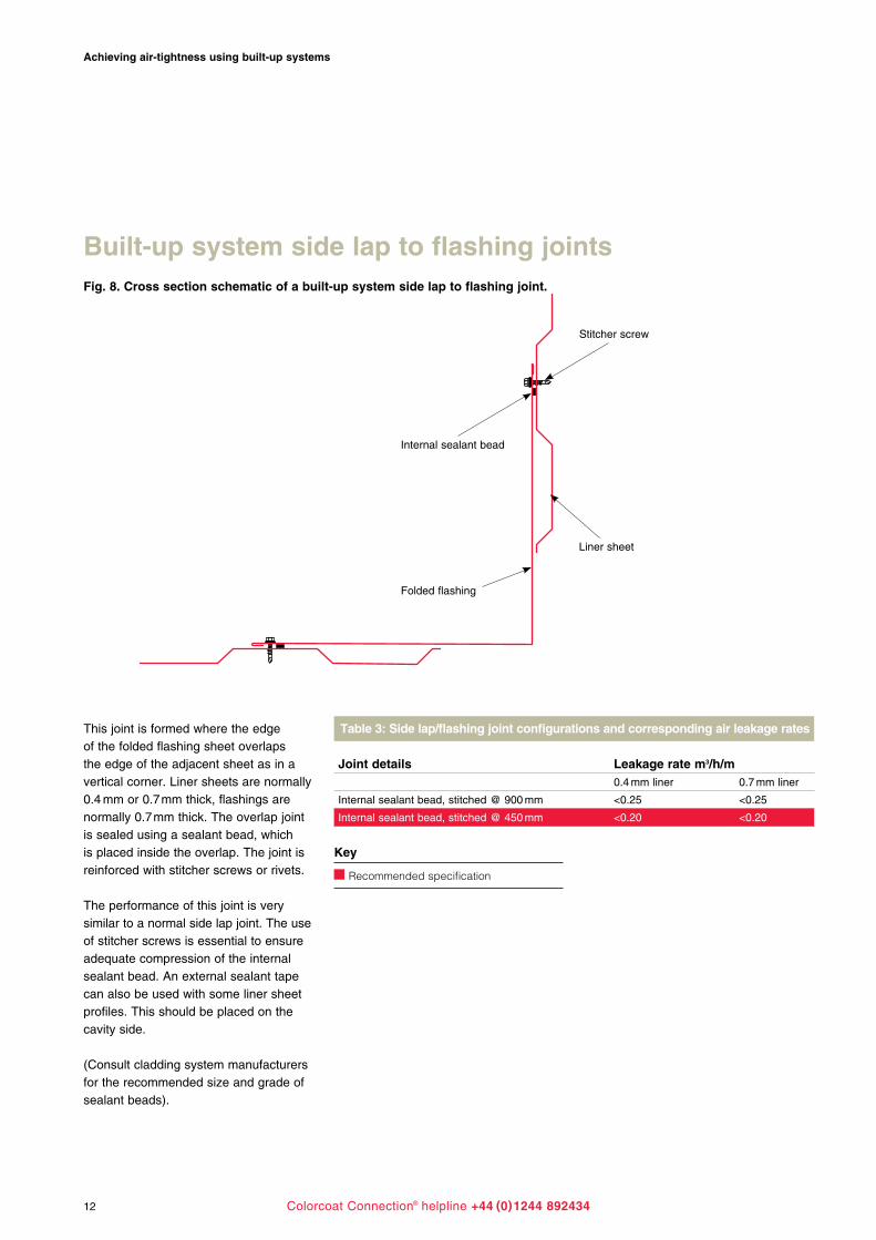
Built-up system side lap to flashing joints
Stitcher screw
Internal sealant bead
Liner sheet
Folded flashing
This joint is formed where the edge of the folded flashing sheet overlaps the edge of the adjacent sheet as in a vertical corner. Liner sheets are normally 0.4 mm or 0.7 mm thick, flashings are normally 0.7 mm thick. The overlap joint is sealed using a sealant bead, which is placed inside the overlap. The joint is reinforced with stitcher screws or rivets.
The performance of this joint is very similar to a normal side lap joint. The use of stitcher screws is essential to ensure adequate compression of the internal sealant bead. An external sealant tape can also be used with some liner sheet profiles. This should be placed on the cavity side.
(Consult cladding system manufacturers for the recommended size and grade of sealant beads).
Joint details Leakage rate m3/h/m 0.4 mm liner 0.7 mm liner
Internal sealant bead, stitched @ 900 mm <0.25 <0.25
Internal sealant bead, stitched @ 450 mm <0.20 <0.20
Table 3: Side lap/flashing joint configurations and corresponding air leakage rates
Recommended specification
Key
Fig. 8. Cross section schematic of a built-up system side lap to flashing joint.

13www.colorcoat-online.com
Built-up system end lap to flashing joints
Gun grade mastic
Compressible foam filler block
Stitcher screw
Flashing
Liner sheet
This joint is formed where the end of the profiled sheet overlaps the folded flashing sheet as in a ridge or eaves detail. The minimum recommended overlap is 75 mm. Liner sheets are normally 0.4 mm or 0.7 mm thick, whilst flashings are normally 0.7 mm thick. The joint is sealed using profiled filler blocks, which fit into the liner sheet profile and become compressed between the profile and the flashing. Filler blocks are generally made from Ethylene Propylene Diene Monomer (EPDM) or Polyethylene (PE) foam. Stitcher screws create compression and reinforcement of the joint.
It is essential that filler blocks are matched to the profile of the cladding sheet used. The use of a suitable gun-grade mastic to bond the filler blocks in position will generally increase performance and also assists with locating the blocks during assembly. To ensure good compression of the
filler blocks and longevity of the joint, the sheeting should be secured through every valley.
There is no discernable difference in performance between EPDM and PE filler blocks.
Joint details Leakage rate m3/h/m 0.4 mm liner 0.7 mm liner
EPDM filler block stitched alternate valleys >10.00 <5.00
PE filler block stitched alternate valleys >10.00 <5.00
Bonded EPDM filler block stitched alternate valleys <2.00 <2.00
Bonded PE filler block stitched alternate valleys <2.00 <2.00
EPDM filler block stitched every valleys <0.50 <0.50
PE filler block stitched every valleys <0.50 <0.50
Bonded EPDM filler block stitched every valleys <0.25 <0.25
Bonded PE filler block stitched every valley <0.25 <0.25
Table 4: End lap/flashing joint configurations and corresponding air leakage rates
Recommended specification
Key
Fig. 9. Schematic of a built-up system end lap to flashing joint.

14 Colorcoat Connection® helpline +44 (0) 1244 892434
Achieving air-tightness using factory insulated composite panel systemsFactory insulated composite panel system side lap joints
Compressible seal factory applied
Sealed rivets or self drilling fasteners with sealing washers at no more than 450 mm centres
Robust interlocking joint giving a flush internal finish
Additional external foam/mastic seal
Primary fastener
Lateral compression
Additional foam seal
The edge detail of a factory insulated composite panel is designed to interlock with its adjacent panel, forming an air-tight and weather-tight seal. A compressible foam seal is usually incorporated into the edge tape detail, which seals against the adjacent panel. The two panels must be held tightly together during installation to ensure adequate compression of the seal. Additional supplementary sealing may also be used.
Side lap joints typically account for approximately 75% of joint length in the cladding. There is approximately 1 metre of joint for every square metre
of cladding, depending on the panel cover width. For this reason, effective sealing of these joints provide the basis of an air-tight cladding system.
Performance of the basic joint is reliant on adequate compression of the internal tape seal. Any edge damage to the panel or panel misalignment, could mean that joints do not fully close, therefore compromising air-tightness. The use of an external sealant bead, or foam seal, in addition to the internal edge tape seal will greatly enhance performance and tolerance of the joint to inadequate lateral compression.
It should be noted that this in effect moves the air-tight barrier to the outer sheet and could potentially cause a build up of condensation in the joint detail.
The use of a supplementary foam seal (or mastic bead) in the interlocking joint on the liner side of the panel will greatly enhance performance and tolerance of the joint to inadequate lateral compression. Importantly, this also maintains the air seal on the liner side of the panel.
(Consult cladding system manufacturers for recommended size and grade of sealant / foam seals.)
Joint details Leakage rate m3/h/m Foam edge seal only Foam edge and Foam edge seal and Foam edge seal additional external sealant bead external foam seal internal foam seal
Fully compressed joint <0.50 <0.20 <0.20 <0.20
Joint compressed to 1.75 mm <5.00 <0.20 <0.20 <0.20
Joint compressed to 3.5 mm >10.00 <0.20 <0.20 <1.50*
Table 5: Side lap joint configurations and corresponding air leakage rates for varying lateral compression
* The performance of the joint is dependant on the size of the internal foam seal fitted. A larger diameter seal will be more tolerant of inadequate joint compression.
Fig. 10. Cross section schematic through a factory insulated composite panel system.

15www.colorcoat-online.com
Factory insulated composite panel system end lap joints
Sealant beads or foam pad
Sealant bead
Outer sheet
Liner sheet
This joint is formed where the profiled end of an external sheet overlaps the end of the adjacent sheet. The joint must be sited over a purlin/sheeting rail. The liner and insulation foam on the overlapping panel must be cut back to facilitate this, a process which is usually done during panel manufacture. The minimum recommended overlap is 100 mm. The joint is sealed using a sealant bead, which is placed inside the overlap joint. A compressible foam
tape or mastic bead, should also be applied to the purlin. The joint is reinforced with stitcher screws or rivets, which also compress the sealant beads.
The use of sealant beads in the external sheet overlap joint will, when adequately secured, result in an air-tight joint. Alternate through fixings will provide adequate compression of the sealant beads. It should be noted, however, that this is effectively moving the
air-tight barrier to the outer sheet, which could potentially cause a build up of condensation in the joint detail. The use of supplementary foam seals (or mastic beads) on the purlin will provide an effective seal on the liner side of the panel and will greatly enhance performance.
(Consult cladding system manufacturers for recommended size and grade of sealant / foam seals.)
Joint details Leakage rate m3/h/m No sealant, alternate valley through fix only >2.50
No sealant, alternate valley through fix. Alternate valley stitched >2.50
2 sealant beads, alternate valley through fix only <0.30
2 sealant beads, alternate valley through fix. Alternate valley stitched <0.30
2 sealant beads, alternate valley through fix Foam pad/sealant beads on purlin <0.20
Table 6: End lap joint configurations and corresponding air leakage rates
Recommended specification
Key
Fig. 11. Cross section schematic of a factory insulated composite panel system end lap joint.

Achieving air-tightness using factory insulated composite panel systems
16 Colorcoat Connection® helpline +44 (0) 1244 892434
Factory insulated composite panel system side lap to flashing joints
Composite cladding panel
Sealant
Flashing
This joint is formed where the panel edge overlaps the edge of the folded flashing sheet as in a vertical corner. Flashings are normally 0.7 mm thick. The overlap joint is sealed using a sealant bead, which is placed inside the overlap joint. The joint is reinforced with stitcher screws or rivets, which also compress the sealant bead.
The performance of this joint is very similar to a built-up system, flashing joint. The use of stitcher screws is essential to ensure adequate compression of the internal sealant bead.
(Consult cladding system manufacturers for recommended size and grade of sealant / foam seals.)
Joint details Leakage rate m3/h/m Internal sealant bead, stitched @ 1900 mm <1.50
Internal sealant bead, stitched @ 900 mm <0.25
Internal sealant bead, stitched @ 450 mm <0.20
Table 7: Side lap / flashing joint configurations and corresponding air leakage rates
Recommended specification
Key
Fig. 12. Cross section schematic of a factory insulated composite panel system side lap to flashing joint.

17www.colorcoat-online.com
Factory insulated composite panel system end lap to flashing joints
Composite cladding panel
Sealant
Flashing
This joint is formed where the end of the panel overlaps the edge of the folded flashing sheet as in a ridge or eaves detail. Flashings are normally 0.7 mm thick. The overlap joint is sealed using a sealant bead which is placed inside the overlap joint. The minimum recommended overlap is 75 mm.
It should be noted that profiled filler blocks are not normally used,
due to the very shallow micro rib /plank profile of the internal liner sheet. Compression of the sealant and reinforcement of the joint is created by stitcher screws / primary fasteners.
Due to the rigidity of the panel, there is minimal difference in performance when additional fasteners are used. Through fixings should be specified
for every valley for structural (wind load) requirements.
The sealant bead must be of an adequate size to accommodate the small profile in the liner sheet of the composite panel.
(Consult cladding system manufacturers for recommended size and grade of sealant / foam seals.)
Joint details Leakage rate m3/h/m No sealant. Alternate through fix >20.00
Internal sealant bead. Alternate through fix <0.20
Internal sealant bead through fix every valley <0.20
Table 8: End lap/flashing joint configurations and corresponding air leakage rates
Recommended specification
Key
Fig. 13. Schematic of a factory insulated composite panel system end lap to flashing joint.

18 Colorcoat Connection® helpline +44 (0) 1244 892434
Applying the results in building design and constructionThe tables below summarise recommended practices and measured joint leakage rates. The building envelope is configured using combinations of the joints included here, for example, a gable joint incorporates flashing to side lap and flashing to end lap joints.
A pre-finished steel building envelope can easily surpass the requirements of the revised Part L (2006) provided that the metal cladding joints are correctly installed in accordance with the system manufacturers guidance and that an approved sealant tape or internal sealant bead is used. Consult with cladding system manufacturers for the recommended size and grade of sealant bead
It is important to recognise that construction site conditions are not always ideal. The Corus Colorcoat®
Centre for the Building Envelope carried out tests to assess whether real world issues, such as damp or dirty pre-finished steel surfaces, will affect the bond of the sealant tape to the liner sheet. These indicate that provided the material is only moderately wet / dirty, (typical of early morning dew and airborne construction dust) and that adequate pressure is applied when fitting the sealant tape, a good quality seal can still be achieved. Care must be taken to ensure that damage does not occur to sheet edges and that debris is not present in overlap joints.
Joint details Recommendation Leakage rate m3/h/m Side lap joint External sealant tape <0.20
Internal sealant bead, stitched @ 450 mm <0.20
Side lap flashing joint Internal sealant bead, stitched @ 450 mm <0.20
External sealant tape <0.20
End lap joint Internal sealant bead, stitched every valley <0.30
End lap flashing joint Bonded EPDM or PE filler block, stitched every valley <0.25
Table 9: Built-up system – recommended joint sealing practice
Joint details Recommendation Leakage rate m3/h/m Side lap joint Fully compressed edge seal <0.50
Additional internal foam seal on liner sheet interlock <0.20
Side lap flashing joint Internal sealant bead, stitched @ 450 mm <0.20
End lap joint 2 sealant beads, alternate valley through fix. Foam pad/sealant beads on purlin <0.10
End lap flashing joint Internal sealant bead, through fix every valley <0.20
Table 10: Factory insulated composite panels – recommended joint sealing practice

19www.colorcoat-online.com
Provided pre-finished steel cladding is correctly installed, the main sources of air infiltration will be other elements of the building envelope, such as: interfaces with other cladding materials, for example masonry dwarf walls or the floor slab, unplanned penetrations through the building envelope and gaps around vehicle access doors. Further work is currently underway at the Corus Colorcoat® Centre for the building envelope and better understanding of
these complex joints. Use of the principles detailed in the Colorcoat® Technical Paper will minimise air leakage around such elements but it is important at the design stage to consider minimising difficult functions or leaky materials such as blockwork or masonry.
Attention to detail and a high standard of site workmanship are required to ensure that unplanned leakage paths are minimised.
Testing has been carried out to establish the leakage rate through unplanned holes in the metal cladding.
Building practice has focused on sealing the outer sheet of a built-up system to ensure a weather tight envelope. Similar attention to detail should also be paid to the seal on the liner side of the envelope to ensure continuity of the air-tight layer.
Joint details Leakage rate m3/h/m Standard joint Damp Dirty Reduced pressure*
Unsealed unstitched >10.00 >10.00 >10.00 NA
Unsealed stitched @ 450 mm >5.00 >5.00 >5.00 NA
External sealant tape <0.20 <0.20 <0.50 <0.50
Table 11: Built-up systems. Side lap joint leakage rates under simulated site conditions
* Reduced pressure was simulated by applying the tape using a hand brush.
Fig. 14. Air-leakage rate for holes.

20 Colorcoat Connection® helpline +44 (0) 1244 892434
Air-tightness in contextThis illustrates how a building would achieve an air-tightness rating which complies with Part L Regulations. For the dimensions specified below this building would be allowed a maximum air permeability at 50 Pa of 10 x 3729 = 37290 m3/h to pass Part L.
If all the relevant joints had a linear leakage of 0.5 m3/h/m, the total leakage from the pre-finished steel envelope attributable to joints would be 0.43 m3/h/m2 or 4.3% of the maximum allowable leakage.
It can be seen from this example that correct sealing of the metal to metal end and side lap joints, which form the majority of the potential air leakage paths, forms the basics of a good air tightness performance.
Joint details Leakage from joints – linear leakage of (m3/h/m) Joints Length (m) 0.10 0.25 0.50 1.00 2.00 3.00
Corner 32.0 3.20 8.00 16.00 32.00 64.00 96.00
Wall side lap 1266.9 126.69 316.73 633.46 1266.92 2533.84 3800.76
Wall end lap 160.0 16.00 40.00 80.00 160.00 320.00 480.00
Roof side lap 1186.5 118.65 296.62 593.25 1186.50 2373.00 3559.50
Roof end lap 240.0 24.00 60.00 120.00 240.00 480.00 720.00
Verge 40.2 4.02 10.06 20.11 40.22 80.44 120.66
Eaves 120.0 12.00 30.00 60.00 120.00 240.00 360.00
Perimeter 160.0 16.00 40.00 80.00 160.00 320.00 480.00
Ridge 60.0 6.00 15.00 30.00 60.00 120.00 180.00
Valley 0.0 0.00 0.00 0.00 0.00 0.00 0.00
Total leakage 327 816 1633 3266 6531 9797
Building dimensions Height (m) 8 Number of ridges 1
Width (m) 20 Roof pitch height (m) 1.1
Length (m) 60 Roof slope length (m) 10.1
Wall panel width (m) 1 Floor area (m2) 1200.0
Wall panel height (m) 4 Roof area (m2) 1206.6
Roof panel width (m) 1 Wall area (m2) 1322.0
Roof panel height (m) 3.3 Envelope area including floor (m2) 3728.7
Roof pitch (degrees) 6 Total enclosed volume (m3) 9610.5
Table 12: Details of joint lengths and associated average joint leakage rates

21www.colorcoat-online.com
ConclusionsIn summary, it is worth remembering that steel is an inherently air-tight material, so the only air-leakage paths in a steel building envelope are where there are gaps left at junctions. Adopting the approaches detailed in this paper should minimise gaps at the majority of junctions. It should be noted, however, that a target air-leakage rate of 10, 5 or even 3 m3/m2/h allows, on average, a gap of 700 mm2, 380 mm2 or 200 mm2 for every 1 m2. Given that the target air-tightness is for the whole building (including all openings, interfaces, floors, roof and walls) it is essential that the techniques described here
are adopted for the areas which are relatively easy to control, since gaps will inevitably appear elsewhere in the construction.
Experience has shown that with close attention to detail, steel-clad buildings should have no difficulty in achieving air-leakage rates of no more than 5 m3/m2/h, and often even less than 3 m3/m2/h. However, air-leakage is highly dependent on building geometry. Simple, large buildings have proportionately less potentially-leaky interfaces than more complex, small ones.
This paper has been assessed and approved as conforming to RIBA CPD guidelines. As such the content has been designated to fit under the following core curriculum headings:
General Headings1 Professional context2 Construction SkillsSubjects1 Sustainable architecture2 Specification writing and choosing materialsKnowledge levelGeneral awareness
To receive a CPD certificate for this paper, please go to www.colorcoat-online.com/cpd where you will be asked to correctly answer five short questions on the content of the paper before being issued with an electronic certificate.
CPD accreditation
22 Colorcoat Connection® helpline +44 (0) 1244 892434
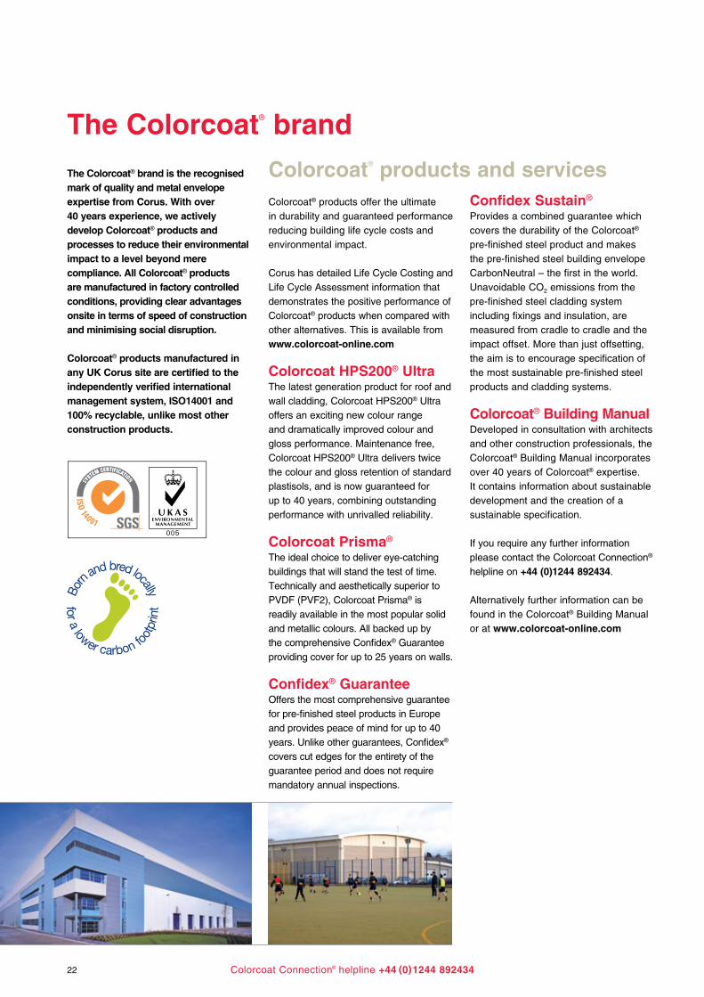
The Colorcoat® brand
The Colorcoat® brand is the recognised mark of quality and metal envelope expertise from Corus. With over40 years experience, we activelydevelop Colorcoat® products andprocesses to reduce their environmental impact to a level beyond mere compliance. All Colorcoat® products are manufactured in factory controlled conditions, providing clear advantages onsite in terms of speed of construction and minimising social disruption.
Colorcoat® products manufactured inany UK Corus site are certified to theindependently verified internationalmanagement system, ISO14001 and100% recyclable, unlike most otherconstruction products.
Colorcoat® products offer the ultimatein durability and guaranteed performancereducing building life cycle costs andenvironmental impact.
Corus has detailed Life Cycle Costing and Life Cycle Assessment information that demonstrates the positive performance of Colorcoat® products when compared with other alternatives. This is available from www.colorcoat-online.com
Colorcoat HPS200® UltraThe latest generation product for roof and wall cladding, Colorcoat HPS200® Ultra offers an exciting new colour rangeand dramatically improved colour andgloss performance. Maintenance free,Colorcoat HPS200® Ultra delivers twicethe colour and gloss retention of standard plastisols, and is now guaranteed for up to 40 years, combining outstanding performance with unrivalled reliability.
Colorcoat Prisma®
The ideal choice to deliver eye-catchingbuildings that will stand the test of time.Technically and aesthetically superior toPVDF (PVF2), Colorcoat Prisma® is readily available in the most popular solid and metallic colours. All backed up by the comprehensive Confidex® Guarantee providing cover for up to 25 years on walls.
Confidex® GuaranteeOffers the most comprehensive guarantee for pre-finished steel products in Europe and provides peace of mind for up to 40 years. Unlike other guarantees, Confidex® covers cut edges for the entirety of the guarantee period and does not require mandatory annual inspections.
Confidex Sustain®
Provides a combined guarantee whichcovers the durability of the Colorcoat®
pre-finished steel product and makesthe pre-finished steel building envelopeCarbonNeutral – the first in the world.Unavoidable CO2 emissions from thepre-finished steel cladding systemincluding fixings and insulation, aremeasured from cradle to cradle and theimpact offset. More than just offsetting,the aim is to encourage specification ofthe most sustainable pre-finished steelproducts and cladding systems.
Colorcoat® Building ManualDeveloped in consultation with architectsand other construction professionals, theColorcoat® Building Manual incorporatesover 40 years of Colorcoat® expertise.It contains information about sustainabledevelopment and the creation of asustainable specification.
If you require any further informationplease contact the Colorcoat Connection® helpline on +44 (0)1244 892434.
Alternatively further information can befound in the Colorcoat® Building Manualor at www.colorcoat-online.com
Colorcoat® products and services

There’s only one true
Ensure that it’s by Corus

www.colorcoat-online.com
Trademarks of CorusColorcoat, Colorcoat Connection, Confidex, Confidex Sustain, HPS200, Prisma and Repertoire are trademarks of Corus.
Care has been taken to ensure that the contents of this publication are accurate, but Corus Group plc and its subsidiary companies do not accept responsibility for errors or for information that is found to be misleading. Suggestions for, or descriptions of, the end use or application of products or methods of working are for information only and Corus Group plc and its subsidiaries accept no liability in respect thereof.
Before using products or services supplied or manufactured by Corus Group plc and its subsidiaries, customers should satisfy themselves as to their suitability.
Copyright 2007 Corus
Language English 0807
Sales contact detailsCorus Colors Shotton Works Deeside Flintshire CH5 2NH United KingdomT: +44 (0)1244 812345F: +44 (0)1244 831132www.colorcoat-online.com
Colorcoat Connection® helplineT: +44 (0)1244 892434F: +44 (0)1244 836134 e-mail: [email protected]