Colorado Department of Transportation Roadway Design Guide
129
Colorado Department of Transportation Roadway Design Guide Chapter 14 Bicycle and Pedestrian Facilities Adopted November 1, 2011 Rev. 1 – January 2013 Rev. 2 – October 2015
Transcript of Colorado Department of Transportation Roadway Design Guide

Colorado Department of Transportation Roadway Design Guide
Chapter 14 Bicycle and Pedestrian Facilities Adopted November 1, 2011 Rev. 1 – January 2013 Rev. 2 – October 2015


Table of Contents October 2015
TOC-1
TABLE OF CONTENTS
CHAPTER 14
BICYCLE AND PEDESTRIAN FACILITIES
14.0 INTRODUCTION ......................................................................................... 7 14.0.1 Intent of Chapter 14 - Design of Bicycle and Pedestrian Facilities ......................7
14.0.2 CDOT Bike and Pedestrian Policy Directive 1602.0 ............................................7
14.0.3 CDOT Bike and Pedestrian Procedural Directive 1602.1 ....................................8
14.0.4 Design Exceptions ................................................................................................9
14.0.5 Federal Guidance Concerning Bicycle and Pedestrian Facilities .........................9
14.0.5.1 US DOT Policy Statement .............................................................9 14.0.5.2 Restrictions on Severing Bicycle and Pedestrian Facilities ...........9
14.0.6 Context Sensitive Design ....................................................................................10
14.0.7 User Counts .........................................................................................................10
14.1 BICYCLE FACILITIES ............................................................................. 10 14.1.1 Accommodating Bicycles ...................................................................................10
14.1.1.1 Sharing Roadway Space ...............................................................11 14.1.1.2 Role of Design Factors .................................................................11 14.1.1.3 The Bicycle as a Design Vehicle ..................................................12
14.1.2 Bike Routes .........................................................................................................14
14.1.2.1 General Bike Routes .....................................................................15 14.1.2.2 Numerically Labeled Bike Routes ...............................................15
14.1.3 Shared lanes ........................................................................................................16
14.1.3.1 Bicycle May Use Full Lane Sign (R4-11) ....................................16 14.1.3.2 SHARE THE ROAD Sign Assembly (W11‐1 + W16‐1P) ................17 14.1.3.3 Shared Lane Markings ..................................................................19
14.1.4 Wide Curb Lanes ................................................................................................19
14.1.5 Paved Shoulders ..................................................................................................20
14.1.5.1 Additional Width ..........................................................................20 14.1.5.2 Shoulders on Steep Grades ...........................................................22 14.1.5.3 Rumble Strips ...............................................................................22 14.1.5.4 Shoulders at Intersections .............................................................22
14.1.6 Bike Lanes ..........................................................................................................23
14.1.6.1 Bike Lane Width ..........................................................................23 14.1.6.2 Designating Bike Lanes ................................................................24 14.1.6.3 Contraflow Bike Lanes .................................................................24 14.1.6.4 Bike Lanes at Driveways and Intersections .................................26 14.1.6.5 Buffered Bike Lanes .....................................................................39 14.1.7.1 Signal Detection Loops in Bike Lanes .........................................43 14.1.7.2 Signal Timing for Bicycles ...........................................................43
October 2015 Table of Contents
TOC-2
14.1.8 Bike Lanes at Roundabouts ................................................................................45
14.1.9 Separated Bike Lanes (Cycle track) ....................................................................46
14.1.10 Bicycle Boulevards .............................................................................................46
14.1.11 Alternative Routes ..............................................................................................46
14.1.12 Other Roadway Considerations ..........................................................................47
14.1.12.1 Cross Slopes .................................................................................47 14.1.12.2 Drainage Inlets and Utility Covers ...............................................47 14.1.12.3 Railroad Crossings .......................................................................48 14.1.12.4 Bridges and Tunnels .....................................................................49
14.2 SHARED USE PATHS ............................................................................... 49 14.2.1 Surface Treatments .............................................................................................49
14.2.1.1 Paved Shared Use Path .................................................................49 14.2.1.2 Unpaved Shared Use Paths ...........................................................50
14.2.2 Design Speed ......................................................................................................50
14.2.3 Sight Distance .....................................................................................................50
14.2.3.1 Stopping Sight Distance ...............................................................51 14.2.3.2 Sight Distance on Horizontal Curves ...........................................52 14.2.3.3 Sight Distance on Vertical Curves ...............................................54 14.2.3.4 Sight Distance at Intersections .....................................................57
14.2.4 Shared Use Path Width .......................................................................................57
14.2.5 Cross Slope .........................................................................................................60
14.2.6 Clearances ...........................................................................................................60
14.2.7 Horizontal Alignment of Shared Use Paths ........................................................62
14.2.8 Vertical Alignment of Shared Use Paths ............................................................63
14.2.9 Intersections with Shared Use Paths ...................................................................64
14.2.9.1 Required Sight Triangles at Shared Use Path Intersections .........65 14.2.9.2 Traffic Control at Intersections with Shared Use Paths ...............70 14.2.9.3 Reducing Speeds on the Approach to Intersections .....................72 14.2.9.4 Curb Ramps ..................................................................................74 14.2.9.5 Prevention of Motor Vehicle Encroachment onto Shared
Use Paths ......................................................................................74 14.2.10 Underpass and Overpass Structures ....................................................................77
14.2.10.1 Width and Clearance for Structures Serving Shared Use Paths .............................................................................................77
14.2.10.2 Grades on Structures Serving Shared Use Paths ..........................78 14.2.10.3 Railings on Structures Serving Shared Use Paths ........................78 14.2.10.4 Railroad crossings ........................................................................78 14.2.10.5 Utilities .........................................................................................80 14.2.10.6 Traffic Calming on Shared Use Paths ..........................................80
14.2.11 Wayfinding on Shared Use Paths .......................................................................81

Table of Contents October 2015
TOC-3
14.2.12 Shared Use Paths Adjacent to the Roadway (Sidepaths) ....................................81
14.2.13 Safety Considerations of Sidepaths ....................................................................82
14.2.13.1 Potential Mitigation Measures to the Operational Challenges of Sidepaths ...............................................................83
14.2.14 Sidepath Clearance to the Adjacent Roadway ....................................................85
14.2.15 Equestrian Facilities ............................................................................................85
14.2.16 Other Considerations on Bicycle Facilities .........................................................86
14.2.16.1 Shared Use Path Lighting .............................................................86 14.2.16.2 Maintenance of Traffic .................................................................86 14.2.16.3 Integration of Bicycles with Transit .............................................87 14.2.16.4 Innovative Signing and Markings ................................................88 14.2.16.5 Maintenance of Bicycle Facilities ................................................91
14.3 PEDESTRIAN FACILITIES ..................................................................... 91 14.3.1 General Pedestrian Considerations .....................................................................91
14.3.1.1 Accommodating Pedestrians in the Right-of-Way .......................92 14.3.1.2 Operating Characteristics of Pedestrians ......................................93 14.3.1.3 Americans with Disabilities Act Requirements ...........................93 14.3.1.4 Curb Ramps and Blended Transitions ..........................................94 14.3.1.5 Vertical Changes in Grade ...........................................................94
14.3.2 Sidewalks ............................................................................................................95
14.3.2.1 Separation from Roadway ............................................................95 14.3.2.2 Sidewalk Width ............................................................................96 14.3.2.3 Protruding Objects ........................................................................96
14.3.3 Grade and Cross Slopes ......................................................................................97
14.3.4 Driveways ...........................................................................................................97
14.3.5 Sidewalk Lighting ...............................................................................................98
14.3.6 Transit Stops .......................................................................................................98
14.3.7 Pedestrian Crossings of Roadways .....................................................................98
14.3.8 Pedestrian Crossings at Intersections ..................................................................98
14.3.8.1 Pedestrian Crossings at Uncontrolled Approaches to Intersections .................................................................................98
14.3.8.2 Pedestrian Crossings at Stop and Yield Control Intersections .................................................................................99
14.3.8.3 Pedestrian Crossings at Signal Control Intersections ...................99 14.3.8.4 Pedestrian Crossings at Roundabouts .........................................100
14.3.9 Pedestrian Crossings at Midblock Locations ....................................................101
14.3.9.1 Rapid Rectangular Flashing Beacons .........................................102 14.3.9.2 Pedestrian Hybrid Beacons ........................................................104 14.3.9.3 Guidance for Traffic Control Selection at Midblock
Crossings ....................................................................................105 14.3.9.4 Additional Treatments at Midblock Crossings ...........................108

October 2015 Table of Contents
TOC-4
14.3.9.5 Signalized Pedestrian Crossings .................................................109 14.3.9.6 Grade Separated Pedestrian Crossings .......................................109 14.3.9.7 Sidewalk Crossings of Rail Lines ..............................................110
14.3.10 Other Pedestrian Considerations .......................................................................112
14.3.10.1 Traffic Calming ..........................................................................112 14.3.10.2 Pedestrian Amenities ..................................................................113 14.3.10.3 Pedestrian Wayfinding Signing ..................................................113 14.3.10.4 On-street Parking ........................................................................114
14.3.11 School Areas .....................................................................................................114
14.3.12 Maintenance of Traffic (58) ..............................................................................115
14.3.12.1 Pedestrian Considerations in Temporary Traffic Control Zones ..........................................................................................115
14.3.12.2 Accessibility Considerations ......................................................118 REFERENCES 119
INDEX 123
List of Figures
Figure 14-1 Bicycle Operating Space Requirements .....................................................................14 Figure 14-2 Examples of BICYCLE GUIDE Signs ..........................................................................15 Figure 14-3 Examples of BIKE ROUTE Signs ................................................................................15 Figure 14-4 U.S. BIKE ROUTE Sign ..............................................................................................16 Figure 14-5 Bicycles May Use Full Lane Sign ..............................................................................17 Figure 14-6 SHARE THE ROAD Sign Assembly ............................................................................18 Figure 14-7 SHARED LANE MARKING ..........................................................................................19 Figure 14-8 Advance Warning Stripe for Rumble Strips ..............................................................22 Figure 14-9 Bike slot at intersection. .............................................................................................23 Figure 14-10 Detail of Bike Lane Designation ..............................................................................24 Figure 14-11 Example Contraflow Bicycle Lane Markings ..........................................................26 Figure 14-12 Typical Bike Lane-Major Intersection, No Right Turn Lane- Curb and
Gutter .....................................................................................................................28 Figure 14-13 Typical Bike Lane-Major Intersection. Right Turn Lane ........................................29 Figure 14-14 Typical Bike Lane - Major Intersection, No Right Turn Lane, On-Street
Parking ...................................................................................................................30 Figure 14-15 Typical Bike Lane-Major Intersection. Right Turn Trap Lane-Bus Stop ................31 Figure 14-16 Typical Bike Lane-Tee Intersection. Right Turn Must Turn Right-Bus
Stop ........................................................................................................................32 Figure 14-17 Typical Bike Lane-Tee Intersection. Right Turn Lane-Bus Bay .............................33 Figure 14-18 Typical Bike Lane- Compact Interchange ...............................................................34 Figure 14-19 Typical Bike Lane-Rural Interchange ......................................................................35 Figure 14-20 Typical Bike Lane-Continuous Flow Intersection ...................................................36 Figure 14-21 Common Maneuvers for Bicyclists Turning Left at an Intersection ........................37 Figure 14-22 Two-Stage Left Turn Box ........................................................................................38 Figure 14-23 Example of Two-Stage Turn Queue Box at an Intersections. ..................................39

Table of Contents October 2015
TOC-5
Figure 14-24 Buffered Bike Lane ..................................................................................................40 Figure 14-25 Detail of Typical Buffered Bike Lane Designation .................................................41 Figure 14-26 Sample Buffered Bike Lane Transition at Intersection with Right Turn
Lane........................................................................................................................42 Figure 14-27 Bike Detection Symbol and Bicycle Signal Actuation Sign ....................................43 Figure 14-28 Multi-lane Roundabout ............................................................................................45 Figure 14-29 Bicycle Compatible Drainage Grates .......................................................................48 Figure 14-30 Bicycle Obstruction Marking in Advance of a Drop Inlet .......................................48 Figure 14-31 Potential Treatments at a Skewed Railroad Crossing ..............................................49 Figure 14-32 Stopping Sight Distance on a Shared Use Path Horizontal Curve ...........................53 Figure 14-33 Sight Distance on Crest Vertical Curves ..................................................................55 Figure 14-34 Path User Position Signs ..........................................................................................58 Figure 14-35 Mode Specific Guide Signs ......................................................................................59 Figure 14-36 SELECTIVE EXCLUSION Signs .................................................................................59 Figure 14-37 Conditions where Barriers to Embankments are Recommended .............................61 Figure 14-38 Bicycle HILL WARNING Sign ..................................................................................63 Figure 14-39 Functional Area of an Intersection ...........................................................................65 Figure 14-40 Illustration of Intersection Sight Triangle Dimensions ............................................67 Figure 14-41 Illustration of Intersection Sight Triangle Dimensions. Case C3, Yield
Condition................................................................................................................69 Figure 14-42 Illustration of Intersection Sight Triangle Dimensions. Path
Approaching Sidewalk ...........................................................................................70 Figure 14-43 INTERSECTION WARNING (W2 Series) and ADVANCE WARNING SIGNS
(W3 Series) Signs ..................................................................................................71 Figure 14-44 TRAIL CROSSING Assembly ....................................................................................72 Figure 14-45 Geometric Design to Slow Bicyclists on Intersection Approaches .........................73 Figure 14-46 Chicane on Approach to Intersection .......................................................................73 Figure 14-47 NO MOTOR VEHICLES Sign (R5-3) .........................................................................74 Figure 14-48 Example of Schematic Path Entry............................................................................75 Figure 14-49 Obstruction Striping around Bollards on Shared Use Paths ....................................76 Figure 14-50 Maximum Spacing of Resting Intervals on Shared Use Path Structure
Ramps ....................................................................................................................78 Figure 14-51 Example Signage and Markings at a Shared Use Path Crossing of a Rail
Road (49) ...............................................................................................................80 Figure 14-52 Example ADJACENT PATH Sign ..............................................................................84 Figure 14-53 Bicycle Facility DETOUR Signs ...............................................................................86 Figure 14-54 Bicycle Channel (41) ................................................................................................87 Figure 14-55 Shared Bus Buffered Bike Lane ...............................................................................88 Figure 14-56 Example Striping and Marking for a Bike Box .......................................................90 Figure 14-57 Protruding Objects ...................................................................................................97 Figure 14-58 Location of Pedestrian Crossings at Roundabouts (52) .........................................100 Figure 14-59 Detectable Warning Placement in Median Refuge Islands ....................................101 Figure 14-60 Angle Cut through a Median ..................................................................................102 Figure 14-61 Rapid Rectangular Flashing Beacon ......................................................................104 Figure 14-62 Pedestrian Hybrid Beacon Sequence (53) ..............................................................105 Figure 14-63 Approach Slope Markings for Raised Pedestrian Crossings (55) ..........................110

October 2015 Table of Contents
TOC-6
Figure 14-64 Example of Flashing-Light Signal Assembly for Pedestrian Crossings (56) .......................................................................................................................112
Figure 14-65 SCHOOL SPEED LIMIT Assembly ..........................................................................115 Figure 14-66 Pedestrian Facility DETOUR Sign ..........................................................................118
List of Tables
Table 14-1 Key Dimensions of Bicycles .......................................................................................13 Table 14-2 Key Performance Criteria ............................................................................................13 Table 14-3 Maximum motor vehicle service volumes for given Bicycle LOS grades ..................21 Table 14-4 Stopping Sight Distance for Bicycles ..........................................................................52 Table 14-5 Minimum Horizontal Clearance for Horizontal Sightline Offset for
Horizontal Curves ..................................................................................................54 Table 14-6 Minimum Length of Crest Vertical Curve Based on Stopping Sight
Distance..................................................................................................................56 Table 14-7 Minimum Radii and Superelevation for Bicycle Only Paths ......................................62 Table 14-8 Intersection Sight Distance ..........................................................................................67 Table 14-9 Required Sight Distance for Minor Leg of Yield Control ...........................................69 Table 14-10 Referral Table for Midbloack Crossing Treatments ................................................105 Table 14-11 Traffic Control Devices Tiers ..................................................................................106 Table 14-12 Roadway Volume less than 650 Vehicles per hour, vph (6,700 vehicles
per day1, vpd) .......................................................................................................107 Table 14-13 Roadway Volume greater than 650 vph1 (6,700 vpd), and less than 1,150
vph (12,000 vpd) ..................................................................................................107 Table 14-14 Roadway Volume greater than 1,1501 vph (12,000 vpd) ........................................107
October 2015 Bicycle and Pedestrian Facilities
14-7
CHAPTER 14
BICYCLE AND PEDESTRIAN FACILITIES
14.0 INTRODUCTION
Multimodal transportation is a key element of CDOT’s mission in providing improvements to the statewide transportation system. CDOT has adopted a Policy Directive and a Procedural Directive to improve the accommodation of bicycles and pedestrians in CDOT programs. Additionally, federal surface transportation law places a strong emphasis on creating a seamless transportation system that persons of all ages and abilities can utilize for safe and convenient access to jobs, services, schools and recreation.
The design requirements set forth in this chapter apply to all new construction and reconstruction projects. Although optional, they will also be considered for other projects when funding is available and where appropriate as determined by the Project Manager. Pursuant to Chief Engineer Policy Memo 7, “it is imperative that surface treatment dollars are optimized in regards to maintaining the pavement surface. In that light, surface treatment dollars are not to be used to fund enhancements or other project related costs.”
The designer should also adhere to the requirements of CDOT Policy Directive 548.0 (Safety Considerations on 3R Projects) when considering improvements for bicycles and pedestrians on resurfacing, restoration, and rehabilitation projects. When bike and pedestrian facilities are warranted or requested, project managers will investigate other funding sources to supplement the primary funding for the project. If funds are not available, the Project Manager will document with a letter to the design file. The letter will specifically state what efforts were made to obtain other funding. Additionally, the project manager should determine if other sidewalk or bike path projects are planned in the same area to determine if there are opportunities to consolidate the projects.
14.0.1 Intent of Chapter 14 - Design of Bicycle and Pedestrian Facilities
This chapter provides detailed design criteria, standards, and guidance for the development of bicycle and pedestrian facilities. The material in this chapter is derived from the AASHTO Policy on the Geometric Design of Streets and Highways (PGDSH) (1), the AASHTO Guide for the Development of Bicycle Facilities (2), the AASHTO Guide for the Planning, Design, and Operation of Pedestrian Facilities (3), the Manual on Uniform Traffic Control Devices (MUTCD) (4) and other federal documents or research as noted throughout this chapter. It is the intent of this chapter to be consistent with all of the criteria provided in federal or CDOT standards. This chapter is intended to provide those standards in one location and provide additional guidance (if possible) where none exists in the current standards or guidance documents.
14.0.2 CDOT Bike and Pedestrian Policy Directive 1602.0
In October of 2009, the Colorado Transportation Commission adopted CDOT’s bicycle and pedestrian Policy Directive 1602.0. The purpose of this policy is

Bicycle and Pedestrian Facilities October 2015
14-8
… to promote transportation mode choice by enhancing safety and mobility for bicyclists and pedestrians on or along the state highway system by defining the policies related to education and enforcement, planning, programming, design, construction, operation and maintenance of bicycle and pedestrian facilities and their usage.
The intent of this policy is to:
It is the policy of the Colorado Transportation Commission to provide transportation infrastructure that accommodates bicycle and pedestrian use of the highways in a manner that is safe and reliable for all highway users. The needs of bicyclists and pedestrians shall be included in the planning, design, and operation of transportation facilities, as a matter of routine. A decision to not accommodate them shall be documented based on the exemption criteria in the procedural directive.
14.0.3 CDOT Bike and Pedestrian Procedural Directive 1602.1
CDOT Procedural Directive 1602.1 requires the incorporation of bicycle and pedestrian considerations throughout CDOT’s planning, programming, design, construction and maintenance operations (as well as educational and enforcement efforts). Specifically with respect to design, the procedural directive states the following:
DESIGN
A wide range of options can serve to enhance bicycle and pedestrian mobility. Bicycle and pedestrian accommodation comes in many sizes and styles from signage and striping to sidewalks and shoulders. Context sensitive solution practices are encouraged to determine the appropriate solution for accommodating bicyclists and pedestrians within the project area so that they are consistent with local and regional transportation plans. Bicycle and pedestrian accommodations shall be integrated into the overall design process for state highway projects that begin the scoping process after the approval date of this procedural directive. Consideration of bicycle and pedestrian accommodations in on-going projects will be incorporated as reasonable and feasible given budget and schedule constraints.
Current AASHTO and MUTCD standards for bicycle and pedestrian facilities shall be used in developing potential facility improvements. To provide consistent information on accommodating bicyclists and pedestrians on the state highway system, staff shall develop a chapter on bicycle and pedestrian design guidelines as part of the existing CDOT Design Manual.
It is recognized that in some limited cases bicycle or pedestrian facilities may be impractical. Consequently the procedural directive provides the following:
EXEMPTION
CDOT will utilize FHWA exemption guidance in situations where one or more of the following occur:
• Bicyclists and pedestrians are prohibited by law from using the roadway

October 2015 Bicycle and Pedestrian Facilities
14-9
• The cost of establishing bikeways or walkways would be excessively disproportionate to the need or probable use. (Excessively disproportionate is defined as exceeding twenty percent of the cost of the larger transportation project.)
• Where scarcity of population or other factors indicate an absence of need.
Requests for an exemption from the inclusion of bikeways and walkways shall be documented with supporting data that indicates the basis for the decision. Exemption requests shall be submitted to the Region Transportation Director and the headquarters Bicycle Pedestrian Coordinator. Review and response will be done within 30 days following submittal.
14.0.4 Design Exceptions
It is not the intent of this chapter to create a new process for documenting design variances and exceptions. A design letter will be used to document when any of the design criteria of this chapter cannot be met on a project. In addition to the Regional Transportation Director approval, when the exception is for a bicycle or pedestrian criteria, the headquarters Bicycle Pedestrian Coordinator must also acknowledge being provided an opportunity to comment on the request for an exception.
14.0.5 Federal Guidance Concerning Bicycle and Pedestrian Facilities
14.0.5.1 US Department of Transportation (DOT) Policy Statement
In a policy statement dated March 11, 2010, the US Secretary of Transportation stated the following:
The DOT policy is to incorporate safe and convenient walking and bicycling facilities into transportation projects. Every transportation agency, including DOT, has the responsibility to improve conditions and opportunities for walking and bicycling and to integrate walking and bicycling into their transportation systems. Because of the numerous individual and community benefits that walking and bicycling provide — including health, safety, environmental, transportation, and quality of life — transportation agencies are encouraged to go beyond minimum standards to provide safe and convenient facilities for these modes.
And from Title 23 U.S.C. 217 the following is stated
Bicycle transportation facilities and pedestrian walkways shall be considered, where appropriate, in conjunction with all new construction and reconstruction of transportation facilities, except where bicycle and pedestrian use are not permitted.
14.0.5.2 Restrictions on Severing Bicycle and Pedestrian Facilities
In addition to encouraging the provision of bicycle facilities, FHWA is prohibited from funding projects that would sever or have a significant adverse impact on the safety of non-motorized transportation. Title 23 of the United States Code includes the following (§109(m)):

Bicycle and Pedestrian Facilities October 2015
14-10
Protection of Non-Motorized Transportation Traffic. --The Secretary shall not approve any project or take any regulatory action under this title that will result in the severance of an existing major route or have significant adverse impact on the safety for non-motorized transportation traffic and light motorcycles, unless such project or regulatory action provides for a reasonable alternate route or such a route exists.
14.0.6 Context Sensitive Design
Context Sensitive Design applies to a transportation project's engineering design features, and may requires consideration of design features that help the project fit harmoniously into the surrounding. Context Sensitive Design is particularly relevant for pedestrian and bicycle related facilities because it balances the need to move cars with the priorities of the surrounding community.
14.0.7 User Counts
CDOT has a non-motorized traffic monitoring program to collect bicycle and pedestrian user counts. New or reconstruction projects, as well as facilities requiring non-motorized evaluation usage, should consider the installation of non-motorized continuous counting stations or conducting short duration counts.
By counting bicyclists and pedestrians, CDOT can obtain benchmark information on how many bicyclists and pedestrians there are on Colorado facilities. This information can be used in setting priorities for new facilities, making engineering decisions, and identifying potential routes. It can also measure increases in bicycling and walking as the Colorado network is improved. Additionally, counts provide a denominator for crash rates.
Coordination and support for selecting a site, purchasing counting equipment, and providing data are provided by CDOT’s Traffic Analysis Unit (TAU) or Bicycle and Pedestrian Section within the Division of Transportation Development (DTD). When counting equipment is installed, the installation should be coordinated with DTD.
General specifications and guidance in for purchasing bicycle and pedestrian counting equipment can be obtained from DTD.
14.1 BICYCLE FACILITIES
Bicyclists should be expected on all of Colorado’s state roadways except those where their use is prohibited. All design on CDOT facilities, except those roadways where cyclists are prohibited, shall include accommodations for bicyclists.
A map showing those roadways where bicyclists are prohibited is available on the internet at http://dtdapps.coloradodot.info/bike.
14.1.1 Accommodating Bicycles
Bicycle accommodations can take any number of forms. These most often include in-street facilities such as shared lanes, wide curb lanes, paved shoulders, bike lanes, or separated bike
October 2015 Bicycle and Pedestrian Facilities
14-11
lanes. Separated shared use paths are another class of facility which may be provided for bicyclists.
When a corridor is being improved to accommodate bicyclists, the accommodation provided should be consistent to the maximum degree possible. Alternating facilities, such as from bike lanes to sidepaths back to bike lanes, can cause confusion for both bicyclists and motorists.
Roadway improvements for bicycles should be continued to logical termini. Where the improvement is a bike lane, bike route, or shared use path, advanced signage should be provided to inform bicyclists that the improvement is coming to an end.
14.1.1.1 Sharing Roadway Space
Bicycles operating on Colorado roadways are considered vehicles (5). Consequently, bicyclists are subject to the same rules of the road as operators of other vehicles. The design criteria and treatment guidance provided in this chapter are intended to support the operation of bicycles as vehicles.
In-street facilities will be the most common facilities provided on CDOT roadway projects. In most cases the accommodation will be a bike lane or paved shoulder (See Section 14.1.3.5 below). If, however, this design chapter is applied on facilities that are not CDOT roadways, or if a project is constrained, other facilities may be appropriate. If a community or agency has adopted a minimum level of accommodation (level of service), bike lanes or shoulders that are wider than the minimums may be required to meet that level of accommodation. Where practical, the bicycle facility provided on CDOT roadway projects should comply with adopted bicycle plans.
14.1.1.2 Role of Design Factors
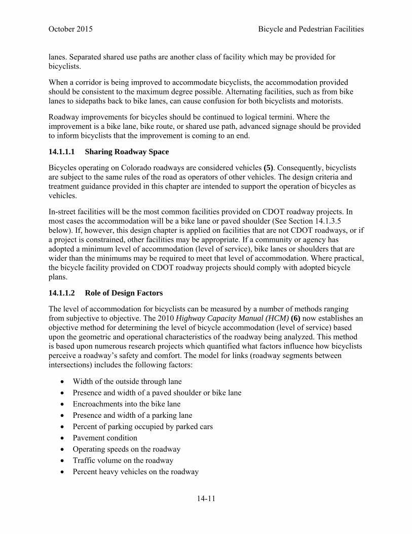
The level of accommodation for bicyclists can be measured by a number of methods ranging from subjective to objective. The 2010 Highway Capacity Manual (HCM) (6) now establishes an objective method for determining the level of bicycle accommodation (level of service) based upon the geometric and operational characteristics of the roadway being analyzed. This method is based upon numerous research projects which quantified what factors influence how bicyclists perceive a roadway’s safety and comfort. The model for links (roadway segments between intersections) includes the following factors:
Width of the outside through lane
Presence and width of a paved shoulder or bike lane
Encroachments into the bike lane
Presence and width of a parking lane
Percent of parking occupied by parked cars
Pavement condition
Operating speeds on the roadway
Traffic volume on the roadway
Percent heavy vehicles on the roadway
Bicycle and Pedestrian Facilities October 2015
14-12
The primary geometric conditions that are influenced by design are the width of the outside lane, the presence of a paved shoulder or bike lane, the width of the paved shoulder or bike lane, and encroachments into the bike lane or shoulder. As stated above in Section 14.1.1.1, on new CDOT construction projects, it is likely that shoulders and bike lanes will be the facility of choice for accommodating bicycles. However, in some cases a shared lane, or wide outside through lane, may be adequate to accommodate bicyclists. On some projects pavement cannot be widened or restriped to provide shoulder or bike lane width. On these roads, the available roadway space and traffic conditions should be analyzed to determine if the minimum adopted level of service for bicycles can be achieved by adjusting lane widths to provide wide curb lanes.
14.1.1.3 The Bicycle as a Design Vehicle
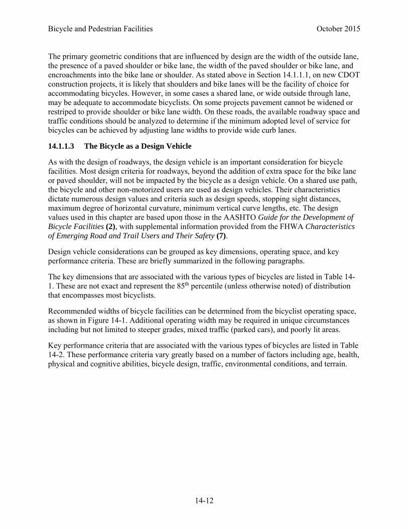
As with the design of roadways, the design vehicle is an important consideration for bicycle facilities. Most design criteria for roadways, beyond the addition of extra space for the bike lane or paved shoulder, will not be impacted by the bicycle as a design vehicle. On a shared use path, the bicycle and other non-motorized users are used as design vehicles. Their characteristics dictate numerous design values and criteria such as design speeds, stopping sight distances, maximum degree of horizontal curvature, minimum vertical curve lengths, etc. The design values used in this chapter are based upon those in the AASHTO Guide for the Development of Bicycle Facilities (2), with supplemental information provided from the FHWA Characteristics of Emerging Road and Trail Users and Their Safety (7).
Design vehicle considerations can be grouped as key dimensions, operating space, and key performance criteria. These are briefly summarized in the following paragraphs.
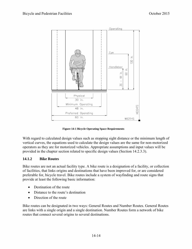
The key dimensions that are associated with the various types of bicycles are listed in Table 14-1. These are not exact and represent the 85th percentile (unless otherwise noted) of distribution that encompasses most bicyclists.
Recommended widths of bicycle facilities can be determined from the bicyclist operating space, as shown in Figure 14-1. Additional operating width may be required in unique circumstances including but not limited to steeper grades, mixed traffic (parked cars), and poorly lit areas.
Key performance criteria that are associated with the various types of bicycles are listed in Table 14-2. These performance criteria vary greatly based on a number of factors including age, health, physical and cognitive abilities, bicycle design, traffic, environmental conditions, and terrain.

October 2015 Bicycle and Pedestrian Facilities
14-13
Table 14-1 Key Dimensions of Bicycles
Table 14-2 Key Performance Criteria
User Type Feature Dimension
Typical upright adult bicyclist
Physical width (95th Percentile) 30 in. Physical length 70 in.
Physical height of handlebars (typical dimension)
44 in.
Eye height 60 in. Center of gravity (approximate) 33-44 in.
Operating width (minimum) 48 in. Operating width (preferred) 60 in. Operating height (minimum) 100 in. Operating height (preferred) 120 in.
Recumbent bicyclist Physical Length 82 in.
Eye height 46 in. Tandem bicyclist Physical length (typical dimension) 96 in.
Bicyclist with child trailer
Physical width 30 in. Physical length 117 in.
Hand bicyclist Eye height 34 in. Inline skater Sweep width 60 in.
Bicyclist Type Feature Value Typical upright adult bicyclist Speed, paved level terrain 8 - 15 mph
Speed, downhill 20 - 30 plus mph Speed, uphill 5 - 12 mph
Perception reaction time 1 - 2.5 seconds Acceleration rate 1.5 - 5 ft/s2
Coefficient of friction for braking, dry level pavement
0.32
Deceleration rate (dry level pavement) 15 ft/s2 Deceleration rate for wet conditions (50-
80% reduction in efficiency) 8 - 10 ft/s2
Recumbent bicyclist Speed, level terrain 11 - 18 mph Acceleration rate 3 - 6 ft/s2 Deceleration rate 10 - 13 ft/s2
Bicycle and Pedestrian Facilities October 2015
14-14
With regard to calculated design values such as stopping sight distance or the minimum length of vertical curves, the equations used to calculate the design values are the same for non-motorized operators as they are for motorized vehicles. Appropriate assumptions and input values will be provided in the chapter section related to specific design values (Section 14.2.3.3).
14.1.2 Bike Routes
Bike routes are not an actual facility type. A bike route is a designation of a facility, or collection of facilities, that links origins and destinations that have been improved for, or are considered preferable for, bicycle travel. Bike routes include a system of wayfinding and route signs that provide at least the following basic information:
Destination of the route
Distance to the route’s destination
Direction of the route
Bike routes can be designated in two ways: General Routes and Number Routes. General Routes are links with a single origin and a single destination. Number Routes form a network of bike routes that connect several origins to several destinations.
Figure 14-1 Bicycle Operating Space Requirements

October 2015 Bicycle and Pedestrian Facilities
14-15
14.1.2.1 General Bike Routes
General Routes connect users to destinations within a community. Typical destinations include the following:
Attraction Areas (i.e. stadiums, parks, etc.)
Neighborhood Areas (i.e. downtown, historic neighborhoods, etc.)
Trail Networks or trailheads (i.e. Glenwood Canyon Trail)
BICYCLE GUIDE signs may be provided along designated bicycle routes to inform bicyclists of bicycle route direction changes and to confirm route direction, distance, and destination. Typical signs that convey the basic wayfinding information for general routes are shown below in Figure 14-2. The MUTCD provides a number of different types of signs that can be used to provide guidance along bike routes. Some of these are shown below.
14.1.2.2 Numerically Labeled Bike Routes
Some communities may implement a numerically labeled system of bike routes. These routes should be designated using BIKE ROUTE signs (Figure 14-3). BICYCLE ROUTE signs can be customized by adding a specific community logo in the upper portion of the ellipse.
Figure 14-2 Examples of BICYCLE GUIDE Signs
Figure 14-3 Examples of BIKE ROUTE Signs

Bicycle and Pedestrian Facilities October 2015
14-16
A subset of numerically labeled bike routes is the U.S. Bicycle Route system. Where a designated bicycle route extends through two or more states, a coordinated submittal by the affected states for an assignment of a U.S. Bicycle Route number designation is sent to the American Association of State Highway and Transportation Officials (AASHTO) (8). A system of proposed U.S. Bicycle Routes is being developed. Colorado has not yet defined its U.S. Bicycle Routes; however, the AASHTO task force leading this effort has proposed several corridors through Colorado. For these routes the U.S. BIKE ROUTE (Figure 14-4) sign should be used to designate the routes.
14.1.3 Shared lanes
A shared lane is a lane of a traveled way that is open to bicycle travel and vehicular use. In this Roadway Design Guide it refers to a lane of less than 14 feet in width. Lanes 14 feet wide or wider are considered wide curb lanes.
The Highway Capacity Manual method can be used to determine what accommodations are necessary to meet a minimum level of accommodation for bikes along a bike route. On local roadways with low volumes and speeds, a shared lane may be all that is needed to comfortably accommodate bicyclists. On other roadways, a higher level of accommodation might be desirable; however, it may be infeasible to provide bike lanes or paved shoulders, or to adjust lane widths to provide a wide curb lane. In these latter cases the following potential traffic control devices could be considered, particularly if the roadways are identified as priority routes in an adopted bicycle plan:
14.1.3.1 Bicycle May Use Full Lane Sign (R4-11)
The BICYCLE MAY USE FULL LANE sign (R4-11) may be used on roadways where the lanes are too narrow for bicyclists and motorists to operate side by side within a single lane (9). On roadways with significant volumes, following motorists would likely be delayed while waiting for a gap to pass the bicyclist. On such roadways, the BICYCLE MAY USE FULL LANE sign should be considered to inform users that bicyclists have the legal right to claim the lane if the right-
Figure 14-4 U.S. BIKE ROUTE Sign

October 2015 Bicycle and Pedestrian Facilities
14-17
hand lane available for traffic is not wide enough to be safely shared with motor vehicles (10). Guidance on the BICYCLE MAY USE FULL LANE sign is provided in the MUTCD.
A SHARED LANE MARKING (see Section 14.1.2.2.1) may be used in conjunction with the BICYCLES MAY USE FULL LANE sign.
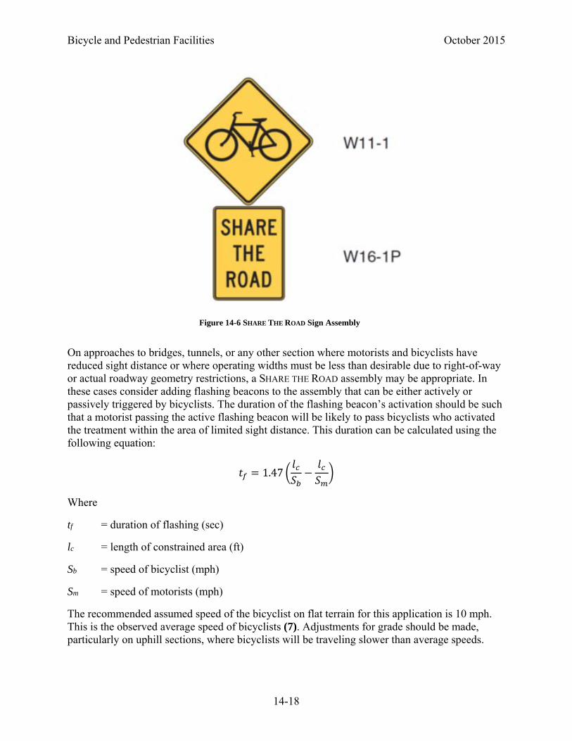
14.1.3.2 SHARE THE ROAD Sign Assembly (W11‐1 + W16‐1P)
In situations where there is a need to warn drivers to watch for bicycles traveling along the highway, the SHARE THE ROAD sign assembly may be considered (see Figure 14-6).
The SHARE THE ROAD sign assembly may be installed on State-maintained roadways at the discretion of each region’s Traffic Engineer. To have maximum effect, these signs should be used with discretion. Consideration for placement should be given where:
A relatively high number of cyclists can be expected on the roadway
The roadway cannot be improved for cyclists
The road narrows for a short distance and a motorist and bicyclist may unexpectedly find themselves using the same roadway such as at the end of a bike lane or bridge approach
There has been a significant history of bicycle crashes.
In addition to these reasons, the Share the Road sign assembly may be appropriate where (11):
Designated bicycle trails that are placed on short stretches of a major roadway that has not been improved for bicycling
Roadway where a known conflict problem exists
Roadway sections adjacent to shared use paths where some bicyclists choose to ride on the roadway
Figure 14-5 Bicycles May Use Full Lane Sign
Bicycle and Pedestrian Facilities October 2015
14-18
On approaches to bridges, tunnels, or any other section where motorists and bicyclists have reduced sight distance or where operating widths must be less than desirable due to right-of-way or actual roadway geometry restrictions, a SHARE THE ROAD assembly may be appropriate. In these cases consider adding flashing beacons to the assembly that can be either actively or passively triggered by bicyclists. The duration of the flashing beacon’s activation should be such that a motorist passing the active flashing beacon will be likely to pass bicyclists who activated the treatment within the area of limited sight distance. This duration can be calculated using the following equation:
1.47
Where
tf = duration of flashing (sec)
lc = length of constrained area (ft)
Sb = speed of bicyclist (mph)
Sm = speed of motorists (mph)
The recommended assumed speed of the bicyclist on flat terrain for this application is 10 mph. This is the observed average speed of bicyclists (7). Adjustments for grade should be made, particularly on uphill sections, where bicyclists will be traveling slower than average speeds.
Figure 14-6 SHARE THE ROAD Sign Assembly

October 2015 Bicycle and Pedestrian Facilities
14-19
A SHARED LANE MARKING (see Section 14.1.2.2.3) may be used in conjunction with the SHARE
THE ROAD sign assembly.
14.1.3.3 Shared Lane Markings
SHARED LANE MARKINGS (Figure 14-7) are intended to perform any of several functions (12):
Assist bicyclists with lateral positioning in a shared lane with on-street parallel parking in order to reduce the chance of a bicyclist impacting the open door of a parked vehicle
Assist bicyclists with lateral positioning in lanes that are too narrow for a motor vehicle and a bicycle to travel side by side within the same traffic lane
Alert road users of the lateral location bicyclists are likely to occupy within the traveled way
Encourage safe passing of bicyclists by motorists
Reduce the incidence of wrong-way bicycling
Refer to the MUTCD for proper placement of SHARED LANE MARKINGS.
SHARED LANE MARKINGS are not intended as a replacement for bike lanes. They should not be considered such even on constrained facilities. On higher speed roadways (> 35 mph) they may not be as effective as on lower speed roadways, bike lanes should be provided instead. If used on a bike route, additional improvements such as traffic calming or signal improvements should be considered for implementation in conjunction with SHARED LANE MARKINGS.
14.1.4 Wide Curb Lanes
In restricted urban conditions, where it is not possible to include bike lanes or paved shoulders or on lower volume, lower speed collector streets, a wide curb lane can help accommodate both
Figure 14-7 SHARED LANE MARKING

Bicycle and Pedestrian Facilities October 2015
14-20
bicycles and motor vehicles in the same lane. The Highway Capacity Manual (HCM) established methods can be used to identify the minimum wide curb lane width that will meet a target level of accommodation. Fourteen feet is the recommended minimum lane width for a wide curb lane, and within which a motorist may safely pass a bicyclist without encroaching into an adjacent lane.
The SHARED LANE MARKING and/or SHARE THE ROAD assembly may be used in wide curb lanes.
14.1.5 Paved Shoulders
Including paved shoulders during roadway construction, adding paved shoulders to an existing roadway without curb and gutter, or restriping a roadway to obtain a paved shoulder outside the travel lane can be an effective and relatively inexpensive way to improve a roadway for bicyclists. Gravel shoulders are not acceptable as bicycle facilities. Adding or widening of paved shoulders may be subject to Municipal Separate Storm Sewer System (MS4) permitting requirements which could substantially increase retrofit costs.
To accommodate bicyclists, paved shoulders at least 4 feet wide should be provided. Table 4-1 Geometric Design Standards (in Chapter 4) provides CDOT’s minimum standard shoulder widths.
14.1.5.1 Additional Width
Some jurisdictions may have adopted a minimum paved shoulder width above those required for Type C or D roadways (as shown in Figures 4-1 through 4-4, in Chapter 4) within their bicycle master plans. When these local shoulder widths exceed the planned or typical CDOT shoulder for this type of location, the project manager should consider accommodating local requirements when additional funding is provided by the local community to supplement the available budget.
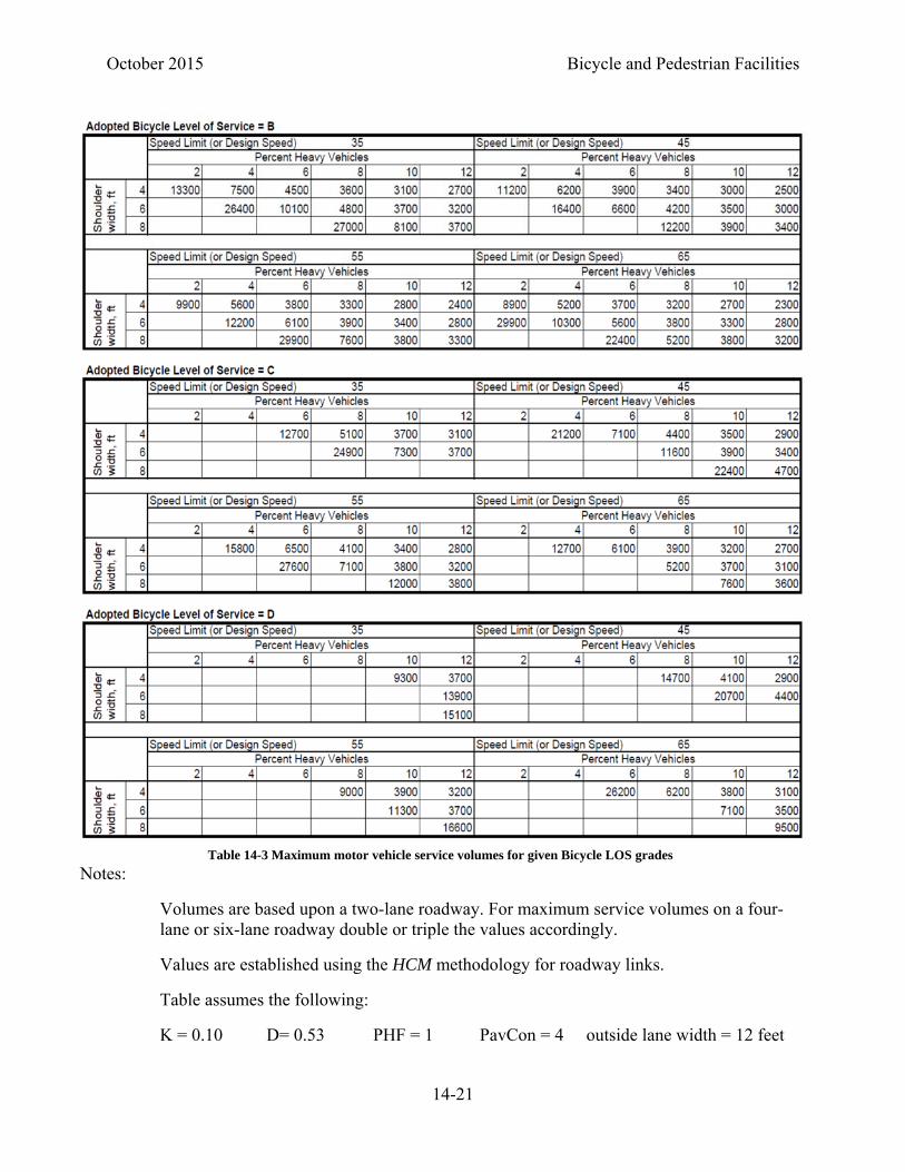
Other communities or agencies may have adopted a minimum bicycle Level of Service that is to be met on their roadways. CDOT projects within these jurisdictions should be designed to meet the adopted minimum bicycle Level of Service unless the available budget prohibits this action. Table 14-3 uses the aforementioned HCM method to provide the maximum design daily traffic for which a given shoulder width can provide a given bicycle Level of Service. For a given speed limit, percent heavy vehicles, and shoulder width, Table 14-3 provides the maximum number roadway AADT that will provide a selected bicycle Level of Service.
Scenic Byways plans for roadways may also specify wider shoulders. These plans should be accommodated during design.
October 2015 Bicycle and Pedestrian Facilities
14-21
Notes:
Volumes are based upon a two-lane roadway. For maximum service volumes on a four-lane or six-lane roadway double or triple the values accordingly.
Values are established using the HCM methodology for roadway links.
Table assumes the following:
K = 0.10 D= 0.53 PHF = 1 PavCon = 4 outside lane width = 12 feet
Table 14-3 Maximum motor vehicle service volumes for given Bicycle LOS grades

Bicycle and Pedestrian Facilities October 2015
14-22
14.1.5.2 Shoulders on Steep Grades
The additional effort required of bicyclists riding uphill frequently results in their having a greater side-to-side sweep width than those riding on a flat roadway. A bicyclist riding downhill may also need additional space to maintain a comfortable distance from the edge of the pavement and potential adjacent motorists. Consequently, on roadways with significant grades, or long grades, shoulders of 6 feet or greater width should be provided.
14.1.5.3 Rumble Strips
Where appropriate, rumble strips should be installed per CDOT Standard Plan No. M-614-1. On roadways identified as bicycle routes continuous rumble strips shall not be used. Rumble strips shall not be installed on shoulders less than 6 feet wide when guardrail is placed at the edge of the shoulder.
Rumble strips should be placed as closely as possible to the right edge of the roadway edge line. A minimum of 4 feet clear shoulder should be provided to the right of the rumble strips. A warning marking as shown in Figure 14-8 should be placed in advance of each rumble strip installation.
14.1.5.4 Shoulders at Intersections
At intersections with right-turn lanes, a paved shoulder is typically continued along the outside of the right turn lane. Some through bicyclists may continue to ride along the shoulder even though it compromises their safety at the intersection. Consequently, a 4-foot minimum space (bike slot) should be striped between the right-turn lane and the through lanes. This is illustrated in Figure 14-9.
Figure 14-8 Advance Warning Stripe for Rumble Strips

October 2015 Bicycle and Pedestrian Facilities
14-23
14.1.6 Bike Lanes
Bike lanes are lanes that have been designated with pavement markings for the preferential use of bicyclists. They are typically one-way facilities located to the right of the general travel lanes on both sides of two-way streets. They may be placed on the left side of one-way streets if predominant travel paths or conflict points suggest this is a desirable option.
14.1.6.1 Bike Lane Width
The minimum bike lane width on a roadway with no curb and gutter is 4 feet. On roadway with curb and gutter, the minimum width of a bike lane is five feet measured from the face of curb. If a 2-foot gutter is used a 6-foot bike lane measured to the face of curb is recommended. As with paved shoulders (Section 14.1.2.5), adopted bicycle plans and Scenic Byway plans should be consulted to determine if wider bike lanes are specified or if a wider bike lane is needed to meet an adopted Level of Service standard.
On roadways with narrow parking lanes, wider bike lanes (six or seven feet wide) should be considered. This allows more space for bicyclists to avoid potential opening car doors. On roadways with on-street parking where there is high parking turnover 13 feet minimum is recommended between the face of curb and the left side of the bike lane.
On roadways where significant volumes of bicyclists are expected, creating a potential need for passing maneuvers, six- or eight-foot bike lanes should be considered.
Wide shoulders or bike lanes may be interpreted by motorists as additional general purpose travel lanes or parking lanes. This can be discouraged through the use of designated or buffered bike lanes (Section 14.1.6.5).
Figure 14-9 Bike slot at intersection.

Bicycle and Pedestrian Facilities October 2015
14-24
As with paved shoulders, additional width should be considered on roadways with significant or long grades. Another option on significant grades is to remove the bike lane on the downhill side of the road, reducing but not eliminating the shoulder, and to install BICYCLE MAY USE FULL
LANE signs (R4-11) and SHARED LANE MARKINGS. The additional space gained from removing the bike lane on the downhill side of the road should be used to increase the bike lane width on the uphill side of the road.
14.1.6.2 Designating Bike Lanes
Bike lanes shall be designated with the bicycle symbol with the directional arrow being optional (Figure 14-10). Although using the directional arrow is optional, it’s strongly encouraged to better communicate the requirement for bicyclists to ride with traffic as the law requires.
Bicycle lane markings should be placed after intersections and major driveways. In rural areas the maximum spacing of bike lane markings should not exceed 1320 feet. In urban areas the spacing should not exceed 600 feet.
The 6 inch white stripe on the left of the bike lane should become a dotted (2-foot line with a 4-foot gap) at improved bus stops with alighting pads to clarify that buses are to move right to allow transit riders to disembark off of the roadway.
14.1.6.3 Contraflow Bike Lanes
A contraflow bicycle lane is an area of the roadway designated to allow bicyclists to travel in the opposite direction of traffic on a roadway that restricts motor vehicle travel to one direction.
Figure 14-10 Detail of Bike Lane Designation

October 2015 Bicycle and Pedestrian Facilities
14-25
These may be used to make convenient connections for bicyclists along otherwise one-way streets. If used, a contraflow bicycle lane should be marked so that bicyclists in the contraflow lane travel on their right-hand side of the road.
Where used, a contraflow bicycle lane shall be separated from opposite-direction travel by use of a solid double yellow center line marking, or a painted or raised median island (Figure 14-11).
The minimum contraflow bike lane width on a roadway with no curb and gutter is 4 feet. On roadway with curb and gutter, the minimum width of a contraflow bike lane is 5 feet measured from the face of curb. If a 2-foot gutter is used a 6 foot bike lane measured to the face of curb is recommended.
Where intersection traffic controls along the street exist (e.g., stop signs, flashing light signals or traffic signals) appropriate devices shall be oriented toward bicyclists in the contraflow lane. At speeds greater than 40 mph, a raised separator or painted buffer area should be used to separate the contraflow bicycle lane from the opposing travel lanes. At locations where a contraflow bicycle lane is provided across an intersection or a driveway entrance, pavement markings that inform intersection or driveway traffic of the presence of the bicycle facility and the direction of permitted bicycle traffic may be placed within the contraflow bicycle lane across the intersection or driveway opening.
ONE WAY (R6-1 or R6-2) signs should not be used where signs are provided to regulate turns from streets or driveways that intersect with a roadway that has a contraflow bicycle lane. TURN
PROHIBITION signs (R3-1 or R3-2) with a supplemental message EXCEPT BICYCLES (or the word EXCEPT over the bicycle symbol) plaques should be used. If DO NOT ENTER signs (R5-1) are used, an EXCEPT BICYCLES plaque should be placed under the DO NOT ENTER sign.
A bicycle lane for travel in the same direction as the general purpose lanes may be relocated from the right side of the roadway to the left side of the general purpose travel lanes.

Bicycle and Pedestrian Facilities October 2015
14-26
14.1.6.4 Bike Lanes at Driveways and Intersections
In Colorado, bicycles are vehicles and are required to follow the rules of the roadway when riding on the street (5). Consequently, the striping and marking of bike lanes at intersections should support the operations of bicycles as vehicles, and the safe mixing of bicyclists with motorists at conflict points such as driveways and intersections.
Bicyclists are required to ride on the right hand side of the rightmost lane that is intended for the direction they are traveling. Bicyclists may use left and right turn lanes when making the respective movements. Bicyclists are not required to ride at the right edge of the pavement; they may move left when passing slower vehicles, to make a left turn, or to avoid debris or obstacles on the pavement (10).
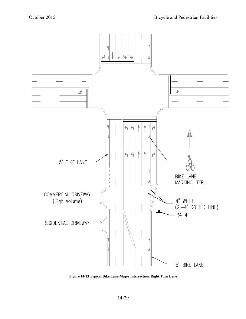
For both motor vehicles and bicycles the approach to a right turn and a right turn shall be made from as close as practicable to the right-hand curb or edge of the roadway (14). Prior to moving into a bike lane to make a right turn, motorists must yield to bicyclists who. To support crossing a bike lane at a right turn the bike lane striping is either terminated or becomes dotted on the approach to the intersection. The purpose of a solid white line is to discourage motorists from crossing the line. Changing the line pattern to a dotted line makes the striping appropriate for the required behaviors (15). It also informs the bicyclists that they are entering a potential conflict area. The length of the dotted line can be varied based upon the speed of the approaching roadway. A minimum 50-foot dotted line (or gap in the bike lane) should be provided; this is based upon a 1:12 taper rate, and a 4-foot bike lane. An 18:1 taper rate or 24:1 taper rate (75-ft and 100-ft) or longer dotted length of bike lane can be used on higher speed roadways.
When motorists cross a bike lane to move into a right turn lane, motorists are required to yield the right of way to bicyclists in the bike lane (21). This means the use of the BEGIN RIGHT TURN
LANE YIELD TO BIKES sign (R4-4) is appropriate when it’s added to a roadway where a turn lane
Figure 14-11 Example Contraflow Bicycle Lane Markings

October 2015 Bicycle and Pedestrian Facilities
14-27
is developed (Figure 14-13, Figure 14-17, Figure 14-18, and Figure 14-20). However, in the trap lane condition (Figure 14-15), the through bicyclists must cross the motorists’ path to continue through the intersection. In this case the bicyclists must yield to the motorist before moving left; therefore the R4-4 is not appropriate in these conditions.
On retrofit projects, it may not be possible to include bike lanes through existing intersections with turn lanes. On such projects the bike lane should be terminated in advance of the intersection and SHARED LANE MARKINGS should be considered for the left side of the right turn lane. An example of this marking is shown in Figure 14-26 in the buffered bike lanes section.
In locations with significant numbers of right turning bicyclist, an additional bike lane for right turning bicyclist can be provided. The installation of right turn bike lanes may be considered at high volume high speed right turn lanes. These bike lanes should include right turn arrows and the text message ONLY.
By riding in the roadway in a predictable and consistent manner bicyclists are more visible to motorists. This increased visibility has been shown to reduce crashes when compared to riding on a sidewalk or pathway next to the roadway (16, 17, 18, 19, 20).
14.1.6.4.1 Bike Lanes at Continuous Flow Intersections
At continuous flow intersections a bike lane is provided for through bicyclists. Two options are available for left turning bicyclists:
Left turning bicyclists may ride through the intersection or in the left turn lanes. Additional bike lanes for left turning cyclists may be considered.
Left turning bicyclists may make two consecutive through movements obeying all traffic control devices (23). A staging area for the bicyclists to wait between through movements should be provided for bicyclists making this maneuver.
Dedicated right turn lanes for bicyclists should be considered at continuous flow intersections.

Bicycle and Pedestrian Facilities October 2015
14-28
Figure 14-12 Typical Bike Lane-Major Intersection, No Right Turn Lane- Curb and Gutter
October 2015 Bicycle and Pedestrian Facilities
14-29
Figure 14-13 Typical Bike Lane-Major Intersection. Right Turn Lane
Bicycle and Pedestrian Facilities October 2015
14-30
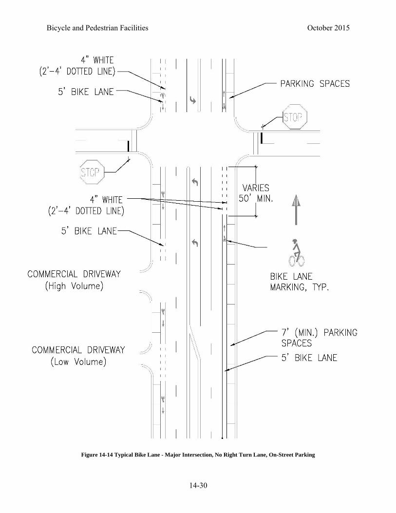
Figure 14-14 Typical Bike Lane - Major Intersection, No Right Turn Lane, On-Street Parking

October 2015 Bicycle and Pedestrian Facilities
14-31
Figure 14-15 Typical Bike Lane-Major Intersection. Right Turn Trap Lane-Bus Stop

Bicycle and Pedestrian Facilities October 2015
14-32
Figure 14-16 Typical Bike Lane-Tee Intersection. Right Turn Must Turn Right-Bus Stop

October 2015 Bicycle and Pedestrian Facilities
14-33
Figure 14-17 Typical Bike Lane-Tee Intersection. Right Turn Lane-Bus Bay

Bicycle and Pedestrian Facilities October 2015
14-34
Figure 14-18 Typical Bike Lane- Compact Interchange

October 2015 Bicycle and Pedestrian Facilities
14-35
Figure 14-19 Typical Bike Lane-Rural Interchange

Bicycle and Pedestrian Facilities October 2015
14-36
Figure 14-20 Typical Bike Lane-Continuous Flow Intersection

October 2015 Bicycle and Pedestrian Facilities
14-37
14.1.6.4.2 Two-Stage Turn Queuing Box
At some intersections, making a left turn by merging across traffic to a left turn lane, may be inconvenient, uncomfortable, or unsafe for bicyclists. The Colorado Revised Statutes (Section 42-4-1412(8)(a)) allows a bicyclist to turn left by merging to a left turn lane and turning just as any other vehicle, or by making a two-stage left turn as follows:
A person riding a bicycle or electrical assisted bicycle intending to turn left shall approach the turn as closely as practicable to the right-hand curb or edge of the roadway. After proceeding across the intersecting roadway to the far corner of the curb or intersection of the roadway edges, the bicyclist shall stop, as much as practicable, out of the way of traffic. After stopping, the bicyclist shall yield to any traffic proceeding in either direction along the roadway that the bicyclist had been using. After yielding and complying with any official traffic control device or police officer regulating traffic on the highway along which the bicyclist intends to proceed, the bicyclist may proceed in the new direction.1
Figure 14-21 Common Maneuvers for Bicyclists Turning Left at an Intersection

Bicycle and Pedestrian Facilities October 2015
14-38
A two-stage turn queuing box is a designated area at an intersection intended to provide bicyclists a place to wait before proceeding in a different direction of travel. It facilitates the two-stage turn described in the statutes. A two-stage turn queuing box should be located outside of the path of turning traffic so that it does not conflict with the right turn on red movement. A NO
TURN ON RED (R10-11) sign shall be installed where a two-stage turn queuing box is not located outside the path of right turning traffic. A two-stage turn queuing box should be located downstream of the crosswalk and stop line. A bicycle symbol should be placed in the two-stage turn queuing box oriented in the direction in which the bicyclists enter the box, along with an arrow showing the direction of turn, (Figure 14-22).
Passive detection of bicycles in the two-stage turn queuing box should be provided if detection is required to actuate the signal which allows bicyclists to cross. A two-stage turn queuing box is most commonly used for left turns, but it may be used for right turns from the left side of a one-way roadway. Green colored pavement may be used within the two-stage turn queuing box.
Two-stage bike boxes at an intersection are shown in Figure 14-23.
Figure 14-22 Two-Stage Left Turn Box

October 2015 Bicycle and Pedestrian Facilities
14-39
14.1.6.5 Buffered Bike Lanes
A buffered bicycle lane is a bicycle lane that is separated from the adjacent general-purpose lane or parking lane by a pattern of standard longitudinal markings. Buffered bike lanes appeal to a wider cross-section of bicyclists and: provide greater shy distance between traffic and bicyclists, reduce the possibility of a wide bicycle lane being misconstrued as a travel or parking lane, and delineate a space between a parking lane and an adjacent bicycle lane.
The buffer markings consists of two longitudinal white lines and may incorporate an interior diagonal cross hatch or chevron (Figure 14-24). These transverse markings shall be included when the buffer space is greater than 3 feet in width. The minimum buffer width should be no less than 18 inches. The spacing for transverse markings will vary based upon the speed of the adjacent roadway, on higher speed roadways less frequent hatching may be needed. The width of the buffer will vary depending upon such conditions as motor vehicle speed, percentage of heavy vehicles, roadway cross slopes, and desired level of accommodations of bicycles. Guidelines for buffered preferential lanes can be found in the MUTCD in section 3D-01. The FHWA Separated Bike Lane Planning and Design Guide and the National Association of City Transportaton
Figure 14-23 Example of Two-Stage Turn Queue Box at an Intersections.

Bicycle and Pedestrian Facilities October 2015
14-40
Officials (NACTO) Urban Bikeway Design Guide also offers further design guidance for buffered bicycle lanes (60)(61).
Buffered bicycle lanes may be considered anywhere a standard bicycle lane is being considered, and may be given special consideration for roadways that exhibit high volumes or travel speeds. In some locations it may be desirable to use less than the full space available for a bike lane. Such locations include sections of roadway where a wide bike lane might be perceived as on-street parking or another travel lane. In these locations a buffered bike lane may be considered. A buffered bike lane may be considered where a bike lane of six or more feet is being provided to meet a minimum level of accommodation.
A buffer can also be provided between a parking lane and a bike lane to reduce the potential for a bicyclists to ride in a parked cars door swing zone. A buffer area provides a greater separation between the bicycle lane and adjacent lanes than is provided by a single normal or wide lane line.
14.1.6.5.1 Buffered Bike Lanes at Intersections
Buffered bike lanes should be striped much as non-buffered bike lanes at intersections.
As described in Section 14.1.6.4 Bike Lanes at Driveways and Intersections, prior to intersections, the bike lane marking is discontinued or dotted to support the legal requirements for turning motorists and to help inform the bicyclists that they are entering a potential conflict area. At intersections where a dotted bike lane line would be used, consideration should be given to terminating the buffer between the bike lane and the general travel lanes. Figure 14-26 illustrates a buffered bike lane being used at an intersection where the buffer and bike lane width becomes a right turn lane.
Figure 14-24 Buffered Bike Lane

October 2015 Bicycle and Pedestrian Facilities
14-41
At locations where it is desirable to include a right turn lane, but there is not adequate cross section width to provide bike lanes and a right turn lane, SHARED LANE MARKINGS can be used to guide bicyclists to the left side of a designated right turn lane. This option should only be used where there is a receiving bike lane or shoulder on the far side of the intersection.
Figure 14-25 Detail of Typical Buffered Bike Lane Designation
Bicycle and Pedestrian Facilities October 2015
14-42
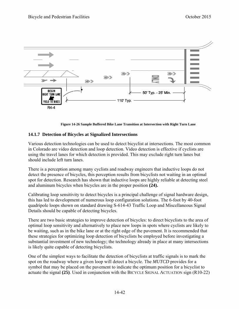
14.1.7 Detection of Bicycles at Signalized Intersections
Various detection technologies can be used to detect bicyclist at intersections. The most common in Colorado are video detection and loop detection. Video detection is effective if cyclists are using the travel lanes for which detection is provided. This may exclude right turn lanes but should include left turn lanes.
There is a perception among many cyclists and roadway engineers that inductive loops do not detect the presence of bicycles, this perception results from bicyclists not waiting in an optimal spot for detection. Research has shown that inductive loops are highly reliable at detecting steel and aluminum bicycles when bicycles are in the proper position (24).
Calibrating loop sensitivity to detect bicycles is a principal challenge of signal hardware design, this has led to development of numerous loop configuration solutions. The 6-foot by 40-foot quadripole loops shown on standard drawing S-614-43 Traffic Loop and Miscellaneous Signal Details should be capable of detecting bicycles.
There are two basic strategies to improve detection of bicycles: to direct bicyclists to the area of optimal loop sensitivity and alternatively to place new loops in spots where cyclists are likely to be waiting, such as in the bike lane or at the right edge of the pavement. It is recommended that these strategies for optimizing loop detection of bicyclists be employed before investigating a substantial investment of new technology; the technology already in place at many intersections is likely quite capable of detecting bicyclists.
One of the simplest ways to facilitate the detection of bicyclists at traffic signals is to mark the spot on the roadway where a given loop will detect a bicycle. The MUTCD provides for a symbol that may be placed on the pavement to indicate the optimum position for a bicyclist to actuate the signal (25). Used in conjunction with the BICYCLE SIGNAL ACTUATION sign (R10-22)
Figure 14-26 Sample Buffered Bike Lane Transition at Intersection with Right Turn Lane

October 2015 Bicycle and Pedestrian Facilities
14-43
(26) (see Figure 14-27), this symbol can eliminate the problem of bicycle detection for any intersection movement where the loops can detect bicyclists.
New loops should be of a type that will detect bicycles.
14.1.7.1 Signal Detection Loops in Bike Lanes
Changing lanes at an intersection to cause a signal change is not normal vehicular behavior, yet bicyclists are frequently required to do so. In the interest of providing consistent treatments between modes, bike lane detection should be considered at locations where signal change is unlikely without detection.
The recommended loop type for bike lanes is a quadripole loop of reduced size (2-foot x 10-foot). These loops are highly sensitive to objects in the area immediately above them, but detection falls off rapidly outside of this sensitivity field; this means that cars in adjacent lanes will not be detected.
14.1.7.2 Signal Timing for Bicycles
The MUTCD requires that signal timing and actuation on bikeways be reviewed and adjusted to consider the needs of bicyclists (27). Meeting the needs of bicyclists on bikeways means providing adequate minimum green times and adequate change periods.
The minimum green time allows bicyclists to start from a stopped condition, cross, and clear the intersection. For the crossing of narrow roadways, the bicyclists may not accelerate to full speed
Figure 14-27 Bike Detection Symbol and Bicycle Signal Actuation Sign

Bicycle and Pedestrian Facilities October 2015
14-44
before clearing the intersection. On wider roads, the bicyclist will accelerate to full speed and may require additional time to finish crossing and clear the intersections. The equations to calculate minimum green time are as follows:
1.0 1.15√ 6 Where W ≤ 72 feet
10.8.
Where W > 72 feet
and
Gmin = minimum green time (sec)
W = width of intersection (ft)
Typically the minimum change period is calculated using the following equation (28):
1.472 32.2 1.47
where:
CP = change period (yellow change plus red clearance intervals),(sec)
t = perception-reaction time to the onset of a yellow indication, s, assume 1 (sec)
v = approach speed (mph)(assume 10 MPH for a bicycle)
a = deceleration rate in response to the onset of a yellow indication, (ft/sec),(assume 5 ft/sec for a bicycle)
g = grade, with uphill positive and downhill negative (percent grade / 100),(ft/ft)
W = width of intersection (ft)
Lv = length of vehicle, (ft)(assume 6 ft for bicycle)
At wide intersections, the clearance interval provided for motorists may not be long enough to provide for bicyclists to clear the intersection. Advance loops in bike lanes or on shoulders can provide an extended green time to allow bicyclists to clear the intersection before the conflicting traffic gets a green signal. Alternatively, a supplemental bicycle specific signal (see Section 14.2.16.6.3 Bicycle Signals) with a supplement plaque stating BICYCLE SIGNAL could be provided for bicyclists.
At installations where visibility-limited signal faces are used, signal faces shall be adjusted so bicyclists for whom the indications are intended can see the signal indications. If the visibility-limited signal indications cannot be aimed to serve the bicyclist, then separate signal indications shall be provided for the bicyclist.

October 2015 Bicycle and Pedestrian Facilities
14-45
14.1.8 Bike Lanes at Roundabouts
Bike lanes are not carried through roundabouts. The MUTCD states that bike lane markings should stop at least 100 feet prior to the approach of a roundabout. Following the end of a bike lane, a pathway must be provided for bicyclists to exit the roadway, if they choose. A SHARED LANE MARKING may be used through the roundabout. Figure 14-28 is an example of a multi-lane roundabout.
Figure 14-28 Multi-lane Roundabout
Bicycle and Pedestrian Facilities October 2015
14-46
14.1.9 Separated Bike Lanes (Cycle track)
Separated bike lanes are bicycle lanes which are separate from general travel lanes and the sidewalk. They are not the same as shared use paths because they are bicycle-only facilities. They are distinct from buffered bike lanes because there is a physical separation, such as a raised island or parked cars, between the bicyclists and the outside travel lane. Operationally, they can be very challenging, particularly at intersections with driveways and streets.
For guidance on the design of cycle tracks refer to the FHWA document Separated Bike Lane Planning and Design Guide and the NACTO Urban Bikeway Design Guide.
14.1.10 Bicycle Boulevards
A bicycle boulevard is a local street or series of contiguous street segments that have been modified to provide enhanced accommodation for bicyclists while discouraging through automobile travel. Local motor vehicle access is maintained along the streets. Bicycle boulevards would not be implemented on CDOT roadways. However, they may be used to improve alternative routes (see Section 14.1.10).
Bicycle boulevards often make use of low volume, very low speed local streets. SHARED LANE
MARKINGS may be used along bike boulevards. Often bicycle boulevards include bicycle friendly traffic calming treatments (speed cushions, mini traffic circles) to reduce speeds of motor vehicles along the roadway. Some portions of a bike boulevard may be on busier roads with bike lanes. Through motor vehicle traffic can be discouraged using traffic diverters at intersections. Bicycle boulevards can be created by connecting the ends of cul de sac roadways with bikeways. At intersections the bicycle boulevard should be given priority over side streets. Additionally, since bike boulevards typically serve as bike routes, wayfinding signage should be provided.
One potential obstacle to implementing bike boulevards is the crossing of major roadways. Improvements to signal timing and detection or the provision of enhanced crossing treatments (activated beacons, raised medians) where no signals exist will make a bicycle boulevard more appealing to cyclists.
Another challenge related to bike boulevards can be frequent opposition voiced by those who live along the streets being altered. Other motorists who travel on the street may feel the same way because of altered travel patterns for the auto mode. Designers considering the implementation of a bike boulevard should be aware of these considerations and should accordingly plan for early and sustained public outreach to the project’s neighbors, communities and municipalities.
14.1.11 Alternative Routes
On some projects it may not be possible to improve the roadway to accommodate bicyclists. In these cases it may be possible to improve an adjacent street to provide an alternative route for bicyclists to access destinations that would be served by the primary project roadway. Alternative routes could potentially be improved using some of the treatments described in this chapter.

October 2015 Bicycle and Pedestrian Facilities
14-47
In addition to the accommodations provided along the alternative route, several other factors must be addressed when considering whether or not an alternative route provides a suitable accommodation for bicyclists:
Geometric delay - This is the delay caused to the bicyclists by increased distance they must travel to use the alternative route. If an alternative route significantly increases the distance and time a bicyclist must travel to access a destination it will be less likely to be used.
Control delay - This is the delay caused by the increasing the number of STOP signs or red traffic signals along a route. Often the primary corridor is given the majority of the green time at signals and does not often have to stop at minor street intersections. If the alternative route is a local street that must stop at every cross street and gets minimal green time at signalized intersections, bicyclists will be less likely to use it.
Access to destinations - An alternative route must provide access to the trip destinations along the primary corridor or it will not be a practical option for bicyclists.
Safety - Any alternative route being considered for improvement should be subject to a safety assessment. This would include reviewing crashes along the route as well as identifying potential safety concerns associated with accessing the primary project corridor from the alternative route.
14.1.12 Other Roadway Considerations
14.1.12.1 Roadway Cross Slope
The typical cross slopes provided for roadways will usually accommodate cyclists. Cross slopes of 5% or less are desirable for bicycles. However, the AASHTO Guide for the Development of Bicycle Facilities allows superelevation rates up to 8%.
14.1.12.2 Drainage Inlets and Utility Covers
Placement of drainage inlet grates should be avoided within a bicycle facility regardless of whether that facility is a bike lane, shoulder, or shared lane. If this is not possible, drainage inlet grates should be bicycle-safe. Utility covers and drainage grates should be installed to be flush with the pavement. The construction of new roadway facilities should consider the use of curb inlets as opposed to gutter pan drop inlets.
Drainage inlet grates with slots or gaps parallel to the roadway can trap a bicycle’s front wheel and seriously damage the bicycle or injure the cyclist. These types of grates should be replaced with bicycle-safe grates that maintain the required hydraulic capacity for the inlet (Figure 14-29). A bicycle-safe grate should have, at a minimum, bars perpendicular to the travel direction at a 4 inch center-to-center spacing
For safety considerations, any utility cover or drainage inlet located on a bicycle facility that has a gap or opening parallel to the roadway should be replaced or corrected as soon as possible. If a

Bicycle and Pedestrian Facilities October 2015
14-48
drop inlet with parallel slots cannot be replaced, an obstruction marking should be placed on the pavement prior to the inlet (Figure 14-30).
14.1.12.3 Railroad Crossings
Ideally travel ways should cross rail lines at right angles. The more the railroad crossing deviates from a right angle, the greater the potential for a cyclist’s front wheel to be trapped in the tracks, causing the loss of steering control and a crash. SKEWED CROSSING warning signs (W10-12) should be considered for the approach to the crossing.
A special treatment should be considered for railroad crossings with angles less than 45 degrees. It is recommended that a special path be provided for bicyclists to cross the tracks at a right angle. The simplest approach would be to provide a pavement widening at the crossing. Figure 14-31 shows two scenarios of potential skewed crossing treatments. Additionally, pavement markings can be provided to direct bicyclists to the preferred path of travel.
Figure 14-29 Bicycle Compatible Drainage Grates
Figure 14-30 Bicycle Obstruction Marking in Advance of a Drop Inlet

October 2015 Bicycle and Pedestrian Facilities
14-49
14.1.12.4 Bridges and Tunnels
The FHWA Design Guidance and Policy Statement (29) states: “A bridge that is likely to remain in place for 50 years should be built with sufficient width for safe bicycle and pedestrian use (sidewalks and shoulders) in anticipation that facilities will be available at either end of the bridge even if that is not currently the case. Design bridges with sidewalks and shoulders or bike lanes on both sides of the structure.” Tunnels should also be designed to accommodate bicyclists and pedestrians.
14.2 SHARED USE PATHS
Shared use paths are physically separated from motorized vehicular traffic by either a physical barrier or clear space. They are often on their own alignments but may be located within the right-of-way of an adjacent roadway.
Since shared use paths are intended for use by many modes (such as pedestrians, persons with disabilities, etc.) they must be made ADA compliant to the maximum extent feasible (see Section 14.3).
14.2.1 Surface Treatments
14.2.1.1 Paved Shared Use Path
Most CDOT shared use path projects will be paved. Asphalt and Portland cement concrete are the two most common surfaces for shared use paths. For rigid pavement design information, refer to the CDOT Pavement Design Manual. The Materials Engineer should be consulted for flexible pavement design information. On Portland cement concrete pavements, the transverse
Figure 14-31 Potential Treatments at a Skewed Railroad Crossing
Bicycle and Pedestrian Facilities October 2015
14-50
joints should be saw cut, rather than tooled, to provide for a smoother ride. Skid resistance should not be reduced, broom finish or burlap drag surfaces should be provided.
Where paved shared use paths cross unpaved roadways or driveways, the road or drive should be paved 20 feet on each side of the shared use path to help minimize debris accumulation on the path.
14.2.1.2 Unpaved Shared Use Paths
In areas where path use is expected to be primarily recreational, unpaved surfaces may be acceptable for shared use paths. Materials should be chosen to ensure the ADA requirements for a firm, stable, slip resistant surface are met. Even when meeting ADA criteria, some users such as in-line skaters, kick scooters, and skateboarders may be unable to use unpaved shared use paths.
On unpaved shared use paths, grades of greater than 3 percent may result in erosion problems and bicycle handling problems for some bicyclists. Additionally, snow plowing may be impractical on unpaved shared use paths.
14.2.2 Design Speed
As with roadways, the design speed selected for shared use paths dictates other design criteria (sight distance, curve alignments). Consequently, the selection of an appropriate design speed is important to maximize the flexibility of design when developing a shared use path.
Design speeds range from 12 to 30 mph. Two mph increments of design speed should be used for less than 20 mph, and 5 mph increments should be used above 20 mph.
An 18 mph design speed is generally sufficient for most paths in relatively flat areas (generally less than 2 percent grades). If it is expected that there will be significant use by recumbent bicyclists, the minimum design speed should be to 18 mph (7).
Design speeds lower than 18 mph may be used in areas where the expected riding population is anticipated to be made up of lower speed users such as children. A design speed of less than 14 mph should be used only in unusual circumstances. Justification based upon environmental context and user types should be provided when using a design speed less than 14 mph.
Lower design speeds may be used on the approach to roadway crossing points or hazards. Traffic control and geometric features should be used together to reduce speeds in these locations (see Section 14.2.10.6).
Where sustained grades exceeding 4 percent in excess of 300 feet in length are required, an increased design speed should be used. They should be based upon the anticipated travel speeds of cyclists traveling downhill. Thirty mph should be the maximum design speed used in all but the most unusual cases.
14.2.3 Sight Distance
As stated in Chapter 3 of this Roadway Design Guide, a critical element in assuring safe and efficient operation of a vehicle on a highway is the ability to see ahead. Sight distance is the

October 2015 Bicycle and Pedestrian Facilities
14-51
distance along a roadway or path throughout which an object of specified height is continuously visible to a bicyclist. In a vertical plane, this distance is dependent on the height of the bicyclist’s eye above the road or path surface, the specified object height above the road surface, and the height and lateral position of obstructions such as cut slopes, guardrail, and retaining walls within the bicyclists’ line of sight. Horizontal alignment, including the routing of a path around visual screens, can also impact sight distance and should be considered. Sight distance of sufficient length must be provided to allow a bicyclist to avoid striking unexpected objects in the traveled way.
14.2.3.1 Stopping Sight Distance
Stopping sight distance is the sum of two distances:
The distance a bicycle travels from the instant the bicyclist sights an object necessitating a stop to the instant the brakes are applied (brake reaction distance), and
The distance required to stop the bicycle from the instant brake application begins (braking distance).
Stopping sight distance is measured from the bicyclist’s eyes, which are assumed to be 4.5 feet above the pavement, to an object flush with the surface of the shared use path. If it is found that a significant number of recumbent cyclists are represented in the local cycling population, an eye height of 2.8 feet should be used (7). Distances greater than the minimum stopping sight distance provide an additional measure of safety and should be considered where practical.
On downhill grades, gravity acts against braking forces and increases the distance required to stop. On uphill grades gravity reduces the distance required to stop. The effect of grades is represented in stopping sight distance values.
The equation for stopping sight distance, assuming a 2.5 second reaction time, is
3.6730
Where,
S = stopping sight distance (ft)
V = design speed (mph)
f = friction factor (assume 0.16 for a typical bicycle)
G = grade in (ft/ft)
Table 14-4 shows sight distances for level roadways and roadways with grade for various design speeds. See also Chapter 3 for adjustments for grades.
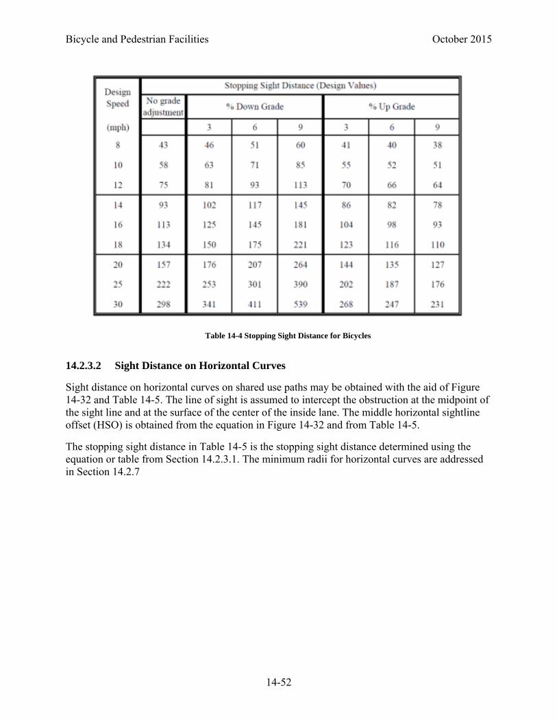
Bicycle and Pedestrian Facilities October 2015
14-52
14.2.3.2 Sight Distance on Horizontal Curves
Sight distance on horizontal curves on shared use paths may be obtained with the aid of Figure 14-32 and Table 14-5. The line of sight is assumed to intercept the obstruction at the midpoint of the sight line and at the surface of the center of the inside lane. The middle horizontal sightline offset (HSO) is obtained from the equation in Figure 14-32 and from Table 14-5.
The stopping sight distance in Table 14-5 is the stopping sight distance determined using the equation or table from Section 14.2.3.1. The minimum radii for horizontal curves are addressed in Section 14.2.7
Table 14-4 Stopping Sight Distance for Bicycles

October 2015 Bicycle and Pedestrian Facilities
14-53
Figure 14-32 Stopping Sight Distance on a Shared Use Path Horizontal Curve

Bicycle and Pedestrian Facilities October 2015
14-54
14.2.3.3 Sight Distance on Vertical Curves
Sight distance on vertical curves is required to allow bicyclists to see objects on the path over the crest of vertical curves or obstacles that are located beyond overhanging visual obstructions on sag vertical curves. The method of calculating sight distance for bicyclists on vertical curves is essentially the same as that used for calculating the sight distance for motorists (Section 3.1.5 Sight Distance on Vertical Curves); however, the height of eye and object height need to be modified for bicycle specific values. Stopping sight distance is measured when the eye height
Table 14-5 Minimum Horizontal Clearance for Horizontal Sightline Offset for Horizontal Curves

October 2015 Bicycle and Pedestrian Facilities
14-55
and the height of the object are 4.5 feet (for a typical bicycle rider) and 0 feet (flush with the pavement surface) respectively.
When S is less than L,
30
When S is greater than L,
22025
Where,
S = stopping sight distance (ft)
L = length of crest vertical curve (ft)
A = algebraic difference in grades (%)
Table 14-6 Minimum Length of Crest Vertical Curve Based on Stopping Sight Distance is used to select the minimum length of vertical curve necessary to provide minimum stopping sight distance at various speeds on crest vertical curves. Note that this table is for regular bicycles. For recumbent bicycles the values would need to be recalculated using equations 3-14 and 3-42 in the PGDSH ) ) (1).
Figure 14-33 Sight Distance on Crest Vertical Curves
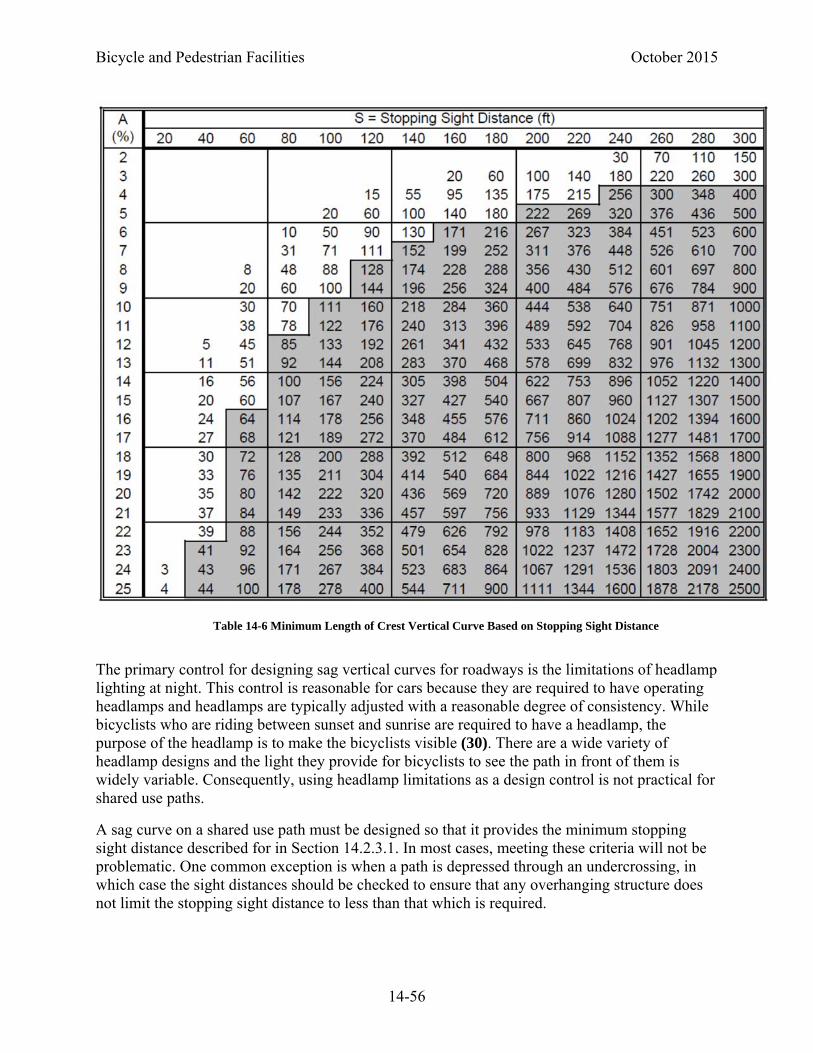
Bicycle and Pedestrian Facilities October 2015
14-56
The primary control for designing sag vertical curves for roadways is the limitations of headlamp lighting at night. This control is reasonable for cars because they are required to have operating headlamps and headlamps are typically adjusted with a reasonable degree of consistency. While bicyclists who are riding between sunset and sunrise are required to have a headlamp, the purpose of the headlamp is to make the bicyclists visible (30). There are a wide variety of headlamp designs and the light they provide for bicyclists to see the path in front of them is widely variable. Consequently, using headlamp limitations as a design control is not practical for shared use paths.
A sag curve on a shared use path must be designed so that it provides the minimum stopping sight distance described for in Section 14.2.3.1. In most cases, meeting these criteria will not be problematic. One common exception is when a path is depressed through an undercrossing, in which case the sight distances should be checked to ensure that any overhanging structure does not limit the stopping sight distance to less than that which is required.
Table 14-6 Minimum Length of Crest Vertical Curve Based on Stopping Sight Distance
October 2015 Bicycle and Pedestrian Facilities
14-57
14.2.3.4 Sight Distance at Intersections
The discussion on intersection sight distance provided in Chapter 9 of this Roadway Design Guide is also applicable to shared use paths. Also applicable are the procedures to determine sight distances at intersections presented in Chapter 9 of the PGDHS) (1), using the appropriate design speed for the shared use path approaches to the intersection, for each of the cases below:
Case A --Intersections with no control (not typically used on shared use paths)
Case B -- Intersections with stop control on the minor road
Case B3 – Crossing maneuver from the minor road
Case C – Intersections with yield control on the minor road
Case C1 – Crossing maneuver from the minor road
Case D – Intersections with traffic signal control
Checking the sight distances for vehicles turning onto or off of the shared use path is typically not necessary. The minor roadway may be either the shared use path or the roadway.
14.2.4 Shared Use Path Width
The minimum width of pavement for a two-directional shared use path is 10 feet.
Additional width may be appropriate depending on the volume of users and mix of users on the shared use path. The FHWA has developed a level of service shared use path calculator which may be helpful in determining the appropriate width for a path based on the relative number of users expected (31, 32). Pathways of up to 14 feet are recommended in locations that are anticipated to have high volumes (greater than 300 users in the peak hour), or with a high percentage of pedestrians (greater than 30 percent). An 11 foot shared use path will allow for a bicyclist to pass another traveling in the same direction at the same time a someone is approaching from the opposite direction (31). Wider paths should be considered where there is expected significant use by in-line skaters, hand cyclists, adult tricyclists (7), or on steep grades and through curves.
A reduced width, to as little as 8 feet, may be used only for short sections of constrained conditions and where the following conditions apply:
Bicycle traffic is expected to be low, even on peak days or during peak hours
Pedestrian use of the facility is not expected to be more than occasional
Horizontal and vertical alignments provide safe and frequent passing opportunities, and
The path will not be regularly subjected to maintenance vehicle loading conditions that would cause pavement edge damage.
In most cases it is not necessary to designate separate space for different users on shared use paths. Slower path users tend to keep right while higher speed users pass on the left. If additional
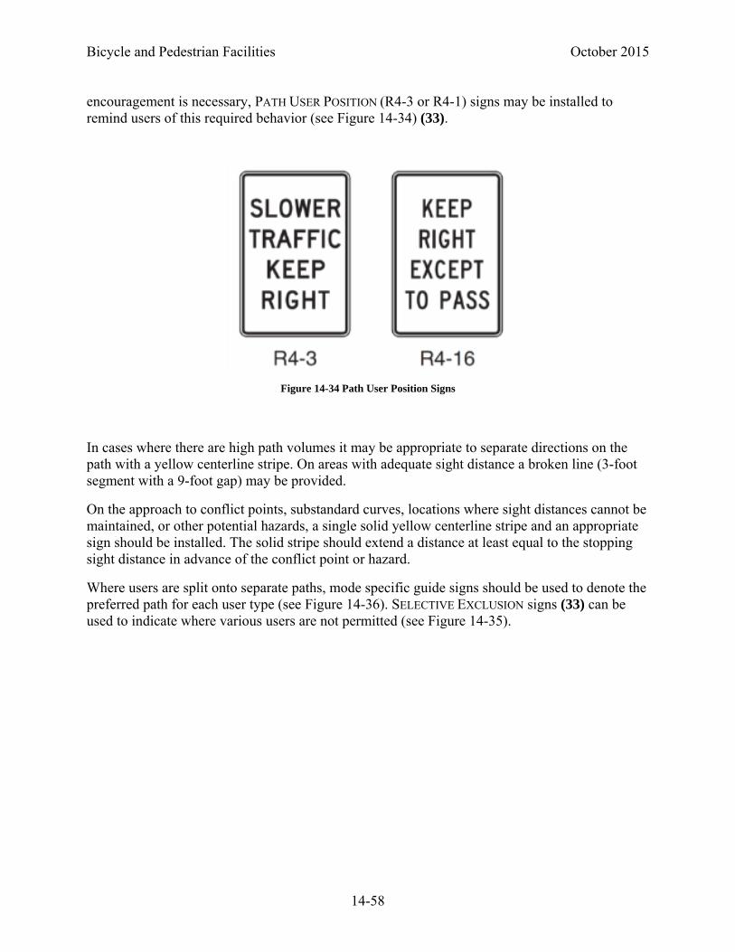
Bicycle and Pedestrian Facilities October 2015
14-58
encouragement is necessary, PATH USER POSITION (R4-3 or R4-1) signs may be installed to remind users of this required behavior (see Figure 14-34) (33).
In cases where there are high path volumes it may be appropriate to separate directions on the path with a yellow centerline stripe. On areas with adequate sight distance a broken line (3-foot segment with a 9-foot gap) may be provided.
On the approach to conflict points, substandard curves, locations where sight distances cannot be maintained, or other potential hazards, a single solid yellow centerline stripe and an appropriate sign should be installed. The solid stripe should extend a distance at least equal to the stopping sight distance in advance of the conflict point or hazard.
Where users are split onto separate paths, mode specific guide signs should be used to denote the preferred path for each user type (see Figure 14-36). SELECTIVE EXCLUSION signs (33) can be used to indicate where various users are not permitted (see Figure 14-35).
Figure 14-34 Path User Position Signs

October 2015 Bicycle and Pedestrian Facilities
14-59
Figure 14-35 SELECTIVE EXCLUSION Signs
Figure 14-36 Mode Specific Guide Signs
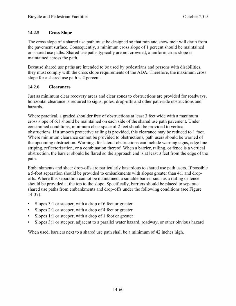
Bicycle and Pedestrian Facilities October 2015
14-60
14.2.5 Cross Slope
The cross slope of a shared use path must be designed so that rain and snow melt will drain from the pavement surface. Consequently, a minimum cross slope of 1 percent should be maintained on shared use paths. Shared use paths typically are not crowned; a uniform cross slope is maintained across the path.
Because shared use paths are intended to be used by pedestrians and persons with disabilities, they must comply with the cross slope requirements of the ADA. Therefore, the maximum cross slope for a shared use path is 2 percent.
14.2.6 Clearances
Just as minimum clear recovery areas and clear zones to obstructions are provided for roadways, horizontal clearance is required to signs, poles, drop-offs and other path-side obstructions and hazards.
Where practical, a graded shoulder free of obstructions at least 3 feet wide with a maximum cross slope of 6:1 should be maintained on each side of the shared use path pavement. Under constrained conditions, minimum clear space of 2 feet should be provided to vertical obstructions. If a smooth protective railing is provided, this clearance may be reduced to 1 foot. Where minimum clearance cannot be provided to obstructions, path users should be warned of the upcoming obstruction. Warnings for lateral obstructions can include warning signs, edge line striping, reflectorization, or a combination thereof. When a barrier, railing, or fence is a vertical obstruction, the barrier should be flared so the approach end is at least 3 feet from the edge of the path.
Embankments and sheer drop-offs are particularly hazardous to shared use path users. If possible a 5-foot separation should be provided to embankments with slopes greater than 4:1 and drop-offs. Where this separation cannot be maintained, a suitable barrier such as a railing or fence should be provided at the top to the slope. Specifically, barriers should be placed to separate shared use paths from embankments and drop-offs under the following conditions (see Figure 14-37):
• Slopes 3:1 or steeper, with a drop of 6 feet or greater • Slopes 2:1 or steeper, with a drop of 4 feet or greater • Slopes 1:1 or steeper, with a drop of 1 foot or greater • Slopes 3:1 or steeper, adjacent to a parallel water hazard, roadway, or other obvious hazard
When used, barriers next to a shared use path shall be a minimum of 42 inches high.
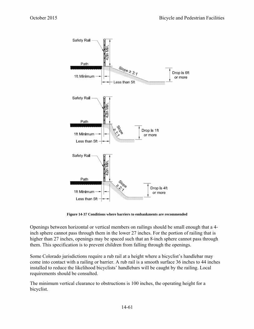
October 2015 Bicycle and Pedestrian Facilities
14-61
Openings between horizontal or vertical members on railings should be small enough that a 4‐inch sphere cannot pass through them in the lower 27 inches. For the portion of railing that is higher than 27 inches, openings may be spaced such that an 8‐inch sphere cannot pass through them. This specification is to prevent children from falling through the openings.
Some Colorado jurisdictions require a rub rail at a height where a bicyclist’s handlebar may come into contact with a railing or barrier. A rub rail is a smooth surface 36 inches to 44 inches installed to reduce the likelihood bicyclists’ handlebars will be caught by the railing. Local requirements should be consulted.
The minimum vertical clearance to obstructions is 100 inches, the operating height for a bicyclist.
Figure 14-37 Conditions where barriers to embankments are recommended
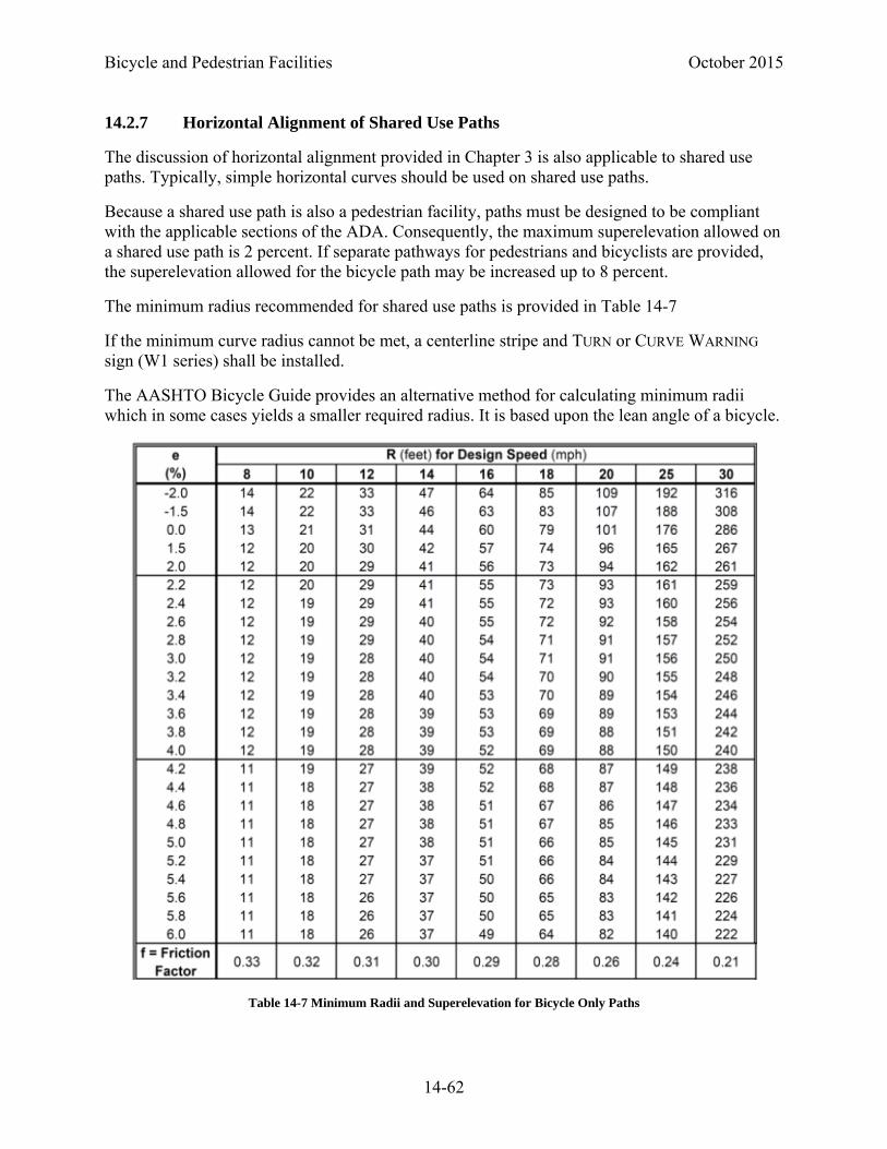
Bicycle and Pedestrian Facilities October 2015
14-62
14.2.7 Horizontal Alignment of Shared Use Paths
The discussion of horizontal alignment provided in Chapter 3 is also applicable to shared use paths. Typically, simple horizontal curves should be used on shared use paths.
Because a shared use path is also a pedestrian facility, paths must be designed to be compliant with the applicable sections of the ADA. Consequently, the maximum superelevation allowed on a shared use path is 2 percent. If separate pathways for pedestrians and bicyclists are provided, the superelevation allowed for the bicycle path may be increased up to 8 percent.
The minimum radius recommended for shared use paths is provided in Table 14-7
If the minimum curve radius cannot be met, a centerline stripe and TURN or CURVE WARNING sign (W1 series) shall be installed.
The AASHTO Bicycle Guide provides an alternative method for calculating minimum radii which in some cases yields a smaller required radius. It is based upon the lean angle of a bicycle.
Table 14-7 Minimum Radii and Superelevation for Bicycle Only Paths
October 2015 Bicycle and Pedestrian Facilities
14-63
14.2.8 Vertical Alignment of Shared Use Paths
Where technically feasible, the maximum continuous grade on a shared use path should be limited to 5 percent. Where right-of-way and geometric constraints make the provision of a continuous grade less than 5 percent impractical, grades should be minimized.
Where potential grades exceed 5 percent, intermittent level resting intervals should be considered. Where provided, resting intervals shall be full width of the shared use path and 60 inches long. Alternatively, a 36-inch wide resting interval may be located adjacent to the shared use path. Recommended maximum distance between resting areas is 200 feet.
Shared use paths located along roadways may follow the grade of the road. Where grades exceed 5 percent, resting intervals should be provided.
Where sustained grades exceeding 4 percent in excess of 300 feet in length are required, an increased design speed should be used. Additionally, consider providing the following mitigating measures:
HILL WARNING signs (W7-5) (Figure 14-38);
Wider clear recovery areas adjacent to the shared use path; and
An additional 6 feet of width to allow some users to dismount and walk their bicycles.
Alternatively, consider installing a series of switchbacks to reduce the longitudinal grade.
Except for ramps on structures, transitions between grades with more than 2 percent algebraic difference should be made with vertical curves. The minimum length for a vertical curve on a shared use path is 3 feet.
On unpaved shared use paths, grades greater than 3 percent are not recommended. Grades exceeding 3 percent can create maintenance (erosion) problems and cause bicycle handling problems for some cyclists.
Figure 14-38 Bicycle HILL WARNING Sign

Bicycle and Pedestrian Facilities October 2015
14-64
In flat terrain, the grade of the shared use path may be controlled by drainage considerations.
14.2.9 Intersections with Shared Use Paths
The background information provided in Chapter 9 of this Roadway Design Guide is applicable to intersections of shared use paths with roadways or other shared use paths.
The fundamental design of intersections requires that users be able to
Perceive the intersection and the potential conflicts
Understand their obligations to yield
Fulfill the obligation to yield
The design criteria in this section and its subsections are intended to support these three fundamental concepts.
When designing shared use path intersections, the sight distance criteria provided in Section 14.2.3.4 and Chapter 9 of this Roadway Design Guide are applicable. Only the design speeds of the intersecting approach legs - using the bicycle as a design vehicle for pathway approaches - are adjusted when applying these criteria to shared use paths.
At shared use path intersections with roadways or with other shared use paths, one facility should be given priority over the other. Four-way stop control should not be used at intersections of shared use paths.
According to the MUTCD (36),
When placement of STOP or YIELD signs is considered, priority at a shared use path/roadway intersection should be assigned with consideration of the following:
A. Relative speeds of shared use path and roadway users;
B. Relative volumes of shared use path and roadway traffic; and
C. Relative importance of shared use path and roadway.
Speed should not be the sole factor used to determine priority, as it is sometimes appropriate to give priority to a high-volume shared-use path crossing a low-volume street, or to a regional shared-use path crossing a minor collector street.
When priority is assigned, the least restrictive control that is appropriate should be placed on the lower priority approaches. STOP signs should not be used where YIELD signs would be acceptable.
The primary consideration in the assignment of traffic control type (STOP as opposed to YIELD signs) at intersections is the availability of adequate sight distance for approaching users. If sight triangles cannot be maintained to provide for yield control, STOP signs must be used. A detailed discussion of sight triangles is provided in Section 14.2.9.1.

October 2015 Bicycle and Pedestrian Facilities
14-65
Where a shared use path crosses a roadway, detectable warnings shall be installed. Where two shared use paths intersect, the approach that is required to yield the right of way should have detectable warnings installed.
Roundabouts can be used at the intersection of two shared use paths. A width of 8 feet should be maintained around the circulating pathway. Splitter islands and central islands on roundabouts for shared use paths should be curbed.
Traffic control for shared use path approaches to intersections is provided in Section 14.2.9.2.
Intersections of shared use paths with roadways should be located outside of the functional area of the intersection of two roadways (Figure 14-39). If a shared use path crosses a roadway within the functional area of an intersection, the path should either be diverted to outside the functional area of the intersection or moved to the intersection and treated as a sidepath crossing (see Section 14.2.13.1).
Traffic signals can be warranted where shared use paths cross roadways, based on any of the nine warrants described in the MUTCD (36). For the School Crossing and Pedestrian Volume warrants all path users may be counted as pedestrians. For the Eight-Hour Vehicular Volume, Four-Hour Vehicular Volume, and Peak Hour warrants only bicycles are counted as vehicles on the path approaches.
Where signals are installed for shared use paths, signal timing shall accommodate the needs of bicyclists and pedestrians.
14.2.9.1 Required Sight Triangles at Shared Use Path Intersections
The decision to use a STOP sign as opposed to a YIELD sign will be primarily determined by the available sight distance required for bicyclists’ at the intersection.
Figure 14-39 Functional Area of an Intersection

Bicycle and Pedestrian Facilities October 2015
14-66
The procedures to determine sight distances at intersections presented in Chapter 9 of the PGDHS) (1) apply to bicycle facilities as well as to roadways. In this section the requirements for each of the following cases is discussed for both stop and yield control:
Case B3 – Stop Controlled crossing maneuver from the minor road
Case C1 – Yield Controlled crossing maneuver from the minor road
For Case B3 where the path is under stop control, the required sight distance at the intersection is a function of the time it takes the slowest design user to cross the street or cross to a refuge island in the middle of a divided roadway. In most cases the slowest design user is the pedestrian. However, since shared use path crossings of roadways are nearly always marked with crosswalks, the sight distance must allow for a motorist to observe and yield to a pedestrian approaching and crossing at the shared use path-roadway intersection. To calculate the required sight triangle, it should be assumed the pedestrian is standing behind the shared use path yield or stop line.
For Case B3 where the road is under stop control, the sight distance should be calculated as provided in the PGDSH (1) using the shared use path design speed as the speed on the major road. By applying equation 9-1 from the PGDSH
1.47
Where
ISD = intersection sight distance (ft)
Vpath = design speed of path (mph)
tg = time gap for minor road vehicle to enter and cross path (sec)
The PGDSH provides a time gap, tg, of 6.5 seconds for passenger cars, 8.5 seconds for single unit trucks, and 10.5 seconds for a combination truck to cross a two-lane roadway based upon observational studies. Consequently, they are conservative for crossing of most shared use paths. However, on multilane roadways where advance STOP or YIELD lines are used, additional time should be allowed: 1.3 seconds additional for a 30-foot advance line and 1.8 seconds for a 50-foot advance line for passenger cars (2.1 seconds and 2.9 seconds for trucks respectively). Additionally, where approach grades exceed 3 percent, add 0.1 second for each percent grade.
The clear sight triangle is that space which should be kept free of obstructions that might block an approaching driver’s view of any potentially conflicting path users. Figure 14-40 illustrates the needed dimensions for calculating the sight triangle for case B3 where motorists are required to stop. Table 14-8 provides the values for those dimensions.

October 2015 Bicycle and Pedestrian Facilities
14-67
Case B3, Motorist Required to Stop
a = assumed distance to driver’s eye
b = intersection sight distance
For Case C3 where the path is under yield control, sight triangles are calculated assuming that the yielding approaches will decelerate to 60 percent of the design speed on the approach to the
Figure 14-40 Illustration of Intersection Sight Triangle Dimensions
Table 14-8 Intersection Sight Distance

Bicycle and Pedestrian Facilities October 2015
14-68
intersection and that the approaches with priority will not decelerate. Sight distances are calculated based upon the time taken for the vehicle on the minor road to cross the intersection. The travel time to reach and clear the major road from the decision point on the minor approach is calculated using the following equations:
0.88
where
1.47
and
tg = time gap for minor road vehicle to reach and clear the major road (sec)
ta = travel time for minor road vehicle to reach the major road while decelerating (sec)
w = width of intersection to be crossed (ft)
La = length of design vehicle (ft)
Vminor = design speed of minor facility (mph)
Vr = reduced speed of minor approach (60 percent design speed)(mph)
am = acceleration rate assumed for minor approach (assume 5 ft/sec/sec)
The length of the sight triangle along the major approach is calculated using the equation
1.47
where
b = sight distance required along major approach (ft)
Vmajor = design speed of major facility (mph)
The sight distance required along the minor approach, a, can be obtained from Table 14-9.
Figure 14-41 illustrates the dimensions for yield control intersections. Users are not shown on the graphic because either approach (major or minor) could be the shared use path.

October 2015 Bicycle and Pedestrian Facilities
14-69
Design Speed of Minor Leg
12 6214 7116 8018 9020 10025 13030 16035 19540 23545 27550 32055 370
Table 14-9 Required Sight Distance for Minor Leg of Yield Control
Where a shared use path approaches a walkway and is required to stop, the legs of the sight triangle should extend 25 feet back from the edge of the sidewalk along the shared use path, and 15 feet back from the edge of the shared use path along the sidewalk (Figure 14-42).
Figure 14-41 Illustration of Intersection Sight Triangle Dimensions. Case C3, Yield Condition

Bicycle and Pedestrian Facilities October 2015
14-70
14.2.9.2 Traffic Control at Intersections with Shared Use Paths
The traffic control provided on shared use paths at intersections with other paths or with roadways is similar to that provided at the intersection of two roadways.
STREET NAME signs (D1-3) should be included for shared use path users.
On the approach to any intersection, a solid yellow centerline should be striped on the approach to the intersection for a distance equal to the stopping sight distance of the shared use path.
An INTERSECTION WARNING (W2 series) or ADVANCE TRAFFIC CONTROL (W3 series) sign may be used on a roadway, street, or shared-use path in advance of an intersection to indicate the presence of an intersection and the possibility of turning or entering traffic. However, these signs are not required unless the engineering judgment determines that the visibility of the intersection is limited on the shared-use path approach to the intersection. When deciding whether to install advance signs, the designer should ensure that intersections and intersection traffic control are visible from at the least stopping sight distance in advance of the intersection. Figure 14-43 shows W2 and W3 series signs.
Figure 14-42 Illustration of Intersection Sight Triangle Dimensions. Path Approaching Sidewalk

October 2015 Bicycle and Pedestrian Facilities
14-71
Where the shared use path user is to yield or stop (with either a STOP sign or a signal) at the intersection, YIELD signs and YIELD lines or STOP signs and STOP lines shall be installed on the path approach to the intersection. YIELD or STOP lines shall be placed 4 feet in advance of the intersecting travel way or sidewalk.
For signal control intersections, detector loops in the pavement and push buttons for pedestrians should be installed on the path approaches.
On the motor vehicle approach, signing and striping will vary depending on which facility is given priority at the intersection. If the path is given priority at the intersection, then the roadway approaches should be signed and marked as they would be on the approach to any intersection with with similar control (YIELD, STOP, or signal control). If the roadway is given priority at the intersection, traffic control appropriate for a midblock crossing must be installed (see Sections 14.3.8 and 14.3.9). At trail crossings, the TRAIL CROSSING (W11-15 and W11-15p) sign assembly (Figure 14-44) should be used instead of the PEDESTRIAN CROSSING sign (W11-2).
At any activated crossing (e.g., a hybrid beacon), if the bicyclists is required to cross the roadway in stages, additional activation mechanisms (i.e., loops, video detection, push buttons) must be placed in the median. Signing should be provided to make bicyclists aware of any requirement on their part to activate multiple crossings.
Figure 14-43 INTERSECTION WARNING (W2 Series) and ADVANCE WARNING SIGNS (W3 Series) Signs
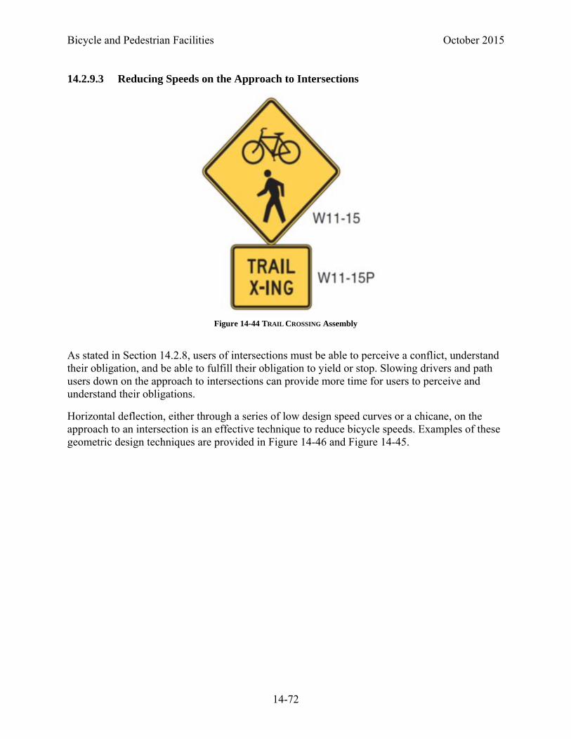
Bicycle and Pedestrian Facilities October 2015
14-72
14.2.9.3 Reducing Speeds on the Approach to Intersections
As stated in Section 14.2.8, users of intersections must be able to perceive a conflict, understand their obligation, and be able to fulfill their obligation to yield or stop. Slowing drivers and path users down on the approach to intersections can provide more time for users to perceive and understand their obligations.
Horizontal deflection, either through a series of low design speed curves or a chicane, on the approach to an intersection is an effective technique to reduce bicycle speeds. Examples of these geometric design techniques are provided in Figure 14-46 and Figure 14-45.
Figure 14-44 TRAIL CROSSING Assembly
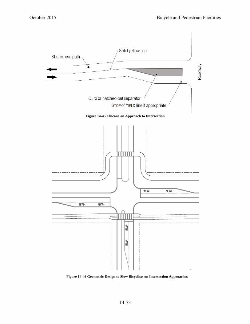
October 2015 Bicycle and Pedestrian Facilities
14-73
Figure 14-45 Chicane on Approach to Intersection
Figure 14-46 Geometric Design to Slow Bicyclists on Intersection Approaches

Bicycle and Pedestrian Facilities October 2015
14-74
14.2.9.4 Curb Ramps
Anytime a shared use path crosses a roadway it is a pedestrian crossing location. ADA compliant curb ramps (if curbs are present) must be installed. The width of the ramp, not inclusive of the flares or curb returns, must be the full width of the approach path. Refer to Section 14.3.1.4 of this chapter.
Detectable warnings must be placed at the base of the curb ramps across the entire width of the ramps or across the entire width of the path on the approach to crossings where no curbs are present.
14.2.9.5 Prevention of Motor Vehicle Encroachment onto Shared Use Paths
On some shared use paths, encroachment by motor vehicles may be a concern. If the primary cause of encroachment is a lack of understanding on the part of motorists of the non-motorized nature of the facility, consider the installation of NO MOTOR VEHICLES (R5-3) (see Figure 14-47) signs at path access points.
Physical barriers to motor vehicles are often ineffective in prohibiting access to motor vehicles. Motorists, and more frequently all-terrain vehicles, often go around or damage objects intended to limit motor vehicle access. Barriers can, however, present obstructions to shared use path users. Consequently, their use should be limited.
One method of discouraging access to motorists is the use of a low, central, dividing island on the path approach to intersections. Combined with tight curb radii, this method can be quite effective. The island should be designed so that emergency and maintenance vehicles can access the path by straddling the island. The width of the path on either side of the island should be at least 6 feet wide; in constrained conditions the path may be narrowed to 5 feet wide on either side of the dividing island. Where divisional islands are provided, solid yellow lines are to be provided in advance of and on either side of the island.
Tight curb radii, such as 2 feet, at path-roadway intersections can reinforce the non-motorized nature of shared use paths. See Figure 14-48.
If bollards are used to restrict motor vehicle access at intersections of roadways with paths, a 6 foot clear space is to be provided between bollards. If more than one bollard is used, then an odd
Figure 14-47 NO MOTOR VEHICLES Sign (R5-3)
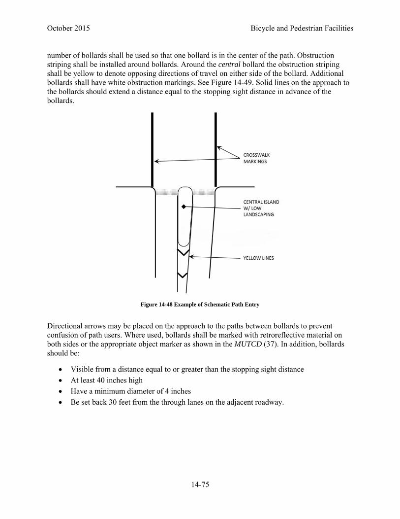
October 2015 Bicycle and Pedestrian Facilities
14-75
number of bollards shall be used so that one bollard is in the center of the path. Obstruction striping shall be installed around bollards. Around the central bollard the obstruction striping shall be yellow to denote opposing directions of travel on either side of the bollard. Additional bollards shall have white obstruction markings. See Figure 14-49. Solid lines on the approach to the bollards should extend a distance equal to the stopping sight distance in advance of the bollards.
Directional arrows may be placed on the approach to the paths between bollards to prevent confusion of path users. Where used, bollards shall be marked with retroreflective material on both sides or the appropriate object marker as shown in the MUTCD (37). In addition, bollards should be:
Visible from a distance equal to or greater than the stopping sight distance
At least 40 inches high
Have a minimum diameter of 4 inches
Be set back 30 feet from the through lanes on the adjacent roadway.
Figure 14-48 Example of Schematic Path Entry
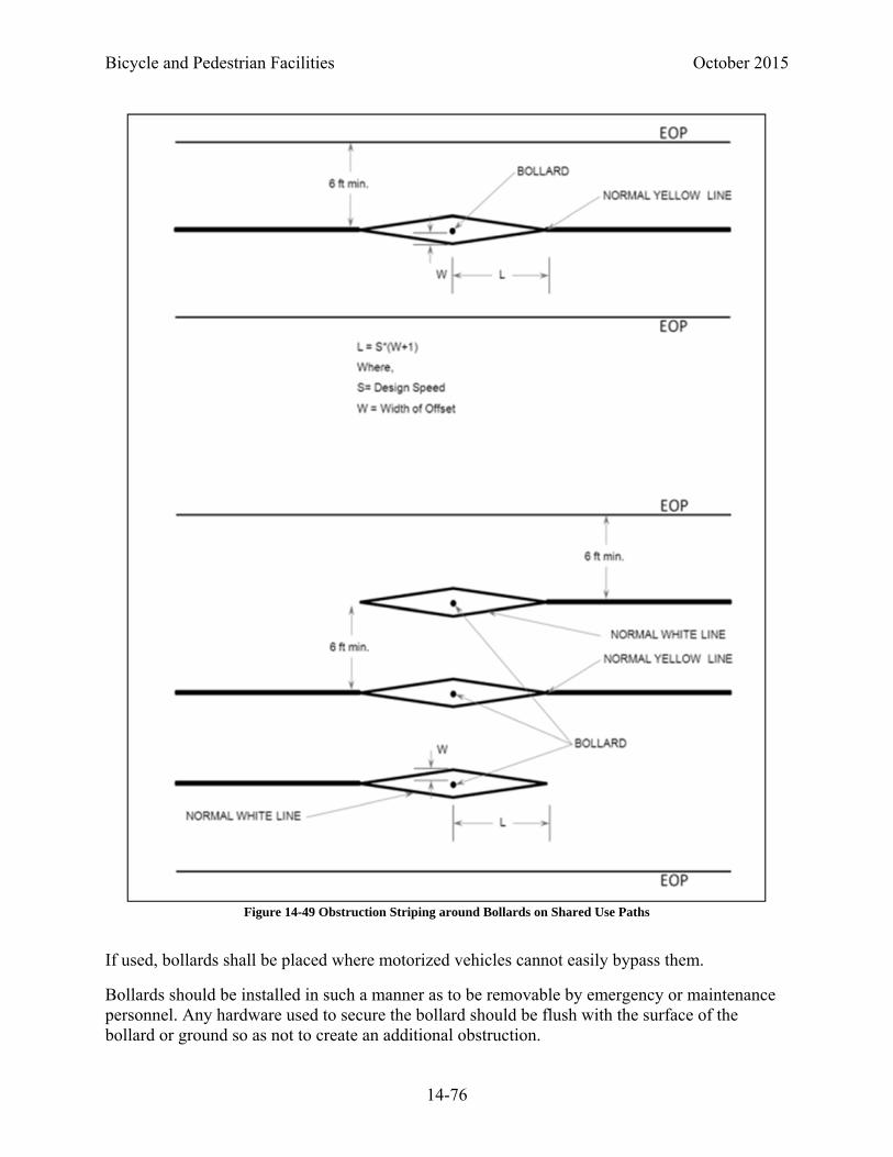
Bicycle and Pedestrian Facilities October 2015
14-76
If used, bollards shall be placed where motorized vehicles cannot easily bypass them.
Bollards should be installed in such a manner as to be removable by emergency or maintenance personnel. Any hardware used to secure the bollard should be flush with the surface of the bollard or ground so as not to create an additional obstruction.
Figure 14-49 Obstruction Striping around Bollards on Shared Use Paths

October 2015 Bicycle and Pedestrian Facilities
14-77
14.2.10 Underpass and Overpass Structures
To maintain the continuity of a shared use path some structures may be required. When a designer has to choose between a tunnel and an overpass the characteristics of each crossing should be considered before determining which structure type is most appropriate. Each structure type has benefits and drawbacks which need to be considered for each individual location. Constraints such as right-of-way, topography, and utility conflicts may dictate whether an overpass or underpass is more appropriate. Overpasses have several benefits. Overpasses generally provide good visibility of surrounding areas which may lead to a greater sense of security, they are well lit during daylight hours, and they more easily accommodate drainage. Conversely, overpasses typically require a greater elevation change and may be more difficult for users to traverse, they are exposed to the elements, and speeds on the downward approaches can be hazardous.
Underpasses often exhibit contrasting characteristics to overpasses. They are protected from the elements and often require less ramping or changes in elevation, typically making them easier to traverse. Underpasses, if not designed properly, can be dark and intimidating and may feel claustrophobic. Underpasses also often present drainage challenges, utility conflicts, and construction phasing issues. Underpasses will often require lighting and additional maintenance such as regular sweeping to remove sedimentation.
Underpass design and layout should consider user safety. Limited visibility through a closed structure may have a negative impact on user’s perception of personal safety. When an underpass is long, wider openings, additional width, or flared ends may be appropriate to improve natural lighting and visibility. Approaches and grades should be evaluated to provide the maximum possible field of vision towards the underpass.
14.2.10.1 Width and Clearance for Structures Serving Shared Use Paths
All bridges and tunnels serving shared used paths should carry the width of the approach path and the minimum clear space of 2 feet on each side of the path across the structure. Carrying the clear space across the structure provides maneuvering space to avoid pedestrians or stopped bicyclists, as well as necessary horizontal shy distance from railing, walls, or barriers.
If the full path width and clear space cannot be carried across a structure, railings with proper end flares should be provided to reduce the path width on approaches (see Section 14.2.6).
Access by emergency or maintenance vehicles should be considered when establishing the clearances of structures serving shared use paths. Motor vehicles authorized to use the path may dictate the vertical and horizontal clearances.
A vertical clearance of 10 feet is desirable for enclosed structures and tunnels. If access for motor vehicles is not required then the minimum vertical clearance provided shall be 8 feet under constrained conditions. Designers may want to consider providing 8.3 feet (100 inches), which is the operating height of a bicyclist, when on a shared use facility (2).

Bicycle and Pedestrian Facilities October 2015
14-78
14.2.10.2 Grades on Structures Serving Shared Use Paths
All structures serving shared use paths must be ADA compliant. Cross slopes shall not exceed 2 percent. If approach grades exceed 5 percent they shall be designed as ramps. Resting intervals measuring 60 inches in the direction of travel along the path and full width of the structure shall be provided a maximum of every 30 inches of rise. See Figure 14-50.
14.2.10.3 Railings on Structures Serving Shared Use Paths
Railings on shared use path structures shall be designed to comply with Section 14.2.6 of this chapter.
14.2.10.4 Railroad Crossings
Where possible, shared use paths should be aligned to cross railroad tracks at near right angles. Where this cannot be accomplished and the crossing angle is less than 45°, SKEWED CROSSING signs (W10-12) shall be placed on the path approaches to the rail crossing.
A railroad-path crossing, like a railroad-highway crossing, involves either a separation of grades or a crossing at-grade. The horizontal and vertical geometrics of a path approaching an at-grade railroad crossing should be constructed in a manner that does not divert a path user’s attention from path surface conditions.
The same types of crossing treatments used for roadway crossings of railroads, ranging from the required CROSSBUCK sign (R15-1) to full signals and gates, can be used on shared use paths.
Figure 14-50 Maximum Spacing of Resting Intervals on Shared Use Path Structure Ramps

October 2015 Bicycle and Pedestrian Facilities
14-79
Where active traffic control devices are not used, a CROSSBUCK ASSEMBLY shall be installed on each approach to a pathway grade crossing. The CROSSBUCK ASSEMBLY may be omitted at station crossings and on the approaches to a pathway grade crossing that are located within 25 feet of the traveled way of a highway-rail or highway-LRT grade crossing. Pathway grade crossing traffic control devices shall be located a minimum of 12 feet from the center of the nearest track.
If used at a pathway grade crossing, an active traffic control system shall include flashing-light beacons for each direction of the pathway. A bell or other audible warning device shall also be provided.
Advance pavement markings and signs shall be used on the approach to railroad crossings. See Figure 14-51. The minimum sizes of pathway grade crossing signs shall be as shown in the shared-use path column in Table 9B-1 of the MUTCD.
If used, swing gates shall be designed to open away from the tracks so that pathway users can quickly push the gate open when moving away from the tracks. If used, swing gates shall be designed to automatically return to the closed position after each use.
To meet the requirements of the draft Public Right of Ways Accessibility Guideline (PROWAG), path surfaces shall be flush with the tops of rails (48). Openings for wheel flanges at path crossings of freight rail track shall be 3 inches maximum. Openings for wheel flanges at path crossings of non-freight rail track shall be 2.5 inches maximum.
Coordinate early and often with the railroads to determine the appropriate design elements.
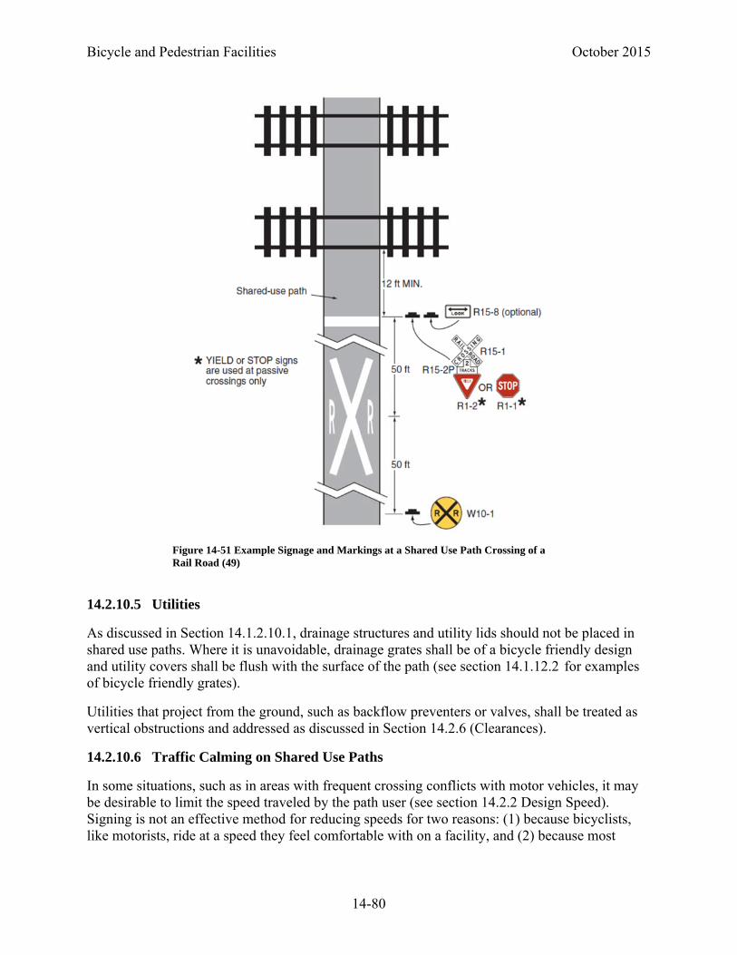
Bicycle and Pedestrian Facilities October 2015
14-80
14.2.10.5 Utilities
As discussed in Section 14.1.2.10.1, drainage structures and utility lids should not be placed in shared use paths. Where it is unavoidable, drainage grates shall be of a bicycle friendly design and utility covers shall be flush with the surface of the path (see section 14.1.12.2 for examples of bicycle friendly grates).
Utilities that project from the ground, such as backflow preventers or valves, shall be treated as vertical obstructions and addressed as discussed in Section 14.2.6 (Clearances).
14.2.10.6 Traffic Calming on Shared Use Paths
In some situations, such as in areas with frequent crossing conflicts with motor vehicles, it may be desirable to limit the speed traveled by the path user (see section 14.2.2 Design Speed). Signing is not an effective method for reducing speeds for two reasons: (1) because bicyclists, like motorists, ride at a speed they feel comfortable with on a facility, and (2) because most
Figure 14-51 Example Signage and Markings at a Shared Use Path Crossing of a Rail Road (49)

October 2015 Bicycle and Pedestrian Facilities
14-81
bicyclists do not have speedometers installed on their bicycle. Consequently, the use of design features is recommended to reduce speeds on shared use paths.
Vertical traffic calming treatments (speed humps, tables or pillows) are not recommended on shared use paths as they can adversely impact the handling of wheeled operators.
Horizontal alignment is the recommended method of reducing speeds on shared use paths. A series of low design speed curves or a chicane along a path, much like those described in Section 14.2.9.4 (Reducing Speeds on the Approach to Intersections), can also be used to reduce speeds at non intersection areas. Advance striping and signage should supplement the trail calming features, either appropriate CURVE WARNING signs or a general text sign indicating that the section of trail is a reduced speed zone.
14.2.11 Wayfinding on Shared Use Paths
The bicycle wayfinding signs described in 14.1.2.1 Bike Routes may be used on shared use paths.
Additional wayfinding signing on shared use paths is often appropriate. On independent alignment paths, information such as the distance between trail heads, or to the next water fountain or restroom facilities are important to path users. Much as Motorists Service signs provide expressway users information on what amenities are available at interchanges, signs may be appropriate to inform path users of the proximity of dining establishments, bike shops, or other destinations of particular interest to path users.
14.2.12 Shared Use Paths Adjacent to the Roadway (Sidepaths)
The term sidepath refers to a shared use path located immediately adjacent and parallel to a roadway.
Ideally, shared use paths will be constructed in their own rights-of-way. However, in some cases a shared use path may be designed adjacent to a roadway. Such cases might include:
Where the public desires a low stress facility to ride on adjacent to a busy or high-speed roadway
As a temporary facility where a roadway cannot be modified to include bike facilities, and
As a connecting facility along a longer shared use path.
It is likely the last condition will be the one that most designers are requested to address. As discussed in Section 14.2.13 the perception of a sidepath as a low stress facility does not necessarily equate to it being a safer facility. For reasons of safety or convenience, a sidepath may not be used by more traffic savvy bicyclists. A sidepath should not be considered a permanent alternative to an in-street facility; rather it should be considered either temporary, or a supplemental facility to serve a specific class of user.
All design criteria associated with shared use paths apply to sidepaths.

Bicycle and Pedestrian Facilities October 2015
14-82
14.2.13 Safety Considerations of Sidepaths
Locating a sidepath immediately adjacent to a roadway can create operation concerns. The AASHTO Bike Guide summarizes many of the problems which may occur in Section 5.2.2. A brief synopsis of the more prevalent concerns are as follows:
Unless separated, they require one direction of bicycle traffic to ride against motor vehicle traffic, contrary to normal rules of the road.
When the path ends, bicyclists going against traffic will tend to continue to travel on the wrong side of the street. Likewise, bicyclists approaching a shared use path often travel on the wrong side of the street in getting to the path. Wrong-way travel by bicyclists is a major cause of bicycle/automobile crashes and should be discouraged at every opportunity.
At intersections, motorists entering or crossing the roadway often will not notice bicyclists approaching from their right, as they are not expecting contra-flow vehicles. Motorists turning to exit the roadway may likewise fail to notice the bicyclist. Even bicyclists coming from the left often go unnoticed, especially when sight distances are limited.
Signs posted for roadway users are backwards for contra-flow bike traffic; therefore these cyclists are unable to read the information without stopping and turning around.
When the available right-of-way is too narrow to accommodate all highway and shared use path features, it may be prudent to consider a reduction of the existing or proposed widths of the various highway (and bikeway) cross-sectional elements (i.e., lane and shoulder widths, etc.). However, any reduction to less than AASHTO Green Book 1 (or other applicable) design criteria must be supported by a documented engineering analysis.
Many bicyclists will use the roadway instead of the shared use path because they have found the roadway to be more convenient, better maintained, or safer. Bicyclists using the roadway may be harassed by some motorists who feel that in all cases bicyclists should be on the adjacent path.
Although the shared use path should be given the same priority through intersections as the parallel highway, motorists falsely expect bicyclists to stop or yield at all cross-streets and driveways. Efforts to require or encourage bicyclists to yield or stop at each cross-street and driveway are inappropriate and frequently ignored by bicyclists.
Stopped cross-street motor vehicle traffic or vehicles exiting side streets or driveways may block the path crossing.
Because of the proximity of motor vehicle traffic to opposing bicycle traffic, barriers are often necessary to keep motor vehicles out of shared use paths and bicyclists out of traffic lanes. These barriers can represent an obstruction to bicyclists and motorists.

October 2015 Bicycle and Pedestrian Facilities
14-83
Additional potential operational and design problems associated with sidepaths include the following:
Because utilities are often located in the right-of-way, it can be difficult to meet clearance and radii requirements within the available space.
In addition to traveling in a direction not expected by motorists exiting driveways or side streets, bicyclists riding on sidepaths are also traveling at speeds significantly greater than those of pedestrians. This makes them less likely to be seen by motorists exiting the side street who may be looking immediately to their right for pedestrians.
If a sidepath is created in a location where there would otherwise be a sidewalk (i.e., a residential neighborhood or an urban commercial district), higher volumes of pedestrians are likely and thus conflicts with pedestrians are likely to increase. While this concern could be mitigated by widening the path, this may increase bicyclists’ speeds in off-peak periods, exacerbating the problem of higher speed cyclists approaching conflict points.
Most roadways have destinations on both sides of the roadway. Since a sidepath serves only one side of the road, this requires sidepath user to cross the roadway midblock to access their destinations or to cross at intersections and ride on a sidewalk (if available) on the opposite side of the road. The former, while not difficult on low volume, low speed streets can be difficult on higher volume, higher speed roadways where sidepaths are likely to be built. The latter may not be legal in some locations.
The proximity of sidepaths to the roadway may result in bicyclists riding at night being subject to glare from approaching car headlamps. This can make it difficult for the bicyclist to see hazards on the trail surface.
Operational problems associated with the visibility of the path user by motorists are most likely to be more significant on higher speed, higher volume, multilane roadways where motorists are focused on the motor vehicle traffic in the travel lanes (20).
14.2.13.1 Potential Mitigation Measures to the Operational Challenges of Sidepaths
Despite the safety, operational, and design challenges with sidepath design, there are times when they are unavoidable. They are often the preferred facility of the public. It may not be possible to improve the roadway to provide an adopted target level of bicycle accommodation. Alternatively, they may be the only way to complete a bicycle network or close a gap in an otherwise continuous facility. Consequently, sidepath design must include measures to help minimize the operational challenges described in Section 14.2.13. The following geometric measures are the ones most likely to improve the operations and safety at sidepath conflict points.
• Divert the sidepath away from the parallel roadway at conflict points. Ideally, the path should be moved far enough away to function as a midblock crossing and be provided with the appropriate traffic control. At a minimum enough space should be provided for one vehicle (25 feet) to queue between the roadway intersection and the crossing sidepath.
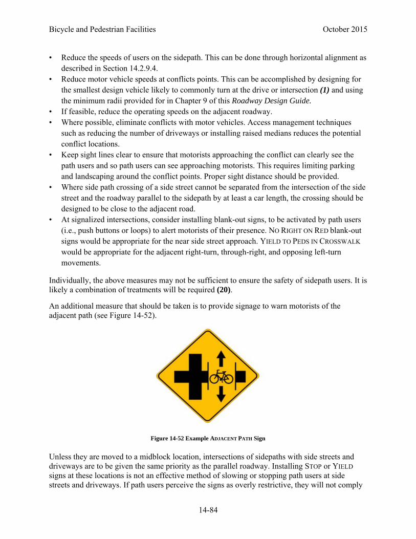
Bicycle and Pedestrian Facilities October 2015
14-84
• Reduce the speeds of users on the sidepath. This can be done through horizontal alignment as described in Section 14.2.9.4.
• Reduce motor vehicle speeds at conflicts points. This can be accomplished by designing for the smallest design vehicle likely to commonly turn at the drive or intersection (1) and using the minimum radii provided for in Chapter 9 of this Roadway Design Guide.
• If feasible, reduce the operating speeds on the adjacent roadway. • Where possible, eliminate conflicts with motor vehicles. Access management techniques
such as reducing the number of driveways or installing raised medians reduces the potential conflict locations.
• Keep sight lines clear to ensure that motorists approaching the conflict can clearly see the path users and so path users can see approaching motorists. This requires limiting parking and landscaping around the conflict points. Proper sight distance should be provided.
• Where side path crossing of a side street cannot be separated from the intersection of the side street and the roadway parallel to the sidepath by at least a car length, the crossing should be designed to be close to the adjacent road.
• At signalized intersections, consider installing blank-out signs, to be activated by path users (i.e., push buttons or loops) to alert motorists of their presence. NO RIGHT ON RED blank-out signs would be appropriate for the near side street approach. YIELD TO PEDS IN CROSSWALK would be appropriate for the adjacent right-turn, through-right, and opposing left-turn movements.
Individually, the above measures may not be sufficient to ensure the safety of sidepath users. It is likely a combination of treatments will be required (20).
An additional measure that should be taken is to provide signage to warn motorists of the adjacent path (see Figure 14-52).
Unless they are moved to a midblock location, intersections of sidepaths with side streets and driveways are to be given the same priority as the parallel roadway. Installing STOP or YIELD signs at these locations is not an effective method of slowing or stopping path users at side streets and driveways. If path users perceive the signs as overly restrictive, they will not comply
Figure 14-52 Example ADJACENT PATH Sign
October 2015 Bicycle and Pedestrian Facilities
14-85
with them. Furthermore, motorists may yield to path users and wave them through in conflict with the sign priority at the intersection. The overuse of these signs may decrease their effectiveness at locations where compliance with STOP or YIELD signs is critical to the path users’ safety.
14.2.14 Sidepath Clearance to the Adjacent Roadway
The minimum midblock separation between a roadway and sidepath is 5 feet from the back of curb or from the edge of pavement if no curb is present.
If 5 feet of separation cannot be provided, a suitable barrier should be provided. If placed, the barrier should be consistent with the requirements of Section 14.2.6. The location of the barrier shall not impair sight distance at intersections.
On low speed roadways (45 mph or less), it is not necessary for the barrier to be designed to redirect errant motorists toward the roadway unless other conditions require a crashworthy barrier. If the railing cannot be designed so as to not be a hazard to motorists, it shall be protected by a guardrail or barrier wall.
It is not acceptable to mount a railing on top of a guardrail unless it has been appropriately crash tested.
On higher speed roadways, barriers between roadway and sidepaths shall be crashworthy.
At some locations where the pathway is located more than 5 feet from a roadway, a guardrail may be placed between the roadway and the sidepath to protect motorists from an object in the clear zone. When a guardrail is located within 3 feet of the shared use path the back of the guardrail should be considered a vertical obstruction next to the path.
Snow storage should be considered when designing sidepaths. A separation distance of 8 feet is desirable to accommodate snow storage. Where space is limited, overall road cross-section design must consider the likely amount of removed snow, the space needed to store it, and how snow will be managed. When snow is stored in the separation area between the road and shared-use path, at least three-fourths of the path should remain usable. The placement of barrier between the roadway and the shared use path must consider the needs of snow removal and drainage.
14.2.15 Equestrian Facilities
Equestrian facilities may be included on some shared use path projects. Shared bicycle, pedestrian and equestrian use is relatively common across the country. However, care must be taken when designing these facilities to minimize the potential conflicts between equestrians and other users as horses can startle, compromising safety for their riders and other users. Where possible, separate trails or bridle paths, should be provided for equestrian use.
For a complete discussion of equestrian planning and design, the designer should refer to the USDA document Equestrian Design Guidebook for Trails, Trailheads, and Campgrounds (38).

Bicycle and Pedestrian Facilities October 2015
14-86
The criteria contained within this section assumes an equestrian path in the same right-of-way as an adjacent shared use path.
14.2.16 Other Considerations on Bicycle Facilities
14.2.16.1 Shared Use Path Lighting
Where shared use paths are used at night, lighting should be provided at intersections with roadways. If implemented, this lighting should be consistent with requirements for roadway intersections contained in Section 5.0 of the CDOT Lighting Design Guide, or as necessary, the AASHTO Roadway Lighting Design Guide. The CDOT Lighting Design Guide is based upon the AASHTO Guide and the IESNA (Illuminating Engineering Society of North America) recommended practices.
Even where paths are not open at night it may be advisable to light roadway crossings.
In-street bicycle lanes shall be lit to the same level as the adjacent roadway.
14.2.16.2 Maintenance of Traffic
Neither portable nor permanent sign supports should be located on bicycle facilities or areas designated for bicycle traffic. If the bottom of a secondary sign that is mounted below another sign is mounted lower than 7 feet above a pathway, the secondary sign should not project more than 4 inches into the pathway facility (47).
Bicyclists should not be exposed to unprotected excavations, open utility access, overhanging equipment, or other such conditions. Except for short duration and mobile operations, when a highway shoulder is occupied, a SHOULDER WORK sign (W21-5) should be placed in advance of the activity area. When work is performed on a paved shoulder 8 feet or more in width, channelizing devices should be placed on a taper having a length that conforms to the MUTCD requirements of a shoulder taper.
If a designated bicycle route is closed because of the work being done, a signed alternate route should be provided. The MUTCD includes approved DETOUR signs for bicycle facilities (Figure 14-53). Bicyclists should not be directed onto a sidewalk or exclusive pedestrian path.
Figure 14-53 Bicycle Facility DETOUR Signs

October 2015 Bicycle and Pedestrian Facilities
14-87
To maintain the systematic use of the fluorescent yellow-green background for pedestrian, bicycle, and school warning signs in a jurisdiction, the fluorescent yellow-green background for pedestrian, bicycle, and school warning signs may be used in Temporary Traffic Control zones.
14.2.16.3 Integration of Bicycles with Transit
Integration of bicycling with transit can increase the utility and extend the range of both modes. Bicyclists sometimes cite trip length, steep grades, and weather as reasons they do not use bicycling as a mode of transportation. By integrating bicycling and transit services, these barriers (real or perceived) can be overcome.
Bicycle racks on, or bicycle space within, transit vehicles can help integrate bicycling and transit. Providing short and long term bicycle parking (40) is a key aspect in making this integration.
Where a change in level occurs at a transit station, some modifications may be considered to make the station accessible to bicyclists. Retrofitting a bicycle channel onto an existing staircase is one technique to improve bicycle access (Figure 14-54).
Another potential integration of bicycles and transit is use of shared facilities. These are discussed in the following sub-sections.
14.2.16.3.1 Shared Bicycle Facilities with Bus Transit
Shared bicycle facilities with transit can take multiple forms.
Ideally, a bus facility - exclusive busway or bus only lanes - would be constructed with separate bicycle facilities. On an exclusive busway this would entail the provision of a shared use path adjacent the busway (Section 14.2 SHARED USE PATHS). Bicycle lanes can be installed adjacent to, and to the left of, a dedicated bus lane (assuming a right side bus lane).
Alternative facilities can include shared bike-bus lanes. A bike-bus lane can be created by using signing and symbols to allow bicycles to use a designated bus lane (Figure 14-55). A sign similar
Figure 14-54 Bicycle Channel (41)

Bicycle and Pedestrian Facilities October 2015
14-88
to the Mandatory Movement Lane Control sign for a bus lane (R3-5gP) could be used. This sign would state that it is a bike lane as well as a bus lane.
14.2.16.3.2 Shared Bicycle Facilities with Light Rail
Shared use paths adjacent to rail lines have been implemented around the country.
If shared use paths are constructed adjacent to light rail, special consideration must be given to crossings near rail stops. Treatments to slow bicyclists should be installed in advance of these crossings. Shared use paths adjacent to light rail should be located at least 5-feet clear of the dynamic envelope of the Light Rail Transit vehicle. This will result in the shared use path being at least 11-feet clear of the rail line.
Barriers, as described in Section 14.2.6 (Clearances) should be provided between the light rail facility and the path where practical.
14.2.16.4 Innovative Signing and Markings
Numerous design treatments and traffic control devices are being used or tested to determine their effectiveness in promoting bicycling and improving bicycle safety. Several of these are discussed in this section.
The decision to use any of these treatments should be made in cooperation with local jurisdictions to ensure consistent application throughout an area. Additionally, a justification for using the treatment should be included in the project file, including any research or supporting documents justifying the use of the treatment. Use of non-standard treatments will require
Figure 14-55 Shared Bus Buffered Bike Lane
October 2015 Bicycle and Pedestrian Facilities
14-89
approval of the Resident Engineer. The headquarters Bicycle and Pedestrian Coordinator shall be consulted on the use of these treatments to ensure uniform application throughout the state.
14.2.16.4.1 Colored Bike Lanes
This treatment has obtained an Interim Approval from the FHWA for application. The interim approval assumes that the green coloring will supplement bike lane striping and marking either at conflict areas or continuously along a bike lane. Where bike lanes are designated with dotted lines (e.g., at intersections) the green paint may be continuous. Coloring of bike lanes is a supplemental treatment and should be used to emphasize the presence of properly designed bike lanes. For further information see FHWA Interim Approval for Optional Use of Green Colored Pavement for Bike Lanes (IA-14).
FHWA has developed specifications for the color.
14.2.16.4.2 Bike Boxes
A bicycle box is a designated area for bicyclists on the approach to a signalized intersection. They are located between the advance motorist stop line and the crosswalk or intersection. It is intended to provide bicyclists with a visible and safe place to wait in front of stopped motorists during the red signal phase. Designed to be used during the red phase, the box is intended to reduce car-bike conflicts, increase bicyclist visibility and provide bicyclists with a head start when the light turns green. Bike boxes allow bicyclists to group together to clear an intersection quickly, and may minimize impediments to other traffic at the onset of the green indication. Pedestrians may also benefit from reduced vehicle encroachment into the cross walk when bike boxes are present.
At intersections with high numbers of conflicts between right-turning motorists and bicyclists consideration should be given to treatments instead of or in addition to the bicycle box. These treatments may include separating conflicting traffic with a leading or exclusive signal and separating turning traffic from through traffic by providing exclusive turn lanes.
A bicycle box should be formed by placing a stop line for motor vehicles a minimum of 10 feet in advance of the crosswalk or intersection. A minimum of one bicycle symbol marking should be placed in the bicycle box. A NO TURN ON RED sign should be installed wherever a bicycle box is placed in a lane from which turns on red would otherwise be permitted.
One concern about the use of bike boxes is how conflicts are addressed when the bicyclist arrives at the intersection just as the traffic signal is turning green for motorists. The motorists are not likely to be expecting a cyclist to move left from the bike lane at the moment the light turns green. In Europe, where this treatment originates, motorists are given a yellow signal prior to the traffic signal turning green; this would serve as a warning to the approaching bicyclist. Often exclusive bicycle signals are provided for bicyclists when using the bike box treatments.
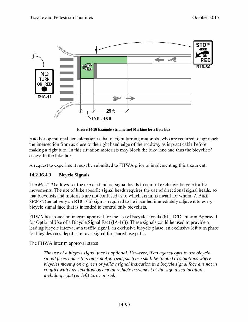
Bicycle and Pedestrian Facilities October 2015
14-90
Another operational consideration is that of right turning motorists, who are required to approach the intersection from as close to the right hand edge of the roadway as is practicable before making a right turn. In this situation motorists may block the bike lane and thus the bicyclists’ access to the bike box.
A request to experiment must be submitted to FHWA prior to implementing this treatment.
14.2.16.4.3 Bicycle Signals
The MUTCD allows for the use of standard signal heads to control exclusive bicycle traffic movements. The use of bike specific signal heads requires the use of directional signal heads, so that bicyclists and motorists are not confused as to which signal is meant for whom. A BIKE
SIGNAL (tentatively an R10-10b) sign is required to be installed immediately adjacent to every bicycle signal face that is intended to control only bicyclists.
FHWA has issued an interim approval for the use of bicycle signals (MUTCD-Interim Approval for Optional Use of a Bicycle Signal Fact (IA-16)). These signals could be used to provide a leading bicycle interval at a traffic signal, an exclusive bicycle phase, an exclusive left turn phase for bicycles on sidepaths, or as a signal for shared use paths.
The FHWA interim approval states
The use of a bicycle signal face is optional. However, if an agency opts to use bicycle signal faces under this Interim Approval, such use shall be limited to situations where bicycles moving on a green or yellow signal indication in a bicycle signal face are not in conflict with any simultaneous motor vehicle movement at the signalized location, including right (or left) turns on red.
Figure 14-56 Example Striping and Marking for a Bike Box
October 2015 Bicycle and Pedestrian Facilities
14-91
The interim approval includes signal design, mounting, and operational requirements. It is available on the internet at http://mutcd.fhwa.dot.gov/res-interim_approvals.htm.
14.2.16.5 Maintenance of Bicycle Facilities
Maintenance of pavement surfaces is critical to safe and comfortable bicycling. While regular maintenance activities will be required, some design treatments will help minimize maintenance needs:
• Place public utilities such as manhole covers and drainage grates outside of bikeways • Ensure that drainage grates, if located on or near a bikeway, have narrow openings and that
the grate openings are placed perpendicular to the riding surface (Figure 14-29) • Design of appropriate cross slopes should help to keep the riding surface clear of debris and
water
14.2.16.5.1 Snow and Ice Control
In designing roadways, roads should be designed to allow for snow storage. The roadside should have adequate space to place plowed snow so that it does not block a shared use path that may be adjacent to the roadway. Separation between road and path allows for snow storage.
14.3 PEDESTRIAN FACILITIES
Pedestrians and their interactions with vehicular traffic are major considerations for highway planning and design (1). Pedestrians are part of every roadway environment and they should be considered in all roadway designs. According to the Policy on the Geometric Design of Streets and Highways (PGDSH):
Because of the demands of vehicular traffic in congested urban areas, it is often very difficult to make adequate provisions for pedestrians. Yet provisions should be made, because pedestrians are the lifeblood of our urban areas, especially the downtown and other retail areas.
Consequently, all design projects on CDOT facilities shall include accommodations for pedestrians.
14.3.1 General Pedestrian Considerations
Pedestrian accommodations can take any of a number of forms. On CDOT projects in urban areas pedestrian accommodations will most often be represented by sidewalks. Separated shared used paths (Section 14.2 -Shared Use Paths) are another class of facility which may be provided for pedestrians. In rural areas, where pedestrian traffic is expected to be light, paved shoulders may accommodate pedestrians.
The degree of pedestrian accommodation provided will be influenced by the land use patterns surrounding the project, or by the planned land use patterns.
Bicycle and Pedestrian Facilities October 2015
14-92
14.3.1.1 Accommodating Pedestrians in the Right-of-Way
The level of accommodation for pedestrians can be measured by a number of methods ranging from subjective to objective.
Often, as part of downtown redevelopment projects or Safe Route to School projects, a walking audit which includes subjective and objective analyses will have been performed. A walking audit documents recommended improvements to the roadway and pedestrian facilities to improve pedestrian accommodation. Any such local plans should be reviewed and the recommendations addressed in the design plans to the maximum extent feasible.
The 2010 Highway Capacity Manual (HCM) (6) establishes an objective method for determining the level of pedestrian accommodation based upon the geometric and operational characteristics of the roadway being analyzed. This method is based upon numerous research projects which quantified what factors influence how pedestrians perceive a roadway and sidewalk safety and comfort. This method is often used by agencies to set minimum target levels of accommodation for pedestrian facilities. The model for links (roadway segments between intersections) includes the following factors:
• Presence and width of a sidewalk • Width of the outside lane • Presence and width of a paved shoulder or bike lane • Presence and width of a parking lane • Percent of parking occupied by parked cars • Presence of trees or a barrier between the sidewalk and the roadway • Operating speeds on the roadway • Traffic volume on the roadway.
The primary geometric conditions that are influenced by design are the presence of a sidewalk, sidewalk width, and the separation of the sidewalk from the outside lane. This HCM methodology is a useful tool for designing cross sectional geometry to meet a target level of pedestrian accommodation.
The Highway Capacity Manual also provides a method for determining the Level of Service based upon sidewalk congestion. This methodology should also be employed also to ensure adequate sidewalk width where high volumes of pedestrians are expected.
As stated above in 14.3.1 General Pedestrian Considerations, on CDOT construction projects, it is likely that sidewalks will be the facility of choice for accommodating pedestrians. However, in some cases, particularly in rural areas where traffic volumes are low and pedestrian traffic is expected to be only occasional, a paved shoulder, may be the only accommodation needed for pedestrians.
When sidewalks are included in projects, they should be continued to logical termini. For example, if a roadway project ends just prior to an intersection, pedestrian improvements should continue to the intersection.
October 2015 Bicycle and Pedestrian Facilities
14-93
14.3.1.2 Operating Characteristics of Pedestrians
There is no single type of design pedestrian. Pedestrians come in all sizes, and with varying degrees of physical and cognitive abilities. It is important to recognize the diversity and wide spectrum of pedestrians’ abilities during facilities design.
Typical pedestrian walking speeds range from approximately 2.5 feet per second to 6.0 feet per second. The MUTCD states that a speed of 3.5 feet per second should be used for calculating pedestrian clearance intervals at pedestrian signals (44). Such seasonal factors as ice and snow can reduce travel speeds below normal.
The space taken up by a single stationary person can be approximated by an ellipse 1.5 feet x 2 feet, with a total area of 3 square feet. In evaluating a pedestrian facility, the HCM assumes an area of 8 square feet including a buffer zone for each pedestrian (45). Two pedestrians walking side by side require at least 4.7 feet of width. Two people in wheelchairs passing each other will need at least 5 feet of width, and if each has an assistive animal, 8 feet of width will be required.
According to the AASHTO Guide for the Planning, Design, and Operation of Pedestrian Facilities (3),
In 1994, an estimated 7.4 million persons in the United States used assistive technology devices for mobility impairments, 4.6 million for orthopedic impairments, 4.5 million for hearing impairments, and 0.5 million for vision impairments. These numbers are expected to increase because there is a positive correlation between an increase in age and an increase in the prevalence rate of device usage. For example, persons who are 65 years and over use mobility, hearing, and vision assistive devices at a rate four times greater than the total population (46).
These pedestrians must be considered in the design of pedestrian facilities.
14.3.1.3 Americans with Disabilities Act Requirements
The Americans with Disabilities Act (ADA) mandates the accommodation of persons with disabilities in pedestrian facility design through the provision of pedestrian access routes.
A pedestrian access route is a continuous and unobstructed walkway within a pedestrian circulation path that provides accessibility.
The standards for accessible routes are set by the U.S. Access Board in the Americans with Disabilities Act Architectural Guidelines for Buildings and Facilities (ADAAG) (47). The ADA standards for public rights-of-way, the Public Rights-of-Way Accessibility Guidelines (PROWAG) are currently in draft form (48). The criteria contained within this Roadway Design Guide will comply with the draft PROWAG; notations will be made when these vary from the ADAAG (47).
All newly designed and newly constructed pedestrian facilities located in the public right-of-way shall comply with these requirements. All altered portions of existing transportation facilities

Bicycle and Pedestrian Facilities October 2015
14-94
located in the public right-of-way shall comply with these requirements to the maximum extent feasible.
If it is technically infeasible to comply with the requirements of the ADA, documentation shall be made to the file to fully justify any non-compliant features of a design. It is not anticipated that right-of-way will be purchased for the sole purpose of complying with the ADA.
14.3.1.4 Curb Ramps and Blended Transitions
Curb ramps shall be installed where a pedestrian access route crosses a raised curb that vertically separates pedestrians from vehicles. Where sidewalks are not separated from the roadway with curb, such as on roadways with open shoulders, the at-grade connection between the sidewalk and roadway is referred to as a blended transition.
Curb ramps shall have a maximum longitudinal slope of 8.33 percent, except that the maximum required length of a curb ramp is 15 feet.
The maximum cross slope of a curb ramp is 2 percent.
A landing a minimum of 4.0 feet by 4.0 feet shall be provided at the top of the ramp run and shall be permitted to overlap other landings and clear floor or ground space. Running slope and cross slopes of landings at intersections shall be 2 percent maximum. Running and cross slope at midblock crossings shall be permitted to meet street or highway grade.
Flared sides with a slope of 10 percent maximum, measured parallel to the curb line, shall be provided where a pedestrian circulation path crosses the curb ramp. Where a curb ramp does not occupy the entire width of a sidewalk, drop-offs at diverging segments shall be protected.
The clear width of landings, blended transitions, and curb ramps, excluding flares, shall be a minimum of 4.0 feet.
Detectable warning surfaces complying with the ADAAG shall be provided where a curb ramp, landing, or blended transition connects to a street (47).
Grade breaks at the top and bottom of curb ramps shall be perpendicular to the direction of the ramp run. At least one end of the bottom grade break shall be at the back of curb. Surface slopes that meet at grade breaks shall be flush.
The counter slope of the gutter or street at the foot of a curb ramp, landing, or blended transition shall be 5 percent maximum.
On a diagonal ramp, where the pedestrian is required to change direction upon entering the crosswalk, a clear space of at least 4.0 feet by 4.0 feet minimum beyond the crosswalk shall be provided within the width of the crosswalk and wholly outside the parallel vehicle travel lane.
14.3.1.5 Vertical Changes in Grade
The maximum instantaneous elevation change on a pedestrian access route without a treatment is one-quarter inch. Changes in level from one quarter to one half inch shall be beveled at a slope

October 2015 Bicycle and Pedestrian Facilities
14-95
of no greater than 2:1. Changes in elevation greater than one half inch shall be designed with a maximum slope of 5 percent.
14.3.2 Sidewalks
Sidewalks shall be provided on all projects on CDOT facilities on which the design year land use is urban. Sidewalks should be provided on both sides of CDOT roadways on these projects.
Sidewalk surfaces shall be firm, stable, and slip resistant. Concrete sidewalks shall have a broom finish to increase skid resistance.
The pedestrian access route along a sidewalk should be designed to maximize straight through movements by pedestrians without the need to divert around utilities, street furniture, or driveways.
Adopted pedestrian plans shall be consulted to determine if a project roadway has been identified for the inclusion of pedestrian facilities. CDOT projects should implement relevant pedestrian plan facility recommendations to the maximum extent possible.
Sidewalks should also be provided on those projects where other factors indicate a need.
14.3.2.1 Separation from Roadway
The separation of a sidewalk from a roadway is an important factor in the perceived safety and comfort of a pedestrian facility (6). The greater the separation from the roadway the more pleasant the facility and consequently the more likely it is to be used by pedestrians.
Separation from the roadway provides benefits beyond the perceived safety and comfort of the pedestrian. Safety is improved by increasing separation from the roadway, particularly on roadways without curb and gutter. A buffer area provides a place to construct curb ramps and driveways outside of the sidewalk area, making it easier to comply with ADA. Buffer areas can also be used for snow storage. Utility poles, parking meters, and signs can be placed in a sufficiently wide buffer, thus ensuring the complete sidewalk width is available for pedestrians.
14.3.2.1.1 Separation from Roadway with Curb and Gutter
If a project roadway is included in an adopted pedestrian plan, the provided separation should comply with target values presented in the plan. Target values may be in the form of adopted minimum separations distances (or buffer, See Figure 14-57) or in target Level of Service values. For minimum level of service values, the separation will need to be calculated based upon roadway and traffic characteristics.
The minimum setback of a sidewalk from the back of curb to accommodate the construction of a perpendicular curb ramp outside of the sidewalk is 7.9 feet. Where possible this separation should be provided between the back of curb and sidewalk on curb and gutter projects.
The minimum width of setback to a sidewalk on an arterial roadway with curb and gutter is 6 feet. Under constrained conditions, this may be reduced to 5 feet. The minimum width of setback

Bicycle and Pedestrian Facilities October 2015
14-96
to a sidewalk on a local or collector roadway with curb and gutter is 4 feet. Under constrained conditions, this may be reduced to 2 feet.
Minimum separation to the sidewalk may be dictated by requirements for snow storage. Regional snow storage requirements should be considered when determining the minimum setback.
Where local jurisdictions are required to maintain the buffer and sidewalk area, maintenance agreements should be obtained during pre-construction.
14.3.2.1.2 Separation from Roadway without Curb and Gutter
If a project roadway is included in an adopted pedestrian plan, the provided separation should comply with target values presented in the plan.
Sidewalks on roadways without curb and gutter should be placed as far from the roadway as practical in the following sequence of desirability (50):
1. As near the right-of-way line as possible
2. Outside of the clear zone
3. Five feet from the shoulder point
4. As far from edge of traffic lane as practical
14.3.2.2 Sidewalk Width
The minimum width for sidewalks on CDOT projects is 5 feet exclusive of the width of the curb.
Under constrained conditions the minimum width may be reduced to 4 feet exclusive of the width of the curb. This is the minimum pedestrian access route width allowed by the draft PROWAG (48). The ADAAG allows for a minimum accessible route of 3 feet in width (47). Where less than 5 feet continuous width is provided, passing spaces shall be provided at intervals of 200 feet maximum. Passing spaces shall be a minimum of 5 feet wide for a distance of 5 feet along the sidewalk.
14.3.2.3 Protruding Objects
Protruding objects, including pedestrian amenities such as street furniture, water fountains, and informational kiosks, shall not reduce the width of the sidewalk to less than 4 feet.
Objects with leading edges more than 27 inches and not more than 80 inches above the sidewalk shall not protrude more than 4 inches into the clear pedestrian path (see Figure 14-57). Objects protruding more than 4 inches into the pedestrian path at more than 27 inches above the sidewalk may not be detectable by cane. Maintaining at least 80 inches clear to overhangs provides clear space to walk under protrusions for most pedestrians.
Objects mounted on free-standing posts or pylons, 27 inches minimum and 80 inches maximum above the sidewalk, shall not overhang into the clear pedestrian path more than 4 inches beyond the post or pylon base measured 6 inches above the sidewalk. Where a sign or other obstruction
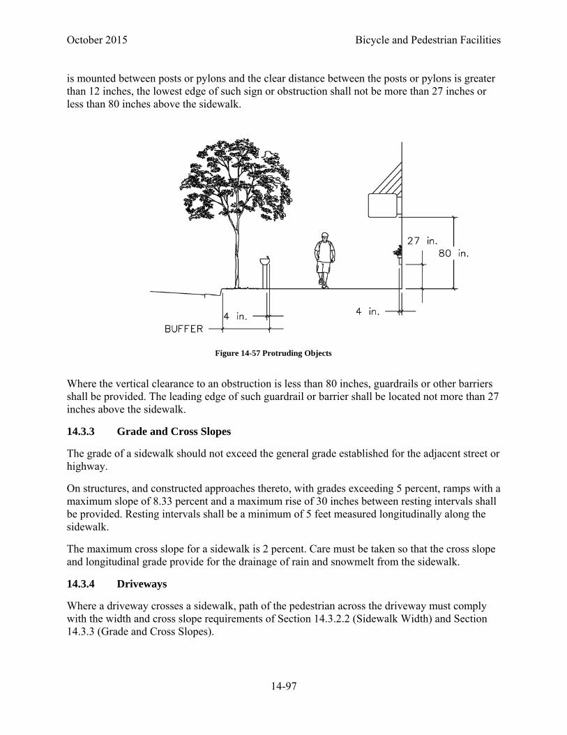
October 2015 Bicycle and Pedestrian Facilities
14-97
is mounted between posts or pylons and the clear distance between the posts or pylons is greater than 12 inches, the lowest edge of such sign or obstruction shall not be more than 27 inches or less than 80 inches above the sidewalk.
Where the vertical clearance to an obstruction is less than 80 inches, guardrails or other barriers shall be provided. The leading edge of such guardrail or barrier shall be located not more than 27 inches above the sidewalk.
14.3.3 Grade and Cross Slopes
The grade of a sidewalk should not exceed the general grade established for the adjacent street or highway.
On structures, and constructed approaches thereto, with grades exceeding 5 percent, ramps with a maximum slope of 8.33 percent and a maximum rise of 30 inches between resting intervals shall be provided. Resting intervals shall be a minimum of 5 feet measured longitudinally along the sidewalk.
The maximum cross slope for a sidewalk is 2 percent. Care must be taken so that the cross slope and longitudinal grade provide for the drainage of rain and snowmelt from the sidewalk.
14.3.4 Driveways
Where a driveway crosses a sidewalk, path of the pedestrian across the driveway must comply with the width and cross slope requirements of Section 14.3.2.2 (Sidewalk Width) and Section 14.3.3 (Grade and Cross Slopes).
Figure 14-57 Protruding Objects

Bicycle and Pedestrian Facilities October 2015
14-98
14.3.5 Sidewalk Lighting
Sidewalk alignments must be considered when designing the roadway lighting pattern. Sidewalks along roadways should be lit to the same level as the adjacent roadway. This is important as pedestrians coming from the side of the road to cross must be adequately lit for motorists to see them.
Roadway lighting designed to light just the travel lanes to design levels may not provide adequate illumination for sidewalks. In these cases, supplemental lighting should be provided.
This lighting shall be consistent with requirements for walkways contained in Section 5.11 of the CDOT Lighting Design Guide, or as necessary, the AASHTO Roadway Lighting Design Guide.
14.3.6 Transit Stops
Where possible, transit waiting areas should be located outside of the sidewalk. Transit pads shall be connected to the sidewalk.
Bus stop boarding and alighting areas shall provide a clear length of 8.0 feet minimum, measured perpendicular to the curb or roadway edge, and a clear width of 5.0 feet minimum, measured parallel to the roadway.
14.3.7 Pedestrian Crossings of Roadways
Careful design of roadway crossings is critical to pedestrians’ mobility and safety. Pedestrian crossings should be designed so that they are convenient for users or pedestrians will choose to cross at other locations, outside the protection of a crosswalk.
ADA compliant curb ramps or blended transitions shall be installed wherever a pedestrian access route crosses a roadway.
14.3.8 Pedestrian Crossings at Intersections
Motorists approaching intersections are primarily concerned with conflicts with other motorists. Consequently, it is important to ensure pedestrians waiting at intersections and approaching motorists are clearly visible to each other.
In urban areas, the minimum curb radii allowed for the design vehicle as found in Chapter 9 of this Roadway Design Guide should be used. This will reduce vehicle speeds and pedestrian crossing distances. Curb extensions should be considered to reduce crossing distances at intersections of streets with on-street parking.
14.3.8.1 Pedestrian Crossings at Uncontrolled Approaches to Intersections
Designated pedestrian crossings of uncontrolled approaches to intersections should be designed as midblock crossings. Guidance on these crossings can be found in Section 14.3.9 (Pedestrian Crossings at Midblock Locations).

October 2015 Bicycle and Pedestrian Facilities
14-99
14.3.8.2 Pedestrian Crossings at Stop and Yield Control Intersections
In urbanized areas, marked crosswalks should be provided wherever a sidewalk crosses a street under stop or yield control. STOP or YIELD lines shall be placed a minimum of 4 feet in advance of the crosswalks.
On multilane roadways under yield control, YIELD lines should be placed 30 feet in advance of the near edge of the intersecting roadway. This advance placement is to improve the visibility of crossing pedestrians to motorists.
14.3.8.3 Pedestrian Crossings at Signal Control Intersections
If an intersection under signal control has sidewalks, then marked crosswalks should be provided. In urbanized areas pedestrian signals are recommended at all intersections where sidewalks are provided on the approaches to a signalized intersection. STOP lines shall be placed a minimum of 4 feet in advance of the crosswalks. Consideration may be given to providing advance right turn STOP lines to improve the visibility of pedestrians coming from the motorist’s left.
Pedestrian push buttons shall be accessible to pedestrians via an accessible pedestrian route in compliance with the ADA.
The draft PROWAG requires that whenever pedestrian signals are installed, accessible pedestrian push buttons be installed (48).
At intersections with high volumes of right turning traffic, raised right turn channelization islands should be provided to allow pedestrians to cross the right turning traffic independently of the rest of the intersection. Single right turn channelization islands should be under yield control and have YIELD lines a minimum of 4 feet in advance of the crosswalk. Pedestrian crossings, crosswalks, and W11-2 (PEDESTRIAN CROSSING sign) should be placed on the approach end of the channelization island to maximize visibility to motorists. Space should be provided beyond the crosswalk for a single motor vehicle to store. Pedestrian signal heads for crossing of the through lanes shall be placed on the concrete channelization island.
Painted channelization islands do not provide the pedestrian advantages of raised channelization islands. Signal poles cannot be placed in painted islands. Consequently the pedestrian signal necessarily applies to the entire crossing, not just the through lanes. This precludes the use of yield control on the slip lane and the right turn must be signalized.
At multilane right turn channelization islands, the draft PROWAG requires the use of accessible pedestrian signals across the turn lanes (48). See the MUTCD Section 4.E.
At intersections with high volumes of pedestrians, consideration should be given to restricting the right turn on red movement. NO RIGHT ON RED blank-out signs may be used to restrict right turns only when pedestrians have pushed the pedestrian push button. This minimizes the delay to motorists due to the right turn restriction.

Bicycle and Pedestrian Facilities October 2015
14-100
Additionally, YIELD TO PEDS IN CROSSWALK blank-out signs can be used to remind right-on-green and permissive left-turn movements of their obligation to yield to pedestrians in the crosswalk.
Another method to reduce pedestrian conflicts with turning motorists is through the use of a leading pedestrian interval. Where leading pedestrian intervals are used, Accessible Pedestrian Signals should be considered.
14.3.8.4 Pedestrian Crossings at Roundabouts
Research suggests that properly designed single-lane roundabouts have fewer pedestrian conflicts and crashes than typical signalized intersections (51). To accommodate pedestrians, roundabouts should be designed to reduce speeds of approaching vehicles. Design speeds through single-lane roundabouts of 12 to 22 mph are typical.
Crosswalks at roundabouts shall be placed a minimum of 20 feet back from the circulating roadway. See Figure 14-58.
Figure 14-58 Location of Pedestrian Crossings at Roundabouts (52)
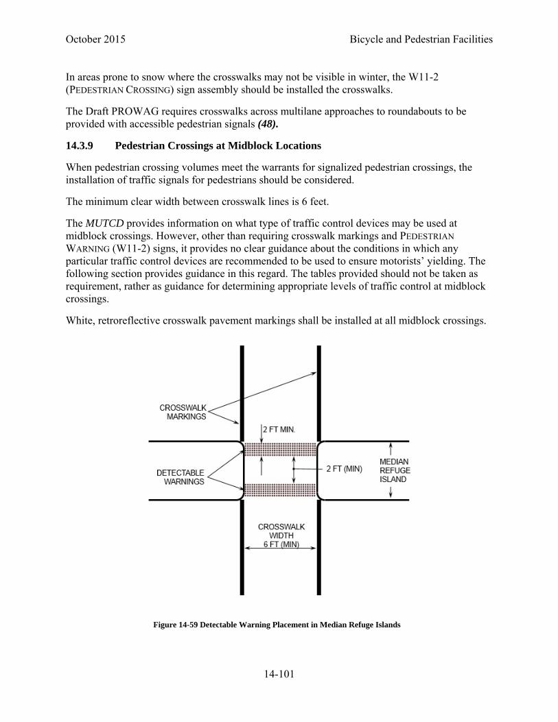
October 2015 Bicycle and Pedestrian Facilities
14-101
In areas prone to snow where the crosswalks may not be visible in winter, the W11-2 (PEDESTRIAN CROSSING) sign assembly should be installed the crosswalks.
The Draft PROWAG requires crosswalks across multilane approaches to roundabouts to be provided with accessible pedestrian signals (48).
14.3.9 Pedestrian Crossings at Midblock Locations
When pedestrian crossing volumes meet the warrants for signalized pedestrian crossings, the installation of traffic signals for pedestrians should be considered.
The minimum clear width between crosswalk lines is 6 feet.
The MUTCD provides information on what type of traffic control devices may be used at midblock crossings. However, other than requiring crosswalk markings and PEDESTRIAN
WARNING (W11-2) signs, it provides no clear guidance about the conditions in which any particular traffic control devices are recommended to be used to ensure motorists’ yielding. The following section provides guidance in this regard. The tables provided should not be taken as requirement, rather as guidance for determining appropriate levels of traffic control at midblock crossings.
White, retroreflective crosswalk pavement markings shall be installed at all midblock crossings.
Figure 14-59 Detectable Warning Placement in Median Refuge Islands
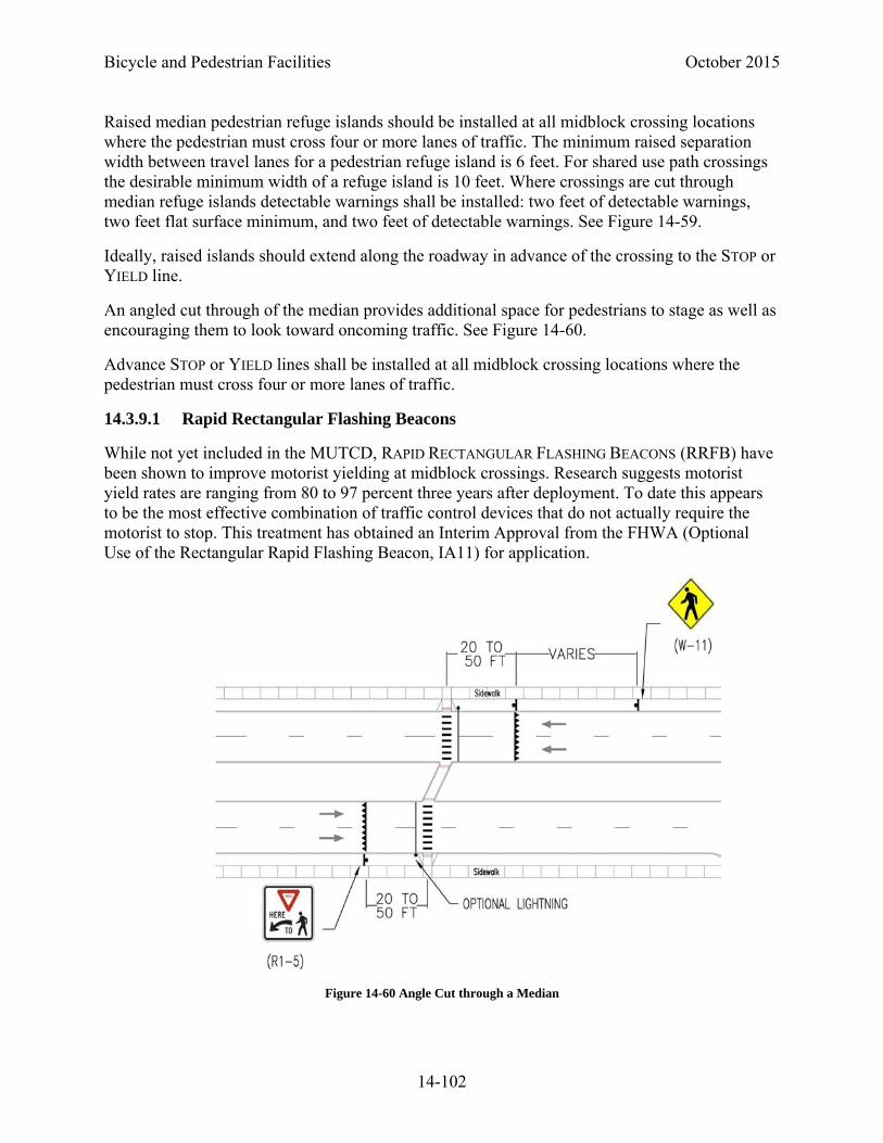
Bicycle and Pedestrian Facilities October 2015
14-102
Raised median pedestrian refuge islands should be installed at all midblock crossing locations where the pedestrian must cross four or more lanes of traffic. The minimum raised separation width between travel lanes for a pedestrian refuge island is 6 feet. For shared use path crossings the desirable minimum width of a refuge island is 10 feet. Where crossings are cut through median refuge islands detectable warnings shall be installed: two feet of detectable warnings, two feet flat surface minimum, and two feet of detectable warnings. See Figure 14-59.
Ideally, raised islands should extend along the roadway in advance of the crossing to the STOP or YIELD line.
An angled cut through of the median provides additional space for pedestrians to stage as well as encouraging them to look toward oncoming traffic. See Figure 14-60.
Advance STOP or YIELD lines shall be installed at all midblock crossing locations where the pedestrian must cross four or more lanes of traffic.
14.3.9.1 Rapid Rectangular Flashing Beacons
While not yet included in the MUTCD, RAPID RECTANGULAR FLASHING BEACONS (RRFB) have been shown to improve motorist yielding at midblock crossings. Research suggests motorist yield rates are ranging from 80 to 97 percent three years after deployment. To date this appears to be the most effective combination of traffic control devices that do not actually require the motorist to stop. This treatment has obtained an Interim Approval from the FHWA (Optional Use of the Rectangular Rapid Flashing Beacon, IA11) for application.
Figure 14-60 Angle Cut through a Median
October 2015 Bicycle and Pedestrian Facilities
14-103
The RRFB treatment is a combination of signing, markings and pedestrian activated strobe and feedback devices. Signing for the RRFB typically includes advance PEDESTRIAN WARNING signs (W11-2) with AHEAD supplemental plaques (W16-9p), and PEDESTRIAN WARNING signs (W11-2) with down arrow supplemental plaques (W16-7p). Pavement markings include yield lines and solid white lane lines (on divided multi-lane roads); the length of these lines is dependent upon the design stopping sight distance for the roadway. The pedestrian activated treatments would be the W11-2 signs with built in rectangular strobe flashers. Additionally, pedestrian visible strobes and a recorded message inform pedestrians when the crossing is activated and instruct them to wait for motorists to yield.
The RRFB should not be used on roadways with more than 4 through lanes. Raised medians should be provided at crossings using the RRFB to provide a space for left hand signs to be installed.
The R1-5 (YIELD HERE TO PED) shall be placed so that it does not restrict motorists’ visibility of the RRFB at the crosswalk.
For the placement of advance stop lines and advance warning signs refer to the MUTCD.
High visibility crosswalks are to be used with the RRFB crossing treatment, as seen in Figure 14-61.
Timing of the flashing beacon should allow for pedestrians to scan for motorists, step from the side of the road and completely cross the street. Depending upon pedestrian volumes, 5 to 10 seconds should be provided for pedestrians to scan for gaps and enter the roadway. For areas with very high pedestrian volumes (more than 10 pedestrians per crossing), additional startup time should be provided. A minimum of 3.5 feet per second crossing speed should be assumed for pedestrians.
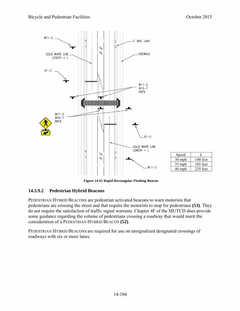
Bicycle and Pedestrian Facilities October 2015
14-104
14.3.9.2 Pedestrian Hybrid Beacons
PEDESTRIAN HYBRID BEACONS are pedestrian activated beacons to warn motorists that pedestrians are crossing the street and that require the motorists to stop for pedestrians (53). They do not require the satisfaction of traffic signal warrants. Chapter 4F of the MUTCD does provide some guidance regarding the volume of pedestrians crossing a roadway that would merit the consideration of a PEDESTRIAN HYBRID BEACON (52).
PEDESTRIAN HYBRID BEACONS are required for use on unsignalized designated crossings of roadways with six or more lanes.
Speed L 30 mph 140 feet 35 mph 185 feet 40 mph 235 feet
Figure 14-61 Rapid Rectangular Flashing Beacon
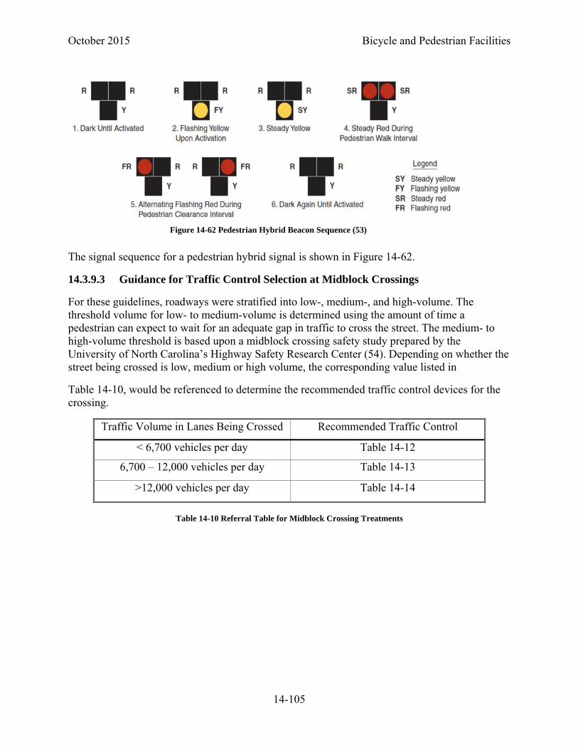
October 2015 Bicycle and Pedestrian Facilities
14-105
The signal sequence for a pedestrian hybrid signal is shown in Figure 14-62.
14.3.9.3 Guidance for Traffic Control Selection at Midblock Crossings
For these guidelines, roadways were stratified into low-, medium-, and high-volume. The threshold volume for low- to medium-volume is determined using the amount of time a pedestrian can expect to wait for an adequate gap in traffic to cross the street. The medium- to high-volume threshold is based upon a midblock crossing safety study prepared by the University of North Carolina’s Highway Safety Research Center (54). Depending on whether the street being crossed is low, medium or high volume, the corresponding value listed in
Table 14-10, would be referenced to determine the recommended traffic control devices for the crossing.
Traffic Volume in Lanes Being Crossed Recommended Traffic Control
< 6,700 vehicles per day Table 14-12
6,700 – 12,000 vehicles per day Table 14-13
>12,000 vehicles per day Table 14-14
Table 14-10 Referral Table for Midblock Crossing Treatments
Figure 14-62 Pedestrian Hybrid Beacon Sequence (53)

Bicycle and Pedestrian Facilities October 2015
14-106
Three tiers of traffic control device packages were identified for these guidelines: static signs, activated signs, and hybrid beacons. The components of each of these packages are provided in Table 14-11 below:
Midblock Crossing Traffic Control Devices TierPreferred Traffic Control Devices
Static Signs
Activated Signs Stop Controlled
Marked Crosswalks
Bicycle or Pedestrian Warning sign with Trail Xing Sign (W11-15) w/ (W11-15P) Or Arrow (W16-7p)2
Advance Yield or Stop Lines5
Trail Xing Sign (advance) and TRAIL XING Pavement Marking
Yield or Stop Here to Ped Signs (R1-5)(R1-5)3,4
RRFB crossing: Ped Xing Signs (W11-2) with rapid rectangular flashing beacons, and solid centerlines on approaches
Pedestrian Hybrid Beacon7
Table 14-11 Traffic Control Devices Tiers
The matrices on the following pages present packages of traffic control devices recommended for specific roadway conditions. While providing guidance, there are sometimes field conditions which make the strict adherence to any typical signing and marking scheme impractical. Therefore, when applied at new locations, each location should be reviewed in the field to ensure the proposed treatments are appropriate.
If sight distance is limited, additional traffic control may be appropriate.
Additional traffic control may be appropriate in areas where expected pedestrians are predominately school children or individuals with mobility impairments.
The following general notes should be considered when using Table 14-12, Table 14-13, and Table 14-14.

October 2015 Bicycle and Pedestrian Facilities
14-107
Table 14-13 Roadway Volume greater than 650 vph1 (6,700 vpd), and less than 1,150 vph (12,000 vpd)
Table 14-14 Roadway Volume greater than 1,1501 vph (12,000 vpd)
Table 14-12 Roadway Volume less than 650 Vehicles per hour, vph (6,700 vehicles per day1, vpd)
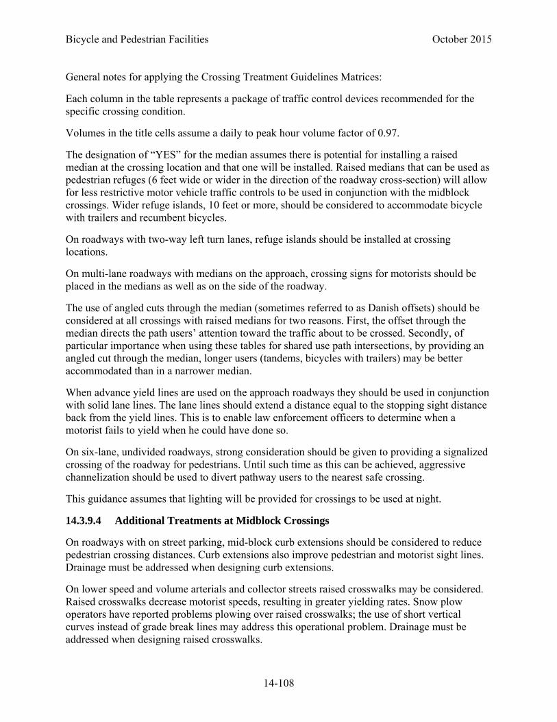
Bicycle and Pedestrian Facilities October 2015
14-108
General notes for applying the Crossing Treatment Guidelines Matrices:
Each column in the table represents a package of traffic control devices recommended for the specific crossing condition.
Volumes in the title cells assume a daily to peak hour volume factor of 0.97.
The designation of “YES” for the median assumes there is potential for installing a raised median at the crossing location and that one will be installed. Raised medians that can be used as pedestrian refuges (6 feet wide or wider in the direction of the roadway cross-section) will allow for less restrictive motor vehicle traffic controls to be used in conjunction with the midblock crossings. Wider refuge islands, 10 feet or more, should be considered to accommodate bicycle with trailers and recumbent bicycles.
On roadways with two-way left turn lanes, refuge islands should be installed at crossing locations.
On multi-lane roadways with medians on the approach, crossing signs for motorists should be placed in the medians as well as on the side of the roadway.
The use of angled cuts through the median (sometimes referred to as Danish offsets) should be considered at all crossings with raised medians for two reasons. First, the offset through the median directs the path users’ attention toward the traffic about to be crossed. Secondly, of particular importance when using these tables for shared use path intersections, by providing an angled cut through the median, longer users (tandems, bicycles with trailers) may be better accommodated than in a narrower median.
When advance yield lines are used on the approach roadways they should be used in conjunction with solid lane lines. The lane lines should extend a distance equal to the stopping sight distance back from the yield lines. This is to enable law enforcement officers to determine when a motorist fails to yield when he could have done so.
On six-lane, undivided roadways, strong consideration should be given to providing a signalized crossing of the roadway for pedestrians. Until such time as this can be achieved, aggressive channelization should be used to divert pathway users to the nearest safe crossing.
This guidance assumes that lighting will be provided for crossings to be used at night.
14.3.9.4 Additional Treatments at Midblock Crossings
On roadways with on street parking, mid-block curb extensions should be considered to reduce pedestrian crossing distances. Curb extensions also improve pedestrian and motorist sight lines. Drainage must be addressed when designing curb extensions.
On lower speed and volume arterials and collector streets raised crosswalks may be considered. Raised crosswalks decrease motorist speeds, resulting in greater yielding rates. Snow plow operators have reported problems plowing over raised crosswalks; the use of short vertical curves instead of grade break lines may address this operational problem. Drainage must be addressed when designing raised crosswalks.

October 2015 Bicycle and Pedestrian Facilities
14-109
The approach slopes for raised crosswalks shall be marked in accordance with the MUTCD required markings for raised pedestrian (54) crossings as shown Figure 14-63.
14.3.9.5 Signalized Pedestrian Crossings
Where signal warrants for pedestrian crossings are met, the installation of traffic signals should be considered. At midblock locations accessible pedestrian signals shall be provided.
Where accessible pedestrian signals are to be installed, they shall comply with all the requirements of the MUTCD.
14.3.9.6 Grade Separated Pedestrian Crossings
In some locations a grade separated crossing will be the only practical method of getting pedestrians across a roadway. Common examples include crossings of expressways and where children must cross major arterials. When appropriately designed, grade separated pedestrian crossings improve the mobility and safety of pedestrians. Attributes of such a pedestrian crossing include the following (3):
The facility must be located where it is needed and will actually be used.
Crossing structures must be built with adequate widths based on perceptions of safety as well as pedestrian volumes.
The design must be accessible for all users.
Barriers and railings must be provided to add an increased sense of safety to the pedestrian.
The facility must be lit to provide an increased level of security to the pedestrian.
Where grade separated crossings are installed, approaches must meet grade criteria provided in Section 14.3.3 Grade and Cross Slopes.
Where the designer has a choice between a tunnel and an overpass, an overpass is often preferable. Overpasses have security advantages. Additionally, lighting is often a requirement for tunnels and may not be necessary for an overpass. Drainage may also be easier to accommodate on overpasses. Underpasses are often more difficult to construct because of utility conflicts or phasing issues. Additionally, pedestrians are more likely to use an overpass than an underpass. However, overpasses have significantly greater vertical clearance requirements, 17 feet 6 inches over the roadway as opposed to 10 feet over the path surface.
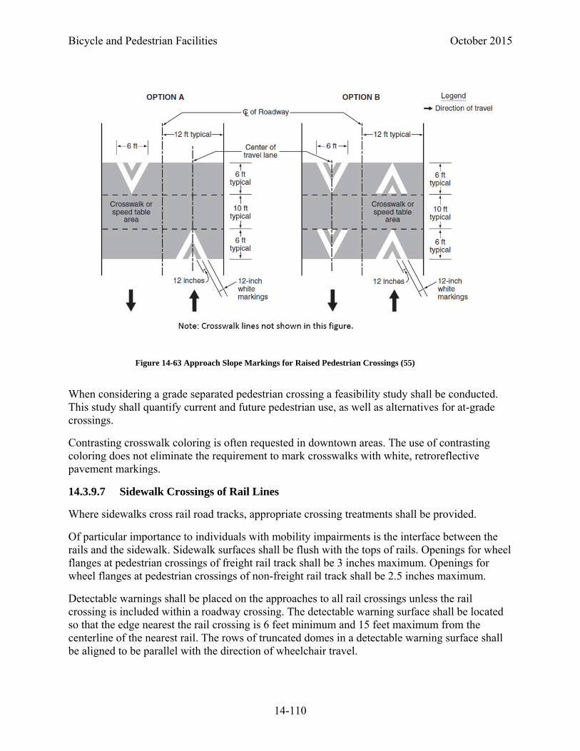
Bicycle and Pedestrian Facilities October 2015
14-110
When considering a grade separated pedestrian crossing a feasibility study shall be conducted. This study shall quantify current and future pedestrian use, as well as alternatives for at-grade crossings.
Contrasting crosswalk coloring is often requested in downtown areas. The use of contrasting coloring does not eliminate the requirement to mark crosswalks with white, retroreflective pavement markings.
14.3.9.7 Sidewalk Crossings of Rail Lines
Where sidewalks cross rail road tracks, appropriate crossing treatments shall be provided.
Of particular importance to individuals with mobility impairments is the interface between the rails and the sidewalk. Sidewalk surfaces shall be flush with the tops of rails. Openings for wheel flanges at pedestrian crossings of freight rail track shall be 3 inches maximum. Openings for wheel flanges at pedestrian crossings of non-freight rail track shall be 2.5 inches maximum.
Detectable warnings shall be placed on the approaches to all rail crossings unless the rail crossing is included within a roadway crossing. The detectable warning surface shall be located so that the edge nearest the rail crossing is 6 feet minimum and 15 feet maximum from the centerline of the nearest rail. The rows of truncated domes in a detectable warning surface shall be aligned to be parallel with the direction of wheelchair travel.
Figure 14-63 Approach Slope Markings for Raised Pedestrian Crossings (55)
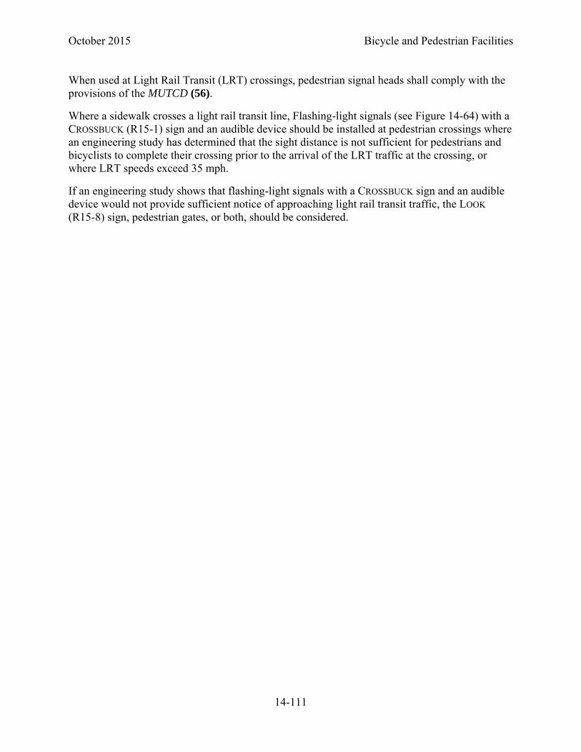
October 2015 Bicycle and Pedestrian Facilities
14-111
When used at Light Rail Transit (LRT) crossings, pedestrian signal heads shall comply with the provisions of the MUTCD (56).
Where a sidewalk crosses a light rail transit line, Flashing-light signals (see Figure 14-64) with a CROSSBUCK (R15-1) sign and an audible device should be installed at pedestrian crossings where an engineering study has determined that the sight distance is not sufficient for pedestrians and bicyclists to complete their crossing prior to the arrival of the LRT traffic at the crossing, or where LRT speeds exceed 35 mph.
If an engineering study shows that flashing-light signals with a CROSSBUCK sign and an audible device would not provide sufficient notice of approaching light rail transit traffic, the LOOK (R15-8) sign, pedestrian gates, or both, should be considered.
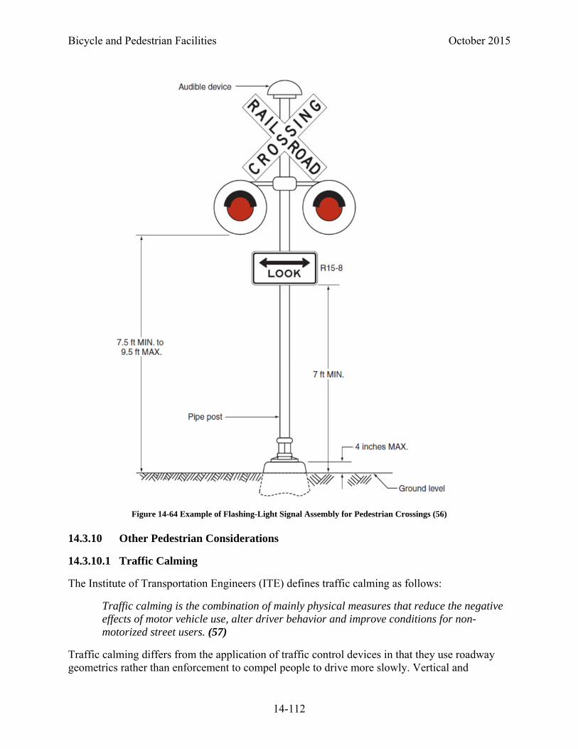
Bicycle and Pedestrian Facilities October 2015
14-112
14.3.10 Other Pedestrian Considerations
14.3.10.1 Traffic Calming
The Institute of Transportation Engineers (ITE) defines traffic calming as follows:
Traffic calming is the combination of mainly physical measures that reduce the negative effects of motor vehicle use, alter driver behavior and improve conditions for non-motorized street users. (57)
Traffic calming differs from the application of traffic control devices in that they use roadway geometrics rather than enforcement to compel people to drive more slowly. Vertical and
Figure 14-64 Example of Flashing-Light Signal Assembly for Pedestrian Crossings (56)

October 2015 Bicycle and Pedestrian Facilities
14-113
horizontal alignment are used to physically restrict the speeds motorists are comfortable driving. Thus, traffic calming is self-enforcing.
Traffic calming is often used in combination with other treatments such as landscaping and lighting. While these additional treatments do not compel drivers to slow down, they may provide a visual signal to drive more slowly.
Traffic calming is popular in many communities because it is effective when applied properly. By reducing speeds, the number of traffic crashes is reduced and those crashes that do occur are often less severe than on uncalmed streets. By reducing speeds, pedestrians’ perceptions of safety and comfort are improved as well.
ITE and FHWA have produced the document Traffic Calming: State of the Practice (58) for informational purposes. While it does not include recommendations on the best course of action or the preferred application of the data, it does provide an excellent resource for those considering the application of traffic calming treatments.
14.3.10.2 Pedestrian Amenities
Pedestrian amenities can provide a more pleasant walking environment and thus encourage more pedestrian activity. Pedestrian amenities can include aesthetic paving treatments, street furniture, shade trees, enhanced lighting, landscaping, informational signing, and public art. Because transit users begin and end their trips as pedestrians, amenities - particularly street furniture and informational signing - can encourage greater transit use. Prior to installing pedestrian amenities, a maintenance agreement should be in place to ensure local jurisdictions the amenities will be maintained.
If aesthetic paving treatments are used they shall be firm, stable, and slip resistant. Cobbles or other treatments that create a vibratory surface for wheelchair users shall not be used within the pedestrian walkway; they may be used in border areas.
Pedestrian amenities shall be designed so that they do not reduce the pedestrian access route to less than 4 feet and shall meet all the criteria of Section 14.3.2.3 Protruding Objects.
Shade trees and landscaping shall be designed so as not to restrict intersection sight distances, or to restrict pedestrian or motorists sight distances at midblock crossings.
14.3.10.3 Pedestrian Wayfinding Signing
Pedestrian wayfinding signing is important to provide information on walk routes to destinations and attractions for pedestrians. Pedestrian wayfinding can encourage pedestrian activity and transit use.
Specific pedestrian routes can be developed. The development of pedestrian routes should include the participation of local agencies and walking interest groups.
The MUTCD does not provide specific signs to be used for pedestrian wayfinding. Local jurisdictions may be consulted concerning the design or visual theme of pedestrian signage.

Bicycle and Pedestrian Facilities October 2015
14-114
However, standard alphabets with a minimum text height of 2 inches shall be used for pedestrian signs to ensure legibility.
14.3.10.4 On-street Parking
The presence of on-street parking significantly impacts the pedestrian environment. On-street parking provides an additional buffer between the travel lanes and the sidewalk; thus, it improves pedestrians’ perceptions of safety and comfort. On-street parking often results in reduced motor vehicle travel speeds, further improving the pedestrian environment. By its very nature, on-street parking encourages pedestrian activity, walking along the road and increasing the number of pedestrians crossing the street.
Where on-street parking exists, curb extensions should be considered to restrict parking near intersections and midblock crossing locations. Drainage patterns will need to be considered during the design of curb extensions.
14.3.11 School Areas
School zones represent a particular challenge to pedestrian design. Children are the most unpredictable, least traffic savvy of pedestrians.
Special consideration should be given to designing pedestrian facilities near schools. Sidewalks should be located as far from the roadway as possible. In some locations, it may be advisable to channelize school children with fences or other barriers; such barriers should be designed so that they do not create sight distance limitations.
If midblock crossings are installed for school crossings, enhanced treatments shall be considered. Roadway volume thresholds for
Table 14-11, Table 14-12, Table 14-13 should be reduced by 20 percent. School children shall not be required to cross more than two lanes without a traffic signal. On roadways with raised pedestrian refuge islands, a four-lane divided roadway is the maximum width crossing without a traffic signal that may be provided specifically for school children.
October 2015 Bicycle and Pedestrian Facilities
14-115
Reduced speed zones may be considered in school zones. When using the SCHOOL SPEED LIMIT
ASSEMBLY, the use of timed flashers is recommended (Figure 14-65). The use of the WHEN
CHILDREN PRESENT (S4-3) plaque is not recommended.
Consideration should be given to restricting right turn on red during periods when students are walking to and from school. Again, use of the WHEN CHILDREN PRESENT (S4-3) plaque is not recommended. Consideration should be given to using designated times for the no right on red or using blank-out signs pre-timed to school walking periods.
Pedestrian staging areas at intersections and midblock crossings should be designed to accommodate the expected volume of students who will be waiting to cross.
Student drop-off and pickup areas should be contained within the school site. If this is not possible and street-side drop-off and pickup is allowed, it shall not require students to make an unsupervised crossing of a roadway.
14.3.12 Maintenance of Traffic (58)
The following section is taken from the MUTCD. It includes the guidance and standard sections form the MUTCD. For support text, see section 6D of the MUTCD.
14.3.12.1 Pedestrian Considerations in Temporary Traffic Control Zones
Advance notification of sidewalk closures shall be provided by the maintaining agency or contractor.
If the temporary traffic control (TTC) zone affects the movement of pedestrians, adequate pedestrian access and walkways shall be provided. If the TTC zone affects an accessible and detectable pedestrian facility, the accessibility and detectability shall be maintained along the alternate pedestrian route.
The following three items should be considered when planning for pedestrians in TTC zones:
Pedestrians should not be led into conflicts with vehicles, equipment, and operations
Figure 14-65 SCHOOL SPEED LIMIT Assembly
Bicycle and Pedestrian Facilities October 2015
14-116
Pedestrians should not be led into conflicts with vehicles moving through or around the worksite
Pedestrians should be provided with a convenient and accessible path that replicates as nearly as practical the most desirable characteristics of the existing sidewalks or footpaths
A pedestrian route should not be severed or moved for non-construction activities such as parking for vehicles and equipment.
To accommodate the needs of pedestrians, including those with disabilities, the following considerations should be addressed when temporary pedestrian pathways in TTC zones are designed or modified:
Provisions for continuity of accessible paths for pedestrians should be incorporated into the TTC plan.
Access to transit stops should be maintained.
A smooth, continuous hard surface should be provided throughout the entire length of the temporary pedestrian facility. There should be no curbs or abrupt changes in grade or terrain that could cause tripping or be a barrier to wheelchair use. The geometry and alignment of the facility should meet the applicable requirements of the “Americans with Disabilities Act Accessibility Guidelines for Buildings and Facilities (ADAAG)” (48).
The width of the existing pedestrian facility should be provided for the temporary facility if practical.
Traffic control devices and other construction materials and features should not intrude into the usable width of the sidewalk, temporary pathway, or other pedestrian facility. When it is not possible to maintain a minimum width of 60 inches throughout the entire length of the pedestrian pathway, a 60 x 60-inch passing space should be provided at least every 200 feet to allow individuals in wheelchairs to pass.
Blocked routes, alternate crossings, and sign and signal information should be communicated to pedestrians with visual disabilities by providing devices such as audible information devices, accessible pedestrian signals, or barriers and channelizing devices that are detectable to the pedestrians traveling with the aid of a long cane or who have low vision. Where pedestrian traffic is detoured to a TTC signal, engineering judgment should be used to determine if pedestrian signals or accessible pedestrian signals should be considered for crossings along an alternate route.
When channelization is used to delineate a pedestrian pathway, a continuous detectable edging should be provided throughout the length of the facility such that pedestrians using a long cane can follow it. These detectable edgings should comply with the provisions of the MUTCD.
Signs and other devices mounted lower than 7 feet above the temporary pedestrian pathway should not project more than 4 inches into accessible pedestrian facilities.
Fencing should not create sight distance restrictions for road users. Fences should not be constructed of materials that would be hazardous if impacted by vehicles. Wooden railing,
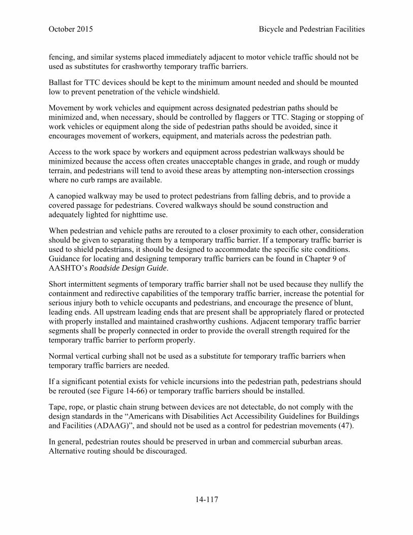
October 2015 Bicycle and Pedestrian Facilities
14-117
fencing, and similar systems placed immediately adjacent to motor vehicle traffic should not be used as substitutes for crashworthy temporary traffic barriers.
Ballast for TTC devices should be kept to the minimum amount needed and should be mounted low to prevent penetration of the vehicle windshield.
Movement by work vehicles and equipment across designated pedestrian paths should be minimized and, when necessary, should be controlled by flaggers or TTC. Staging or stopping of work vehicles or equipment along the side of pedestrian paths should be avoided, since it encourages movement of workers, equipment, and materials across the pedestrian path.
Access to the work space by workers and equipment across pedestrian walkways should be minimized because the access often creates unacceptable changes in grade, and rough or muddy terrain, and pedestrians will tend to avoid these areas by attempting non-intersection crossings where no curb ramps are available.
A canopied walkway may be used to protect pedestrians from falling debris, and to provide a covered passage for pedestrians. Covered walkways should be sound construction and adequately lighted for nighttime use.
When pedestrian and vehicle paths are rerouted to a closer proximity to each other, consideration should be given to separating them by a temporary traffic barrier. If a temporary traffic barrier is used to shield pedestrians, it should be designed to accommodate the specific site conditions. Guidance for locating and designing temporary traffic barriers can be found in Chapter 9 of AASHTO’s Roadside Design Guide.
Short intermittent segments of temporary traffic barrier shall not be used because they nullify the containment and redirective capabilities of the temporary traffic barrier, increase the potential for serious injury both to vehicle occupants and pedestrians, and encourage the presence of blunt, leading ends. All upstream leading ends that are present shall be appropriately flared or protected with properly installed and maintained crashworthy cushions. Adjacent temporary traffic barrier segments shall be properly connected in order to provide the overall strength required for the temporary traffic barrier to perform properly.
Normal vertical curbing shall not be used as a substitute for temporary traffic barriers when temporary traffic barriers are needed.
If a significant potential exists for vehicle incursions into the pedestrian path, pedestrians should be rerouted (see Figure 14-66) or temporary traffic barriers should be installed.
Tape, rope, or plastic chain strung between devices are not detectable, do not comply with the design standards in the “Americans with Disabilities Act Accessibility Guidelines for Buildings and Facilities (ADAAG)”, and should not be used as a control for pedestrian movements (47).
In general, pedestrian routes should be preserved in urban and commercial suburban areas. Alternative routing should be discouraged.

Bicycle and Pedestrian Facilities October 2015
14-118
The highway agency in charge of the TTC zone should regularly inspect the activity area so that effective pedestrian TTC is maintained.
14.3.12.2 Accessibility Considerations
The extent of pedestrian needs should be determined through engineering judgment or by the individual responsible for each TTC zone situation. Adequate provisions should be made for pedestrians with disabilities.
When existing pedestrian facilities are disrupted, closed, or relocated in a TTC zone, the temporary facilities shall be detectable and include accessibility features consistent with the features present in the existing pedestrian facility. Where pedestrians with visual disabilities normally use the closed sidewalk, a barrier that is detectable by a person with a visual disability traveling with the aid of a long cane shall be placed across the full width of the closed sidewalk.
If a pushbutton is used to provide equivalent TTC information to pedestrians with visual disabilities, the pushbutton should be equipped with a locator tone to notify pedestrians with visual disabilities that a special accommodation is available, and to help them locate the pushbutton.
Figure 14-66 Pedestrian Facility DETOUR Sign

October 2015 Bicycle and Pedestrian Facilities
14-119
REFERENCES
1. AASHTO. A Policy on Geometric Design of Highways and Streets, American Association of State Highway and Transportation Officials, Washington, D.C.: 2004.
2. AASHTO. Guide for the Development of Bicycle Facilities, American Association of State Highway and Transportation Officials, Washington, D.C.: 1999.
3. AASHTO. Guide for the Planning, Design, and Operation of Pedestrian Facilities, American Association of State Highway and Transportation Officials, Washington, D.C.: 2004.
4. FHWA. Manual on Uniform Traffic Control Devices (MUTCD), Federal Highway Administration, Washington, D.C.: 2009.
5. Colorado Revised Statutes, Section 42-1-102(10).
6. TRB, Highway Capacity Manual 2010, Transportation Research Board, Washington, D.C.:2010. This cite assumes HCM adoption prior to the adoption of this chapter.
7. Landis, B.W, Petritsch, T.A and Huang, H.F. Characteristics of Emerging Road and Trail Users and Their Safety. Washington, DC: Federal Highway Administration, 2004. FHWA‐HRT‐04‐104.
8. FHWA. MUTCD, Section 9B.21, FHWA. Manual on Uniform Traffic Control Devices, Federal Highway Administration, Washington, D.C.: 2009.
9. FHWA. MUTCD, Section 9B.06, FHWA. Manual on Uniform Traffic Control Devices, Federal Highway Administration, Washington, D.C.: 2009.
10. Colorado Revised Statutes, Section 42-4-1412(5).
11. FDOT, Florida Traffic Engineering Manual, Florida Department of Transportation, Tallahassee, FL: 2010.
12. FHWA. MUTCD, Section 9C.07, FHWA. Manual on Uniform Traffic Control Devices, Federal Highway Administration, Washington, D.C.: 2009.
13. AASHTO. Guide for the Development of Bicycle Facilities, pp. 16, American Association of State Highway and Transportation Officials, Washington, D.C.: 1999.
14. Colorado Revised Statutes, 42-4-901(1)(a).
15. FHWA. MUTCD, Section 3A.06, FHWA. Manual on Uniform Traffic Control Devices, Federal Highway Administration, Washington, D.C.: 2009.
16. Stutts, J.C and Hunter, W.W. Injuries to Pedestrians and Bicyclists: An Analysis Based on Hospital Emergency Department Data. Washington, DC : Federal Highway Administration, 1997. FHWA‐RD‐99‐10 078.

Bicycle and Pedestrian Facilities October 2015
14-120
17. Hunter, W.W, Stutts, J.C, Pein, W.E and Cox, C.L. Pedestrian and Bicycle Crash Types of the Early 1990's. Washington, DC : Federal Highway Administration, 1996. FHWA‐RD‐95‐163.
18. Wachtel and Lewiston. “Risk Factors for Bicycle-Motor Vehicle Collisions at Intersections.” ITE Journal, September, 1994.
19. Moritz, W. “Adult bicyclists in the United States - Characteristics and Riding Experience in 1996.” Transportation Research Record 1636, TRB, National Research Council, Washington, D.C.: 1998
20. Petritsch, Landis, Huang, and Challa. “Sidepath Safety Model - Bicycle Sidepath Design Factors Affecting Crash Rates.” Transportation Research Record 1982, National Research Council, Washington D.C.: 2006
21. Colorado Revised Statutes, Section 42-4-1007(1)(a).
22. FHWA. MUTCD, Section 9C.04, FHWA. Manual on Uniform Traffic Control Devices, Federal Highway Administration, Washington, D.C.: 2015.
23. Colorado Revised Statutes, Section 42-4-1412(8).
24. SRF Consulting Group, Inc., “Bicycle and Pedestrian Transportation” FHWA, Washington, D.C.: 2003.
25. FHWA. MUTCD, Section 9C.05, FHWA. Manual on Uniform Traffic Control Devices, Federal Highway Administration, Washington, D.C.: 2009.
26. FHWA. MUTCD, Section 9B.13, FHWA. Manual on Uniform Traffic Control Devices, Federal Highway Administration, Washington, D.C.: 2009.
27. FHWA. MUTCD, Section 9D.02, FHWA. Manual on Uniform Traffic Control Devices, Federal Highway Administration, Washington, D.C.: 2009.
28. FHWA, Traffic Signal Timing Manual, FHWA ,Washington, D.C.: 2008.
29. FHWA “Accommodating Bicycle and Pedestrian Travel: A Recommended Approach – A US DOT Policy Statement on Integrating Bicycling and Walking into Transportation Infrastructure,” 2000.
30. Colorado Revised Statutes, Section 42-4-204.
31. FHWA. Shared Use Path Level of Service ‐ A User's Guide, FHWA‐HRT‐05‐138, Federal Highway Administration, Washington, D.C.: 2006.
32. FHWA. Shared Use Path Level of Service Calculator, available online at http://www.tfhrc.gov/safety/pedbike/pubs/05138/ , FHWA‐HRT‐05‐138, Federal Highway Administration, Washington, D.C.: 2006.
October 2015 Bicycle and Pedestrian Facilities
14-121
33. FHWA. MUTCD, Section 9B, FHWA. Manual on Uniform Traffic Control Devices, Federal Highway Administration, Washington, D.C.: 2009.
34. Architectural Barriers Act Accessibility Guidelines for Outdoor Developed Areas. United States Access Board, Washington, D.C.: 2007.
35. FHWA. MUTCD, Section 9B.03, FHWA. Manual on Uniform Traffic Control Devices, Federal Highway Administration, Washington, D.C.: 2009.
36. FHWA. MUTCD, Section 4C, FHWA. Manual on Uniform Traffic Control Devices, Federal Highway Administration, Washington, D.C.: 2009.
37. FHWA. MUTCD, Section 9B.26, FHWA. Manual on Uniform Traffic Control Devices, Federal Highway Administration, Washington, D.C.: 2009.
38. USDA, Equestrian Design Guidebook for Trails, Trailheads, and Campgrounds, US Department of Agriculture (in cooperation with FHWA), Washington, D.C.: 2007.
39. FHWA. MUTCD, Section 6, FHWA. Manual on Uniform Traffic Control Devices, Federal Highway Administration, Washington, D.C.: 2009.
40. APBP, Bicycle Parking Guidelines, 2nd Edition, Association of Bicycle and Pedestrian Professionals, Cedarburg, WI: 2010.
41. Adapted from City of Toronto, DRAFT Guidelines for the Design and Management of Bicycle Parking Facilities, City of Toronto: 2008.
42. MN/DOT, MN/DOT Bikeway Facility Design Manual, St. Paul, MN: 2007.
43. Oregon Department of Transportation, Oregon Bicycle and Pedestrian Plan, Salem, OR: 1995.
44. FHWA. MUTCD, Section 4E.06, FHWA. Manual on Uniform Traffic Control Devices, Federal Highway Administration, Washington, D.C.: 2009.
45. TRB, Highway Capacity Manual 2000, Transportation Research Board, Washington, D.C.:20090.
46. U.S. Department of Health and Human Services, Centers for Disease Control and Prevention, National Center for Health Statistics. Trends and Differential Use of Assistive Technology Devices: United States, 1994. Advance Data, No. 292, November 13, 1997.
47. U.S. Access Board, Americans with Disabilities Act Architectural Guidelines for Buildings and Facilities, U.S. Access Board, Washington, D.C:2002. (ADAAG)
48. U.S. Access Board, Revised Draft Guidelines for Accessible Public Rights-of-Way, U.S. Access Board, Washington, D.C.: 2005. (PROWAG)
Bicycle and Pedestrian Facilities October 2015
14-122
49. FHWA. MUTCD, Section 8D.03, FHWA. Manual on Uniform Traffic Control Devices, Federal Highway Administration, Washington, D.C.: 2009.
50. FDOT, Plans Preparation Manual, Florida Department of Transportation, Tallahassee, FL: 2010.
51. FHWA, Roundabouts: An Informational Guide, Report FHWA-RD-00-067, Federal Highway Administration, Washington, D.C.:2000.
52. FHWA. MUTCD, Section 3C.01, FHWA. Manual on Uniform Traffic Control Devices, Federal Highway Administration, Washington, D.C.: 2009.
53. FHWA. MUTCD, Section 4F, FHWA. Manual on Uniform Traffic Control Devices, Federal Highway Administration, Washington, D.C.: 2009.
54. Zegeer, C. V., J. R. Stewart, H. H. Huang, and P. A. Lagerwey. Safety Effects of Marked vs. Unmarked Crosswalks at Uncontrolled Locations, Executive Summary and Recommended Guidelines. Report FHWA-RD-01-075. Federal Highway Administration, U.S. Department of Transportation. Washington, D.C.: 2002.
55. FHWA. MUTCD, Section 3B.26, FHWA. Manual on Uniform Traffic Control Devices, Federal Highway Administration, Washington, D.C.: 2009.
56. FHWA. MUTCD, Section 8C.13, FHWA. Manual on Uniform Traffic Control Devices, Federal Highway Administration, Washington, D.C.: 2009.
57. I.M. Lockwood, “ITE Traffic Calming Definition,” ITE Journal, Vol. 67, July 1997, pp. 22–24.
58. Ewing, Reid H., Traffic Calming: State of the Practice, FHWA-RD-99-135, FHWA and ITE, Washington, D.C.: 1999.
59. FHWA. MUTCD, Section 6D, FHWA. Manual on Uniform Traffic Control Devices, Federal Highway Administration, Washington, D.C.: 2009.
60. FHWA, Separated Bike Lane Planning and Design Guide, FHWA, Washington, D.C.: 2008.
61. National Association of City Transportation Officials. Urban Bikeway Design Guide. Washington, DC, April, 2013, http://nacto.org/wp-content/uploads/2011/03/NACTO_UrbanBikeway_DesignGuide_LRez.pdf
October 2015 Bicycle and Pedestrian Facilities
14-123
INDEX
AASHTO, 8 A Policy on the Geometric Design of
Streets and Highways, 7, 55, 57, 66, 91 Guide for the Development of Bicycle
Facilities, 7, 12, 47, 62 Guide for the Planning, Design, and
Operation of Pedestrian Facilities, 7, 93
Roadside Design Guide, 117 Roadway Lighting Design Guide, 86, 98 U.S. Bicycle Routes, 16
activated flashers, 18, 71, 103 audible device, 111 beacon, 46, 71
pedestrian hybrid, 71, 104, 106 rapid rectangular flashing, 18, 102
bicycle at intersections, 26 boulevard, 46 box, 89 design vehicle, 12 detection, 42 facilities maintenance, 91 key dimensions, 12 key performance criteria, 12 lane, 24, 27, 43
buffered, 39, 40 colored, 89 contraflow, 24 encroachment, 11 markings, 23, 24 roundabout, 45 separated (cycle track), 46 signalization, 43 width, 11, 23, 92
level of service, 11, 23, 57 operating space, 12 routes, 14
general, 15 numbered, 15 U.S. Bicycle Route system, 16
slot, 22
transit, 87 bridge, 18, 49, 77
vertical clearance, 77 width, 77
CDOT Lighting Design Guide, 86, 98 Pavement Design Manual, 49 Policy Directive 1602.0, - Bike and
Pedestrian, 7 Procedural Directive 1602.1, 8
clearance, 60 horizontal, 60, 96 sidepath, 85 vertical, 61, 77, 97
Colorado Bicycle Facilities Map, 10 Context Sensitive Design, 10 cross slope
curb ramp, 94 roadway, 47 shared use path, 60, 78 sidewalk, 97
crossing angle, railroad, 78 crosswalk, 94
high visibility, 103 marked, 99 raised, 108 shared use path, 66
curb ramp, 74, 94, 95, 98 design speed, 12
on grades, 63 shared use path, 50, 81 shared use path intersection, 57, 64, 66,
72 detectable warning, 65, 74, 94, 102, 110 drainage, 47, 80, 91 driveway, 97 equation
activated bicycle warning sign duration, 18
horizontal sightline offset, 52 intersection sight distance, 66, 68 minimum change period, 44

Bicycle and Pedestrian Facilities October 2015
14-124
minimum green time, 44 minimum length of vertical curve, 55 stopping sight distance, 14, 51 stopping sight distance on vertical curves,
55 vertical curve, 14
equestrian facilities, 85 FHWA
bridge design policy, 49 Characteristics of Emerging Road and
Trail Users and Their Safety, 12 Interim Approval for the Optional Use of
Green Colored Pavement, 89 Interim Approval for the Optional Use of
the Rectangular Rapid Flashing Beacon, 102
regarding severing major non-motorized transportation routes, 9
Separated Bike Lane Planning and Design Guide, 39, 46
Traffic Calming State of Practice, with ITE, 113
grade shared use path, 63, 78 sidewalk, 97 unpaved shared use paths, 50 vertical changes, 94 widening shoulders, 22
guardrail, 85 Highway Capacity Manual, 11 horizontal
alignment, 62 curvature, 12 curve
sight distance, 52 stopping sight distance, 52
Illuminating Engineering Society of North America (IESNA) recommended practice, 86
intersection, 82 bicycle boulevard, at, 46 bicycle detection, 42 bicycle left turns, 37 bicycle speed reduction, 72 bike box, 89 bike lanes, 26, 27
buffered bike lanes, 40, 41 continuous flow, 27 contraflow bike lane markings, 25 minimum green time, 43 pedestrian crossing, 98, 99 pedestrian staging areas, 115 pedestrians at signalized, 99 shared use path, 64, 65, 68, 70, 84 sidepath, 84 sight distance, 57, 68 two-stage turn box, 38
lean angle, 62 left turn
bicycles, 37 level of service
bicycle, 11, 23, 57 light rail
shared facilities, 88 lighting
midblock crossing, 108 shared use path, 86 sidewalk, 98
maintenance bicycle facilities, 91
maintenance of traffic, 86, 115 Manual on Uniform Traffic Control
Devices, 7, 8, 101, 111, 116 markings, 39, 42, 103, 109 pedestrian hybrid beacon, 104 setting priority at intersections, 64 signals, 43, 65, 90, 99 signs, 15, 17, 19, 75, 79, 103 temporary traffic control zones, 86, 115 walking speeds, 93
markings advance, 79 bicycle box, 89 bicycle detection symbol, 42 bike lane, 23, 24, 26 buffered bike lane, 39, 40 center line, 25 colored bike lane, 89 contraflow bike lane, 25 crosswalk, 101 obstruction, 48, 75 railroad crossing, 48
October 2015 Bicycle and Pedestrian Facilities
14-125
raised pedestrian crossing, 109 rumble strip warning, 22 SHARED LANE MARKING, 17, 19, 20, 24,
27, 41, 45, 46 STOP line, 38, 66, 71, 99, 102 YIELD line, 66, 71, 99, 102, 103
midblock crossing, 71, 101, 108 lighting, 108 pedestrian staging areas, 115 RAPID RECTANGULAR FLASHING
BEACONS, 102 schools, 114 shared use path, 83 signalized, 109 slope, 94 traffic control, 105, 106, 108
National Association of City Transportaton Officials (NACTO), 40 Urban Bikeway Design Guide, 40, 46
one-way street, 23, 25 operating speed, 11, 92 overpass, 109
vertical clearance, 77 width, 77
parking on-street, 19, 23, 40, 114 parallel, 19
paved shoulders. See shoulder pavement condition, 11 pedestrian crossing
grade separated, 109 Public Rights of Ways Accessibility
Guidelines (PROWAG), 79, 93, 96, 99, 101
radius minimum, 62
railing, 78 railroad, 48, 78
crossing angle, 78 gate, 78 sidewalk crossing, 110 signal, 78
ramp, 63, 78, 97 curb, 74, 94, 95, 98
recovery area, 63
refuge island, 102, 108 retrofit, 20, 27 right turn lane, 26
bicycle, 27 buffered bike lane, 40 requirement to yield, 26 shared lane markings, 41 treatment of shoulders, 22
right turn on red restricting, 115
right-of-way, 18, 26, 49, 63, 65, 82, 83, 86, 92, 94, 96
roundabout, 65, 100 pedestrian crossing, 100
separated bike lane, 46 shared lane, 10 shared use path, 11, 12, 49, 57, 60, 62, 63,
64, 72, 74, 78, 81, 85, 86 equestrian facilities, 85 horizontal alignment, 62 intersection, 64, 65, 70 light rail, 88 lighting, 86 paved, 49 railing, 78 traffic calming, 80 unpaved, 50 vehicle restriction, 74 vertical alignment, 63 wayfinding, 81 width, 57, 65, 74, 77
shoulder additional width, 20, 23 bicycle accommodation, 10, 20 pedestrians, 91 steep grades, 22 width, 82
sidepath, 81 at intersections, 84 operational challenges, 83, 84 safety considerations, 82, 83 separation from roadway, 85 signal, 90
sidewalk, 91, 95 at driveways, 97

Bicycle and Pedestrian Facilities October 2015
14-126
bicycle riding on, 27 lighting, 98 protruding objects, 96 railroad crossing, 110 separation from roadway, 95, 96 width, 92, 93, 96
sight distance, 50, 52, 54, 57, 65 horizontal curve, 52 intersection, 57 vertical curve, 54
sight triangle, 65 signals, 25, 38, 47
actuation, 43 adequate change periods, 43 bicycle, 90 bicycle detection, 38, 42, 43, 71 bike box, 89 bike detection, 71 clearance interval, 44, 93 detection, 46 flashing light, 25 improvement, 19 indication, 44 intersection, 84 minimum green time, 43 pedestrian, 99, 101 pedestrian crossing, 109 railroad, 78 sidepath, 90 supplemental, 44 timing, 43, 46, 65 warning, 60 warrant, 65, 101, 104, 109
signs activated, 106 advance, 79 ADVANCE TRAFFIC CONTROL, 70 BEGIN RIGHT TURN LANE YIELD TO
BIKES, 26 BICYCLE GUIDE, 15 BICYCLE MAY USE FULL LANE, 16, 24 BICYCLE SIGNAL, 44 BICYCLE SIGNAL ACTUATION, 42 bicycle warning, 87 BIKE ROUTE, 15 BIKE SIGNAL, 90
blank-out, 84, 99, 100 CROSSBUCK, 78, 111 crossing, 108 CURVE WARNING, 62, 81 DETOUR, 86 DO NOT ENTER, 25 EXCEPT BICYCLES, 25 HILL WARNING, 63 INTERSECTION WARNING, 70 LOOK, 111 mandatory movement lane control, 88 NO MOTOR VEHICLES, 74 NO RIGHT ON RED, 84, 99 NO TURN ON RED, 38, 89 ONE WAY, 25 PATH USER POSITION, 58 PEDESTRIAN CROSSING, 71, 99, 101 Pedestrian Facility DETOUR, 118 pedestrian warning, 87 PEDESTRIAN WARNING, 101, 103 SCHOOL SPEED LIMIT ASSEMBLY, 115 school warning, 87 SELECTIVE EXCLUSION, 58 SHARE THE ROAD, 17, 20 SHOULDER WORK, 86 SKEWED CROSSING, 48, 78 static, 106 STOP, 47, 64, 65, 71, 84 STREET NAME, 70 TRAIL CROSSING, 71 TURN PROHIBITION, 25 TURN WARNING, 62 U.S. BIKE ROUTE, 16 warning, 87 wayfinding, 46, 81, 113 WHEN CHILDREN PRESENT, 115 YIELD, 64, 65, 71, 84 YIELD HERE TO PED, 103 YIELD TO PEDS IN CROSSWALK, 84, 100
snow, 85, 91, 93, 95, 101 stopping sight distance, 12, 51, 52, 54, 58,
70, 75, 103 horizontal curve, 52 vertical curve, 54
superelevation, 47, 62 temporary traffic control zone, 87, 115, 118

October 2015 Bicycle and Pedestrian Facilities
14-127
traffic calming, 19, 46, 80, 112 shared use path, 80
traffic control, 70 traffic volume, 11, 92 transit, 24, 87, 98, 110
shared facility, 87 stop, 98
tunnel, 18, 49, 77, 109 vertical clearance, 77 width, 77
underpass, 109 vertical clearance, 77 width, 77
United States Code, 9 US DOT Policy Statement, 9 user counts, 10 utilities, 47, 80, 83, 91 vertical alignment, 63
vertical curve length, 12 sight distance, 54 stopping sight distance, 54
wayfinding, 46, 81, 113 bicycle, 14 shared use path, 81
wide curb lane, 10, 19 width
bike lane, 11, 23, 40, 41, 92 buffered bike lane, 39 parking, 92 parking lane, 11 shared use path, 57, 65, 74, 77 shoulder, 11, 20, 22, 82, 92 sidewalk, 92, 93, 96 travel lane, 11, 92