AGi32 - exclusivelycommercial.com · Title: AGi32 Author: kim Created Date: 9/25/2008 12:39:58 PM
Roadway Calculations in AGi32
© 2013 Lighting Analysts, Inc. Littleton, Colorado www.agi32.com
Roadway Calculations in AGi32
Introduction
There are two techniques used to perform roadway specific calculations in AGi32: the
Roadway Optimizer and the Calculation Points – Roadway command1. The calculation
methodology employed is similar, but usage patterns for each function may be
completely different. Roadway Optimizer can predict pole spacing for a variety of typical
roadway configurations with a few clicks and produce instant presentation quality output.
The Calculation Points – Roadway command on the other hand is used to place roadway
calculation grids in AGi32’s Model Mode to be integrated with CAD backgrounds and
possibly luminaire locations covering a project boundary of larger scope.
AGi32’s roadway capabilities are easily elevated to a level beyond the expectations of
published standards. A discussion of the use of reflective surfaces (objects) expands
analysis techniques to consider shadow casting and reflecting environments and opens
the world of visualization to roadway lighting professionals.
Finally, a brief description of the new research oriented Roadway Standard Configuration
Tool is included. The configuration tool allows the assumptions inherent in a roadway
standard to be adjusted and customized in order that our industry may develop a deeper
understanding of the calculations being employed and their correlation to roadway design
practice.
AGi32 supports all popular international standards: North American IES-RP-8-2000,
British BSEN 13201-3.2003, European CIE-140-2000, Australian AS1158.2-2005 and
New Zealand NZ1158.2-2005.
Roadway Optimizer page 2 Calculation Points – Roadway command page 5 Roadway Calculations in 3-dimensional Environments page 7 Roadway Standard Configuration Tool page 9
1 Roadway specific calculations refers to the calculation of pavement luminance and related quantities

Page 2
Roadway Calculations in AGi32
© 2013 Lighting Analysts, Inc. Littleton, Colorado www.agi32.com
Roadway Optimizer
The Roadway Optimizer is essentially a complete roadway design program in its own
right. The Roadway Optimizer has the ability to predict pole spacing for a variety of road
configurations while optimizing on multiple calculation criteria simultaneously. Each
calculation iterates until all requested criteria are either met or, if not possible, program
tolerances are reached. Detailed output of all calculated metrics is displayed immediately,
bypassing AGi32’s main program area.
Steps to use AGi32’s Roadway Optimizer Each step references Figure 1 below
1. Select a Roadway Standard (Ex: IES RP-8-2000)
2. Select roadway pavement characteristics, i.e. an R-table. AGi32 supports many
international R-tables and you can add additional tables easily if available
3. Select Roadway Layout specifics:
a. Layouts include: 1-row, 2-rows, 4-rows, opposite, staggered, near side, far
side, with or without median
b. Number of lanes: 2-direction calculations such as CIE can specify number
of lanes in both directions
c. Roadway width in direction of travel
d. Median width
e. Drivers side of roadway (left or right)
f. Calculation area (top or bottom)
4. Specify Luminaire Layout: different luminaires, setbacks, mounting heights,
aiming angles can be used for each row.
5. Select Optimization Criteria (as many as needed):
a. Max Lv Ratio
b. Avg/Min Illuminance ratio
c. Avg/Min Luminance ratio
d. Minimum Illuminance
e. Minimum Luminance
f. Average Illuminance
g. Average Luminance
6. Click the Calculate button
7. All calculations required by the selected standard are performed and statistics
shown. If the selected Optimization Criteria have been met or exceeded, the
headings are shown in Bold in the statistical window. If they were not achieved,
the results are shown in red
8. Each point-by-point grid can be reviewed in the graphics window by selecting it
in the statistical list (arrow is shown for currently viewed metric)
9. Pole spacing is computed to meet the selected Optimization Criteria

Page 3
Roadway Calculations in AGi32
© 2013 Lighting Analysts, Inc. Littleton, Colorado www.agi32.com
Figure 1 – The Roadway Optimizer
Refine the pole spacing manually if desired (Figure 2):
10. Select the “Calculate Based on Set Spacing” setting
11. Manually enter pole spacing for each row
12. Click the Calculate button

Page 4
Roadway Calculations in AGi32
© 2013 Lighting Analysts, Inc. Littleton, Colorado www.agi32.com
Figure 2 – Calculate Set Spacing in Roadway Optimizer
Create additional layouts and compare (Figures 2 & 3):
13. Click on the radio button for Layout
2 at the top of the form. All
specifics from Layout 1 will be
copied to Layout 2. Make any
adjustments to Layout 2 and re-
calculate
14. Provided the Roadway
configuration and Standard remain
the same, the layouts can be
compared side by side by selecting
the Comparison tab. This is
particularly useful when comparing
results for different luminaires
using the same criteria, or slightly
different pole spacings.
Figure 3 – Optimizer’s Compare Tab

Page 5
Roadway Calculations in AGi32
© 2013 Lighting Analysts, Inc. Littleton, Colorado www.agi32.com
Output Options for Roadway Optimizer
Any calculation can be printed with results for each computed metric (i.e. Luminance,
Illuminance, etc.) shown on an individual page. The cover page contains details on the
photometric files used and luminaire/pole layout. A company logo can be used across the
cover page. This output is also easily printed to PDF using any PDF capable printer
driver.
Exporting the results from Roadway Optimizer into AGi32’s Model Mode can be
especially useful when the specific calculation should consider additional pole
placements aside from the standard roadway. In this case it is easy to drop the output
from Roadway Optimizer directly on top of an imported CAD background. Pole
placements can be adjusted and amended as required. This is a quick substitute for using
the more involved Calculation Points – Roadway command discussed in the next section.
Calculation Points – Roadway command
The Calculation Points – Roadway command is available from within the main Model
Mode environment of AGi32. Similar to the Roadway Optimizer, it performs calculations
based on any of the supported international standards. However, in the model
environment, the command can be used to place composite roadway calculations2 in
position on top of 2-dimensional CAD created backgrounds considering all luminaires
placed within the environment. This provides designers the flexibility to consider any
luminaire type and position in the various roadway specific calculations. For example:
luminaires can be considered not only along the roadway, but from intersecting
roadways, adjacent site lighting, pedestrian lighting or any off-roadway source. Roadway
specific calculation point grids can also be stretched across more than one pole cycle to
encompass any distance. AGi32 makes every attempt to adhere to the various
international standards when grid size exceeds that specified in the standard.
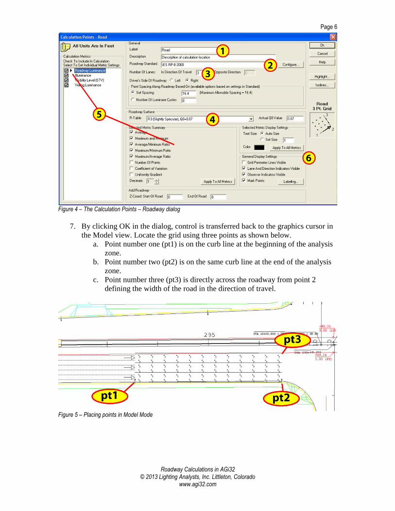
Steps to use AGi32’s Calculation Points – Roadway command Each step references Figure 4 below
1. Enter a Label and Description for this calculation
2. Select the Roadway Standard to be used as the calculation basis
3. Enter the number of lanes in the direction of travel
4. Select the R-Table to describe the pavement surface characteristics
5. Standard calculation metrics for the selected standard are shown on the left. They
can be deselected. Specifics associated with each metric will appear in the area on
the right.
6. Various aesthetic settings can be adjusted if necessary
2 Composite roadway calculations refers to the command capability to place all of the various calculation grids with a single operation: Luminance, Illuminance, Veiling Luminance, Visibility, and more depending on the international standard selected.
Page 6
Roadway Calculations in AGi32
© 2013 Lighting Analysts, Inc. Littleton, Colorado www.agi32.com
Figure 4 – The Calculation Points – Roadway dialog
7. By clicking OK in the dialog, control is transferred back to the graphics cursor in
the Model view. Locate the grid using three points as shown below.
a. Point number one (pt1) is on the curb line at the beginning of the analysis
zone.
b. Point number two (pt2) is on the same curb line at the end of the analysis
zone.
c. Point number three (pt3) is directly across the roadway from point 2
defining the width of the road in the direction of travel.
Figure 5 – Placing points in Model Mode

Page 7
Roadway Calculations in AGi32
© 2013 Lighting Analysts, Inc. Littleton, Colorado www.agi32.com
The end result can be a series of calculation areas within the project, each in position to
analyze the specifics at that location. All luminaires in the project are considered in the
final calculation.
Figure 6 – Model Mode with multiple grids
Roadway Calculations in 3-dimensional environments
AGi32 allows 3-dimensional obstructions or reflecting surfaces to be considered in
roadway calculations. This is not simply illuminance, but all roadway metrics will
consider the shadowing and reflecting properties of objects in the environment. This
allows realistic luminance calculations in applications where reflected or obstructed light
is a factor such as over/under-passes and tunnels. AGi32 is the only program with this
capability.
Starting with the most basic scenario, it is a simple operation to add a roadway surface to
a 2-dimensional model to enable AGi32’s visualization capability. In the image below we
have placed a single polygon object at Z=0 with asphalt reflectance of 10%. The
reflectance is actually immaterial at this point as all reflected light is lost without
additional surfaces to redirect it back down toward the pavement. It does however, allow
a rendered view of the roadway as we now know the diffuse luminance of the pavement
surface due to direct light. In terms of the relationship to the actual roadway calculations,

Page 8
Roadway Calculations in AGi32
© 2013 Lighting Analysts, Inc. Littleton, Colorado www.agi32.com
it is set as surface type: “Pavement Surface- Direct Flux Only” using the Surface Edit
command and has no impact on the results of this calculation.
Figure 7 – Object added for pavement to facilitate rendering
In a more detailed analysis, an overpass and its obstructive and reflective properties can
be considered in the computation of all roadway grids placed in the environment. The
critical procedural element within the software is to define all object surfaces as
“Roadway Contributors.”
Using AGi32’s visualization capability it is easy to assess the need for supplemental
lighting under the overpass (Figure 8).

Page 9
Roadway Calculations in AGi32
© 2013 Lighting Analysts, Inc. Littleton, Colorado www.agi32.com
Figure 8 – Reflective surfaces (objects) considered in the roadway calculations
Roadway Standard Configuration Tool
There are a number of unique calculations associated with each international roadway
standard (North American IES-RP-8-2000, British BSEN 13201-3.2003, European CIE-
140-2000, Australian AS1158.2-2005 and New Zealand NZ1158.2-2005). Consider that
any software tool must compute a multitude of metrics such as: Illuminance, Pavement
Luminance, Veiling Luminance, Visibility Level, Surround Illuminance, Background
Luminance, and more for each specific roadway section to be analyzed. Each
international standard stipulates similar but different calculations and parameters can vary
dramatically.
At Lighting Analysts, we believe we may be the only people that have ever tried to
support all of the popular international roadway standards giving us a unique perspective
when constructing our new roadway calculation engine. Placing all of the standard
calculations in a single software tool begged for underlying code that could handle
variations in calculation specifics such that each standard could simply modify a few
variables and utilize the same engine. We are proud to have achieved this goal, but
perhaps more importantly, we arrived at a landmark decision in the process: Why not

Page 10
Roadway Calculations in AGi32
© 2013 Lighting Analysts, Inc. Littleton, Colorado www.agi32.com
allow individual calculation choices and parameters to be modified on the user level such
that an educated party could feasibly construct a completely new standard by mixing
calculations from all standards and adjusting specifics? Imagine including the British
Semi-cylindrical Illuminance calculation with pavement Luminance calculations from the
IES method! How about adjusting the observer position or the grid of calculation points?
It can all be done. User modifications can be saved as a custom standard and reused as
required in place of published standards.
Steps to define a custom standard Steps refer to Figure 9 below
1. Select the Create button and provide a name for the standard
2. Click the Configure button and select Calculation Metrics to include in the custom
standard
3. Adjust each metric specifics as necessary by selecting the metric on the left side
and editing specifics on the right
Figure 9 – The Roadway Standard Configuration Tool
This is the birth of the Roadway Standard Configuration Tool - what we hope will
become an indispensable research aid for roadway specialists everywhere!