Collecting Bromeliad Seeds for “Save Florida’s Native Bromeliads” Project
Upload
pamela-jacobsCategory
view
214download
0
Collecting Project Problem Requirements
The ATCS Modeling Project: Informal Picture Follows

Data comms.system
Transpondersystem
Radarsystem
Aircraftcomms.
Telephonesystem
Flight plandatabase
Backupposition
processor
Positionprocessor
Comms.processor
Backup comms.processor
Aircraftsimulation
system
Weather mapsystem
Accountingsystem
Controllerinfo. system
Controllerconsoles
Activity loggingsystem
©Ian Sommerville 1995 Software Engineering, 5th edition. Chapter 31. Slide ##
An Example of oneATC SystemArchitecture

Requirements Collection and Organization
• Scope the extent of the (ATCS)
• Collect and organize the following ATCS information:
1. ATC Organizational Structure
2. Roles within the ATC Organization
3. Services/Functions Per ATCS Role
4. Existing (non-human) Supporting ‘Systems’ within the ATC Organization

Layers of ATCS Components – Top Layer
• Problem (Requirements) Layer – The set of all ATC system functions is partitioned into disjoint subsets of functions/services – components
• In the final deliverable in UML/UMP these system functions are called ‘use cases’. The components are represented as ‘packages’.
• Related ATCS components can themselves be encapsulated into packages (of packages) called or stereotyped ‘sub-systems.’
• In the final UML/UMP model all of these components (packages) appear in the Use Cases View Layer.
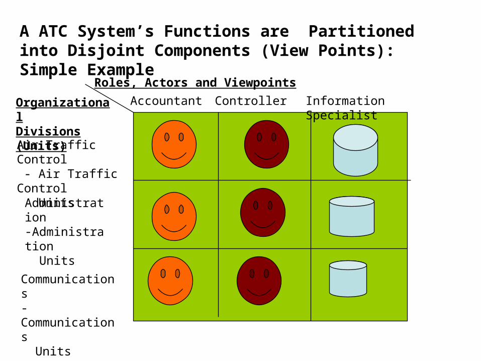
Roles, Actors and Viewpoints
OrganizationalDivisions (Units)
Accountant Controller Information Specialist
Air Traffic Control - Air Traffic Control Units
Administration-Administration Units
Communications-Communications Units
A ATC System’s Functions are Partitioned into Disjoint Components (View Points): Simple Example
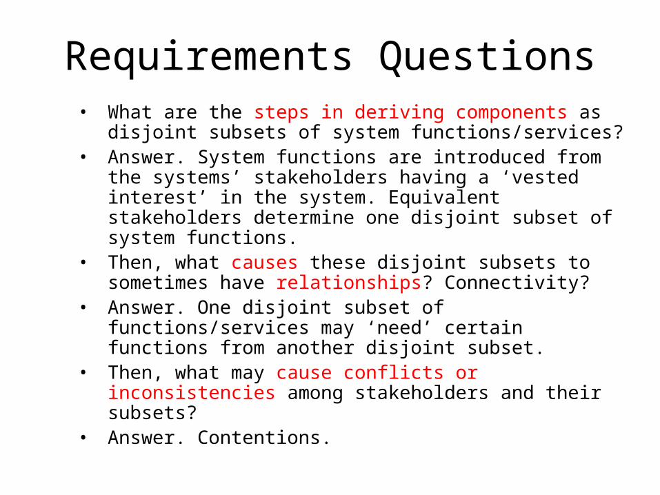
Requirements Questions• What are the steps in deriving components as
disjoint subsets of system functions/services?• Answer. System functions are introduced from the
systems’ stakeholders having a ‘vested interest’ in the system. Equivalent stakeholders determine one disjoint subset of system functions.
• Then, what causes these disjoint subsets to sometimes have relationships? Connectivity?
• Answer. One disjoint subset of functions/services may ‘need’ certain functions from another disjoint subset.
• Then, what may cause conflicts or inconsistencies among stakeholders and their subsets?
• Answer. Contentions.
UML Modeling & Programming Review
Chapters 5-6 Related Material

Originating requirements analysis process
Requirementsvalidation
Domainunderstanding
Prioritization
Requirementscollection
Conflictresolution
Classification
Requirementsdefinition andspecification
Processentry
ATC
VORD Chapter 6
Modeling
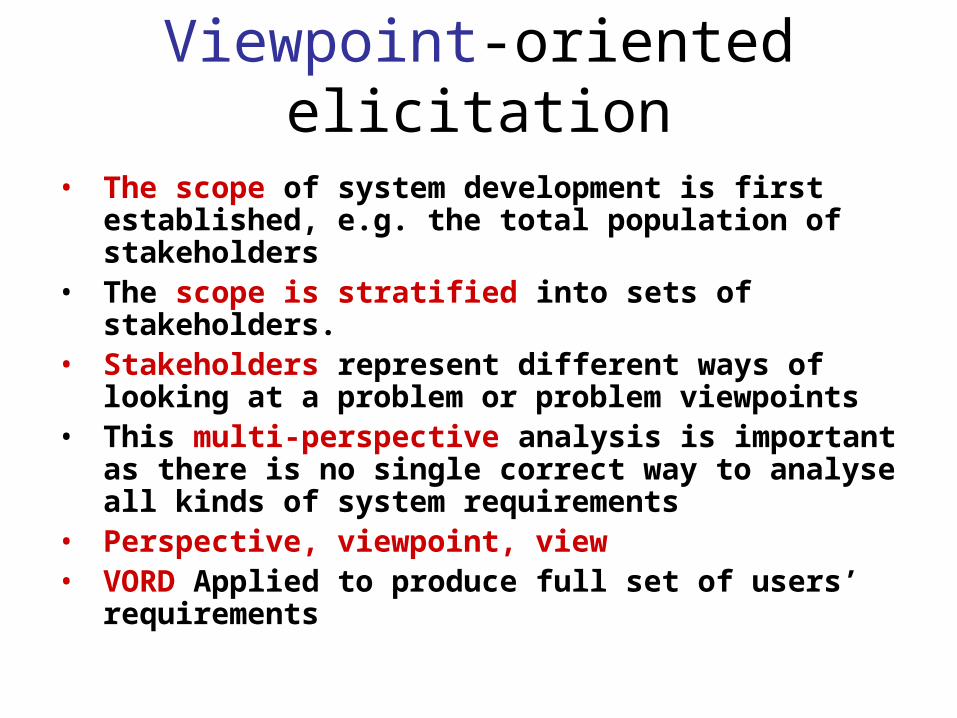
Viewpoint-oriented elicitation• The scope of system development is first
established, e.g. the total population of stakeholders
• The scope is stratified into sets of stakeholders.• Stakeholders represent different ways of looking at
a problem or problem viewpoints• This multi-perspective analysis is important as
there is no single correct way to analyse all kinds of system requirements
• Perspective, viewpoint, view• VORD Applied to produce full set of users’
requirements

Banking ATM system requirements
• The example used here is an auto-teller system which provides some automated banking services
• I use a very simplified system which offers some services to customers of the bank who own the system and a narrower range of services to other customers
• Services include cash withdrawal, message passing (send a message to request a service), ordering a statement and transferring funds
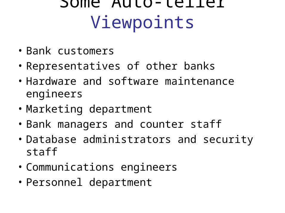
Some Auto-teller Viewpoints
• Bank customers
• Representatives of other banks
• Hardware and software maintenance engineers
• Marketing department
• Bank managers and counter staff
• Database administrators and security staff
• Communications engineers
• Personnel department
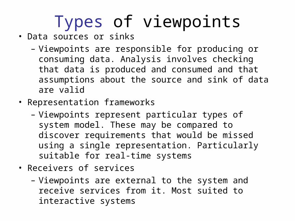
Types of viewpoints• Data sources or sinks
– Viewpoints are responsible for producing or consuming data. Analysis involves checking that data is produced and consumed and that assumptions about the source and sink of data are valid
• Representation frameworks– Viewpoints represent particular types of system
model. These may be compared to discover requirements that would be missed using a single representation. Particularly suitable for real-time systems
• Receivers of services– Viewpoints are external to the system and receive
services from it. Most suited to interactive systems

External viewpoints• Natural to think of end-users as receivers
of system services
• Viewpoints are a natural way to structure requirements elicitation
• It is relatively easy to decide if a viewpoint is valid
• Viewpoints and services may be used to structure non-functional requirements
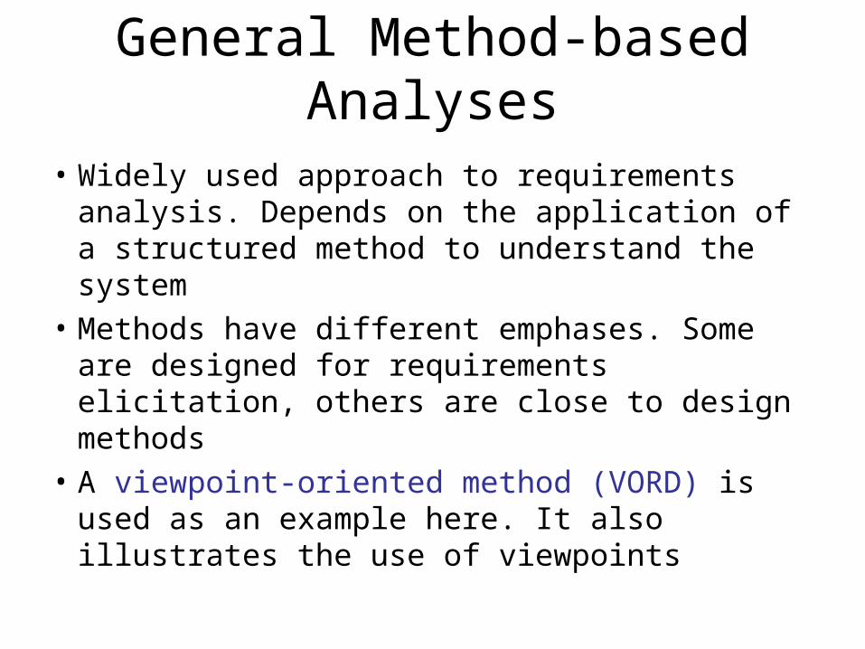
General Method-based Analyses
• Widely used approach to requirements analysis. Depends on the application of a structured method to understand the system
• Methods have different emphases. Some are designed for requirements elicitation, others are close to design methods
• A viewpoint-oriented method (VORD) is used as an example here. It also illustrates the use of viewpoints

The VORD method: Our Method
Viewpointidentification
Viewpointstructuring
Viewpointdocumenta tion
Viewpointsystem mapping
Start Here! Finish Modeling!

VORD process model activities
• ATMS Viewpoint identification– Discover viewpoints which receive system services
and identify the services provided to each viewpoint• ATMS Viewpoint structuring
– Group related viewpoints into a hierarchy. Common services are provided at higher-levels in the hierarchy
• ATMS Viewpoint documentation– Refine the description of the identified viewpoints and
services• ATMS Viewpoint-system mapping
– Transform the analysis to a UML object-oriented design
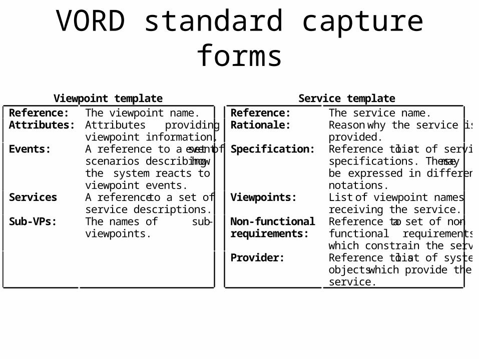
VORD standard capture formsViewpoint template Service template
Reference: The viewpoint name. Reference: The service name.Attributes: Attributes providing
viewpoint information.Rationale: Reason why the service is
provided.Events: A reference to a set of event
scenarios describing howthe system reacts toviewpoint events.
Specification: Reference to a list of servicespecifications. These maybe expressed in differentnotations.
Services A reference to a set ofservice descriptions.
Viewpoints: List of viewpoint namesreceiving the service.
Sub-VPs: The names of sub-viewpoints.
Non-functionalrequirements:
Reference to a set of non -functional requirementswhich constrain the service.
Provider: Reference to a list of systemobjects which provide theservice.

ATMS Viewpoint identificationQuerybalance
Gettransactions
Cashwithdrawal
Transactionlog
Machinesupplies
Cardreturning
Remotesoftwareupgrade
Ordercheques
Userinterface
Accountinformation
Messagelog
Softwaresize Invalid
userSystem cost Printe
r Security
Cardretention
Stolencard
Orderstatement
Remotediagnostics
ReliabilityUpdateaccount
Fundstransfer
Messagepassing
Cardvalidation
Customerdatabase
Manager
Accountholder
Foreigncustomer
Hardwaremaintenance
Bankteller

ATMS Viewpoint service information
FOREIGNCUSTOMER
Withdraw cashQuery balance
Service list
Withdraw cashQuery balanceOrder chequesSend messageTransaction listOrder statementTransfer funds
Service list
Run diagnosticsAdd cashAdd paperSend message
Service list
ACCOUNTHOLDER
BANKTELLER

ATMS Viewpoint data/control
Start transactionCancel transactionEnd transactionSelect service
Card detailsPINAmount requiredMessage
Control input Data inputACCOUNTHOLDER

ATMS Viewpoint hierarchy: Information Structure
EngineerManagerTellerForeign
customerAccountholder
Services
Order chequesSend messageTransaction listOrder statementTransfer funds
Customer Bank staff
All VPs
Services
Query balanceWithdraw cash
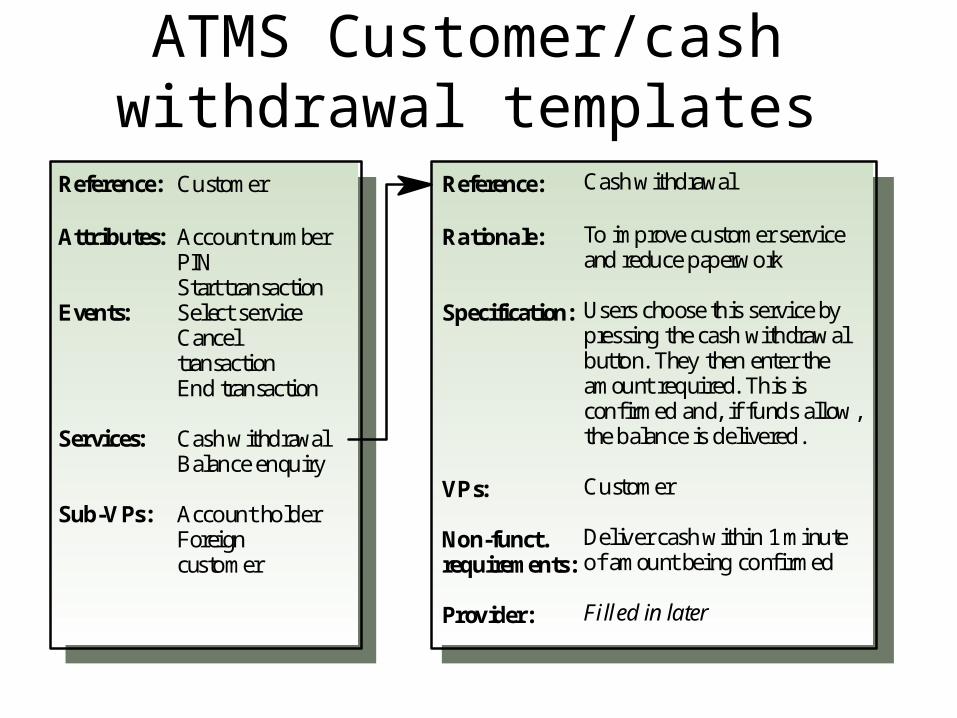
ATMS Customer/cash withdrawal templates
Customer
Account numberPINStart transactionSelect serviceCanceltransactionEnd transaction
Cash withdrawalBalance enquiry
Account holderForeigncustomer
Reference:
Attributes:
Events:
Services:
Sub-VPs:
Cash withdrawal
To improve customer serviceand reduce paperwork
Users choose this service bypressing the cash withdrawalbutton. They then enter theamount required. This isconfirmed and, if funds allow,the balance is delivered.
Customer
Deliver cash within 1 minuteof amount being confirmed
Filled in later
Reference:
Rationale:
Specification:
VPs:
Non-funct.requirements:
Provider:
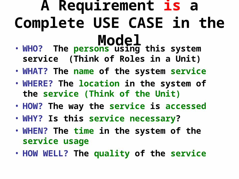
A Requirement is a Complete USE CASE in the Model
• WHO? The persons using this system service (Think of Roles in a Unit)
• WHAT? The name of the system service• WHERE? The location in the system of the
service (Think of the Unit)• HOW? The way the service is accessed• WHY? Is this service necessary?• WHEN? The time in the system of the service
usage• HOW WELL? The quality of the service

Missing Use Case Information• WHO? Is this missing? View Point/Actor
Classes?• WHAT? Is this missing? Service/Use Case
Name?• WHERE? Is this missing? Unit/Package
Name?• HOW? Is this missing? Scenario/Script?• WHY? Is this missing? Rationale?• WHEN? Is this missing? Before, During?
After?• HOW WELL? Is this missing? Performance?

QUESTION. UML Diagram Model Programming INPUT {See Figs 5.1, 5.10, 5.11 and 5.12 Row 1}Given the following paragraph of Requirements (index numbered ‘shall’ simple sentence format) for a Car Dashboard Display system, translate these requirements into an equivalent UML Use Cases model program. In doing the translation, first translate each sentence in the given requirements into equivalent UML Use Case Diagram modeling format. Note: Your answer here MUST be diagrammatically correct Rational Rose ‘code’, i.e. must pass through the model and access violations checkers. 1. There shall be a car dashboard display. 1.1. The car dashboard display shall be comprised of warning lights. 1.1.1. The warning lights shall be oil pressure level, doors state and fuel level. 1.1.2. The services of warning lights shall be turn_on warning lights and turn_off warning lights.
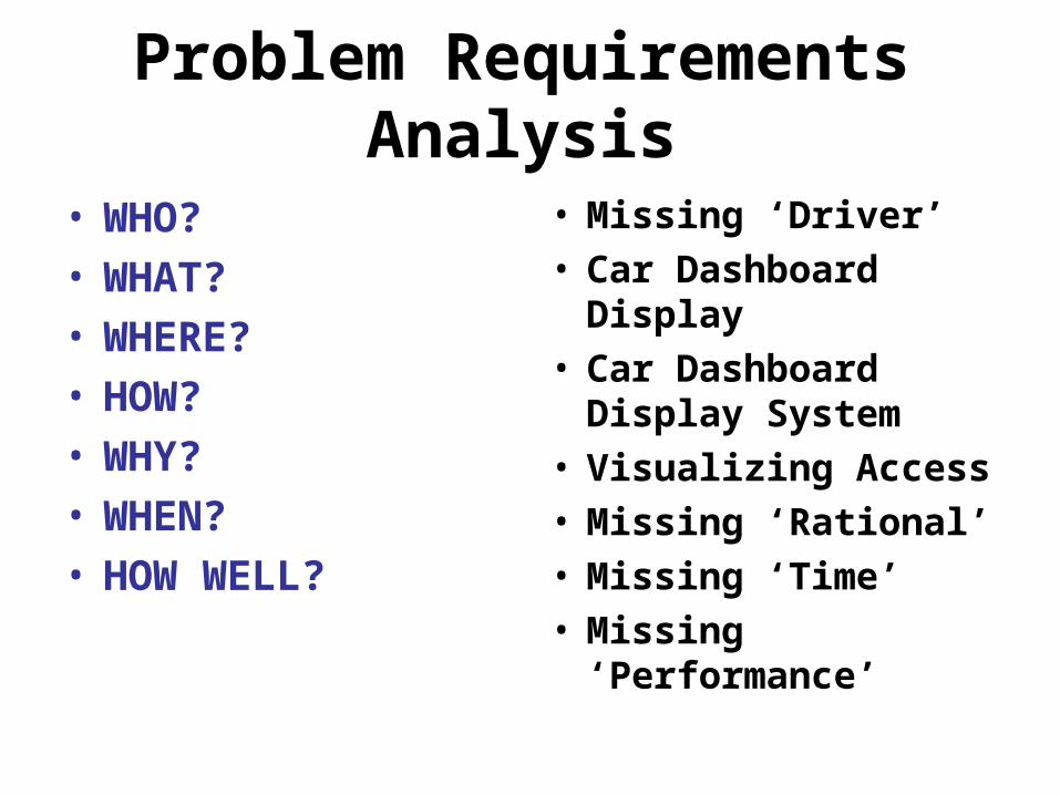
Problem Requirements Analysis
• WHO?• WHAT?• WHERE?• HOW?• WHY?• WHEN?• HOW WELL?
• Missing ‘Driver’• Car Dashboard
Display• Car Dashboard
Display System• Visualizing Access• Missing ‘Rational’• Missing ‘Time’• Missing
‘Performance’

Services Included in Car Dashboard Display (CDD)
• Warning Lights• Specialized Kinds of
Warning Lights• Specialized Services
of Each Warning Light
• Parts of CDD• Oil Pressure Level,
Doors State, Fuel Level
• Turn_On, Turn_Off
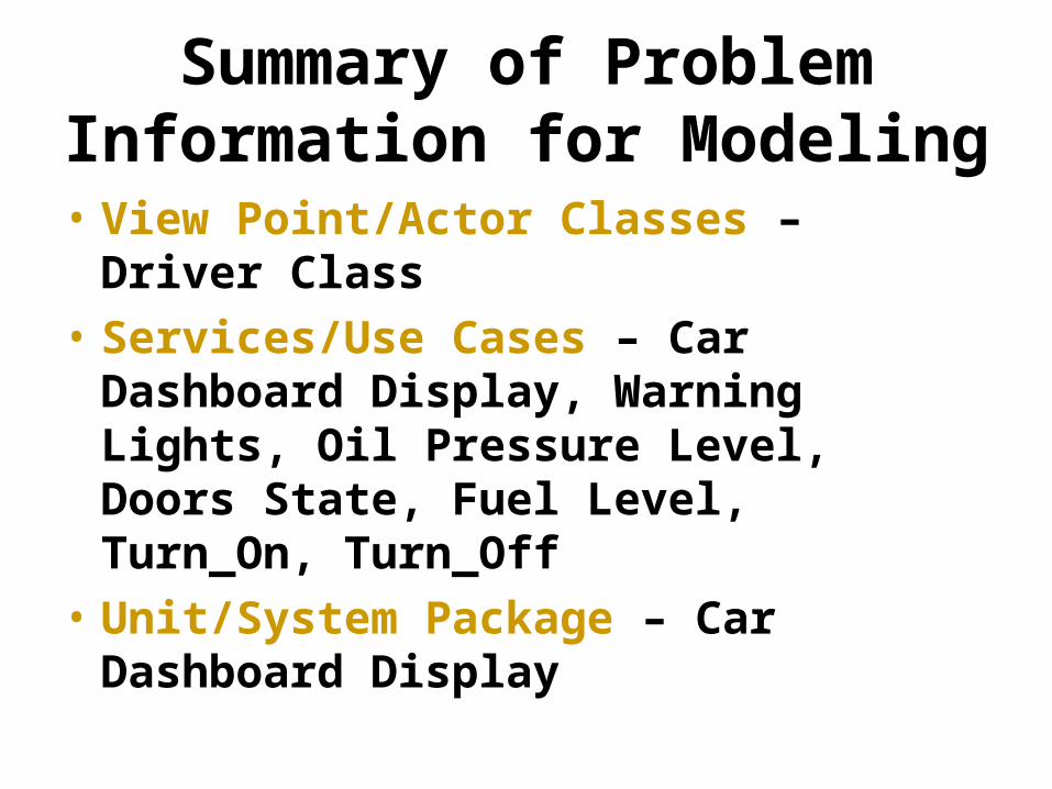
Summary of Problem Information for Modeling
• View Point/Actor Classes – Driver Class
• Services/Use Cases – Car Dashboard Display, Warning Lights, Oil Pressure Level, Doors State, Fuel Level, Turn_On, Turn_Off
• Unit/System Package – Car Dashboard Display


UML Program Structures
• Generalization/Specialization
• Aggregation/Inclusion/Whole-Parts
• Access/Unidirectional Association
• Nested Packages/System-Subsystems
• View these in the Tools/Create Menu and Vertical Programming Bar