COLEMAN®-MACH® AIR CONDITIONERS - RV...
12
COLEMAN®-MACH® AIR CONDITIONERS INSTALLATION INSTRUCTIONS FOR 8430*6301 CHILLGRILLE™ STRAIGHT THROUGH DUCTED PLENUM KIT 8330-752 CONTROL BOX KIT (12 VDC COOL ONLY) 9330C755 CONTROL BOX KIT (12 VDC HEAT READY) 8530-750 CONTROL BOX KIT (24 VAC COOL ONLY) 9530A751 CONTROL BOX KIT (12 VDC HEAT PUMP) 9430A751 ZONE CONTROL KIT (12 VDC COOL ONLY) 9430A755 ZONE CONTROL KIT (12 VDC HEAT READY) 9630A751 ZONE CONTROL KIT (12 VDC HEAT PUMP) DESIGNED AND MANUFACTURED BY THE MAKERS OF COLEMAN®-MACH® AIR CONDITIONERS RV Products Division Coleman is a registered trademark of The Coleman Company, Inc. used under license. Mach is a registered trademark.
Transcript of COLEMAN®-MACH® AIR CONDITIONERS - RV...
COLEMAN®-MACH® AIR CONDITIONERS
INSTALLATION INSTRUCTIONS
FOR
8430*6301 CHILLGRILLE™
STRAIGHT THROUGH DUCTED PLENUM KIT
8330-752 CONTROL BOX KIT (12 VDC COOL ONLY)
9330C755 CONTROL BOX KIT (12 VDC HEAT READY)
8530-750 CONTROL BOX KIT (24 VAC COOL ONLY)
9530A751 CONTROL BOX KIT (12 VDC HEAT PUMP)
9430A751 ZONE CONTROL KIT (12 VDC COOL ONLY)
9430A755 ZONE CONTROL KIT (12 VDC HEAT READY)
9630A751 ZONE CONTROL KIT (12 VDC HEAT PUMP)
DESIGNED AND MANUFACTURED BY THE MAKERS OF
COLEMAN®-MACH® AIR CONDITIONERS
RV Products Division
Coleman is a registered trademark of The Coleman Company, Inc. used under license. Mach is a registered trademark.
2
TABLE OF CONTENTS
1. Warnings . . . . . . . . . . . . . . . . . . . . . . . . . . . . . . . . . . . . . . . . . . . . . . . . . . . . . . . . . . . . . . . . . . . . 2
2. Package Contents . . . . . . . . . . . . . . . . . . . . . . . . . . . . . . . . . . . . . . . . . . . . . . . . . . . . . . . . . . . . . 2
3. General Information and Requirements . . . . . . . . . . . . . . . . . . . . . . . . . . . . . . . . . . . . . . . . . . 3
4. Ceiling Plenum Installation Requirement . . . . . . . . . . . . . . . . . . . . . . . . . . . . . . . . . . . . . . . . . 3
5. Control Box Kits . . . . . . . . . . . . . . . . . . . . . . . . . . . . . . . . . . . . . . . . . . . . . . . . . . . . . . . . . . . . . . 4
6. Control Box Kits (Zone) . . . . . . . . . . . . . . . . . . . . . . . . . . . . . . . . . . . . . . . . . . . . . . . . . . . . . . . . 4
7. Wall Thermostats . . . . . . . . . . . . . . . . . . . . . . . . . . . . . . . . . . . . . . . . . . . . . . . . . . . . . . . . . . . . . 5
8. Supply Ducting and Registers . . . . . . . . . . . . . . . . . . . . . . . . . . . . . . . . . . . . . . . . . . . . . . . . . . . 5
9. Routing Thermostat Wiring . . . . . . . . . . . . . . . . . . . . . . . . . . . . . . . . . . . . . . . . . . . . . . . . . . . . 5
10. Routing Thermostat Wiring (Zone) . . . . . . . . . . . . . . . . . . . . . . . . . . . . . . . . . . . . . . . . . . . . . . 6
11. Routing 115 VAC Wiring . . . . . . . . . . . . . . . . . . . . . . . . . . . . . . . . . . . . . . . . . . . . . . . . . . . . . . . 6
12. Ceiling Plenum Mounting . . . . . . . . . . . . . . . . . . . . . . . . . . . . . . . . . . . . . . . . . . . . . . . . . . . . . . 8
13. Installing the Control Box . . . . . . . . . . . . . . . . . . . . . . . . . . . . . . . . . . . . . . . . . . . . . . . . . . . . . . 8
14. Installing the Control Box (Zone) . . . . . . . . . . . . . . . . . . . . . . . . . . . . . . . . . . . . . . . . . . . . . . . . 9
15. Installing the Heater Assembly . . . . . . . . . . . . . . . . . . . . . . . . . . . . . . . . . . . . . . . . . . . . . . . . . . 11
16. Install Air Grille Assembly . . . . . . . . . . . . . . . . . . . . . . . . . . . . . . . . . . . . . . . . . . . . . . . . . . . . . 12
1. WARNINGS
IMPORTANT NOTICE
These instructions are for the use of qualified individuals
specially trained and experienced in installation of this
type equipment and related system components.
Installation and service personnel are required by some
states to be licensed. PERSONS NOT QUALIFIED
SHALL NOT SERVICE THIS EQUIPMENT.
WARNING
Improper installation may damage equipment, can create
a hazard and will void the warranty.
The use of components not tested in combination with
these units will void the warranty, may make the
equipment in violation of state codes, may create a hazard
and may ruin the equipment.
WARNING – SHOCK HAZARD
To prevent the possibility of severe personal injury or
equipment damage due to electrical shock, always be sure
the electrical power to the appliance is disconnected
during installation.
CAREFULLY FOLLOW ALL INSTRUCTIONS
AND WARNINGS IN THIS BOOKLET TO AVOID
DAMAGE TO THE EQUIPMENT, PERSONAL
INJURY OR FIRE.
NOTE
The words “Shall” or “Must” indicate a requirement
which is essential to satisfactory and safe product
performance.
The words “Should” or May” indicate a
recommendation which is not essential and not
required, but which may be useful or helpful.
2. PACKAGE CONTENTS
1) Forward Supply Duct
1) Duct Seal Strip
1) Duct Divider Board
1) Divider Board Gasket
1) Chillgrille Assembly Consisting of:
1) Chute/Supply Air Plate
1) Shroud Assembly
2) Filters
2) Grilles
1) Mount Frame
1) Small Parts Package Consisting Of:
4 - Bolts
10 - Screws – 3/8” Length
4 - Springs
4 - Washers
3
3. GENERAL INFORMATION AND
REQUIREMENTS
The flush mount ceiling plenum is designed for application in
systems that utilize field fabricated (OEM supplied) cold air
ducting. The ducting must be routed through the ceiling
cavity (between the interior ceiling and roof). Ducting
specifications are given in the section labeled “Supply Ducting
and Registers”.
This system utilizes a single, non-ducted centrally located
return air opening. The return air opening is contained within
the ceiling plenum. The ceiling plenum must be located
directly below the roof opening used for mounting the roof top
unit.
All manual controls have been removed from the ceiling
plenum. They have been replaced with control relays. The
relays are mounted in the electrical box of the ceiling plenum.
The relays contain 12 VDC coils (which may be energized by
a wall mounted thermostat), with contacts that control the 115
VAC used to power the roof top unit.
A low voltage controller controls all air conditioning
functions. The low voltage controller controls a 12 VDC
electrical circuit, which is used to energize the relays in the
ceiling plenum. The low voltage controller that Airxcel, Inc.
provides for the system may be a combination (Heat/Cool).
These low voltage controllers are capable of operating both
the roof top air conditioner and any furnace with a 12 VDC
control circuit of 1 amp or less (continuous current).
All air conditioning equipment is subject to freeze up when
evaporator air flow is sufficiently reduced. Ducting of any
length creates potential for reduced evaporator air flow and
system freeze up. To protect both the installer and Airxcel,
Inc. from conditions that promote reduced air flow and system
freeze up, Airxcel, Inc. has equipped the ceiling plenum
compressor control circuit with a low temperature probe. The
low temperature probe monitors the temperature of the air
conditioner evaporator coil. When the temperature of the
evaporator coil drops below 28 degrees F, the switch will
open, stopping compressor operation. Compressor operation
will resume once the evaporator warms to 55 degrees F.
IMPORTANT
The low temperature sensor is part of the ceiling plenum
electrical circuit. The probe must be inserted into the
evaporator coil of the roof top unit by the installer when
bolting the ceiling plenum to the roof top unit.
4. CEILING PLENUM INSTALLATION REQUIREMENT
1. The ceiling plenum must be installed under the roof
opening.
The ceiling plenum bolts below the roof top unit.
Compression of the framed ceiling cavity between
the roof top unit and the ceiling plenum is what holds
both components in place.
2. Ceiling cavity depth (the measurement from the
ceiling to the roof – maximum 5”).
3. Provided with the ceiling plenum is a divider board
which is used to separate the conditioned air from the
return air supply.
4. The 115 VAC service for the roof top unit must be
routed into the ceiling plenum. To prevent wire
pinching and to promote ease of installation,
allowances must be made for routing the 115 VAC
supply wiring into the front of the roof opening.
5. The wirebox has a 9 pin receptacle extending from
the front. This mates with the roof unit 115 volt
electrical conduit. When making this connection,
verify that the plugs are properly aligned and have
snapped together securely.
6. The wirebox for the heat/cool units will have a two
pin receptacle which mates with the umbilical plug
from the heater assembly.
7. LOW VOLTAGE CONTROL WIRING (WALL
THERMOSTAT)
A. A low voltage terminal strip on the front of
the box connects to the low voltage control
wires. The wires attach by 1/4" quick
connects.
B. The low voltage control wiring must be run
from the wall thermostat mounting location
to the wirebox low voltage terminals. To
prevent wire pinching and to promote ease
of installation, allowances must be made for
routing the low voltage wiring into the front
of the opening.

4
Standard Control Box
Zone Control Box
Plenum Terminal
Designation
Thermostat Wire
Connection
Function of Low Voltage Terminal Extending
From Ceiling Plenum
R+ Red Provides +12 VDC to upper unit control box
Cool Shed
(2 Terminals)
Removing jumper wire will allow system to be connected to N.C.
contacts of a load shed system
Heat Shed
(2 Terminals)
Removing jumper wire will allow system to be connected to N.C.
contacts of a load shed system
Room (2 Terminals) The remote room temperature sensor attaches here*
Freeze (2 Terminals) Freeze sensor attaches here
Gen Allows system to connect to an automatic start generator system
B- Blue Provides -12 VDC to upper unit control box
Sig 1 Purple Communication line between upper unit control box and thermostat
Sig 2 Black Communication line between upper unit control box and thermostat
* Zone 1 has option of using thermostat as room sensor
5. CONTROL BOX KITS
1. 8330-752 – 12 VDC Controlled, Cool Only
This kit consists of a control box assembly. The evaporator
freeze sensor is shipped in an envelope for installation by
quick connects to terminal strip “Freeze”.
2. 9330C755 – 12 VDC Controlled, Heat Ready
This kit consists of a control box assembly. The evaporator
freeze sensor is shipped in an envelope for installation by
quick connects to terminal strip “Freeze”. The heater
assembly for the 47000 series units is 47233*4551. The
heater assembly for the 48000 and 49000 series units is
9233*4551. They are purchased separately.
3. 8530-750 – 24 VAC Controlled, Cool Only
This kit is similar to the 8330-752 with the exception of a
transformer that is attached to the box assembly.
4. 9530A751 – 12 VDC Controlled, Heat Pump
This kit is similar to the 9330C755 but is wired for the heat
pump function.
Cool Only
Boxes
Plenum Terminal
Designation
Thermostat Wire
Connection
Function of Low Voltage Terminal
Extending From Ceiling Plenum
Heat Ready
Boxes
Yes B BLUE Completes -12 VDC circuit for all relays Yes
Yes Y YELLOW Energizes coil on Compressor Relay Yes
Yes GH GREEN Energizes coil on High Fan Relay Yes
Yes GL GRAY Energizes coil on Low Fan Relay Yes
Yes FREEZE Evaporator Freeze Sensor Connections Yes
Yes FREEZE
No W WHITE Energizes coil on Heat Relay Yes
5
6. CONTROL BOX KITS (ZONE)
1. 9430A751 – 12 VDC Zone Controlled, Cool Only
This kit consists of a control box assembly. The evaporator
freeze sensor is shipped in an envelope for installation by
quick connects to terminal strip marked “FREEZE”.
2. 9430A755 – 12 VDC Controlled, Heat Ready
This kit consists of a control box. The evaporator freeze
sensor is shipped in an envelope for installation by quick
connects to terminal strip marked “FREEZE”. The heater
assembly for the 47000 series units is 47233*4551. The
heater assembly for the 48000 and 49000 series units is
9233*4551. They are purchased separately.
3. 9630A751 – 12 VDC Zone Controlled, Heat Pump
This kit consists of a control box assembly. The evaporator
freeze sensor is shipped in an envelope for installation by
quick connects to terminal strip marked “FREEZE”. Backup
electric heat is available as an optional kit. The heater
assembly for the 47000 series units is 47233*4551. The
heater assembly for the 48000 and 49000 series is 9233*4551.
They are purchased separately.
7. WALL THERMOSTATS
1. Locate and install the thermostat per instructions
found with the thermostat.
2. For 12 VDC thermostats, it is required that the
thermostat 12 volt negative connection be routed
directly from the converter or battery. It is highly
desirable to provide 12 volt control power from the
battery side of the converter. These precautions
should prevent control problems.
3. For the 24 VAC thermostat, keep in mind that if the
application will involve operation while in motion or
subject to vibration, an electromechanical thermostat
must not be used as electromechanical contacts will
“chatter” the compressor relay if used in high
vibration applications. For applications subject to
vibration, an electronic wall thermostat must be used.
Airxcel, Inc. part numbers are 8330B3241 or
7330B3441.
4. The sub-base used with heat/cool and heat pump
thermostats replaces the mount plate provided with
the thermostat. The thermostat body snaps onto the
sub-base.
8. SUPPLY DUCTING AND REGISTERS
A. Ducting
1. The field fabricated supply ducting must open into
both ends of the ceiling plenum. Two ducts are
required; one duct attached to the front, and one to
the rear of the plenum (See Figure 1).
2. Each duct must have a minimum height of 1 3/4”,
maximum height cannot exceed 2 1/2 inches. Total
free area inside each duct must be no less than 10
square inches.
NOTE
To decrease restriction and increase air flow,
the ducting should make as few bends and
turns as possible. When corners or turns are
required, we recommend that you radius the
corners to keep air flow at a maximum.
Ten (10) square inches of free area per duct is the
minimum requirement, larger ducting will improve
air flow and system performance.
3. Where ducting secures to the ceiling plenum,
maximum width is 6 inches.
4. All field fabricated cold air supply ducting must be
insulated and must have a vapor barrier.
IMPORTANT
Insulation reduces cooling loss and helps
prevent water staining of the vehicle ceiling
due to moisture condensation.
B. Registers
Supply (cold air) registers should have a minimum
discharge area of 48 square inches per system, or 24
square inches per duct. A minimum of 6 is
recommended.

6
9. ROUTING THERMOSTAT WIRING
1. Following the instructions packed with the
thermostat, determine a location for thermostat
mounting.
2. Following Airxcel, Inc. low voltage wiring
specifications and all local and national electrical
codes:
A. Route the thermostat 12 VDC supply wiring
from the power source to the thermostat
mounting location.
Two wires are required:
One supply lead must be +12 VDC and red
in color.
The second supply lead must be -12 VDC
and blue in color.
B. To protect the wall mount thermostat from
over-current damage, a 2 amp fuse has been
provided with the thermostat.
C. Route the thermostat control wiring from the
thermostat mounting location into the front
of the ceiling plenum opening.
Four (4) wires are required (5 wires for
heat/cool boxes). These wires are as
follows:
(1) Blue wire for -12 VDC circuit
(1) Yellow wire for compressor circuit
(1) Green wire for high fan circuit
(1) Gray wire for low fan circuit
(1) White wire for heat circuit
3. Airxcel, Inc. low voltage wiring specifications:
A. All low voltage wiring should be 18 gauge
minimum.
B. Low voltage wiring must be routed into the
front side of the ceiling plenum opening.
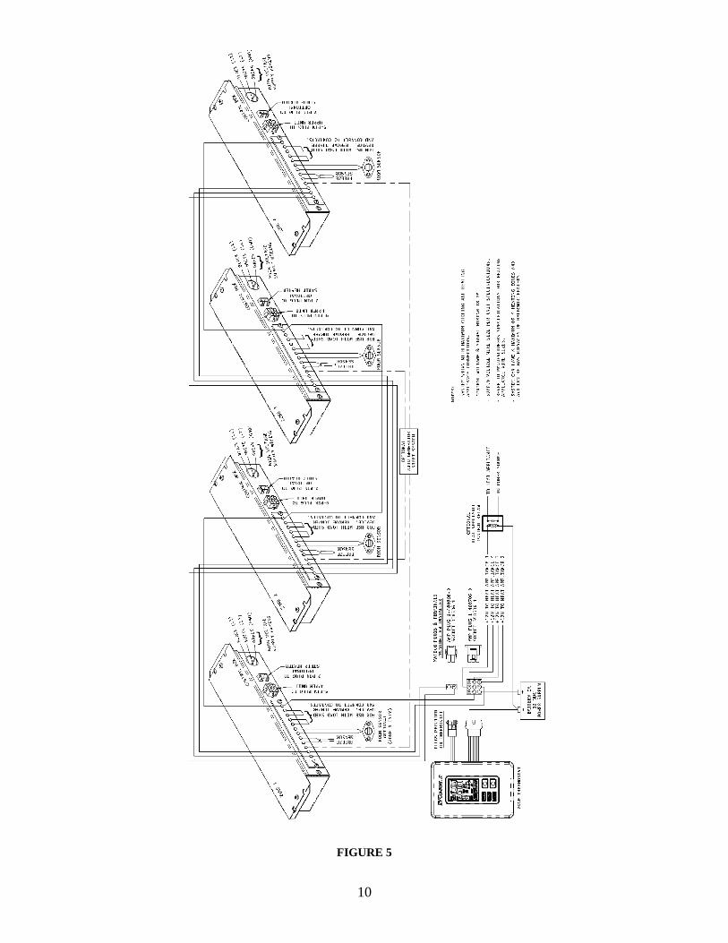
10. ROUTING THERMOSTAT WIRING (ZONE)
1. Following the instructions packed with the
thermostat, determine a location for thermostat
mounting.
2. Following Airxcel, Inc. low voltage wiring
specifications and all local and national electrical
codes:
A. Route the thermostat control wiring from the
thermostat mounting location into the front
of the ceiling plenum opening.
These wires are as follows:
(1) Red wire to +12 VDC circuit (R+)
(1) Blue wire to -12 VDC circuit (B-)
(1) Purple wire to communication
signal (Sig 1)
(1) Black wire to communication
signal (Sig 2)
(1) Any color for auto generator start
(optional) (Gen)
(2) Any color for room temperature
sensor (zone 1 optional, required
for other zones)
(1) For each heating appliance
(Up to 4)
(2) Any color for cool load shed
(optional)
(2) Any color for heat load shed
(optional)
B. See Figure 5 for wiring requirements for
multiple zones.
3. Airxcel, Inc. low voltage wiring specifications:
A. All low voltage wiring should be no
smaller than 18 gauge.
B. Low voltage wiring must be routed into
the front side of the ceiling plenum opening.
C. Low voltage wiring should not be routed
with high voltage wiring.
D. If low voltage and high voltage wires must
cross, they should do so at right angles from
one another.
7
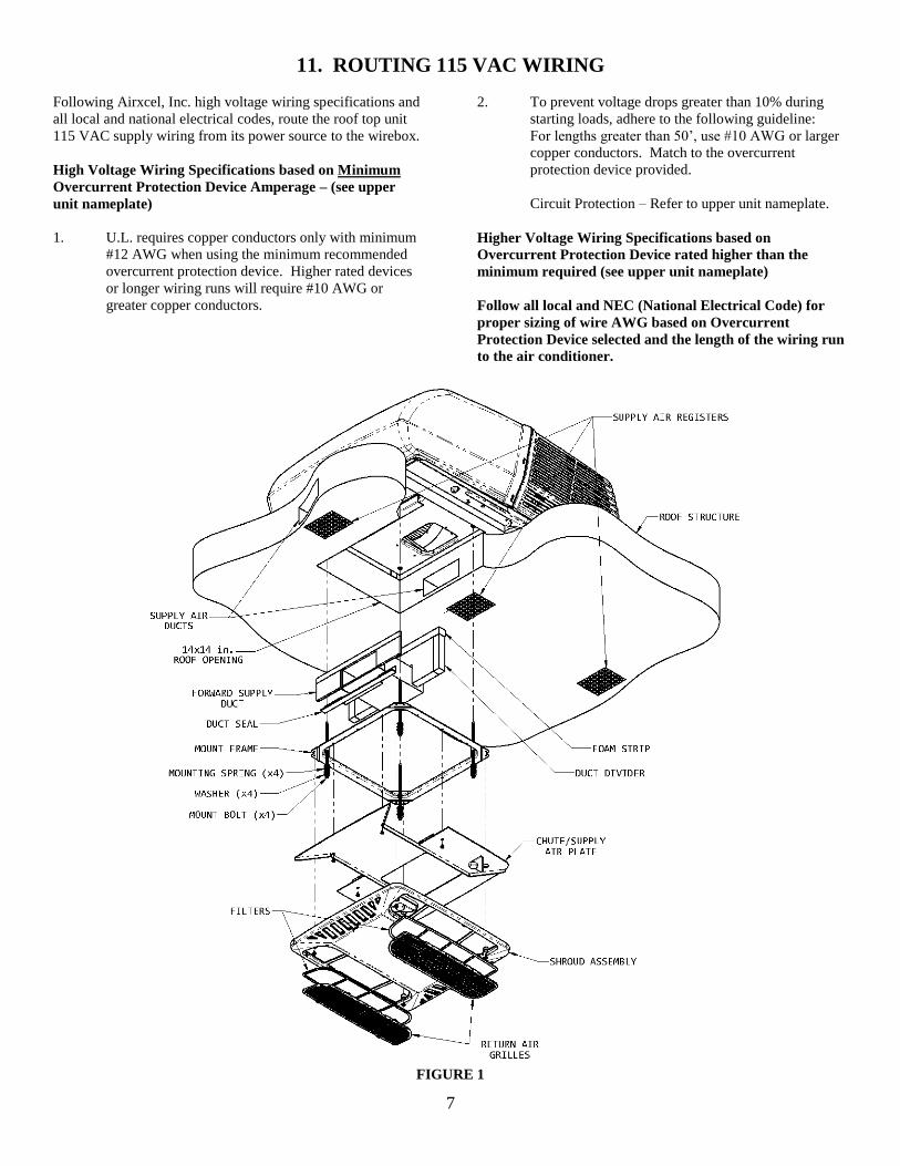
11. ROUTING 115 VAC WIRING
Following Airxcel, Inc. high voltage wiring specifications and
all local and national electrical codes, route the roof top unit
115 VAC supply wiring from its power source to the wirebox.
High Voltage Wiring Specifications based on Minimum
Overcurrent Protection Device Amperage – (see upper
unit nameplate)
1. U.L. requires copper conductors only with minimum
#12 AWG when using the minimum recommended
overcurrent protection device. Higher rated devices
or longer wiring runs will require #10 AWG or
greater copper conductors.
2. To prevent voltage drops greater than 10% during
starting loads, adhere to the following guideline:
For lengths greater than 50’, use #10 AWG or larger
copper conductors. Match to the overcurrent
protection device provided.
Circuit Protection – Refer to upper unit nameplate.
Higher Voltage Wiring Specifications based on
Overcurrent Protection Device rated higher than the
minimum required (see upper unit nameplate)
Follow all local and NEC (National Electrical Code) for
proper sizing of wire AWG based on Overcurrent
Protection Device selected and the length of the wiring run
to the air conditioner.
FIGURE 1

8
12. CEILING PLENUM MOUNTING
1. Place the air conditioner over the roof opening (See
Figure 1).
2. Note that the duct divider has been pre-cut to
conform to the supply duct. These pre-cuts are
centered in the divider board. The board width will
not need adjustment, as the attached foam allows
accommodation of any width between 14” and 15”.
Measure the distance between the ceiling and the
basepan. From this dimension, subtract ½ inch.
With this dimension, cut the divider height. Always
trim off excess height from the top (See Figure 1).
3. Install the adhesive backed foam strip onto the top
edge of the duct divider. Wedge the divider between
the walls of the roof opening and against the upper
unit basepan. You have now created an insulated and
vapor sealed barrier to separate unit supply air from
unit return air. When installed, the divider board
should fit very snug all around.
4. Insert the forward supply duct assembly into the
divider board cutout. Gently ease the duct assembly
forward until the flange contacts the front edge of the
roof opening.
Align the bottom of the supply duct with the duct
opening. Secure the duct with two screws provided
in the mount kit small parts package. Using the duct
seal found in the mount kit, seal off the gap which
exists at the bottom of the duct flange where it abuts
the bottom ceiling duct opening (See Figure 1).
5. Install the ceiling assembly mount frame using the
four bolts, washers and springs (See Figure 1).
Tighten only until the spring coils have achieved
closure.
13. INSTALLING THE CONTROL BOX
1. Remove the control box assembly cover which may
be held by two sheet metal screws. Feed the field
lead wires and ground through the strain relief found
with the control box.
2. Attach black supply conductor to black “pigtail” lead,
white to white and ground to green with wire nuts
provided in control box kit.
3. Insure that no bare wires can come into contact with
live electrical parts and that wires cannot be pinched
between the control box sides and lid. Insert the
strain relief into the control box entry hole to secure
the field wiring. Reinstall the control box lid.
4. Attach the thermostat wires to the control box per
illustrations below:
A. Control Box 8330-752
B. Control Box 9330C755, 9530A751
C. Control Box 8530-750

9
5. Connect the roof unit 115 volt electrical conduit to
the wirebox 9 pin receptacle and verify that the plugs
are properly aligned and have snapped together
securely.
6. Locate the two machine screws inside the evaporator
cover of the upper unit. Align the control box over
the screws and use the wing nuts supplied with the
control box to secure it to the upper unit enclosure.
For the 47000 series units, see Figure 8.
7. Insert the evaporator freeze sensor between
evaporator fins near the bottom center of the
evaporator and between the bottom two tubes (See
Figure 2). Insert straight in until contacting the
staggered tube directly in back of the insertion point.
When contact has been made, elevate the exposed
end of the sensor approximately 45 degrees, then
continue insertion at a 45 degree angle until the
sensor is completely embedded into the evaporator.
FIGURE 2
14. INSTALLING THE CONTROL BOX (ZONE)
1. Remove the control box assembly’s cover which is
held by two sheet metal screws.
2. Set the “zone” jumper to the proper zone position for
the particular position the air conditioner or heat
pump will be in the coach (Refer to Figure 3 – Zone
1 is shown). Zones should be numbered from the
front to the back of the coach with Zone 1 in front.
3. Set the “HP”/”NON HP” jumper to “HP” if the unit
is a heat pump or to “NON HP” if the unit is not a
heat pump (Refer to Figure 3 – Non HP is shown).
4. Feed the field lead wires and ground through the
strain relief found with the control box then through
the 7/8” hole in the side of the box.
FIGURE 3
5. Wire nut the black field power conductor to the
stripped black 12-gauge wire in the control box.
6. Wire nut the white field power conductor to the
stripped white 12-gauge wire in the control box.
7. Wire nut the ground field power conductor to the
stripped green ground wire in the control box.
8. Insure that no bare wires can come into contact with
live electrical parts and that wire cannot be pinched
between the control box sides and lid. Insert the
strain relief into the control box entry hole to secure
the field wiring. Reinstall the control box lid.
9. Attach the thermostat wires to Zone 1 control box per
the illustration below (Refer to Figure 4):
FIGURE 4
10
FIGURE 5
11
Zone 2 is wired in by jumpering from Sig 1, Sig 2, B- and R+
on Zone 1 box to Zone 2 box. Zone 3 is wired in by
jumpering from Sig 1, Sig 2, B- and R+ on Zone 2 box to
Zone 3 box. Zone 4 is wired in by jumpering from Sig 1, Sig
2, B- and R+ on Zone 3 box to Zone 4 box (See Figure 5).
10. Connect the roof unit 115 volt electrical conduit to
the wirebox 9 pin receptacle and verify that the plugs
are properly aligned and have snapped together
securely.
11. Position the control box over the screws and use the
wing nuts to fasten the control box to the upper unit
enclosure. For the 47000 series units, see Figure 8.
12. Insert the evaporator freeze sensor between
evaporator fins near the bottom center of the
evaporator and between the bottom two tubes (See
Figure 2). Insert straight in until contacting the
staggered tube directly in back of the insertion point.
When contact has been made, elevate the exposed
end of the sensor approximately 45 degrees, then
continue insertion at a 45 degree angle until the
sensor is completely embedded into the evaporator.
13. Complying with the warnings listed below, connect
the 115 VAC supply wiring to its power source. Be
sure all power remains off until beginning checkout
procedure.
DANGER
TO PREVENT THE POSSIBILITY OF
SHOCK INJURY FROM APPLIANCE
OPERATION:
THE WHITE WIRE MUST BE
CONNECTED TO NEUTRAL IN THE
SERVICE BOX ENTRANCE AND THE
MECHANICAL GROUND MUST BE
CONNECTED TO A GROUNDING
LUG IN THE SERVICE BOX OR THE
MOTOR GENERATOR
COMPARTMENT.
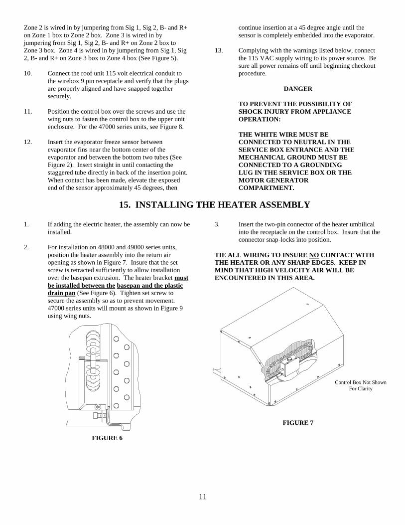
15. INSTALLING THE HEATER ASSEMBLY
1. If adding the electric heater, the assembly can now be
installed.
2. For installation on 48000 and 49000 series units,
position the heater assembly into the return air
opening as shown in Figure 7. Insure that the set
screw is retracted sufficiently to allow installation
over the basepan extrusion. The heater bracket must
be installed between the basepan and the plastic
drain pan (See Figure 6). Tighten set screw to
secure the assembly so as to prevent movement.
47000 series units will mount as shown in Figure 9
using wing nuts.
FIGURE 6
3. Insert the two-pin connector of the heater umbilical
into the receptacle on the control box. Insure that the
connector snap-locks into position.
TIE ALL WIRING TO INSURE NO CONTACT WITH
THE HEATER OR ANY SHARP EDGES. KEEP IN
MIND THAT HIGH VELOCITY AIR WILL BE
ENCOUNTERED IN THIS AREA.
FIGURE 7
Control Box Not Shown
For Clarity

12
FIGURE 8 FIGURE 9
16. INSTALL AIR GRILLE ASSEMBLY
1. Raise the chute/supply air plate to the mount frame
and ensure the plenum duct divider is positioned
between the two ribs. Install the chute/supply air
plate to the mount frame with 4 screws provided in
the parts package (See Figure 1).
2. Temporarily remove the return air grilles and filters
from the shroud assembly.
3. Raise the shroud assembly so that is properly nests
with the chute/supply air plate and attach the shroud
assembly to the mount frame with 4 provided screws.
4. Reinstall the filters and return air grilles in the shroud
assembly.
5. Installation is now complete.
Airxcel, Inc.
RV Products Division
P.O. Box 4020
Wichita, KS 67204
Web: www.rvcomfort.com
Support: [email protected]
Sales: [email protected]
1976A657 (3-15) PP