Cohesive Networks Support Docs: VNS3 Side by Side IPsec Tunnel Guide
19
© 2016 VNS3 IPsec Side by Side Connecting two or more VNS3 Controller Instances via IPsec 2016
-
Upload
cohesive-networks -
Category
Technology
-
view
223 -
download
2
Transcript of Cohesive Networks Support Docs: VNS3 Side by Side IPsec Tunnel Guide
© 2016
VNS3 IPsec Side by SideConnecting two or more VNS3 Controller Instances via IPsec 2016
© 2016
Requirements and Restrictions
2
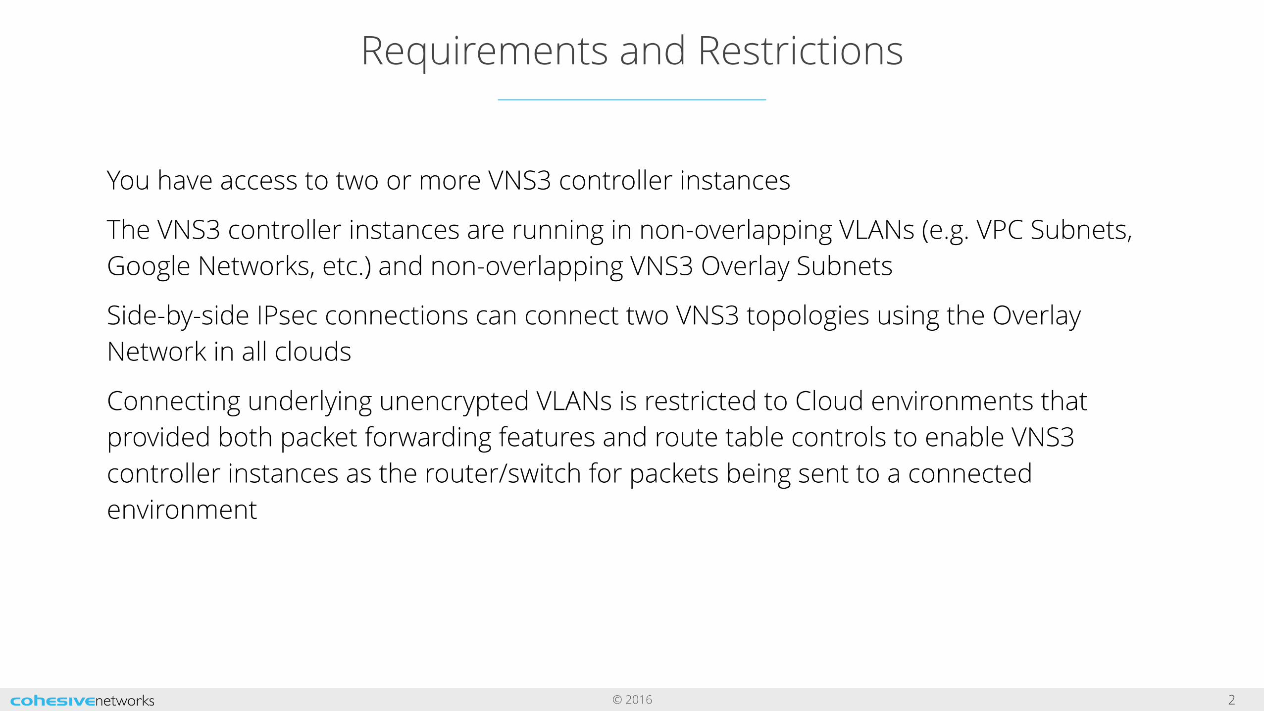
You have access to two or more VNS3 controller instances
The VNS3 controller instances are running in non-overlapping VLANs (e.g. VPC Subnets, Google Networks, etc.) and non-overlapping VNS3 Overlay Subnets
Side-by-side IPsec connections can connect two VNS3 topologies using the Overlay Network in all clouds
Connecting underlying unencrypted VLANs is restricted to Cloud environments that provided both packet forwarding features and route table controls to enable VNS3 controller instances as the router/switch for packets being sent to a connected environment
© 2016
Using NAT-Traversal Encapsulation
3

© 2016
Topology Setup
4
For the purpose of this example the IPsec tunnel connection will be made between VNS3 Controller Instance A (VNS3-A) and VNS3 Controller Instance B (VNS3-B). Note the topology name in the screenshots.
Both VNS3 controller instances are configured with a different/non-overlapping Overlay Subnet and are running in a different/non-overlapping VLAN. Our example setup is:
VNS3-AOverlay Subnet: 172.31.10.0/24VLAN: 192.168.200.0/24
VNS3-BOverlay Subnet: 172.31.11.0/24VLAN: 192.168.201.0/24
NOTE: NAT-Traversal IPsec requires UDP 500 and 4500 access between the two VNS3 Controller instances.
© 2016
Change VNS3 Local Private IP
5
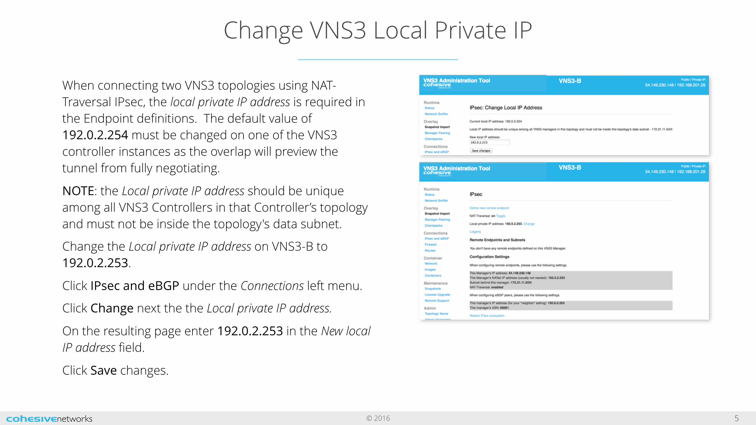
When connecting two VNS3 topologies using NAT-Traversal IPsec, the local private IP address is required in the Endpoint definitions. The default value of 192.0.2.254 must be changed on one of the VNS3 controller instances as the overlap will preview the tunnel from fully negotiating.
NOTE: the Local private IP address should be unique among all VNS3 Controllers in that Controller’s topology and must not be inside the topology's data subnet.
Change the Local private IP address on VNS3-B to 192.0.2.253.
Click IPsec and eBGP under the Connections left menu.
Click Change next the the Local private IP address.
On the resulting page enter 192.0.2.253 in the New local IP address field.
Click Save changes.
© 2016
VNS3-A: Create a New Endpoint
6
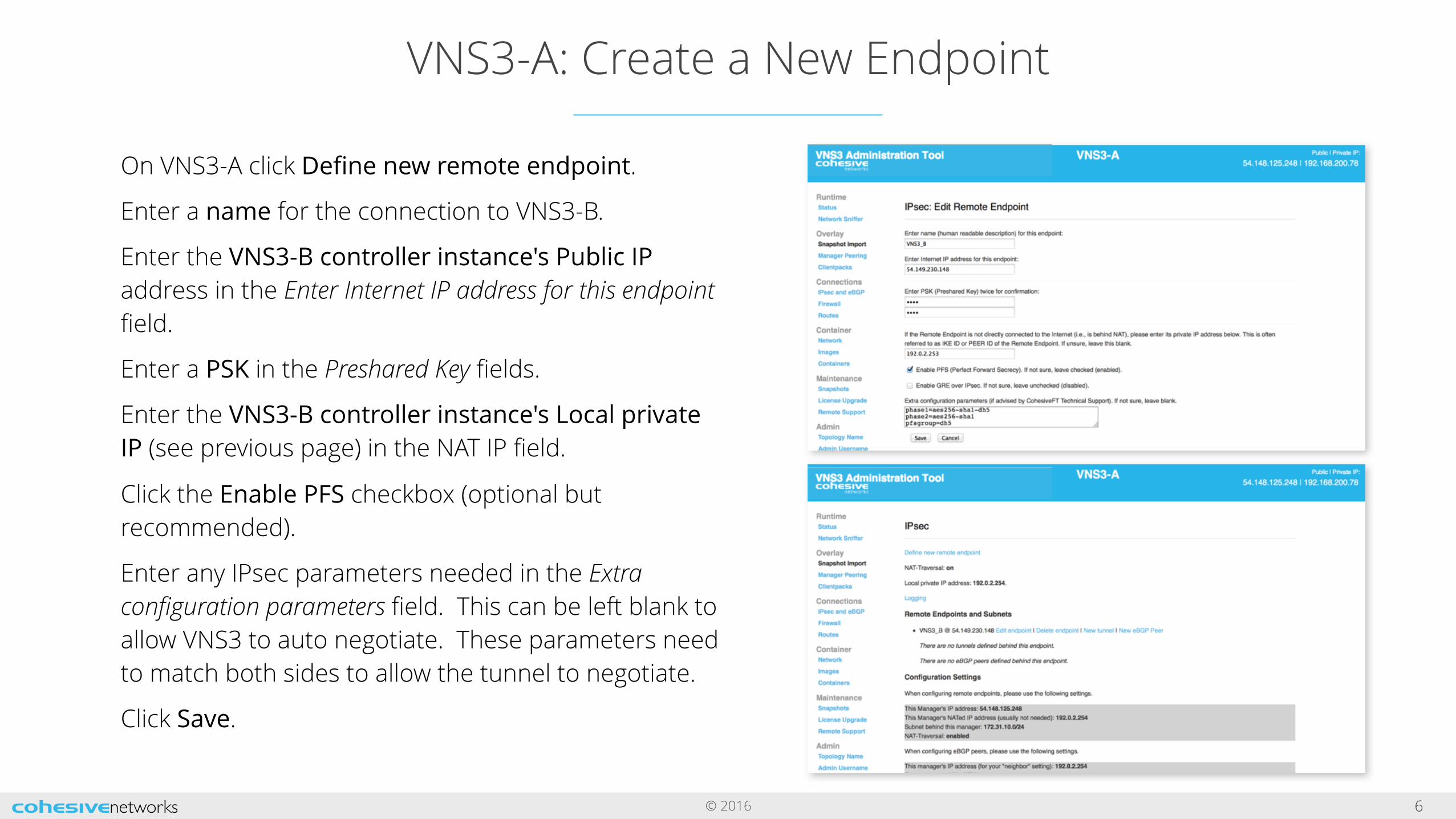
On VNS3-A click Define new remote endpoint.
Enter a name for the connection to VNS3-B.
Enter the VNS3-B controller instance's Public IP address in the Enter Internet IP address for this endpoint field.
Enter a PSK in the Preshared Key fields.
Enter the VNS3-B controller instance's Local private IP (see previous page) in the NAT IP field.
Click the Enable PFS checkbox (optional but recommended).
Enter any IPsec parameters needed in the Extra configuration parameters field. This can be left blank to allow VNS3 to auto negotiate. These parameters need to match both sides to allow the tunnel to negotiate.
Click Save.

© 2016
VNS3-A: Create a New Tunnel
7
On VNS3-A, click New tunnel next to the newly created endpoint definition.
Enter the VNS3-A Overlay Subnet in the Local subnet field.
Enter the VNS3-B Overlay Subnet in the Remote subnet field.
Enter a descriptive name in the Name field.
Click Create.
© 2016
VNS3-B: Create a New Endpoint
8
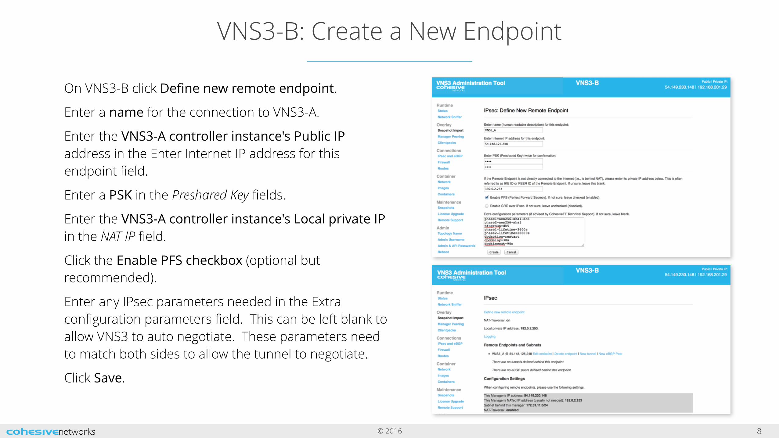
On VNS3-B click Define new remote endpoint.
Enter a name for the connection to VNS3-A.
Enter the VNS3-A controller instance's Public IP address in the Enter Internet IP address for this endpoint field.
Enter a PSK in the Preshared Key fields.
Enter the VNS3-A controller instance's Local private IP in the NAT IP field.
Click the Enable PFS checkbox (optional but recommended).
Enter any IPsec parameters needed in the Extra configuration parameters field. This can be left blank to allow VNS3 to auto negotiate. These parameters need to match both sides to allow the tunnel to negotiate.
Click Save.
© 2016
VNS3-B: Create a New Tunnel
9
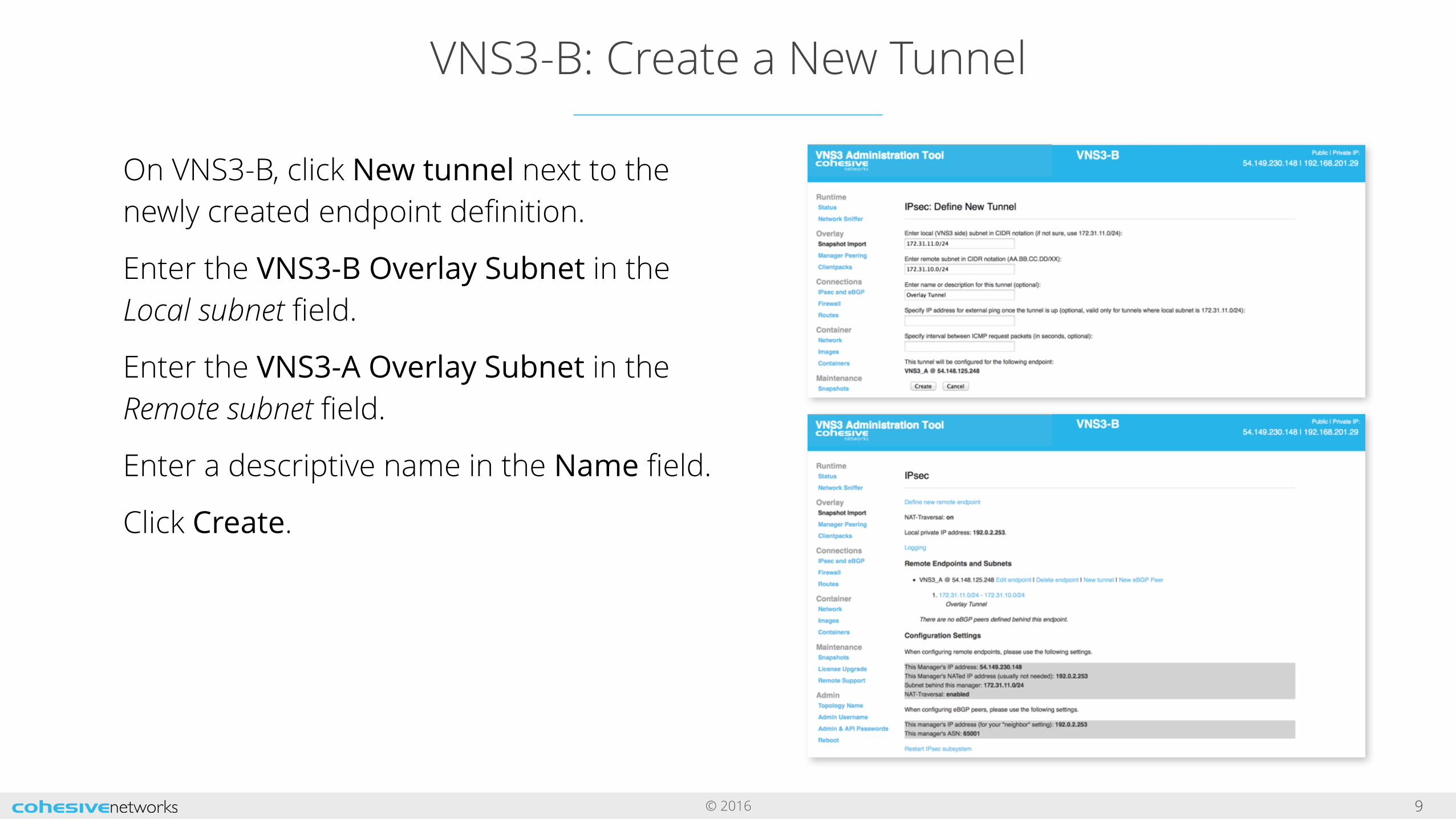
On VNS3-B, click New tunnel next to the newly created endpoint definition.
Enter the VNS3-B Overlay Subnet in the Local subnet field.
Enter the VNS3-A Overlay Subnet in the Remote subnet field.
Enter a descriptive name in the Name field.
Click Create.
© 2016
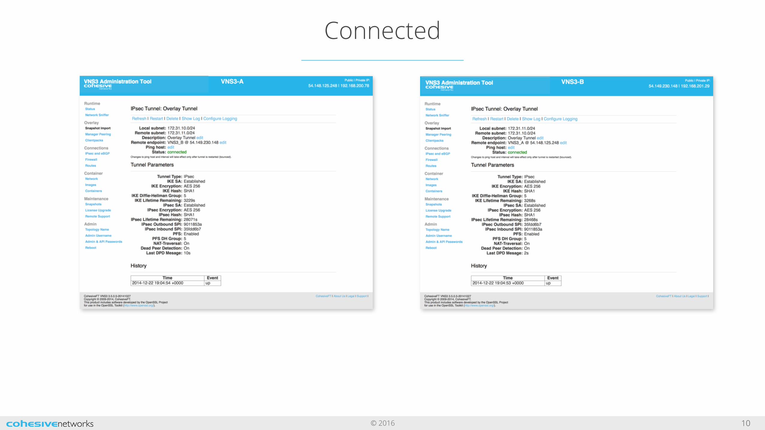
Connected
10
© 2016
Using Native IPsec
11
© 2016
Topology Setup
12
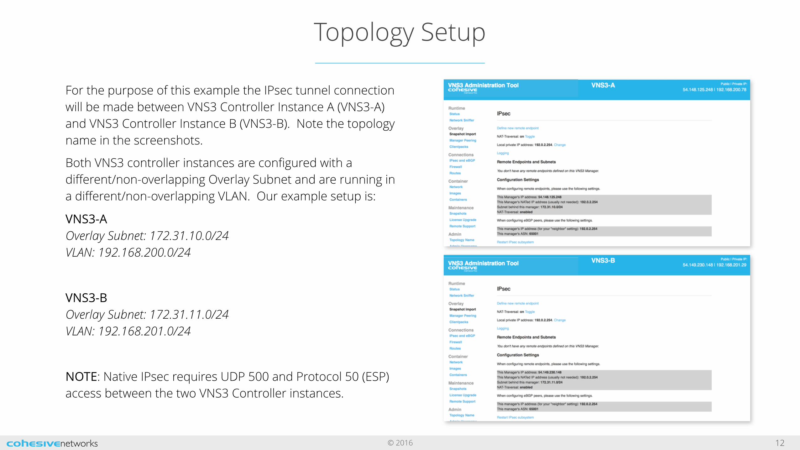
For the purpose of this example the IPsec tunnel connection will be made between VNS3 Controller Instance A (VNS3-A) and VNS3 Controller Instance B (VNS3-B). Note the topology name in the screenshots.
Both VNS3 controller instances are configured with a different/non-overlapping Overlay Subnet and are running in a different/non-overlapping VLAN. Our example setup is:
VNS3-AOverlay Subnet: 172.31.10.0/24VLAN: 192.168.200.0/24
VNS3-BOverlay Subnet: 172.31.11.0/24VLAN: 192.168.201.0/24
NOTE: Native IPsec requires UDP 500 and Protocol 50 (ESP) access between the two VNS3 Controller instances.
© 2016
Change VNS3 Local Private IP
13
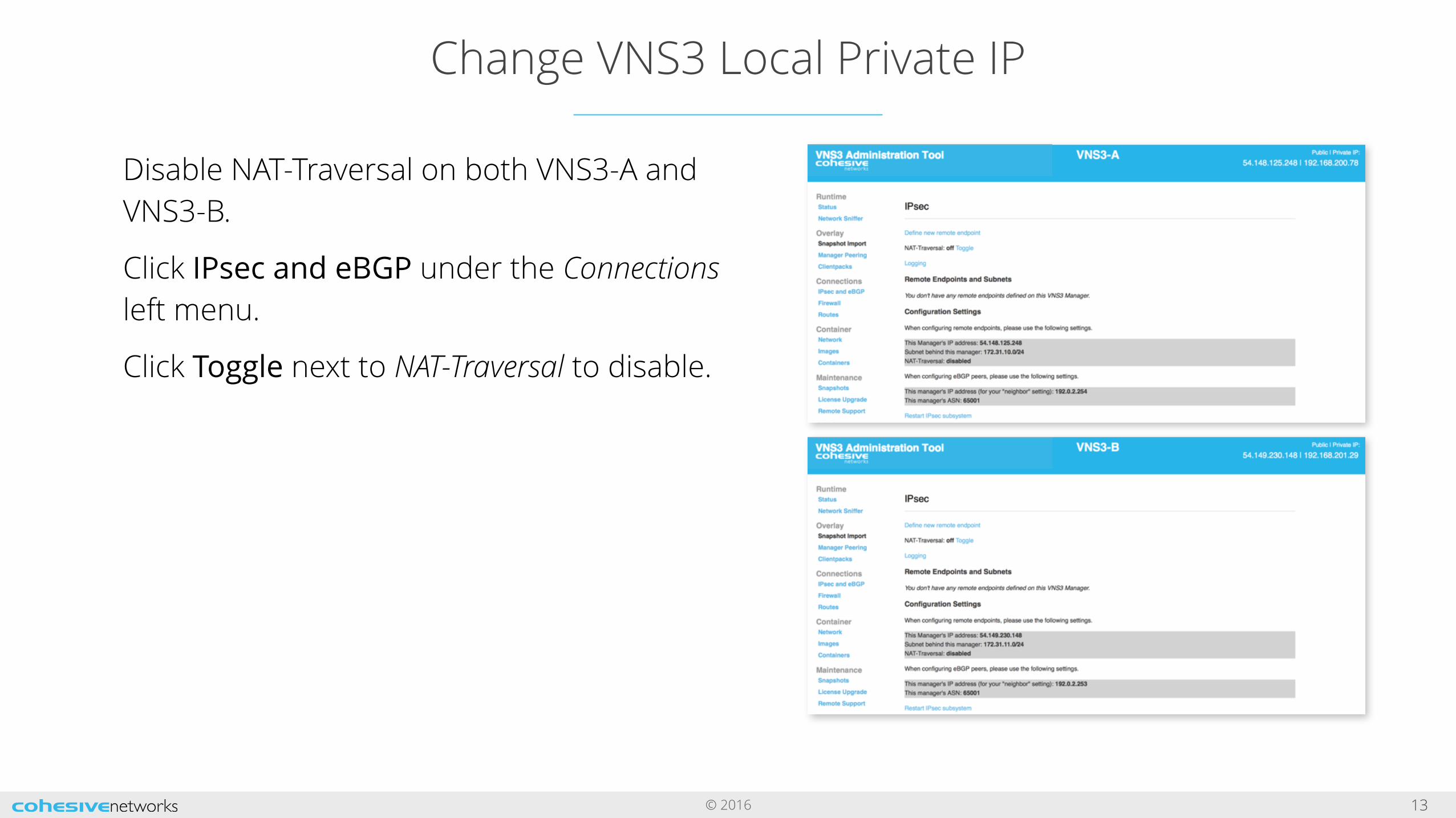
Disable NAT-Traversal on both VNS3-A and VNS3-B.
Click IPsec and eBGP under the Connections left menu.
Click Toggle next to NAT-Traversal to disable.
© 2016
VNS3-A: Create a New Endpoint
14
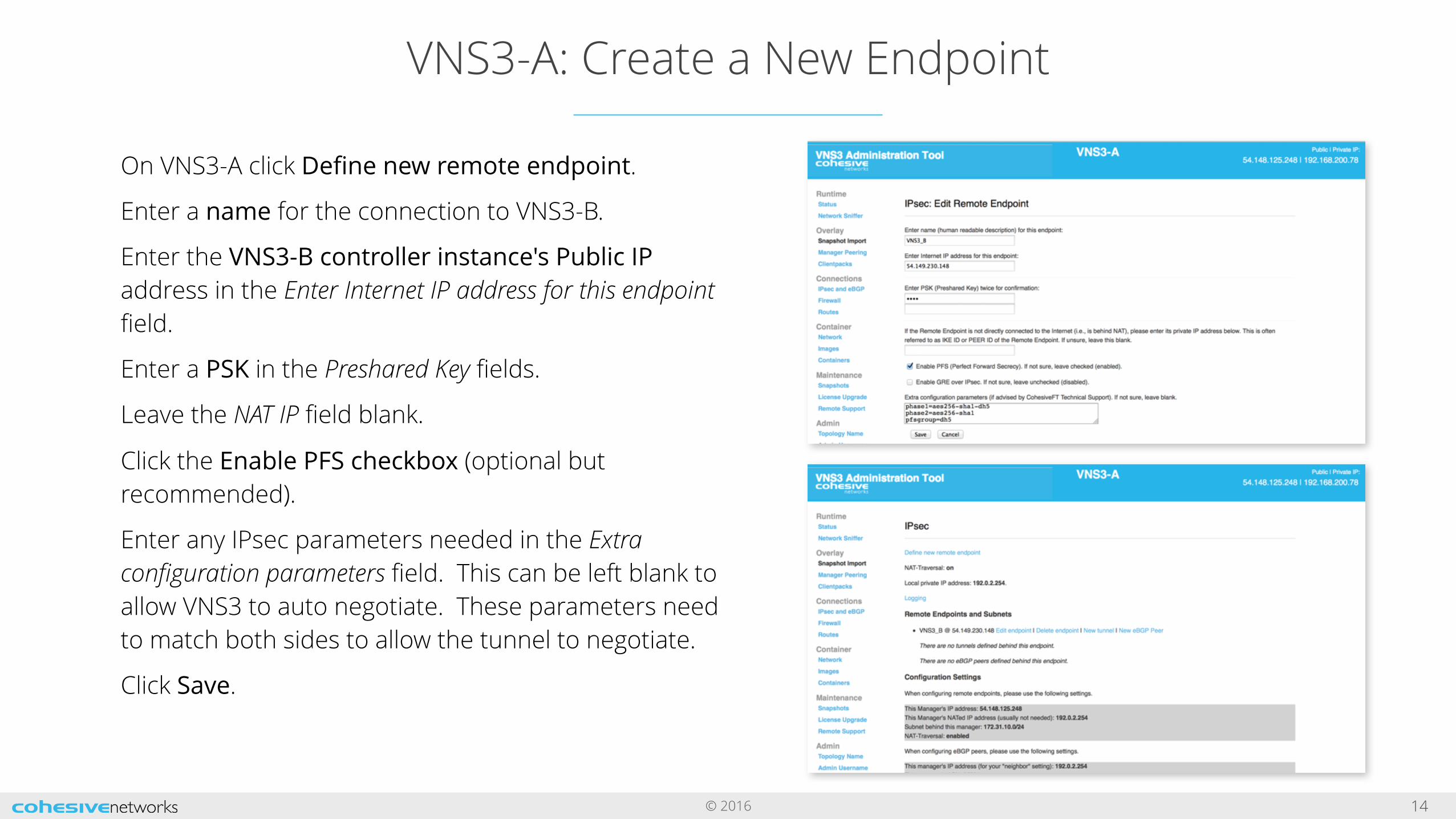
On VNS3-A click Define new remote endpoint.
Enter a name for the connection to VNS3-B.
Enter the VNS3-B controller instance's Public IP address in the Enter Internet IP address for this endpoint field.
Enter a PSK in the Preshared Key fields.
Leave the NAT IP field blank.
Click the Enable PFS checkbox (optional but recommended).
Enter any IPsec parameters needed in the Extra configuration parameters field. This can be left blank to allow VNS3 to auto negotiate. These parameters need to match both sides to allow the tunnel to negotiate.
Click Save.
© 2016
VNS3-A: Create a New Tunnel
15
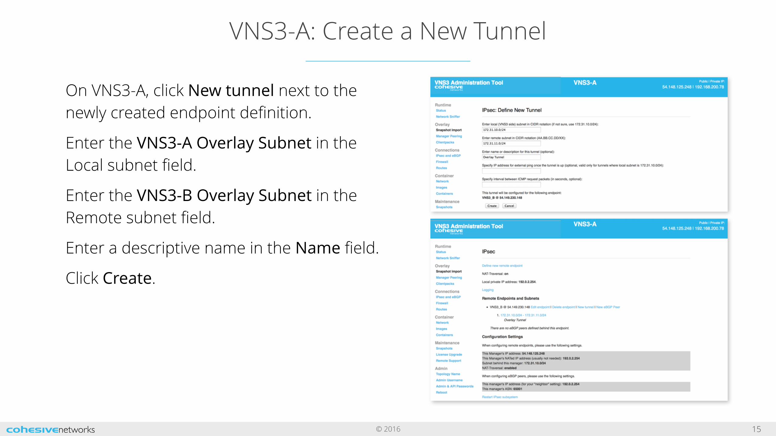
On VNS3-A, click New tunnel next to the newly created endpoint definition.
Enter the VNS3-A Overlay Subnet in the Local subnet field.
Enter the VNS3-B Overlay Subnet in the Remote subnet field.
Enter a descriptive name in the Name field.
Click Create.
© 2016
VNS3-B: Create a New Endpoint
16
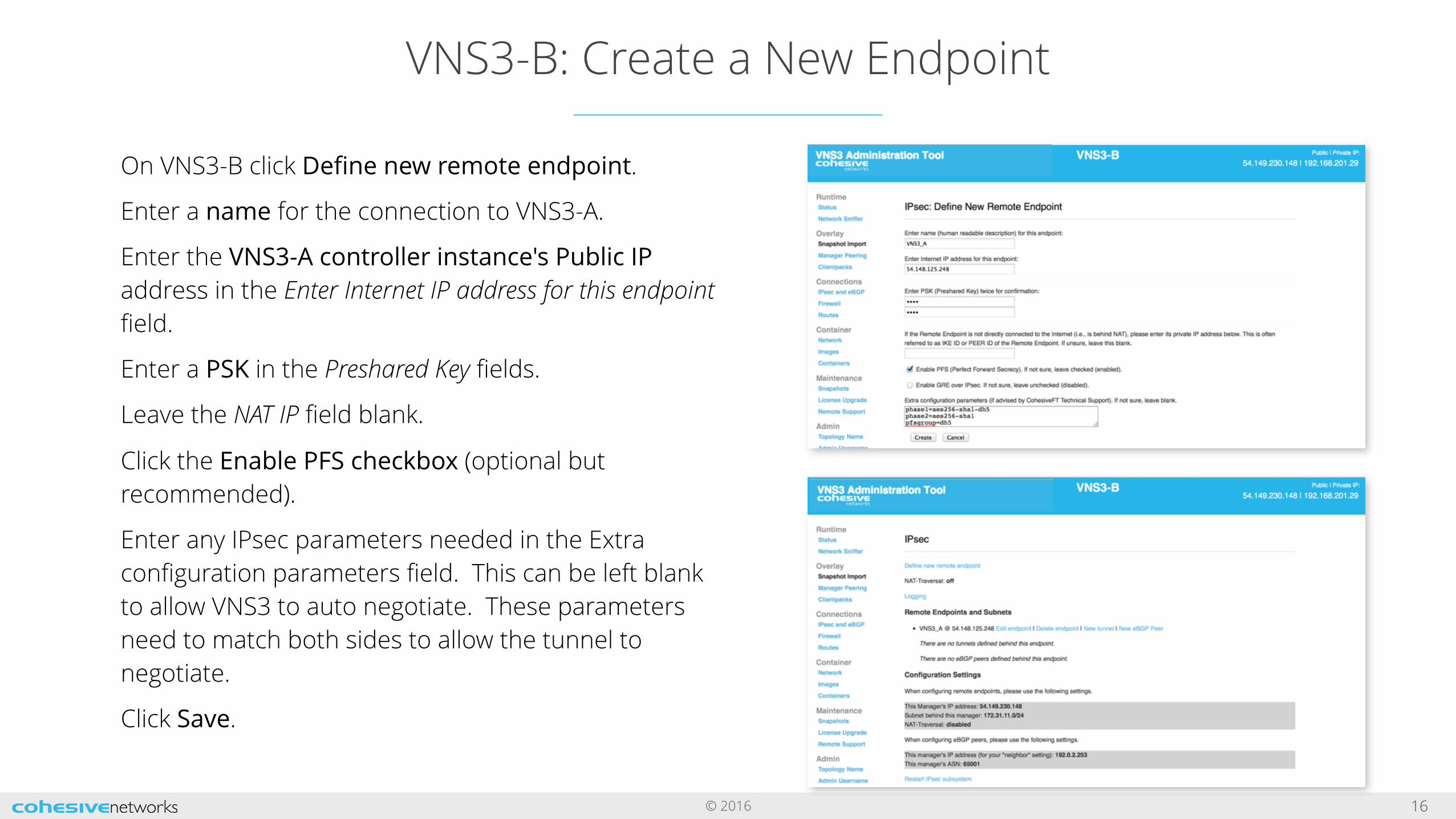
On VNS3-B click Define new remote endpoint.
Enter a name for the connection to VNS3-A.
Enter the VNS3-A controller instance's Public IP address in the Enter Internet IP address for this endpoint field.
Enter a PSK in the Preshared Key fields.
Leave the NAT IP field blank.
Click the Enable PFS checkbox (optional but recommended).
Enter any IPsec parameters needed in the Extra configuration parameters field. This can be left blank to allow VNS3 to auto negotiate. These parameters need to match both sides to allow the tunnel to negotiate.
Click Save.

© 2016
VNS3-B: Create a New Tunnel
17
On VNS3-B, click New tunnel next to the newly created endpoint definition.
Enter the VNS3-B Overlay Subnet in the Local subnet field.
Enter the VNS3-A Overlay Subnet in the Remote subnet field.
Enter a descriptive name in the Name field.
Click Create.
© 2016
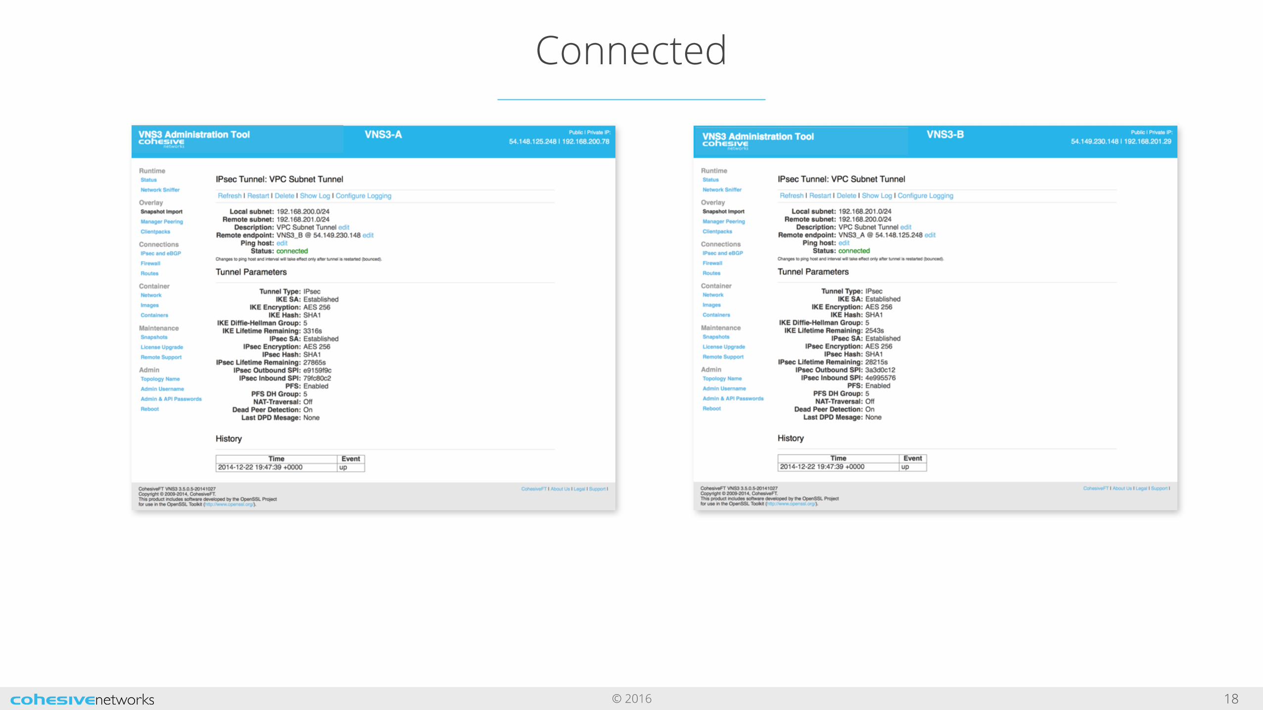
Connected
18
© 2016
VNS3 Document Links
19
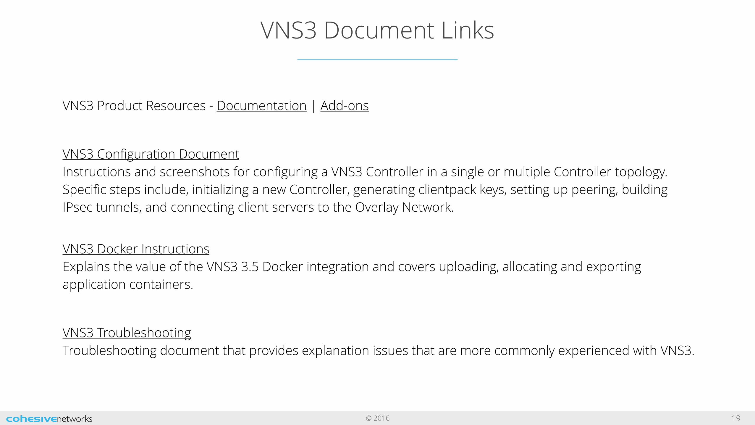
VNS3 Product Resources - Documentation | Add-ons
VNS3 Configuration Document Instructions and screenshots for configuring a VNS3 Controller in a single or multiple Controller topology. Specific steps include, initializing a new Controller, generating clientpack keys, setting up peering, building IPsec tunnels, and connecting client servers to the Overlay Network.
VNS3 Docker InstructionsExplains the value of the VNS3 3.5 Docker integration and covers uploading, allocating and exporting application containers.
VNS3 Troubleshooting Troubleshooting document that provides explanation issues that are more commonly experienced with VNS3.