Design of Efficient Cryptographically Robust Substitution ...
VNS3 IPsec Configuration VNS3 to Fortigate FortiOS 5.4.1
© 2018
Site-to-Site IPsec Tunnel
2
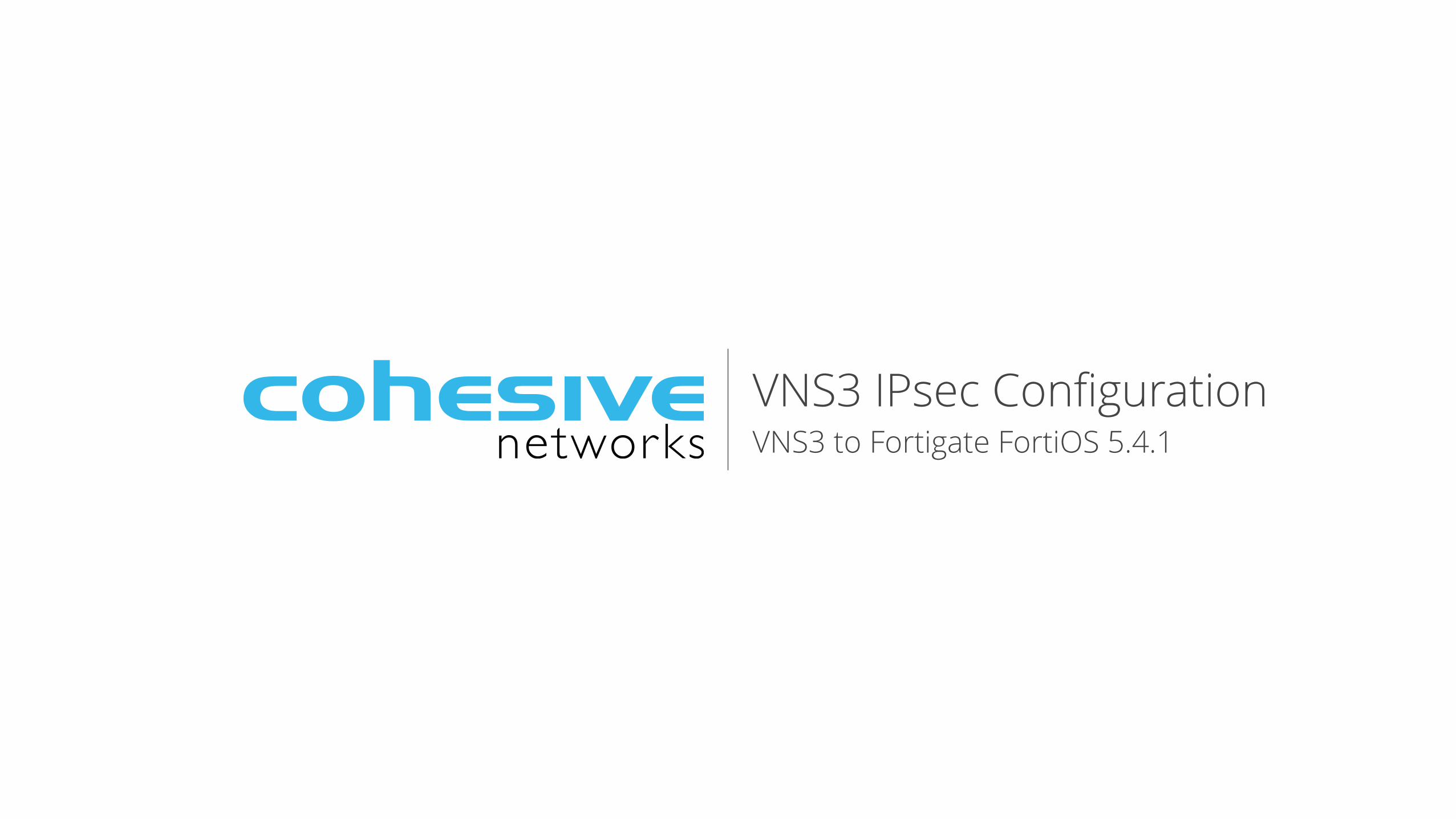
IPsec protocol allows you to securely connect two sites together over the public internet using cryptographically secured services. IPsec ensure private and secure communication between two devices. This type of VPN has many use-cases. We will focus on the Site-to-Site or LAN-to-LAN setup most often used with VNS3 to build Hybrid Clouds.
Many network hardware devices support IPsec tunneling functionality. Check your device's data sheet to see if it is compatible with VNS3. The requirements are:
• Policy-based VPN - encapsulates traffic between two sites as defined by a specific policy or ACL. This is used instead of a Route-based VPN that encapsulates traffic based on routes on both sides which can make it easier to administer but downgrades the security.
• Encapsulating Security Packet (ESP) wire level protocol - encrypting and authenticating of the data flowing over the tunnel. This is used instead of Authenication Header (AH) which only authenticates.
• Tunnel Mode - encapsulates the entire IP packet for communication over untrusted networks. This is used instead of Transport mode that only encapsulates the IP payload.
• Internet Key Exchange (IKE) v1 or v2 - protocol used to setup the shared security associations (SA) for the IPsec tunnel. This is used instead of manual key exchange.
• Main Mode - used to setup the IPsec tunnel SAs using IKE. This is used instead of Aggressive mode that requires fewer messages to establish the SA but does so in a less secured manner.
• Preshared Key (PSK) - used for authentication between two connecting parties. This is used instead of certificates. A diagram of the typical secure hybrid cloud setup using VNS3 is provided on the right. The IPsec tunnel provides secure and encrypted connectivity between the office subnet (192.169.3.0/24) and the VNS3 Overlay Network (172.31.1.0/24).
This guide will provide steps to setup the Fortigate side of the IPsec configuration.
The most important thing in any IPsec configuration is to make sure all settings match on both devices that are going to connect to each other. Mismatches are the primary cause for tunnel failure or instability.
Public Cloud
Overlay Network Subnet: 172.31.1.0/24
Cloud Server Overlay IP: 172.31.1.1
Server B LAN IP: 192.168.3.100
Server A LAN IP: 192.168.3.50
Customer Remote Office Remote subnet: 192.168.3.0/24
VNS3 public IP: 184.73.174.250 overlay IP: 172.31.1.250
Firewall / IPsec Fortigate 60D
Active IPsec tunnel 192.168.3.0/24 - 172.31.1.0/24
© 2018
Step 1 - Enable Policy-based VPN
3
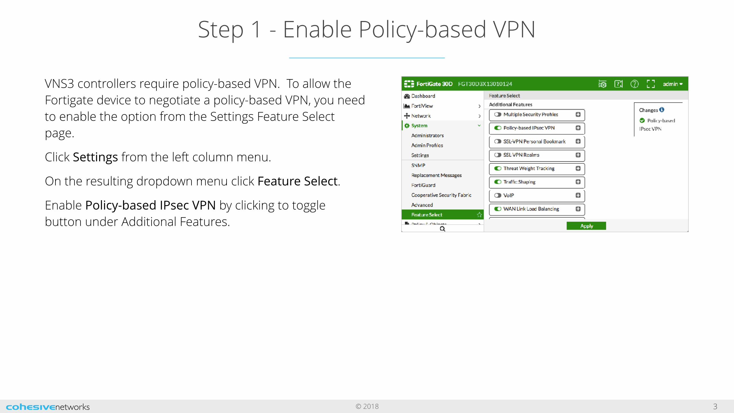
VNS3 controllers require policy-based VPN. To allow the Fortigate device to negotiate a policy-based VPN, you need to enable the option from the Settings Feature Select page.
Click Settings from the left column menu.
On the resulting dropdown menu click Feature Select.
Enable Policy-based IPsec VPN by clicking to toggle button under Additional Features.
© 2018
Step 2 - Create Address Objects
4
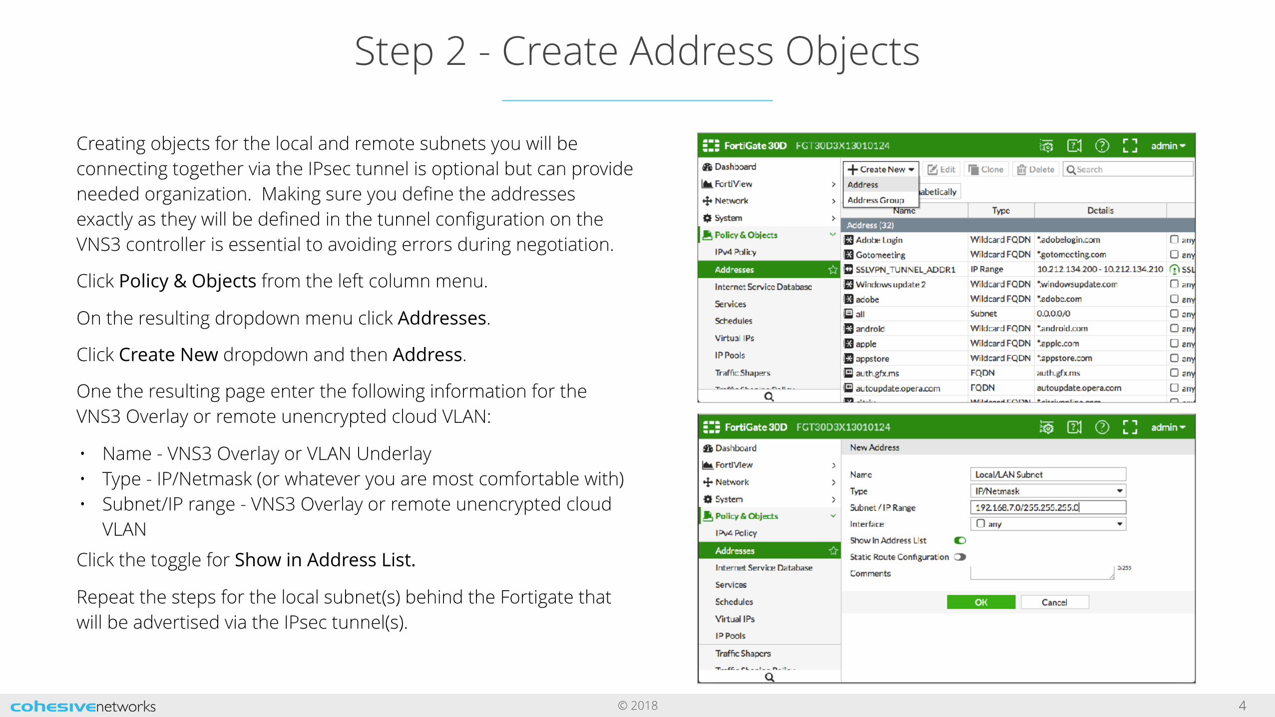
Creating objects for the local and remote subnets you will be connecting together via the IPsec tunnel is optional but can provide needed organization. Making sure you define the addresses exactly as they will be defined in the tunnel configuration on the VNS3 controller is essential to avoiding errors during negotiation.
Click Policy & Objects from the left column menu.
On the resulting dropdown menu click Addresses.
Click Create New dropdown and then Address.
One the resulting page enter the following information for the VNS3 Overlay or remote unencrypted cloud VLAN:
• Name - VNS3 Overlay or VLAN Underlay • Type - IP/Netmask (or whatever you are most comfortable with) • Subnet/IP range - VNS3 Overlay or remote unencrypted cloud
VLAN
Click the toggle for Show in Address List.
Repeat the steps for the local subnet(s) behind the Fortigate that will be advertised via the IPsec tunnel(s).
© 2018
Step 3 - Create IPsec VPN
5
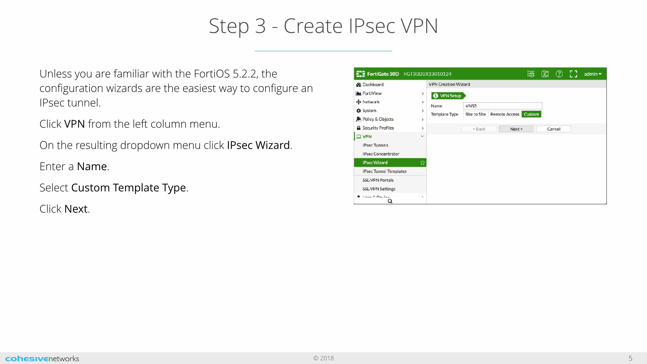
Unless you are familiar with the FortiOS 5.2.2, the configuration wizards are the easiest way to configure an IPsec tunnel.
Click VPN from the left column menu.
On the resulting dropdown menu click IPsec Wizard.
Enter a Name.
Select Custom Template Type.
Click Next.
© 2018
Step 3 continued - IPsec Endpoint Configuration
6
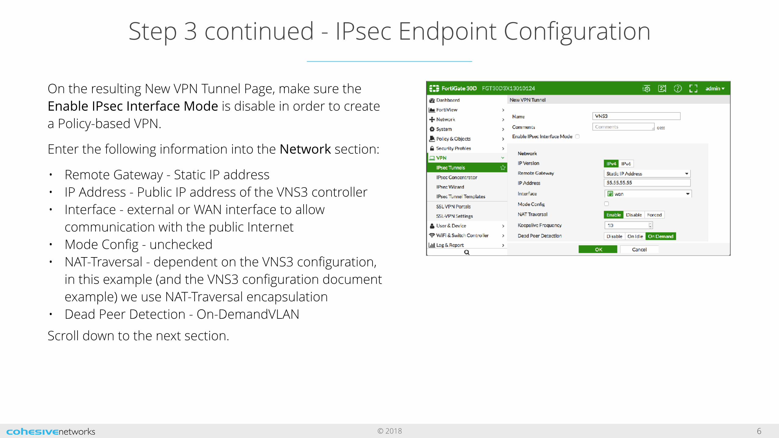
On the resulting New VPN Tunnel Page, make sure the Enable IPsec Interface Mode is disable in order to create a Policy-based VPN.
Enter the following information into the Network section:
• Remote Gateway - Static IP address • IP Address - Public IP address of the VNS3 controller • Interface - external or WAN interface to allow
communication with the public Internet • Mode Config - unchecked • NAT-Traversal - dependent on the VNS3 configuration,
in this example (and the VNS3 configuration document example) we use NAT-Traversal encapsulation
• Dead Peer Detection - On-DemandVLAN
Scroll down to the next section.
© 2018
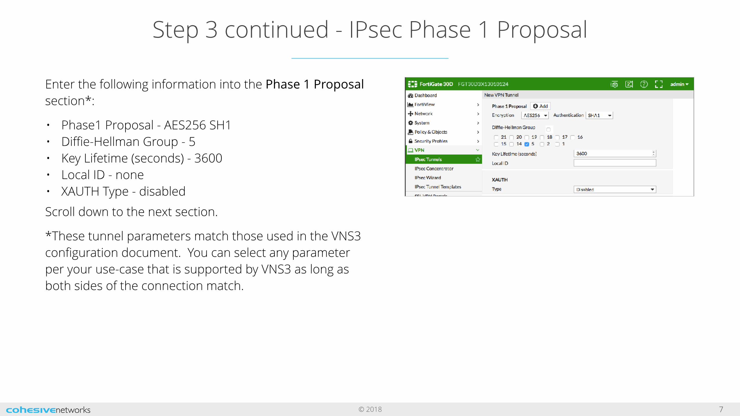
Step 3 continued - IPsec Phase 1 Proposal
7
Enter the following information into the Phase 1 Proposal section*:
• Phase1 Proposal - AES256 SH1 • Diffie-Hellman Group - 5 • Key Lifetime (seconds) - 3600 • Local ID - none • XAUTH Type - disabled
Scroll down to the next section.
*These tunnel parameters match those used in the VNS3 configuration document. You can select any parameter per your use-case that is supported by VNS3 as long as both sides of the connection match.
© 2018
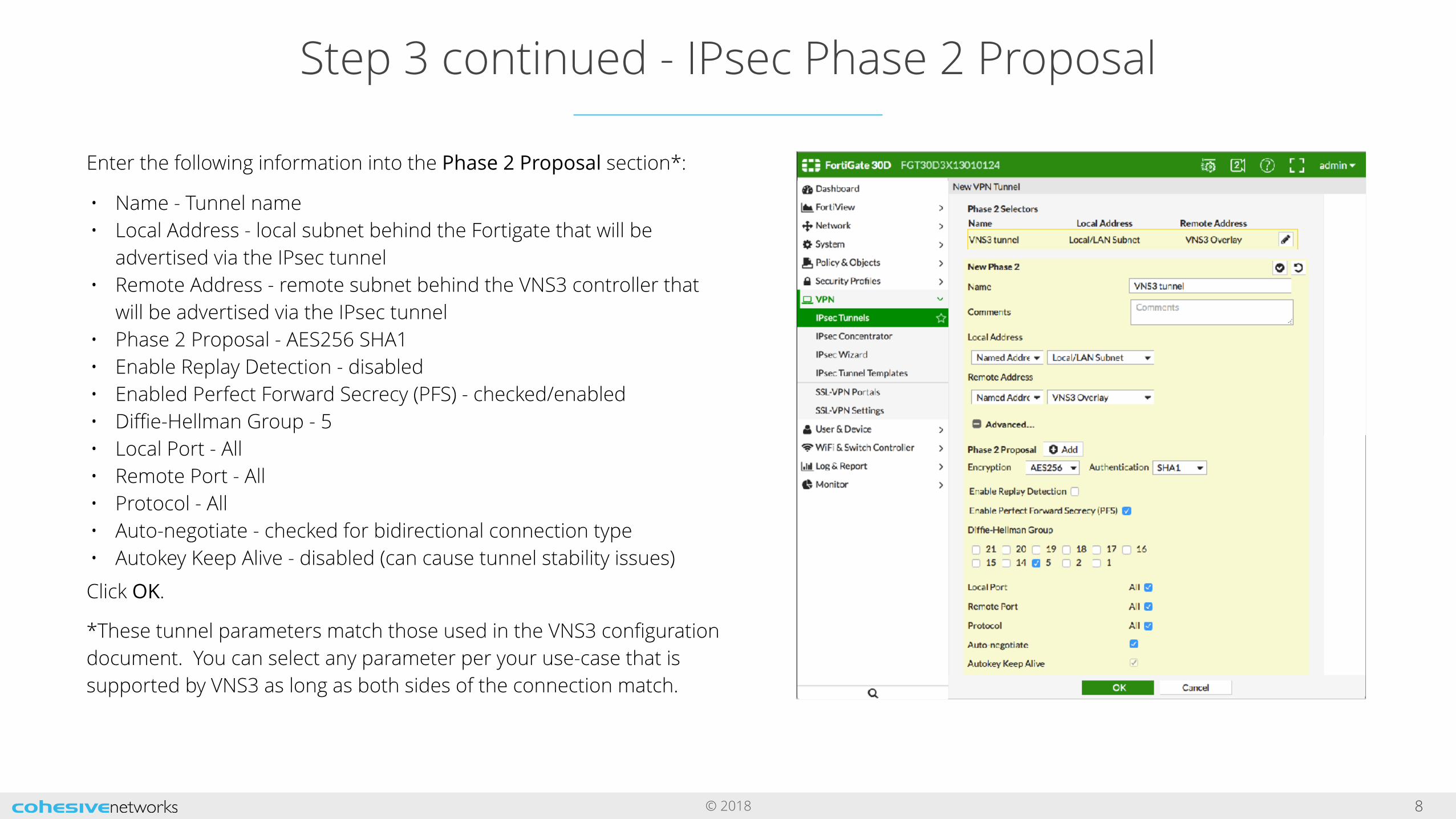
Step 3 continued - IPsec Phase 2 Proposal
8
Enter the following information into the Phase 2 Proposal section*:
• Name - Tunnel name • Local Address - local subnet behind the Fortigate that will be
advertised via the IPsec tunnel • Remote Address - remote subnet behind the VNS3 controller that
will be advertised via the IPsec tunnel • Phase 2 Proposal - AES256 SHA1 • Enable Replay Detection - disabled • Enabled Perfect Forward Secrecy (PFS) - checked/enabled • Diffie-Hellman Group - 5 • Local Port - All • Remote Port - All • Protocol - All • Auto-negotiate - checked for bidirectional connection type • Autokey Keep Alive - disabled (can cause tunnel stability issues)
Click OK.
*These tunnel parameters match those used in the VNS3 configuration document. You can select any parameter per your use-case that is supported by VNS3 as long as both sides of the connection match.
© 2018
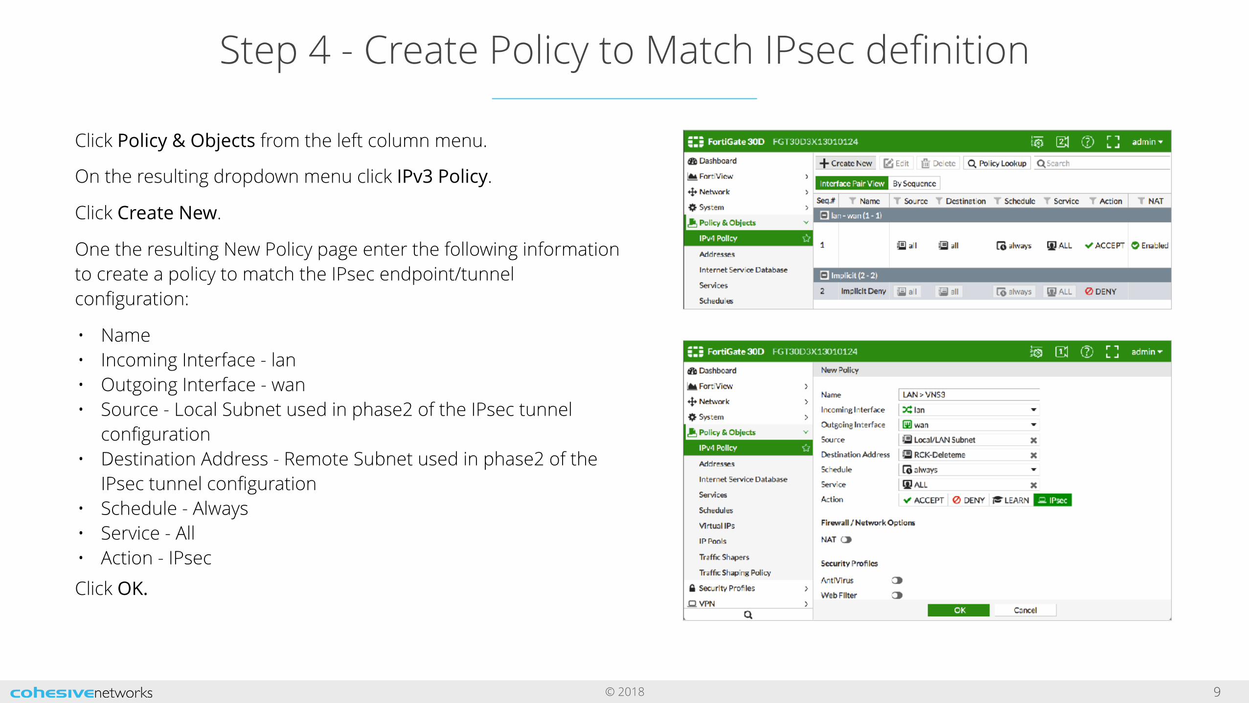
Step 4 - Create Policy to Match IPsec definition
9
Click Policy & Objects from the left column menu.
On the resulting dropdown menu click IPv3 Policy.
Click Create New.
One the resulting New Policy page enter the following information to create a policy to match the IPsec endpoint/tunnel configuration:
• Name • Incoming Interface - lan • Outgoing Interface - wan • Source - Local Subnet used in phase2 of the IPsec tunnel
configuration • Destination Address - Remote Subnet used in phase2 of the
IPsec tunnel configuration • Schedule - Always • Service - All • Action - IPsec
Click OK.
© 2018
VNS3 Document Links
10
VNS3 Product Resources - Documentation | Add-ons
VNS3 Configuration Instructions (Free & Lite Editions | BYOL)Instructions and screenshots for configuring a VNS3 Controller in a single or multiple Controller topology. Specific steps include, initializing a new Controller, generating clientpack keys, setting up peering, building IPsec tunnels, and connecting client servers to the Overlay Network.
VNS3 Administration DocumentCovers the administration and operation of a configured VNS3 Controller. Additional detail is provided around the VNS3 Firewall, all administration menu items, upgrade licenses, other routes and SNMP traps.
VNS3 TroubleshootingTroubleshooting document that provides explanation issues that are more commonly experienced with VNS3.