Coherent Multiresolution Isosurface Ray Tracingknolla/cohoctiso.pdfCoherent Multiresolution...
14
The Visual Computer manuscript No. (will be inserted by the editor) Aaron M. Knoll · Ingo Wald · Charles D. Hansen Coherent Multiresolution Isosurface Ray Tracing the date of receipt and acceptance should be inserted later Abstract We implement and evaluate a fast ray tracing method for rendering large structured volumes. Input data is losslessly compressed into an octree, enabling residency in CPU main memory. We cast packets of coherent rays through a min/max acceleration structure within the octree, employing a slice-based technique to amortize the higher cost of compressed data access. By employing a multires- olution level of detail (LOD) scheme in conjunction with packets, coherent ray tracing can efficiently render inher- ently incoherent scenes of complex data. We achieve higher performance with lesser footprint than previous isosurface ray tracers, and deliver large frame buffers, smooth gradient normals and shadows at relatively lesser cost. In this con- text, we weigh the strengths of coherent ray tracing against those of the conventional single-ray approach, and present a system that visualizes large volumes at full data resolution on commodity computers. Keywords ray tracing · isosurfaces · volume data · compression · level of detail 1 Introduction Interactive rendering of large volumes is an ongoing prob- lem in visualization. Adaptive isosurface extraction tech- niques are CPU-bound, and render a piecewise linear mesh that locally differs from the implicit interpolating surface on the source data. GPU direct volume rendering (DVR) deliv- ers consistently real-time frame rates for moderate-size data; but GPU memory imposes a limit on the volume size. Al- though large data can be accessed asynchronously through out-of-core methods and progressive rendering, rasterization algorithms nonetheless have object-order complexity, which breaks down for sufficiently large data. Given a limited number of slices sampling a high-resolution volume, GPU DVR methods have difficulty rendering a precise surface, which is often desirable in scientific and medical analysis. Scientific Computing and Imaging Institute, University of Utah, Salt Lake City, Utah 84112, Tel.: (801)585-1867 Fax: (801)585-6513 E-mail: : {knolla|hansen|wald}@sci.utah.edu Isosurface ray tracing of large volume data overcomes many of these issues. As it is not limited to polygonal ge- ometry, it can directly render implicit surface patches as base primitives, and render exact piecewise-smooth isosur- faces in this manner. More significantly, ray tracing scales well to large data, particularly when scene complexity is high relative to the number of rays that must be cast to fill a frame. Although ray tracing is increasingly feasible on the GPU, rendering on the CPU allows for direct access to expandable mainboard memory, and greater control over hi- erarchical data structures than with current GPU hardware. This flexibility enables use of an adaptive-resolution octree, which we can use as both a natively compressed data format and an acceleration structure for rendering. Previous work ray-traced large octree volumes interactively, but required substantial workstation hardware [13]. In this paper, we op- timize isosurface ray tracing with a coherent octree traversal technique, then employ a multiresolution level of detail (LOD) scheme to ensure coherence and hence performance. The resulting system allows for faster and improved-quality rendering on modest CPU hardware, and retains overall scal- ability to large data for which single-ray tracing methods have proven effective. Our paper is organized as follows: the next section reviews related work; Section 3 discusses mo- tivation for the proposed system, and a technical overview. Section 4 illustrates octree volume construction. Section 5 details the coherent octree traversal algorithm and related optimizations for large volume data. Section 6 discusses the traversal-time multiresolution scheme. Section 7 covers shading modalities; and Section 8 analyzes our results. 2 Related Work Mesh Extraction and Direct Volume Rendering The conventional method for isosurface rendering has been extraction via marching cubes [20] or some variant; paired with rasterization of the resulting mesh. Wilhelms and Van Gelder [31] proposed a min/max octree hierarchy that al- lowed the extraction process to only consider cells con- taining the surface. This concept has been extended with frustum and per-ray visibility culling [18,17] and multires- olution volume data [30]. Livnat & Tricoche [19] effec-
Transcript of Coherent Multiresolution Isosurface Ray Tracingknolla/cohoctiso.pdfCoherent Multiresolution...

The Visual Computer manuscript No.(will be inserted by the editor)
Aaron M. Knoll · Ingo Wald · Charles D. Hansen
Coherent Multiresolution Isosurface Ray Tracing
the date of receipt and acceptance should be inserted later
Abstract We implement and evaluate a fast ray tracingmethod for rendering large structured volumes. Input datais losslessly compressed into an octree, enabling residencyin CPU main memory. We cast packets of coherent raysthrough a min/max acceleration structure within the octree,employing a slice-based technique to amortize the highercost of compressed data access. By employing a multires-olution level of detail (LOD) scheme in conjunction withpackets, coherent ray tracing can efficiently render inher-ently incoherent scenes of complex data. We achieve higherperformance with lesser footprint than previous isosurfaceray tracers, and deliver large frame buffers, smooth gradientnormals and shadows at relatively lesser cost. In this con-text, we weigh the strengths of coherent ray tracing againstthose of the conventional single-ray approach, and present asystem that visualizes large volumes at full data resolutionon commodity computers.
Keywords ray tracing · isosurfaces · volume data ·compression · level of detail
1 Introduction
Interactive rendering of large volumes is an ongoing prob-lem in visualization. Adaptive isosurface extraction tech-niques are CPU-bound, and render a piecewise linear meshthat locally differs from the implicit interpolating surface onthe source data. GPU direct volume rendering (DVR) deliv-ers consistently real-time frame rates for moderate-size data;but GPU memory imposes a limit on the volume size. Al-though large data can be accessed asynchronously throughout-of-core methods and progressive rendering, rasterizationalgorithms nonetheless have object-order complexity, whichbreaks down for sufficiently large data. Given a limitednumber of slices sampling a high-resolution volume, GPUDVR methods have difficulty rendering a precise surface,which is often desirable in scientific and medical analysis.
Scientific Computing and Imaging Institute,University of Utah,Salt Lake City, Utah 84112,Tel.: (801)585-1867 Fax: (801)585-6513E-mail: : {knolla|hansen|wald}@sci.utah.edu
Isosurface ray tracing of large volume data overcomesmany of these issues. As it is not limited to polygonal ge-ometry, it can directly render implicit surface patches asbase primitives, and render exact piecewise-smooth isosur-faces in this manner. More significantly, ray tracing scaleswell to large data, particularly when scene complexity ishigh relative to the number of rays that must be cast to filla frame. Although ray tracing is increasingly feasible onthe GPU, rendering on the CPU allows for direct access toexpandable mainboard memory, and greater control over hi-erarchical data structures than with current GPU hardware.This flexibility enables use of an adaptive-resolution octree,which we can use as both a natively compressed data formatand an acceleration structure for rendering. Previous workray-traced large octree volumes interactively, but requiredsubstantial workstation hardware [13]. In this paper, we op-timize isosurface ray tracing with a coherent octree traversaltechnique, then employ a multiresolution level of detail(LOD) scheme to ensure coherence and hence performance.The resulting system allows for faster and improved-qualityrendering on modest CPU hardware, and retains overall scal-ability to large data for which single-ray tracing methodshave proven effective. Our paper is organized as follows: thenext section reviews related work; Section 3 discusses mo-tivation for the proposed system, and a technical overview.Section 4 illustrates octree volume construction. Section 5details the coherent octree traversal algorithm and relatedoptimizations for large volume data. Section 6 discussesthe traversal-time multiresolution scheme. Section 7 coversshading modalities; and Section 8 analyzes our results.
2 Related WorkMesh Extraction and Direct Volume RenderingThe conventional method for isosurface rendering has beenextraction via marching cubes [20] or some variant; pairedwith rasterization of the resulting mesh. Wilhelms and VanGelder [31] proposed a min/max octree hierarchy that al-lowed the extraction process to only consider cells con-taining the surface. This concept has been extended withfrustum and per-ray visibility culling [18,17] and multires-olution volume data [30]. Livnat & Tricoche [19] effec-

2
tively combined mesh extraction with point-based splattingfor efficient isosurface rendering. Direct volume rendering(DVR) [16] is a popular alternative to isosurfacing, andefficient for moderate-size data on GPU’s [3]. LaMar etal. [15] proposed a multiresolution sampling of octree tileblocks according to view-dependent criteria. Boada et al. [2]proposed a coarse octree built upon uniform sub-blocks ofthe volume, and a memory paging scheme. Large data hasbeen addressed via block-based adaptive texture schemes(e.g. Kraus & Ertl [14]), and an octree hierarchy of wavelet-compressed blocks (e.g. Guthe et al. [9]).
Volumetric Isosurface Ray TracingInteractive isosurfacing of large volumes was first realizedin a ray tracer by Parker et al. [23], using a hierarchical gridof macrocells as an acceleration structure. A single ray wastested for intersection inside a cell of eight voxel vertices,solving a cubic polynomial to find where the ray intersectsthe interpolant surface in that local cell. DeMarle et al. [5]extended this approach to clusters, allowing arbitrarily largedata to be accessed via distributed shared memory. Coher-ent ray tracing [24,26,28] combined highly-optimized co-herent traversal with SIMD primitive intersection to deliverup to two orders of magnitude increase in frame rate, al-lowing interactive ray tracing on a single processor. Marmittet al. [21] adapted the trilinear interpolant path intersectiontest to a SIMD SSE architecture. Wald et al. [27] imple-mented a coherent SIMD isosurface ray tracer employingimplicit kd-trees. This system was extended by Friedrich etal. [7] with an multiresolution volume hierarchy for efficientout-of-core progressive rendering. Knoll et al. [13] imple-mented a single-ray traversal scheme for rendering octree-compressed volume data. By employing one structure forboth the min/max acceleration tree and the voxel data itself,this system rendered large volumes given limited main mem-ory. While octree volume traversal incurred some penaltyfrom looking up compressed data within the octree, it per-formed competitively with the best-known techniques em-ploying either single rays or packets.
LOD Ray TracingLevel of detail methods have already been employed inray tracing. Igehy et al. [10] proposed ray differentials asa LOD metric for improved mipmap texture filtering. Yoonet al. [32] explored hierarchical splatting as a method ofrendering massive mesh models. Djeu et al. [6] employedray differentials in conjunction with subdivision surfaces forray tracing LOD geometry.
3 Coherent Ray Tracing of Volume Data using LOD
The primary goal of this work is to optimize ray tracing ofoctree volumes, and ideally to deliver interactivity on com-modity CPU’s. Our main vehicle for such performance gainsis coherence. The general premise is to assemble neighbor-ing rays into groups, or packets, with common characteris-tics. Then, rather than computing traversal and intersection
per ray, we perform these computations per packet. High co-herence occurs when rays in a packet behave similarly, inter-secting common nodes in the efficiency structure or commoncells in the volume. Thus, coherence depends on scene com-plexity as defined by the dataset and camera position.
Coherence via Level of DetailSuccessful coherent systems have been optimized for rela-tively small dynamic polygonal data [28,26] in which manyrays intersect common primitives. In contrast, large vol-ume data exhibit low spatial coherence, particularly fromfar-away camera positions. Isosurface ray tracing of largedata using conservative 2x2 ray packets [27] has suggestedperformance generally on par with a single-ray system [13].Coherent traversal may induce more intersection tests thana single-ray traversal; and without optimizations, actuallyperform worse than a single-ray tracer. To remedy this, weemploy a multiresolution level of detail scheme: when datais sufficiently complex to hamper coherence, we rendera coarser-resolution representation with higher coherence.The octree volume is inherently suited as a multiresolutionLOD structure; coarser-resolution voxel data can be storedin interior nodes, allowing the original data, accelerationstructure and all LOD’s to be stored for a fraction of theoriginal uncompressed data footprint. To render a coarserLOD, one simply specifies a cut of octree at a specifieddepth. The ray tracer then omits traversal and intersectionof subtrees below that depth, and instead intersects coarser,larger cells at termination depth. As more rays intersect acommon cell, coherence, and thus speedup, is achieved.OverviewAs shown in Fig. 1, our system consists of offline construc-tion of the multiresolution octree structure from the originaldata (A); followed by rendering of this octree using a thread-parallel SSE-optimized packet ray tracer (B), e.g. [27]. Thelatter distributes ray packets to worker threads (C), whichthen perform per-packet coherent traversal, SSE isosurfaceintersection, and shading in that order. Our main contribu-tions involve extending the static-resolution octree volumeto multiresolution (Section 4); devising a coherent traver-sal technique for the octree (Section 5); and leveraging the
Fig. 1 System overview.

3
traversal technique to reduce the cost of compressed dataaccess (Section 6). Ultimately, our system delivers interac-tive ray tracing on a desktop CPU while preserving imagequality, and enables shading techniques that would be ex-pensive in a conventional non-coherent octree volume raytracer. Moreover, it allows for scalable rendering of largedata that would be difficult for object-order volume render-ing on single-GPU systems.
4 Multiresolution Octree Volume Construction
An octree volume is an hierarchically compressed scalarfield. Scalar values are stored at leaf nodes. At maximumoctree depth, these correspond to the finest available dataresolution. Scalars at less than maximum depth store coarserresolutions, by factors of 8 per depth level. Interior nodesmaintain pointers from parents to children. In our multireso-lution LOD application, they also contain coarser-resolutionrepresentations of each of their children.
Fig. 2 Octree volume format illustrated, showing examples of an in-terior node, a cap node, and scalar leaves.
4.1 Construction AlgorithmVolume data can be natively computed and stored in theadaptive octree format. Alternately, the octree can be builtfrom a scalar field in a 3D array. Such a construction is de-tailed by Knoll et al. [13]; this paper only discusses exten-sions to the construction technique that allow for multires-olution. In brief, construction is a bottom-up procedure inwhich identical or similar voxels are merged together intoa single voxel within a parent node. Voxels are logicallyleaves of the octree. However, rather than store each voxelin a separate memory structure, we store every voxel withinits immediate parent. This yields two distinct structures: capnodes consisting of eight voxels at the finest resolution; andinterior nodes consisting of pointers to other nodes, whichcan optionally be single scalar leaf voxels of a coarser res-olution. As shown in Fig. 2, A scalar leaf is not a sepa-rate structure, but a value embedded inside its parent inte-rior node. Similarly, cap nodes are not leaves themselves butcontain eight scalars at the maximal depth of the octree.
Extension to multiresolutionIn multiresolution octree volume construction, coarser-resolution consolidated voxels are always computed andstored in interior nodes, regardless of whether or not they
are leaves. Theoretically, a static-resolution octree volumecould use a single array to contain either a pointer to a childsubtree or a coarser-resolution scalar leaf. In practice how-ever, the memory savings of this approach were too small tojustify the added computation. Multiresolution octree vol-umes are thus constructed exactly as in the static-resolutionimplementation [13]: nodes store eight-value arrays forchild pointers and scalar leaves. The only difference is thatmultiresolution rendering actually uses non-leaf scalar data.
Min/Max tree computationThe only significant difference between multiresolution andstatic-resolution construction lies in computing the min/maxtree. Static-resolution data requires the min/max pair of agiven voxel to reflect the minimum and maximum of eightscalar vertices constituting the cell that maps to this voxel(Fig. 3). We do not store a min/max pair for each finest-level voxel due to the prohibitive 3x footprint. Instead, wecompute them for the immediate parents of the finest voxels(cap nodes in Fig. 2). As shown in Fig. 4 (top), each leafnode must compute the minimum and maximum of its cell,hence account for the values of neighbors in the positive Xand Y dimensions (left). This yields a min/max pair for theleaf node (right). Neighbors can potentially exist at differentdepths of the octree, as is the case for at the blue leaf node..For multiresolution data, cells may have any power-of-twowidth, and we accordingly consider forward-neighbors ateach depth of the min/max tree (Fig. 4, bottom). As a re-sult, the min/max tree for a multiresolution octree volumeis looser than that of static-resolution data. In practice, theimpact on performance is negligible for the data we test.
Fig. 3 Voxel-cell mapping. Given a scalar-centered voxel, we con-struct its dual cell by mapping the scalar to the lower-most vertex, andassigning forward-neighboring scalars to the remaining vertices.
Fig. 4 Min/max tree construction from forward neighbors.

4
5 Coherent Octree Volume Ray Tracing
Having constructed a compact octree volume with an em-bedded min/max acceleration structure, we now turn to thetask of building a coherent ray tracing system. In general, weseek to optimize for coherence as aggressively as possible,namely by implementing a vertical SSE packet architectureand a frustum-based octree traversal similar to the coherentgrid traversal of Wald et al. [28].
5.1 SSE Packet Architecture
A coherent ray tracer achieves its performance by operat-ing on groups of neighboring or similar rays in packets. Toexploit coherence during primitive intersection, we performcomputations on SIMD groups of four rays (frequently re-ferred to as packlets) and mask differing hit results as nec-essary. Performing these SIMD computations requires thatwe store ray information vertically within a packet. For ex-ample, ray directions are stored as separate arrays of X,Y,Zcomponents, as opposed to a single horizontal array of 3-vectors. These vertical arrays are 16-byte-aligned, permit-ting us to access a packlet of four rays at a time in a singleSSE register. Similarly, the packet structure stores alignedSSE arrays of hit results, such as hit position and normals.
5.2 Coherent Traversal Background
As an efficiency structure for ray tracing, the octree affordsseveral different styles of traversal. With coherent ray trac-ing, we are given the choice between depth-first traversalsimilar to a kd-tree [29] or BVH [26]; or a breadth-first co-herent grid traversal (CGT) approach [28]. We choose thelatter for several reasons. Our primitives are regular, non-overlapping cells, similar to large spherical particle data setsfor which CGT has proven effective by Gribble et al. [8].More significantly, the breadth-first nature of the CGT al-gorithm allows for a clever slice-based technique that amor-tizes voxel look-up from the octree when reconstructing thevertices of multiple cells.
Fig. 5 Coherent Grid Traversal. The CGT algorithm [28] traverses apacket of rays through a grid slice by slice along a major march axis K,iteratively incrementing slice extents by the differential of the bound-ing frustum along the non-major axis U (and a third axis V in 3D).
Coherent Grid Traversal Algorithm
The original CGT algorithm departs from single-ray gridtraversal in that it considers full slices of cells containedwithin a ray packet’s bounding frustum, as opposed tomarching across individual cells. The algorithm first deter-mines the dominant X,Y,Z axis component of the first rayin each packet. This is denoted K, and the remaining axesare denoted U and V. Then, we consider the minimum andmaximum u and v coordinates at the k = 0 slice, and notethat the increment du,dv for a single unit along the marchaxis K is constant. We store this increment in a single SSEpacked floating point unit, duv = [dumin,dvmin,dumax,dvmax].Next, we determine the first and last k slice where the packetfrustum intersects the volume. We begin at the u,v extents,euv = [umin,vmin,umax,vmax], the minimum and maximum ofenter and exit points on that slice of cells. To intersect primi-tives, we truncate these values to integers and iterate over allcells in that given U,V range. To march to the next slice, weadd the constant increment. Thus, a non-hierarchical gridmarch is accomplished with a single SIMD addition and aSIMD float-to-integer truncation. Unlike a single-ray DDAgrid algorithm [1], cells may be traversed in arbitrary U,Vorder; however the K order is invariably front to back, per-mitting early termination. The 2D analog of this algorithmis illustrated in Fig. 5.
Macrocell Hierarchical CGT
The original CGT paper [28] implemented a two-level hier-archy, with a single layer of macrocells each correspondingto 6 grid cells. For small polygonal data, this was generallysufficient. As the smallest volume we test is 3023, a morerobust hierarchy could be desirable for our application. Weextended the CGT algorithm to arbitrary number of macro-cell layers similarly to Parker et al. [22], and found that arecursive 23 macrocell hierarchy – equivalent to a full oc-tree – consistently yielded the best performance for volumeslarger than 2563. The macrocell traversal employs an arraystack structure to avoid recursive function calls: this storesthe u,v slice and increment for all macrocell levels, the cur-rent slice within the current macrocell level, and the nextslice at which to return to parent macrocell traversal. Whenall rays in a packet have intersected or the packet exits theroot macrocell level, traversal terminates. The approach isthat of a recursive grid sharing common coordinate spaceon the given volume dimensions, in which each macrocellblock is a multiple M of its children. Thus, child coordi-nates are always an M-multiple of parent macrocell coor-dinates. Child macrocells, or the volume cells themselves,are traversed when any macrocell in a given slice is non-empty – specifically, when our desired isovalue is withinthat macrocell’s min, max range. Then, the packet frustumtraverses full slices of that macrocell level’s children. Asshown in Fig. 6, our hierarchical grid employs recursivelysuperimposed macrocell blocks, with each parent containing23 children, for alignment with the octree volume. We de-pict a 3-deep hierarchy, with blue, yellow and green extentscorresponding to macrocell layers from coarsest to finest.

5
Macrocells are only traversed when they contain our desiredisovalue, as illustrated by the “surface” at the dotted line.With an octree, macrocells are implicit; min/max pairs areretrieved from the octree nodes via hashing.
Fig. 6 Coherent Octree Traversal via Implicit Macrocells.
5.3 Implicit Macrocell Grid Traversal of Octree Volumes.
Our octree volume traversal is effectively coherent gridtraversal of an implicit macrocell hierarchy, in whichmin/max pairs are retrieved from octree interior nodes in-stead of macrocells. Rather than repeatedly multiplying gridcoordinates by the macrocell width M, octree nodes at alldepths share a common coordinate space [0,2dmax ], wheredmax is the maximum depth of the tree. Some macrocelltraversal computation can be optimized for the binary sub-division of the octree. When recursing from a parent totraversing children, the macrocell grid multiplies the k-sliceby the macrocell width M; in the octree M = 2, a bitwiseleft-shift. Computing the next macrocell slice requires asimple +2 addition.
Mapping Macrocells to Octree Nodes
Traversing implicit macrocells over an octree requires par-ticular attention, as a single coarse scalar leaf node in the oc-tree may may cover multiple finer-level implicit macrocells.Given an implicit macrocell coordinate, we seek the deepestoctree child that maps to it. We then use the min/max pairin the parent node, corresponding to that child, to performthe isovalue culling test. As lookup is costly, we store thepath from the octree root to the current node along the u,v-minimal ray of the frustum. We then use neighbor-findingas detailed in [13] to inexpensively traverse from one nodeto the next. Hierarchically recursing from a parent node to achild requires a single lookup step in the octree.
Default Slice-Based Traversal
At shallow levels of the octree, the packet frustum typicallytraverses a single common macrocell. At deeper levels, theu,v extents encompass multiple macrocells, so we mustneighbor-find numerous octree nodes. By default, macrocellCGT stops iterating over a slice when any node is non-empty, and proceeds to traverse slices of children nodes.
This ensures that traversal is performed purely based onthe packet frustum as opposed to individual rays, and pre-serves the breadth-first coherent nature of the algorithm.Unchecked, it also causes numerous unnecessary octreelookups and ray-cell intersection tests. To mitigate this, weimplement the two following optimizations.
Fig. 7 Culling empty macrocells from cap-node slices.
Culling empty cap-level macrocells. To avoid unneces-sary intersections and octree hashing, we clip the u,v slicecorresponding to the deepest-level macrocells, one levelabove actual cell primitives. To do this, we iterate over themin/max pairs corresponding to the finest available octreedepth. When traversing at maximum resolution, the deepestmacrocells correspond to cap nodes (Fig. 2). Within thisiteration, if a macrocell contains our isovalue, we computenew slice extents based on the minimum and maximumu,v coordinates. If the macrocell is empty, we omit it fromextent computation. The effect is to clamp the u,v slice sothat it more tightly encloses nodes with the desired isovalue.Fig. 7 illustrates this where we first clip slices of deepestmacrocells, corresponding to cap nodes of the octree atdepth dmax − 1. We narrow the u,v slice extents by omittingmacrocells with ranges outside our value; only the shadedcells containing our isovalue are considered.
Fig. 8 Clipping cell slices to fit active rays.
Clipping the cell-level slice to active rays. To further re-duce the number of cell primitives in a slice, we intersectindividual rays with the world-space bounding box formedby the current u,v slice. When rays have already successfully

6
hit a cell, they are “inactive” and can be safely ignored evenif they intersect the slice bounding box. As shown in Fig. 8,this enables us to considerably shrink the u,v extents beforeintersecting a K-slice of cells by simply by computing theminimum and maximum of the enter and exit hit coordinatesof active rays.
5.4 Cell Reconstruction from Cached Voxel Slices
Having clipped the primitive-level slice to as small a u,v ex-tent as possible, we are ready to perform ray-cell intersec-tion. Our ray-tracing primitive is a cell with eight scalar val-ues; one at each vertex. However, the data primitives in ouroctree volume are voxels. Using the same duality employedby min/max tree construction, we map octree voxels to thelower-most vertex of each cell (Fig. 3). Our task now is toreconstruct cells efficiently from the octree, exploiting co-herence whenever possible.
Fig. 9 Slice-based cell reconstruction algorithm.
U,V Voxel Slice Filling
In single-ray and depth-first traversals, cells are constructedindependently, given a lower-most voxel from traversal, andusing neighbor-finding to look up the remaining seven vox-els. However, adjacent cells share vertices – much neighbor-finding effort is duplicated. With our octree CGT, we caniterate over an entire slice of adjacent u,v cells, access eachvoxel once, and store the results in a 2D array buffer. Weadd 1 to the maximal u,v slice extent to account for forwardcell vertices in those directions. Then, we iterate over the uand v components of the slice, performing neighbor-findingfrom one coordinate to the next. By iterating in a scanline,the neighbor-finding algorithm need only find a common an-cestor along one axis, and is slightly cheaper. We store thevoxel results for this slice in a 2D array buffer, and look upvalues from this buffer to reconstruct four vertices of eachcell in the slice. The remaining four vertices can be recon-structed in the same fashion by filling in a second bufferfor the k+1 slice. Thus, to find the eight vertices of eachcell, rather than neighbor-find seven forward-neighbors pervoxel, we exploit our slice-based traversal to look up and
cache K-slices of voxels, amortizing and reducing the cost ofdata access. Fig. 9 illustrates filling of five successive slices,with like colors representing where cached voxels are usedto avoid repeat neighbor-finding.
Copying the Previous-Step K-Slice
In cell reconstruction, we also exploit voxel coherence alongthe K axis. For this, we note that vertices on either the front(k) or back (k+1) slice of each cell are shared from onetraversal step to the next, depending on whether the K marchdirection is positive or negative. In either case, we can copyan advancing slice buffer from the previous traversal stepinto a posterior buffer of the current traversal step (Fig. 9).We must account for the traversal offset in the minimum u,vcoordinates between the two buffers; and perform neighbor-finding for voxels not buffered from the previous step, dueeither to that offset or different maximal u,v extents.
5.5 Ray-Cell Intersection
With our cached slice buffers, we can iterate over cellprimitives and reconstruct cell vertices. To compute the ray-isosurface intersection, we iterate over all SIMD packlets,discarding packlets that are inactive (have already inter-sected) according to the per-packlet hit mask. For eachpacklet, we first check that each at least one actually in-tersects the bounding box of the cell in question, and thenproceed to compute the ray intersection with the implicitisosurface.
For ray-cell intersection, we seek a surface inside athree-dimensional cell with given corner values (Fig. 3),such that trilinear interpolation of the corners yields ourdesired isovalue. This entails solving a cubic polynomial foreach ray; the hit position is given at the first positive root.Our implementation uses the Neubauer iterative root finderproposed by Marmitt et al. [21]. Computation is performedper-packlet. If any ray in the packet intersects successfully,we compute the gradient normals for that packlet. We donot defer normal computation due to the prohibitive cost ofreconstructing cell vertices twice.
6 Multiresolution Level of Detail System
Our optimized coherent traversal algorithm significantlyoutperforms single-ray traversal on simple scenes; and dueto the lower data lookup cost even exhibits a factor-of-twospeedup moderately incoherent scenes in which more thanone ray per packlet seldom intersects the same cell (Ta-ble 2). However, coherence breaks down on highly complexscenes, where rays are separated by multiple cells that arenever intersected. This pathological case is common with farviews of large data sets. (Table 3). This behavior is detailedmore fully in Section 8. The purpose of the multiresolutionsystem is to manage pathological cases posed by large data,and preserve coherence with only minor sacrifice in quality.

7
6.1 Resolution Heuristic
Stop depth. The general vehicle for the multiresolutionscheme is determining an effective depth at which to stoptraversing children, and instead reconstruct cells to inter-sect. Coarser-resolution voxels are explicitly stored in thescalar leaf fields of interior nodes, regardless of whether afiner-resolution subtree exists. When the traversal algorithmstops, cell reconstruction proceeds exactly as it would at thefinest resolution, except given a stop depth dstop it incre-ments the u,v coordinates by 2dstop instead of simply 1 at thefinest resolution. Thus, the octree hash scheme operates oncanonical octree space [0,2dmax ], regardless of LOD depth.
Pixel-to-voxel width ratio. A more difficult problem in for-mulating the multiresolution scheme is determining whichparts of the scene should be rendered at which resolution.Generally, we note that when multiple voxels project to thesame pixel, a coarser level of resolution is desirable. LODtechniques for volume rendering often use a view-dependentheuristic to perform some projection of voxels to screen-space pixels, and identify distinct regions of differing resolu-tions [15]. In the case of ray-casting with a pinhole camera,the number of voxels that project to one pixel varies quadrat-ically with the distance from the camera. As aspect ratio isconstant, we may simply consider the linear relation alongone axis U, namely the increment between each primary rayalong U, du. Then, we can render the coarser resolution atdstop when du = Qstop ∗ dV , where dV is the U-width of avoxel, and Qstop is some constant threshold. As the U-widthof a single pixel, dP, is simply a multiple of du, we can sim-ply reformulate our constant as a ratio of pixel width to voxelwidth dP/dV , where Qstop = (du/dP)∗ (dP/dV ).
Packet extents metric. Ideally, our LOD metric should beevaluated per packet. An obvious choice would be the duwidth of the packet, given by the aforementioned u,v sliceextents. One could render a coarser resolution whenever thenumber of cells in a slice at the current resolution surpassedsome threshold. Unfortunately, at the same k-slice, thedupacket could vary between packets, causing neighboringrays to intersect different-resolution cells, hence resulting inseams. We desire a similar scheme that allows us to performtransitions consistently between packets.
LOD Mapping via K Transition Slices. To ensure consistenttransitions from one resolution to the next, we compute aview-dependent map from resolution levels to world-spaceregions along the major traversal axis K. We note that thewidth of a pixel corresponds to the distance between primaryrays along the U and V axes, which increases with greater t,as we move farther from the camera origin. If we considera major march direction K, we can find the exact k slicecoordinate where any given number of voxels correspondsto exactly one pixel. This is similar to the per-ray metricapproach, except it solves where du = Qstop∗dV at a discreteK-slice, k. As packets traverse the octree one K-slice at atime, we have a constant world-space LOD function that canbe computed on a per-packet basis.
We multiply the ratio of pixel width to voxel width,dP/dV , by the power-of-two unit width corresponding toeach depth d of the octree. Then, we solve for the t param-eter where this voxel width is equal to the distance betweenviewing rays, ducamera. Finally, we evaluate K-componentof the direction ray to compute the K-slice where our fixeddP/dV ratio occurs, ktransition[d]. These mark the transitionslices from each resolution to its coarser parent. The array iscomputed once per frame, using Algorithm 1. The dP/dVconstant is thus our base quality metric; Fig. 13 shows thesame scene rendered using varying dP/dV .
Algorithm 1 Transition Array ComputationRequire: Pixel-width to voxel-width ratio, dP/dV
Per-ray camera offset along U axis, ducameraEnsure: Array of K-transition slices, ktransition[]
for all octree depths d ∈ {0..dmax−1} dovoxelWidth[d]⇐ 2dmax−d ∗dP/dVttransition[d]⇐ voxelWidth[d] / ducameraktransition[d]⇐ korigin + ttransitionkdirection
end for
6.2 Multiresolution Traversal
Rather than determining the major march axis K per packet,we decide it once per frame based on the direction vector ofthe camera. While this causes some packets to perform CGTon a non-dominant axis, in practice there is no appreciableloss in performance with a typical 60-degree field of view.
The traversal algorithm determines the initial transitionslice when it computes the first k-slice of a packet, by findingthe first ktransition[d] < k. Then, before recursively travers-ing a child slice at the current resolution depth, we check ifkchild >= kd−1, the slice corresponding to transition to thenext coarser resolution. When that occurs, we omit traversalof the child and perform cell reconstruction. The current res-olution depth is then decremented, so the traverser seeks thesubsequent coarser-resolution transition slice. This processis illustrated in Fig. 10 (left).
Fig. 10 Left: multiresolution transition slices along the K axis. Right:transitions are smoothed by substituting coarse-LOD values at fine-level cell vertices at the transition slice.
6.3 Smooth Transitions
Isosurfaces are piecewise patches over their respective cells,and can vary both topologically and locally from one res-

8
olution to the next. As such, discontinuities arise at tran-sition slices between finer and coarser isosurfaces. Whilethese discontinuous surfaces are technically “correct” withrespect to each resolution, it is frequently desirable to maskthe multiresolution transition and render a single smooth sur-face. To accomplish this, our slice-based reconstruction al-gorithm checks if each K-slice is equal to the next kd tran-sition slice. If it is, we look up voxel data from the octree atcoarser depth d − 1 as opposed to the current default depthd. This guarantees identical voxel values on either side ofthe transition, and thus continuous surfaces (Fig. 10, right).Exceptions may occur in cases of gross disparity betweeneach resolution of the scalar field, where topological dif-ferences cause a surface to exist at one resolution but notthe other This is common in highly entropic regions of theRichtmyer-Meshkov data. In these cases, it is desirable toomit smooth transitions and expose levels of detail via color-coding (Figs. 13, 16).
7 Shading
Our technique affords better flexibility in shading the iso-surface. One limitation of the octree volume is that data ac-cess for cell reconstruction is expensive, discouraging tech-niques such as central-differences gradients that require ad-ditional neighbor-finding. With slice-based coherent traver-sal, we are able to amortize the cost of cell reconstruction asshown previously. Multiresolution allows us to simplify thecasting of shadow rays and illustrate depth cues with lessperformance sacrifice.
Fig. 11 Gradient normals, computed on a forward differences stencilyielding 5.5 FPS (left), and a central differences stencil at 4.7 FPS(right) on an Intel Core Duo 2.16 GHz with a 5122 frame buffer.7.1 Smooth Gradient Normals
By default, normals are computed using the forward-differences gradient at the intersection point within the givencell. The disadvantage of this method is that such gradientsare continuous only within each cell. The isosurface itself isformed from piecewise trilinear patches with C0 continuityat cell edges. For a more continuous normal vector field, andbetter visual quality, we can compute gradients on a centraldifferences stencil to ensure C1 continuity along cell edges.
To compute the central differences gradient, we usea stencil of three cells along each axis; thus 64 cell ver-tices (voxels) must be found during reconstruction. Re-constructing a 43 voxel neighborhood per-ray is costly in
non-coherent octree volume isosurface ray tracing [13]. Co-herent reconstruction with cached slices allows for smoothnormals with far lesser penalty. In a non-coherent ray tracerthis entails eight times the lookup cost of forward dif-ferences, causing worse than half the forward-differencesperformance. In our coherent system, we return to the slice-based cell reconstruction technique to amortize that cost ofneighbor-finding. We simply retrieve two additional rowsand columns of voxels, corresponding to umin − 1,vmin − 1and umin +2,vmin +2 coordinates. In addition to our existing2D array buffers for the k and k +1 slices, we store two ad-ditional buffers corresponding to the k− 1 and k + 2 slices.We then use this four-wide kernel with a central-differencesstencil to compute the gradient: 1
2 (VX−1,Y,Z) −V(X+1,Y,Z))along the X axis, and similarly for the Y and Z axes. Perfor-mance with central differences is typically 15%-30% slowerthan with forward differences. Given the improvement invisual quality, smooth normals are arguably worth the trade(Fig. 11).
Fig. 12 Shadows. With centrally-differenced gradient normals, theabove shadowed scene renders at 3.9 FPS on an Intel Core Duo 2.16GHz with a 5122 framebuffer, as opposed to 5.1 FPS without shadows.
7.2 Shadows
An oft-cited advantage of ray tracing is that shadows can becomputed trivially without adding geometric complexity orimplementing sophisticated multi-pass texturing techniques.In practice, tracing shadows doubles the cost of casting eachray that successfully hits an object. Computing shadow raysin a coherent packet system is more complicated than fora single-ray tracer, as individual rays must be masked andshadow packets generated based on the hit results of theprimary rays. Fortunately, point-light shadows may be castfrom the light to the primary hit point, thus they share a com-mon origin and benefit from coherent optimizations. Ourprimary goal being interactivity, we are interested in hardshadows that may not appear photorealistic, but adequatelyprovide depth cues to the viewer. As such, we can exploitthe LOD system to cast faster coherent shadow rays througha coarser-resolution representation of our volume – for ex-ample, using a shadow ray dP/dV of twice the viewing raydP/dV. By coherently casting shadow rays through a coarserresolution, we can achieve higher performance and provide

9
similar depth cues. This yields framerates only 20%-30%slower with shadows than without (Fig. 12).
8 Results
We first note the impact of octree volumes on compressionand render-time memory footprint. We then evaluate perfor-mance of our system by first considering coherent octreetraversal alone, and then analyzing the performance of themultiresolution system.
8.1 Octree Construction Results
Octree volumes are remarkable not in the overall com-pression ratios they achieve, but in their ability to providerespectable lossless compression, spatial hashing, and ef-fective ray traversal in a single structure. Table 1 showscompression achieved for various structured data. Gener-ally, a factor of 4:1 is common with lossless consolidation,but actual compression depends enormously on the overallentropy of the volume. Fluid dynamics simulations suchas the Richtmyer-Meshkov and heptane compress well, butnoisy medical data can actually occupy more space in anoctree. Segmentation allows us to meet memory constraints,and isolate data ranges of interest.
DATA ISO- TIME SIZE %RANGE STEP original octree
heptane full 70 27.5M 3.96M 14full 152 27.5M 9.5M 33full 0-152 4.11G 678M 16
RM full 50 8.0G 687M 8.5full 150 8.0G 1.89G 25full 270 8.0G 2.48G 30
64-127 270 8.0G 1.81G 22CThead full 14.8M 12.4M 84femur full 162M 163M 101
100-163 162M 9.0M 5.5
Table 1 Compression achieved for various structured data when con-verted to octree volumes. The second column represents iso-ranges.Clamping all values outside a given range delivers additional octreecompression, and preserves lossless compression for values within thatrange. “Full” indicates the full 0-255 range for 8-bit quantized scalars.Data sizes are in bytes, and include all features of the octree, includingoverhead of the embedded min/max tree.
Further Compression
Generally, our goal is simply to compress a single datatimestep into a manageable footprint for limited main mem-ory. Sometimes losslessly compressed data will be slightlytoo large to meet this constraint. One option is lossy com-pression via a non-zero variance threshold, which behavessimilarly to quantization. A more attractive method, forour purposes, is segmenting data into interesting rangesof isovalues, and clamping scalars outside those values tothe minimum and maximum of the range. This allows forlossless-quality rendering of isovalues within that range.For example, compressing only the 64-127 value range oftimestep 270 of the Richtmyer-Meshkov data allows us to
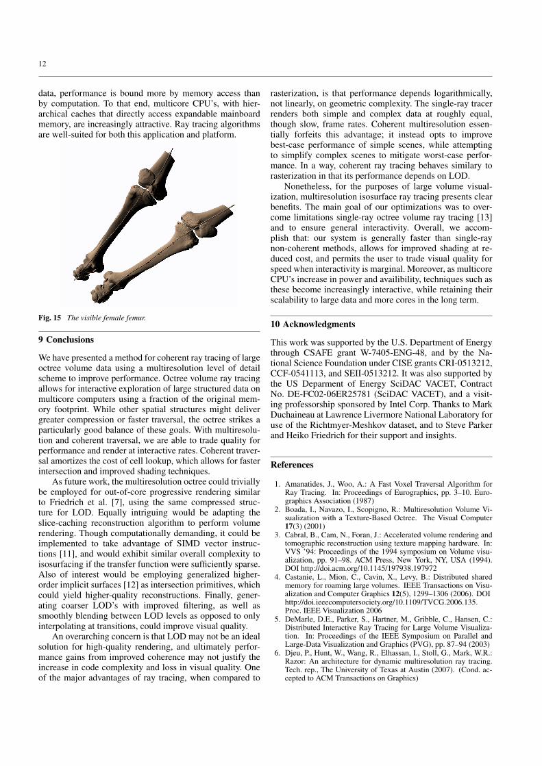
render that range on a machine with 2 GB RAM (Table 1).This method is even better suited for medical data such asthe visible female femur, when the user is specifically in-terested in bone or skin ranges. The full original CT scanhas highly-variant, homogeneous data for soft tissue iso-values from 0-100, causing the octree volume to actuallyexceed the original data in footprint. However, consideringonly the bone isovalues 100-163, we achieve nearly 20:1compression (Table 1). Not coincidentally, such “solid” datasegments are best suited for visualization via isosurfacing(Fig. 15).
Construction Performance and Filtering
The bottom-up octree build algorithm is O(N) with regard tothe total number of voxels; nonetheless N can be quite large.On a single core of a 16-core 2.4 GHz Opteron workstation,building a single timestep of the 3023 heptane volume re-quires a mere 8 seconds and negligable memory footprint;whereas a timestep of the Richtmyer-Meshkov data requires45 minutes and a footprint of nearly 40 GB. The build it-self creates an expanded full octree structure that occupies afootprint of four times the raw volume size. Thus, buildingoctree volumes from large data requires a 64-bit workstation.Although an offline process, parallelizing and optimizing thebuild would be both desirable and feasible as future work.In addition, the current construction algorithm effectivelysamples coarser resolutions via recursive clustered averag-ing. Superior LOD quality could be achieved with bilinearor higher-order filtering.
Memory Footprint Comparison
Octrees generally occupy 20%-30% the memory footprintof the uncompressed grid data, including both the multires-olution LOD structure and min/max acceleration tree. Con-versely, storing a full 3D array for each power-of-two LODvolume would approach twice the footprint of the originaluncompressed volume. Other ray-tracing efficiency struc-tures such as implicit kd-trees [27] could require up to twicethe full data footprint, often with an additional overhead ofaround 15% for cache-efficient bricking [22]. Thus, octreescompare favorably to other volume ray tracing structures.
8.2 Coherent Traversal Analysis
The main purpose of our slice-based algorithmic enhance-ments, and indeed of traversal itself, is to minimize the num-ber of cells that must be intersected. By employing packetsand the breadth-first CGT frustum algorithm, we are ableto dramatically reduce both the computational and memoryaccess costs of traversal. Finally, when multiple rays in aSSE packlet intersect the same object, we may effectivelyperform up to four intersections for the price of one. Forthese reasons, we are able to achieve significant speedups onhighly coherent simple scenes. Even with moderately com-plex scenes where a pixel seldom contains more than onevoxel, and SIMD intersection yields little speedup, slice-based reconstruction effectively doubles performance (Ta-ble 2). Moreover, rendering time is strongly correlated with

10
the number of ray-cell intersections. Performance profilingreveals that only 5%-15% of CPU time is spent in traversal,compared to over 70% in reconstruction and intersection.
TRAV. LOOKUPS ISECS L/RAY I/RAY FPSsingle 314707 166719 1.2 0.64 2.3packet 1187798 469560 4.5 1.8 .78+slice 1187798 469560 4.5 1.8 2.2+mcell 561889 124221 2.14 0.47 3.9+cell 270123 120514 1.0 0.47 4.6+mulres 98055 44419 0.37 0.17 7.6
Table 2 Results from clipping optimizations when ray-casting a mod-erately complex scene with low primitive-level coherence, from theheptane fire dataset (HEP302, Table 3). We compare single-ray traver-sal and 8x8 octree-CGT packet traversal with and without optimiza-tions. +slice: use slice-based cell reconstruction. +mcell: clip the deep-est macrocell slice extents to discard nodes not containing the isovalue.+cell: clip the cell slice extents to the set of active rays. +mulres: mul-tiresolution scheme, with dP/dV = 1. Tests at 5122 using one core ofan Intel Core Duo 2.16 GHz.
SCENE HEP64 HEP302 RMI/RAY FPS I/RAY FPS I/RAY FPS
single 0.70 1.9 0.64 2.3 3.58 0.57coherent2x2 0.26 4.3 0.5 2.84 5.65 0.384x4 0.11 9.7 0.45 4.54 7.94 0.338x8 0.058 14.4 0.47 4.6 12.4 0.2216x16 0.041 14.5 0.50 2.81 20.5 0.08
Table 3 Results with coherent packets, showing the net number ofintersections per ray and frames per second with a single-ray tracer,and our coherent system with varying packet sizes. We examine threescenes of increasing complexity. Leftmost (HEP64) is the 643 down-sampled heptane data, which has high intersection-level coherence.The full 3023 heptane data (HEP302) has low intersection-level coher-ence, but benefits from coherent traversal. The 20483 RM data yieldseven less coherence, and is a pathological case for packet traversal.Benchmarks on a single core of an Intel Core Duo 2.16 GHz, with a5122 frame buffer and multiresolution disabled.
Packet sizeFor performance reasons, our implementation chooses astatic packet size for traversal. This is appropriate for ourapplication, as we seek to render isosurfaces with constantcomplexity. Later, we enforce this via the pixel to voxelwidth ratio in the LOD scheme. Empirically, we find thatpackets of 8x8 work best for scenes where one to 4 raysintersect a common cell. 16x16 packets yield little benefiteven for simple data, and perform poorly on complex scenesof large data (Table 3).
Incoherent behavior without multiresolutionComplex scenes reveal the shortcoming of coherent traver-sal. Because traversal is not computed on a per-ray basis, but
solely from the packet frustum corners, it frequently looksup cells that would have been correctly ignored by a moreexpensive single-ray traverser. Our clipping optimizations(Figs. 7, 8) noticeably alleviate this, as we can see in Table 2.However, for complex scenes such as far views of large data,rendering cost is totally bound by intersection (Table 3). Ul-timately, frustum-based traversal causes large numbers ofcells to be looked up, though no rays in the packet actuallyintersect them. This in turn causes many unnecessary inter-section tests to be performed. Successful intersection testsare no less expensive, as packlet-cell intersection degener-ates to single-ray performance without primitive-level co-herence. These higher costs eventually overwhelm any gainsmade by more efficient traversal, and cause the coherentray tracer, without multiresolution, to perform worse thana single-ray algorithm on sufficiently complex scenes.
8.3 Multiresolution Results
The combination of multiresolution level of detail and co-herence enables frame rates up to an order of magnitudefaster for coherent scenes. With large volume data and smallframe buffers, coherence is less common; but in general it ispossible to decrease dP/dV to achieve interactive frame ratesand interesting, albeit coarser-quality, representations of thedata. For highly entropic large volume data, this behavioris frequently useful as coarser LODs inherently possess lessvariance, thus manifest less aliasing. However, coarser LODrendering are also less correct with respect to the originalresolution, as shown in Fig. 13.
Fig. 13 Qualitative impact of multiresolution on the Richtmyer-Meshkov data at t=270, isovalue 20. Top left to bottom right: single-ray, then coherent multiresolution with dP/dV of 1,2 and 4. On an IntelCore Duo 2.16 GHz with a 5122 frame buffer, these render at 0.92, 1.0,1.9, and 3.6 FPS respectively. To illustrate LOD transitions, like colorsindicate the same resolution.

11
Quality ComparisonFig. 16 in the Appendix compares quality with and withoutmultiresolution at dP/dV = 1, with forward and centraldifferences gradients. The bottom images show per-pixeldifferences (computed using 1 − abs(re f erence − image)per color channel), comparing multiresolution and non-multiresolution results, both rendered as white surfaces onblack background. In reproducing major features, renderingswith and without multiresolution look essentially identical.However, the difference images reveal that though mostfeatures remain intact, actual isosurfaces are slightly offsetwhen rendered at varying resolution – this accounts for theblack pixels (shown in closeup) where the surface exists atone resolution but not another. Otherwise, most differenceslie in the intensity of the gradient at different resolutions, asevidenced by grayscale pixels in the difference images.
Overall PerformanceIn best-case scenarios, our system significantly outperformsthe single-ray tracer. With close camera views of the RMdata and dP/dV = 1, we see order-of-magnitude improve-ment (Table 4). The coherent technique usually yields mod-est improvements even for scenes with generally poor co-herence. For sufficiently far camera angles viewing complexdata, the single-ray system may actually outperform the co-herent method, when using a LOD dP/dV = 1. For thesepathological cases, we recommend relaxing dP/dV for ex-ploration, or resorting to single-ray traversal for quality.
Coherent traversal handles a difficult scenario for thesingle-ray system: a close-up scene deep within the volume,with an isovalue for which the min/max tree is particularlyloose. Such is the case in the last example of Table 4. Whilesingle-ray suffers from data access demand, coherent traver-sal largely amortizes these costs and performs comparablyto other scenes with similar complexity.
Another substantial advantage of coherence is that largeframe buffers can be rendered relatively faster. Doublingthe frame buffer dimensions generally causes a factor offour slowdown in a single-ray tracer; by comparison thepacket system frequently experiences a factor of two orbetter performance decrease, particularly when higher res-olution leads to improved intersection-level coherence. Forthe dataset in Fig. 15, coherent ray tracing scales well tolarge frame buffers. This dataset renders at 6.0 FPS at 5122,versus 3.1 FPS at 10242 on an Intel Core Duo 2.16 GHz,with central differences and shadows.
8.4 Comparison to Existing Systems
Table 4 shows performance for the Richtmyer Meshkovdataset with our coherent multiresolution system withdP/dV = 1; and the single-ray implementation [13] with nomultiresolution scheme. In the best-case scenario we achievea factor of 23 faster than single-ray performance, and evenin worst cases the coherent multiresolution implementationdoes not exhibit substantially inferior performance. Thesenumbers compare favorably to other implementatations.
SCENE C.Duo,5122 Xeon,5122 Xeon,10242
single 8x8 single 8x8 single 8x850, far 2.5 3.5 14.5 19.5 4.5 6.5150, far 1.9 2.5 11.1 15.0 3.4 4.9270, far 1.1 1.1 7.2 12.4 2.2 2.250, close 2.0 6.9 12.1 39.8 3.6 14.2150, close 1.7 8.1 12.0 44.2 3.5 14.6270, close 0.2 4.7 1.4 38.6 0.4 9.2
Table 4 Framerates of various time steps of the Richtmyer-Meshkovdata, on an 2-core Intel Core Duo 2.16 GHz laptop (2 GB RAM) and an8-core dual 3 GHz Intel Xeon (Clovertown) with 4 GB RAM; with ourcoherent multiresolution method with 8x8 packets and dP/dV = 1, andsingle-ray without multiresolution [13]. Refer to Fig. 14 for images.
Fig. 14 Richtmyer-Meshkov results. From left to right, timesteps 50,150 (isovalue 20), and 270 (isovalue 160). Top: various close-up cam-era views, illustrating highly coherent scenes. Bottom: far views ex-hibiting generally poor coherence. We use dP/dV = 1.
For similar camera positions, we achieve the same 2 FPSRM data performance on an two-core Intel Core Duo asDeMarle et al. [5] report on a 64-processor cluster with adistributed shared memory layer. We are competitive withWald et al. [27] for far views, and perhaps faster for close-up scenes, while generally requiring an order of magnitudelesser memory footprint. The performance of our system isalso on par with that of Friedrich et al. [7]; however suchcomparison is not completely fair as that system employsLOD for progressive as opposed to dynamic rendering.
Comparison with state-of-the-art GPU methods is moredifficult. Clearly, slice-based direct-volume rasterization onthe GPU outperforms our method by well over an orderof magnitude for small data (less than 5123). For largerdata, this gap is less pronounced, but GPU DVR methodscan equally employ multiresolution compression schemeson blocks [9] and space-skipping and culling optimiza-tions [25]. These techniques are still limited by bus la-tency, and to our knowledge data the size of the Richtmyer-Meshkov has yet to be visualized at original data resolutionon a GPU. Out-of-core streaming and progressive render-ing, as well as multi-GPU distributed systems, are clearlyvalid approaches to large-scale volume visualization [4].However, multicore workstations are increasingly inexpen-sive commodities, and share a more straightforward andscalable programming model. Ultimately in rendering large
12
data, performance is bound more by memory access thanby computation. To that end, multicore CPU’s, with hier-archical caches that directly access expandable mainboardmemory, are increasingly attractive. Ray tracing algorithmsare well-suited for both this application and platform.
Fig. 15 The visible female femur.
9 Conclusions
We have presented a method for coherent ray tracing of largeoctree volume data using a multiresolution level of detailscheme to improve performance. Octree volume ray tracingallows for interactive exploration of large structured data onmulticore computers using a fraction of the original mem-ory footprint. While other spatial structures might delivergreater compression or faster traversal, the octree strikes aparticularly good balance of these goals. With multiresolu-tion and coherent traversal, we are able to trade quality forperformance and render at interactive rates. Coherent traver-sal amortizes the cost of cell lookup, which allows for fasterintersection and improved shading techniques.
As future work, the multiresolution octree could triviallybe employed for out-of-core progressive rendering similarto Friedrich et al. [7], using the same compressed struc-ture for LOD. Equally intriguing would be adapting theslice-caching reconstruction algorithm to perform volumerendering. Though computationally demanding, it could beimplemented to take advantage of SIMD vector instruc-tions [11], and would exhibit similar overall complexity toisosurfacing if the transfer function were sufficiently sparse.Also of interest would be employing generalized higher-order implicit surfaces [12] as intersection primitives, whichcould yield higher-quality reconstructions. Finally, gener-ating coarser LOD’s with improved filtering, as well assmoothly blending between LOD levels as opposed to onlyinterpolating at transitions, could improve visual quality.
An overarching concern is that LOD may not be an idealsolution for high-quality rendering, and ultimately perfor-mance gains from improved coherence may not justify theincrease in code complexity and loss in visual quality. Oneof the major advantages of ray tracing, when compared to
rasterization, is that performance depends logarithmically,not linearly, on geometric complexity. The single-ray tracerrenders both simple and complex data at roughly equal,though slow, frame rates. Coherent multiresolution essen-tially forfeits this advantage; it instead opts to improvebest-case performance of simple scenes, while attemptingto simplify complex scenes to mitigate worst-case perfor-mance. In a way, coherent ray tracing behaves similary torasterization in that its performance depends on LOD.
Nonetheless, for the purposes of large volume visual-ization, multiresolution isosurface ray tracing presents clearbenefits. The main goal of our optimizations was to over-come limitations single-ray octree volume ray tracing [13]and to ensure general interactivity. Overall, we accom-plish that: our system is generally faster than single-raynon-coherent methods, allows for improved shading at re-duced cost, and permits the user to trade visual quality forspeed when interactivity is marginal. Moreover, as multicoreCPU’s increase in power and availibility, techniques such asthese become increasingly interactive, while retaining theirscalability to large data and more cores in the long term.
10 Acknowledgments
This work was supported by the U.S. Department of Energythrough CSAFE grant W-7405-ENG-48, and by the Na-tional Science Foundation under CISE grants CRI-0513212,CCF-0541113, and SEII-0513212. It was also supported bythe US Deparment of Energy SciDAC VACET, ContractNo. DE-FC02-06ER25781 (SciDAC VACET), and a visit-ing professorship sponsored by Intel Corp. Thanks to MarkDuchaineau at Lawrence Livermore National Laboratory foruse of the Richtmyer-Meshkov dataset, and to Steve Parkerand Heiko Friedrich for their support and insights.
References
1. Amanatides, J., Woo, A.: A Fast Voxel Traversal Algorithm forRay Tracing. In: Proceedings of Eurographics, pp. 3–10. Euro-graphics Association (1987)
2. Boada, I., Navazo, I., Scopigno, R.: Multiresolution Volume Vi-sualization with a Texture-Based Octree. The Visual Computer17(3) (2001)
3. Cabral, B., Cam, N., Foran, J.: Accelerated volume rendering andtomographic reconstruction using texture mapping hardware. In:VVS ’94: Proceedings of the 1994 symposium on Volume visu-alization, pp. 91–98. ACM Press, New York, NY, USA (1994).DOI http://doi.acm.org/10.1145/197938.197972
4. Castanie, L., Mion, C., Cavin, X., Levy, B.: Distributed sharedmemory for roaming large volumes. IEEE Transactions on Visu-alization and Computer Graphics 12(5), 1299–1306 (2006). DOIhttp://doi.ieeecomputersociety.org/10.1109/TVCG.2006.135.Proc. IEEE Visualization 2006
5. DeMarle, D.E., Parker, S., Hartner, M., Gribble, C., Hansen, C.:Distributed Interactive Ray Tracing for Large Volume Visualiza-tion. In: Proceedings of the IEEE Symposium on Parallel andLarge-Data Visualization and Graphics (PVG), pp. 87–94 (2003)
6. Djeu, P., Hunt, W., Wang, R., Elhassan, I., Stoll, G., Mark, W.R.:Razor: An architecture for dynamic multiresolution ray tracing.Tech. rep., The University of Texas at Austin (2007). (Cond. ac-cepted to ACM Transactions on Graphics)

13
7. Friedrich, H., Wald, I., Slusallek, P.: Interactive Iso-Surface RayTracing of Massive Volumetric Data Sets. In: Proceedings of the2007 Eurographics Symposium on Parallel Graphics and Visual-ization (2007)
8. Gribble, C., Ize, T., Kensler, A., Wald, I., Parker, S.G.: A coher-ent grid traversal approach to visualizing particle-based simulationdata. Tech. Rep. UUSCI-2006-024, SCI Institute, University ofUtah (conditionally accepted at ACM Transactions on Graphics,2006) (2006)
9. Guthe, S., Wand, M., Gonser, J., Straßer, W.: Interactive Render-ing of Large Volume Data Sets. In: Proceedings of the conferenceon Visualization ’02, pp. 53–60. IEEE Computer Society (2002)
10. Igehy, H.: Tracing Ray Differentials. In: Computer Graphics (Pro-ceedings of ACM SIGGRAPH), pp. 179–186 (1999)
11. Knittel, G.: The ULTRAVIS System. In: Proceedings of the 2000IEEE symposium on Volume visualization, pp. 71–79. ACM Press(2000). DOI http://doi.acm.org/10.1145/353888.353901
12. Knoll, A., Hijazi, Y., Wald, I., Hansen, C., Hagen, H.: InteractiveRay Tracing of Arbitrary Implicit Functions with SIMD IntervalArithmetic. In: Proceedings of the 2007 Eurographics/IEEE Sym-posium on Interactive Ray Tracing (2007)
13. Knoll, A., Wald, I., Parker, S., Hansen, C.: Interactive IsosurfaceRay Tracing of Large Octree Volumes. In: Proceedings of theIEEE Symposium on Interactive Ray Tracing (2006)
14. Kraus, M., Ertl, T.: Adaptive Texture Maps. Proceedings ofACM SIGGRAPH/Eurographics Workshop on Graphics Hard-ware (2002)
15. LaMar, E., Hamann, B., Joy, K.I.: Multiresolution Techniques forInteractive Texture-based VolumeVisualization. In: ProceedingsIEEE Visualization 1999 (1999)
16. Levoy, M.: Efficient Ray Tracing for Volume Data. ACM Trans-actions on Graphics 9(3), 245–261 (1990)
17. Liu, Z., Finkelstein, A., Li, K.: Improving Progressive View-Dependent Isosurface Propagation. Computers & Graphics 26(2),209–218 (2002)
18. Livnat, Y., Hansen, C.D.: View Dependent Isosurface Extraction.In: Proceedings of IEEE Visualization ’98, pp. 175–180. IEEEComputer Society (1998)
19. Livnat, Y., Tricoche, X.: Interactive Point-based Isosurface Ex-traction. In: Proceedings of IEEE Visualization 2004, pp. 457–464(2004)
20. Lorensen, W.E., Cline, H.E.: Marching Cubes: A High Resolution3D Surface Construction Algorithm. Computer Graphics (Pro-ceedings of ACM SIGGRAPH) 21(4), 163–169 (1987)
21. Marmitt, G., Friedrich, H., Kleer, A., Wald, I., Slusallek, P.: Fastand Accurate Ray-Voxel Intersection Techniques for Iso-SurfaceRay Tracing. In: Proceedings of Vision, Modeling, and Visualiza-tion (VMV), pp. 429–435 (2004)
22. Parker, S., Parker, M., Livnat, Y., Sloan, P.P., Hansen, C., Shirley,P.: Interactive Ray Tracing for Volume Visualization. IEEE Trans-actions on Computer Graphics and Visualization 5(3), 238–250(1999)
23. Parker, S., Shirley, P., Livnat, Y., Hansen, C., Sloan, P.P.: Interac-tive Ray Tracing for Isosurface Rendering. In: IEEE Visualization,pp. 233–238 (1998)
24. Reshetov, A., Soupikov, A., Hurley, J.: Multi-Level Ray Trac-ing Algorithm. ACM Transaction of Graphics 24(3), 1176–1185(2005). (Proceedings of ACM SIGGRAPH)
25. Ruijters, D., Vilanova, A.: Optimizing GPU Volume Rendering.Winter School of Computer Graphics, Pilzen (2006)
26. Wald, I., Boulos, S., Shirley, P.: Ray tracing deformable scenes us-ing dynamic bounding volume hierarchices. Tech. Rep. UUSCI-2006-023, SCI Institute, University of Utah (conditionally ac-cepted at ACM Transactions on Graphics, 2006) (2006)
27. Wald, I., Friedrich, H., Marmitt, G., Slusallek, P., Seidel, H.P.:Faster Isosurface Ray Tracing using Implicit KD-Trees. IEEETransactions on Visualization and Computer Graphics 11(5), 562–573 (2005)
28. Wald, I., Ize, T., Kensler, A., Knoll, A., Parker, S.: Ray tracinganimated scenes using coherent grid traversal. In: Proceedings ofACM SIGGRAPH 2006) (2006)
29. Wald, I., Slusallek, P., Benthin, C., Wagner, M.: Interactive Ren-dering with Coherent Ray Tracing. Computer Graphics Forum20(3), 153–164 (2001). (Proceedings of Eurographics)
30. Westermann, R., Kobbelt, L., Ertl, T.: Real-time Exploration ofRegular Volume Data by Adaptive Reconstruction of Iso-Surfaces.The Visual Computer 15(2), 100–111 (1999)
31. Wilhelms, J., Gelder, A.V.: Octrees For Faster Isosurface Genera-tion. ACM Transactions on Graphics 11(3), 201–227 (1992)
32. Yoon, S.E., Lauterbach, C., Manocha, D.: R-lods: Fast lod-basedray tracing of massive models. The Visual Computer (Proc. PacificGraphics 2006) 22(9-11), 772–784 (2006)
A Coherent Octree Traversal Algorithm
In this pseudocode, duv and euv are SSE vector variables, and k is an in-teger. Cap depth is dcap = dmax −1. For multiresolution, the algorithmis similar except we may intersect slices at lesser stop depth than dmax.Also refer to Figs. 6,8, and 9 for illustration of this algorithm.
Algorithm 2 Octree CGT algorithmRequire: axes K,U,V; packet P; octree volume OV ; isovalueEnsure: compute P intersection with OV
for all depths i ∈ {0..dmax} doduv[i]⇐ [dumin,dvmin,dumax,dvmax] / 2dmax−i
k0[i]⇐ (P enters OV )K / 2dmax−i
k1[i]⇐ (P exits OV )K / 2dmax−i
euv[i]⇐ [umin,vmin,umax,vmax] at k0[i],k1[i]k[i]⇐ k0[i]knextMC[i]⇐ k[i]+2
end ford ⇐ 0while k[d]≤ k1[d] do
if k[d] = knextMC[d] thend ⇐ d−1continue
end iftraverseChild ⇐ f alse;for all u ∈ [umin,umax],v ∈ [vmin,vmax] of euv do
node ⇐ OV.lookup(vec3(k,u,v),d)if isovalue ∈ [node.min,node.max] then
traverseChild ⇐ truebreak
end ifend forif d = dcap then
clip euv to non-empty cap-level macrocellsend ifif traverseChild = true then
if d = dmax thenclip cell slice euv to active raysintersect P with slice k[dcap] at euv[dcap]if all rays in P hit then
returnend if
elseeuv[d]⇐ euv[d]+duv[d]knew[d +1]⇐ 2∗ k[d]k[d +1]⇐ knew[d +1]knextMC[d +1]⇐ k[d +1]+2d ⇐ d +1continue
end ifend ifeuv[dcap]⇐ euv[dcap]+duv[dcap]
end while

14
B Quality Comparison
Fig. 16 Qualitative comparison of results on the RM data, t=270, 10242 f ramebu f f er, using 8x8 packets. Top row: without multiresolution,with forward differences (left) and central differences (right), rendering at 1.8 and 1.3 fps, respectively. Middle row: color-coded multiresolutionwith dP/dV = 1, rendering at 4.2 and 3.1 fps for forward and central differences respectively. Bottom row: inverted differences between theresults with and without multiresolution. Benchmarks performed on an 8-core dual Intel Xeon 3 GHz desktop with 4 GB RAM.