CODE OF PRACTICE 41 - Academy for Healthcare Science · This document replaces BCGA Code of...
86
CODE OF PRACTICE 41 THE DESIGN, CONSTRUCTION, MAINTENANCE AND OPERATION OF FILLING STATIONS DISPENSING GASEOUS FUELS REVISION 1: 2016
Transcript of CODE OF PRACTICE 41 - Academy for Healthcare Science · This document replaces BCGA Code of...

CODE OF PRACTICE 41
THE DESIGN, CONSTRUCTION,
MAINTENANCE AND OPERATION OF
FILLING STATIONS DISPENSING
GASEOUS FUELS
REVISION 1: 2016

1 BCGA 41 – Revision 1
CODE OF PRACTICE 41
THE DESIGN, CONSTRUCTION, MAINTENANCE
AND OPERATION OF FILLING STATIONS
DISPENSING GASEOUS FUELS
REVISION 1: 2016
Copyright © 2016 by British Compressed Gases
Association. First printed 2014. All rights reserved. No
part of this publication may be reproduced or transmitted
in any form or by any means, electronic or mechanical,
including photocopy, without permission from the
publisher:
BRITISH COMPRESSED GASES ASSOCIATION Registered office: 4a Mallard Way, Pride Park, Derby, UK. DE24 8GX
Company Number: 71798, England
Website:
www.bcga.co.uk
ISSN 0260 - 4809

2 BCGA 41 – Revision 1
PREFACE
The British Compressed Gases Association (BCGA) was established
in l971, formed out of the British Acetylene Association, which
existed since l901. BCGA members include gas producers, suppliers
of gas handling equipment and users operating in the compressed gas
field.
The main objectives of the Association are to further technology, to
enhance safe practice, and to prioritise environmental protection in the
supply and use of industrial, food and medical gases, and we produce
a host of publications to this end. BCGA also provides advice and
makes representations on behalf of its Members to regulatory bodies,
including the UK Government.
Policy is determined by a Council elected from Member Companies,
with detailed technical studies being undertaken by a Technical
Committee and its specialist Sub-Committees appointed for this
purpose.
BCGA makes strenuous efforts to ensure the accuracy and current
relevance of its publications, which are intended for use by technically
competent persons. However this does not remove the need for
technical and managerial judgement in practical situations. Nor do
they confer any immunity or exemption from relevant legal
requirements, including by-laws.
For the assistance of users, references are given, either in the text or
Appendices, to publications such as British, European and
International Standards and Codes of Practice, and current legislation
that may be applicable but no representation or warranty can be given
that these references are complete or current.
BCGA publications are reviewed, and revised if necessary, at five-
yearly intervals, or sooner where the need is recognised. Readers are
advised to check the Association’s website to ensure that the copy in
their possession is the current version.
This document has been prepared by BCGA Technical Sub-
Committee 9. This document replaces BCGA Code of Practice 41:
2012. It was approved for publication at BCGA Technical Committee
153. This document was first published on 20/04/2016. For
comments on this document contact the Association via the website
www.bcga.co.uk.

3 BCGA 41 – Revision 1
CONTENTS
Section Page
TERMINOLOGY AND DEFINITIONS 6
1. INTRODUCTION 12
2. SCOPE 16
3 RISK MANAGEMENT 18
3.1 General 18
3.2 Principle Legal Requirements 19
3.3 Risk Assessments 20
4 PRE-DESIGN 20
5 PLANNING PERMISSION AND PERMITS 22
5.1 General 22
5.2 Storage 22
5.3 Multi-Fuel Stations 22
6. LAYOUT AND SITE SELECTION CRITERIA 23
6.1 General 23
6.2 Location of storage installation 24
6.3 Access and egress for fuel delivery vehicles 27
6.4 Location of dispensing points 29
6.5 Connecting pipework 31
6.6 On-site fuel generation equipment and related process
equipment.
31
6.7 Vent systems 32
6.8 Vent recovery 32
6.9 Other filling station activities 32
7. DESIGN OF FILLING STATION 32
7.1 General 32

4 BCGA 41 – Revision 1
7.2 Fuel gas storage and process equipment 39
7.3 LNG vapouriser 42
7.4 Fuel delivery 43
7.5 Connecting pipework and valves 43
7.6 Dispensing equipment 44
7.7 Venting and vent stacks 48
7.8 Dispenser plinth earthing and grounding 49
7.9 Canopy 49
7.10 Gas fuels on multi-fuel stations 49
8. INSTALLATION AND COMMISIONING 49
8.1 Installation 49
8.2 Pre-commissioning 49
8.3 Commissioning 52
8.4 Handover for operation 53
8.5 End of life 55
9. OPERATION 55
9.1 Delivery 55
9.2 Vehicle filling – Fuel dispense 56
10. PERIODIC EXAMINATION & MAINTENANCE 57
11. FUEL QUALITY 60
11.1 Proton Exchange Membrane hydrogen 60
11.2 Non-Proton Exchange Membrane hydrogen 61
11.3 CNG and LNG 61
12. COMPETENCE OF PERSONNEL INCLUDING TRAINING 62
13. PERSONNAL PROTECTIVE EQUIPMENT 66
13.1 Public access filling 66
13.2 Non-public access filling 66

5 BCGA 41 – Revision 1
13.3 Maintenance and fuel delivery 66
14. EMERGENCY SITUATIONS AND PROCEDURES 66
15. REFERENCES * 69
APPENDICES:
APPENDIX 1 Minimum recommended separation distances for hydrogen
storage installations
78
APPENDIX 2 Minimum recommended separation distances for natural gas
storage installations
79
APPENDIX 3 Hydrogen - General data and safety considerations 80
APPENDIX 4 Natural gas - General data and safety considerations 82
APPENDIX 5 Checklist for approval to install and operate filling stations 84
* Throughout this document numbers in brackets refer to references in Section 15.
Documents referenced are the edition current at the time of publication of this Code of
Practice, unless otherwise stated.

6 BCGA 41 – Revision 1
TERMINOLOGY AND DEFINITIONS
Assembly A number of parts or combination thereof that are joined
together to perform a specific function and subject to
disassembly without degradation of any of the parts, e.g. a
hose assembly combining a nozzle, hose set and breakaway
coupling.
Biomethane Biomethane is upgraded Biogas, a natural occurring gas with
similar properties to natural gas, produced by the anaerobic
digestion of waste such as organic matter, food waste, sewage,
landfill etc. It can be stored in two forms, compressed (CBG)
or liquefied (LBG).
Boil-off gas Boil-off of natural gas emissions caused by the evaporation of
a liquefied gas in storage tanks and other parts of the station.
Break-away device
A device that stops the flow of gas allowing safe
disconnection from the fuelling system in the event of
accidental disconnection, i.e. a vehicle drive-away when the
hose is still connected.
Bulk storage For the purposes of this document bulk storage is defined as
fuel gas storage which consists of either:
fixed gas cylinders manifolded together; or
tubes which may be either fixed in place or mounted on
a transportable trailer; or
one or more liquefied gas vessels.
Bundle
Assembly of cylinders that are fastened together and which are
interconnected by a manifold and transported as a unit, having
a total water capacity not exceeding 3000 litres.
Bund A containment structure typically made of concrete that
diverts a liquefied gas to a safe area for dissipation into the
atmosphere.
Canopy A roof, overhead shelter, or hood providing the station or fuel
dispenser with a degree of weather protection.

7 BCGA 41 – Revision 1
Competent Person A person with enough theoretical and practical knowledge,
training and actual experience to carry out a particular task
safely and effectively. The person should have the necessary
ability in the particular operation of the type of plant and
equipment with which they are concerned, an understanding of
relative statutory requirements and an appreciation of the
hazards involved. That person should also be able to
recognize the need for specialist advice or assistance when
necessary and to assess the importance of the results of
examinations and tests. A ‘person’ can be taken to mean more
than one, or a body corporate or incorporate. It is therefore
possible to appoint appropriate organisations (e.g. inspection
bodies or insurance companies) to carry out tasks designated
for competent persons.
Compressed natural gas Compressed natural gas (CNG), including methane and
biomethane.
Control point A position in a kiosk or other building at an attended self-
service filling station from which an attendant can view and
supervise activities at the dispenser, activate the equipment,
and shut-off the dispense, in the case of emergency.
Cryogenic Cryogenic liquids are liquefied gases that are kept in their
liquid state at very low temperatures, lower than -150°C.
Cylinder Transportable pressure receptacle of a water capacity not
exceeding 150 litres.
Dead mans button /
switch
A device that automatically shuts down an operation in a safe
manner, i.e. when refuelling a vehicle or during a fuel transfer.
Automatically operated if the operator releases pressure on the
button/switch.
Deflagration A rapid chemical reaction in which the output of heat is
sufficient to enable the reaction to proceed and be accelerated
without input of heat from another source. Deflagration is a
surface phenomenon with the reaction products flowing away
from the unreacted material normal to the surface at subsonic
velocity. The effect of a deflagration under confinement is an
explosion. Confinement of the reaction increases pressure rate
of reaction and temperature and may cause transition into a
detonation.
Detonation
An exothermic reaction wave which follows, and also
maintains, a supersonic shock front from an explosion. Such
transitions are promoted by the increased turbulence arising
from a deflagration flame front interacting with strong
structures.

8 BCGA 41 – Revision 1
Dispenser Pump or equipment used to dispense fuel at a filling station.
Docking station A docking station is a housing, pad or post where the
dispenser nozzle is stored to prevent damage, ingress of dirt,
or moisture. A docking station for an LNG nozzle may be
heated to prevent the build up of ice and condensation.
Dry air Air with a maximum dew point of -40 ºC.
Embrittlement Embrittlement is a loss of ductility of a material making it
brittle. Embrittlement of some carbon steels may be caused as
a result of exposure to low temperature gases, for example,
from a liquefied gas. Hydrogen embrittlement is the effect of
hydrogen absorption on some metals and alloys. The
degradation of a structural material may result in failure or a
leak.
Explosion A nuclear, chemical or physical process leading to the sudden
release of energy (and usually gases and heat) giving rise to
external pressure waves.
Equipment supplier /
installer
The company or companies, as contracted by the Owner /
User, to provide and install the equipment used to store,
distribute and dispense a specific fuel gas.
Fast-fill For natural gas, a filling operation that takes a similar amount
of time as current liquid fuels to fill.
Filling station A facility for the storage and dispensing, normally to the
general public, of products used as fuels for motor vehicles.
These can include petrol, diesel, autogas (LPG), hydrogen,
CNG, LNG and LCNG.
NOTE: Hydrogen filling stations may typically be referred to
as Hydrogen Refuelling Stations (HRS), however the term
filling station is used for consistency with other UK
documents concerning petrol, diesel and LPG filling stations.
Flammable gas Gases which at 20 °C and at standard atmospheric pressure:
(i) are ignitable when in a mixture of 13 % or less by
volume with air; or
(ii) have a flammable range with air of at least 12
percentage points regardless of the lower flammability limit.
Forecourt attendant Responsible to the Site Operator. Directly operates and
controls the dispenser and the discharge nozzle on behalf of
the customer.

9 BCGA 41 – Revision 1
Gas supplier The company contracted by the Owner / User to provide a
specific fuel gas product for dispense at the filling station.
Gaseous storage A system which includes containers, pressure regulators,
instruments, safety-relief devices, manifolds, inter-connecting
piping and controls. The storage system terminates at the
point where the gas enters the distribution piping.
Hazardous area Any place in which an explosive atmosphere may occur in
quantities such as to require special precautions to prevent
ignition during construction, installation or use, as applicable.
Heavy goods vehicle Heavy Goods Vehicle (HGV) (also known as LGV, Large
Goods Vehicle). Commercial truck with a gross combination
mass of more than 3500 kg.
Installation
Equipment (vessels, pumps, compressors, electrolysers,
reformers etc.), pipework, hoses, valves, instruments etc. that
have been assembled into one or more systems that enable the
generation, storage or dispensing of gaseous fuels.
Invacuation A variant of the commonly understood concept of evacuation
(for example, in the event of a fire). Invacuation involves the
removal of people to an alternative area within the site.
Leakage See Methane Leakage
Liquefied Compressed
Natural Gas (LCNG)
LNG warmed and vapourised to product CNG for dispensing
Liquefied natural gas Liquefied natural gas (LNG), including methane and
biomethane (LBG).
LNG Vapouriser LNG vapouriser is a heat exchanger used for regasifying
liquefied gases.
LPG Liquefied petroleum gas
Maintenance staff Typically employed by the equipment supplier / installer, or
the gas supplier. Has significant understanding of the design
and operational elements of both the gas dispensing and
storage / generation equipment, as appropriate.
May An option available to the user of this Code of Practice.
Methane leakage The loss, emission of methane due to leakage, venting,
coupling losses, for example, of the storage system. This
concept is distinct from that of ‘methane slip’, which concerns
poor combustion (combustion efficiency) i.e. in a vehicle
using an internal combustion engine. Methane leakage has an
undesirable environmental and safety impact.

10 BCGA 41 – Revision 1
Mobile storage For an LNG tank, an assembly having a gross volume of more
than 1,000 litres.
For cylinders or tubes, an assembly mounted on a vehicle or
trailer for transportation. (Refer also to bundle).
Mobile workers Persons who work in more than one place or travel as part of
their job, i.e. HGV and PSV drivers.
Multi-fuel dispenser Dispenser delivering multiple fuels, liquid or gaseous.
Non-hazardous area Any place in which an explosive atmosphere is not expected
to occur in quantities such as to require special precautions to
prevent ignition during construction, installation and use.
Odorization The process of adding an odorant to gas in order that it can be
detected by smell.
Owner / user The owner of a filling station. Within this Code of Practice
the owner has the same responsibilities as the user, as defined
in the Pressure Systems Safety Regulations 2000 (12).
Public service vehicle Public service vehicle (PSV). A vehicle such as a bus used by
members of the public to travel to and from places on
particular routes.
Self-service attendant Responsible to the site operator. Supervises customers
operating dispensers, with the responsibility to activate or, in
the case of emergency, shut-off the dispenser from a defined
control point.
Separation distances Horizontal and vertical distances between the nearest part of
the gas storage and distribution system and any specified
feature (for example, occupied buildings, facilities, process
areas, site boundary). The purpose of a separation distance is
to protect the gas storage and distribution system from heat
radiation should there be a fire in the local area, also to protect
the local area from the effects of a fuel gas release. The
intention is to provide sufficient time for emergency
evacuation as appropriate and the mobilisation of additional
fire-fighting equipment.
NOTE: The term separation distance should not be confused
with the distances involved with hazardous area classification.
Shall Identifies a mandatory requirement for compliance with this
Code of Practice.
Should Identifies a preferred, but not mandatory requirement for
compliance with this Code of Practice.

11 BCGA 41 – Revision 1
Site operator Responsible to the owner / user. Person (or company) in
charge of (with day to day control) a filling station i.e. the
petroleum spirit licence holder. In some cases this will be the
owner.
Slow-fill For natural gas, a slow (or timed) filling operation that takes a
longer amount of time than current liquid fuels to fill, and can
take several hours.
Tanker stand The position on a filling station where a fuel delivery tanker is
located during the fuel delivery process.
Tube Seamless transportable pressure receptacle of a water capacity
exceeding 150 litres but not more than 3000 litres.
Unattended self-service A filling station where the dispenser is activated and operated
by a customer without supervision by an attendant.
Venting Controlled and uncontrolled release of gas into the
atmosphere.
Vapour recovery
equipment
Recovers boil-off gas to prevent it from escaping into the
atmosphere. Equipment may include a receiver, ambient
vapouriser, compressor and buffer storage, enabling recovered
gas to be dispensed as CNG. It may also consist of an
assembly for re-liquefying boil-off gas from the vehicle fuel
tank or road tanker, which is returned as LNG to the station
storage vessel.
Vulnerable populations Vulnerable populations include those who may not be easy to
evacuate from premises because of, for example, age or
infirmity, including schools, hospitals, old people’s homes
and other residential accommodation.

12 BCGA 41 – Revision 1
CODE OF PRACTICE 41
THE DESIGN, CONSTRUCTION, MAINTENANCE AND OPERATION
OF FILLING STATIONS DISPENSING GASEOUS FUELS
1. INTRODUCTION
The use of alternative vehicle fuels is becoming more widespread in the UK. The use of
Liquefied Petroleum Gas (LPG) is well established, however, the technical and safety
requirements for other gaseous fuels are being developed, but they are still subject to UK
legislation or guidance.
Alternative gaseous fuels have a part to play in reducing UK carbon emissions, as recognised
in the European Commission Clean Power for Transport package of measures, which aims to
ensure the build-up of alternative fuel stations across Europe together with common standards
for their design and use. This package includes a European alternative fuels strategy,
European Communication 2013/17/EC (31), and a Directive on the deployment of a
European alternative fuels infrastructure, European Directive 2014/94/EU (29). The lack of
UK industry guidelines complicates the design, planning and approval processes for these
filling stations foreseen by these European initiatives.
A number of international standards, national standards and industry documents from other
countries relating to the design and operation of alternative fuel vehicle filling stations have
been published, or are currently in the process of being developed.
The British Compressed Gases Association (BCGA) recognises that the alternative gaseous
fuels industry is still developing and seeks, at this point in time, to provide a guidepost
document that combines the most important points of multiple guidance documents as
referenced.
The BCGA acknowledges that there are discrepancies between several of these documents
and that there will inevitably be revisions required in future. However, given the legally-
binding UK national requirement to reduce carbon emissions, the BCGA has taken the
decision to publish this guidepost document to facilitate the timely development of alternative
gaseous filling station networks.
The BCGA seeks to provide with this Code of Practice a minimum industry standard to
ensure a consistent high level of safety and to provide a reference document for those
involved in the design, planning, operation and regulatory approval of alternative gaseous
fuel stations.
The BCGA will review this document at intervals to continually reflect the experience of this
growing industry and welcomes suggestions from interested parties.
This code of practice is intended to outline the major technical and safety considerations
required in the UK during the design, construction, maintenance and operation of vehicle
filling stations which incorporate filling facilities for Liquefied Natural Gas (LNG),
Compressed Natural Gas (CNG) and hydrogen (H2), drawn from existing BCGA publications

13 BCGA 41 – Revision 1
and other major documents in order to comply with more general safety regulations and to
ensure safe operation.
For more traditional fuels such as petrol, diesel and LPG , the primary publication for the
requirements of the design, construction, modification, maintenance and decommissioning of
filling stations, published by the Association for Petroleum and Explosives Administration
(APEA) and Energy Institute (EI), is the Design, construction, modification, maintenance
and decommissioning of filling stations (The Blue Book) (94). It has been produced jointly
by the APEA and the EI with input from the Health and Safety Executive (HSE) and other
industry stakeholders.
Where gaseous fuels and traditional fuels are dispensed at the same filling station, due regard
should be taken of both this code of practice and the Blue Book (94). In such cases, this code
of practice is designed to be complementary to the Blue Book (94) in relation to the
alternative fuel elements.
There are differences between the various gaseous fuels covered by this code of practice and
these should be taken into account.
Whilst both CNG and gaseous hydrogen are typically stored at high pressure, the pressures
involved in hydrogen vehicle filling are likely to be considerably higher than those involved
with CNG vehicle filling. The risk of harm / damage to the surroundings due to leakage from
the installation should therefore take into consideration the storage and operational pressures
of the gas, and may require more extensive safeguards for high pressure hydrogen systems. It
is likely however that both CNG and hydrogen fuel installations will have the same risk of
damage by 3rd
parties etc. Thus civil engineering protection of both types of filling stations is
similar.
The principle hazards associated with hydrogen are:
Flammability;
Asphyxiation;
Material embrittlement and subsequent mechanical failure;
Increased likelihood of leakage from joints, due to smaller molecular size and
where applicable, higher pressures;
Undetected leaks due to lack of odour;
Undetected fire due to invisible flame;
Increased likelihood of ignition of a leak;
For liquid hydrogen, cold burns when exposed to the skin;
Increased risk of injury as a result of uncontrolled release of high pressure gas;

14 BCGA 41 – Revision 1
Potential transition of an explosion from deflagration to detonation.
CNG and LNG are relatively new road fuels in the UK. Although natural gas as an energy
source for domestic households, commercial property and industry is well accepted, there are
major differences that have to be observed when using natural gas as a road fuel.
CNG is natural gas that has been compressed to a high pressure, typically 200 to 300 bar (20
to 30 MPa) in order that large volumes of energy can be stored, enabling it to be used in
vehicles as a replacement or substitute to current liquid fuels. The high-pressure gas can be
stored in steel or composite cylinders of various diameters and lengths.
The principle hazards associated with CNG are as follows:
Flammability;
Asphyxiation;
Undetected leaks due to lack of odour;
Undetected fire due to invisible flame;
Increased risk of injury as a result of uncontrolled release of high-pressure gas.
LNG is natural gas in a liquid form, as a cryogenic it is cooled to approximately -162 ºC. It is
mainly used as an energy source for heavy-duty road transport and can be converted back
into a gaseous state when delivered to a cryogenic storage vessel and warmed to ambient
temperature.
The principle hazards associated with LNG are as follows:
Flammability;
Asphyxiation;
Cold burns when exposed to the skin;
Undetected leaks due to lack of odour;
Undetected fire due to invisible flame;
Material low-temperature embrittlement and subsequent mechanical failure (to
mild and carbon steels);
If LNG is released it vapourises. The vapours are initially heavier than air and
will form a gas cloud close to the ground, which will eventually dissipate. However,
under specific conditions, where a vapour cloud exists with LNG between its lower and
higher flammability limits in air (5 % to 15 %), if a source of ignition is present the

15 BCGA 41 – Revision 1
vapour cloud could ignite, and this may be some distance from the actual release
source. Vapour clouds also introduce hazards from the visual impairment they create.
Other specific considerations are outlined in Appendix 4.
Some of the important international reference documents addressing the design and operation
of hydrogen vehicle filling stations include:
ISO/TS 20100 (56), Gaseous hydrogen. Fuelling stations. (Document
withdrawn, reference only).
USA - NFPA 2 (100), Hydrogen technologies code.
Germany - VdTÜV MB DRGA 514 (104), Requirements for hydrogen fuelling
stations, Compressed gases 514.
Some of the important international reference documents addressing the design and operation
of CNG vehicle filling stations include:
The Institute of Gas Engineers and Managers (IGEM) UP/20 (90), Natural gas
fuelling stations.
USA - NFPA 52 (101), Vehicular gaseous fuel systems code.
Germany - G651/vdTUV M510 (103), Natural gas stations.
Netherlands – PGS 25 (105), Natural gas delivery systems for vehicles.
Israel - SI 6236 (107), Compressed natural gas (CNG) fuelling stations for
vehicles.
ISO 16923 (52), CNG stations for fuelling vehicles. (Draft standard).
Some of the important international reference documents addressing the design and operation
of LNG vehicle filling stations include:
NFPA 52 (101).
Netherlands – PGS 33 (106), Natural Gas. Liquefied natural gas (LNG) delivery
installations for vehicles.
ISO 16924 (53), Natural gas fuelling stations. LNG stations for fuelling vehicles.
(Draft standard).
IGEM/UP/21 (91), Liquid natural gas fuelling stations. (Draft under
development).
Other relevant documents that may be of interest to the reader are listed in Section 15.

16 BCGA 41 – Revision 1
This document is not a Design Code. The user of this Code of Practice shall make reference
where applicable to UK legislation and internationally recognised Standards where these
apply and should also take into account the specific practices of the UK industrial gases
companies.
All new installations or modifications to existing installations shall, as far as is reasonably
practicable, comply with this Code of Practice for the products or services involved.
This Code of Practice, along with the range of other BCGA publications, represents the
BCGA’s view of minimum requirements for safe practice.
2. SCOPE
This Code of Practice covers the location, design, installation, commissioning, operation,
maintenance and inspection of equipment used in a filling station for vehicle filling with
gaseous hydrogen, CNG, or LNG, with or without the dispensing of other vehicle fuels such
as petrol, diesel, Liquefied Petroleum Gas (LPG) etc.
This document covers the delivery or on-site generation of the fuel (including compression as
appropriate), and equipment associated with storage and dispensing of the fuels included in
the scope. It includes guidance on emergency procedures, appropriate signage, and the
requirement for competent operating staff for the site, it also covers those carrying out filling
activities, which may include members of the public.
Storage of the fuel may be as a compressed or liquefied gas.
Recommendations of best practice are outlined to assist in compliance with UK regulations to
ensure the safety of the general public, and employees at a vehicle filling station:
BCGA Code of Practice (CP) 4 (82), Industrial gas cylinder manifolds and gas
distribution pipework (excluding acetylene), covers small-scale storage and distribution
of gases in the UK.
BCGA CP 33 (83), The bulk storage of gaseous hydrogen at users’ premises,
covers storage and distribution of gaseous hydrogen in the UK.
BCGA CP 39 (84), In-service requirements of pressure equipment (gas storage
and distribution systems).
BCGA CP 46 (86), The storage of cryogenic flammable fluids, covers the storage
of liquid hydrogen and LNG in the UK.
IGEM UP/20 (90) covers the supply of natural gas from the grid or mobile CNG
storage, compression and dispensing of CNG to vehicles in the UK.
IGEM UP/21 (91) covers the supply of LNG from road tanker to storage and
dispensing of LNG vehicles and mobile stations in the UK.

17 BCGA 41 – Revision 1
Figure 1. LNG and CNG
Figure 2: Hydrogen
18 BCGA 41 – Revision 1
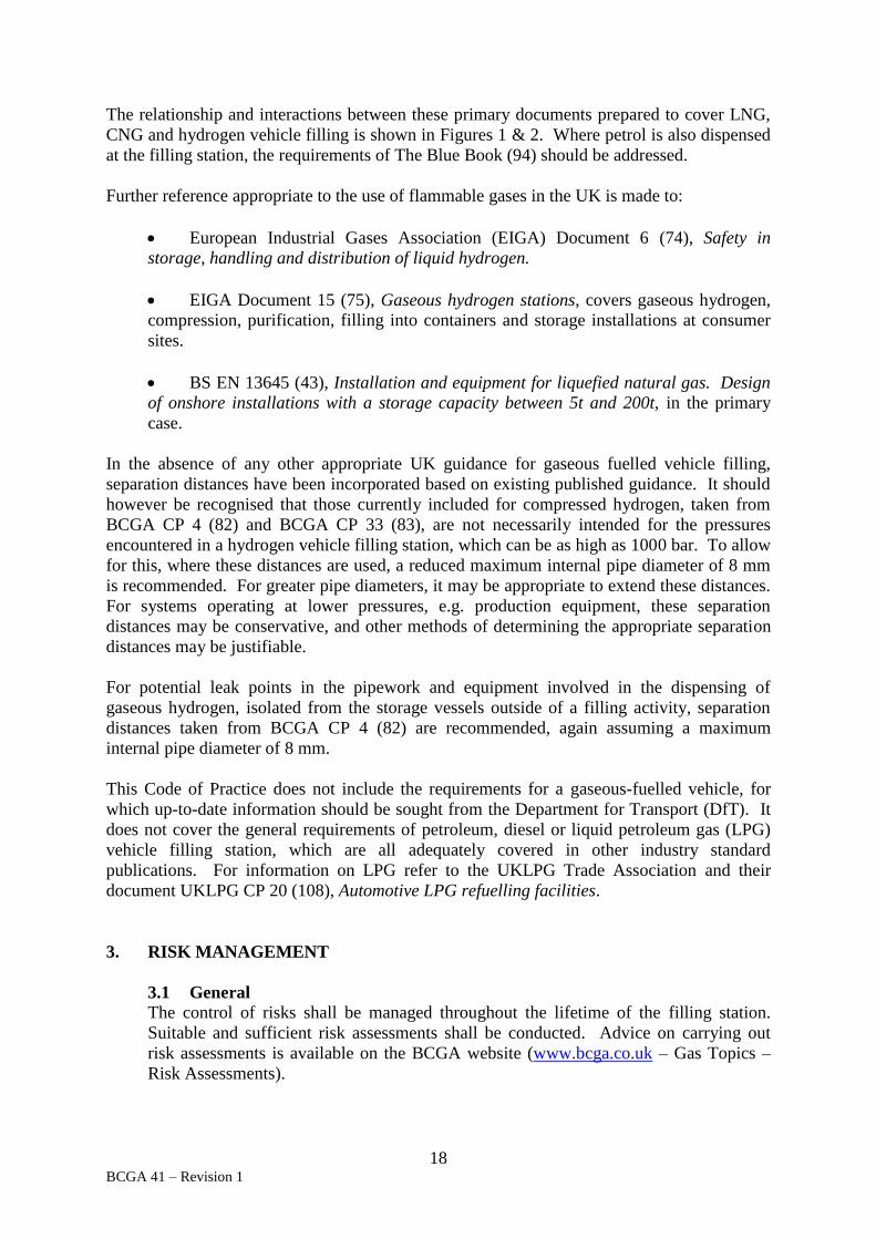
The relationship and interactions between these primary documents prepared to cover LNG,
CNG and hydrogen vehicle filling is shown in Figures 1 & 2. Where petrol is also dispensed
at the filling station, the requirements of The Blue Book (94) should be addressed.
Further reference appropriate to the use of flammable gases in the UK is made to:
European Industrial Gases Association (EIGA) Document 6 (74), Safety in
storage, handling and distribution of liquid hydrogen.
EIGA Document 15 (75), Gaseous hydrogen stations, covers gaseous hydrogen,
compression, purification, filling into containers and storage installations at consumer
sites.
BS EN 13645 (43), Installation and equipment for liquefied natural gas. Design
of onshore installations with a storage capacity between 5t and 200t, in the primary
case.
In the absence of any other appropriate UK guidance for gaseous fuelled vehicle filling,
separation distances have been incorporated based on existing published guidance. It should
however be recognised that those currently included for compressed hydrogen, taken from
BCGA CP 4 (82) and BCGA CP 33 (83), are not necessarily intended for the pressures
encountered in a hydrogen vehicle filling station, which can be as high as 1000 bar. To allow
for this, where these distances are used, a reduced maximum internal pipe diameter of 8 mm
is recommended. For greater pipe diameters, it may be appropriate to extend these distances.
For systems operating at lower pressures, e.g. production equipment, these separation
distances may be conservative, and other methods of determining the appropriate separation
distances may be justifiable.
For potential leak points in the pipework and equipment involved in the dispensing of
gaseous hydrogen, isolated from the storage vessels outside of a filling activity, separation
distances taken from BCGA CP 4 (82) are recommended, again assuming a maximum
internal pipe diameter of 8 mm.
This Code of Practice does not include the requirements for a gaseous-fuelled vehicle, for
which up-to-date information should be sought from the Department for Transport (DfT). It
does not cover the general requirements of petroleum, diesel or liquid petroleum gas (LPG)
vehicle filling station, which are all adequately covered in other industry standard
publications. For information on LPG refer to the UKLPG Trade Association and their
document UKLPG CP 20 (108), Automotive LPG refuelling facilities.
3. RISK MANAGEMENT
3.1 General
The control of risks shall be managed throughout the lifetime of the filling station.
Suitable and sufficient risk assessments shall be conducted. Advice on carrying out
risk assessments is available on the BCGA website (www.bcga.co.uk – Gas Topics –
Risk Assessments).

19 BCGA 41 – Revision 1
3.2 Principle legal requirements
Health and Safety at Work etc. Act
Compliance with Health and Safety at Work etc. Act (1) and its subsidiary health and
safety legislation shall be maintained and should be demonstrable.
Management of Health and Safety at Work Regulations
The Management of Health and Safety at Work Regulations (11) contain general
requirements for employers and the self-employed to assess the risks to workers and
others (including the general public) who may be affected by their undertaking, so that
they can decide on what measures should be taken to comply with health and safety
law.
ATEX Directives / Dangerous Substances and Explosive Atmospheres Regulations
Areas in filling stations used for the production, storage and dispensing of flammable
gases are within the scope of the Dangerous Substances and Explosive Atmospheres
Regulations (DSEAR) (15) and will require a risk assessment, with classification into
appropriate hazardous areas, based on the anticipated size of a release of flammable
material and the degree of ventilation in each area.
Further guidance is available from HSE L138 (71), DSEAR. Approved code of practice
and guidance. Guidance on DSEAR (15) risk assessments is available in BCGA
Guidance Note (GN) 13 (87), DSEAR Risk Assessment.
In the UK the requirements of the ATEX Workplace Directive (23) were put into effect
through DSEAR (15). The requirements of the ATEX Equipment Directive (21) were
implemented by the Equipment and Protective Systems Intended for Use in Potentially
Explosive Atmospheres (EPS) Regulations (6). Compliance with DSEAR (15) and the
EPS Regulations (6) is sufficient to confirm compliance with these Directives. Further
guidance is available in HSE L138 (71).
NOTE: ATEX is the name commonly given to the two European Directives for
controlling explosive atmospheres. These are:
European Directive 99/92/EC (23) (also known as 'ATEX 137' or the
'ATEX Workplace Directive') on minimum requirements for improving the health
and safety protection of workers potentially at risk from explosive atmospheres.
European Directive 94/9/EC (21) (also known as 'ATEX 95' or 'the ATEX
Equipment Directive') on the approximation of the laws of Members States
concerning equipment and protective systems intended for use in potentially
explosive atmospheres.
All equipment installed in hazardous areas shall be appropriately classified according to
the ATEX Equipment Directive (21). On sites where multiple fuels are dispensed,
consideration shall be given to the properties and hazards of each fuel. This may
require different ATEX gas group classifications, for instance for hydrogen installations
which due to the low ignition energy of hydrogen, require equipment rated for gas
group IIC hazardous areas.

20 BCGA 41 – Revision 1
A document defining the hazardous areas associated with the plant and equipment
throughout the life cycle of the plant and the safety precautions that need to be taken
shall be created and kept up to date. This could take the form of a DSEAR risk
assessment or an Explosion Protection Document, refer to the ATEX Workplace
Directive (23). Notably DSEAR (15) makes no mention of the term EPD but the
requirement for up to date information is very much a part of the UK regulation and an
EPD fits the need.
Where gaseous fuels and traditional fuels are dispensed at the same filling station,
specific guidance for the hazardous areas associated with petrol and diesel delivery,
storage, dispensing and service ducts and chambers etc. is available in The Blue Book
(94).
For specific information for natural gas installations refer to IGEM SR/25 (92),
Hazardous area classification of natural gas installations.
Provision and Use of Work Equipment Regulations
The Provision and Use of Work Equipment Regulations (PUWER) (9) requires that an
inspection and maintenance regime shall be in place to ensure the safety and suitability
of equipment on site. Refer to BCGA CP 39 (84).
Pressure Systems Safety Regulations
The Pressure Systems Safety Regulations (PSSR) (12) require a Written Scheme of
Examination to be drawn up or certified by a competent person. Examinations shall be
undertaken prior to use and thereafter in accordance to the Written Scheme of
Examination. For further information refer to HSE L122 (69), Safety of pressure
systems. PSSR 2000. Approved Code of Practice, and BCGA CP 39 (84).
Refer to Section 7, Design of filling station, for all other relevant legislation.
3.3 Environmental risk assessments
Risk assessments shall take into consideration the potential effect of gaseous fuels on
the environment.
Specific legislation requires environmental risks from dangerous, hazardous or
polluting substances to be assessed and controlled and it is therefore important that any
risk assessment is carried out not in isolation but as part of an overall assessment for a
site. Consideration may be required for potential cross-contamination of and
interaction between different products.
Where environmental risks dictate, for example, where fuel spillages may have an
impact, an effective incident response plan should be implemented.
4. PRE-DESIGN
The pre-design phase is a recommended important step in the station design and installation
process. The level of detail should be suitable to determine all relevant factors including
existing site conditions and refuelling requirements.
The pre-design assessment should consider:

21 BCGA 41 – Revision 1
Location - new or integration into existing;
Size and types of vehicles to be refuelled;
Retail or non-retail; public or private access;
Permanent or mobile facility;
Projected growth;
Fueling behaviour and ergonomics (personnel and vehicles), access and egress,
and vehicle traffic flow on site;
Fuel type(s);
Fuel quality;
Integration with existing fuels on site (e.g. in compliance with Blue Book, the
Control of Major Accident Hazards (COMAH) Regulations (19) etc.;
Planning permission and permit control;
Quantity of fuel to be stored (consents and permitting);
Available space, boundary and separation distances;
Available utilities (water, access to grid, electrical power);
Site conditions in relation to construction (wind loading, stability for vertical
vessels or other equipment, seismic activity if applicable, flood risks, etc.);
Location of drains, manholes and culverts and other services including overhead
and underground power lines;
Dedicated off-loading areas for incoming fuel deliveries, refer to BCGA CP 46
(86);
Tanker movements on site;
Number and type of dispensers to meet refuelling requirements;
Site management, supervision and security.

22 BCGA 41 – Revision 1
5.0 PLANNING PERMISSION AND PERMITS
5.1 General
Responsibility for planning rests with the local planning authorities (in accordance with
the Town and Country Planning Act (2)). If planning permission is required, it should
be obtained before any work begins. The local fire authority should be involved at
planning stage.
Stability and ground evaluation, landscaping, height restrictions and grid connection
should all, where relevant, be taken into consideration.
5.2 Storage
Depending on the quantity of stored fuel gas, refer to Table 1, consent may be required
from the Hazardous Substances Authority (HSA) in accordance with the Planning
(Hazardous Substances) Regulations (20) or the COMAH Regulations (19). Under
COMAH (19), where sub-threshold quantities of dangerous substances are stored,
consideration should be given to the total quantity of products stored on a site
according to the aggregation rule, this will include petroleum, diesel, LPG and other
listed substances, in addition to any alternative vehicle fuels.
NOTE: The requirements of the EU Seveso III Directive 2012/18/EU (22) are
implemented by COMAH (19) in the UK.
Planning (Hazardous
Substances) Regulations
COMAH Regulations
Lower tier Upper tier
Hydrogen 2 tonnes 5 tonnes 50 tonnes
CNG 15 tonnes 50 tonnes 200 tonnes
LNG 15 tonnes 50 tonnes 200 tonnes
Table 1: Thresholds for the different fuel gases
In addition, the Dangerous Substances (Notification and Marking of Sites) Regulations
(NAMOS) (5) require notification to the authorities where a total quantity of hazardous
products of 25 tonnes or more are stored. Specific exemptions apply.
5.3 Multi-fuel stations
The Petroleum (Consolidation) Regulations (17) require that anyone operating a petrol
filling and/or storage station shall have a storage certificate issued by their local
Petroleum Enforcement Authority (PEA). The PEA require the installation to meet the
requirements of The Blue Book (94).
The requirement applies both to retail and non-retail filling stations i.e. those that
dispense petrol to the general public and those, which only dispense petrol into their
own vehicles. As part of the PEA assessment of a petrol filling station, prior to issuing
a storage certificate, the PEA will ensure that the arrangements for any other fuels
stored and dispensed on the site are also appropriate, and that the risks associated with
the fuels are controlled so as not to impact upon each other.

23 BCGA 41 – Revision 1
6. LAYOUT AND SITE SELECTION CRITERIA
6.1 General
Storage installations and production equipment shall be contained within secured areas.
Table 2 displays the typical components of an installation for various fuels.
The principle hazard from gaseous fuels is fire, but there may also be an environmental
hazard. Certain gases, such as methane or refrigerant gases, if released, are greenhouse
gases. Hydrogen does not generally have an environmental impact. Where there is an
impact on traditional fuels (petrol, diesel) these can contaminate the local land (and
therefore water courses). Where assessments for different hazards (i.e. fire and
environmental) indicate different standards are required then the most stringent control
measures should be applied.
Fuel as
stored
Fuel
deliveries
Fuel as
dispensed
Compression Storage Pipework Dispenser
Hydrogen
(gaseous)
Cylinder /
tube trailer
/ on-site
generation Hydrogen
(gaseous) Optional Yes Yes Yes
Hydrogen
(liquid) Tanker
CNG Pipeline /
cylinders /
tube trailer
CNG Yes Yes Yes Yes
LNG Tanker LNG No Yes Yes Yes
Table 2: Typical components of a fuel filling installation
Where multiple fuel types are installed on a site, it may be useful to consider the detailed
design of these areas separately, although the influence of each area on other aspects of
the filling station must also be reviewed holistically within the risk assessment. This is
particularly important where there are a large number of variables and there are gaps or
inconsistencies in standards and guidance, as may be the case with these emerging
technologies. Risk assessments shall take into account the anticipated effects and
consequences, including those offsite, of potential fire and explosion hazards.
Recommended minimum separation distances to non-classified electrics on installations
are listed in Appendix 1 and Appendix 2.
Where there is a desire to convert existing liquid-fuel dispense installations to gas fuel
dispensing (either as an exchange or both types together), the inherent hazards of the
various (and alternative) fuels with respect to buoyancy and ignition energy shall be
addressed through the DSEAR (15) risk assessment process.
NOTE: Such aspects will usually be significantly different to those encountered
when dealing with traditional liquid fuels alone. Consideration should be given to
unintentional releases, vents and leaks.
24 BCGA 41 – Revision 1
Forecourt design criteria for petrol filling stations can be obtained from the Petroleum
Enforcement Liaison Group (PELG), Petrol filling stations guidance on managing the
risks of fire and explosion (The Red Guide) (95) and The Blue Book (94). Further
information is available from the Energy Institute (EI) 15 (93), Model code of safe
practice Part 15: Area classification code for installations handling flammable fluids.
NOTE: There is currently no provision for the use of hydrogen specifically as a
vehicle fuel on a petrol filling station in these documents. However EI 15 (93) may be
of some use as a guide, as it covers hydrogen installations in the context of refineries,
chemical plants, battery rooms and analyser houses. Work is on-going at the time of
publication for an addendum to The Blue Book (94) to include hydrogen installations
within conventional fuel forecourts.
Suitable access to all areas of the filling station for emergency personnel and equipment
shall be considered as part of the fire risk assessment. Refer to the Regulatory Reform
(Fire Safety) Order (16).
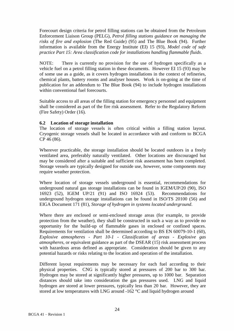
6.2 Location of storage installation
The location of storage vessels is often critical within a filling station layout.
Cryogenic storage vessels shall be located in accordance with and conform to BCGA
CP 46 (86).
Wherever practicable, the storage installation should be located outdoors in a freely
ventilated area, preferably naturally ventilated. Other locations are discouraged but
may be considered after a suitable and sufficient risk assessment has been completed.
Storage vessels are typically designed for outside use, however, some components may
require weather protection.
Where location of storage vessels underground is essential, recommendations for
underground natural gas storage installations can be found in IGEM/UP/20 (90), ISO
16923 (52), IGEM UP/21 (91) and ISO 16924 (53). Recommendations for
underground hydrogen storage installations can be found in ISO/TS 20100 (56) and
EIGA Document 171 (81), Storage of hydrogen in systems located underground.
Where there are enclosed or semi-enclosed storage areas (for example, to provide
protection from the weather), they shall be constructed in such a way as to provide no
opportunity for the build-up of flammable gases in enclosed or confined spaces.
Requirements for ventilation shall be determined according to BS EN 60079-10-1 (60),
Explosive atmospheres - Part 10-1 - Classification of areas - Explosive gas
atmospheres, or equivalent guidance as part of the DSEAR (15) risk assessment process
with hazardous areas defined as appropriate. Consideration should be given to any
potential hazards or risks relating to the location and operation of the installation.
Different layout requirements may be necessary for each fuel according to their
physical properties. CNG is typically stored at pressures of 200 bar to 300 bar.
Hydrogen may be stored at significantly higher pressures, up to 1000 bar. Separation
distances should take into consideration the gas pressures used. LNG and liquid
hydrogen are stored at lower pressures, typically less than 20 bar. However, they are
stored at low temperatures with LNG around -162 °C and liquid hydrogen around

25 BCGA 41 – Revision 1
-253 °C. Filling stations for cryogenic gases require unique layout considerations to
allow for the management of released vapour. The layout and design should consider
the effects of a release of a cryogenic liquid, such that any release can rapidly evaporate
and will have only a minimum effect on the storage tank supporting structure, such that
the storage tank will remain adequately supported.
This requirement, location, efficiency and access to connecting pipework shall be
considered during the early stages of concept design, refer to Section 6.5.
Gaseous hydrogen bulk storage installations shall conform to BCGA CP 33 (83).
Further information on compressed hydrogen storage can be found in NFPA 2 (100)
and NFPA 55 (102), Compressed gases and cryogenic fluids code, also ISO/TS 20100
(56).
LNG bulk storage installations shall conform to BCGA 46 (86). Further guidance is
available in IGEM UP/21 (91) and ISO 16924 (53).
Further guidelines for general practice can be found in EIGA Document 114 (79),
Operation of static cryogenic vessels, and BS EN ISO 21009-2 (57), Cryogenic vessels.
Static vacuum insulated vessels. Operational requirements.
Specific recommendations for liquid hydrogen storage can be found in EIGA
Document 6 (74). Further information for liquid hydrogen storage can be found in
NFPA 2 (100), NFPA 55 (102) and ISO/TS 20100 (56).
Specific recommendations for LNG storage installations can be found in BS EN 13645
(43). Further information for LNG storage installations can be found in IGEM/UP/21
(91), ISO 16924 (53), BCGA CP 46 (86) and NFPA 52 (101).
Physical separation of the storage installation from exposures or sources of hazard shall
be enforced to minimise the consequences of minor incidents. Consideration shall be
given to hazards arising from both flammable atmospheres and heat flux following
ignition. Consideration shall also be given to the method of delivery of fuel to the
storage installation. The DSEAR (15) risk assessment shall cover all hazards that may
arise during the delivery of fuel, and any additional control measures that may be
required during this period. Where necessary, guidance on vehicle impact protection is
included in Section 6.4. Consideration should also be given to impact avoidance for the
road tanker or mobile gaseous fuel trailer during offloading, and when the tanker or
trailer is parked (e.g. by using cones or possibly barriers). Vehicle refuelling whilst the
tanker or trailer is offloading should be justified by a suitable risk assessment. The
arrangements for delivery of fuels should be considered at an early stage, as this could
significantly increase the inventory at a site albeit it for a short period, and could
influence other aspects of the installation design (e.g. its floor -plan).
The separation distances in this document are intended as a guideline for both planning
authorities and system designers and installers. They are the minimum recommended
separation distances based upon generic considerations, which reflect both UK and
worldwide industry experience on design and installation of liquefied and compressed
flammable gas operations. It is the duty of the designer to ensure a comprehensive

26 BCGA 41 – Revision 1
viewpoint is given to separation distances at multi-fuel stations, including the differing
requirements for high-pressure ambient gaseous fuels and cryogenic liquid fuels.
Recommended minimum separation distances for hydrogen storage installations are
presented in Appendix 1. Where appropriate, these separation distances should be
applied both vertically and horizontally.
Recommended minimum separation distances for CNG and/or LNG storage
installations are presented in Appendix 2.
Based upon the details of a given installation it may be acceptable to reduce the
separation distances relative to those detailed in this document. Any reductions should
be justified based upon a site-specific risk assessment, or through the use of fire risk
modelling or standard mitigation factors (refer to the Blue Book (94) and relevant
industry documents).
The risk assessment shall specifically address the nature and use of adjacent property.
Recommended minimum separation distances may be extended where higher risks are
identified, for instance:
where the site is close to a heavily populated area;
where the site is close to a vulnerable population: school, hospital etc.;
where the site is remote from external help (such as the fire authority).
where existing site conditions may foreseeably change on either a
temporary or permanent basis, i.e. change of use, future planning considerations,
increased personnel or maintenance activities.
If a bespoke safety case is required, guidance on a number of different methodologies
that exist for the determination of recommended minimum separation distances can be
found in EIGA Document 75 (78), Determination of safety distances, NFPA 2 (100)
and ISO/TS 20100 (56). It should be noted however that these methodologies may give
distances that are not consistent with the minimum separation distances recommended
by the BCGA.
In the event of a spill of a liquefied fuel gas, the liquid will both rapidly evaporate and
travel until it settles at the lowest point (before full evaporation). It is important to
ensure containment of the spill above ground in an area remote from personnel, where
the liquid can evaporate safely without presenting a risk of asphyxiation, cold burns,
ignition, or thermal shock to mechanical components. Vapour clouds which fail to
quickly disperse may be blown by the wind and in some circumstances may have a
potential to blow far beyond the site with a potential risk of asphyxiation or ignition.
Where liquefied fuel gas leaks may have entered confined spaces, appropriate measures
should be taken before personnel entry in accordance with the Confined Space
Regulations (8). The actions to be taken in the event of a spill should be clearly
identified, trained for, and included in the emergency response procedure, refer to
Section 14.

27 BCGA 41 – Revision 1
Consideration should be given to the appropriate use of civil engineering features for
risk mitigation, for example diversion kerbs or grading, to ensure that liquid leakage
from any adjacent hazardous store is prevented from accumulating in undesirable
locations (e.g. within the fuel gas store). When liquefied fuel gas storage is present,
measures should be employed to prevent spilled liquid fuel gas from flowing onto the
forecourt, onto cold-sensitive components (e.g. non-cryogenic rated storage vessel
support legs or skirts), into public areas or in the vicinity of other features, for example
drains, manholes, culverts, etc. which might lead to the creation of a hazard elsewhere,
in certain circumstances. The design and construction of the station base should allow
for the safe dispersal (e.g. evaporation) of liquid leakage. Options such as boil-off
pads, sloped surfaces, pits, walls, bunds etc. may be considered in this respect, noting
that other hazards may thereby be introduced and so any such proposal should be
validated by risk assessment. Further guidance is contained in BCGA CP 46 (86).
Where appropriate, storage areas shall be designed to be readily accessible to mobile
supply equipment, refer to Section 3.3 and to mobile service and safety equipment.
The liquid storage installation shall meet the requirements of BCGA CP 46 (86).
Fencing, civil engineering and general provisions for non-liquid installations shall
follow the same principles (such as buffer stores, compressor houses, etc).
The minimum recommended separation distances of Appendix 1 and Appendix 2 shall
apply regardless of the position of the barrier or fence. If a fire resistant wall is used,
then by the methodology outlined in BCGA CP 4 (82), the safety distance may be
measured as the shortest distance around the ends of the wall to the storage installation.
An important principle in the hazardous area classification is the availability of
sufficient ventilation. The effect of firewalls can be to reduce ventilation, and this
should be considered in the site risk assessments. Firewalls shall provide a minimum of
30 minutes fire resistance in respect of integrity, insulation, and where applicable load
bearing capacity. Where the wall separates vulnerable populations from the dangerous
substance, the fire resistance provided shall be for a minimum of 60 minutes. Fire tests
are covered in BS 476 (33), Fire tests on building materials and structures.
If the storage area contains individual and / or bundles of cylinders, the layout shall be
designed to allow the use of suitable manual handling equipment and as appropriate,
forklift trucks.
Site areas where installations used for the production, storage and dispensing of
flammable liquids and gases and areas used for the delivery of fuels, shall not be
located beneath overhead electrical power lines. Installations shall be sited so that
damage to the installations or delivery vehicles by electric arcing from overhead or
other cables cannot occur.
6.3 Access and egress for fuel delivery vehicles
Access and egress may be required for delivery vehicles. For cryogenic flammable
fluids refer to BCGA CP 46 (86). Points for consideration include:
(i) Protection of the tank(s) and pipes from vehicle impact, for example by
barriers, bollards or kerbs. Guidance on vehicle impact protection is included in
Section 6.4;

28 BCGA 41 – Revision 1
(ii) Avoiding wherever possible the requirements for delivery vehicles to
reverse;
(iii) Emergency arrangements for delivery vehicles and the delivery team; for
example, requirements for the vehicle being able to drive away in a forward
direction without complex manoeuvring in the event of an emergency, subject to
the anti-drive-away provisions that should apply;
(iv) Hose lengths and hose handling arrangements; for example, parking post,
storage space, purging, weather protection, capping, etc.;
(v) Demarcation of the delivery vehicle parking location;
(vi) Signage, lighting and surface condition;
(vii) Drainage and spill arrangements from the delivery area;
(viii) The construction of the delivery pad surface, taking account of the actual
delivery vehicle weight, size and layout;
(ix) Space (including height clearance) for use of cranes, fork-lift trucks or other
accessories when making deliveries; for example, bundles of cylinders;
(x) Restriction of access to the tanker stand when deliveries are being made;
(xi) Restriction of access to the tanker stand when deliveries are not being
made;
(xii) Line-of-sight maintenance from vehicle control position to tank gauges and
indicators;
(xiii) Line-of-sight maintenance from station control position to the tanker stand;
(xiv) The position of any sensors, alarms, alarm repeaters, indicators etc. for the
use of the delivery team including the on-site competent person;
(xv) Electrical earthing and equi-potential bonding facilities (and any necessary
signage and instructions);
(xvi) Supply of nitrogen or dry air for road tanker discharge operation. Where
relevant refer to BCGA CP 44 (85), The storage of gas cylinders.
(xvii) Special site rules which may need to apply during (and immediately
before and after) deliveries;
(xviii) The impact on the site zoning under DSEAR (15);
(xix) Security (such as measures to prevent unauthorised removal of the road
tanker or trailer from the stand, i.e. to prevent theft);

29 BCGA 41 – Revision 1
(xx) Anti-drive-away provisions, to prevent damage to the installation
(including hoses) in the event of tanker drive-away.
During fuel delivery, the tanker stand should be designed and managed exclusively for
that purpose. If the delivery operation cannot be contained within a secured area,
temporary demarcation and/or other reasonable means (e.g. cones) should be
considered to restrict public access during the delivery process.
At stations where multiple fuels are stored or dispensed, simultaneous bulk deliveries of
differing fuels should be prevented unless a suitable risk assessment determines
otherwise. Further information on the delivery requirements of other fuels is detailed in
The Blue Book (94).
HSE L133 (70), Unloading petrol from tankers. DSEAR. Approved Code of Practice
and guidance, whilst prepared for the delivery of petroleum products to filling stations,
contains relevant transferable information on principles appropriate to the risk
assessment and safe delivery of fuels to filling stations.
6.4 Location and installation of dispensing points
A specific area should be defined for vehicle fuelling. Wherever practicable,
dispensing equipment should be located outdoors in a freely ventilated area. Indoor
locations may only be considered after a suitable and sufficient risk assessment has
been completed. Further guidance for indoor hydrogen vehicle filling can be found in
NFPA 2 (100).
The location and proximity of dispensing equipment shall be established by risk
assessment. Based upon the details of a given installation it may be appropriate to
propose increased or reduced minimum separation distances relative to those detailed in
this document. Any reductions should be justified by, for example, the use of fire risk
and gas dispersion modelling or standard mitigation factors (refer to the Blue Book (94)
and other relevant industry documents). The minimum separation distances within
BCGA CP 4 (82) are recommended for the dispensing of gaseous hydrogen. Once
established, minimum separation distances and hazardous zone requirements for
additional dispensers and equipment shall be observed. For the minimum
recommended separation distances refer to Appendix 1 and Appendix 2.
Specialist storage and dispensing requirements for LNG shall be taken into
consideration when carrying out the risk assessment.
Where multiple dispensers are installed, e.g. for simultaneous refuelling, consideration
shall be given to the position of the dispensers and their proximity to planned or
existing dispensing equipment, storage and buildings, occupied and unoccupied.
When determining the location and positioning of dispensers consideration should be
given to traffic flow restrictions, traffic movements in the immediate vicinity of the
station, and the size and length of the vehicles to be refuelled. Measures to prevent
dangerous manoeuvres, for example, reversing into the path of traffic should be taken
when considering the design of the station and the location of dispensing points.

30 BCGA 41 – Revision 1
The vehicle fuelling area should be level, except for a minimal slope to aid surface
drainage.
Physical protection shall be provided to protect the dispenser from vehicular impact.
The characteristics of the specific vehicles to be fuelled at the installation should be
used to determine the civil engineering feature dimensions.
Height above the road
surface
Clearance between
dispenser and the edge of
the plinth
Stations serving light passenger
vehicles only 120 mm 200 mm
Stations serving heavy goods
and passenger-service vehicles 415 mm 500 mm
Table 3 – Typical dimensions for dispenser plinths
Dispensers shall be mounted on a plinth (or ‘island’) unless alternative physical
protection is employed. Table 3 provides guidance on typical dimensions for dispenser
plinths. The dimensions in Table 3 take into consideration the large diameter wheels of
Heavy Goods Vehicles (HGV) or Public Service Vehicles (PSV) and the typical vehicle
overhang. If a station is being designed with specific vehicle types in mind, it may be
possible to establish exact vehicle dimensions and hence design the station and plinth
for those vehicles. Alternatively, suitable protection shall be provided to prevent
mechanical damage to all parts of the installation and associated pipework, for example
by the use of crash barriers or bollards. The type of vehicle expected to use the filling
station should be considered when specifying physical protection measures. Physical
protection arrangements for commercial vehicle filling may need to be more robust,
larger and with greater clearances than for light passenger vehicles.
Plinths should typically be of reinforced concrete construction, with suitable kerbs.
Vehicle restraints are covered in BS 7669 (38), Part 3, Vehicle restraint systems. Guide
to the installation, inspection and repair of safety fences.
Dispensers and associated equipment may be housed in enclosures. Such enclosures
may change the extent of the DSEAR (15) hazardous area. This may assist in the siting
of electrical equipment, refer to Section 3. However, this advantage may be at the
expense of the potentially explosive area within the enclosure, hence classification
inside the enclosure or housing shall be carried out, and appropriate electrical devices
installed, refer to Section 7.1.
As with other areas of the filling station, where new or existing electrical equipment is
within the hazardous area surrounding dispensing equipment, this equipment shall be
rated for the appropriate gas group(s), for example, group IIC for hydrogen.
If a canopy is provided over the dispensing area, refer to Section 7.9.

31 BCGA 41 – Revision 1
All electrical devices or lighting mounted within hazardous areas above the dispenser
shall be appropriately classified. Where the accumulation of flammable gas or vapour
cannot be avoided, the inclusion of gas detection equipment should be considered. The
gas detection system should automatically stop filling operations and render the
installation safe, in the event of gas detection. Refer to Section 7.1.
Dispensers shall be secured against unauthorised use and access control measures
should be considered, for example, swipe card readers. The fuel gas supply to the
dispenser shall be capable of being isolated. To prevent unauthorised or inadvertent re-
activation of isolated services it is strongly recommended that the isolation point is in a
secure location. Where the isolation point is in an area accessible to the public or
unauthorised parties outside operating hours, it shall be fitted with appropriate security
devices.
6.5 Connecting pipework
Manifolds and fuel gas distribution pipework shall comply with the requirements of
BCGA CP 4 (82). CNG installation connections to gas supply network pipework and
manifolds shall conform to the requirements of IGEM UP/20 (90). Further guidance
for CNG storage as part of a vehicle filling station can be found in ISO 16923 (52) and
NFPA 52 (101). The material of construction shall be compatible with the gas,
pressure and temperature.
Wherever practicable, the connecting pipework between production, storage and
dispensing equipment should be located in the open air. Where dispensers (especially
for cryogenic services) are located on remote dispenser islands pipework should be laid
in suitably constructed ducts.
All pipework shall be accessible to facilitate periodic inspection, examination and/or
testing.
Where there is a requirement to maintain the product as a cryogenic liquid then
pipework should be insulated, for example vacuum insulated, and kept as short and as
straight as is reasonably practical. This will assist in minimising boil-off.
Pipework should be marked with the pipe contents, and if possible the flow direction
and pressure and be colour coded. Where pipework is protected by insulation materials
then the identification markings are to be on the outside of the insulation.
6.6 On site fuel generation equipment and related process equipment
Fuel generation equipment shall be installed and operated according to the
manufacturer’s recommendations.
The equipment may have to be kept at ambient temperatures but above freezing
conditions, a degree of protective enclosure may be necessary. If the equipment is fully
enclosed requirements for explosion relief shall be considered as part of the risk
assessment.
Access is to be restricted to authorised personnel.

32 BCGA 41 – Revision 1
6.7 Vent systems
All gaseous fuels within the scope of this code are stored and used under pressure. As
such they are fitted with over pressure protection devices to release excess pressure
under normal operating conditions and in emergency situations such as fire. Manually
operated valves may also be fitted to release pressure, for example, for maintenance.
When these devices operate any product that is subsequently vented shall be dispersed
safely to reduce the risk of accumulation, ignition, or impingement on personnel,
equipment and buildings. This shall be achieved by the use of a vent system where the
product is released via a remote vent stack.
For information on the design, installation and marking of vent stacks installed for
cryogenic flammable fluids refer to BCGA CP 46 (86).
6.8 Vent recovery
Consideration shall be given to vent recovery and the prevention of boil-off gas
escaping from LNG vehicles and static equipment during the refuelling process, for
example, through the use of vapour recovery or vapour management equipment. Refer
to ISO 16924 (53).
6.9 Other filling station activities
Consideration should be given to the layout of the filling station with relation to
vehicular and pedestrian movements arising from all other foreseeable filling station
activities, for example, petrol / diesel / LPG dispensing and deliveries, shop, tyre
inflation, car wash, customer parking etc. As far as is reasonably practicable, activities
unrelated to vehicle filling should be located outside of hazardous areas and vehicles
and pedestrians should not have to pass through hazardous areas to get to those
activities. The recommended minimum separation distances should be maintained.
Access requirements for personnel, plant and equipment shall be taken into
consideration for operational, maintenance, inspection, testing and decommissioning
activities.
Large vehicles should not have to perform complex manoeuvres and the site should be
designed and laid-out to facilitate this. An awareness should be maintained of
pedestrian movements around the installation, in order that hazards (for example, due to
driver’s blind-spots) may be minimised.
7. DESIGN OF FILLING STATION
7.1 General
The filling station shall be designed to minimise risk to users, operating personnel,
general public, nearby properties and the environment. This is referred to as safety by
design; a concept which incorporates fail-safe mechanisms, features and philosophy.
Commonly, potential methods of failure, the associated consequences and mitigating
safeguards are explored through a combination of risk identification and assessment
methodologies including DSEAR (15) risk assessments, Hazard and Operability
Studies (HazOpS or HAZOPS), Failure Mode and Effect Analysis (FMEA) and Layer
of Protection Analysis (LOPA). Where in-scope safety instrumented systems are

33 BCGA 41 – Revision 1
present, consideration shall be given to applying Safety Instrumented System (SIL)
techniques in accordance with BS EN 61511 (63), Functional safety. Safety
instrumented systems for the process industry sector. Specific and more detailed
information can be obtained from BS EN 61508 (62), Functional safety of electrical /
electronic programmable electronic safety related systems.
Designers engaged and involved in the outline definition, detailed design, specification,
installation and commissioning of installations in the scope of this document shall be
suitably competent and shall have experience in the relevant field(s). Table 4 provides
a guide to the competence requirements for Designers of specific types of installation:
Fuel
Storage
Competence and experience required in the fields of:
Compressed
gases Liquefied
cryogenic
gases
Flammables
including
ATEX/DSEAR
Pressure
systems
engineering
Fuel
dispense
equipment
Hydrogen
(gaseous) Y
N (unless liquid
is present) Y Y Y
Hydrogen
(liquefied) Y Y Y Y
Y (if in scope)
CNG Y N
(unless liquid
is present)
LNG Y Y
Table 4: Competence and experience guide
The appropriate level of reliability of control and safety systems should be determined
through appropriate analysis and suitable risk assessment.
The installation shall have appropriate automated safety shutdown and isolation
capabilities and easily accessible manual emergency shutdown devices. For LNG
automated shutdown and isolation capabilities refer to ISO 16924 (53). Due regard
shall be given to the combination of shutdown and isolation functions for all other
hazardous products, systems and services on the filling station site, including
appropriately positioned emergency switching devices in accordance with the Blue
Book (94). Safety circuitry should be hard wired using suitable latching relays or via a
safety validated BS EN 61508 (62) compliant computer control system(s).
The design shall comply with DSEAR (15) (taking into account fuel buoyancy), the
PSSR (12) and, where appropriate, shall be CE marked to the relevant applicable
European Directives, such as:
The Pressure Equipment Directive, European Directive 2014/68/EC (PED)
(28), implemented in the UK through the Pressure Equipment Regulations (10);

34 BCGA 41 – Revision 1
The Machinery Directive, European Directive 2006/42/EC (24);
The Low Voltage Directive, European Directive 2014/35/EC (27);
The Electromagnetic Compatibility Directive, European Directive
2014/30/EC (26);
DSEAR (15) / ATEX European Directive 99/92/EC (23);
Directive 2009/104/EC (30) the Use of Work Equipment Directive for
minimum health and safety requirements for the use of work equipment by
workers at work, implemented in the UK through the PUWER Regulations (9).
The design shall protect against hazards associated with loss of containment of fuel.
The designer should typically consider the following:
Minimising the number of potential release points and reducing the
likelihood of release.
Ventilation to maximise dilution of leaked fuel, hence keeping any resulting
mixtures below flammable limits and avoiding the build-up of potentially
explosive atmospheres or the risk of asphyxiation in confined spaces. Refer to
the Confined Spaces Regulations (8).
Fuel leak detection, refer to:
BS EN 60079 (60) Part 29, 1 to 4, Explosive atmospheres. Gas
detectors;
Hydrogen sensing BS ISO 26142 (59), Hydrogen detection
apparatus. Stationary applications);
Use of LNG low temperature sensors, ISO 16924 (53) to indicate
product loss.
Emergency shutdown system(s), as appropriate.
Hazardous area classification including of potential leak points, vents (and
any hazards arising from these vents) and drains.
Ignition protection, earthing and bonding to prevent static (and other)
charge build-up.
Mitigation against the effects of ignition, for instance blast walls, explosion
relief, fire protection and lightning protection (refer to BS EN 62305 (64),
Protection against lightning).

35 BCGA 41 – Revision 1
A major concern associated with the storage and dispensing of all vehicle fuels is the
risk of fire and explosion. Both electrical and mechanical equipment can be a source of
ignition.
The probability of a fire and explosion hazard is reduced by the provision of good
design and layout, as well as appropriate operating and maintenance procedures.
Generally there are two elements to fire risk assessment. The first is the special,
technical and organisational measures which, in respect of fuel stations, are essentially
the precautions required to prevent the outbreak and rapid spread of a fire or explosion
due to work activities concerning the receipt, storage and dispensing of vehicle fuels.
Secondly, appropriate measures need to be taken to address ‘everyday’ or general fire
risks. These include those measures necessary to prevent fire and restrict its spread and
those measures necessary in the event of outbreak of fire, to enable those present
(including the general public) to safely evacuate the premises.
These general fire precautions include the means for detecting fire and giving fire
warning, the means for fire-fighting, the means of escape, ensuring escape routes can
be used safely and effectively by employees and members of the public visiting the site,
and the competence of employees in fire safety. The presence of a variety of different
fuel types, comprising a blend of flammable components with differing properties
including those soluble in water, may influence the form and consequences of any fire
and therefore the required range of the general fire precautions. It is of critical
importance that the presence of dangerous substances is taken into account in
determining the general fire precautions necessary. A fire risk assessment shall be
carried out in accordance with the Regulatory Reform (Fire Safety) Order (16). Fire
protection equipment shall be provided as required by the site fire risk assessment.
Special consideration shall be given for hydrogen installations and high purity natural
gas (LNG and CNG) installations, in respect of their rare propensity to burn with a
flame which is (in daylight) undetectable by eye. Fires may therefore be difficult, if not
impossible, to detect in the traditional and very obvious manner that applies for most
other combustible materials.
Other flammable substances and combustible materials shall not be stored or be
allowed to accumulate in the vicinity of the storage or dispensing areas.
Electrical installations shall as a minimum, conform to BS EN 7671 (39), Requirements
for electrical installations. IET wiring regulations.
All fixed electrical equipment located in hazardous zones shall have the appropriate
ATEX rating, refer to BS EN 60079 (60), Explosive atmospheres. Part 14, Electrical
installations design, selection and erection, taking into account the relevant gas group(s)
classification.
Where gaseous fuels and traditional fuels are dispensed at the same filling station,
mandatory requirements for electrical installations are detailed in The Blue Book (94).
Where applicable, electrical equipment which is necessary for the installation shall be to
BS EN 60529 (61), Specification for degrees of protection provided by enclosures,

36 BCGA 41 – Revision 1
protection class IP54 or better. For more severe environmental conditions protection
class IP55 (designed to protect against water jets) should be used.
Lightning protection may be necessary to comply with local conditions or site
regulations. Lightning protection should be considered and implemented as
appropriate, refer to BS EN 62305 (64).
Conductive parts (e.g. metal fitments) on the installation including fencing, gates,
tanks and all pipework, vent stacks and vent recovery hoses, shall be adequately equi-
potential (earth) bonded. Refer to BS 7430 (37), Code of practice for protective
earthing of electrical installations.
Where gas detection is identified as necessary within the risk assessment, a suitable gas
detection system is to be fitted. For information on gas detectors refer to BS EN 60079
(60), Explosive atmospheres – Part 29-2: Gas detectors – Selection, installation, use
and maintenance of detectors for flammable gases and oxygen.
The locations for the gas detection equipment shall take into account the physical
properties of the respective gases, potential release points and areas where they may
accumulate.
Audio / visual alarms, along with appropriate warning notices, safety signs and
instructions, shall be positioned at strategic locations within the area and at control
centres, as determined by the risk assessment. Alarm levels are to be set to allow action
to be taken in the event of a release of product, providing an early warning system, but
not such that it creates false alarms. Thus allowing time for personnel to evacuate the
area before hazardous conditions are reached i.e. flammability range and/or workplace
exposure limits are reached.
Detection equipment should be installed, maintained and tested in accordance with the
manufacturer’s recommendations. Alarms should be tested regularly.
All systems should be fail safe and programmable devices should have an appropriate
SIL (Safety Integrity Level) rating. The gas detection system and/or any process
control system, may interface with the emergency shut-down system.
Adequate lighting shall be provided to allow for the identification of the product(s)
(signage and labels), to allow normal operations, maintenance, manual handling
activities and deliveries to be undertaken safely, as well as to assist with security. The
light source used shall give suitable colour rendering to enable colour labelling to be
easily recognised by persons with normal colour vision. Lighting is required to be
appropriately located, lighting equipment and ancillaries shall be suitably rated for the
hazardous area (if any) in which it is located. The location of any lights should take
into account vent outlets and potential release points, these are to be avoided. Where
required, emergency lighting shall be to the requirements of BS 5266 (35), Emergency
lighting. Code of practice for the emergency escape lighting of premises.
The design of the overall system shall allow for routine and emergency shutdown.
Consideration should be given to the requirements for shutdown systems, depending on
the safety critical nature of the shutdown. The installation shall incorporate isolation

37 BCGA 41 – Revision 1
valves to enable the execution of routine and emergency shutdowns. A summary of
requirements is presented in Table 5.
The location of Emergency Shutdown Devices (ESDs) should be determined according
to the safety requirements of the filling station equipment. The function of ESDs may
differ according to the location requirements. Requirements for separate process and
emergency isolation valves should be established by risk assessment.
Unless specifically determined otherwise the installation shall be designed for operation
in an ambient UK temperature range of -20 °C to +40 °C, but shall take into account the
appropriate process temperatures. LNG and liquid hydrogen equipment shall be
designed for operation at the appropriate cryogenic temperatures.
Guidance on emergency procedures is included in Section 14.
The following definitions relate to Table 5:
Routine shutdown. Following the completion of an intended normal
function of the system; for example, when the desired quantity of gas has been
transferred, or when the maximum pressure has been achieved. This is equally
appropriate to the gas storage system as to the gas dispensing system.
Extended routine shutdown. This may take place where only supervised
filling is permitted, for instance overnight. In the absence of a supervisor, the
dispenser may be locked physically or using a password protected lock-out to
prevent unauthorised filling.
Emergency shutdown. On detection of an abnormal condition in the
system; for example, when the maximum fill pressure has been exceeded due to
failure of the routine shutdown, or other alarms appropriate to the system. This
includes activation of manual emergency stop devices. Consideration should be
given to the different instigators of an emergency stop, and whether an
emergency shutdown due to an abnormal condition need only isolate a single
dispenser, or should instigate a more comprehensive shutdown, potentially
including other filling activities.
Maintenance shutdown. In order to carry out maintenance safely, the
equipment shall be capable of being put into a safe state. This may include
isolation of the storage vessels, or venting the storage tanks as appropriate to the
work being carried out. Purging should be carried out prior to putting the system
back into operation where appropriate, and covered by the appropriate
maintenance procedure.
Non-public access filling. Where filling stations are to be used by
specialist personnel only, for example captive fleets. The requirements for risk
management of the automation of the filling operation should be determined by
risk assessment.

38 BCGA 41 – Revision 1
Type of station Characteristics of shutdown recommended
Man
ned
op
erati
on
an
d n
on
-pu
bli
c
acc
ess
fill
ing
Un
man
ned
op
erati
on
or
pu
bli
c
acc
ess
/ n
on
sp
ecia
list
fil
lin
g
Tim
e cr
itic
al
/ fa
st a
ctin
g
Dep
ress
uri
se /
ven
t d
isp
ensi
ng
lin
es
Pro
cess
iso
lati
on
of
dis
pen
ser
from
gas
sou
rce
Em
ergen
cy i
sola
tion
, in
clu
din
g
stora
ge
sub
-set
s
Rem
ote
ala
rm
Res
et b
y a
uth
ori
sed
per
son
nel
on
ly r
equ
ired
Routine
shutdown -
Automated 3 1 1
Routine
shutdown -
Manual 2 3 1
Extended
routine
shutdown 3 1 1 3 1
Emergency
shutdown -
Manually
initiated NOTE 1
1 1 1 2 1 1 1 1
Emergency
shutdown -
Automatically
initiated NOTE 2
1 1 1 2
NOTE 3 1 1 1 1
Maintenance
shutdown 1 1 3 3 3
1 = Essential
2 = Recommended
3 = Optional
NOTES:
1. Manual initiator may be remote, including emergency switching devices.
2. Mechanical measures to prevent over-pressurisation should be included in the
dispensing line, regardless of whether the emergency shutdown is initiated manually
or automatically.
3. Generally not required for CNG and LNG systems.
Table 5: Recommendations for the requirements for shutdown systems

39 BCGA 41 – Revision 1
Public access filling. Where filling stations are intended or could
reasonably be expected to be used by non-specialist personnel, including the
general public, the filling operation and emergency shutdown functionality should
be provided by automated process control.
Remote monitoring. When considering the implementation of remote
control systems, including voice-activated telematics, a suitable risk assessment
shall be carried out.
7.2 Fuel gas storage and process equipment
Compressed hydrogen gas storage systems shall conform to the requirements of BCGA
CP 4 (82) or BCGA CP 33 (83), depending on the storage installation. Liquid
hydrogen storage shall conform to the requirements of BCGA CP 46 (86). Further
guidance for the safe design of liquid hydrogen storage can be found in EIGA
Document 6 (74). Further guidance for the safe design of hydrogen installations
including compressors, buffer storage and related equipment can be found in NFPA 2
(100) and ISO/TS 20100 (56).
Guidance for the safe design of CNG installations including compressors, buffer
storage and related equipment as part of a vehicle filling station can be found in IGEM
UP/20 (90), ISO 16923 (52). Further information can be found in NFPA 52 (101).
Specific recommendations for LNG storage installations and related equipment can be
found in BS EN 13645 (43). Further information can be found in BCGA CP 46 (86),
IGEM/UP/21 (91), ISO 16924 (53) and NFPA 52 (101). This guidance may apply to
the liquid storage elements of a CNG installation.
Wherever possible hydrogen, CNG and LNG storage and related equipment should be
located above ground, in the open air, in a well-ventilated area. If it is necessary to
store hydrogen underground, recommendations for underground installations can be
found in ISO/TS 20100 (56) and EIGA Document 171 (81). LNG underground storage
recommendations can be found in ISO 16924 (53). Where there are enclosed or
partially enclosed storage areas (for example, that provide protection from the weather),
they shall be constructed in such a way as to:
Provide no opportunity for the potentially hazardous build-up of flammable
gas mixtures or flammable gases in enclosed spaces.
Provide adequate explosion relief. In the case of hydrogen and LNG avoid
the risk of transition of any leak followed by fire from deflagration to detonation.
The use of very light wall construction is recommended; this is likely to be non-
metallic. Refer to BCGA CP 33 (83), further information can be found in NFPA
2 (100) and for LNG in ISO 16924 (53).
Where gaseous equipment is provided in a modular form, such as being
located in an ISO container, then it is recommended that the ISO container is of
open frame construction, has any necessary weather protection and meets the
requirements above.

40 BCGA 41 – Revision 1
Where CNG and LNG equipment is provided in a modular form, such as a
tube trailer or mobile station, for CNG refer to IGEM UP/20 (90) and ISO 16923
(52), and for LNG refer to IGEM UP/21 (91) and ISO 16924 (53).
Consideration should be given to any potential hazards or risks relating to the location
and operation of the installation.
Fuel degradation in storage shall be considered when determining the size of storage
containment. Design shall, where practical, include measures to promote a longer
storage life, for example, the reduction of heat gain and boil-off.
Additional guidance for general practice in the design of liquefied flammable gas
storage can be found in EIGA Document 114 (79) and BS EN ISO 21009-2 (57).
Permanent vacuum gauges (to monitor the condition of the cryogenic tank vacuum) are
not recommended. In the UK cryogenics industry, it is not standard practice to fit
vacuum gauges - this applies to all services, not just fuel gases. Vacuum gauges and
their pipefittings constitute an additional series of leak-prone connections for the
interspace vacuum (i.e. their presence makes the vacuum less reliable). In addition,
'soft' or collapsed vacuums are more readily detected in practice by normal operational
checks, such as observing the formation of ice patches on the vessel outer jacket or
through excessive venting from the relief valves, rather than by gauges. Soft and/or
collapsed vacuums are rarely if ever safety critical.
Isolation valves closed by the emergency shutdown system should be located as close
as practicable to the storage system and preferably within a secure area to prevent
unauthorised operation or tampering. Where numerous storage vessels are used,
consideration should be given to separating these into isolatable sub-groups. ESDs
activating these isolation valves shall be provided both locally at each exit point from
the storage site and remotely.
Guidance on the safe design of on-site hydrogen generation equipment can be found in
BS ISO 16110-1 (49), Hydrogen generators using fuel processing technologies. Safety.
and BS ISO 22734-1 (58), Hydrogen generators using water electrolysis process.
Industrial and commercial applications.
Further guidance can be found in the HSE research report RR715 (73), Installation
permitting guidance for hydrogen and fuel cell stationary applications: UK version,
which provides a structured analysis of known documents relevant for permitting
hydrogen and fuel cell systems in the UK, and suggests best practice for the installation
of different generic types of hydrogen and fuel cell systems.
Appropriate warning notices, safety signs and instructions shall be displayed. Refer to:
COMAH Regulations (19).
The Health and Safety (Safety Signs and Signals) Regulations (7).
BS EN ISO 7010 (36), Graphical symbols. Safety colours and safety signs.
Registered safety signs.

41 BCGA 41 – Revision 1
When mounting signage and notices, due regard shall be paid to the security
requirements of the installation.
If there is a risk of an explosive atmosphere identified from the DSEAR (15) risk
assessment then appropriate demarcation and / or signage shall be provided at the
boundary of the zoned area. Refer to Figure 3.
Subject to the notes above, notices shall be positioned so that they are visible from all
sides of approach to the installation. They should typically be positioned at or on the
security fence for the installation. The following should be considered:
FLAMMABLE GAS
NO SMOKING
NO NAKED FLAMES
NO MOBILE PHONES OR OTHER ELECTRONIC DEVICES
These signs shall be supplemented by a flammable material warning triangle. Refer to
Figure 3.
It is recommended that the storage tank is labelled with the appropriate UN number(s)
as defined in the United Nations Recommendations on the Transport of Dangerous
Goods, Model Regulations (32). A diamond hazard label may be displayed.
The United Nations Recommendations on the Transport of Dangerous Goods, Model
Regulations (32) designations for the products covered by this code of practice are:
Hydrogen – UN 1049, HYDROGEN COMPRESSED.
CNG – UN 1971, NATURAL GAS, COMPRESSED with high methane
content.
LNG – UN 1972, NATURAL GAS, REFRIGERATED LIQUID with high
methane content.
A pictogram should be used instead of written notices wherever possible. For examples
refer to Figure 3.
A sign shall be displayed showing:
(a) Actions to take in the event of an emergency, for example a gas leak or fire.
Refer to Figure 4.
(b) The site operator’s routine contact details.
(c) Emergency contact information including an emergency phone number, for
example of the gas supplier and/or the site operator.

42 BCGA 41 – Revision 1
(d) The emergency services phone number.
This information should also be available at a control point, for example, the site
control room, site security.
Potential
Asphyxiating
Atmosphere
Cryogenic Liquid Flammable
Gas
Explosive
Atmosphere
No source of
ignition
No Smoking No Unauthorised
Access
No mobile phones
Figure 3: Example warning notices and safety signs
Figure 4: Example notice for emergency actions
7.3 LNG vapouriser
A vapouriser (usually ambient) adds heat energy to LNG which converts it into a
vapour state, for example, producing CNG in an LCNG station. Vapourisers are
classified as pressure vessels or pipelines and shall conform to the appropriate design
codes and standards, for example, Pressure Equipment Regulations (10) and PSSR (12),
BS EN 13458 Parts 1 and 2 (42) . Refer to IGEM UP/21 (91) and ISO 16924 (53).
The vapouriser design typically uses ambient atmospheric temperatures or other
supplementary sources of heat, for example, electrical, water bath or fired vapourisers
In the event of a leak / fire:
Inform the site manager (Contact information)
Telephone Fire & Rescue Service (Phone No.)
Refer to presence of hydrogen / CNG / LNG
(other fuels)
Emergency services action:
To isolate storage tanks operate emergency STOP
button. (+ any additional requirements)
DANGER Risk of asphyxiation
WARNING Flammable gas
DANGER Explosive atmosphere
WARNING Extreme cold hazard

43 BCGA 41 – Revision 1
to increase the temperature of the LNG. Measures shall be taken to prevent LNG or
cold natural gas from contacting non-low-temperature items, such as CNG equipment.
Wind load shall form an integral part of the design and shall be assessed.
Seismic / earthquake stability requirements shall be assessed and addressed as required.
7.4 Fuel delivery
The delivery of fuel gases to the bulk storage area is covered by BCGA CP 33 (83) and
BCGA CP 46 (86).
There shall be some means of isolation in the pipework between the fuel storage vessel
and the fuel delivery point (typically, at the tanker hose termination coupling or tank
control panel). The isolation shall be closed when fuel deliveries are not taking place.
The isolation device shall be located in a secured area.
Vehicle routes, to and from the dispensing area shall be laid out such that there is no
need for vehicles to pass through the fuel delivery demarcation area whilst a delivery is
taking place. All vehicle movement routes and restrictions on the filling station should
be clearly identified by use of signs or arrows (i.e. entrance, exit etc.).
If dispense operations are permitted during a fuel delivery, during delivery there shall
be no adverse interaction between fuel delivery and dispense operations.
7.5 Connecting pipework and valves
All pipework shall be in accordance with BCGA CP 4 (82). Refer to Section 6.5.
Pipe runs should be continuous, with welded or brazed joints where practicable.
Continuous pipe or welded joints should be located a minimum of 50 mm from
electrical systems and cables. Where mechanical joints are used, separation distances
may differ from those in Appendix 1 and 2, and should be calculated according to
recognised DSEAR (15) practices such as BS EN 60079 Part 10-1 (60) or EI 15 (93).
Pipes and pipework components (including weld / braze compounds) shall be of a
material that is resistant to corrosion and the effects of contamination from other
substances that may be present, for example, petrol, diesel, and paraffin. Special
protection of pipe systems, for example by coatings or cathodic protection should be
considered, especially in adverse climatic conditions such as saline, marine, exposed or
dusty environments and when pipework is buried below ground level or in ducts.
Vacuum insulating of cryogenic pipes in ducts may be considered.
Where practical, pipe should be continuous, unjointed and uninterrupted. A balance
should be achieved between the inclusion of control equipment (and other ancillaries)
and the number of potential extra connections and hence leak paths that these introduce.
Where there are breaks in continuity of pipework, consideration should be given to
electrical bonding across the joint. This is especially important where mechanical
connections are installed using insulating material for gaskets and seals.

44 BCGA 41 – Revision 1
Periodic inspection, examination and/or testing of the pipework shall be included if
required by the Written Scheme of Examination, in accordance with the PSSR (12). To
allow any necessary pressure testing, maintenance and inspection requirements, access
will be required through appropriate inspection hatches, etc.
If connecting pipework cannot be routed other than to pass through walls, appropriate
sealing methods shall be used to maintain integrity and to avoid potential leak points.
This is particularly important for bunds.
Valves shall conform and be designed, manufactured, inspected and tested to applicable
standards and design codes. Where applicable, refer to IGEM UP/20 (90), ISO 16923
(52), IGEM UP/21 (91) and ISO 16924 (53). Manufacturer’s recommendations shall
be followed with regard to installation, commissioning, use and maintenance. All
valves shall be identifiable, i.e. with the use of valve tags, labelling and cross
referenced with schematic drawings, for example P&ID.
ESD isolation valves are recommended at either end of long gas pipes. Due
consideration should be given to any necessary thermal relief requirements.
7.6 Dispensing equipment
The dispenser filling hose assembly shall consist of a dispensing nozzle which couples
to the vehicle, a hose and, if applicable, a break-away coupling. Where a break-away
coupling is not fitted, alternative anti-driveaway measures shall be provided.
The vehicle coupling used shall be product and pressure compatible, and designed to
not permit product to pass from the nozzle unless attached to the appropriate receptacle.
Hydrogen nozzles shall conform to BS ISO 17268 (55), Gaseous hydrogen land vehicle
refuelling connection devices, or the Society of Automobile Engineers (SAE) J2600
(96), Compressed hydrogen surface vehicle fuelling connection devices.
NOTE: Whilst the physical connection mechanism of both standards allows
interchangeability, the test procedures differ between the two.
Within the UK CNG nozzles and receptacles shall comply with:
NGV1 (99), Natural gas vehicle (NGV) fuelling connection devices, for
passenger cars and light duty vehicles with a pressure rating of 200 bar; or
NGV 2, BS ISO 14469 (45), Road vehicles. Compressed natural gas
(CNG) refuelling connector. Part 3. 250 MPa (250 bar) connector, for LGVs and
PSVs with a pressure rating of 250 bar.
European and other international fuelling conventions and pressure ratings vary from
the UK standard settled fill pressure of 200 bar. Suitable measures, such as 'hard'
controls, signage, labelling, instructions and supervision shall be applied in-line with
the station fuelling protocol(s) and as determined by risk assessment, to ensure that fills
can be made safely to the receiving vessel through the nozzles and receptacles. The
measures shall address all necessary aspects of the fill, including pressure (including

45 BCGA 41 – Revision 1
peak supply or unsettled pressure, temperature ratings, flow-rate effects during transfer,
etc.).
LNG nozzles shall conform to BS ISO 12617 (40), Road vehicles, liquefied natural gas
(LNG) refuelling connector. 3.1MPa connector. Measures shall be taken to prevent
ingress of moisture, humidity or ice crystals into the fuel system and nozzle
mechanism, for example, purged with dry air or heated surfaces in the docking station.
The requirement for vapour recovery shall form part of the design for LNG nozzles and
hoses, refer ISO 16924 (53).
Hoses and attachments shall be suitably pressure rated. When the filling pressure is
above 40 bar, hoses shall be equipped with anti-whip measures, refer to BS EN ISO
14113 (44), Gas welding equipment. Rubber and plastics hose and hose assemblies for
use with industrial gases up to 450 bar (45 MPa), unless protection is provided by
other means. Filling hoses shall be designed to be robust, installed in a manner that
prevents damage from vehicles or from contact with the ground, and shall be subjected
to regular routine inspection. Hose connections shall be designed to withstand a
longitudinal pull force of 2670 N while in a non-pressurised state without pulling out or
separating from the hose.
For hydrogen, leakage by permeability from the hose shall not exceed 200 cubic
centimetres per hour for a maximum hose length of 8 m, to be tested according to BS
EN ISO 4080 (34), Rubber and plastics hoses and hose assemblies. Determination of
permeability to gas.
Electrical resistance between the ends of the hose shall not exceed 30 ohms.
Where a breakaway coupling is installed it shall incorporate double shut-off features
that isolate both sides of the coupling when uncoupled or broken-away. Breakaway
devices shall be installed as per manufacturer’s instructions. Activation of the
breakaway shall require examination and re-commissioning or replacement as per
manufacturer’s instructions, and may require re-commissioning of the dispenser or
other components, including pressure testing, integrity testing, purging and assurance
that the repaired installation is suitable to return to service. A pre-recommissioning
formal examination (Written Scheme of Examination) should be considered. In the
case of cryogenic gases, consideration should be given to the possibility for detrimental
build-up of pressure due to activation of the break-away coupling.
In case of a filling line leak, or failure of the breakaway to close if activated, the size of
release should be limited by mechanical means (for example, an excess flow valve,
restricted pipe size, etc.) or automatically by the dispensing control system instigating
an emergency shutdown, and isolating supply to the dispenser.
Dispensing systems shall wherever possible, automatically prevent over-pressurisation
and over-filling of the receiving vehicle fuel gas storage system.
For hydrogen, the filling process shall keep the tank within the maximum and minimum
allowable temperatures.

46 BCGA 41 – Revision 1
NOTE: European Commission Regulation (EU) 406/2010 (25) on the type-approval
of hydrogen-powered motor vehicles detail a maximum limit of +85 °C and a minimum
limit of -40 °C. However non-type approved vehicles may have different limits.
For CNG, the filling process shall keep the tank within the allowable temperatures, the
minimum being -40 ºC. This also applies where CNG is derived from vapourised
LNG.
Further relevant reading for hydrogen refuelling is available in SAE J2601 (97),
Fuelling protocols for light duty gaseous hydrogen surface vehicles, and ISO/TS 20100
(56).
Appropriate warning notices, safety signs and instructions, in accordance with the
Health and Safety (Safety Signs & Signals) Regulations (7), shall be provided in the
vicinity of the dispenser, clearly visible to the person operating the dispensing
equipment.
Each dispenser shall be clearly marked with the product it is supplying, refer to BS EN
16942 (54), Fuels - Identification of vehicle compatibility - Graphical expression for
consumer information, (draft standard). Examples are illustrated in Figure 5.
Figure 5: Examples of dispenser product labels
Each nozzle shall be clearly marked with the product and the delivery pressure.
Instructions for the safe use of the dispenser shall be provided. They shall be displayed
on or adjacent to the dispenser in a position which is clearly visible to the dispenser
user.
If, as identified in the DSEAR (15) risk assessment, there is a risk of an explosive
atmosphere then it is necessary to display the EX sign, refer to Figure 3.
Warning notices shall be positioned so that they are clearly visible by the person
connecting to the dispenser. The following should be considered:
WARNING FLAMMABLE GAS
WARNING HIGH PRESSURE GAS
NO SMOKING
NO NAKED LIGHTS

47 BCGA 41 – Revision 1
SWITCH OFF ENGINE
DO NOT USE MOBILE PHONES OR OTHER ELECTRONIC DEVICES
Additional advice which should be displayed as appropriate:
Disconnect all hoses from vehicle before driving off.
Return all disconnected hoses to the parking post, pad or receiver.
Pumps not to be used by persons under 16 years old
NOTE: Some industrial installations may wish to adopt a higher minimum age
threshold.
No eating or drinking at the pump area.
Mobile phone use not permitted in the refuelling area
Report any gas leakage to a member of staff or designated operator.
Where practical a pictogram should be used in preference to written signage. For
examples refer to Figures 3 and 6.
No eating or drinking Switch off engine Disconnect all hoses
from vehicle before
driving off
15
Pumps not to be used
by persons under a
specific age threshold
Figure 6: Examples of dispenser signs and pictograms
NOTE: Care should be taken in ensuring that information conveyed through
signage is clear. Excessive quantities of warning notices, safety signs and other
instructions may be mutually confusing and can make it difficult for the user to
assimilate and understand. Careful thought and consideration should be given to any
information or instruction provided, taking account of the relative importance of that

48 BCGA 41 – Revision 1
information or instruction, and the ease with which it can reasonably be expected to
serve its intended purpose.
ESDs shall be provided both locally and remotely. Local ESDs shall isolate flow to the
dispenser. In the case of hydrogen, this shall, where safe to do so, vent the dispensing
line. If appropriate, the local ESD may shut down compression systems and instigate
further control measures. Remote shutdown devices shall be incorporated to close
down all dispensing activities. ESDs shall be positioned on or in the vicinity of every
dispenser.
For stations using odorized gas from a high-pressure pipeline or CNG derived from
LNG, measures shall be taken to prevent unodorised gas from being dispensed, for
example, an automated shut-down, trip or ESD triggered when the level of odorant
reaches minimum levels.
Dispensers, their covers and all associated equipment shall be designed such that any
gas leakage can easily and safely vent to atmosphere and cannot accumulate to generate
a hazard. They shall also to be designed such that water, or any other liquids, freely
drains away and does not accumulate.
For CNG dispenser and associated equipment hazardous zones refer to IGEM UP/20
(90) and ISO 16923 (52). For LNG dispenser and associated equipment hazardous
zones refer to IGEM UP/21 (91) and ISO 16924 (53).
Dispensers shall allow for safe access by authorised personnel, for example, those
engaged in Weights and Measures (Trading Standards) activities. However, they shall
prevent access to their internal components by unauthorised persons. Tool and / or
controlled-key access are the preferred methods to prevent unauthorised access.
7.7 Venting and vent stacks
All vents, including those of safety relief devices and purge valves shall be connected
to a vent stack. Refer to Section 6.7.
The requirements for the position of the vent stack(s) shall be taken into account in the
siting and layout of the installation and reflected in the area classification drawing.
All vent systems shall be adequately supported to cope with loads created during
discharge, as well as those created by the weather e.g. wind loading, etc.
When the ambient temperature is low, or when in cryogenic service, water
accumulation in the vent system may lead to the formation of ice which could
potentially cause blockages and other problems.
The following notices shall be clearly displayed on or near the vent stack(s),
particularly at personnel access points.
DO NOT SPRAY WATER ON VENT STACK
FLAMMABLE GAS.

49 BCGA 41 – Revision 1
For examples of signage, refer to Figure 3.
7.8 Dispenser plinth earthing and grounding
The dispenser plinth shall be located and installed in accordance with Section 6.4.
To minimise the risk of an ignition source, the vehicle should be at an equal potential to
the dispenser and its surroundings before the vehicle is connected to the refuelling hose.
The vehicle refuelling plinth should incorporate bonding to the filling station ground.
Verification of resistance is required, on a regular basis.
Where appropriate, a separate earthing fly-lead should be provided.
7.9 Canopy
Where possible, canopies should be made from non-combustible materials and
designed to prevent the hazardous accumulation of gases.
Any canopy ancillary equipment, fitments, etc. (for example, luminaires,
instrumentation, etc.) shall be appropriate for the hazardous area identified in the
hazardous area risk assessment. Refer to Section 7.1.
7.10 Gas fuels on multi-fuel stations
When installing gaseous dispensing at a multi-fuel stations, the station operator shall
review the existing risk assessments and safety cases, including DSEAR (15), taking
into consideration the different properties of the gases being installed (for example,
hydrogen, CNG and LNG) compared to conventional liquid fuels. The interaction
between the fuels shall be considered. Electrical and other relevant equipment shall be
appropriate for the hazardous zone in which they are installed, refer to Section 7.1.
8. INSTALLATION AND COMMISSIONING
Fuels are hazardous substances. All fuels are classified as flammable (or highly or extremely
flammable) substances, and DSEAR (15) applies to their storage and use.
8.1 Installation
The project shall be manged by a principle contractor and principle designer in
accordance with their duties under the Construction (Design and Management)
Regulations (18).
8.2 Pre-commissioning
Pre-commissioning encompasses the final stages of construction and the provision of
all enabling works required to set the storage plant to work. By necessity, these
activities will include the preparation of documentation, procedures and systems to
satisfy the various aspects of legislation and of good practice, and will include:
Development of a suitable Written Scheme of Examination for the system,
in accordance with the PSSR (12);
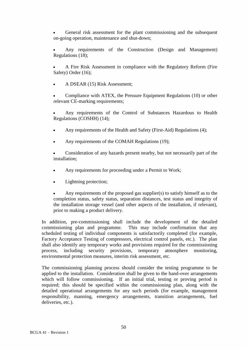
50 BCGA 41 – Revision 1
General risk assessment for the plant commissioning and the subsequent
on-going operation, maintenance and shut-down;
Any requirements of the Construction (Design and Management)
Regulations (18);
A Fire Risk Assessment in compliance with the Regulatory Reform (Fire
Safety) Order (16);
A DSEAR (15) Risk Assessment;
Compliance with ATEX, the Pressure Equipment Regulations (10) or other
relevant CE-marking requirements;
Any requirements of the Control of Substances Hazardous to Health
Regulations (COSHH) (14);
Any requirements of the Health and Safety (First-Aid) Regulations (4);
Any requirements of the COMAH Regulations (19);
Consideration of any hazards present nearby, but not necessarily part of the
installation;
Any requirements for proceeding under a Permit to Work;
Lightning protection;
Any requirements of the proposed gas supplier(s) to satisfy himself as to the
completion status, safety status, separation distances, test status and integrity of
the installation storage vessel (and other aspects of the installation, if relevant),
prior to making a product delivery.
In addition, pre-commissioning shall include the development of the detailed
commissioning plan and programme. This may include confirmation that any
scheduled testing of individual components is satisfactorily completed (for example,
Factory Acceptance Testing of compressors, electrical control panels, etc.). The plan
shall also identify any temporary works and provisions required for the commissioning
process, including security provisions, temporary atmosphere monitoring,
environmental protection measures, interim risk assessment, etc.
The commissioning planning process should consider the testing programme to be
applied to the installation. Consideration shall be given to the hand-over arrangements
which will follow commissioning. If an initial trial, testing or proving period is
required; this should be specified within the commissioning plan, along with the
detailed operational arrangements for any such periods (for example, management
responsibility, manning, emergency arrangements, transition arrangements, fuel
deliveries, etc.).

51 BCGA 41 – Revision 1
Consideration shall be given to the on-going operation of the plant, following
commissioning. A detailed plan shall be developed for the commissioning process, to
ensure a comprehensive regime exists for a smooth and safe process of setting the
equipment to work. This may include contingency plans for foreseeable yet unplanned
events. The competence, skills and abilities of the site operator, their employees, as
well as maintenance staff shall be assessed by the operator prior to commissioning to
ensure that the installation can be managed appropriately in the post-commissioning
phase. Competence development, instruction and familiarisation may be required to
ensure that site personnel are adequately briefed. It may be beneficial to plan for the
site personnel to witness aspects of the commissioning process and / or work alongside
the commissioning team, in order to better equip them (site personnel) with the
competence to safely operate the installation. As appropriate, such joint-working
competence-development opportunities should be offered by the commissioning team.
Where specialist maintainers are engaged (for example, for the maintenance of large or
innovative plant items such as compressors), then training and familiarisation plans
shall be developed accordingly.
Instrument calibration, machinery adjustment and system purging will typically be
required before a system can be considered as suitable for commissioning.
Proof pressure testing (if required) and leak testing of the pressure vessels, process
equipment, pipework and connections shall be carried out as appropriate. This may
require a proof pressure or other test(s) to be witnessed, for example, by a Notified
Body representative, where the installation is required to be CE marked.
Guidance on the requirements of pressure testing, and the hazards that should be
considered, can be found in HSE GN GS4 (66), Safety in pressure testing, and BS EN
13445-5 (41), Unfired pressure vessels – Part 5 - Inspection and testing.
NOTE: It is recommended that hydrogen systems are leak tested using helium, or
an appropriate inert gas mixture containing helium, due to the propensity of hydrogen
to leak through holes that would otherwise appear leak-tight if tested with gases with
larger molecular sizes such as nitrogen. It is recommended that CNG and LNG systems
are tested using an inert gas, such as nitrogen, to purge piping systems of atmospheric
air, moisture and flammable concentrations of gaseous fuels during commissioning,
maintenance and periodic inspection. It is recommended on commissioning and
decommissioning of LNG storage vessels that liquid nitrogen is used for purging and
cool down of the inner vessel. Purging and leak testing shall be subject to a
documented risk assessment that takes into account the hazards of using inert gases
(such as the potential to asphyxiate). Refer to IGEM UP/20 (90), ISO 16923 (52),
IGEM UP/21 (91) and ISO 16924 (53).
Acceptance testing of the operation of the plant using an inert gas should be considered
where possible prior to the introduction of flammable gases.
Key safety and process integrity provisions such as interlocks and control circuitry
should be verified prior to the introduction of product, especially where the product is
flammable. Temporary provisions may be required for the securing of special tools,
keys, lock-offs, fuses, couplings, etc. at various stages of the commissioning process.
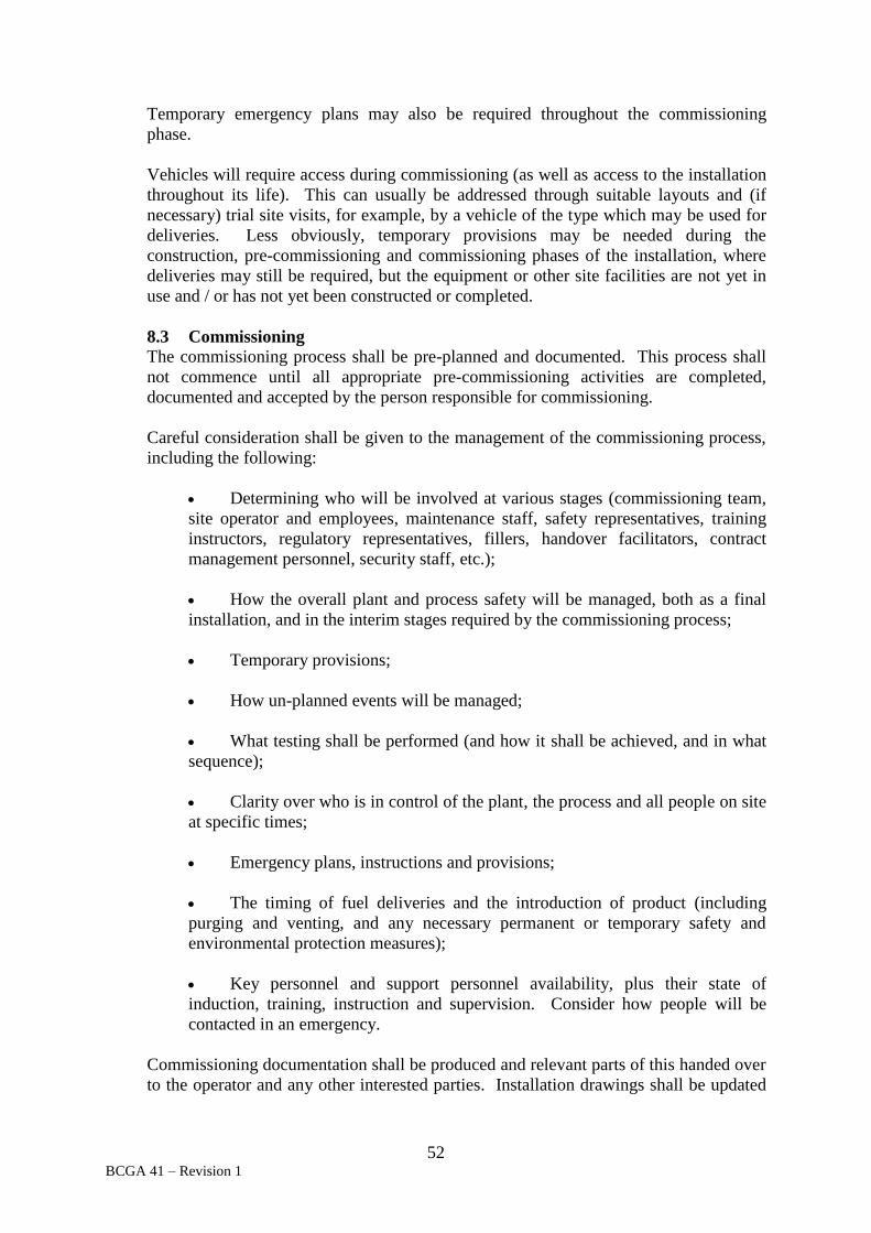
52 BCGA 41 – Revision 1
Temporary emergency plans may also be required throughout the commissioning
phase.
Vehicles will require access during commissioning (as well as access to the installation
throughout its life). This can usually be addressed through suitable layouts and (if
necessary) trial site visits, for example, by a vehicle of the type which may be used for
deliveries. Less obviously, temporary provisions may be needed during the
construction, pre-commissioning and commissioning phases of the installation, where
deliveries may still be required, but the equipment or other site facilities are not yet in
use and / or has not yet been constructed or completed.
8.3 Commissioning
The commissioning process shall be pre-planned and documented. This process shall
not commence until all appropriate pre-commissioning activities are completed,
documented and accepted by the person responsible for commissioning.
Careful consideration shall be given to the management of the commissioning process,
including the following:
Determining who will be involved at various stages (commissioning team,
site operator and employees, maintenance staff, safety representatives, training
instructors, regulatory representatives, fillers, handover facilitators, contract
management personnel, security staff, etc.);
How the overall plant and process safety will be managed, both as a final
installation, and in the interim stages required by the commissioning process;
Temporary provisions;
How un-planned events will be managed;
What testing shall be performed (and how it shall be achieved, and in what
sequence);
Clarity over who is in control of the plant, the process and all people on site
at specific times;
Emergency plans, instructions and provisions;
The timing of fuel deliveries and the introduction of product (including
purging and venting, and any necessary permanent or temporary safety and
environmental protection measures);
Key personnel and support personnel availability, plus their state of
induction, training, instruction and supervision. Consider how people will be
contacted in an emergency.
Commissioning documentation shall be produced and relevant parts of this handed over
to the operator and any other interested parties. Installation drawings shall be updated

53 BCGA 41 – Revision 1
during commissioning to ensure that a final set of accurate 'as constructed' drawings are
developed.
Testing results shall be documented and retained.
Legislative requirements shall be adhered to during commissioning, in accordance with
the commissioning plan. Some legislative requirements may come into force before
certain aspects of commissioning commence (for example, the requirement for a
Written Scheme of Examination under PSSR (12), prior to pressurising the system),
whilst others may not apply until the end of the commissioning phase, or at some
intermediate point. Commissioning therefore needs to be carefully planned by
knowledgeable and competent persons.
An Ageing Pressure Equipment Assessment in accordance with BCGA CP 39 (84),
shall be completed immediately prior to or at the initial setting to work of the pressure
system(s).
8.4 Handover for operation
Handover will generally follow successful commissioning. Typically the equipment
supplier / installer will transfer ownership and responsibility to the owner / user,
however this will depend on the contractual agreements in place.
It is unlikely that handover will be effected before all supplier / installer regulatory and
legislative preliminaries are completed. Exceptions to this may be where the owner /
user wish to retain responsibility for some aspects themselves (for example, licensing,
PSSR (12) Schedule 2 responsibilities, operational personnel training and management,
etc.).
A joint final inspection, familiarisation and orientation visit shall be offered at handover
stage, with representatives from all interested parties. The inspection may be taken as
an opportunity to confirm the completion status of the installation, and the suitability of
the installation for handover. A structured checklist is recommended to ensure that all
relevant items are complete. This may include legislative aspects; satisfactory access
safety provisions are in place, labelling (including clear demarcation to DSEAR (15)
requirements), signage, housekeeping, security etc. Further guidance on the
verification checks that should be carried out by the owner / user before the workplace
is first used can be found in HSE L138 (71). While there is no requirement to keep a
record of the handover, it is recommended that the name of the person carrying out the
handover is recorded, and the date on which it was completed as a minimum
requirement.
The supplier/ installer shall provide to the operator:
A set of technical information which includes:
o An operating manual covering safe operation and care of the
installation, including emergency shut-down procedures.
o Drawings, diagrams and plans for example, electrical schematics,
piping diagrams, P&ID, etc. These shall include a set of working drawings,

54 BCGA 41 – Revision 1
of sufficient accuracy to enable the plant to be operated and maintained
safely.
o Information to allow a DSEAR (15) Risk Assessment to be
undertaken, if this has not previously been completed. Drawings
identifying the hazardous areas and types of zones shall be provided, with
supplementary text providing information about the dangerous substances
present, the activities that have been assessed and any assumptions that
have been made. These documents should be available on-site at all times,
and should be considered whenever new equipment is to be introduced into
a zoned area. Guidance on hazardous area drawings is available from EN
60079-10-1 (60) and EI 15 (93).
o Test certificates.
o Any CE Marking documentation.
o Any requirements stemming from the Construction (Design and
Management) Regulations (18), including information to be transferred to
the Client such as significant residual risks.
A demonstration of the correct operation of the equipment.
Training, instruction and information for user personnel in accordance with
Section 9.
The provision of a contact address and emergency telephone number for
relevant post-handover support.
The Operator shall ensure:
He has all the necessary information to enable him to carry out his duties in
law, for example, PSSR (12), the Pressure Equipment Regulations (10), DSEAR
(15) etc.
He has all the necessary information to enable him to carry out the required
Risk Assessments and develop and implement the necessary safe system(s) of
work.
All necessary personnel are competent to fulfil their and their employer’s
relevant duties. The provision of information, instruction and training should be
recorded.
All the equipment can be operated safely.
Appropriate fire management and control equipment is in place.
Appropriate security arrangements are provided.

55 BCGA 41 – Revision 1
8.5 End of Life
At the end of filling station life, decommissioning strategies shall be adopted in
accordance with the Blue Book (94) and in accordance with gas company procedures.
Special consideration shall be given to emptying, purging and decommissioning low
temperature / cryogenic vessels.
9. OPERATION
When putting storage tanks into service for first filling, and then for the subsequent system
operation, in-service and maintenance requirements, the Gas Supplier and the Operator (as
appropriate) shall comply with BCGA CP 46 (86) and the following requirements:
9.1 Delivery
The delivery or bulk-filling requirements for any specific installation shall be
considered as part of the installation design, and shall be confirmed following a
documented site-specific delivery risk assessment. This site-specific risk assessment
shall take account of all aspects of the ‘as constructed’ installation, and of relevant
foreseeable hazards.
Various factors affect the site-specific delivery risk assessment. These include:
The ease with which a delivery vehicle (or a range of relevant vehicles) can
access the installation;
Delivery management (drive-away prevention, security, impact or collision
prevention, work at height, inventory management and minimisation, etc.);
The presence on site of various fuels, goods, substances and activities;
The presence on site of hazardous materials and substances;
The presence or possible presence on site of sources of ignition;
The management of potential multiple deliveries and / or simultaneous fuel
deliveries (for example, simultaneous arrival of different fuel types);
Any areas zoned under DSEAR (15);
The control of persons (public, delivery agents, own personnel) in and
around the delivery area(s);
Control of the behaviour of persons, for example, smoking, mobile phone
usage;
The advisability or otherwise of continuing to allow the dispensing of fuel
to / by customers during fills and deliveries (or indeed to allow the presence of
particular groups of persons in specific circumstances);
The availability and competence of personnel;
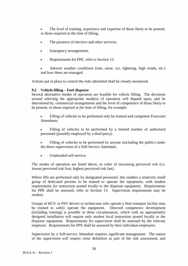
56 BCGA 41 – Revision 1
The level of training, experience and expertise of those likely to be present,
or those required at the time of filling;
The presence of electrics and other services;
Emergency arrangements.
Requirements for PPE, refer to Section 13.
Adverse weather conditions (rain, snow, ice, lightning, high winds, etc.)
and how these are managed.
Actions put in place to control the risks identified shall be closely monitored.
9.2 Vehicle filling – Fuel dispense
Several alternative modes of operation are feasible for vehicle filling. The decisions
around selecting the appropriate mode(s) of operation will depend upon, and be
determined by, commercial arrangements and the level of competence of those likely to
be present, or those required at the time of filling, for example:
Filling of vehicles to be performed only by trained and competent Forecourt
Attendants;
Filling of vehicles to be performed by a limited number of authorised
personnel (possibly employed by a third party);
Filling of vehicles to be performed by anyone (including the public) under
the direct supervision of a Self-Service Attendant;
Unattended self-service.
The modes of operation are listed above, in order of increasing perceived risk (i.e.
lowest perceived risk first, highest perceived risk last).
Where fills are performed only by designated personnel, this enables a relatively small
group of dedicated persons to be trained to operate the equipment, with modest
requirements for instruction posted locally to the dispense equipment. Requirements
for PPE shall be assessed, refer to Section 13. Supervision requirements may be
modest.
Groups of HGV or PSV drivers or technicians who operate a fleet transport facility may
be trained to safely operate the equipment. Directed competence development
(including training) is possible in these circumstances, which with an appropriately
designed installation will require only modest local instruction posted locally to the
dispense equipment. Requirements for supervision shall be assessed by the relevant
employer. Requirements for PPE shall be assessed by their individual employers.
Supervision by a Self-service Attendant requires significant management. The nature
of the supervision will require close definition as part of the risk assessment, and

57 BCGA 41 – Revision 1
controls will be needed to ensure that supervision is maintained to the required degree.
Security 'hard controls' may be needed to guarantee the required level of effectiveness,
for example, by individually authorising fuel transfer once the couplings are confirmed
as correctly attached. This may be achieved through the use of a security key, PC
password, etc. Local point-of-use instruction and information shall be provided to
ensure safety arrangements are complied with.
Unattended self-service should be considered as a viable option only where it can be
effectively and safely managed. Local point-of-use instruction shall be provided to
ensure that adequate guidance is provided to dispense equipment operators. Even
where fills are unsupervised, it is envisaged that surveillance should be provided (for
example by Closed- Circuit Television (CCTV) or by an alarm call-out system) to
enable emergency situations to be managed. Similarly, staff should visit the forecourt
and installation regularly, to ensure that all relevant aspects are in order, such as
housekeeping, equipment condition, emergency arrangements, signage, etc.
NOTE: CCTV surveillance cameras can capture and record personal and vehicle
details. The data obtained by using surveillance cameras is subject to The Data
Protection Act (3) and as such their use, and the recorded data, requires appropriate
management controls. The Data Protection Act (3) regulates how personal information
is used by organisations, businesses or the government. Everyone responsible for using
data has to follow strict rules called ‘data protection principles’. The Information
Commissioner’s Office publishes a Code of Practice for surveillance cameras, In the
picture: A data protection code of practice for surveillance cameras and personal
information (109).
The mode of operation shall be determined as part of the concept design phase of an
installation, the earlier the better. Once an installation is in physical existence, any
changes to the mode of operation shall be subject to a documented risk assessment and
change-management process. Such changes may not be straightforward.
10. PERIODIC EXAMINATION AND MAINTENANCE
A planned maintenance schedule shall be prepared for each installation. BCGA CP 39 (84)
provides information on the in-service requirements of pressure equipment. Pressure vessels,
and other in-scope parts of pressure systems shall periodically be examined in accordance
with a Written Scheme of Examination, as required by the PSSR (12).
Housekeeping checks shall be carried out on a regular basis. At attended stations it is
recommended that checks are carried out at each operator shift-change and, as a minimum,
daily. Ideally, and where daily opening hours are observed, such checks shall be performed
prior to the installation opening for customers. Daily housekeeping checks shall include:
The control of rubbish and detritus;
The management of (i.e. ensuring the absence of) flammable and combustible
material, or any other object(s) affecting the ATEX (23) / DSEAR (15) hazardous area
risk assessment;
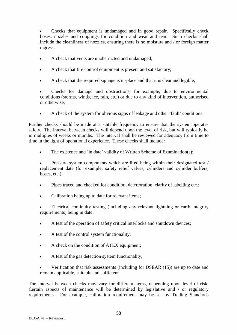
58 BCGA 41 – Revision 1
Checks that equipment is undamaged and in good repair. Specifically check
hoses, nozzles and couplings for condition and wear and tear. Such checks shall
include the cleanliness of nozzles, ensuring there is no moisture and / or foreign matter
ingress;
A check that vents are unobstructed and undamaged;
A check that fire control equipment is present and satisfactory;
A check that the required signage is in-place and that it is clear and legible;
Checks for damage and obstructions, for example, due to environmental
conditions (storms, winds, ice, rain, etc.) or due to any kind of intervention, authorised
or otherwise;
A check of the system for obvious signs of leakage and other ‘fault’ conditions.
Further checks should be made at a suitable frequency to ensure that the system operates
safely. The interval between checks will depend upon the level of risk, but will typically be
in multiples of weeks or months. The interval shall be reviewed for adequacy from time to
time in the light of operational experience. These checks shall include:
The existence and ‘in date’ validity of Written Scheme of Examination(s);
Pressure system components which are lifed being within their designated test /
replacement date (for example; safety relief valves, cylinders and cylinder buffers,
hoses, etc.);
Pipes traced and checked for condition, deterioration, clarity of labelling etc.;
Calibration being up to date for relevant items;
Electrical continuity testing (including any relevant lightning or earth integrity
requirements) being in date;
A test of the operation of safety critical interlocks and shutdown devices;
A test of the control system functionality;
A check on the condition of ATEX equipment;
A test of the gas detection system functionality;
Verification that risk assessments (including for DSEAR (15)) are up to date and
remain applicable, suitable and sufficient.
The interval between checks may vary for different items, depending upon level of risk.
Certain aspects of maintenance will be determined by legislative and / or regulatory
requirements. For example, calibration requirement may be set by Trading Standards

59 BCGA 41 – Revision 1
guidelines, electrical earthing by international technical standards, fire control system checks
by Fire Safety legislation, etc.
The maintenance of specific items of plant shall generally and initially be set in accordance
with the manufacturer's instructions and recommendations (in the absence of operating
experience).
It is recommended that a definitive inspection and maintenance plan should be created and
implemented for each fuel station.
To minimise hazards caused by modifications, formal and documented Management of
Change processes shall be followed. Any changes to the plant should be subjected to
technical assessment to ensure no potential hazards are introduced by their inclusion into (or
exclusion from) the overall system, installation or environment. Any changes shall be pre-
authorised by competent personnel, including where maintenance activity involves a desire to
replace plant / equipment with items that are not like-for-like. Documentation, drawings,
technical files, maintenance schedules, etc. shall be updated consistently with any alterations.
EIGA Document 51 (77), Management of change, provides guidance on management of
change.
If invasive maintenance is necessary, purging and isolation procedures shall be adopted to
ensure a flammable atmosphere is not created. On completion of invasive maintenance, a
leak test using an inert fluid, and subsequent purging should be carried out to prevent
formation of a flammable atmosphere prior to the re-commissioning.
NOTE: It is recommended that hydrogen systems are leak tested using helium, or an inert
gas mixture containing helium, due to the propensity of hydrogen to leak from assemblies
and components that would otherwise appear leak-tight if tested with gases with larger
molecular sizes such as nitrogen. It is recommended that CNG and LNG installations are
leak tested using nitrogen.
The interval between (one or more) Written Schemes of Examination shall be set by the
User’s designated Competent Person for PSSR (12). The examination intervals are likely to
be measured in months and years, rather than in weeks.
An Ageing Pressure Equipment Assessment in accordance with BCGA CP 39 (84) shall be
completed along with each Written Scheme(s) of Examination and at initial installation. The
results of the assessment may require that changes be made to subsequent intervals between
examination, inspection or replacement activities, for any item, or may generate other
corrective action.
Where maintenance activities are carried out that have been identified as higher risk and
requiring the adoption of a controlled method in order to manage the risks, these activities
shall be performed under a permit-to-work system, to ensure:
Adequacy of communication between relevant parties involved, for example, the
site manager, the owner, the user, the operator, the gas supplier and equipment supplier,
the installer, those who carry out the work, etc.;

60 BCGA 41 – Revision 1
Clear identification of who may authorise particular jobs and who is responsible
for specifying and implementing the necessary precautions and controls;
Clear identification of the types or sections of work considered hazardous;
Clear and standardised identification of tasks, risk assessments, permitted task
duration and supplemental or simultaneous activity and control measures.
Clarity of scope.
For guidance on permit to work systems refer to HSG 250 (65), Guidance on permit-to-work
systems and EIGA Document 40 (76), Work permit systems.
11. FUEL QUALITY
Various fuels, grades and purities are available for installations within the scope of this code.
Where different fuel quality grades and types are available at the same filling installation,
physical differences between the connectors and nozzles used may not be obvious. Labelling
of the grade and type of fuel available at a specific dispenser / nozzle should be clear to
ensure operator and / or customers are fully aware of what product is available for dispense.
Refer to Figure 5.
Where required, quality samples should be taken from the dispensing nozzle. Precautions
shall be taken to prevent over-pressurisation of the sample vessel being used and to prevent
contamination (for example, by purge gas or atmospheric air). This approach may require the
sample container and sampling assembly to have a rated service pressure at least equal to the
maximum allowable working pressure of the dispensing system from which the sample is
taken, or utilise suitably sized and rated Pressure Relief Devices (PRDs) or other suitable
counter-measures. Risk assessment specific to the sampling activity shall be prepared and
measures taken to minimise the likelihood of unintentional releases, or potential hazardous
releases whilst undertaking the sampling. Leak testing of the sampling equipment with an
inert fluid is recommended prior to taking a flammable gas sample.
Consideration should be given to maintaining the quality of the fuel at the nozzle, between
the dispenser and the customer vehicle. Directions to the filling operative should include
inspection of the nozzle and vehicle receptacle for obvious contamination prior to connection
to the vehicle, in addition to any potential safety issues from damage or wear to the nozzle or
receptacle.
Management controls are to ensure the fuel quality is not affected by invasive maintenance or
by contaminants introduced by fuel deliveries. Fuel delivery staff are to receive appropriate
training and supervision to provide the necessary quality assurance.
Specific fuel quality issues are noted as follows:
11.1 Proton Exchange Membrane hydrogen
Proton Exchange Membrane (PEM) hydrogen fuel cell engine road vehicles (FCV)
have low tolerance to hydrogen fuel contaminants. ISO 14687-2 (46), Hydrogen fuel.

61 BCGA 41 – Revision 1
Product specification. Proton Exchange Membrane (PEM) fuel cell applications for
road vehicles, specifies the quality characteristics of two grades of hydrogen fuel ‘Type
I, Grade D’ and ‘Type II, Grade D’ (for gaseous and liquid hydrogen respectively),
intended to apply to the interim stage of use of PEM FCV on a limited production scale.
The permitted contaminant levels are mirrored in the standard SAE J2719 (98),
Hydrogen fuel quality for fuel cell vehicles. ISO 14687-2 (46) also includes guidance
for standardised analytical techniques.
NOTE: At the time of preparing this code of practice, the requirements for the
analysis of hydrogen supplied to vehicles were under development, with no ability in
the UK to fully analyse hydrogen samples taken from the dispensing nozzle to the
requirements of ISO 14687-2 (46).
11.2 Non-Proton Exchange Membrane hydrogen Vehicles equipped with hydrogen internal combustion engines (ICE) are substantially
less sensitive to fuel purity than are vehicles with PEM hydrogen engines.
Consequently fuel quality requirements for hydrogen ICE engines and vehicles are
significantly less onerous than for PEM hydrogen. Where hydrogen dispensers are
used for both FCV and ICE vehicles, the quality requirements of the FCVs shall dictate
the quality of hydrogen dispensed. Quality specifications for non-PEM hydrogen are
available from gas suppliers.
11.3 CNG and LNG
The specification data for LNG and CNG may alternatively be described by gas
suppliers as ‘Natural Gas, refrigerated, liquid’ for LNG, and ‘Methane, compressed’ or
‘Natural gas, compressed’ for CNG.
CNG is stored under high pressure at ambient temperature and quality does not
deteriorate over time.
Quality specifications for CNG and LNG are available from gas suppliers. The supply
of CNG and LNG shall meet minimum methane numbers as recommended by the
engine manufacturer to maintain fuel quality, engine performance and combustion pre-
detonation.
For CNG refer to ISO 15403-1 (47), Natural gas -- Natural gas for use as a
compressed fuel for vehicles - Part 1: Designation of the quality.
NOTE: European standards for natural gas fuel quality have recently been issued or
are being developed:
EN 16726 (51), Gas infrastructure - Quality of gas - Group H;
prEN 16723-1 (50), Natural gas and biomethane for use in transport and
biomethane for injection in the natural gas network - Part 1: Specifications for
biomethane for injection in the natural gas network.
prEN 16723-2 (50), Natural gas and biomethane for use in transport and
biomethane for injection in the natural gas network - Part 2: Automotive fuel
specifications;
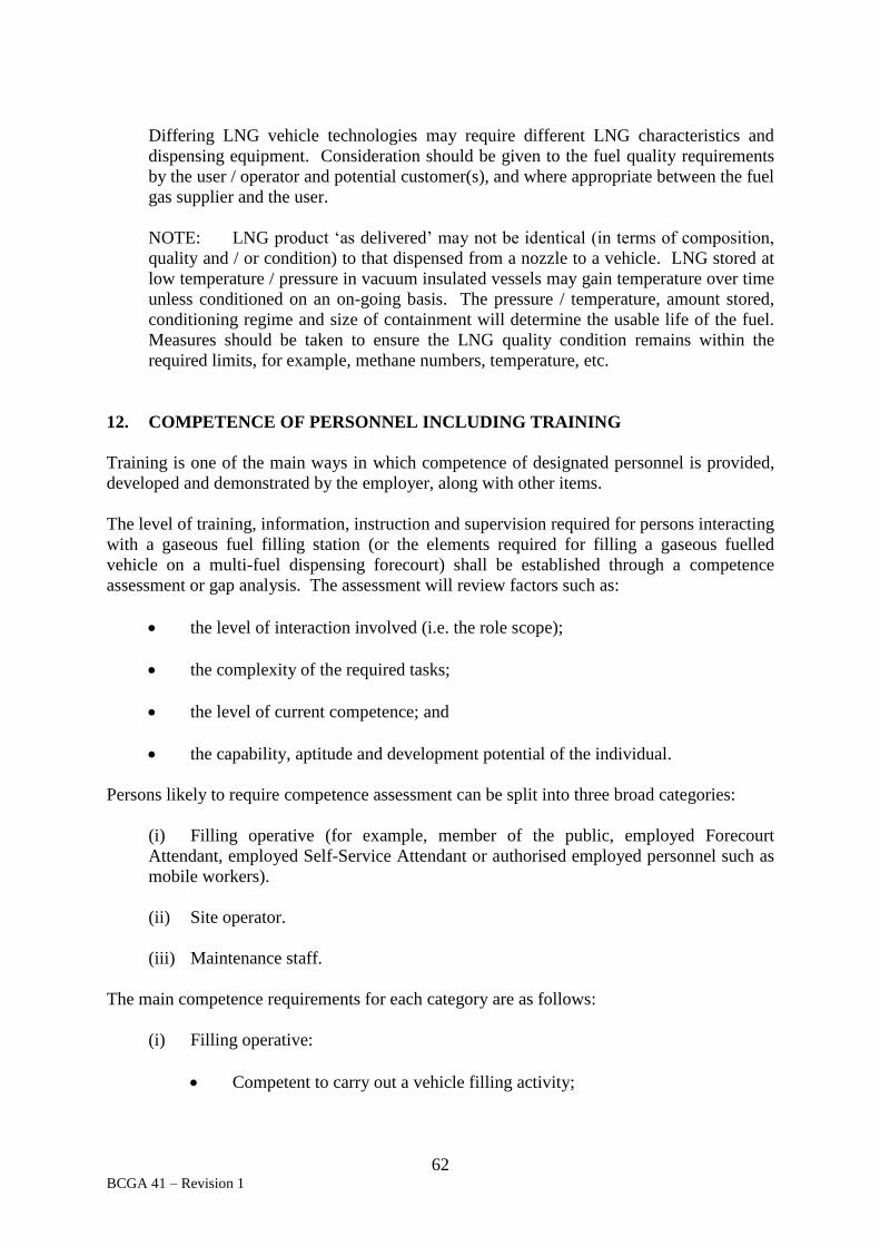
62 BCGA 41 – Revision 1
Differing LNG vehicle technologies may require different LNG characteristics and
dispensing equipment. Consideration should be given to the fuel quality requirements
by the user / operator and potential customer(s), and where appropriate between the fuel
gas supplier and the user.
NOTE: LNG product ‘as delivered’ may not be identical (in terms of composition,
quality and / or condition) to that dispensed from a nozzle to a vehicle. LNG stored at
low temperature / pressure in vacuum insulated vessels may gain temperature over time
unless conditioned on an on-going basis. The pressure / temperature, amount stored,
conditioning regime and size of containment will determine the usable life of the fuel.
Measures should be taken to ensure the LNG quality condition remains within the
required limits, for example, methane numbers, temperature, etc.
12. COMPETENCE OF PERSONNEL INCLUDING TRAINING
Training is one of the main ways in which competence of designated personnel is provided,
developed and demonstrated by the employer, along with other items.
The level of training, information, instruction and supervision required for persons interacting
with a gaseous fuel filling station (or the elements required for filling a gaseous fuelled
vehicle on a multi-fuel dispensing forecourt) shall be established through a competence
assessment or gap analysis. The assessment will review factors such as:
the level of interaction involved (i.e. the role scope);
the complexity of the required tasks;
the level of current competence; and
the capability, aptitude and development potential of the individual.
Persons likely to require competence assessment can be split into three broad categories:
(i) Filling operative (for example, member of the public, employed Forecourt
Attendant, employed Self-Service Attendant or authorised employed personnel such as
mobile workers).
(ii) Site operator.
(iii) Maintenance staff.
The main competence requirements for each category are as follows:
(i) Filling operative:
Competent to carry out a vehicle filling activity;

63 BCGA 41 – Revision 1
Able to identify issues before and during dispensing and able to abort the
dispensing activity;
Able to identify vehicles ‘in scope’ and ‘out of scope’ of his competence
and /or the capability of the installation;
If employed, able to safely work with periodic audit ‘spot check’-style
supervision and periodic, on-the-job coaching and periodic competence re-
assessment (with competence refresher activity as required);
Where appropriate (for example, for members of the public and mobile
workers) the required competence may be established simply by the provision of
adequate instructions on the dispenser, and in the instruction manual of the
vehicle being filled;
Special consideration shall be given to low temperature / cryogenic gas
handling competencies.
The competence of the operative (including members of the public) should
be supplemented by the supervisory overview of the site operator or through
active remote monitoring.
(ii) Site operator:
Shall have an understanding of all fuels on-site, and basic safety aspects for
deliveries and dispense of each fuel in order to supervise the safe filling of
vehicles by other competent personnel and/or the public. The site operator shall
also understand the particular filling procedures for different vehicle model types
such as filling pressure requirements and specific gas quality criteria;
Shall be familiar with the operational requirements of the dispensing and
associated equipment, and able to identify issues, abnormal operation, etc.;
Shall be able to recognise the need for, and quickly make safe (for example,
through shut down of) the plant either locally or remotely;
Shall be able to draw up, and shall maintain and implement an emergency
response plan;
Contact and liaise with emergency services, gas supplier and equipment
supplier / installer, including during routine bulk deliveries;
Have sufficient knowledge of the fuel storage and dispensing equipment to
manage routine start-up, maintenance management, shut-down and other aspects
appropriate to the system(s). This may include changing cylinders, and purging
manifolds where appropriate.
(iii) Maintenance staff:

64 BCGA 41 – Revision 1
Maintenance staff who are typically employed by the equipment supplier, installer,
operator or the gas supplier.
Will have significant knowledge and understanding of the design, maintenance and
operational elements of both the gas dispensing and storage / generation equipment, as
appropriate (or having ready access to such knowledge, on demand). The maintenance
staff may not necessarily have an understanding of requirements for other fuel storage
and dispensing equipment on the premises (for example, liquid petroleum, fuel-oils,
etc.), but will require an understanding of how the gaseous fuel system impacts on
these, and vice-versa, in respect of maintenance.
Where specific equipment maintenance is sub-contracted, the sub-contractor may not
require an understanding of the complete system as long as the operational /
maintenance staff remain responsible for controlling any maintenance work, including
retaining responsibility for the decommissioning and / or preparation of the system,
sequencing of activities, issuing permits to work, overall supervision, etc. and safely
returning the system into operation.
The delivery driver from the gas supplier may not necessarily have a full understanding of the
entire gaseous system, however the delivery driver shall have a thorough understanding of the
delivery process and related equipment.
All persons interacting with the station shall wear the appropriate personal protective
equipment (PPE), refer to Section 13, and shall comply with gas company and local site rules.
A non-exhaustive summary of the competence requirements that may be relevant to the
different persons interacting with the station is provided in Table 4. Commissioning and
maintenance engineers, or specifically trained industrial gas company staff should be
expected to demonstrate further competence, and receive additional competence development
beyond that summarised in Table 6, such as the generic training included in BCGA GN 23
(88), Identifying gas safety training requirements in the workplace.
Additional competence development may be appropriate for maintaining the quality of the
fuel gas.
Specific training shall be provided to designated first aiders who may be called upon in the
event of an incident, for example, cold burn injuries as a result of exposure to low
temperature / cryogenic substances. HSE L74 (68), First aid at work. The Health and Safety
(First-Aid) Regulations 1981, provides guidance for employers on providing first aid in the
workplace.
It is recommended that the Fire and Rescue Service and other first responders who may be
called in the case of an alarm or incident should be invited to familiarise themselves with the
equipment, processes, and potential hazards associated with the storage or dispensing of
gaseous fuels. There is a benefit in also providing information on the types of vehicles using
the filling station.
Competence assurance checks and regular refresher sessions should be provided as
appropriate.
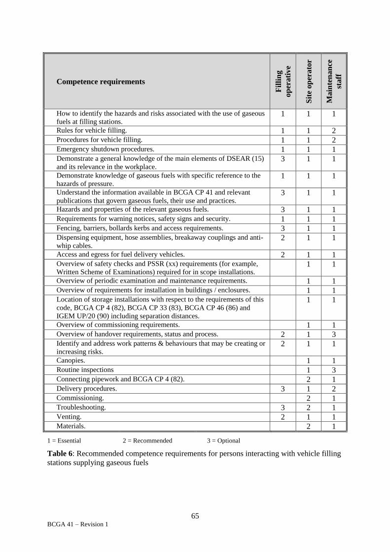
65 BCGA 41 – Revision 1
Competence requirements
Fil
lin
g
op
erati
ve
Sit
e op
erato
r
Main
ten
an
ce
staff
How to identify the hazards and risks associated with the use of gaseous
fuels at filling stations. 1 1 1
Rules for vehicle filling. 1 1 2 Procedures for vehicle filling. 1 1 2 Emergency shutdown procedures. 1 1 1 Demonstrate a general knowledge of the main elements of DSEAR (15)
and its relevance in the workplace. 3 1 1
Demonstrate knowledge of gaseous fuels with specific reference to the
hazards of pressure. 1 1 1
Understand the information available in BCGA CP 41 and relevant
publications that govern gaseous fuels, their use and practices. 3 1 1
Hazards and properties of the relevant gaseous fuels. 3 1 1 Requirements for warning notices, safety signs and security. 1 1 1 Fencing, barriers, bollards kerbs and access requirements. 3 1 1 Dispensing equipment, hose assemblies, breakaway couplings and anti-
whip cables. 2 1 1
Access and egress for fuel delivery vehicles. 2 1 1 Overview of safety checks and PSSR (xx) requirements (for example,
Written Scheme of Examinations) required for in scope installations. 1 1
Overview of periodic examination and maintenance requirements. 1 1 Overview of requirements for installation in buildings / enclosures. 1 1 Location of storage installations with respect to the requirements of this
code, BCGA CP 4 (82), BCGA CP 33 (83), BCGA CP 46 (86) and
IGEM UP/20 (90) including separation distances.
1 1
Overview of commissioning requirements. 1 1 Overview of handover requirements, status and process. 2 1 3 Identify and address work patterns & behaviours that may be creating or
increasing risks. 2 1 1
Canopies. 1 1 Routine inspections 1 3 Connecting pipework and BCGA CP 4 (82). 2 1 Delivery procedures. 3 1 2 Commissioning. 2 1 Troubleshooting. 3 2 1 Venting. 2 1 1 Materials. 2 1
1 = Essential
2 = Recommended
3 = Optional
Table 6: Recommended competence requirements for persons interacting with vehicle filling
stations supplying gaseous fuels

66 BCGA 41 – Revision 1
13. PERSONAL PROTECTIVE EQUIPMENT
The work activity risk assessment will determine the requirement for the use of hazard
controls, including PPE. PPE may only be considered as a control to achieve an acceptable
level of residual risk after other levels of control have been addressed. Where PPE is
required a PPE Assessment is to be carried out. PPE is to be provided as required by the
Personal Protective Equipment Regulations (13). The PPE shall be selected for a particular
task and location and shall be appropriate and chosen to effectively reduce the overall risk.
Thus there are different PPE requirements for differing products, different tasks and possibly
different personnel. Due regard is to be given to the requirements of the COSHH Regulations
(14), any relevant equipment publications, manufacturers information and the product Safety
Data Sheet.
HSE L25 (67), Personal Protective Equipment at Work, provides guidance on the Personal
Protective Equipment Regulations (13). EIGA Document 136 (80), Selection of personal
protective equipment, provides guidance for selecting and using PPE at work.
All the safety aspects of handling cryogenic liquid cannot be covered adequately in this Code
of Practice. For further information refer to the British Cryoengineering Society, Cryogenic
Safety Manual (110).
13.1 Public access filling
The wearing of PPE by the general public can not be guaranteed. For public filling
tasks, the filling station shall not rely on PPE to reduce the level of residual risk. This
consideration should, however, not be used as a justification to not provide optional
PPE for use by those members of the public who wish to use PPE.
The advisability of filling cryogenic fuels by untrained persons such as the general
public (unless all risks can be managed without recourse to PPE) should be carefully
considered. Where PPE is required to control risks, this is likely to be sufficiently
problematic to render it inappropriate for members of the general public to fill
cryogenically-fuelled vehicles.
13.2 Non-public access filling Where filling stations are to be used by specialist (competent and employed) personnel
only, for example, captive fleets, the safety requirements of the filling operation should
be determined by risk assessment. PPE should be appropriate to the level of residual
risk of any hazards. These risks are typically pressure, temperature, asphyxiation, risk
of ignition (including static electricity accumulation), fire and vehicle movements.
13.3 Maintenance and fuel delivery
Specialist personnel involved in maintenance and fuel delivery activities shall wear
PPE as required by their employers’ policies and instructions.
14. EMERGENCY SITUATIONS AND PROCEDURES
Emergency procedures shall be documented for each site. The procedures may take a variety
of forms (and may include codified documents, signage and notices, operating instructions,
procedures manual, etc.).

67 BCGA 41 – Revision 1
Typically, the emergency procedures should encompass the following:
Any statutory requirements, including any requirements stemming from local
authority planning considerations or COMAH (19) in-scope sites;
Liquid fuel spills;
Gas leak (storage);
Gas leak (forecourt);
Incident occurring nearby that could affect dispensing and / or storage
installations;
Incident occurring on site;
Arrangements to contact emergency services, equipment supplier, installer, gas
supplier, maintainers and other specialists;
Security procedures, including, as appropriate, evacuation and invacuation;
Arrangements with and for nearby residents, sensitive receptors, land owners or
other interested parties;
Positioning, duplication and operation of emergency switches, controls, fire
management and first aid equipment.
Consideration should be given to the provision of additional equipment to manage
foreseeable emergency situation, for example, spill kits, fire control equipment etc.
The site operator and employees shall be competent to apply the full suite of emergency
procedures. Competence shall be assured through information, supervision, coaching,
rehearsed events, training and refresher training, to ensure the level of knowledge and
competence of staff is maintained at a high level.
New personnel shall be appropriately inducted to ensure they are suitably competent to safely
fulfil their role. An increased level of supervision may be required for new inductees, until
their competence across the full range of activities is developed and proven. Similar
provisions shall apply, on a risk-assessed basis, for any temporary, visiting or short-term
personnel.
Procedures shall be subject to regular review, for example following an incident or a
significant change or if not reviewed for these reasons then at a specific interval, along with
any risk assessments that are linked to the emergency procedures (for example, First Aid,
DSEAR (15), etc.).
Rehearsal of any specific procedure shall be performed from time to time, as appropriate, to
check the adequacy of the procedure, the competence and preparedness of personnel,
management system, validate the expected outcome, learn and develop etc.
68 BCGA 41 – Revision 1
Procedures should be clearly marked with authorised names and signatures, date(s) of issue
(including any re-issues, reviews or revisions), contact names for updates and feedback, etc.
These procedures may (in addition) be advertised locally (for example, on a notice board, on
relevant equipment, in an accessible file location, etc.). This approach is recommended
where emergency procedures are likely to impact upon customers or short-term visitors.
Local advertisement may be in summary form for ease of reference, or in full ‘unedited’
version.
An assessment shall be conducted for any additional PPE requirements necessary to deal with
foreseeable emergency situations, such as those identified in the emergency procedures.
Refer to Section 13.
BCGA Leaflet 6 (89), Cylinders in fires, provides further guidance on dealing with gas
cylinders involved in a fire. Refer to BCGA CP 46 (86) for fire risk management
requirements.

69 BCGA 41 – Revision 1
15. REFERENCES
1. The Health and Safety at Work etc. Act 1974.
2. Town and Country Planning Act 1990
3. The Data Protection Act 1998
4. SI 1981 No. 917 Health and Safety (First-Aid) Regulations 1981.
5. SI 1990 No. 304 The Dangerous Substances (Notification and Marking of Sites)
Regulations 1990 (NAMOS).
6. SI 1996 No. 192 The Equipment and Protective Systems Intended for Use in
Potentially Explosive Atmospheres Regulations 1996.
7. SI 1996 No. 341 The Health and Safety (Safety Signs and Signals) Regulations
1996.
8. SI 1997 No. 1713 The Confined Spaces Regulations 1997.
9. SI 1998 No. 2306 The Provision and Use of Work Equipment Regulations 1998
(PUWER).
10. SI 1999 No. 2001 The Pressure Equipment Regulations 1999 (as amended).
11. SI 1999 No. 3242 The Management of Health and Safety at Work Regulations
1999.
12. SI 2000 No. 128 The Pressure Systems Safety Regulations 2000 (PSSR).
13. SI 2002 No. 1144 Personal Protective Equipment Regulations 2002.
14. SI 2002 No. 2677 The Control of Substances Hazardous to Health Regulations 2002
(COSHH).
15. SI 2002 No. 2776 The Dangerous Substances and Explosive Atmospheres
Regulations 2002 (DSEAR).
16. SI 2005 No. 1541 The Regulatory Reform (Fire Safety) Order 2005.
17. SI 2014 No. 1637 The Petroleum (Consolidation) Regulations 2014.
18. SI 2015 No. 51 The Construction (Design and Management) Regulations 2015
(CDM).
19. SI 2015 No. 483 The Control of Major Accident Hazards Regulations 2015
(COMAH).

70 BCGA 41 – Revision 1
20. SI 2015 No. 627 The Planning (Hazardous Substances) Regulations 2015 (as
amended).
21. European
Directive
94/9/EC
Directive 94/9/EC on the approximation of the laws of Members
States concerning equipment and protective systems intended for
use in potentially explosive atmospheres, (also known as 'ATEX
95' or 'the ATEX Equipment Directive').
22. European
Directive
2012/18/EU
Directive 2012/18/EU 4 July 2012 on the control of major-
accident hazards involving dangerous substances. EU Seveso III
Directive, amending and subsequently repealing Seveso II
Council Directive 96/82/EC.
23. European
Directive
99/92/EC
Directive 99/92/EC on minimum requirements for improving the
health and safety protection of workers potentially at risk from
explosive atmospheres, (also known as 'ATEX 137' or the 'ATEX
Workplace Directive').
24. European
Directive
2006/42/EC
Directive 2006/42/EC of the European Parliament and of the
Council of 17 May 2006 on machinery, and amending Directive
95/16/EC. The Machinery Directive.
25. Commission
Regulation (EU)
No 406/2010
Commission Regulation (EU) No 406/2010 of 26 April 2010
implementing Regulation (EC) No 79/2009 of the European
Parliament and of the Council on type-approval of hydrogen-
powered motor vehicles.
26. European
Directive
2014/30/EC
Directive 2014/30/EU of the European Parliament and of the
Council of 26 February 2014 on the harmonisation of the laws of
the Member States relating to electromagnetic compatibility. The
EMC Directive.
27. European
Directive
2014/35/EU
Directive 2014/35/EU of the European Parliament and of the
Council of 26 February 2014 on the harmonisation of the laws of
the Member States relating to the making available on the market
of electrical equipment designed for use within certain voltage
limits. The Low Voltage Directive.
28. European
Directive
2014/68/EU
Directive 2014/68/EU of the European Parliament and of the
Council of 15 May 2014 on the harmonisation of the laws of the
Member States relating to the making available on the market of
pressure equipment. The Pressure Equipment Directive (PED).
NOTE: Directive 2014/68/EU is replacing Directive 97/23/EC.
29. European
Directive
2014/94/EU
Directive 2014/94/EU of the European Parliament and of the
Council of 22 October 2014 on the deployment of alternative
fuels infrastructure.

71 BCGA 41 – Revision 1
30. European
Directive
2009/104/EC
Directive 2009/104/EC the Use of Work Equipment Directive for
minimum health and safety requirements for the use of work
equipment by workers at work.
31. European
Communication
2013/17/EC
Clean Power for Transport: A European alternative fuels
strategy.
32. United Nations
ST/SG/AC.10/1
Recommendations on the Transport of Dangerous Goods. Model
Regulations.
33. BS 476
Parts 22 / 23
Fire tests on building materials and structures.
34. BS EN ISO 4080 Rubber and plastics hoses and hose assemblies. Determination of
permeability to gas.
35. BS 5266 Emergency lighting. Code of practice for the emergency escape
lighting of premises.
36. BS EN ISO 7010 Graphical symbols. Safety colours and safety signs. Registered
safety signs.
37. BS 7430 Code of practice for protective earthing of electrical installations.
38. BS 7669
Part 3
Vehicle restraint systems. Guide to the installation, inspection
and repair of safety fences.
39. BS 7671 Requirements for electrical installations. IET wiring regulations.
40. BS ISO 12617 Road vehicles, liquefied natural gas (LNG) refuelling connector.
3.1MPa connector.
41. BS EN 13445
Part 5
Unfired pressure vessels.
Part 5 - Inspection and testing.
42. BS EN 13458
Part 1
Part 2
Cryogenic vessels - Static vacuum insulated vessels.
Part 1 - Fundamental requirements,
Part 2 - Design fabrication inspection and testing
43. BS EN 13645 Installation and equipment for liquefied natural gas. Design of
onshore installations with a storage capacity between 5 t and
200 t.
44. BS EN ISO
14113
Gas welding equipment. Rubber and plastics hose and hose
assemblies for use with industrial gases up to 450 bar (45 MPa).
45. BS ISO 14469
Part 3
Road vehicles. Compressed natural gas (CNG) refuelling
connector.
Part 3 - 250 MPa (250 bar) connector.

72 BCGA 41 – Revision 1
46. BS ISO 14687
Part 2
Hydrogen fuel. Product specification. Proton exchange
membrane (PEM) fuel cell applications for road vehicles.
47. ISO 15403
Part 1
Natural gas. Natural gas for use as a compressed fuel for
vehicles
Part 1: Designation of the quality.
48. ISO/TR 15916 Basic considerations for the safety of hydrogen systems.
49. BS ISO 16110
Part 1
Hydrogen generators using fuel processing technologies
Part 1: Safety.
50. EN 16723
Part 1
Part 2
Natural gas and biomethane for use in transport and biomethane
for injection in the natural gas network
Part 1: Specifications for biomethane for injection in the natural
gas network.
Part 2: Automotive fuel specifications;
NOTE: Draft standards
51. EN 16726 Gas infrastructure - Quality of gas - Group H.
52. ISO 16923 Natural gas fuelling stations -- CNG stations for fuelling vehicles.
NOTE: Draft standard.
53. ISO 16924 Natural gas fuelling stations -- LNG stations for fuelling vehicles.
NOTE: Draft standard.
54. BS EN 16942 Fuels - Identification of vehicle compatibility - Graphical
expression for consumer information.
NOTE: Draft standard.
55. BS ISO 17268 Gaseous hydrogen land vehicle refuelling connection devices.
56. ISO/TS 20100 Gaseous hydrogen. Fuelling stations.
NOTE: Document withdrawn, reference only.
57. BS EN ISO
21009
Part 2
Cryogenic vessels. Static vacuum insulated vessels.
Part 2 - Operational requirements.
58. BS ISO 22734
Part 1
Hydrogen generators using water electrolysis process.
Part 1 - Industrial and commercial applications.
59. BS ISO 26142 Hydrogen detection apparatus. Stationary applications.

73 BCGA 41 – Revision 1
60. BS EN 60079
Part 10, 1
Part 14
Part 29, 1 to 4
Explosive atmospheres.
Part 10 - Classification of areas - Explosive gas atmospheres.
Part 14 - Electrical installations design, selection and erection.
Part 29 - Gas detectors.
61. BS EN 60529 Degrees of protection provided by enclosures (IP code).
62. BS EN 61508 Functional safety of electrical / electronic programmable
electronic safety related systems.
63. BS EN 61511 Functional safety. Safety instrumented systems for the process
industry sector.
64. BS EN 62305 Protection against lightning.
65. HSE HSG 250 Guidance on permit-to-work systems.
66. HSE Guidance
Note GS 4
Safety in pressure testing.
67. HSE L25 Personal Protective Equipment at Work. Personal Protective
Equipment at Work Regulations 1992. Guidance on Regulations.
68. HSE L74 First aid at work. The Health and Safety (First-Aid) Regulations
1981.
69. HSE L122 Safety of pressure systems. Pressure Systems Safety Regulations
2000. Approved Code of Practice.
70. HSE L133 Unloading petrol from tankers. Dangerous Substances and
Explosives Atmospheres Regulations 2002. Approved Code of
Practice and Guidance.
71. HSE L138 Dangerous Substances and Explosives Atmospheres Regulations
2002. Approved Code of Practice and Guidance.
72. HSE RR615 Spontaneous ignition of hydrogen - Literature Review.
73. HSE RR715 Installation permitting guidance for hydrogen and fuel cell
stationary applications: UK version.
74. EIGA Document
6
Safety in storage, handling and distribution of liquid hydrogen.
75. EIGA Document
15
Gaseous hydrogen stations.
76. EIGA Document
40
Work permit systems

74 BCGA 41 – Revision 1
77. EIGA Document
51
Management of change
78. EIGA Document
75
Determination of safety distances.
79. EIGA Document
114
Operation of static cryogenic vessels.
80. EIGA Document
136
Selection of personal protective equipment
81. EIGA Document
171
Storage of hydrogen in systems located underground.
82. BCGA Code of
Practice 4
Industrial gas cylinder manifolds and distribution pipework
(excluding acetylene).
83. BCGA Code of
Practice 33
The bulk storage of gaseous hydrogen at users’ premises.
84. BCGA Code of
Practice 39
In-service requirements of pressure equipment (gas storage and
distribution systems).
85. BCGA Code of
Practice 44
The storage of gas cylinders.
86. BCGA Code of
Practice 46
The storage of cryogenic flammable fluids.
87. BCGA Guidance
Note 13
DSEAR Risk Assessment.
88. BCGA Guidance
Note 23
Identifying gas safety training requirements in the workplace.
89. BCGA Leaflet 6 Cylinders in fires.
90. IGEM UP/20 Natural gas fuelling stations.
91. IGEM UP/21 Liquid natural gas fuelling stations
NOTE: Draft under development.
92. IGEM SR/25 Hazardous area classification of natural gas installations.
93. Energy Institute,
EI 15
Model code of safe practice Part 15: Area classification code for
installations handling flammable fluids.

75 BCGA 41 – Revision 1
94. Energy Institute
& APEA
‘The Blue Book’
Design, construction, modification, maintenance and
decommissioning of filling stations.
95. PELG
‘The Red Guide’
Petroleum Enforcement Liaison Group. Petrol filling stations
guidance on managing the risks of fire & explosion.
96. SAE, J2600 Compressed hydrogen surface vehicle fuelling connection
devices.
97. SAE, J2601 Fuelling protocols for light duty gaseous hydrogen surface
vehicles.
98. SAE, J2719 Hydrogen fuel quality for fuel cell vehicles.
99. USA, NGV1 Natural gas vehicle (NGV) fuelling connection devices.
100. USA, NFPA 2: Hydrogen technologies code.
101. USA, NFPA 52 Vehicular gaseous fuel systems code.
102. USA, NFPA 55 Compressed gases and cryogenic fluids code.
103. Germany
G651/vdTUV
M510
Natural gas stations.
104. Germany
VdTÜV MB
DRGA 514
Requirements for hydrogen fuelling stations, Compressed gases
514.
105. Netherlands
PGS 25
Natural gas delivery systems for vehicles.
106. Netherlands
PGS 33
Natural gas: Liquefied natural gas (LNG) delivery installations
for vehicles.
107. Israel
SI 6236
Compressed natural gas (CNG) fuelling stations for vehicles.
108. UKLPG Code of
Practice 20
Automotive LPG refuelling facilities.
109. Information
Commissioner’s
Office
In the picture: A data protection code of practice for surveillance
cameras and personal information.
110. British
Cryoengineering
Society
Cryogenic Safety Manual.
Available through the British Cryogenics Council

76 BCGA 41 – Revision 1
Further information can be obtained from:
UK Legislation www.legislation.gov.uk
Health and Safety Executive (HSE) www.hse.gov.uk
British Standards Institute (BSI) www.bsigroup.co.uk
International Organization for Standardization (ISO) www.iso.org
European Committee for Standardization (CEN) www.cen.eu
American National Standards Institute (ANSI) www.ansi.org
European Industrial Gases Association (EIGA) www.eiga.eu
British Compressed Gases Association (BCGA) www.bcga.co.uk
The British Cryogenics Council (BCC)
http://bcryo.org.uk
UK LPG Trade Association (UKLPG) www.uklpg.org
USA, National Fire Protection Association (NFPA) www.nfpa.org
USA, Compressed Gas Association (CGA) www.cganet.com
The Energy Institute (EI)
www.energyinst.org
The Association for Petroleum and Explosives
Administration (APEA)
www.apea.org.uk
The Institute of Gas Engineers and Managers (IGEM)
www.igem.org.uk
The Chief Fire Officers Association (CFOA)
www.cfoa.org.uk
The Society of Automobile Engineers (SAE)
www.sae.org
The Standards Institute of Israel www.sii.org.il/20-
en/SII_EN.aspx
The Information Commissioner’s Office www.ico.org.uk

77 BCGA 41 – Revision 1
Further reading:
Reference material that may be of interest:
pr EN 13638: 2007: NGV Filling Stations.
UNE 60631-1:2008 CNG Filling Stations:
Part 1 - Stations with supply capacity above 20 m3/h.
Argentina
NAG 418
(norma GE 1-118)
Standard for CNG Filling Stations.
Australia
AS5092: 2009
CNG Refuelling Stations.
Canada
CAN/CSA-B108-99 (R2012)
Natural gas fuelling stations installation code.
New Zealand
NZ GCP2: 193
Code of Practice for maintenance and safety of CNG
refuelling stations.
Austria
ONORM OVGW G 97: 2008
NGV filling stations – Design, production, installation
and operation of NGV filling stations.
Shirvill, L.C.
Roberts, T.A.
Royle, M.
Willoughby, D.B.
Gautier T., 2012
Safety studies on high-pressure hydrogen vehicle
refuelling stations: Releases into a simulated high-
pressure dispensing area.
IJHE, 37, 2012, p.6949-6964.
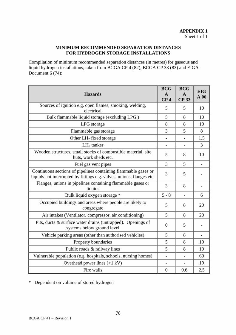
78 BCGA CP 41 – Revision 1
APPENDIX 1
Sheet 1 of 1
MINIMUM RECOMMENDED SEPARATION DISTANCES
FOR HYDROGEN STORAGE INSTALLATIONS
Compilation of minimum recommended separation distances (in metres) for gaseous and
liquid hydrogen installations, taken from BCGA CP 4 (82), BCGA CP 33 (83) and EIGA
Document 6 (74):
Hazards
BCG
A
CP 4
BCG
A
CP 33
EIG
A 06
Sources of ignition e.g. open flames, smoking, welding,
electrical 5 5 10
Bulk flammable liquid storage (excluding LPG.) 5 8 10
LPG storage 8 8 10
Flammable gas storage 3 5 8
Other LH2 fixed storage - - 1.5
LH2 tanker - - 3
Wooden structures, small stocks of combustible material, site
huts, work sheds etc. 5 8 10
Fuel gas vent pipes 3 5 -
Continuous sections of pipelines containing flammable gases or
liquids not interrupted by fittings e.g. valves, unions, flanges etc. 3 5 -
Flanges, unions in pipelines containing flammable gases or
liquids 3 8 -
Bulk liquid oxygen storage * 5 - 8 - 6
Occupied buildings and areas where people are likely to
congregate 5 8 20
Air intakes (Ventilator, compressor, air conditioning) 5 8 20
Pits, ducts & surface water drains (untrapped). Openings of
systems below ground level 0 5 -
Vehicle parking areas (other than authorised vehicles) 5 8 -
Property boundaries 5 8 10
Public roads & railway lines 5 8 10
Vulnerable population (e.g. hospitals, schools, nursing homes) - - 60
Overhead power lines (>1 kV) - - 10
Fire walls 0 0.6 2.5
* Dependent on volume of stored hydrogen

79 BCGA CP 41 – Revision 1
APPENDIX 2
Sheet 1 of 1
MINIMUM RECOMMENDED SEPARATION DISTANCES FOR NATURAL GAS STORAGE INSTALLATIONS
Minimum recommended separation distances (in metres)
Descriptor BCGA
CP 41
BCGA
CP 46 ISO 16923
NOTE 1
ISO 16924 NOTE 1
Recommended
Occupied building or kiosk or where activities are
taking place
4 / 5 / 8 / 20 5 / 15 10 / 15 6, can be reduced
to 3 with DMS NOTE 2
5
Air intakes, compressors, HVAC 5 / 8 / 20 5 / 15 3 5
Pits, ducts, drains, un-trapped 5 5 / 8 5
Parked vehicle (other than being fuelled) 3 / 5 / 8 5 / 8 5
Property boundary 2 / 5 / 8 / 10 5 / 8 5 / 10 5
Public highways railways 5 / 8 / 10 5 / 8 5 5
Overhead power line <1 kV 1.5 1.5
Overhead power line >1 kV 10 10 10 10
Pump dispensing an out of scope liquid fuel HARA NOTE 3
Pump dispensing different in-scope fuel HARA NOTE 3
Pump dispensing same in-scope fuel HARA NOTE 3
NOTES:
1. Standard still under development
2. DMS - Dead Man’s Switch
3. HARA – (in accordance with a) Hazardous Area Risk Assessment.

80 BCGA CP 41 – Revision 1
APPENDIX 3
Sheet 1 of 2
HYDROGEN – GENERAL DATA AND SAFETY CONSIDERATIONS
1. GENERAL DATA
Chemical symbol H2
Flammable / non-flammable Flammable 4 – 75 % in air
Colour Colourless
Odour Odourless
Taste Tasteless
Toxicity Non-toxic
Corrosive Non-corrosive
Lighter / heavier than air Heavier than air when liquid
Lighter than air when gas
Typical physical properties of gaseous hydrogen are:
Gas density 0.085 kg/m3 at 1.013 bar, 15 °C
Typical physical properties of liquid hydrogen are:
Boiling temperature -253 °C at 1.013 bara
Liquid density 0.07 kg/L at 1.013 bara and boiling point
Gas volume of the liquid 830 L gas at 1.1013 bara, 15 oC per 1 L liquid
2. SAFETY CONSIDERATIONS
General considerations for gaseous hydrogen can be found in BCGA CP 4 (82), Appendix 5.
General considerations for liquid hydrogen can be found in BCGA 46 (86) and EIGA
Document 6 (74), which provide general guidance on the principles of storing cryogenic
liquid hydrogen.
The following points are repeated for emphasis:
Liquid hydrogen is a flammable cryogenic liquid at extremely low temperatures
and is cold enough to result in condensation of air, producing oxygen-rich liquid.
Hydrogen is an extremely penetrative gas, which can leak through joints, which
have been proved leak tight with nitrogen, consequently more stringent jointing
techniques such as back-brazing of screwed joints may be necessary.
Although most commonly used materials are suitable with hydrogen, the problem
of embrittlement under cyclic conditions with steel must be considered especially at
elevated temperatures and pressures.

81 BCGA CP 41 – Revision 1
APPENDIX 3
Sheet 2 of 2
A very small amount of energy is required to ignite a flammable cloud of
hydrogen gas. Hydrogen may spontaneously ignite in the event of a leak or in the event
of a relief device opening. Further detail is provided in HSE RR615 (72), Spontaneous
ignition of hydrogen - Literature Review. Hydrogen flames are almost invisible and
produce no radiant heat. The approach to them must be made with caution.
An ignition of 1 kg of hydrogen could result in a release of energy ranging from
0.3 – 30 kg TNT equivalent, dependent upon the confinement of the hydrogen gas.
The use of bursting discs is not recommended on hydrogen systems.
Hydrogen vent lines shall terminate in a safe area at high level. Hydrogen is an
extremely light gas which will readily collect at high level, therefore adequate
ventilation in such places as the roof of a storage room, or the canopy above a
dispenser, is necessary to prevent accumulation of gas which could form a potentially
explosive atmosphere.
Separation distances for hydrogen installations shall take into consideration
vertical distances.
Earth all lines and equipment where there is the possibility of electro-static
discharge.
Electrical equipment and circuits shall be selected, installed, maintained (and
certified where appropriate) in accordance with BS EN 60079 (60).
The storage of hydrogen shall be considered in the site fire risk assessment.
Leaks of flammable fluids present a fire risk and the possibility of a container rupture
due to fire engulfment must be considered. Guidance on DSEAR Risk Assessment is
available in BCGA GN 13 (87).
No hot work shall be performed in the immediate vicinity of the installation
without a Permit to Work.
Pipework shall be purged out of service with inert gas until the residual hydrogen
concentration is below 1 % and purged into service with an inert gas until all residual
oxygen is removed.
Although hydrogen is non-toxic, a hydrogen-enriched atmosphere can cause
asphyxiation through the depletion of oxygen.
Further information on the properties and safe use of hydrogen can be found in:
ISO/TR 15916 (48), Basic considerations for the safety of hydrogen systems.

82 BCGA CP 41 – Revision 1
APPENDIX 4
Sheet 1 of 2
NATURAL GAS – GENERAL DATA AND SAFETY CONSIDERATIONS
1. GENERAL DATA
Methane is the first of the paraffin series of hydrocarbons and is the main constituent of
natural gas.
Chemical symbol CH4
Flammable / non-flammable Flammable 5 – 15 % concentration in air
Colour Colourless
Taste Tasteless
Toxicity Non-toxic
Corrosive Non-corrosive
Odour Odourless in liquid form and gaseous form from high
pressure main
Lighter / heavier than air Heavier than air when liquid or cryogenic gas
Lighter than air when gas is at ambient temperature
Typical physical properties of natural gas are:
Gas density 0.7 kg/m3 at 1.013 bar, 15 °C
Odour Stenched (a stenching agent is added to mains or
compressed natural gas supplies, including gas derived
from LNG)
Typical physical properties of LNG are:
Boiling temperature -162 °C at 1.013 bar
Liquid density 0.44 kg/L at 1.013 bar and boiling point
Gas volume of the liquid 620 L gas at 1.1013 barg, 15 °C per 1 L liquid
Odour Odourless
2. SAFETY CONSIDERATIONS
General considerations for gaseous methane can be found in BCGA CP 4 (82), Appendix 7.
General considerations for LNG can be taken from BCGA CP 46 (86) and ISO 16924 (53)
which provides general guidance on the principles of storing a cryogenic liquid and BS EN
ISO 21009-2 (57) which provides general guidance on the principles of operating a vessel
built to that standard.
The following points are repeated for emphasis:
An ignition of 1 kg of natural gas could result in a release of energy ranging from
0.1 – 10 kg TNT equivalent, dependent upon the confinement of the natural gas.
The use of bursting discs is not recommended on methane systems.
83 BCGA CP 41 – Revision 1
APPENDIX 4
Sheet 2 of 2
Natural gas vent lines shall terminate in a safe area at high level. Natural gas is a
light gas which will readily collect at high level, therefore adequate ventilation in such
places as the roof of a storage room is necessary to prevent accumulation of gas which
could form a potentially explosive atmosphere.
Separation distances for natural gas installations shall take into consideration
vertical distances.
Earth all lines and equipment where there is the possibility of electro-static
discharge.
Electrical equipment and circuits shall be selected, installed, maintained (and
certified where appropriate) in accordance with BS EN 60079 (60).
The storage of natural gas shall be considered in the site fire risk assessment.
Leaks of flammable fluids present a fire risk and the possibility of a container rupture
due to fire engulfment must be considered. Guidance on DSEAR (15) Risk Assessment
is available in BCGA GN 13 (87).
No hot work shall be performed in the immediate vicinity of the installation
without a Permit to Work.
Pipework shall be purged out of service with inert gas until the residual methane
concentration is below 1% and purged into service with an inert gas until all residual
oxygen is removed.
Although natural gas is non-toxic, a methane-enriched atmosphere can cause
asphyxiation through the depletion of oxygen.

84 BCGA CP 41 – Revision 1
APPENDIX 5
Sheet 1 of 1
CHECKLIST
FOR APPROVAL TO INSTALL AND OPERATE FILLING STATIONS
Question Comment Yes No N/A Is there an existing
filling station on the
site?
Gaseous vehicle fuels pose a different set of hazards
and risks from normal liquid vehicle fuels – in
general they are light gases and will rise, whereas
liquid fuel vapours are dense and will fall. Thus if
both types of fuels are present on one site, care is
needed to ensure both sets of hazards and risks are
understood and accounted for.
Has the fuel
specification been
agreed?
Fuel standards are still in development, so agreement
on specification essential – suggested as part of
contract.
Is planning consent
required?
Visual implications. Highways approval for ingress
and egress of HGV’s and PSV’s.
Is Hazardous
Substance Planning
consent required?
Dependant on amount of fuel stored onsite.
Is COMAH consent
required?
Dependant on amount of fuel stored onsite.
Has a DSEAR risk
assessment been
completed?
Always required for gaseous vehicle fuels.
NOTE: Gaseous vehicle fuels are lighter than air
and will rise, which invalidates standard DSEAR
assessments for liquid fuels.
Is the Fire Authority
aware?
Highly recommended.
Is CE marking
required?
If the Machinery Directive is applicable, CE
marking of the filling station components is required
whether or not this is used by the station
manufacturer. However, CE assessment against the
PED is not required if the equipment is for use on
the manufacturer’s site.
Is PSSR required?
Always required for gaseous vehicle fuels.
Has a Written Scheme
of Examination been
completed?
Always required for gaseous vehicle fuels
Is PEA consent
required?
Required if petrol is retailed on the site.

British Compressed Gases Association
www.bcga.co.uk