BCGA CODE OF PRACTICE CP 20 Parties can accept no legal liability or responsibility ... 2.4.3...
55
BCGA CODE OF PRACTICE CP 20 BULK LIQUID OXYGEN STORAGE AT PRODUCTION SITES Revision 2 : 2002
Transcript of BCGA CODE OF PRACTICE CP 20 Parties can accept no legal liability or responsibility ... 2.4.3...

BCGA CODE OF PRACTICE CP 20
BULK LIQUID OXYGEN STORAGE AT
PRODUCTION SITES
Revision 2 : 2002

BCGA CP20 Rev 2 © 2002
BCGA CODE OF PRACTICE CP 20
BULK LIQUID OXYGEN STORAGE AT
PRODUCTION SITES
Revision 2 : 2002
Copyright © 2002 by British Compressed Gases
Association. First printed 1990. All rights reserved. No
part of this publication may be reproduced or transmitted in
any form or by any means, electronic or mechanical,
including photocopy, without permission from the
publisher:
BRITISH COMPRESSED GASES ASSOCIATION 4a Mallard Way, Pride Park, Derby,
DE24 8GX
Tel 01332 225120
Website : www.bcga.co.uk
ISSN 0260-4809

BCGA CP20 Rev 2 © 2002
PREFACE
The various publications issued by the British Compressed Gases
Association have the objective of establishing consistency in design,
construction practices and user operational and maintenance
procedures, in order to establish high standards of reliability and safety
in the interests of employers, employees and the general public.
The Association endeavours to compile these documents using the best
sources of information known at the date of issue. The information is
used in good faith and belief in its accuracy. The publications are
intended for use by technically competent persons and their application
does not, therefore, remove the need for technical and managerial
judgement in practical situations and with due regard to local
circumstances, nor do they confer any immunity or exemption from
relevant legal requirements, including by-laws.
The onus of responsibility for their application lies with the user. The
Association, its officers, its members and individual members of any
Working Parties can accept no legal liability or responsibility
whatsoever, howsoever arising, for the consequences of the use or
misuse of the publications.
For the assistance of users, references are given, either in the text or
Appendices, to publications such as British, European and International
Standards and Codes of Practice, and current legislation that may be
applicable. The intention of BCGA is that this document should be read
and used in the context of these references where the subjects have a
bearing on the local application of the processes or operations carried
out by the user.
BCGA’s publications are reviewed, and revised if necessary, at three-
yearly intervals. Readers are advised to check the list of publications on
the Association’s website www.bcga.co.uk to ensure that the copy in
their possession is the current version.

BCGA CP20 Rev 2 © 2002
CONTENTS
Section Page
Terminology & Definitions 1
Introduction 2
Scope 3
1. GENERAL DESIGN CONSIDERATIONS 4
1.1 Properties of Oxygen 4
1.2 Precautions 4
1.2.1 Oxygen Enrichment of the Atmosphere 4
1.2.2 Oil, Grease, Combustible Material and Other Foreign Matter 5
1.2.3 Cleaning for Oxygen Service 5
1.2.4 Embrittlement of Materials 6
1.2.5 Cryogenic Burns 6
1.2.6 Fire Fighting System 6
1.2.7 Hot Work 6
1.2.8 Ignition Sources 7
1.2.9 Insulation Materials 7
1.2.10 Means of Escape 7
1.3 Regulations and Codes 7
1.4 Design of Installation 8
1.4.1 Design & Manufacture of the Tank 8
1.4.2 Tank Inspection (During Manufacture) 8
1.4.3 Pressure Relief Devices 9
1.4.4 Under-pressure Prevention Devices 10
1.4.5 Pits 10
1.4.6 Electrical Equipment 10
1.4.7 Couplings 11
1.4.8 Lighting 11
1.4.9 Pipework 11
1.4.10 Control and Instrumentation 11
1.4.11 Outer Jacket Purge 11

BCGA CP20 Rev 2 © 2002
Section Page
2. LAYOUT OF THE INSTALLATION 11
2.1 General 11
2.2 Safety Distances 12
2.2.1 Basis 12
2.2.2 Definitions and Intentions 12
2.2.3 On-Site Risks 12
2.2.4 Off-Site Risks 13
2.3 Location of Installation 13
2.3.1 Outdoor Installation 13
2.3.2 Protection Against Electrical Hazards 13
2.3.3 Level & Slope 14
2.3.4 Position of Oxygen Vents 14
2.3.5 Vapour Clouds 14
2.3.6 Diversion of Spillage 14
2.3.7 Protection of Other Areas 15
2.4 Liquid Transfer Area 15
2.4.1 Location of Area 15
2.4.2 Construction of Access Apron 15
2.4.3 Control of Tanker Operation 15
2.5 Liquid Transfer Pumps 16
2.6 Isolation Valves 16
2.6.1 Emergency Isolation Valves 16
2.6.2 Secondary Isolation Valves 16
2.6.3 Process Isolation Valves 17
2.7 Foundations 17
3. ACCESS TO THE INSTALLATION 17
3.1 Personnel 17
3.2 Access to Installation Controls 17
3.3 Notices 17

BCGA CP20 Rev 2 © 2002
Section Page
3.3.1 General Precautions 17
3.3.2 Identification of Contents 18
3.3.3 Legibility of Notices 18
3.3.4 Operating and emergency instructions 18
4. TESTING AND COMMISSIONING 18
4.1 Testing of Installation 18
4.1.1 Pressure Test 19
4.1.2 Pressure Relief Devices 19
4.1.3 Under-pressure Prevention Devices 20
4.1.4 Supports 20
4.2 Adjustment of Process Control Devices 20
4.3 Posting of Notices 20
4.4 Commissioning 20
5. OPERATION, INSPECTION AND MAINTENANCE 20
5.1 Operation of the Installation 20
5.2 Periodic Inspection and Maintenance 21
5.2.1 General 21
5.2.2 Tank Installation 21
5.2.3 Inner Vessel 22
5.2.4 Pressure Relief Devices 22
5.2.5 Emergency Isolation Valve(s) 23
5.2.6 Ancillary Equipment 23
5.3 De-commissioning 23
6. TRAINING AND PROTECTION OF PERSONNEL 23
6.1 Training of Personnel 23
6.2 Permit to Work 24
6.3 Entry into Vessels 24
6.4 Emergency Procedures 24

BCGA CP20 Rev 2 © 2002
Section Page
7. REFERENCES 26
APPENDIX 1 TYPICAL BULK STORAGE TANK SYSTEMS 29
APPENDIX 2 HAZARDS FROM OXYGEN ENRICHMENT 33
APPENDIX 3 “BURNS” DUE TO VERY COLD LIQUEFIED GASES 34
APPENDIX 4 PLAN VIEW OF LIQUID TRANSFER AREA, ACCESS
APRON AND TANKER STANDING AREA 36
APPENDIX 5 LEVELS OF LOX STORAGE THAT TRIGGER
LEGISLATIVE REQUIREMENTS 37
APPENDIX 6 SAFETY DISTANCES 38
APPENDIX 7 RELIEF DEVICE INSPECTION, TESTING
AND EXAMINATION 42
HISTORY AND OBJECTIVES OF BCGA 47

BCGA CP20 Rev 2 © 2002
1
TERMINOLOGY & DEFINITIONS
1. Shall: Indicates a mandatory requirement for compliance with this Code of Practice.
2. Should: Indicates a preferred requirement but is not mandatory for compliance with
this Code of Practice.
3. May: Indicates an option available to the user of this Code of Practice.
4. Tank: Indicates an assembly, complete with a piping system, of an inner vessel and an
outer jacket to contain insulation. The insulation space may be at atmospheric pressure,
slightly above atmospheric pressure or subject to a vacuum. See Appendix 1.
5. Vessel: Indicates a pressure vessel which may or may not be insulated.
6. Outer Jacket: Indicates a shell surrounding an inner vessel, the interspace containing
an insulating system e.g. vacuum, granular or fibrous insulant.
7. Access Apron: Indicates an area between the tank and a tanker where the process
operating controls on both tank and tanker are accessible to the operator during
filling/discharging. This area will normally have provision for diverting any liquid
spillage.
8. Liquid Transfer Area: Indicates an area adjacent to the tank which surrounds the
tanker, when the latter is in the filling/discharging position, and which includes the
access apron.
9. Competent Person: The Competent Person should have such practical and theoretical
knowledge and actual experience of the type of plant which he has to examine as will
enable him to detect defects or weaknesses, which it is the purpose of the examination
to discover, and to assess their importance in relation to the strength and function of the
plant. Equivalent levels of knowledge and experience are also required for Competent
Persons engaged in the writing or certifying of Written Schemes of Examination.
10. Examination: Means examination in accordance with the Written Scheme of
Examination as detailed in the Pressure Systems Safety Regulations 2000 (27).
11. Production Site: Is typically where liquid oxygen is produced from an air separation
unit and stored on site.
12. Numerals in brackets refer to References (Section 7).

BCGA CP20 Rev 2 © 2002
2
INTRODUCTION
In 1985 the Industrial Gases Committee (IGC) of the Commission Permanente Internationale
(CPI) published a document (reference 21/85/E (1)) entitled “Bulk Liquid Oxygen Storage at
Production Sites”.
The British Compressed Gases Association (BCGA) has recognised the need to produce an
equivalent Document specifically for the United Kingdom.
This BCGA Document is intended as a Code of Practice for the guidance of UK companies
directly associated with the design, operation and maintenance of bulk liquid oxygen storage
installations. The objective of this Code of Practice is to make reference, where applicable, to
UK legislation and British Standards where these apply to liquid oxygen (LOX) systems and to
take into account the specific practices of the UK industrial gas companies, particularly in
relation to safety distances.
It is recognised that sites operated by industrial gas producers have a level of expertise and
specialist knowledge that is not available to general industrial and other users.
This Code of Practice also supersedes the BOC Ltd/Air Products Ltd joint document “Code of
Practice for the Bulk Storage of Liquid Oxygen at Production Sites” (April 1974 (2)) which
was published in conjunction with HM Factories Inspectorate.
This Code of Practice is based generally on the IGC Document, but in some instances gives
more detailed requirements for the UK.
The BCGA is grateful for the active help and co-operation of the Health and Safety Executive
who provided much valuable data which was used as the basis for Section 2 of this document,
and who also provided comments on much of the text.
With the permission of the IGC, sections of the IGC Document have also been duplicated.
The BCGA wishes to acknowledge the work of the IGC committee which prepared Document
21/85/E.
The increase in recent years in the size of production capacity of Air Separation Plants has lead
to a corresponding increase in the capacity of liquid oxygen storage installations at production
sites. It has therefore become more important to consider at the design stage the potential
hazards associated with liquid oxygen, the consequence and effects on the local environment of
a major release of liquid, and the preventative measures required.
All new storage installations on production sites shall comply with this Code of Practice.
Major modifications for existing production plant LOX storage should also comply with this
Code of Practice, but it is not intended to apply retrospectively to existing production site
storage installations.

BCGA CP20 Rev 2 © 2002
3
SCOPE
A bulk liquid oxygen storage installation on a production site is defined, for the purposes of this
Code of Practice, as the total fixed assembly of liquid storage tank(s) and other equipment such
as pumps, controls and ancillary equipment required to discharge from the storage into
pipelines or to transfer liquid to or from road vehicles. The installation also includes the liquid
transfer area for road vehicles. The facilities for filling rail vehicles are not specifically covered
in this Code of Practice, although the provisions of this Code of Practice generally apply to the
liquid storage part of the rail fill installation.
This Code of Practice covers LOX storage installations on production sites where the storage
installation is connected to the production process plant. Individual vessel capacity for such
storage is normally greater than 200 tonnes of liquid oxygen. However, where the individual
vessel capacity is less than 200 tonnes but the storage installation is connected to the production
process the installation shall also comply with this Code of Practice.
The process systems of the production plant (such as compressors, heat exchangers, distillation
columns and turbo expanders) are specifically excluded from the scope of this Code of Practice,
as are gaseous distribution pipelines and related equipment.
The liquid feed pipeline from the plant into the LOX storage tank shall be considered as part of
the production plant.
For the purposes of this Code of Practice, cluster tanks (i.e. multiple inner vessels in a single
outer jacket) are considered as a single tank whose capacity is the sum of the capacities of the
individual inner vessels. Where the storage contains multiple products (for example oxygen
and nitrogen or argon in the same cluster tank) the relevant BCGA Code of Practice for oxygen
storage shall apply to the installation, as judged on the sum of all the oxygen vessel capacities.
(See Appendix 1).
Pumping systems often form part of the liquid oxygen storage installation. It is recognised that
the design and installation of these pump systems is a complex subject. No detailed
recommendations are given in this Code of Practice but due consideration should be given to:
• the accepted principles of good practice for oxygen service
• the prevention of mal-operation of the pump(s)
• siting the pump(s) to provide personnel protection in the event of an oxygen pump fire
• the use of fire containment shields
• adequate inspection and maintenance procedures.
For centrifugal liquid oxygen pumps, reference should be made to IGC Document 11/82/E
“Code of Practice for the design and operation of centrifugal liquid oxygen pumps” (3).
Where a LOX storage installation on a production site has an individual vessel capacity of less
than 200 tonnes and the storage is not connected to the production process, BCGA Code of
Practice CP 19 “Bulk Liquid Oxygen Storage at Users’ Premises” (4) may be applied to this
installation.
BCGA CP20 Rev 2 © 2002
4
At cylinder filling depots operated by oxygen suppliers, the oxygen storage vessel capacity is
normally less than 200 tonnes. In such cases this Code of Practice on LOX storage on
production sites should only apply when the tank is connected to an oxygen manufacturing
plant. However the provisions in BCGA Code of Practice on Bulk Liquid Oxygen Storage at
Users’ Premises CP 19 (4) in relation to safety distances, periodic inspection and testing and
the liquid transfer area may be applied to such cylinder filling depots.
1. GENERAL DESIGN CONSIDERATIONS
1.1 Properties of Oxygen
Gaseous oxygen is colourless, odourless and tasteless: it is non toxic; it is slightly heavier
than air. It is not flammable but vigorously supports combustion.
Breathing pure oxygen at atmospheric pressure is not dangerous although exposure for
several hours may cause temporary functional disorder to the lungs.
Oxygen content in air Vol % 21
Gas density at 1.013 bar, 15°C kg/m³ 1.36
Boiling temperature at 1.013 bar °C -183
Liquid density at 1.013 bar, -183°C kg/l 1.14
One litre of liquid oxygen gives approximately 850 litres of gas at ambient conditions.
Cold gaseous oxygen is substantially heavier than air and may accumulate in pits and
trenches.
1.2 Precautions
1.2.1 Oxygen Enrichment of the Atmosphere
The atmosphere normally contains 21% by volume of oxygen. Enrichment to
only 23.5% may give rise to a significant increase in the rate of combustion of
burning materials exposed to such an atmosphere.
Many materials, including some common metals, which are not flammable in air,
may burn in oxygen enriched atmospheres when ignited.
Hazards from oxygen enrichment are further explained in Appendix 2. Good
ventilation shall always be provided in areas where liquid oxygen is stored or
transferred.

BCGA CP20 Rev 2 © 2002
5
1.2.2 Oil, Grease, Combustible Material and Other Foreign Matter
Most oils, greases and organic materials constitute a fire or explosion hazard in
oxygen enriched atmospheres and shall not be used on equipment, which is
intended for oxygen service. Only materials acceptable for the particular
oxygen service application may be used.
All equipment for oxygen service shall be specifically designed and prepared.
1.2.3 Cleaning for Oxygen Service
Before putting equipment into service with oxygen, either for the first time or
following maintenance, it is essential that all surfaces which may come into
contact with an oxygen enriched environment are “clean for oxygen service”,
which means: dry and free from any loose or virtually loose constituents, such
as slag, rust, weld residues, blasting materials (shot or grit), and free from
hydrocarbons or other materials incompatible with oxygen. For hydrocarbon
contamination of industrial oxygen systems, a maximum limit of 500 milligrams
per square metre of cleaned surface area is acceptable. Advice on the cleaning
for oxygen systems is given in the following documents:
“Cleaning of Equipment for Oxygen Service - Guidelines” prepared by IGC (5)
gives practical guidance on how to prepare equipment for oxygen service.
BS 6869 gives procedures for ensuring the cleanliness of industrial process,
measurement and control equipment for oxygen service (37).
BS EN 12300 gives information on ensuring cleanliness of vessels for cryogenic
service generally (34).
BCGA Technical Report TR3 (11) gives information about cleaning oxygen
system components without the use of chemical solvents.
The maintenance and assembly of equipment for oxygen service shall be carried
out in clean, oil free conditions. All tools and protective clothing (such as
overalls, gloves and footwear) shall be clean and free of grease and oil. Where
gloves are not used, clean hands are essential.
Degreasing of an installation or parts of it demands the use of a degreasing
agent, which satisfies the following requirements:
• No or slow reaction with oxygen.
• Preferably no or low toxicity.
• Vapour pressure near to atmospheric pressure to keep boil-off vapours to a
minimum.
• Compatible with both materials of installation and materials used to apply
degreasing agent, e.g. hoses, etc.

BCGA CP20 Rev 2 © 2002
6
It is important that all traces of degreasing agents are removed from the system
prior to commissioning with oxygen. Some agents, such as halogenated
solvents, may be non-flammable in air, but can explode in oxygen-enriched
atmospheres, or in liquid oxygen.
Good housekeeping is necessary to prevent contamination by loose debris or
combustibles.
1.2.4 Embrittlement of Materials
Many materials such as carbon steels and plastics are brittle at low temperatures,
and the use of appropriate materials for the service conditions prevailing is
essential.
Metals suitable for liquid oxygen service are 9% nickel steel, 18/8 stainless steel
and other austenitic stainless steels, copper and its alloys and aluminium alloys.
PTFE (polytetrafluoroethylene) is the most widely used plastics material for
sealing purposes in liquid oxygen service but other reinforced plastics are also
used. For further information on materials see BS 5429 (6).
1.2.5 Cryogenic Burns
Severe damage to the skin may be caused by contact with liquid oxygen, cold
gaseous oxygen or with non-insulated pipes or receptacles containing liquid
oxygen. For this reason, gloves and eye protection shall be worn when handling
equipment in liquid or gaseous oxygen service.
All the safety aspects of handling cryogenic liquid oxygen cannot be covered
adequately in this Code of Practice. The reader is therefore referred to the
British Cryoengineering Society publication, “Cryogenics Safety Manual” (7)
for further information.
1.2.6 Fire Fighting System
First aid fire fighting equipment comprising water hose reels and/or dry powder
extinguishers shall be available near a liquid oxygen storage installation. The
type and quantity of the fire fighting equipment depends on the size of the
installation and should be discussed with the fire authorities.
1.2.7 Hot Work
No hot work shall be performed in the vicinity of the installation without a
Permit to Work. (See 6.2).
BCGA CP20 Rev 2 © 2002
7
1.2.8 Ignition Sources
Smoking and open fires shall be prohibited within the minimum distances
specified in Section 2 of this Code of Practice.
For electrical equipment, see 1.4.6.
1.2.9 Insulation Materials
The components used in an insulating system shall be such that the finished
insulation is suitable for oxygen service.
1.2.10 Means of Escape
Installations covered by this Code of Practice storing or having facilities to store
greater than 135 tonnes of liquid oxygen require a Fire Certificate under the
provisions of the Fire Certificates (Special Premises) Regulations 1976 (8)
which are enforced by HSE. The Fire Certificate deals with means of escape in
case of fire, fire warning systems, fire training and similar general fire
precautions matters.
1.3 Regulations and Codes
This Code of Practice describes minimum requirements. All relevant statutory
regulations shall be applied and relevant codes of practice, standards and specifications
shall be taken into account in the designs and installations covered by this Code of
Practice. (See reference list in Section 7).
In certain circumstances liquid oxygen installations will be subject to the Notification of
Installations Handling Hazardous Substances Regulations 1982 (NIHHS) (9) and the
Control of Major Accident Hazards Regulations 1999 (COMAH) (10).
NIHHS applies where the ‘notifiable quantity’ of the relevant substance is 500 tonnes or
more. The ‘notifiable quantity’ includes the amount of the substance liable to be in
storage, in transport on site, in use for the purposes of manufacturing or processing and in
pipelines within 500 m of the site.
Notification shall be sent to the HSE at least three months before commencing the
activity.
The COMAH Regulations require that persons in control of an industrial activity subject
to the Regulations shall at any time be able to demonstrate that the activity is being
operated safely. They place an obligation on such persons to report major accidents
(Regulations 4 and 5).
More stringent requirements contained in regulations 7 to 12 (known as ‘top-tier’
requirements), which apply to only the potentially more hazardous activities, call for the
following:

BCGA CP20 Rev 2 © 2002
8
• A safety report to be sent to the HSE at least three months before
commencement of the activity.
• The preparation of an on-site emergency plan before commencement of the
activity
• Provision of information to the Local Authority (at county or equivalent level),
to enable them to prepare an off-site emergency plan
• Distribution of safety information to the public before commencement of the
activity.
The top-tier requirements of COMAH apply to industrial installations carrying out a
processing operation involving 2,000 tonnes or more of liquid oxygen. In assessing the
2,000 tonnes, account should be taken of the liquid oxygen in on-site storage and on-site
transport associated with the process operation as well as of the quantity in the process
itself.
Appendix 5 summarises the quantities of liquid oxygen stored in relation to legislation.
1.4 Design of Installation
1.4.1 Design and Manufacture of the Tank
Tanks shall be designed, manufactured and installed in accordance with
recognised pressure vessel, storage tank and piping codes (e.g. PD 5500 (12)/
BS 7777 Part 4 (13)/ANSI/ASME B31.3 (14)) and shall comply with the
production site operator’s specifications. Consideration shall be given to the
requirements of The Pressure Equipment Regulations (38) where appropriate.
Tanks shall be designed to withstand wind-loads in accordance with the
appropriate design codes and with BS 6399 Part 2 1997 (15).
1.4.2 Tank Inspection (During Manufacture)
Pressure vessels and storage tanks shall be inspected and approved during
manufacture by a Competent Person.
Butt welds in the inner vessel shall be radiographed in accordance with the
design code.
If required, prior to its first use, a Competent Person shall certify the vessel as
suitable for the duty within defined operating limits for a defined period.
Any modification to the system shall be carried out in accordance with the
applicable design code; some modifications may require consultation with the
vessel supplier.

BCGA CP20 Rev 2 © 2002
9
1.4.3 Pressure Relief Devices
Pressure relief devices shall be provided to prevent over pressure of the inner
vessel. The devices shall be suitable for the prevailing environmental
conditions.
For the protection of the inner vessel a minimum of two independent pressure
relief devices shall be provided. The capacity of each device shall be such that
should one malfunction or be removed for maintenance; the vessel shall be
adequately protected. Both pressure relief devices will normally be in service.
Consideration shall be given to the design of the system to allow isolation of
individual pressure relief devices to facilitate their periodic testing or
replacement.
Methods of isolation are commonly a three-way valve or isolation valve
upstream of each relief device. The system installed shall ensure that the tank is
fully protected at all times.
Three way valves shall be provided with a position indicator showing which
relief devices are on line.
The design relieving capacity of the inner vessel pressure relief system shall
include the worst foreseeable combination of the operational and upset
conditions, e.g.:
• Boil-off rate including loss of vacuum where applicable.
• Flash gas from plant make, from road tankers and pumps recycling
product.
• Malfunction of control valves in pressure raising systems.
• Barometric pressure changes.
The pipes and valves connecting the vessel to pressure relief devices and the
vent piping shall be adequately sized for the flow conditions in accordance with
a relevant code. Excess pressure drop in the upstream system can lead to relief
valve chattering causing reduction in capacity and valve damage.
Vent pipes shall be correctly supported and designed to prevent blockage by ice
and other foreign matter.
Thermal relief devices shall be provided to prevent overpressure in systems
where liquid or cold gas can be trapped.
Relief valves shall be in accordance with a recognised standard, e.g. BS 6759
(16).
Where bursting discs are installed, they shall be in accordance with a recognised
standard, e.g. BS 2915 (17).

BCGA CP20 Rev 2 © 2002
10
Pressure relief devices shall be provided to prevent over-pressure of the outer
jacket.
The devices shall be suitable for the prevailing environmental conditions.
1.4.4 Under-pressure Prevention Devices
Where necessary, the inner vessel shall be equipped with under-pressure
(vacuum) prevention devices to prevent collapse of the vessel by the
development of partial vacuum conditions in the vessel.
Partial vacuum conditions can arise due to excessive liquid withdrawal rates, by
introducing super-cooled product into a partially filled inner vessel or, under
certain conditions, sudden increases in atmospheric pressure. To avoid partial
vacuum conditions, correct operating procedures shall be introduced and
periodic checks made to ensure the under-pressure prevention device is in
working order.
Frequent demands on the vacuum relief valve may give rise to ingress of
excessive quantities of moist air resulting in accumulation of ice and subsequent
blockage of the relief valve piping. Pressure raising coils should be
appropriately sized to prevent regular operation of vacuum relief valves.
1.4.5 Pits
Equipment requiring regular attention or maintenance should not be installed in
pits. Flanged joints and similar sources of potential leakage should also be
avoided in pits. Where pits cannot be avoided, notices shall be positioned,
warning of the hazards of oxygen enrichment and calling as a minimum, for
analysis of the pit atmosphere and an entry permit in writing, to ensure that it is
safe to enter. For further information on oxygen enrichment see IGC document
04/93/E(18). As a minimum, procedures shall comply with the requirements of
the Confined Spaces Regulations 1997 (19).
1.4.6 Electrical Equipment
Flameproof, explosion proof or other forms of classified electrical equipment
are not necessary for oxygen systems since oxygen is not classified as a
flammable gas according to BS EN 60079 Part 14 (20).
Electrical equipment necessary for the installation and installed within the
distance for source of ignition in Section 2 shall be to BSEN 60529(39),
protection class IP 54 or better. For more severe environmental conditions
IP 55 (designed to protect against jets of water) or IP 65 (designed to eliminate
dust and protect against water jets) should be used. Consideration should be
given to earth bonding of the installation pipework. All electrical installation
shall comply with current electrical legislation.

BCGA CP20 Rev 2 © 2002
11
1.4.7 Couplings
Couplings used for the transfer of liquid oxygen shall be non-interchangeable
with those used for other products.
1.4.8 Lighting
Lighting shall be provided of adequate intensity for all working areas so that at
all times operations can be carried out safely. The need for emergency lighting
shall be considered.
1.4.9 Pipework
The pipework shall be marked to identify the product transported. Valves shall
be marked for function where appropriate.
1.4.10 Control and Instrumentation
The installation shall have the following features:
a) Two independent means of indicating high liquid level.
b) Automatic pressure make up.
c) Automatic pressure vent.
d) Pressure indication.
e) High and low pressure alarms.
f) High liquid level alarm.
g) Remote means of shutting off liquid supply into the tank.
1.4.11 Outer Jacket Purge
Non-vacuum insulated jackets shall be provided with a dry nitrogen purge
system to ensure that a positive pressure is maintained at all times and that the
insulation is kept dry and free from ice.
2. LAYOUT OF THE INSTALLATION
2.1 General
The best guarantee for safe operation and prevention of dangerous leakage is the strict
adherence to nationally accepted design and construction codes for storage installations
and to specific routine operating instructions.
The installation shall be sited to minimise risk to personnel, local population and
property. Consideration shall be given to the location of any potentially hazardous
processes in the vicinity, which could jeopardise the integrity of the storage installation.

BCGA CP20 Rev 2 © 2002
12
An installation may, because of its size or strategic location, come within the scope of
specific legislation for planning controls. The siting of any such proposed installation
shall be discussed and agreed with the local authority and the appropriate sections of the
Health and Safety Executive.
2.2 Safety Distances
2.2.1 Basis
The safety distances given in Appendix 6 are based on experience and
calculations of minor releases and are not intended to protect against
catastrophic failure of the liquid storage vessel. This philosophy is supported by
previous operating history.
2.2.2 Definitions and Intentions
Safety distances are defined as the distance from the exposure to:
a) Any point on the storage system where in normal operation oxygen
leakage or spillages can occur (eg hose couplings, relief valve vents,
etc.), or
b) The tank outer jacket, or
c) The tank nozzle or fill connections
whichever gives the greater distance to the storage tank.
Safety distances are intended to:
a) Protect personnel from exposure to oxygen enriched atmosphere or
cryogenic burns (see also Appendix 3) and to prevent fire enhancement
in the event of the release of liquid oxygen, and
b) Protect the installation from the effect of thermal radiation or jet flame
impingement from fire hazards.
These distances are based on the oxygen storage pressure, ground roughness,
likely weather conditions and an assumed vapour cloud release rate from the
maximum diameter of liquid phase pipework on the storage installation and take
into account site topography and provision for containment or diversion of the
liquid spillage.
The safety distances quoted are based on calculations provided by the Health &
Safety Executive using SRD programme CRUNCH.
2.2.3 On-Site Risks
The safety distances given in Appendix 6 Figure 1 are intended to protect
storage installations, together with personnel and the environment within the
site boundary, in conjunction with the following precautions:

BCGA CP20 Rev 2 © 2002
13
• Taking into account topography, containment or diversion of spillage
• Careful siting of storage to allow for likely movement of vapour clouds
• Provision of emergency isolation valves
• Implementation of emergency procedures
• Adequate personnel training.
These distances are the minimum required to give adequate protection against
risks involved in the normal operation of LOX storage installations and shall be
observed. It is recognised that it is not reasonably practicable to define safety
distances, which alone give adequate protection in the event of a continuous
release of liquid oxygen from storage installations.
The distances indicated in Appendix 6 correspond to well-established practice
resulting from 485,000 tank years of service (2000). Should any evidence
become available which indicates that a revision of the safety distances, in this
document, is necessary then such a revision will take place.
Table 1, Table 2 and Table 3 of Appendix 6 may be used for safety distances
both within and outside the site boundary.
2.2.4 Off-Site Risks
To enable the site operator to minimise the risk to the general public and the
environment, it is necessary for each of the likely risks and exposures to be
considered individually, taking into account the package of precautions
provided within the site boundary but recognising that on-site emergency
procedures and personnel training cannot normally be applied outside the site.
Prior to installation of the liquid oxygen storage, the site operator shall provide
proposed separation distance figures to the Health & Safety Executive.
2.3 Location of Installation
2.3.1 Outdoor Installation
All LOX storage installations at production sites shall be situated in the open air
in a well-ventilated position. LOX installations shall not be located inside
buildings.
2.3.2 Protection Against Electrical Hazards
The location shall be chosen so that damage to the installation by electric arcing
from overhead or other cables cannot occur. The storage tank(s) shall be
protected against lightning discharge. BS 6651 (21) should be referred to for
guidance on lightning protection.

BCGA CP20 Rev 2 © 2002
14
2.3.3 Level & Slope
The slope of the ground shall be such as to provide normal surface water
drainage, but shall also take into consideration the prevention of directing
hazardous materials, such as oil, towards the oxygen installation. An oxygen
spillage shall not be directed towards hazardous materials or locations where
people are at risk. Where liquid oxygen storage tanks are required to be
installed at an elevated level, they shall be supported by purpose-designed
structures. Consideration should be given to protecting these structures from
cryogenic spillage.
2.3.4 Position of Oxygen Vents
All oxygen vents including those from relief devices shall be directed so as to
avoid the risk of impingement on personnel, buildings, structural steelwork or
any combustible materials. For the separation distance from fuel gas vents see
Appendix 6, Figure 1.
2.3.5 Vapour Clouds
All cryogenic liquid spillages produce vapour clouds, which are visible. Tests
and calculations show that the extremities of the visible cloud are
non-hazardous.
When siting the installation, due consideration shall be given to the possibility
of the movement of vapour clouds, originating from spillage or venting, which
could be a hazard (decreased visibility, oxygen enrichment). Local wind
conditions and the topography shall be taken into account.
Vapour clouds from releases are generally low lying (typically below waist
height). Such vapour clouds may be quite extensive depending on weather
conditions and persons working below ground or at low level in the vicinity
may be at risk. Guidance on emergency procedures is given in Section 6.4.
Further guidance can be obtained from BCGA documents TR1 “A Method for
Estimating the Off-Site Risks from Bulk Storage of Liquefied Oxygen
R1(LOX)” (22) and TR2 “The Probability of Fatality in Oxygen Enriched
Atmospheres due to Spillage of Liquid Oxygen R2(LOX)” (35).
2.3.6 Diversion of Spillage
The maximum total liquid spillage which may occur due to failures of
associated equipment, other than the main storage tank itself, shall be
determined by reference to the equipment and system of working in use at the
installation.
Provision shall be made to contain the maximum liquid spillage or divert it
towards the safest available area.

BCGA CP20 Rev 2 © 2002
15
The fire-fighting system noted in paragraph 1.2.6 may be used for diverting a
vapour cloud or liquid spillage.
2.3.7 Protection of Other Areas
The site layout shall provide protection from liquid oxygen spillage for
vulnerable areas, such as places where people may congregate, steel structures
and other foundations. This protection may be achieved by the slope of the
ground, provision of kerbs, gulleys or barriers of adequate size.
Drainage systems within the distance specified in Appendix 6 shall be provided
with traps to prevent the ingress of liquid or gaseous oxygen. Un-trapped
drainage systems shall be at least the distance specified in Appendix 6, Figure 1
from the LOX installation.
2.4 Liquid Transfer Area
2.4.1 Location of Area
A road tanker, when in position for filling from or discharging to the
installation, shall be in the open air and not be in a walled enclosure from which
the escape of liquid or heavy vapour is restricted. Tankers should have easy
access to and from the installation at all times. Kerbs or barriers shall be
provided to prevent damage to any part of the installation by the tanker or other
vehicles.
2.4.2 Construction of Access Apron
The access apron is defined on page 1 and shall be constructed and laid out
generally in accordance with Appendix 4. The materials used shall be suitable
for use with oxygen e.g. gravel, concrete, ceramic blocks etc. Asphalt or
hydrocarbon based products shall not be used. The tanker hard-standing is not
normally regarded as part of the access apron.
2.4.3 Control of Tanker Operation
Operating personnel shall have unobstructed freedom of movement between the
tanker and valve controls on the installation at all times.
All tankers shall be provided with a positive means of preventing tow-away
accidents. Such devices shall be ‘fail-safe’ in operation and regular checks on
the operation of such devices shall be included in maintenance procedures.
Operating procedures shall be written to take account of such means.
Reference should be made to the Carriage of Dangerous Goods by Road
Regulations 1996 (23). The vessel shall be adequately protected against over-
pressure from the road tanker Reference EIGA publication 59/98 (36).

BCGA CP20 Rev 2 © 2002
16
2.5 Liquid Transfer Pumps
Ground mounted pumps for the transfer of liquid oxygen from or to the storage tank shall
be designed and installed in accordance with the IGC Document 11/82/E “Code of
Practice for the Design and Operation of Centrifugal Liquid Oxygen Pumps” (3).
This IGC Code of Practice classifies pumps as either high or low duty depending on
design conditions. High duty pumps are designed to operate under more severe
conditions than those for low duty pumps. Fire protection shield(s) shall be provided
adjacent to or around high duty pumps to minimise the potential hazard to personnel and
equipment.
It is not necessary to provide fire protection shields adjacent to or around low duty
pumps.
2.6 Isolation Valves
2.6.1 Emergency Isolation Valves
All bulk storage tanks of 200 tonnes capacity and above, fitted with liquid
withdrawal or pump suction lines of 50mm bore or greater, shall be provided
with an emergency isolation valve. They may be located internally or outside
the tank. Internal location should be applied wherever possible. If externally
located it should be as close as possible to the tank, to prevent the bulk flow of
liquid from the vessel, in the event of a line failure downstream of this valve.
The emergency isolation valve is additional to the normal isolating valve
required for process operation. The emergency isolation valve shall be reliable
and quick acting and shall be capable of operation under conditions of heavy
liquid spillage. The valve shall fail safe in a closed position on failure of
operating power or operating fluid supply. Provision shall be made for operation
from relatively safe point(s) remote from the potential area of flow of leaking
liquid. The locations of the operating points, their purpose and mode of
operation shall be clearly indicated by suitable notices.
Where it is judged that the presence of a liquid pump(s) or other equipment
constitutes a hazard, action shall be taken to protect the emergency valve and its
actuator from the consequences of fire.
2.6.2 Secondary Isolation Valves
All bulk storage vessels for LOX shall be provided with at least two
independent means of isolating the liquid withdrawal or pump suction pipelines.
This can include emergency isolation valves, provided they are designed for
tight shut off, and process isolation valves as specified below.

BCGA CP20 Rev 2 © 2002
17
2.6.3 Process Isolation Valves
Any primary process isolation valve shall be located as close as practical to the
vessel itself, but downstream of any emergency isolation valves. The position of
isolation valves shall be such that they are subject to an acceptable low risk
from damage from external sources. Protection against overpressure must be
installed between any two isolation valves where liquid or cold vapour can be
trapped.
2.7 Foundations
The tank foundation shall be designed to safely withstand the weight of the tank, its
contents and other possible loads resulting from wind, snow, water content during
pressure test etc. Subsidence conditions should be considered where appropriate. Where
necessary, heating shall be provided to prevent ground freezing and frost heave.
3. ACCESS TO THE INSTALLATION
3.1 Personnel
The installation shall be so designed that authorised persons shall have easy access
to and exit from the operating area of the installation at all times.
3.2 Access to Installation Controls
Filling connections and equipment controls shall be located in such a way that easy
access is provided.
Filling connections and associated equipment controls should be located close to each
other. The tank and tanker controls shall be visible and easily accessible from the
operator’s position.
3.3 Notices
3.3.1 General Precautions
Notices shall be clearly displayed so as to be visible at all times on or near the
tank, particularly at access points; the following should be considered:
• LIQUID OXYGEN
• NO SMOKING
• NO HOT WORK
• NO NAKED LIGHTS
• NO STORAGE OF OIL, GREASE OR COMBUSTIBLE MATERIALS
• AUTHORISED PERSONS ONLY

BCGA CP20 Rev 2 © 2002
18
Symbols should be used instead of written notices wherever possible, e.g.:
No
unauthorised
access
Oxidising
Substance
No naked
flames No Smoking
These signs shall comply with the Health & Safety (Safety Signs and Signals)
Regulations 1996 (24) and with BS 5378 “Safety Signs and Colours” Parts 1, 2 &
3 (25).
3.3.2 Identification of Contents
The storage tank should be clearly labelled ‘LIQUID OXYGEN’.
The connection fittings of multi-storage installations or long fill lines shall be
clearly marked with the contents or the chemical symbol in order to avoid
confusion. (See also 1.4.7).
3.3.3 Legibility of Notices
All displayed warning signs and labels shall be legible, visible and up-to-date at
all times.
3.3.4 Operating and Emergency Instructions
Operating and emergency instructions shall be available and understood before
commissioning the installation. (See also 6.4).
These instructions shall be kept legible and up-to-date.
4. TESTING AND COMMISSIONING
4.1 Testing of Installation Prior to testing and commissioning, measures shall be taken to ensure that the subject
systems have been designed and constructed in accordance with recognised pressure
vessel/piping system codes and that all statutory requirements have been met.
These measures will normally take the form of review of drawings of pressure vessels
and piping systems, manufacturing certificates and construction specifications.
BCGA CP20 Rev 2 © 2002
19
Checks shall also be made to ensure that the cleanliness requirements of paragraph 1.2.3
have been met.
In addition, the following tests shall be carried out in accordance with approved
procedures.
4.1.1 Pressure Test
Works manufactured storage tanks and pressure vessels of the installation will
normally already have been tested/inspected in compliance with the relevant
Pressure Vessel Code, in the manufacturer’s workshop, prior to the first
installation. Further pressure tests shall not be carried out on the vessel without
reference to the vessel design documents and tank history.
In order to verify the integrity of the installation, a pressure test shall be carried
out on site-erected vessels/systems in accordance with design codes and
appropriate standards. Precautions shall be taken to prevent excessive pressure in
the system during the test.
Following any hydraulic test, the system/equipment shall be drained, thoroughly
dried out and checked for moisture content. Care should be taken to prevent a
vacuum condition arising in the inner vessel during draining.
Where a pneumatic test is specified, the appropriate safety precautions shall be
taken and nitrogen or dry, oil free air shall be used as the test medium. The
pressure in the system shall be increased gradually up to the test pressure.
Pneumatic pressure testing is potentially hazardous and should be carried out in
accordance with HSE GS4 Safety in Pressure Testing (26).
Any defects found during the testing shall be rectified in an approved manner
and the system then retested.
A leak and function test shall be carried out in accordance with GS4 and at a
pressure in accordance with the applicable code or regulation.
Pressure tests/leak tests shall be witnessed by a Competent Person, and a test
certificate signed and retained in the tank dossier.
4.1.2 Pressure Relief Devices
Relief valves shall have been subjected to a successful functional test and
certified as such. (See Appendix 7).
A check shall be made to ensure that any gagging pins, transit locking
devices/plugs have been removed from pressure relief devices of the inner
vessel, outer jacket and piping systems and that the devices are undamaged, and
seals are intact.

BCGA CP20 Rev 2 © 2002
20
The relief device set pressure (stamped on or attached to each device) shall be
checked to see that it is in accordance with the maximum permissible operating
pressure of the system.
4.1.3 Under-pressure Prevention Devices
A check shall be made to ensure that any transit locking devices have been
removed and that the under-pressure prevention device is undamaged.
4.1.4 Supports
A check shall be made to ensure all relief valve or bursting disc vent lines are
positioned such that any discharge cannot impact on personnel or equipment and
that the valves and vents are properly supported to take into account reaction
forces.
4.2 Adjustment of Process control devices
Process controls shall be adjusted to the required operating conditions of the system and
then be subjected to a functional test.
4.3 Posting of Notices
Notices (see 3.3) shall be posted before putting the installation into service.
4.4 Commissioning
Commissioning shall only be carried out by authorised personnel and in accordance with
a written procedure. (See Section 4.1 for pre-commissioning measures).
5. OPERATION, INSPECTION AND MAINTENANCE
5.1 Operation of the Installation
Only authorised persons shall be allowed to operate the installation. Operating
instructions shall be supplied to operating personnel and shall reflect current operational
practice.
The instructions shall define the safe operating limits of the system and any special
procedures, which may be required to operate the system in an emergency situation. In
general such instructions should be written and presented in a clear concise format.
If, during the operation of the installation, an excursion occurs outside the design or safe
operating limits of the system (e.g. overpressure, rapid temperature change, mechanical
damage, etc.), it shall be recorded in the tank dossier and a programme of inspection shall
be drawn up by a Competent Person and implemented. (See paragraph 5.2.2).

BCGA CP20 Rev 2 © 2002
21
5.2 Periodic Inspection and Maintenance
5.2.1 General
The adoption of the Pressure Systems Safety Regulations 2000 (27) (which will
be referred to as ‘the Regulations’ in this Code of Practice) has introduced
specific requirements covering design, manufacture, installation, operation,
maintenance and examination of pressure systems.
BCGA Code of Practice CP24 (28) details the requirements of the Regulations as
applied to cryogenic liquid storage systems at production sites.
For the purpose of clarification in this document, the terms ‘inspection’, ‘checks’
and ‘regular test’ are activities associated with the normal operation of the
installation.
The term ‘Examination’ means examination in accordance with the Written
Scheme as detailed in the Regulations and CP24.
The site should be inspected regularly to ensure that it is maintained in a proper
condition and that safety distances are respected.
A comprehensive installation dossier shall be held on site. This dossier shall
include:
• Process and instrumentation diagram(s)
• Tank dossier
• Operating instructions
• Written Scheme of Examination
• Maintenance programme.
5.2.2 Tank Installation
An annual external visual inspection should be carried out by a Competent Person
in accordance with a Written Scheme of Examination to confirm the satisfactory
condition of the outer containment jacket and associated exposed pipework,
valves, controls and auxiliary equipment. Periodic examination of the tank
support structure should be carried out where appropriate. When a tank is taken
out of service for modification or maintenance the accessible areas of the tank
including the outer jacket, vessel, pipework, valves, controls and auxiliary
equipment should be examined by a Competent Person prior to re-
commissioning.
Periodic monitoring should be carried out of either the insulation space vacuum or
the composition of the purge gas in the insulation space, to identify the existence
of any inner tank leaks and to confirm the purge is still effective.

BCGA CP20 Rev 2 © 2002
22
The supply of purge gas to large non-vacuum insulated tanks should be checked
periodically to ensure an effective purge is being maintained.
When soil conditions are uncertain, a regular monitoring of the stability of the
tank foundations should be carried out.
5.2.3 Inner Vessel
After manufacture and prior to commissioning, the inner vessel shall be validated
as fit for service for a defined period by a Competent Person (See 1.4.2).
Thereafter the vessel should be revalidated periodically while in service for a
further defined period.
Revalidation should be based on a documentation assessment and an assessment
of the vessel condition.
The documentation assessment should include consideration of the original
design code and amendments which may have occurred in the intervening period,
the history of the vessel in service, experience with similar vessels elsewhere and
any change in operating conditions.
The assessment of the vessel condition should be based on a Written Scheme
agreed by the operator and a Competent Person. This will be influenced by the
documentation assessment, the established periods between revalidation,
foreseeable modes of failure, particular features of the vessel design and contents,
the possible detrimental effects of warming the inner vessel and, contamination.
There are sound technical and operational reasons for not warming up a vessel to
ambient temperature.
The specific revalidation requirements for the vessel and the required frequency
shall be defined and confirmed in writing for inclusion in the tank dossier by the
Competent Person, taking into account the documentation assessment and the
assessment of the vessel condition. This shall equally apply to vessels already in
service prior to the issue of this Code of Practice.
Guidance on assessment is given in BCGA Code of Practice CP25 (29).
5.2.4 Pressure Relief Devices
Requirements for relief device inspection and testing are given in Appendix 7,
which is derived from IGC document 24/83/E (30).
Regular visual inspection of the devices shall be carried out during normal
operation.
Bursting disc elements may deteriorate due to aggressive environments resulting
in their relief pressure rating being reduced. It may therefore be necessary to
replace disc elements in such environments on a planned basis.

BCGA CP20 Rev 2 © 2002
23
5.2.5 Emergency Isolation Valve(s)
Emergency isolation valves should be periodically tested in accordance with a
prescribed procedure to check correct functional operation.
5.2.6 Ancillary Equipment
Ancillary equipment (other than previously detailed) shall be maintained so as to
be safe.
5.3 De-commissioning
When a tank is to be taken out of service, consideration should be given to making a
detailed examination of the inner vessel to assess its condition and, in addition, provide
data for revalidation of similar tanks.
6. TRAINING AND PROTECTION OF PERSONNEL
6.1 Training of Personnel
All personnel directly involved in the commissioning, operation and maintenance of
liquid oxygen storage systems shall be fully informed regarding the hazards associated
with oxygen and oxygen enrichment and be properly trained, as applicable, to operate or
maintain the equipment.
Training shall be arranged to cover those aspects and potential hazards that the particular
operator is likely to encounter.
Training shall cover, but not necessarily be confined to, the following subjects:
• Potential hazards of oxygen
• Site safety regulations
• Emergency procedures
• Use of fire fighting equipment
• Use of protective clothing/apparatus including breathing sets where applicable
• First aid treatment for cryogenic burns.
In addition, individuals shall receive specific training in the activities for which they are
employed.
It is recommended that the training be carried out under a formalised system and that
records be kept of the training given and where possible, some indication of the results
obtained, in order to show where further training is required.
The training programme should make provision for refresher courses on a periodic basis
and for changes of site personnel.

BCGA CP20 Rev 2 © 2002
24
6.2 Permit to Work
Before maintenance is carried out on the installation, a written Permit to Work for the
particular type of work (cold work, hot work, entry of vessel, electrical work, etc.) shall
be issued by an authorised person to the individual(s) carrying out the work.
6.3 Entry into Vessels
Before entering any tank, vessel or interspace during maintenance or decommissioning, it
is essential that the equipment is safe for the work to be carried out. The following
precautions, which are not necessarily all those required, shall be observed and included
as conditions for the issue of the Permit to Work:
• Complete emptying and purging of the vessel contents
• Confirmation that the inner vessel is approximately at ambient temperature
before entry is permitted
• Analysis of the atmosphere in the vessel and/or interspace at several selected
points with a suitable gas detector (probes may be necessary) to ensure that the
oxygen content is in the range 20 to 21%. It may be necessary to measure this
regularly or continuously and to install forced ventilation while work is in
progress
• Complete isolation of the interspace purge lines and of process lines from other
equipment, which may still be in service, by physical disconnection of a section
of pipeline. Blanking discs may be used but they must be of appropriate
material and thickness for the gas pressure in the pipe
• Presence of standby person(s) outside the tank adjacent to the access manhole to
monitor the work in progress and provide assistance in the event of an
emergency
• Use of appropriate safety equipment such as harnesses, protective clothing, fire
extinguishers, etc.
• Availability of rescue equipment (harnesses, self contained breathing apparatus,
winches, radio links, etc.).
The Confined Spaces Regulations 1997 (19) shall be consulted for more detailed
information on this subject.
6.4 Emergency Procedures
Emergency procedures shall be prepared by the site operator to include action to be taken
in the event of spillage of liquid oxygen. (See paragraph 3.3.4). For general guidance on
preparing an emergency plan see HSE booklet HS(G)191 (31). Local emergency services
shall be party to the preparation of the emergency procedures. Works employees likely
to be affected shall know the actions required to minimise the adverse effects of a
spillage. Consideration shall be given to the carrying out of practical exercises.

BCGA CP20 Rev 2 © 2002
25
The following are guidelines, which should be used for formulating emergency
procedures:
• Raise the alarm
• Summon help and emergency services
• Isolate the source of oxygen, if appropriate and where safely possible
• Evacuate all persons from the danger area and seal it off
• Alert the public to possible dangers from vapour clouds in the immediate
vicinity and evacuate when necessary.
After the liquid spillage has been isolated, oxygen enrichment checks should be carried
out in any enclosed areas where the vapour cloud may have entered. This includes
basements, pits and confined spaces.

BCGA CP20 Rev 2 © 2002
26
7. REFERENCES
(1) IGC Document
No 21/85/E*
Bulk liquid oxygen storage at production sites.
(2) HMFI/ Air
Products Ltd/
BOC Ltd
A Code of Practice for the Bulk Storage of Liquid Oxygen
at Production Sites 1974. (Superseded by this document).
(3)
IGC Document
11/82/E*
Code of practice for the design and operation of
centrifugal liquid oxygen pumps.
(4) BCGA
Code CP 19
Bulk liquid oxygen storage at users’ premises.
(5) IGC Document
No 33/86/E *
Cleaning of equipment for oxygen service - Guidelines.
(6) BS 5429 Code of practice for safe operation of small-scale storage
facilities for cryogenic liquids.
(7) ISBN
0 8543 26057
British Cryoengineering Society - Cryogenics Safety
Manual.
(8) SI 2003 : 1976 Fire Certificates (Special Premises) Regulations 1976.
(9) SI 1357 : 1982 The Notification of Installations Handling Hazardous
Substances Regulations 1982.
(10) SI 743 : 1999 Control of Major Accident Hazards Regulations 1999.
(11) BCGA Technical
Report TR3
Replacement substances for the cleaning of oxygen
system components.
(12) PD 5500 Specification for Unfired Fusion Welded Pressure
Vessels.
(13) BS 7777:Part 4 Design and construction of single containment tanks for
the storage of liquid oxygen, liquid nitrogen or liquid
argon.
(14) ANSI/ASME
B31.3
Chemical plant and petroleum refinery piping.
(15) BS 6399 Part 2
Code of practice for wind.
(16) BS 6759 Part 3
Specification for Safety Valves for Process Fluids.

BCGA CP20 Rev 2 © 2002
27
(17) BS 2915 Specification for Bursting Discs and Bursting Disc
Devices.
(18) IGC Document
04/93/E *
Fire Hazards of Oxygen and Oxygen Enriched
Atmospheres.
(19) SI 1713 : 1997
Confined Spaces Regulations 1997.
(20) BS EN 60079 Electrical apparatus for explosive gas atmospheres. Part
14.
(21) BS 6651 Code of Practice for Protection of Structures Against
Lightning.
(22) BCGA Technical
Report (LOX)
TR1
A Method for Estimating the Off-site Risks from Bulk
Storage of Liquefied Oxygen R1 (LOX).
(23) SI 2095 : 1996 The Carriage of Dangerous Goods by Road Regulations
1996.
(24) SI 341 : 1996
Health & Safety (Safety Signs and Signals) Regulations
1996.
(25) BS 5378
Safety Signs and Colours Parts 1, 2 and 3.
(26) HSE GN GS4
Safety in Pressure Testing 1976.
(27) SI 128 : 2000
The Pressure Systems Safety Regulations 2000.
(28) BCGA
Code CP 24
Application of the Pressure Systems Safety Regulations
2000 to Operational Process Plant.
(29) BCGA
Code CP 25
Revalidation of Bulk Liquid Oxygen, Nitrogen, Argon and
Hydrogen Cryogenic Storage Tanks.
(30) IGC Document
24/83/E*
Cryogenic Pressure Vessels - Pressure Protection Devices.
(31) HS(G)191 Emergency Planning for Accidents: COMAH Regs. 1999.
(32) HS (G) 34 Storage of LPG at fixed installations.
(33) LPGA COP 1 Code of Practice – Installation and Maintenance of bulk
LPG at consumers’ premises.
(34) BS EN 12300
Cryogenic vessels: cleanliness for cryogenic service

BCGA CP20 Rev 2 © 2002
28
(35) BCGA Technical
Report TR2
The Probability of Fatality in Oxygen Enriched
Atmospheres due to Spillage of Liquid Oxygen.
(36) IGC Document
59/98*
The prevention of excessive pressure in cryogenic tanks
during filling.
(37) BS 6869 Code of Practice for procedures for ensuring the
cleanliness of industrial process measurement and control
equipment in oxygen service.
(38) SI 2001 : 1999 The Pressure Equipment Regulations 1999.
(39) BS EN
60529:1992
Degrees of protection provided by enclosures.
Legislation generally applicable to storage of LOX at Production Sites:
• Housing and Planning Act 1986 Part iv – Hazardous Substances.
• The Health and Safety at Work etc Act 1974.
• The Factories Act 1961.
• The Offices Shops and Railway Premises Act 1963.
* A European Industrial Gases Association (EIGA) publication prior to 2000
available from:
Publications du Soudage et de ses Applications (PSA)
B.P. 50362
F-95942 Roissy CDG Cedex, France
Tel 00 33 (1) 49 90 36 00 Fax 00 33 (1) 49 90 36 50
Publications, including revisions, from 2000 onwards are obtainable from EIGA
Website: www.eiga.org
e-mail: [email protected]

BCGA CP20 Rev 2 © 2002
29
APPENDIX 1
Sheet 1 of 4
TYPICAL BULK STORAGE TANK SYSTEMS
PURGE GAS
PI
PI
OR SHELL
INSULATION
OUTER JACKET
INNER VESSEL
DEVICE PLATE RELIEF .
1 FLAT BOTTOM TANKS
Large, site-fabricated inner vessel resting on insulant blocks and surrounded by site-
fabricated outer jacket. The inter-space is filled with granular insulant and purged with
inert gas.

BCGA CP20 Rev 2 © 2002
30
APPENDIX 1
Sheet 2 of 4
TYPICAL BULK STORAGE TANK SYSTEMS
PLATE RELIEF . DEVICE
INNER VESSEL
OUTER JACKET
INSULATION
OR SHELL
PURGE GAS
PI
PI
2 CYLINDRICAL AND SPHERICAL BULK
Smaller tanks may be shop-fabricated, larger tanks are site-built. The interspace is filled
with granular insulant and purged with inert gas. This type of storage tank is operated at
higher pressure than the flat-bottom type.

BCGA CP20 Rev 2 © 2002
31
APPENDIX 1
Sheet 3 of 4
TYPICAL BULK STORAGE TANK SYSTEMS
OR SHELL
INSULATION
OUTER JACKET
INNER VESSELS
DEVICE PLATE RELIEF .
3 CLUSTER OR AGGREGATE TANKS
A number of shop-built inner vessels contained within a single site-fabricated outer
jacket. The interspace is filled with granular insulant and purged with inert gas.
Piping arrangements may permit more than one product to be stored within a single
outer jacket. The piping flow sheet is similar to the flow sheet for the flat-bottom type
of tank

BCGA CP20 Rev 2 © 2002
32
APPENDIX 1
Sheet 4 of 4
SCHEMATIC (FLAT BOTTOM TANKS)
-+
PCV
LAH
PAH PAL
PI
LILAH
PRESSURE
INDICATOR
INDICATOR
LEVEL
ATMOSPHERE
VENT TO
TANKER
LIQUID FROM
PUMP RETURN
LIQUID OR GAS
PI
PI
PURGE GAS
INNER JACKET
OUTER JACKET
INSULATION
OR SHELL
10
3
LIQUID FROM
PRODUCTION PLANT
4
21
5
9
8
10
7 6
Large site-fabricated inner vessel resting on insulant blocks, surrounded by site-fabricated
outer jacket. The inter-space is filled with granular insulant and purged with inert gas.
LEGEND
1 Over/under-pressure protection device.
2 Over/under-pressure protection device.
3 Plate-relief device.
4 Pressure control valve.
5 Emergency shut-off valve (internal or external).
6 Pressure raising regulator.
7 Thermal relief valve.
8 Purge gas regulator.
9 Pressure alarm high and pressure alarm low.
10 Level alarm high.

BCGA CP20 Rev 2 © 2002
33
APPENDIX 2
Sheet 1 of 1
HAZARDS FROM OXYGEN ENRICHMENT
Fire Hazards from Oxygen Enrichment
Oxygen reacts with most elements. The initiation, speed, vigour and extent of these reactions
depend in particular upon:
• The concentration, temperature and pressure of the reactants
• Ignition energy and mode of ignition.
Reaction Mechanism
The mechanism of these reactions is complicated and depends, among other things, upon the
nature of the substances concerned, their physical state, geometric configuration, concentration
and manner of ignition. This, too, influences the speed of reaction, which can vary from slow
combustion to an explosion.
Combustibility of Materials
Oxygen enrichment of the atmosphere, even by a few percent, considerably increases the risk
of fire. Materials, which do not burn in air, including fireproofing materials, may burn
vigorously or even spontaneously in enriched air.
Combustion Characteristics
Oxygen enrichment alters considerably the characteristics of combustion.
Materials, which would normally be regarded as harmless, ignite more easily and sparks can
cause fire. The resulting flames are much hotter and are propagated at much greater speed.
Hydrocarbon Oils and Grease
Oil and grease are particularly hazardous in the presence of oxygen as they ignite
spontaneously and burn with explosive violence. They should NEVER be used to lubricate
oxygen or enriched air equipment. Special lubricants, with which oxygen can be used under
certain conditions, are available.
Smoking
Burning accidents, which occur, are normally triggered by the lighting of a cigarette. Therefore
it is impossible to over-emphasise the danger of smoking in oxygen-enriched atmospheres or
where oxygen enrichment can occur. In such areas smoking shall be forbidden.

BCGA CP20 Rev 2 © 2002
34
APPENDIX 3
Sheet 1 of 2
“BURNS” DUE TO VERY COLD LIQUEFIED GASES
The temperature of liquefied gases varies. The boiling points at 1.013 bar, i.e. the temperatures
at which the liquefied gas vaporises, are as follows:
Helium -269°C
Nitrogen -196°C
Argon -186°C
Oxygen -183°C
Ethylene -104°C
Propane - 42°C
General Effect on Tissue
The effect of extreme cold on tissue is to destroy it, a similar end result to that of heat
exposure, and the amount of cold and the duration of contact is therefore crucial. The
destruction of tissue is not so immediately obvious as in the case of burns since pain is absent
in the frozen stage and the tissue, although rigid, keeps its normal shape and is not obviously
destroyed. Pain and destruction become more apparent as thawing occurs. Those who have
had mild frostbite of fingers or toes will have some idea of the pain on re-warming.
Prevention of contact with very cold liquids is vital and those who work in this field must be
aware of the hazard.
Skin Effects
Liquid, vapour or low temperature gas can produce effects on the skin, which will vary in
severity with temperature and the length of exposure. Naked or insufficiently protected parts
of the body coming into contact with un-insulated pipes or vessels may stick fast by virtue of
the freezing of moisture and flesh may be torn in removal. The wearing of wet clothing should
be avoided.
Continued exposure of naked flesh to cold atmospheres can result in frostbite. There usually is
sufficient warning by local pain whilst the freezing action is taking place. Re-warming at 42-
44°C (108-111°F), a temperature equivalent to lukewarm water, is generally sufficient
safeguard against injury.
Effect of Cold on Lungs
Whilst transient and short exposure produces discomfort in breathing, prolonged inhalation of
vapour or cold gas, whether respirable or not, can produce serious effects on the lungs.

BCGA CP20 Rev 2 © 2002
35
APPENDIX 3
Sheet 2 of 2
FIRST AID TREATMENT OF COLD CONTACT BURNS
Flush the affected areas of skin with copious quantities of tepid water, but do not apply any
form of direct heat, e.g. hot water, room heaters, etc. Move casualty to a warm place (about
22°C; 295K). If medical attention is not immediately available, arrange for the casualty to be
transported to hospital without delay.
While waiting for transport:
• Loosen any restrictive clothing.
• Continue to flush the affected areas of skin with copious quantities of tepid water.
• Protect frozen parts with bulky, dry, sterile dressings. Do not apply too tightly so as to
cause restriction of blood circulation.
• Keep the patient warm and at rest.
• Ensure ambulance crew or hospital is advised of details of accident and first aid
treatment already administered.
• Smoking and alcoholic beverages reduce the blood supply to the affected part and should
be avoided.
The above text has been reproduced with the permission of the British Cryoengineering Society
from its “Cryogenics Safety Manual”, Reference No. ISBN 0-8543-26057 (7).

BCGA CP20 Rev 2 © 2002
36
APPENDIX 4
Sheet 1 of 1
PLAN VIEW OF LIQUID TRANSFER AREA,
ACCESS APRON AND TANKER STANDING AREA

BCGA CP20 Rev 2 © 2002
37
APPENDIX 5
Sheet 1 of 1
LEVELS OF LOX STORAGE THAT TRIGGER LEGISLATIVE REQUIREMENTS
Trigger Quantity (te)
135 Fire Certificate (Special Premises) Regulations 1976 (SI 2003) (8).
500 The Notification of Installations Handling Hazardous Substances
Regulations (NIHHS) 1982 (SI 1357) (9).
Any Quantity * Control of Major Accident Hazards Regulations (COMAH) 1999 (SI 1743)
(10).
2000 Reg 7 - 12 (COMAH) Control of Major Accident Hazards Regulations 1999
(SI 1743) (10) .
* All LOX production sites are subject to Regulations 4 and 5 of the Control of Major
Accident Hazards Regulations (COMAH) 1999 (SI 1743) (10).
Basis for Estimating Quantities
For the purposes of the above regulations, the quantity of liquid oxygen on site should be
estimated on the basis of the maximum storage that is possible taking into account the amount
of liquid oxygen in storage tanks, process vessels and pipework. No account shall be taken of
liquid oxygen in vessels used for transport unless it can be considered as storage, i.e. a full
liquid oxygen tanker parked on site overnight is considered to be ‘storage’.
Notification
The notification procedure and the information required is clearly described in the relevant
regulations.

BCGA CP20 Rev 2 © 2002
38
APPENDIX 6 Sheet 1 of 4
FIG 1. SAFETY DISTANCES IN METRES
Distance between oxygen storage tanks above 200 tonnes capacity and typical hazards.
NOTE (1) The safety distances are measured from the exposure to whichever is the lesser of:
a) Any point on the storage system where, in normal operation, leakage or spillage can occur.
b) The tank outer jacket.
c) The vessel nozzles.
NOTE (2) For buildings the distances are measured to the nearest opening: ie door, window, vent etc.
NOTE (3) For tanks of less than 200 tonnes oxygen capacity refer to BCGA Code CP19.

BCGA CP20 Rev 2 © 2002
39
APPENDIX 6 Sheet 2 of 4
TABLE 1: SEPARATION DISTANCES: LIQUEFIED FLAMMABLE GASES,
FLAMMABLE LIQUIDS AND OXYGEN STORAGE
a) LPG Storage
Size of Storage
Separation Distance
Liquid Oxygen
Vessel
LPG Vessels
tonnes
Weight
Capacity
tonnes
Equivalent
Liquid
Capacity
m³ at 15°C
Metres
Above 200
0 - 2
2 - 220
220 and above
0 - 4
4 - 430
430 and above
30.0
45.0
Individual Assessment
Required
LPG cylinders and other liquefied
flammable gas* cylinders above
50 kg total capacity.
7.5
See also HS(G) 34 (32), and LPGA COP 1 (33).
(b) Other Bulk Flammable Liquids and Liquefied Flammable Gases
The separation distances listed above for LPG should apply to the same stored volumes
(m3) of other bulk liquefied flammable gases and may be used for the same stored
volumes (m3) of bulk flammable liquids
#. These distances may be reduced depending on
the nature of the flammable liquid and any protective measures and in these cases an
individual assessment of the proposed location shall be carried out.
* Common examples include: ammonia, hydrogen sulphide and ethylene oxide.
# Common examples include: acetone, methanol, diesel and petrol.
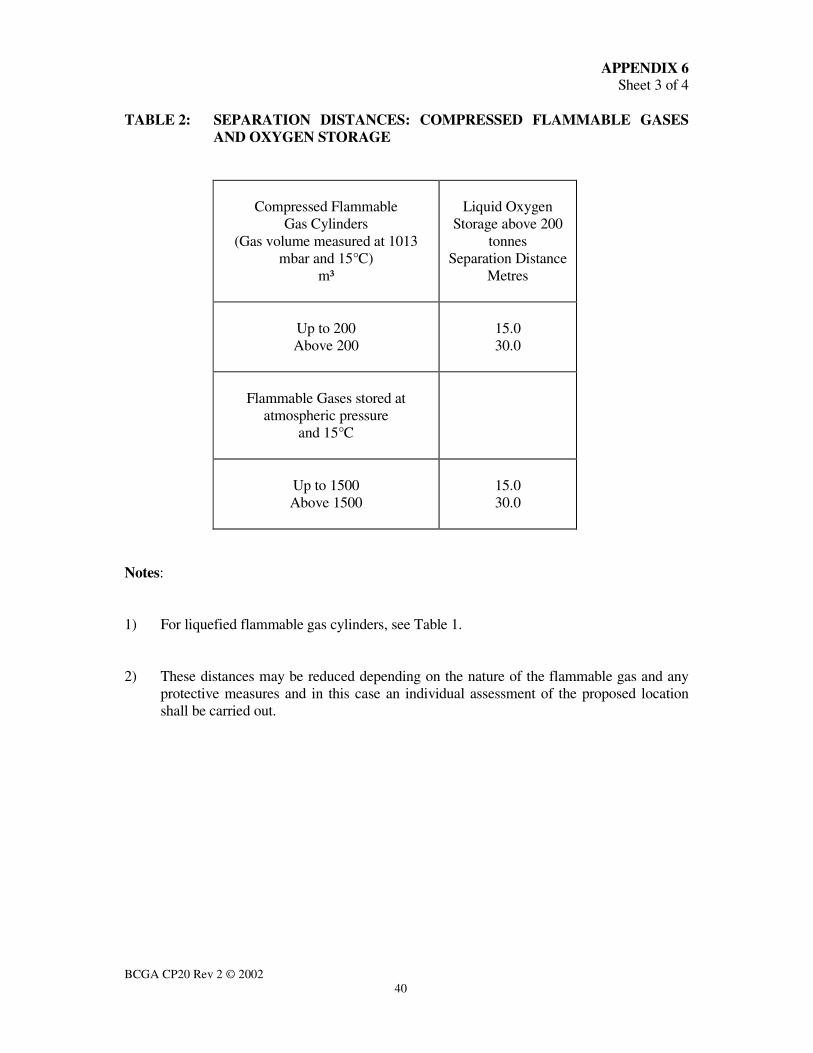
BCGA CP20 Rev 2 © 2002
40
APPENDIX 6 Sheet 3 of 4
TABLE 2: SEPARATION DISTANCES: COMPRESSED FLAMMABLE GASES
AND OXYGEN STORAGE
Compressed Flammable
Gas Cylinders
(Gas volume measured at 1013
mbar and 15°C)
m³
Liquid Oxygen
Storage above 200
tonnes
Separation Distance
Metres
Up to 200
Above 200
15.0
30.0
Flammable Gases stored at
atmospheric pressure
and 15°C
Up to 1500
Above 1500
15.0
30.0
Notes:
1) For liquefied flammable gas cylinders, see Table 1.
2) These distances may be reduced depending on the nature of the flammable gas and any
protective measures and in this case an individual assessment of the proposed location
shall be carried out.

BCGA CP20 Rev 2 © 2002
41
APPENDIX 6 Sheet 4 of 4
TABLE 3: SAFETY DISTANCES FROM FLAMMABLE LIQUID OR GAS LINES
WITH UNION FLANGES ETC TO LOX STORAGE
Flammable Liquid
or
Gas Line Size
(Nominal)
Liquid Oxygen
Storage above 200
Tonnes Separation
Distance
mm
Bore
inches
Bore
Metres
Up to
Above
50
50
2
2
10.0
15.0
Notes:
1. The above separation distances are intended to provide protection for the LOX storage
tank against jet flame impingement from an ignited release from the flammable liquid/gas
line.
2. The distances are based on LPG as the contents of the flammable liquid/gas line and are
given as a ‘worst case’.
3. For flammable liquids or gases other than LPG in the line, the above distances should be
used, unless it can be shown that smaller distances are adequate to avoid jet flame
impingement.
4. If some means of protection from jet flame impingement (such as shielding of the joint
by fire resistive material) can be provided between the union/flange on the flammable
liquid/gas line and the LOX storage and this can be shown to provide an equal or greater
degree of protection than the separation distances shown, the separation distances may be
reduced.
BCGA CP20 Rev 2 © 2002
42
APPENDIX 7 Sheet 1 of 5
RELIEF DEVICE INSPECTION, TESTING AND EXAMINATION
1. INTRODUCTION
The importance of pressure relieving devices (i.e. relief valves and bursting discs) to the
bulk storage installation and their influence on safety cannot be overstressed. The
requirements in paragraph 2 to 4 below shall be complied with for inner vessel relief
devices. Paragraphs 5, 6 and 7 refer respectively to outer jacket and thermal relief
devices and other relief valves associated with the installation.
2. INSPECTION OF INNER VESSEL RELIEF DEVICES PRIOR TO FIRST
FITTING ONTO VESSEL
2.1 Relief valves shall be inspected at the manufacturer’s works or at a suitable testing
station to ensure compliance with the relevant design standard and specification.
Inspection shall be carried out by a competent person independent of the manufacturer to
ensure that:
2.1.1 The valve type, connections and materials are as specified.
2.1.2 The valve set pressure and reseat pressure are witnessed as being correct.
2.1.3 The valve has been properly cleaned for oxygen service.
2.1.4 Supporting certification covering the following is available and correct:
• Materials of construction.
• Strength testing.
• Functional testing to establish set pressure and reseat pressure.
• Limiting operating temperature.
2.1.5 The valve is properly lead sealed to prevent adjustment of the set pressure and
blow-down.
2.1.6 Each valve has a stainless steel plate permanently attached detailing valve make
and type, set pressure, limiting operating temperature, serial number, capacity
and/or orifice size.

BCGA CP20 Rev 2 © 2002
43
APPENDIX 7 Sheet 2 of 5
2.2 Bursting discs shall be verified by selecting representative samples from each production
batch and burst testing to confirm that the rupture pressures are within the stipulated
tolerance. The discs shall be inspected by a competent person independent of the
manufacturer to ensure compliance with the relevant design standard and specification
and that:
2.2.1 Each bursting disc is indelibly marked, tagged or labelled with the tag number,
burst pressure and tolerance at coincident temperature, material and nominal
size.
2.2.2 Each bursting disc holder is marked with the disc material, direction of flow, tag
number and the nominal size and pressure of the disc.
2.2.3 All bursting disc assemblies have been properly cleaned for oxygen service.
2.2.4 Valid certification is available, recording the results of the witnessed burst tests
together with the relevant batch numbers and tag numbers.
3. INSPECTION AFTER FITTING BUT PRIOR TO COMMISSIONING THE
VESSEL
3.1 Visual inspection shall be conducted to ensure that:
3.1.1 Each relieving device is undamaged, in its correct location and properly fitted.
3.1.2 All gagging pins and transit locking devices/plugs, where fitted, are removed.
3.1.3 Relief valve or bursting disc vent lines are directed away from areas frequented
by personnel and from vulnerable items of equipment.
3.1.4 All vent systems are adequately supported.
3.1.5 Each relief device is clearly identified.
3.1.6 Direction of flow is correct.

BCGA CP20 Rev 2 © 2002
44
APPENDIX 7 Sheet 3 of 5
4. PERIODIC IN-SERVICE INSPECTION, TEST AND EXAMINATION
4.1 Pressure relief systems shall be visually inspected at regular intervals, as part of the
normal plant operation. Blockages such as ice or foreign debris shall be removed and
care taken to monitor for seat leakage, corrosion or other visual defects.
Blockages shall be investigated to determine the cause and action to be taken to prevent
recurrence.
If necessary, the relief valve(s) shall be removed and sent to an approved person for
testing, repair and retesting as appropriate. Alternatively the valve shall be removed and
replaced by a valve, which has been inspected in accordance with the requirements
detailed in paragraph 2.1 of this Appendix.
4.2 A Written Scheme for the periodic Examination of relief devices shall be implemented.
Records shall be kept for all inspections and examinations, throughout the operating life
of the pressure system.
It is recommended that reliability data be compiled by ensuring that whenever relief
valves are removed, they are functionally tested to check set pressure and reseat pressure,
prior to disassembly.
4.3 All inspections functional tests and periodic examinations shall be carried out by a
Competent Person who is authorised by the tank owner to carry out such tests.
4.4 All maintenance and repairs of relief devices shall be completed by authorised personnel
who have received adequate training relevant to the make and type of the relief device.
Records shall be maintained to verify the competence of these personnel.
4.5 The recommended minimum frequencies for inspection, test and examination are listed
in the following table:

BCGA CP20 Rev 2 © 2002
45
APPENDIX 7 Sheet 4 of 5
Within each
12 month period
Within each
36 month period
Relief Valves B and (C* or D*) A, B and D
(Requirement of Written Scheme
of Examination)
Pilot Operated Relief Valves B and (C* or D*) A, B and (C or D)
(Requirement of Written Scheme
of Examination)
Vacuum Relief Valves B and (C* or D*) A, B and (C or D)
Bursting Discs B A and B
(Requirement of Written Scheme
of Examination)
* Where local conditions could create problems such as corrosion.
A. THE DEVICE & DOCUMENTATION
This shall include checking of certificates, operational records, specifications,
identification and markings.
B. THE INSTALLATION
This shall include visual inspection of the device, its piping and supports, for corrosion,
leak tightness, identification, test date marking and mechanical integrity.
C. FUNCTIONAL TEST
The relief valve shall be checked to ensure that it lifts at its set pressure and reseats
correctly. The test may be carried out in-situ or on a bench, using a calibrated pressure
gauge.
D. REPLACEMENT OR OVERHAUL
The device shall be replaced by either a new or a fully certified and reconditioned unit or
overhauled in situ.
Should for any reason a relief device be found, on inspection, to be defective or
unsuitable for its purpose, then it shall be renewed or replaced without delay.

BCGA CP20 Rev 2 © 2002
46
APPENDIX 7 Page 5 of 5
5. OUTER JACKET RELIEF DEVICES
Outer jacket relief devices shall be examined prior to fitting to ensure compliance with
the design specification. They shall be periodically examined in accordance with the
approved Written Scheme of Examination. The interval between examinations shall not
exceed 36 months.
6. THERMAL RELIEF VALVES
Thermal relief valves installed to protect pipework shall be examined prior to fitting to
ensure compliance with the design specification. They shall be periodically examined, in
accordance with the approved Written Scheme of Examination. The interval between
examinations shall not exceed 120 months.
7. RELIEF VALVES FOR OTHER DUTIES
Relief valves fitted to other parts of the storage installation shall be examined prior to
fitting to ensure compliance with the design specification. They shall be periodically
examined in accordance with the approved Written Scheme of Examination. The interval
between examinations shall not exceed 72 months.
Note: The frequencies quoted in Sections 4, 5, 6 and 7 above are the minimum
recommended in BCGA Code of Practice 24 (28).

BCGA CP20 Rev 2 © 2002
47
HISTORY AND OBJECTIVES OF BCGA
The British Compressed Gases Association was established in August l971
as the successor to the British Acetylene Association, formed in l901. Its
Members consist of producers, suppliers of gases equipment and container
manufacturers and users operating in the compressed gas field.
The main objective of the Association is the advancement of technology and
safe practice in the manufacture, handling and use of all gases and the design
and manufacture of all containers, apparatus, appliances, plant, etc. BCGA
also provides advice and makes representations, insofar as these relate to
particular problems of the compressed gases industry, on behalf of its
Members to all regulatory bodies, including the UK Government, concerning
legislation both existing and proposed.
Policy is determined by a Council elected from Member Companies, with
detailed technical studies being undertaken by a Technical Committee and its
specialist Sub-Committees appointed for this purpose.
Further details of the Association may be obtained from:
BRITISH COMPRESSED GASES ASSOCIATION 4a Mallard Way, Pride Park, Derby,
DE24 8GX
Tel 01332 225120
Website : www.bcga.co.uk
ISSN 0260-4809