
CO2 progress and issues on the control system Lukasz Zwalinski – PH/DT 09.02.2009.
11
CO2 progress and issues on the control system Lukasz Zwalinski – PH/DT 09.02.2009
-
Upload
bryan-shaw -
Category
Documents
-
view
215 -
download
0
Transcript of CO2 progress and issues on the control system Lukasz Zwalinski – PH/DT 09.02.2009.

CO2progress and issues on the
control system
Lukasz Zwalinski – PH/DT09.02.2009
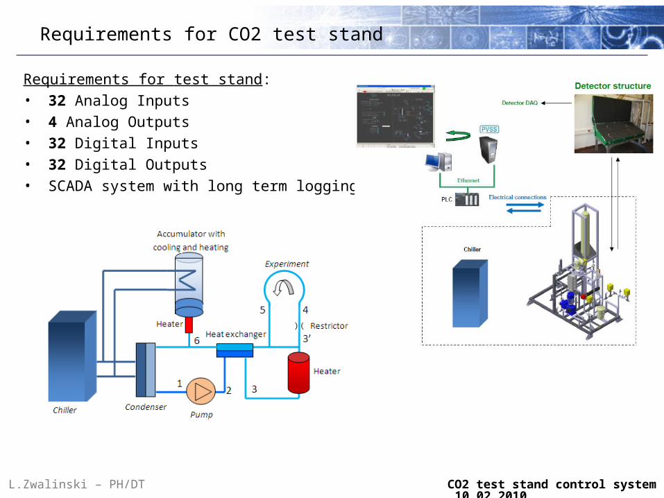
Requirements for test stand:• 32 Analog Inputs • 4 Analog Outputs• 32 Digital Inputs • 32 Digital Outputs• SCADA system with long term logging
Requirements for CO2 test stand
L.Zwalinski – PH/DT CO2 test stand control system 10.02.2010
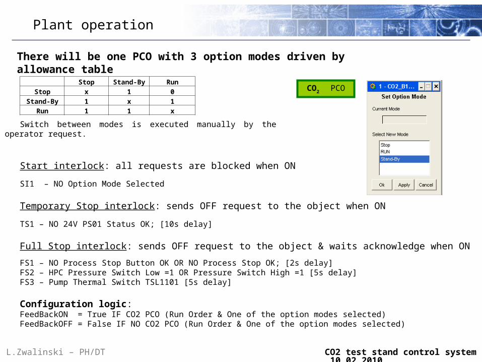
There will be one PCO with 3 option modes driven by allowance table
Plant operation
L.Zwalinski – PH/DT CO2 test stand control system 10.02.2010
Stop Stand-By Run
Stop x 1 0
Stand-By 1 x 1
Run 1 1 x
Switch between modes is executed manually by the operator request.
Start interlock: all requests are blocked when ON
SI1 – NO Option Mode Selected
Temporary Stop interlock: sends OFF request to the object when ON
TS1 – NO 24V PS01 Status OK; [10s delay] Full Stop interlock: sends OFF request to the object & waits acknowledge when ON
FS1 – NO Process Stop Button OK OR NO Process Stop OK; [2s delay] FS2 – HPC Pressure Switch Low =1 OR Pressure Switch High =1 [5s delay] FS3 – Pump Thermal Switch TSL1101 [5s delay]
Configuration logic:FeedBackON = True IF CO2 PCO (Run Order & One of the option modes selected) FeedBackOFF = False IF NO CO2 PCO (Run Order & One of the option modes selected)
CO2 PCO
Plant operation
L.Zwalinski – PH/DT CO2 test stand control system 10.02.2010
2
Start up1
CO2 PCO
T1
Cool down loop
Safety position
3
0
Cool down accumulator
T2
T0
T0
T0
Start up request
Cool down request
Cool down accumulator request
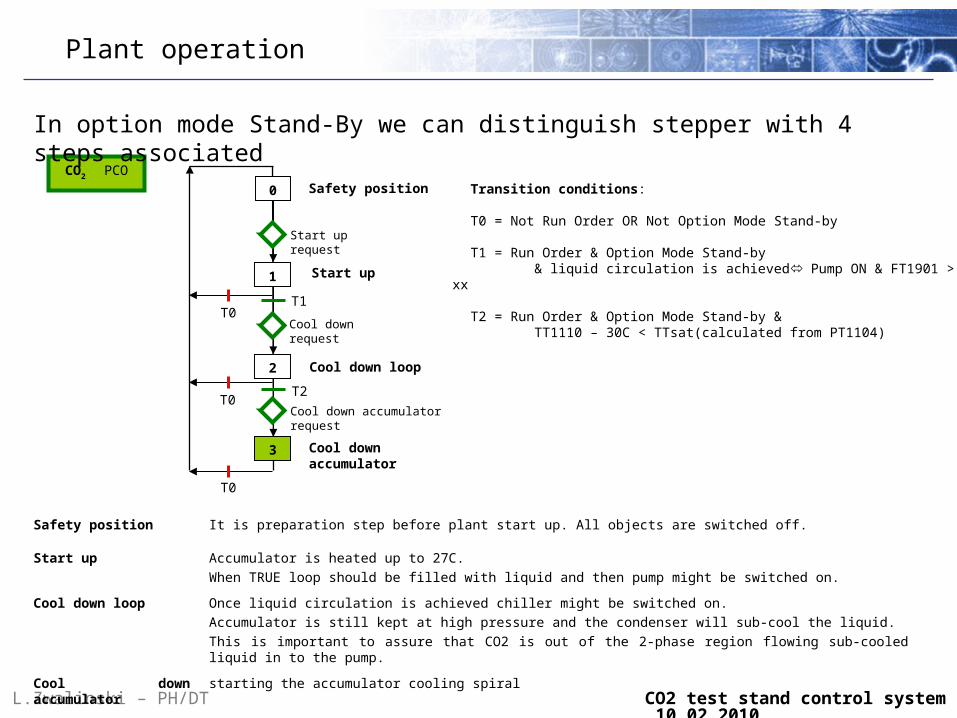
In option mode Stand-By we can distinguish stepper with 4 steps associated
Safety position It is preparation step before plant start up. All objects are switched off.
Start up Accumulator is heated up to 27C.
When TRUE loop should be filled with liquid and then pump might be switched on.
Cool down loop Once liquid circulation is achieved chiller might be switched on.
Accumulator is still kept at high pressure and the condenser will sub-cool the liquid.
This is important to assure that CO2 is out of the 2-phase region flowing sub-cooled liquid in to the pump.
Cool down accumulator starting the accumulator cooling spiral
Transition conditions:
T0 = Not Run Order OR Not Option Mode Stand-by
T1 = Run Order & Option Mode Stand-by & liquid circulation is achieved Pump ON & FT1901
> xx
T2 = Run Order & Option Mode Stand-by & TT1110 – 30C < TTsat(calculated from PT1104)

Accumulator Control
PT1103
Acc. Tsp
PIDMV
SPEH1104
Out High limit
Out Low limit Low limit
High limit
0%
Dynamically calculated f(Rth)0 ÷ 100 %
PID
Out Low limit
Out High limitMV
SP
Psat(Tsp)
CV1104
Low limit
High limit
Dynamically calculated f(sub-cool)0 ÷ -100 %
0%
OutO
OutO
IF > 0 Then EH ONELSE OFF
IF < 0 Then CV ONELSE OFF
Analog Digital Object
Analog Object
PWM
0÷100%
PWM
0÷100%
L.Zwalinski – PH/DT CO2 test stand control system 10.02.2010
Accumulator Control
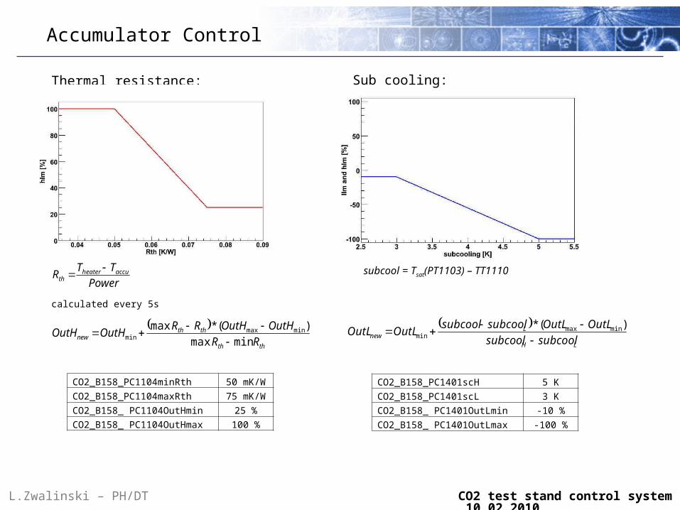
Power
TTR accuheaterth
calculated every 5s
Thermal resistance:
thth
ththnew RR
OutHOutHRROutHOutH
minmax
)(*max minmaxmin
CO2_B158_PC1104minRth 50 mK/WCO2_B158_PC1104maxRth 75 mK/WCO2_B158_ PC1104OutHmin 25 %CO2_B158_ PC1104OutHmax
100 %
subcool = Tsat(PT1103) – TT1110
Sub cooling:
LH
Lnew subcoolsubcool
OutLOutLsubcoolsubcoolOutLOutL
)(* minmax
min
CO2_B158_PC1401scH 5 K
CO2_B158_PC1401scL 3 K
CO2_B158_ PC1401OutLmin -10 %
CO2_B158_ PC1401OutLmax -100 %
L.Zwalinski – PH/DT CO2 test stand control system 10.02.2010

Interlocks
Pump_ST1 IF TT1101 > ? oC Then Pump OFF
Pump_ST2 IF CB_Pump_OK = FALSE Then Pump OFF
HPC_ST1 IF TT1110 < -55oC Then HPC OFF
HPC_ST2 IF (PSL OR PSH) = TRUE Then HPC OFF
HPC_ST3 IF CB_HPC_OK = FALSE Then HPC OFF
EHHPC_ST1 IF CB_EHHPC_OK = FALSE Then EHHPC OFF
EHHPC_ST2 IF HPC.OffST = TRUE Then EHHPC OFF ????
EH1101_ST1 IF CB_EH_OK = FALSE Then Heater OFF
EH1101_ST2 IF TT1101 > threshold Then Heater OFF
EH1102_ST1 IF CB_EH_OK = FALSE Then Heater OFF
EH1102_ST2 IF TT1102 > threshold Then Heater OFF
EH1102_ST3 IF TS = 1 Then Heater OFF
EH1903_ST1 IF CB_EH_OK = FALSE Then Heater OFF
EH1903_ST2 IF TT11## > threshold Then Heater OFF
L.Zwalinski – PH/DT CO2 test stand control system 10.02.2010
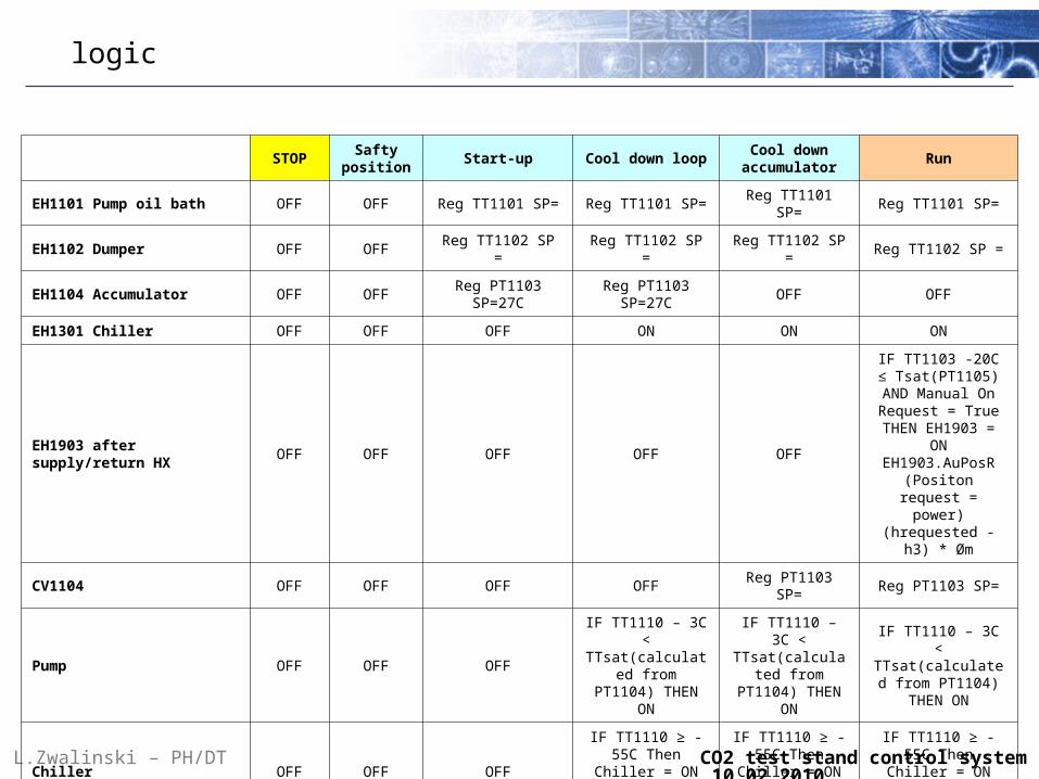
logic
L.Zwalinski – PH/DT CO2 test stand control system 10.02.2010
STOPSafty
positionStart-up Cool down loop
Cool down accumulator
Run
EH1101 Pump oil bath OFF OFF Reg TT1101 SP= Reg TT1101 SP= Reg TT1101 SP= Reg TT1101 SP=
EH1102 Dumper OFF OFF Reg TT1102 SP = Reg TT1102 SP = Reg TT1102 SP = Reg TT1102 SP =
EH1104 Accumulator OFF OFFReg PT1103
SP=27CReg PT1103
SP=27COFF OFF
EH1301 Chiller OFF OFF OFF ON ON ON
EH1903 after supply/return HX OFF OFF OFF OFF OFF
IF TT1103 -20C ≤ Tsat(PT1105) AND Manual On Request
= True THEN EH1903 = ON
EH1903.AuPosR (Positon request =
power) (hrequested - h3) * Øm
CV1104 OFF OFF OFF OFF Reg PT1103 SP= Reg PT1103 SP=
Pump OFF OFF OFF
IF TT1110 – 3C < TTsat(calculated
from PT1104) THEN ON
IF TT1110 – 3C < TTsat(calculated
from PT1104) THEN ON
IF TT1110 – 3C < TTsat(calculated
from PT1104) THEN ON
Chiller OFF OFF OFF
IF TT1110 ≥ -55C Then Chiller = ON Else Chiller = OFF
IF TT1110 ≥ -55C Then Chiller = ON Else Chiller = OFF
IF TT1110 ≥ -55C Then Chiller = ON
Else Chiller = OFF
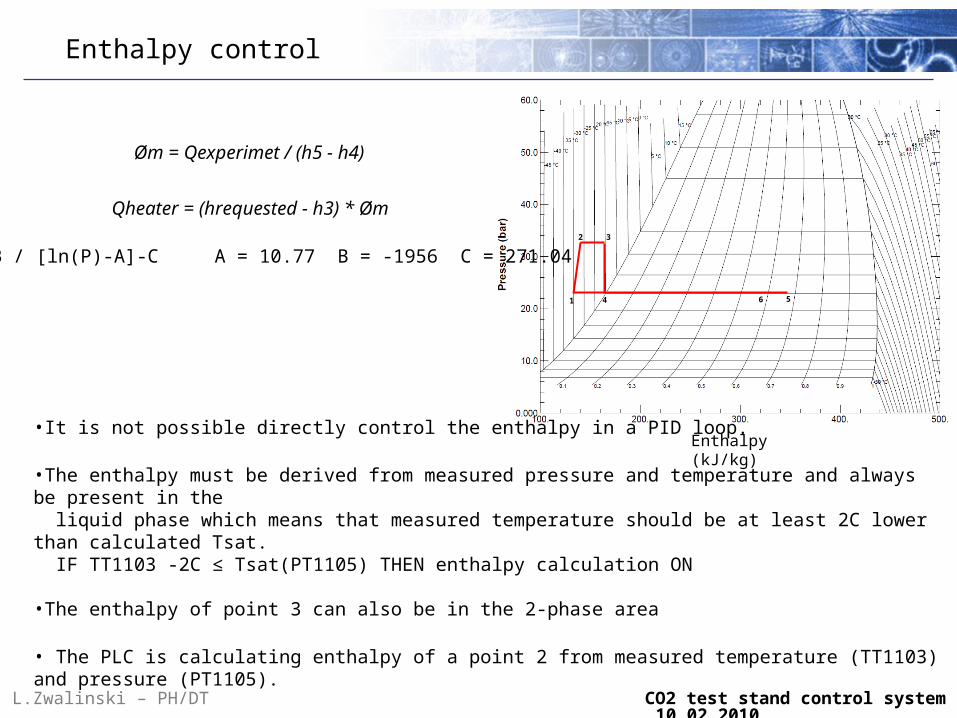
Enthalpy control
Øm = Qexperimet / (h5 - h4)
561 4
2 3
Enthalpy (kJ/kg)
Qheater = (hrequested - h3) * Øm
•It is not possible directly control the enthalpy in a PID loop.
•The enthalpy must be derived from measured pressure and temperature and always be present in the liquid phase which means that measured temperature should be at least 2C lower than calculated Tsat. IF TT1103 -2C ≤ Tsat(PT1105) THEN enthalpy calculation ON
•The enthalpy of point 3 can also be in the 2-phase area
• The PLC is calculating enthalpy of a point 2 from measured temperature (TT1103) and pressure (PT1105).
Tsat = B / [ln(P)-A]-C A = 10.77 B = -1956 C = 271.04
L.Zwalinski – PH/DT CO2 test stand control system 10.02.2010

UNICOS user interface
L.Zwalinski – PH/DT CO2 test stand control system 10.02.2010

Software preparation
SCADA server
Logic Generator
Instance Generator
Specyfication
SIEMENS PLC
UNICOS project creation:
1 – Exel specyfication preparation
2 – PLC hardware configuration
3 – PLC & PVSS instance generation
4 – Process logic programation
5 – Code compilation
6 – Loading to PLC
7 – Commisionig & operation
All generated files will be kept in Subversion Version Control (SVN) service.
L.Zwalinski – PH/DT CO2 test stand control system 10.02.2010