CO CASE FIL - NASA
61
N A S A C O N T R A C T O R REPORT CO cs CNI I NASA CR-2234 C ASE FIL "* ^ • *• THE INFLUENCE OF DEFECTS AND IMPURITIES ON THE NUCLEATION AND GROWTH OF ORIENTED FILMS BY EVAPORATION by A. K. Green Prepared by MICHELSON LABORATORY China Lake, Calif. 93555 for Ames Research Center o NATIONAL AERONAUTICS AND SPACE ADMINISTRATION • WASHINGTON, D. C. • APRIL 1973
Transcript of CO CASE FIL - NASA

N A S A C O N T R A C T O R
R E P O R T
COcsCNI
I
N A S A C R - 2 2 3 4
CASE FIL"* ^ • *•
THE INFLUENCE OFDEFECTS AND IMPURITIES ONTHE NUCLEATION AND GROWTH OFORIENTED FILMS BY EVAPORATION
by A. K. Green
Prepared by
MICHELSON LABORATORY
China Lake, Calif. 93555
for Ames Research Center
o
NATIONAL AERONAUTICS AND SPACE ADMINISTRATION • WASHINGTON, D. C. • APRIL 1973

1 Report No
NASA CR-22342 Government Accession No
4 Title and Subtitle
The Influence of Defects and Impurities on the Nucleationand Growth of Oriented Films by Evaporation
7 Author(s)
A. K. Green
9 Performing Organization Name and Address
Michelson LaboratoryPhysics DivisionChina Lake, California
12 Sponsoring Agency Name and Address
National Aeronautics § Space AdministrationWashington, D.C.
3 Recipient's Catalog No
5 Report DateApril 1973.
6 Performing Organization Code
8 Performing Organization Report No
10 Work Unit No
11 Contract or Grant No
NGR 05-030-001
13 Type of Report and Period Covered
Contractor Report
14. Sponsoring Agency Code
15 Supplementary Notes
16 Abstract
The influence of substrate imperfections on the Nucleation and Growth of fee metals onalkali halides is discussed. Films deposited on well characterized substrates under welldefined vacuum evaporation conditions are investigated. The experimental results of thiswork are correlated with similar work by other investigators. Models which have beenproposed by various authors to explain experimental results are critically examined andareas of difficulty are pointed out.
The influence of defects on nucleation rate and the orientation of the film is emphasized.Specific examples of Impurity effects, Irradiation effects and the Influence of Amorphouslayers are discussed in detail. Evidence is shown that the formation of Multiply TwinnedParticles is a result of coalescence and growth. The only consistent model for the orientinginfluence of impurities is shown to be a chemical rea tion effect. It is demonstrated thatan alkali metal impurity is very likely responsible for the orienting influence of both watervapor exposure and irradiation. A negative result is found for the reported possibility ofan orienting influence being transmitted through an amorphous layer.
17 Key Words (Suggested by Author(s) )Thin FilmsNucleation § GrowthEpitaxyVacuum EvaporationImpurity Effects
19 Security Qassif (of this report)
UNCLASSIFIED
18 Distribution Statement
UNCLASSIFIED-UNLIMITED
20 Security Classif (of this page) 21 No of Pages 22 Price*
UNCLASSIFIED 41 3.00
*For sale by the National Technical Information Service, Springfield, Virginia 22151

TABLE OF CONTENTS
ABSTRACT ,
1.0 INTRODUCTION .
2.0 SUBSTRATE DEFECTS
2.01 Classification ,
2.02 Difficulties of Classification . . . .
2.03 Production and Control of Defects . .
2.04 Defects as Preferred Nucleation Sites
2.05 Orienting Influence of Defects . . . .
3.0 IMPURITY EFFECTS
3.01 Air Exposure (Water Vapor)
3.02 Chlorine Exposure
3.03 Doped Substrates
4.0 INFLUENCE OF IRRADIATION
4.01 Electron Irradiation
4.02 X-Ray Irradiation
4.03 Ion Irradiation
5.0 INFLUENCE OF AMORPHOUS LAYERS
6.0 SUMMARY
ACKNOWLEDGMENTS
REFERENCES
TABLE I
FIGURE CAPTIONS . .
iii

ABSTRACT
The influence of substrate imperfections on the Nucleation and Growth of fee
metals on alkali halides is discussed. Films deposited on well characterized
substrates under well defined vacuum evaporation conditions are investigated.
The experimental results of this work are correlated with similar work by
other investigators. Models which have been proposed by various authors to
explain experimental results are critically examined and areas of difficulty
are pointed out.
The influence of defects on nucleation rate and the orientation of the
film is emphasized. Specific examples of Impurity effects, Irradiation
effects and the Influence of Amorphous layers are discussed in detail. Evi-
dence is shown that the formation of Multiply Twinned Particles is a result
of coalescence and growth. The only consistent model for the orienting
influence of impurities is shown to be a chemical reaction effect. It is
demonstrated that an alkali metal impurity is very likely responsible for
the orienting influence of both water vapor exposure and irradiation. A
negative result is found for the reported possibility of an orienting influ-
ence being transmitted through an amorphous layer.
v

1.0 INTRODUCTION
The work reported here is concerned with the growth of fee metals on alkali
halides. These systems have been used extensively for investigations of
defect and impurity influences and therefore are the most appropriate for
this topic. The growth is characterized by poor wetting of the substrate by
the deposit and the formation of 3-dimensional crystallites in the nucleation
stage of film growth. The growth mechanism has been referred to as the Volmer-
Weber mechanism because of their treatment of similar systems published in
21926. The results discussed here are valid only for systems which exhibit
the V-W growth mechanism.
The decoration of cleavage steps is the most obvious influence of defects
on the formation of metal films evaporated on alkali halide cleavage surfaces.
Figure 1 shows an example of a NaCl surface decorated with Au. This technique,
3as first demonstrated by Bassett, has been very successful at revealing the
4microtopography of the cleavage surface. Bethge has pursued this in detail
and has provided an explanation in terms of the crystal defect structure for
the observed decoration patterns. In Figure 1 we can clearly see linear fea-
tures. Careful analysis of such linear features enabled Bethge to conclude
that the emergence points of the edge dislocations of a tilt boundary were
preferred nucleation sites. In between the line type decoration it is much
more difficult to identify nucleation sites with defects. This is because the
spatial distribution is random and only a careful study of the nucleation
kinetics can distinguish defect from defect-free sites. The work of Robins,

Rhodin and Gerlach with MgO substrates also demonstrates the resolution and
sensitivity of. the nucleation decoration technique for studying surface
defect structure.
2.0 SUBSTRATE DEFECTS
2.01 Classification
We will not limit our discussion simply to the influence of crystallographic
defects but will also consider impurity effects and irradiation effects. For
the purposes of this paper, Figure 2 classifies the types of defects which may
occur on the surface of alkali halide substrates.
A point imperfection is classified as a 0-dimensional defect. Vacancies,
interstitials, F-centers, bulk impurity atoms, adsorbed atoms (of residual gas
or substrate decomposition product) and the emergence point of dislocations
are examples of 0-dimensional defects. Cleavage steps, slip planes which inter-
sect the surface and tilt boundaries are considered as 1-dimensional defects.
Surface layers are classified as 2-dimensional defects, e.g., adsorbed layers,
reaction layers, and intentionally deposited amorphous layers. Precipitates
are also considered as 2-dimensional defects. Because we are just concerned
with surfaces, these classifications differ from the classifications in the
bulk of a crystal where, for example, a grain boundary would be 2-dimensional
and a precipitate would be 3-dimensional; on the surface of the crystal they
are 1- and 2-dimensional, respectively.
2.02 Difficulties of Classification
An unequivocal classification of the defects produced is very difficult in
most cases. For example, water vapor exposure of NaCl is known to result in
the formation of hydroxides. This could be in the form of a continuous or

discontinuous layer (2-dimensional), may exist only on steps (],-dimensional)
or may even form only at specific sites (0-dimensional). Decoration of NaCl
surfaces which have been exposed to water vapor by cleavage in laboratory air
reveals the presence of both 1- and 2-dimensional defects. 0-Dimensional
defects are also produced by water vapor exposure in vacuum after vacuum
cleavage. The same difficulty in classification exists for any gas exposure
whether reactions take place or simply adsorption.
Irradiation-produced defects also present difficulties in classification.
Electron bombardment of alkali halides has been claimed to produce only F-
centers. However, this claim is very likely an oversimplification because
of the experimentally observed buildup of alkali metal on the surface during
bombardment. The alkali may be present in the form of randomly distributed
atoms or in aggregates. Furthermore, the F-center-related vacancies may also
form in aggregates. So a clear unambiguous classification of defects produced
by irradiation is not possible at the present time.
The distribution of impurity atoms resulting from doping is also open to
speculation. Point defects would exist if the dopant atom replaced an atom of
the host material or assumed an interstitial position. Accumulation of dopant
along a planar defect in the bulk would result in a 1-dimensional defect on a
cleavage surface. Aggregates of impurities would result in 2-dimensional
defects.
2.03 Production and Control of Defects
By proper choice of the substrate treatments, however, it is possible to con-
trol the defect structure of the surface to a limited extent. Experimentally,
as already mentioned, the defect structure is best observed by decoration and

a correspondence between defects on one hand and nuclei density and distri-
bution on the other hand is implicit. This correspondence is not simple and
direct. The nucleation rate also depends on other parameters, for example, on
the supersaturation which is a function of the deposition rate and the substrate
temperature. Nucleation can also occur on defect-free sites. The most meaning-
ful results obtained so far are comparative in nature. Two or more substrates
as nearly identical as possible are used simultaneously. One is exposed to
a specific treatment and the other is a control sample. The decoration pro-
ocedure of evaporating less than 5 A of metal is performed simultaneously on
both samples under identical conditions.
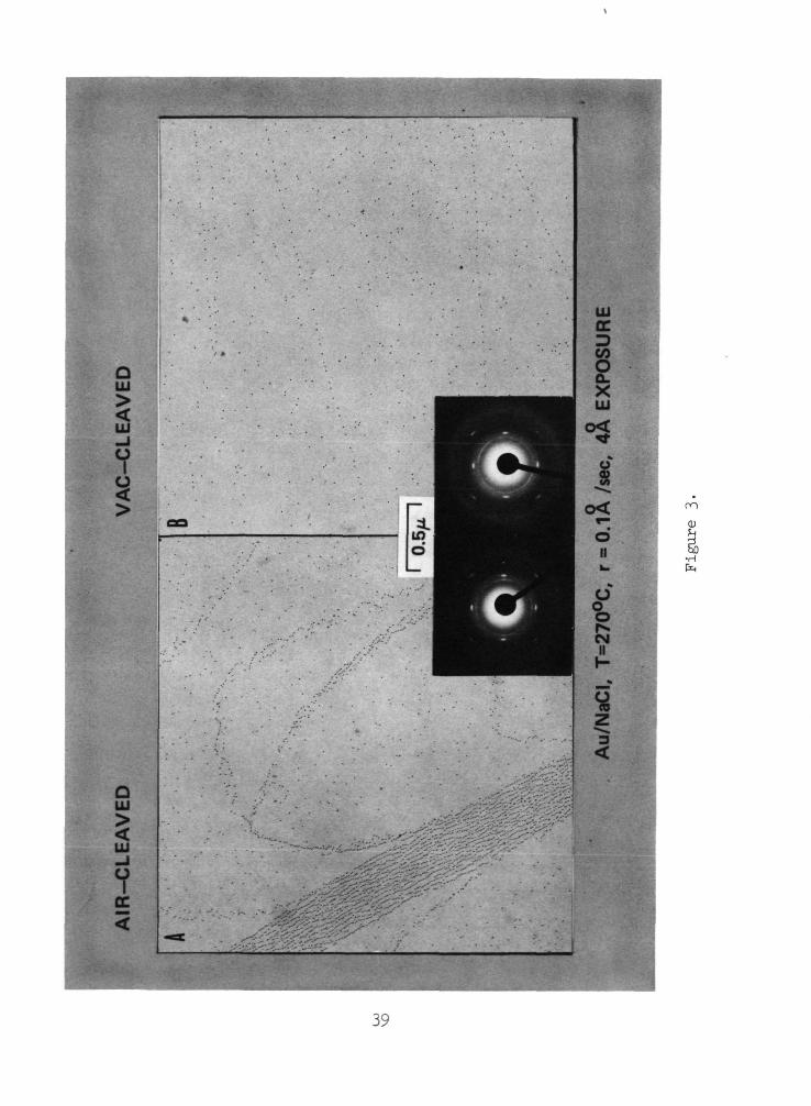
The comparison of air- and vacuum-cleaved surfaces, as seen in Figure 3,
is a typical example of the influence of air exposure on the defect structure
of alkali halides. By cleaving in vacuum the nucleation density is usually
decreased. This effect and its influence on film orientation will be dis-
cussed in detail later. Irradiation by electrons and x-rays have also been
used to introduce defects. Figure 4 shows a comparison of results from an
irradiated area and an unirradiated area of a vacuum-cleaved NaCl surface.
Clearly, the irradiation effect has completely changed the defect structure of
the surface. This complex phenomena, which can significantly affect the parti-
cle orientation as well as the distribution and density, will be discussed as
a separate topic. Some other methods of controlling the defect structure are:
(1) Additively coloring the bulk crystal,
(2) prestressing the bulk crystal,
(3) doping the bulk crystal,
(4) exposing the surface to specific gases, and
(5) accelerating the ions in the depositing vapor beam.
JL04 Defects as Preferred Nucleation Sites
The theoretical treatment of the influence of defects on nucleation is
Q
limited. Cahn in 1957 reported an analysis of the activation energy of
nucleation of a second phase on a dislocation. This treatment used macro-
scopic thermodynamic quantities and the lower limit of validity claimed is
ofor nuclei with 10 A radius. This would mean ^ 130 atoms in the nucleus and
for the systems considered in this discussion is certainly too high. Rhodin
9and Walton have derived an expression for the nucleation rate on point
defects using their atomistic formulation. This has been modified by Frankl
and Venables but only very qualitative agreement with experiment has been
achieved. Recently, a more comprehensive treatment has been given by Stowell
and Hutchinson. This analysis is an extension of Stowell's model of the
nucleation process to include preferential growth sites. Comparison with
experiment is not available at present.
Experimentally, it is found that the density of dislocations on the
surface of alkali halides revealed by etch pit studies is much less than the
4 8 - 2observed nucleation density. For KC1, etch pit densities from 10 to 10 cm
12 10 12 -2have been observed while observed nucleation densities are 10 to 10 cm
When matched cleavage surfaces are used a one-one correspondence of etch pits
13is found. Stirland has attempted to observe a correspondence between nucle-
ation sites on matched cleavage surfaces using the decoration technique. At
T < 150°C there is a correspondence between steps but not between individualS
sites. Above 150°C even the step structure on both cleavage surfaces could not
be correlated.
A correlation between the density of point defects estimated from impurity
content and observed nucleation density of Au on MgO has been reported by
14Robins and Rhodin. They claimed agreement within an order of magnitude
11 -2between the observed saturation density of 3.5 x 10 cm and the surface
+3 +4impurity atom density for either the Fe or Si impurities. However, the
density of the Fe and Si impurities determined from the lowest concentrations
12 -2quoted are each ~ 1 x 10 cm . Their MgO analysis also indicates CaO impur-
13 -2ities of 0.15% which would produce an impurity density of ~ 1 x 10 cm on
the surface. So the density of impurity atoms on the surface is at least two
orders of magnitude higher than the observed saturation nucleation density.
The implication of a one-to-one correspondence between impurity atom sites and
nucleation sites is clearly misleading.
The influence of steps on nucleation has been discussed using macroscopic
thermodynamic concepts in terms of the relative magnitudes of the various sur-
face and interfacial energies involved or in terms of contact angles.
Halpern has treated decoration atomistically using an extension of his
182-dimensional random walk nucleation theory. He concludes that a line defect
will lead to a void border along the line with a width of one-half the diffu-
sion length of a deposit atom on the substrate. A void border along steps is
routinely observed with low evaporation rates for Au/NaCl on both air- and
vacuum-cleaved surfaces. This is easily understood qualitatively, and results
from the depletion of adatoms near the step due to the high density of nucle-
ation sites along the step. The diffusion length of an atom on the surface is
clearly the determining factor for the width of this border.
Qualitatively, the behavior of defects as nucleation sites is understood.
Quantitatively, however, much work remains to be accomplished.

2.05 Orienting Influence of Defects
The enhanced frequency of nucleation on defects Is unquestioned. The orient-
19ing influence of defects, however, is controversial. Palmberg _e_t a]±. have
suggested that the defects on MgO are "tight-binding" sites which promote
20epitaxy. Ueda and Inuzuka have reported that selective nucleation of epi-
taxial crystallites occurs on point defects. They arrived at this conclusion
by comparing the observed nucleation density and orientation of Au on NaCl at
300°C as a function of deposition rate and thickness (< 1.0 A). At very low
rates (0.005 A/sec and 0.04 A/sec) they observed only (100) oriented particles.
oAt higher rates (0.23 A/sec) they observed multiply twinned particles and only
very weak (100) orientation. These observations are consistent with our own
work but we believe the results show that the orientation of the Au crystal-
lites is rate-dependent—not that selective nucleation of epitaxial particles
21occurs on defects. Grvlnbaum and Matthews studied the growth of Au/NaCl on
heavily stepped compared to sparsely stepped surfaces with electron diffrac-
tion and with dark field microscopy. They concluded that steps did not sig-
22nificantly influence the orientation of Au nuclei. Bethge, also using dark
field microscopy, found no influence of either steps or the emergence points
of dislocations on nuclei orientation.
23In contradiction to these results are those of Sato and Shinozaki.
They have studied the particle shape and orientation of Au on NaCl at oneo
temperature (275°C), one thickness (35 A), and at estimated rates between 0.1
andQ.75 A/sec. They observed epitaxial particles preferentially along steps
and attributed the epitaxial orientation of the particles on steps to an
increased interfacial energy resulting from the defect. The fact that theiro
films were in the coalescence stage of formation (35 A average thickness) and

that the rate effect was neglected makes any conclusions about nucleation
24events from their work very questionable. Chopra has added to the confu-
sion here by stating in his book that a defect-free surface will enhance the
adatom mobility and improve the orientation. Because oriented particles are
also observed on steps, Chopra concludes that defects do not alter the orient-
ing influence of the substrate. Sato's conclusions are just the opposite, i.e.,
that the smooth substrate has no orienting influence and that the defect is
responsible for the orientation.
Our own experimental observations have been limited to electron diffrac-
tion and bright field electron microscopy. However, our in situ reflection
electron diffraction work is extremely sensitive to initial orientation and
when coupled with electron microscopy has led us consistently to the conclu-
sion that steps influence particle distribution and size, but not orientation.
The most powerful techniques to study the orientation of individual particles
25have been developed by Poppa and Heinemann. The lattice-imaging method is
the most direct way and they have used this technique to determine not only
the orientation of the epitaxial particle but have also precisely determined
the azimuthal alignment of the particle. By imaging the lattices of both the
deposit particle and the substrate simultaneously, the azimuthal angle can be
determined within 1°. While this method is powerful it is severely limited
for general use because of the difficulty of imaging lattice planes. Another
very elegant technique developed by Poppa and Heinemann is the Bragg Reflex-
Image method. This method uses the fact that a single crystal particle produces
not only a bright field image but also a dark field image that is displaced
from the bright field image by an amount depending upon the defocus of the
objective lens and the specific diffraction angle. In general, by taking two
8

micrographs with a known defocus difference it is possible to determine the
diffracting planes responsible for the "reflex" image. Figure 5 shows the
result of this technique applied to a Au film which has decorated the steps
of a vacuum-cleaved NaCl surface. The film was prepared in our lab and the
micrographs taken by Heinemann. The bright field image on the left
shows the typical step structure. The dark field image on the right is from
the same area with approximately 500 nm defocus. The bright field image is
taken with a normal objective aperture and the dark field image is taken with
an annular aperture which blocks out the primary beam and allows the (111)
and (200) diffracted beams to form the image. The images of nearly all of
the particles in dark field are multiple and have expanded radially. This is
typical for a multiply twinned particle with a (111) basis. Only the parti-
cles marked with an arrow are epitaxial. The particles marked with an elbow
have not been studied sufficiently to be certain but very likely result from
multiple twinning with a (100) basis. Clearly, in this case the steps have
not produced epitaxial particles. The conclusion must be that steps on a
vacuum-cleaved NaCl surface have not influenced the orientation of the
deposited Au particles. The steps are preferred nucleation sites but do not
by themselves determine the orientation.
3.0 IMPURITY EFFECTS
In this section we consider some specific examples of impurity effects. For
this discussion the effect of intentionally contaminating a substrate surface
prior to deposition will be emphasized. Except for our results on the influ-
ence of chlorine, we limit ourselves to growth in a clean vacuum on pretreated
substrates.

3.01 Air Exposure (Water Vapor)
It is a well established result that Au will grow in uhv with parallel epi-
taxial orientation on a NaCl surface which has been cleaved in air but not
on a NaCl surface cleaved in vacuum. Exposure of a vacuum-cleaved surface to
water vapor produces results similar to air exposure; this implies that water
26vapor is the active component in air. Henning has shown, in addition, that
while water vapor is effective, a combination of H_0 and CO. is not. Figure 6
demonstrates again the typically reported differences for the very early stages
of growth of a Au film deposited simultaneously on air- and vacuum-cleaved
NaCl. The decoration features are completely different. Air exposure has
removed the linear step structure and resulted in a surface with preferred
nucleation sites concentrated in river-like bands. The average particle den-
10 -2sity on the air-exposed surface is ~ 5 x 10 cm and on the vacuum-cleaved
9 -2surface is ~ 7 x 10 c« . The particle density on the flat areas is
9 -2~ 7 x 10 cm on both surfaces. The diffraction patterns show a predominant
(100) epitaxial orientation on both surfaces. It must be emphasized that
while these decoration features are characteristic for air- and vacuum-cleaved
surfaces they are not typical for the entire surface. This is especially true
for the vacuum-cleaved surface. The decoration pattern of Figure 6 represents
usually no more than 20% of the entire vacuum-cleaved surface and in some cases
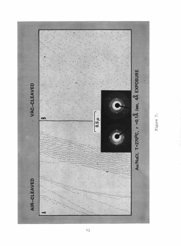
cannot be found at all. A much more typical pattern from the same film is
shown in Figure 7. Here the average particle density is nearly the same (5
10 ~2and 2 x 10 cm air- and vacuum-cleaved, respectively) on both surfaces and
on the flat areas the density is higher on the vacuum-cleaved surface (1 and
10 -22 x 10 cm air- and vacuum-cleaved, respectively). A comparison of the
vacuum-cleaved surfaces in these last two figures shows that the orientation
10

in the early stage of growth is the same on high particle density regions as
it is on low particle density regions. It is also obvious that the orienta-
tion at this early stage of film growth is nearly the same on both the air-
and vacuum-cleaved surfaces.
As mentioned before, we have found this to be a rate-dependent phenomena.
At low rates (< ~ 0.1 A/sec), as demonstrated here, the initial orientation is
(100) with the multiply twinned particles and (111) forming during growth on
the vacuum-cleaved surface. At higher rates, as seen in Figure 8, the multiply
twinned particles and (111) are already observed at this early stage. Evidence
for multiply twinned particles is present on both air- and vacuum-cleaved sur-
faces. The arcs on the (111) and (220) rings are characteristic for multiply
twinned particles.
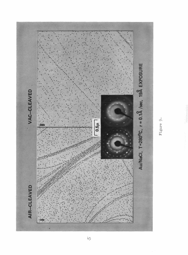
As the film grows thicker the orientation difference between air- and
vacuum-cleaved surfaces increases as seen in Figure 9. At this exposure the
orientation on the vacuum-cleaved surface exhibits strong multiple twinning
and (111) with very weak (100) spots. The particles on the air-cleaved side
have well developed square shapes at this growth stage. A still thicker film,
as seen in Figure 10, continues the trend towards (111) fiber texture on the
vacuum-cleaved surface and (100) parallel orientation on the air-cleaved sur-
face. Notice the well developed crystal shapes on the air-cleaved surface and
the fact that the orientation is as perfect on the flat area as on the high
density river area. Figure 11 demonstrates the results for a continuous or
nearly continuous film. One the air-cleaved surface the orientation has
developed to completely epitaxial while on the vacuum-cleaved surface a two-
degree (111) fiber texture is dominant.
11

As mentioned, this requirement for the existence of impurities to
induce epitaxy has been explained in several ways. There is no doubt that
the air or water vapor exposure produces an impurity layer. The composition
of the layer and the way that it influences the film growth is still contro-
27versial. Harsdorff's model is based on his claim that several layers of
H~0 are adsorbed on the air-cleaved surface. He asserts that the adsorbed
layers lower the substrate-metal interaction, which allows greater mobility
and better orientation. Whether or not greater mobility leads to better
orientation is controversial by itself and the reported evidence for adsorbed
28 29water layers has not been reproduced. Adam has reported the time dependence
of the epitaxial influence of short water vapor exposures of elevated tempera-
tures. The observed disappearance of the orienting influence can as easily
be explained by the desorption or inward diffusion of NaOH as by the removal
23of tLO layers. Sato claims H^O vapor increases interaction energy (less
mobility) and leads to epitaxy in a manner similar to his argument about
30defects. Another mechanism, suggested by Matthews, has been more favorably
received and is often referred to as an explanation for orientation differ-
31 32ences between air- and vacuum-cleaved surfaces. ' This model is based
on the observation that the average particle density is higher on the air-
cleaved surface. Matthews assumes that the growth rate of (111) crystals
is much larger than that of (100) crystals. Consequently, if a film contains
both (111) and (100) particles which are far apart initially, the (111) parti-
cles will become larger than the (100) particles with increasing thickness.
When coalescence occurs the smaller (100) particles will either recrystallize
by diffusion or be converted into twins of the large (111) particles. If
12

coalescence occurs early because of a high particle density, then the (100)
will dominate. The deciding factor for the final orientation according to
this mechanism is the particle density. It is essential for this mechanism
that both (111) and (100) particles exist in the very thin films, even for a
film deposited at low rates and whose transmission electron diffraction pat-
terns only show (100). Matthews claims that this is so and reports that dark
ofield microscopy of 1 A films reveals 10% of the particles are (111) in spite
of the transmission electron diffraction pattern containing no spots from a
(111) orientation.
There are several problems with this model.
1. Most of the (111) particles on the vacuum-cleaved surface do not
have the flat shape assumed by Matthews but are multiply twinned particles.
These particles are sphere-like rather than flat and the lateral growth would
certainly not be faster than that of a (100) cube-like particle. This elimi-
nates the basis of the mechanism.
2. The particle density in between the high density rivers on an air-
cleaved surface is lower than the average particle density on a vacuum-cleaved
surface but the particles in the coalescence stage on this low density area
still develop (100) orientations in contradiction to the model.
3. Attempts to apply the model to other closely related systems, e.g.,
Ag/NaCl, Au/KCl and Ag/KCl are not successful.
32Henning and Vermaak have proposed a model to explain the frequently
reported higher nucleation rate of (100) oriented particles on the water vapor
exposed surface. They use a geometrical argument involving the radii of
overgrowth atoms (r ) and substrate nucleation centers and determine a critical
radiums (r ) required for a perfectly accommodating (100) nucleation center
in terms of the ionic radii of the substrate. If r iso
13

less than r , it is subcritical. The implication is that the nucleation
rate in the supercritical case is higher than for the subcritical case. The
difference in nucleation density on the air- and vacuum-cleaved surfaces fol-
lows from the difference in substrate ionic radii for a clean alkali halide
surface (vacuum cleaved) and a hydroxide surface (air cleaved). Roos and
33Vermaak have attempted to validate this model by studying thick layers of
Au and Ag on NaCl, NaBr, NaF, KC1 and KBr. The model predicts the final ori-
entation in twelve out of twenty cases, if it is assumed that the particles
retain their original orientation during growth and coalescence.
34We have suggested another mechanism based on the observation that air
*5 C O £.
exposure of NaCl produces a hydrate-like surface layer ' containing OH
37ions and possibly CO and CO-. Our mechanism attributes the differences
between growth on air- and vacuum-cleaved surfaces to the coalescence stage.
This mechanism asserts that upon coalescence the resulting particle assumes
a configuration of the lowest free surface and interfacial energy which is
attainable without considerable diffusion. If the anisotropy of surface-free
energy does not change upon coalescence, and if the interaction between parti-
cle and substrate is weak, the resulting particle will have a tendency to be
bound by {111} planes, including the contact plane with the substrate. Thus,
the film tends towards a (111) orientation. If, however, during coalescence
reaction between particle and substrate can occur, and if this leads to a
lowering of the (100) surface and interfacial energy, the average film orien-
tation will tend towards the epitaxial orientation. In applying this mechanism
to the growth of Au on NaCl it is assumed that the air-cleaved surface can
react with Au during coalescence. The impurities which react easily with Au,
e.g., NaOH, are not present on the clean surface and the reaction does not
occur.14

Our model is compatible with the observations but requires that Au can
react with the impurity layer and reduce the surface and interfacial energy
of the (100) plane. Complimentary experiments using in situ reflection elec-
tron diffraction have provided evidence of such reaction products. A complete
understanding of this mechanism and its extension to other systems requires
knowledge of the chemical reactivity and the influence of reaction products
on the surface and interfacial energy of specific planes.
The situation at the present time remains unclear. Each active group has
its own apparently rather fixed ideas in spite of clear contradictions in some
cases. All proposed mechanisms are open to question. Some have been shown to
be clearly wrong while others have not been sufficiently proven.
3.02 Chlorine Exposure
One other extremely active gas for the epitaxial growth of Au and Ag on NaCl•3Q
has been identified. This gas is chlorine; in contrast to water vapoij
chlorine must be present during the growth process for a positive effect on
the orientation. Figure 12 demonstrates the influence of chlorine. These
Au films were deposited under identical conditions, with the exception that a
controlled chlorine leak maintained the pressure at 5 x 10 torr for the
—8film on the right compared to 3 x 10 torr pressure with the chlorine leak
closed. The film grown in the presence of chlorine has a higher coverage and
is perfectly epitaxial as demonstrated by the transmission and reflection
electron diffraction patterns. Figure 13 shows that chlorine is so effective
at inducing epitaxy that it is possible to grow epitaxial films of Au on
vacuum-cleaved NaCl at room temperature in a partial pressure of 5 x 10 torr
ci2.
15

We believe that this is another example of an impurity effect where a
surface layer has lowered the surface and interfacial energy of the (100)
plane and induced epitaxy. The effect is not due to an alteration of the
substrate surface because pre-exposure with chlorine is not effective. All
results point to an influence on the growth and coalescence process. This is
especially obvious for Ag on NaCl where the chlorine exposure can begin after
o75 A of Ag have been deposited and still be effective.
3.03 Doped Substrates
We now consider the published work in which intentionally doped substrates
39were used. Toth and Cicotte have studied the influence of doping NaCl with
calcium. The growth of Au and Ag on air-cleaved NaCl substrates with various
concentrations of calcium chloride (200 ppm, 0.1 and 0.2 mole %) was compared
to the growth on standard grade and high purity NaCl. They found that for
temperatures above 450°C Au will grow epitaxially only in ultrahigh vacuum on
the doped substrates. In normal vacuum (10 torr and poorer) and (111) texture
predominates on the CaCl^-doped NaCl. Similar results were found with Ag at
a temperature of 250°C. In all cases, they observed higher particle densities
on the doped substrates.
We have extended these experiments to include vacuum-cleaved substrates
using 0.2 mole % Ca-doped NaCl obtained from Dr. Toth. As shown in Figure 14,
the particle distribution is nearly the same on both doped and undoped
10 -2 10 -2vacuum-cleaved surfaces (undoped, 9 x 10 cm ; doped, 5 x 10 cm ). This
demonstrates that the particle density influence found by Toth et al. is not
from the doping by itself, but results from changing the interaction of the
doped crystal with air. Figure 15 shows the effect of cleavage in air for a
doped crystal. Here we see that the particle density
16

has increased and that the particle distribution is less uniform on the air-
cleaved surface. An interesting feature is that contrary to the growth of
Au on undoped NaCl, the orientation is definitely not improved by the presence
of the impurity layer resulting from air exposure; this is in spite of the fact
that the particle density is increased.
40Birjega and co-workers have studied the growth of Au films on NaCl
_3doped with 7.5 x 10 mole % Ag. They deposited Au simultaneously on air-
cleaved surfaces of pure NaCl, Ag-doped NaCl and electrolytically colored Ag-
doped NaCl. Their results showed that at 200°C Au grew epitaxially only on
the Ag-doped NaCl which had been electrolytically colored. The electrolytic
coloration is claimed to produce colloidal Ag particles ~ 100 - 200 A. These
authors do not speculate on a specific mechanism responsible for the induced
epitaxy. The colloidal Ag particles may be oriented (Cl- influence) and be
responsible for the orientation.
- 41Sokol and Kosevich have studied the influence of metallic Na and Li on
the growth of Au on additively colored KC1 and NaCl. They placed the alkali
metal into holes drilled in KC1 and NaCl and then heated the crystal to dif-
fuse the alkali into the crystal, producing a concentration gradient. Cleav-
age of the crystal exposed a surface which they describe as containing three
zones of different color, depending on the distance from the alkali metal
source. For Na they observed epitaxial growth of Au within these diffusion
zones of both air- and vacuum-cleaved NaCl. For Li they found improved orien-
tation on an air-cleaved surface. We will have more to say later regarding
the enhancement of epitaxy by the presence of an alkali metal.
14While the MgO used by Robins and Rhodin was not intentionally doped,
it contained a significant concentration of impurities. It was already
17
mentioned that a one-to-one correspondence between impurity atoms and
nucleation density does not occur in this case. In fact, we have compared
the growth on standard optical quality MgO as used by Robins with the growth
on high purity, specially prepared MgO and found no significant difference.
The high purity MgO was obtained from the Research Materials Division of the
Oak Ridge National Laboratory, and was > 99.975% pure compared to a nominal
99.5% for the optical quality.
Obviously, the situation is not understood at the present time. The
work so far has been of a one-shot nature and results are largely inconclusive.
A systematic effort using different dopants and various film substrate combi-
nations under well defined conditions will be required before any general
statements can be made.
4.0 INFLUENCE OF IRRADIATION
A considerable amount of work has been done concerning the influence of
irradiation of alkali halide substrates on the growth of deposited metal films.
Most of the investigations have involved electron irradiation. Some work has
been done with x-rays and some with accelerated ions.
4.01 Electron Irradiation
Electron irradiation during the growth of Au on NaCl produces epitaxial Au
42 A3under conditions that would ordinarily not permit epitaxy. ' Figure 16
demonstrates this effect. In this deposition the specimen was cleaved in
-2vacuum, then one area was irradiated for 15 sec with a 15 kV beam of ~ 1 yA cm ,
the beam was turned off for 30 sec and moved to another area. At the end of
the 30 sec wait the beam was turned on and the shutter opened simultaneously
to expose the entire surface to Au vapor and one area to both electron irra-
diation and Au vapor. The electron beam was turned off after 15 sec and the
shutter closed after 30 sec.18
As seen on the right, the orientation is nearly perfect (100) epitaxy
for the Au film deposited with the electron beam on during the first 15 sec
of deposition. The orientation is predominantly (111) and multiple twinning
on both the nonirradiated and preirradiated surface. The particle distri-
bution is also considerably altered both by the simultaneous irradiation and
by the preirradiation. The particle density is significantly increased by
both simultaneous irradiation and preirradiation.
Continuous films grown under the same conditions are epitaxial on the
simultaneously irradiated area and have a (111) fiber texture on both the
nonirradiated and the preirradiated surfaces. Similar results from simul-
taneously irradiated and nonirradiated surfaces are obtained with KC1, KI,
KBr and LiF. A significant difference observed between the different
systems is that preirradiation is effective in inducing epitaxy for both KBr
and LiF. In fact, for LiF we have observed that the beam influence was still
present after a waiting period of three weeks. The irradiation (two min at
— 2 —9^ 1 yA cm ) was performed at 200°C in a vacuum of 1 x 10 torr and the
specimen then cooled to room temperature. After three weeks the specimen
was heated again to 200°C for the deposition. The preirradiated area exhibited
predominantly (100) epitaxial Au while the nonirradiated area produced (111)
and multiple twinning.
Generally, the experimental results of various workers on the influence of
electron irradiation on epitaxy are quite consistent. However, different models
44have been proposed to explain the observations. The suggestion by Stirland
that the effect results from changes at the substrate caused by irradiation
goes unchallenged. Rhodin and co-workers have been more specific and devel-
oped a model based on preferred nucleation at single atom vacancies produced by
the irradiation. This model is shown schematically in Figure 17. (a) Shows
19

the atomic positions of a NaCl surface with a Cl atom vacancy filled with a
Au atom; (b) shows a four-atom Au nucleus formed at the Cl vacancy; (c) shows
the configuration if a fifth Au atom is added; and (d) shows the minimum
potential energy configuration claimed by Rhodin for the five-atom nucleus.
The argument is very qualitative because the forces between the substrate and
adsorbate are not well enough understood. Their justification for the correct-
45ness of configuration (d) is that a (100) oriented film develops. Stirland
has pointed out that if this model were correct the most likely configuration
would be as shown in (e). This is 45° rotated from the epitaxial azimuthal
alignment and is not observed.
While Rhodin's model is appealing because of its simplicity and apparently
direct approach, it ignores evidence of the very complex phenomena that has43
been observed. We have studied the formation of Au films on NaCl with in
situ reflection electron diffraction and have found direct evidence of Au-Na
compounds. Figure 18 illustrates the development of (100) oriented NaAu_
during the irradiation of a thin Au film. We have also determined that a \
perfectly epitaxial Au film is formed if a continuous film is deposited on top
of the NaAu» compound without additional electron bombardment.
The reflection electron diffraction pattern obtained in situ from all
(100) epitaxial Au films exhibit I/5th streaks. These I/5th streaks can be
interpreted as arising from double scattering between a layer with a NaAu,,
46structure and the (100) Au surface. Palmberg and Rhodin, and somewhat later,
47the group at the University of York—Prutton, Gallon, and co-workers —have
investigated alkali halide surfaces with Auger electron spectroscopy, mass
spectrometry and low energy electron diffraction. Both groups observed time-
dependent stoichiometry changes during electron irradiation leading to an
20

alkali-rich surface layer. Dissociation, sputtering and desorption occur
with irradiation by electrons of energy above 100 eV. The crystallographic
order and the impurities at the surface depend on the alkali halide, the way
in which it was made and its treatment.
48Lord has used shadowed replicas to correlate growth sites with surface
features produced by electron irradiation. He studied Ag on NaF and observed
preferred growth of epitaxial Ag on substrate areas pitted by irradiation.
He suggested that the preferred growth sites and enhanced orientation occurs
on Na-rich areas.
49Gallon and co-workers have reported that simultaneous irradiation and
deposition of Ag on KC1 resulted in K diffusion over the Ag deposit and sug-
gest that this would lead to the formation of interfacial alloys.
Recent work by Lad ' has provided additional evidence, using Electron
Paramagnetic Resonance, that electron irradiation of alkali halides produces
free alkali metal. They have studied both LiF and NaCl. They find that a
constant Li signal is observed in the spectrum from an irradiated LiF sample
for at least a week after irradiation. For NaCl, however, the Na peak decays
rapidly after irradiation (the vapor pressure of Na is ~ 10 times that of Li
at 200°C). This is the same time dependence which we find for the influence
of irradiation on Au films grown on NaCl and on LiF. This agreement between
the lifetime of free alkali metal after irradiation and the influence of irra-
diation on epitaxy is another strong argument for the alkali metal being
responsible for the orientation improvement.
4.02 X-Ray Irradiation
X-rays have also been used to irradiate alkali halide substrates. Inuzuka and
52Ueda have reported that epitaxy is induced by x-ray irradiation of bulk NaCl
21

substrates. The specimens were preirradiated with CuKa for five hr, then
placed in the vacuum system and cleaved prior to deposition. They observed
oa higher particle density and predominant (100) orientation of a 10 A Au film
53deposited at 80°C. Distler also reports an increased particle number and
improved orientation as a result of x-ray irradiation for Au on NaCl. We
have tried repeatedly, without success, to reproduce these claims. Our results
indicate absolutely no orientation influence and little, if any, particle den-
sity influence. Our conclusion is that F-centers by themselves do not influ-
ence orientation and that the effect observed by Inuzuka must result from a
combination of F-centers with some other parameter.
There is one other reported influence of F-centers on film growth. Fors-
54sell and co-workers have used additively colored KBr, KC1 and NaCl substrates.
They observed that at temperatures above 200°C Au films grown on the additively
colored crystals exhibited a higher particle density and improved orientation.
This effect was enhanced at higher temperatures and apparently not observed at
lower temperatures. This temperature dependence would be consistent with
colloid formation. Scott and co-workers have shown that additively colored
crystals form colloids with moderate heating. This suggests that a surface
formed by cleaving a hot additively colored crystal would contain aggregates
of free alkali. The surface defect responsible for the higher nucleation
density and the improved epitaxy is very likely the alkali metal and not the
F-centers.
4.03 Ion IrradiationC /• / O
It has been observed by Mihama and Tanaka and confirmed by our own work,
that acceleration of the ions in the depositing vapor beam will produce a
22

result similar to electron irradiation. Figure 19 illustrates the effect of
placing a screen with -2.5 KV potential in the vapor path. Similar effects
have been observed by depositing high energy ions, ' sputtering and by
43using a Knudsen cell at high positive potential. This enhancement of orien-
tation in all these cases can be explained with the same mechanism as suggested
for electron irradiation. Enhancement of orientation and coalescence by a
transverse electric field has been reported by Chopra ' and more recentlyfi? £ O
by Murayama. ' This effect cannot be explained in terms of surface damage
resulting from energetic particles. The transverse field effect has been
explained as an influence of charged particles on the coalescence process.
It is believed that charged particles would inhibit coalescence and that the
transverse field would remove the charge and produce early coalescence.
It is clear that defects produced by irradiation have a significant effect
on film growth. The nucleation density is definitely increased by irradiation
but this by itself does not induce epitaxy. Atomistic models to explain the
preferred orientation are not satisfactory. We believe that an impurity-
controlled surface energy argument is the only consistent mechanism which will
explain the experimental observations. During the coalescence process the
impurity forms a reaction layer which lowers the surface and interfacial
energy of the (100) surface. For Au on NaCl the reaction compound is NaAu~
as observed by in situ reflection electron diffraction. This mechanism can
also be used to explain the difference in growth on air-cleaved and vacuum-
cleaved surfaces.
23

5.0 INFLUENCE OF AMORPHOUS LAYERS
Distler and co-workers have published a number of papers attempting to
establish a very controversial phenomena. Basically, the claim is that the
surface of a single crystal substrate can be covered with an amorphous layer
without impeding its epitaxial influence. Obviously, this claim is very
pertinent to any discussion of the influence of the interface on film growth.i
We will briefly review the current situation and report the results of ourI
attempt at reproducing it. The explanation of this reported effect by Distler
and co-workers is a long range force |Which is transmitted through the amor-
phous layer. The amorphous layer is Assumed to have replicated the samei
orienting influence which characterized the single crystal substrate. The
long range forces are assumed to result from electrically active centers in
the single crystal substrate. Barna and co-workers have also reported this
effect and claim that the amorphous layer forms an intermediate dielectric
layer which replicates the effective surface potential field of the single
crystal substrate. They claim that the layer acts as an electret and that
the electrical forces at its surface are identical to those at the single crys-
tal substrate and will induce epitaxy in the same way.
We will specifically consider two of Distler's papers. Both report
65results for PbS-C or SiO-NaCl. One published in 1967 and one published in
1971 have significantly identical contents. However, the maximum thickness
used for the intermediate carbon layers decreased from 400 to 70 A in the
five-year period. The thickness of the layer now claimed and the temperature
of the substrate during deposition (> 300°C) make the possibility of holes in
the intermediate layer which expose the single crystal substrate very possible.
24

Figure 20 shows some results which we have obtained for the system PbS
on NaCl with a SiO intermediate layer. The parameters were chosen to repro-
duce Distler's as closely as possible. In the left column we see just the
SiO film with thickness of 20, 40 and 80 A as monitored by a quartz crystal.
These films were not self-supporting and were stabilized with carbon. The
center column shows 40 A PbS films deposited on top of the corresponding SiO
film. The right column shows transmission electron diffraction patterns of
the PbS films. The porous island structure which decorates the NaCl surface
is clearly evident in the SiO film. The PbS films grow quite differently on
different areas of the surface. Large agglomerated particles are typical of
growth on a bare NaCl surface. The higher density and smaller particles are
apparently on the SiO-covered surface. The effect of increasing SiO thickness
on orientation is clearly seen in the transmission electron diffraction
patterns.
Figure 21 shows the results obtained by using both air- and vacuum-
cleaved NaCl and putting down a thicker PbS film. We used 80 A PbS because
we have found that an 80 A film on bare NaCl is completely continuous. There
is no significant difference between the results on air- and vacuum-cleaved
surfaces. The films are composed of a jumble of cube-like particles completely
randomly oriented.
68 69Chopra ' has made a systematic effort to reproduce this effect without
success. Chopra's conclusion was that epitaxy can only occur on the exposed
single crystal surface. Hayek and Schwabe ' have attempted to resolve the
problem. They find that films of C below 10-12 A deposited on NaCl at 250°Ce
contain holes as revealed by Ta-W shadowing and that above 10-12 A thickness
the Distler effect disappears. Hayek and Schwabe evaporated C from two or
25

more directions which would eliminate most of the shadowing effects and may
account for the lower thickness of the amorphous layer at which they found
the orienting influence to disappear. For SiO they have found that at sub-
strate temperatures of 250°C the SiO layer is porous up to 50 A thickness.
72Henning also investigated the phenomena (Au-C-NaCl) and found that on
vacuum-cleaved surfaces the Distler effect could be reproduced but not on an
air-cleaved surface. This can also be understood in terms of holes in the
amorphous layer if carbon, like many other materials, has a lower condensation
coefficient on the vacuum- than on the air-cleaved surface of NaCl. The amor-
phous film formed on vacuum-cleaved NaCl would then have more island structure
and less average thickness than the same thickness exposure on an air-cleaved
surface.
The prospect of the orienting influence of a single crystal substrate
being transmitted through a continuous amorphous layer is certainly exciting
and, if true, would have a profound effect on the view of epitaxy. However,
considering all the published and available reports, it seems very likely
that the effect is not real.
6.0 SUMMARY
Table I summarizes the influence of defects and impurities for the nucleation
stage of Au on NaCl. This system is used because it has been the most thor-
oughly studied. In cases of controversy our own results are used. The diffi-
culties in classification, as mentioned before, must be kept in mind. For
example, vacancies may be aggregates and if so would be more properly classi-
fied as 2-dimensional.
A similar table would be appropriate for the coalescence stage, with the
exception that adsorbed layers can have a positive influence on both number
26

and orientation. The following conclusions stand out from the results
reported here:
1. Neither the density nor the orientation of the initially formed
particles have a determining influence on the final orientation.
2. The particle density on the flat surfaces of air- and vacuum-cleaved
NaCl is the same but the final orientation is very different.
3. Multiply twinned particles form in the early coalescence stage and
their formation as a function of thickness is rate dependent.
A. Specific impurities such as alkali metals and Cl. play a dominant
role in the film orientation.
Clearly, there are many difficult and interesting problems that remain
unsolved. Systematic experiments under very carefully controlled conditions
are necessary to solve these problems.
ACKNOWLEDGMENTS
The author acknowledges, with pleasure, the significant contribution of his
co-workers to the work reported here, especially to Prof. Ernst Bauer for his
motivating influence and assistance. A special recognition is also due to
John Dancy for his expertise with the electron microscope.
27

REFERENCES
1. Ernst Bauer, Z. Krist. 110. 372 (1958).
2. M. Volmer and A. Weber, Z. Physik. Chem. 119. 277 (1926).
3. G. A. Bassett, Phil. Mag. _3» 1042 (1958).
4. H. Bethge, Phys. Stag. Solidi _2, 3 (1962); ibid 2. 775 (1962).
5. J. L. Robins, T. N. Rhodin, and R. L. Gerlach, J. Appl. Phys. 37, 3893 (1966).
6. R. A. Lad, Surf. Sci. 12, 37 (1968) and references quoted therein.
7. T. N. Rhodin, P. W. Palmberg, and C. J. Todd, Molecular Processes on Solid
Surfaces (1969).
8. J. W. Cahn, Acta Met. J>, 169 (1957).
9. T. N. Rhodin and D. Walton, Metal Surfaces, ed. by W. D. Robertson and
M. A. Gjostein (Am. Soc. for Metals, Ohio, 1963), p. 259.
10. D. R. Frankl and J. A. Venables, Adv. in Phys. JL9, 409 (1970).
11. M. J. Stowell and T. E. Hutchinson, Thin Solid Films JJ, 411 (1971).
12. M. Sakamoto and S. Kobayashi, J. Phys. Soc. Japan ̂ 3, 800 (1958).
13. D. J. Stirland, Phil. Mag. 13, 1181 (1966); D. J. Stirland and D. S. Camp-
bell, J. Vac. Sci. Technol. ̂ . 258 (1966).
14. J. L. Robins and T. N. Rhodin, Surf. Sci. 2, 346 (1964).
15. Ernst Bauer, Z. Krist. 110. 395 (1958).
16. B. K. Chakraverty and G. M. Pound, Proceedings of the International Symposium
on Condensation and Evaporation of Solids (1962).
17. V. Halpern, Phys. Letters _32A, 2 (1970).
18. V. Halpern, J. Appl. Phys. 40, 4627 (1969).
19. P. W. Palmberg, T. N. Rhodin, and C. J. Todd, Proceedings of the Fourth
International Vacuum Congress (1968).
20. R. Ueda and T. Inuzuka, J. Cryst. Growth 3,4, 191 (1968).
28

REFERENCES (CONT'D)
21. E. GrUnbaum and J. W. Matthews, Phys. Stat. Solid! 2. 731 (1965).
22. H. Bethge, J. Vac. Scl. Technol. j>, 460 (1969).
23. H. Sato and S. Shinozakl, J. Appl. Phys. 41, 3165 (1970).
24. K. L. Chopra, Thin Film Phenomena (McGraw-Hill, 1969), p. 226.
25. H. Poppa, K. Heinemann, and A. Elliot, J. Vac. Sci. Technol. _8, 471 (1971).
26. C.A.O. Henning and J. S. Vermaak, Appl. Phys. Letters J.5, 3 (1969).
27. M. Harsdorff, R. Adam, and H. Schmeisser, Kristall. und Technik _5, 279
(1970) and references cited therein.
28. E. Bauer, A. Green, K. Kunz, and H. Poppa, in Basic Problems in Thin Film
Physics, ed. by R. Niedermayer and H. Mayer (Vandenhoeck and Ruprecht,
Gottingen, 1966), p. 135.
29. R. W. Adam, Z. Naturforsch. 23a. 1526 (1968).
30. J. Matthews, Phil. Mag. 12, 1143 (1965).
31. T. Patrician and C. Wayman, Phys. Stat. Solidi (a) j>, 449 (1971).
32. C.A.O. Henning and J. S. Vermaak, Phil. Mag. 22, 281 (1970).
33. J. R. Roos and J. S. Vermaak, J. Cryst. Growth 13/14, 217 (1972)./
34. E. Bauer and A. Green, Second Quarterly Report NASA Contract No. R-05-030-001,
Aug. 1966.
35. H. Bethge and M. Krohn, Colloque Intern. CNRS (1965), No. 152, p. 391 and
references given therein.
36. M. Hucher, A. Oberlin, and R. Hocart, Bull. Soc. Fr. Mineral Crist. 90,
320 (1967) and references given therein.
37. R. Lad, Surf. Sci. _12, 37 (1968).
38. A. Green, E. Bauer, and J. Dancy, J. Appl. Phys. 41, 4736 (1970).
29

REFERENCES (CONT'D)
39. R. Toth and L. Cicotte, Thin Solid Films 2̂ 111 (1968).
40. M. Birjega, F. Glodeanu, N. Popescu-Pogrion, I. Teodorescu, and V. Topa,
Thin Solid Films 10, 307 (1972).
41. A. Sokol and V. Kosevich, Sov. Phys.—Crystallogr. 14̂ 438 (1969).
42. D. J. Stirland, Appl. Phys. Letters JJ, 326 (1966).
43. A. Green, E. Bauer, and J. Dancy, Molecular Processes on Solid Surfaces (1969).
44. D. J. Stirland, Thin Solid Films !_, 447 (1967/68).
45. D. J. Stirland, Appl. Phys. Letters 15, 86 (1969).
46. P. W. Palmberg and T. N. Rhodin, J. Phys. Chem. Solids 2£, 1917 (1968).
47. T. E. Gallon, I. G. Higginbotham, M. Prutton, and H. Tokutaka, Surf. Sci. 21,
224 (1970).
48. D. G. Lord, Thin Solid Films _7, R39 (1971).
49. T. E. Gallon, I. G. Higginbotham, M. Prutton, and H. Tokutaka, Thin Solid
Films 2, 369 (1968).
50. R. A. Lad, private communication.
51. R. A. Lad and G. Fryburg (NASA TMX-52989), Physical Society Meeting,
Cleveland, March 29-April 1, 1971.
52. T. Inuzuka and R. Ueda, Appl. Phys. Letters _13, 3 (1968); J. Phys. Soc. Japan
5̂, 1299 (1968); J. Cryst. Growth 3̂ , 191 (1968); J. Cryst. Growth j), 79 (1971),
53. G. Distler, V. N. Lebedeva, and V. V. Moskvin, Sov. Phys.—Crystallogr. 14,
559 (1970).
54. F. Forssell, B. Persson, and L. YstrOm, Physica Scripta JZ, 303 (1970).
55. A. Scott, W. Smith, and M. Thompson, J. Phys. Chem. 57, 757 (1953).
56. K. Mihama and M. Tanaka, J. Cryst. Growth ,2, 51 (1968).
30

REFERENCES (CONT'D)
57. E. Krimmel and A. Gordon, Z. Angew. Phys. 22, 1 (1966).
58. E. Krimmel and W. Kurtz, Grenoble Electron Microscopy Conference (1970) p. 441.
59. C. Layton and D. Campbell, J. Mat. Sci. _!, 367 (1966).
60. K. L. Chopra, Appl. Phys. Letters ]_, 140 (1965).
61. K. L. Chopra, J. Appl. Phys. 37.» 2249 (1966).
62. Y. Murayama, K. Kashiwagi, and M. Matsumoto, J. Phys. Soc. Japan _3jL, 303 (1971),
63. Y. Murayama, 1972 International Conference on Thin Films, 15-19 May, Venice,
Italy.
64. G. I. Distler, J. Cryst. Growth j), 76 (1971) and references therein.
65. G. I. Distler, S. A. Kobzareva, and Y. M. Gerasimov, Proceedings Second
Colloq. Thin Films (1967), p. 81, and references therein.
66. G. I. Distler and E. I. Tokmakova, Sov. Phys.—Crystallogr. 16, 171 (1971).
67. A. Barna, P. B. Barna, and J. F. P6cza, Thin Solid Films 4^ R32 (1969).
68. K. Chopra, J. Appl. Phys. 40, 906 (1969).
69. K. Chopra, Surf. Sci. _20, 201 (1970).
70. K. Hayek and U. Schwabe, Surf. Sci. 1£, 329 (1970).
71. K. Hayek and U. Schwabe, Grenoble Electron Microscopy Conference (1970) p. 327.
72. C. Henning, Nature 227, 1129 (1970).
31

TABLE I. Summary: Influence of Defectsand Impurities on Nucleation.
0-dimension Number Orientation Example for NaCl
vacancies yes noF-C enters no noadsorbed atoms yes yes
1-dimension
steps yes nograin boundaries yes noslip plane yes nointersections
2-dimension
precipitates no nocolloids yes yesadsorbed layers no no
electron preirradiationx-ray irradiationelectron irradiation
vacuum cleaved
vac-cleaved, Ca-dopedAg-doped; additive colorH20 exposed
32

FIGURE CAPTIONS
Fig. 1. Selected decoration structures on vac-cleaved NaCl. (Au/NaCl,
P = 2 x 10~8 Torr, T = 275°C, r °- 0.35 A/sec, 5 A exposure.)
Fig. 2. Classification of defects.
Fig. 3. Decoration structure of (A) air- and (B) vac-cleaved NaCl. (Au/NaCl,
P • 1 x 10~8 Torr, T « 270aC, r - 0.1 A/sec, 4 A exposure.)
Fig. 4, Decoration of unirradiated (A) and irradiated (B) vac-cleaved NaCl.
(Au/NaCl, P *• 1 x 10~9 Torr, T = 200°C, r =- 0.32 A/sec, 12 A exposure.)
Fig. 5. Particle orientation determination by "Bragg Reflex Image" technique
using "selected zone dark field"; (A) bright field and (B) dark field.
(Au/NaCl, vac-cleaved, P = 2 x 10"8 Torr, T « 275°C, r =*• 0.35 A/sec,e
5 A exposure.)
Fig. 6. Decoration structure of (A) air- and (B) vac-cleaved NaCl. (Au/NaCl,
P = 1 x 10~ Torr, T <= 270*0, r— 0.1 A/sec, 4 A exposure.)
Fig. 7. Typical decoration structure of (A) air- and (B) vac-cleaved NaCl.
(Same deposition as in Fig. 6) Note predominant epitaxial orientation.
Fig. 8. Au/NaCl at slightly higher rate than in Fig. 7; (A) air- and (B) vac-
cleaved. (P = 1 x 10 Torr, T = 270°C, r ~ 0.3 A/sec, 4 A exposure.)
Note MTP diffraction pattern.
Fig. 9. Au/NaCl deposited at low rate with 19 A exposure; (A) air- and (B) vac-
cleaved. (P = 1 x 10"8 Torr, T = 280°C, r =- 0.1 A/sec.)
Fig. 10. Au/NaCl deposited at low rate with 200 A exposure; (A) air- and (B) vac-p O
cleaved. (P = 5 x 10 Torr, T = 275°C, r ~ 0.1 A/sec.)
Fig. 11. Au/NaCl continuous film; (A,B) air- and (C,D) vac-cleaved. (P
2 x 10"8 Torr, T = 270°C.)
33

FIGURE CAPTIONS (CONT'D)
Fig. 12. Au/NaCl with and without Cl exposures (T = 150°C, r =*• 0.2 A/sec,
100 A Au exposure. (A) TEM and TED, P = 3 x 10 Torr (no Cl_
leak); (B) corresponding RHEED; (C) TEM and TED, P = 5 x 10~? Torr
(controlled leak); (D) corresponding RHEED.
Fig. 13. Au film grown on vac-cleaved NaCl at room temperature. (P =" 5 x 10
O o
Torr (controlled C12 leak) r ""• 0.1 A/sec, 14 A Au exposure.)
Fig. 14. Au grown on undoped (A,B) and 0.2 mole % Ca-doped NaCl (C,D), vac-
cleaved. (P - 1 x 10"8 Torr, T = 340°C, r =- 0.5 A/sec, ~ 10 A
exposure.)
Fig. 15. Au grown on 0.2 mole % Ca-doped NaCl; (A,B) air- and (C,D) vac-cleaved,
(P = 1 x 10~8 Torr, T = 340°C, r =- 0.5 A/sec, ~ 10 A exposure.)
Fig. 16. Au film deposited on unirradiated (A,B), preirradiated (C,D) and
-4simultaneously irradiated (E,F) vac-cleaved NaCl. (P = 1 x 10 Torr,
T = 200°C, r =• 0.3 A/sec, 10 A exposure.)
Fig. 17. (A-D) Model for growth of epitaxial Au nuclei on NaCl surface with a
Cl vacancy (after Rhodin et al.), (E) 45° orientation of 5-atom
nucleus (after Stirland).
Fig. 18. In situ RHEED patterns showing the development of (100) NaAu0 by1 - ' - £,
electron irradiation of a thin Au film at 330°C. (A) (100) Au with
NaCl streak pattern, (B) first NaAu? spots, (C) intense NaAu,, pattern
(110) azimuth, (D) <100> azimuth NaAu2 pattern.
Fig. 19. Au deposited simultaneously, with (A,B) and without (C,D), -2.5 kV
-9 9screen in vapor path. (P = 4 x 10 Torr, T = 250°C, r =- 0.1 A/sec.)
34

FIGURE CAPTIONS (CONT'D)
Fig. 20. PbS deposited on NaCl with intermediate layers of SiO. (A-C) are
20, 40 and 80 A, respectively, of SiO; (D-F) are 40 A of PbS on
each of the SiO layers; (G-I) are TED patterns of the composite
PbS-SiO films. (P = 5 x 10~6 Torr, T = 300°C, r =- 2.5 A/sec,
40 A PbS exposure.)
Fig. 21. PbS deposited on (A) air- and (B) vac-cleaved NaCl with 80 A SiO
intermediate layer. (P = 5 x 10~ Torr, T = 325°C, r =- 3.5 A/sec,
80 1 PbS exposure.)
35

SELECTED DECORATION PATTERNS Au ON VAC-CLEAVED NaCI
0.5/i
T=275°C, r = 0.3A/sec, 5A EXPOSURE
Figure 1.

CO
^co O
8ZUJ
CO
ou.UJou.O
OP
Ou.
- t >• EO I- I- <
12 = 85 P I si5 5 I 5
COUJ
CO Z
£ D? o
co
CO CO
COccUJ>•
•mm
QUJCOccoCOQ
COccill>_̂Jzor**uUJcc
ccill>
1m^J
CODoXQ.cco^
COill1-K0.
0III
CC0.
CVJ
0)
O
CO
h-oUJu.cc
ui O2SQ
Io
OcozUJ
§Q
I
OCOZUJ
OI
OJ
36
on
0)
I
39

0)

LUcc
1Q-X
0<in
0<COdII
ooinr»CM
•Hfa
-I

QLU>
LU_J
fcc<

lill
..;' • •&?&&$?-•'.•. •••• ••'•: ;••/••.-•'•••••• ;;;-?-',i$#-X:.• • •".>.•••;'••... •/* : - '= . ' • •• •.-.••• v.i&J'•'.- . ' . : • • • • : '• ' •/• '
^P^-ySJ^-l̂ ^
<u
•H

0)£

-

WITH CI2
Au/NaCI, T=150°C, r = 0.2A /sec, 100A EXPOSURE
Figure 12.


'-?: '??£&'£&£($!'$.
H
<u^bD•H
50

* ;"*.*"'" . '. " • " • ', ...*•*". ". •".' '-• " • * ' f • " • - » „ITNH
<D
51


H
OJ

00H

0<
••*v •« . • • : •;.:-. '• '.-. • •• •; • ; • ••;' •.•;•••:.•.'• '•',;•'''• '•"
. • • • • . • • • . .
. - • ; • • • . ::.v::r^;-,.>:,i^ I..... •. •..'.•• .;...••; ;, ..' : _•;. .. .1•.*•'. '••. '•". '• •'.*'•.•. 'V " ".»•»..•
• ' • • ;•' ', > • • •! '% >" •' •• ̂ .'. I
•'";"'.-"\^'~\ '..,y.•'»•'"!'• '.- -'•"'
'.."'."•••.' \' :•'•' ' •' •' ' .". •• ' ' /'•• v*
oII
0°gCMII
H
0)

SiO PbS/SiO
PbS GROWN ON NaCI WITH AN INTERMEDIATE LAYER OF SiO
Figure 20.

p-jOJ
g,
NASA-Langley, 1973 23

NATIONAL AERONAUTICS AND SPACE ADMINISTRATION
WASHINGTON, D.C. 2O546
OFFICIAL BUSINESS
SPECIAL FOURTH-CLASS RATEBOOK
POSTAGE AND FEES PAID
NATIONAL AERONAUTICS ANDSPACE ADMINISTRATION
451
POSTMASTER : If Undeliverable (Section 158Postal Manual ) Do Not Return
'The aeronautical and space activities of the United States shall beconducted so as to contribute . . . to the expansion of human knowl-edge of phenomena in the atmosphere and space. The Administration
7 7 1 , ' J £ * L ' J t J , I 1 1 - f ' ' ' • 'SKZll pTCI'tdZ JGT ••"<* **-'***•*..»*• yraCt-iCu-vie uiit* t*ppiu-pimm U'ijje7fit7iait(j~fiof information concerning its activities and the results thereof."
—NATIONAL AERONAUTICS AND SPACE ACT OF 1958
NASA SCIENTIFIC AND TECHNICAL PUBLICATIONSTECHNICAL REPORTS: Scientific andtechnical information considered important,complete, and a lasting contribution to existingknowledge.
TECHNICAL NOTES: Information less broadin scope but nevertheless of importance as acontribution to existing knowledge.
TECHNICAL MEMORANDUMS:Information receiving limited distributionbecause of preliminary data, security classifica-tion, or other reasons. Also includes conferenceproceedings with either limited or unlimiteddistribution.
CONTRACTOR REPORTS: Scientific andtechnical information generated under a NASAcontract or grant and considered an importantcontribution to existing knowledge.
TECHNICAL TRANSLATIONS: Informationpublished in a foreign language consideredto merit NASA distribution in English.
SPECIAL PUBLICATIONS: Informationderived from or of value to NASA activities.Publications include final reports of majorprojects, monographs, data compilations,handbooks, sourcebooks, and specialbibliographies.
TECHNOLOGY UTILIZATIONPUBLICATIONS: Information on technologyused by NASA that may be of particularinterest in commercial and other non-aerospaceapplications. Publications include Tech Briefs,Technology Utilization Reports andTechnology Surveys.
Details on fhe availability of these publications may he obtained from:
SCIENTIFIC AND TECHNICAL INFORMATION OFFICE
N A T I O N A L A E R O N A U T I C S A N D S P A C E A D M I N I S T R A T I O NWashington, D.C. 20546