Membrane-based CO2 Capture Systems for Coal-fired Power Plants

Lecture # 20
CO2 CAPTURE and STORAGE Mostly NG but with some Coal
Ahmed Ghoniem April 15, 2020
CO2 reduction and improved efficiency CO2 Capture Schemes CO2 Capture Enabled Cycles CO2 Sequestration
© Ahmed F. Ghoniem

COP21
© IEA. All rights reserved. This content is excluded from our Creative Commons license. For more information, see https://ocw.mit.edu/fairuse.
• New policies scenario: takes into account the policies and implementing measures affecting energymarkets that had been adopted as of mid-2015 (as well as the energy-related components of climatepledges in the run-up to COP21)
• 450 scenario: depicts a pathway to the 2�C climate goal that can be achieved by fostering technologiesthat are close to becoming available at commercial scale.
Source: IEA world energy outlook 2015, P55
© by Ahmed F. Ghoniem 2

Energy-related CO2 emission’s reduction
1. Efficiencyimprovement
2. New and cleanenergy
3. CCS
© IEA. All rights reserved. This content is excluded from our Creative Commons license. For more information, see https://ocw.mit.edu/fairuse.
[1] IEA, World Energy Outlook 20123

157
Estimated (in 2019) Levelized Cost of Electricity Generation Plants in 2023
U.S. Average Total System Levelized Cost
( ) Capacity Factor
130 No tax credits are assumed for renewables Dispatchable
104
99
All cases for utility scale plants
92 60
89 78
78 56
46 41
68
41 39
CC-30: Coal with 30% CCS CCT: Conventional Combustion Turbine W: Wind – Onshore CC-90: Coal with 90% CCS ACT: Advanced Combustion Turbine W-O: Wind – OffshoreCCC: Conventional Combined Cycle AN: Advanced Nuclear SPV: Solar PV ACC: Advanced Combined Cycle G: Geothermal ST: Solar Thermal ACC-CCS: Advanced CC with CCS B: Biomass H: Hydroelectric
Image courtesy of U.S. Energy Information Administration.
Source: U.S. Energy Information Administration, Annual Energy Outlook 2019, Feb 2019. 4

Proposed CO2 emissions Regulations on Coal and NG
Coal plant at 35% efficiency, 1 mole CO2/mole of coal. Take 32 MJ/kg as coal heating value, plant produces (0.35 x 32 x 12 / 44) = 3.05 MJe/kgCO2 or ~ 1,180 kg CO2/MWhe. (proposed 1100 lb/MWhe)
NG plant at 55% efficiency, 1 mole CO2/mole CH4, with 45 MJ/kg NG heating value, generates (0.55 x 45 x 16 / 44) = 9 MJe/kgCO2 or ~ 400 kgCO2/MWhe. (proposed 1000 lb/MWhe)
Coal can not meet these without CCS .. Petra Nova!
© EPRI. All rights reserved. This content is excluded from our Creative Commons license. For more information, see https://ocw.mit.edu/fairuse.
Efficiency improvements reduce CO2 emissions, with limits
Advanced Coal Power Systems with CO2 Capture …, EPRI Report, 1016877, Sept 2008 5

Approaches for CO2 capture (shown for coal used in steam cycle plants)
Separate CO2 from CO2+N2
Separate CO2 from CO2+H2
Separate O2 from O2+N2
6Courtesy Elsevier, Inc., http://www.sciencedirect.com. Used with permission.

System level analysis for NG (ASPEN BASED ANALYSIS)
7

NG OXY-COMBUSTION CAPTURE SCHEME
Oxyfuel combustion. An air separation unit is used. Estimated efficiency penalty for syngas and NG are 5-12% points and 6-9% points, respectively. This amounts to increasing the fuel use by 24-27 % and22-28 %. Broken line for a PC plant.
© Ahmed F. Ghoniem 8
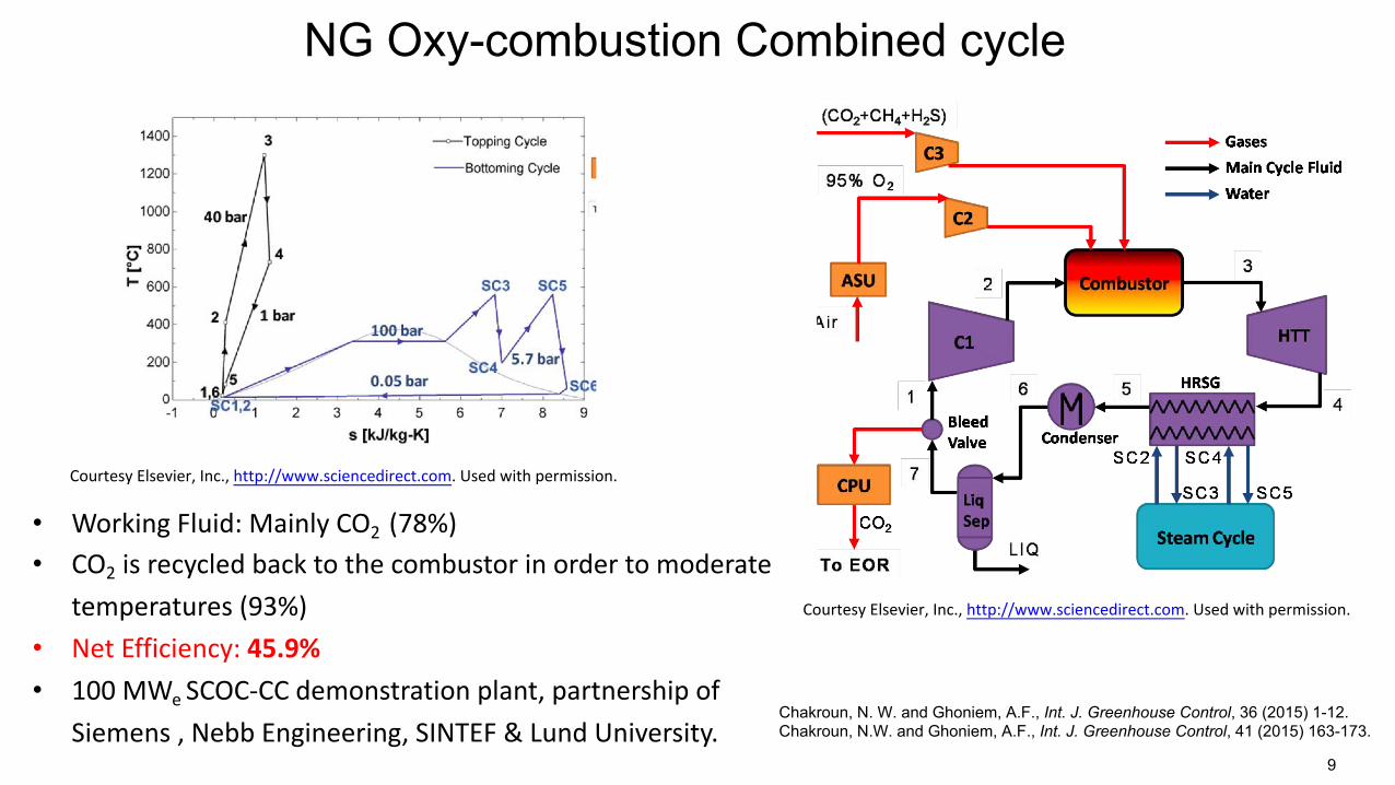
NG Oxy-combustion Combined cycle
• Working Fluid: Mainly CO2 (78%)• CO2 is recycled back to the combustor in order to moderate
temperatures (93%)• Net Efficiency: 45.9%• 100 MWe SCOC-CC demonstration plant, partnership of
Chakroun, N. W. and Ghoniem, A.F., Int. J. Greenhouse Control, 36 (2015) 1-12. Siemens , Nebb Engineering, SINTEF & Lund University. Chakroun, N.W. and Ghoniem, A.F., Int. J. Greenhouse Control, 41 (2015) 163-173.
Courtesy Elsevier, Inc., http://www.sciencedirect.com. Used with permission.
9
Courtesy Elsevier, Inc., http://www.sciencedirect.com. Used with permission.

NG Oxy-Combustion Water cycle
CourtesyElsevier,Inc., http://www.sciencedirect.com.Usedwithpermission.
• Working Fluid: Mainly H2O (94%) • Liquid water is recycled to the combustor to moderate
temperatures (83%) • Net Efficiency: 41.4%
• This cycle has been implemented since 2005 by Clean Energy CourtesyElsevier,Inc., http://www.sciencedirect.com.Usedwithpermission.
Systems (CES) in a 5MW test plant in Kimberlina, CA (world’s first zero emission power plant) 10

Oxygen Penalty SCOCC-CC Water Cycle Graz Cycle
Working Fluid Composition (% vol.)
CO2 87% 6% 10%
H2O 13% 94% 90%
Operating P (bar) 40 100 40
Efficiency Ranges 47-54% 40-49% 48-54%
Cycle Power Breakdown
(% heat input)
Turbine 89.7% 62% 102.7%
Compressors, Pumps
30.8% 2.2% 39%
ASU 8.8% 9.1% 9.2%
CO2 Compression 3% 6.1% 5.9%
Turbine Technologies
Cycle Implementation
• New designs of current gas turbinemachinery needed, due to unusualworking fluid (CO2 &H2O) and high T’s
• Cycle not been implemented in real lifebut layout of cycle is similar to CC’s somodifications may be practical
• A new oxy-fuel power plant w/supercritical CO2 cycle is beingdeveloped by NET Power and a testplant should be completed by 2015
• Steam turbinetechnologies availablefor HPT and LPT, fromCES, for this cycle up tocertain temperatures
• Cycle has been builtand implemented inreal-life by CES at theKimberlina Power Plant
• Needs development ofadvanced turbinetechnology, for HTT, dueto unusual working fluid(H2O & CO2) & high T’s
• Cycle not beenimplemented yet b/c ofcomplexity & unusualworking fluid makes iteconomically unviable(so far) & needs newturbo-machinery design 11

MIEC MEMBRANES (ITM) FOR GAS SEPARATION AND FOR OXY-COMBUSTION
DOE’s cycle, non reactive MSU
ITM: T=700-900˚C
Air
O2-depleted air
High p’O2
Fuel (CH4)
CO2Low p’’O2 +
H2O
./.1 ./.1 %%'& ("#,*+,,- − ("#,',,3
=!"# ',,3 *+,,-4567,&'89, + 4;<=> + 4567,&'89,
• At intermediate T and high ΔpO2, ITMs produces high purity O2 at reduced energy penalty
• Use reactive sweep gas to maintain low p’’O2 and perform air separation and oxy-combustion in same unt
Hong, J., Kirchen, P. and Ghoniem, JMS, 2012, 407, Combust Flame 2013, 160. 12 Kirchen, Hong and Ghoniem, PCI, 2013, 34, 3463.

ITM based ASU (MSRU)/Syngas Production
O2+N2 Depleted-
ABO3-δ
High O2+N2• Large penalty in ASU technology p
• Cryogenic: 0.36 &'ℎ)*⁄+3 ,-. /0
• Small PSA ~ 0.9 &'ℎ)*⁄+3 ,-. /0 P ITM stacks by Air Products
• Ion Transport Membranes (ITM): Diluent low
Diluent+O2
•Oxygen purity: near 100% •/0 separation/reaction combined in a single unit •Energy ~ 0.2 &'ℎ)*⁄+3 ,-. /0 (Fraunhofer IKTS)
In our Labs, we have fabricating some of the best performing pervoskite membranes (LCF, LSCF, BZF, LSCo, LSCrCo, including biphasic and bilayer, novel morphology, etc. for different applications) Fraunhofer Institute, Ba0.5Sr0.5Co0.8Fe0.2O3-δ, uses tubular
membranes, heat recovery to achieve 0.14 kWh/kg_O2
OTM Syngas module by Praxair
Hunt, Dimitrakopoulos,. Ghoniem, J Membrane Science 489 (2015) 248–257. Courtesy Elsevier, Inc., http://www.sciencedirect.com. Used with permission. Hunt, Dimitrakopoulos,. Kirchen, Ghoniem, J Membrane Science 468 (2014) 62–72 13

Chemical Looping for Oxy-combustion
Courtesy Elsevier, Inc., http://www.sciencedirect.com. Used with permission.
14

CHEMICAL LOOPING COMBUSTION USING OXYGEN METAL CARRIERS IN REDOX REACTIONS
AND AN ISOTHERMAL ROTARY REACTOR
Comparison of multi-stage combined cycle designs. The solid circle on the top right-hand corner is for the combined cycle without CCS. CLC-CC with no reheat, 1 or 2 reheat. CLC-CC(r) is the CLC combined cycle with FR flue gas recuperation (no reheat and a single reheat); CLC-CC(s) is the CLC combined cycle with FR flue gas powering a bottom steam cycle. The TIT plays a very important role in determining the efficiency
© ACS Publications. All rights reserved. This content is excluded from our Creative Commons license. For more information, see https://ocw.mit.edu/fairuse.
Zhao, Z.L., Chen, T.J., and Ghoniem, A.F., Energy & Fuels, 2013. 15

PRE-COMBUSTION CO2 CAPTURE, NGCC or IGCC
Carbon or
condenser
air
H R S G
H2 rich gas
C GT
ST
CO2 for storage WG
SR Reformer Gasifier
O2
Hydrocarbon H2O
H2O
CO2 pre-combustion capture. Reformed fuel is shifted and CO2. Estimated efficiency penalty for syngas and NG are 7-13% points and 4-11% points, respectively. Given current efficiencies of coal and NG plants, this amounts to increasing the fuel use by 14-25 % and 16-28 %, respectively.
© Ahmed F. Ghoniem 16

Integrated Gasification Combined Cycle Coal Plants
Air
combustion AGR
Gasifier Types and the exit gas temperature
Fixed Bed Oxygen Nitrogen
ASU 30-60 minutes
Syngas CO+H2 Water GCU Shift
CO2+H2
Coal CO2 H2
slag Fluidized Bed 1-10 minute
Water
Entrained flow
Most common in IGCC
0.1 s
GCU: Gas Cleanup Unit © Source unknown. All rights reserved. This content is excluded from our Creative AGR: Acid Gas Removal to separate CO2 Commons license. For more information, see https://ocw.mit.edu/fairuse.
17

TEMPA ELECTRIC POLK IGCC POWER PLANT
250 MW, 35.3 % efficiency, 2500 TPD coal, 200 TPD sulfuric acid, built 1996, $600M
© Ahmed F. Ghoniem Image courtesy of DOE.
Why add oxygen in gasification ???
steam gasification: C + H2O → CO + H2
is endothermic Δh r = 118 MJ/kgmol C (1)
partial oxidation: C + 1 O2 → CO2
is exothermic Δh r = -123 MJ/kgmol C (2)
Add (1)+(2) makes the gasification nearly autothermal:
2C + 12
O2 + H2O → 2CO + H2
Δh r = -5 MJ/2 kgmol C
⇒ cold gas efficiency: chemical energy in syngas/chemical energy in coal is ~100%
(practical values are lower becasue of heat losses)
18

© Global Carbon Capture and Storage Institute Ltd. All rights reserved. This content is excluded from our Creative Commons license. For more information, see https://ocw.mit.edu/fairuse.
https://www.globalccsinstitute.com/wp-content/uploads/2019/12/GCC_GLOBAL_STATUS_REPORT_2019.pdf
19

�-:° ���
�
� .. �
CaciQp:al Slanp
Uailld&blJ:s
CcdQp:aiSUlnigll
LARGE SCALE CCS FACILITIES IN CONSTRUCTION, ADVANCED AND EARLY DEVELOPMENT
LARGE SCALE CCS FACILITIES IN OPERATION
NO.. TTTlE STAJUS CIOUN'TliY
GOIIGON CAlillllON � Aatnli.a DIOXJDE INJECTION
2 AIM Oll.FIB.D CO.EDR � Clim
3 IUJNOIS INDUSTRIAL CARSON UniledstalmraringCAPTURE Alm SfORAGE dAmaia
4 PETRANOYACMIBOM CAl'TUIIE Uniled!tmsraring dAmaica
5 ABU DHA.BI <X5 �1 BBIIG r.cns Un.iladAnb EMIRATES SJEEL STlilE5} £miala
6 QUEST � caaab IIIJIIClbDII ccclogical
5llcs9 7 untMAMl'tAH CX>.,-EOR �
DEMONSTIIATIION
8 BDUNDMIYDAIII OC:S � C
9 PE11IOllllA5 SANTOS BASINI � Bt:uil PRE.&AU' OIL FIELD ca
10 OOffEY\/U£ � Unil;dSblmGASIFIICAJ'ION Pl.ANT dAmaica
11 AJR PIIOOUCT5 S1EAM UnilldstalmraringMEDMNE lilEFOIIMER dAmaica
12 LOST CABIN GAS PLANT
13 CENT\JIIYPLANT Undid stms r.cns dAmaia
© Global Carbon Capture and Storage Institute Ltd. All rights reserved. This content is excluded from our Creative Commons license. For more information, see https://ocw.mit.edu/fairuse.
OPSIAJ'K)N DATE
INDU5DIY CAPIURE CAPACITY
CAPrURE TYflE
STCIIIACiE TY,PE
pa
..... \I NJllml Pl'oaluilg
tndmtrial ....Clbllll
Dadi:lllacl c�
sam-.
JIO I o.6 lndmtrial [nil.w:,mail
Pl'oaluilg IIIJIIClbllll --...y
....,q ncl Prodlldm
tndmtrial lllplClbllll
Dcdialad Caciap:,al sam-.
JIOl7 l'l:MW ClcZnitiaa
� l'0lt-
apturG
£ah.-.tail
llaaMsy
..... , ..... tndmtrial lllplClbllll
ellh.arcoi l«Dlay
JIO l ln.imtria1 Dadir:Jtocl
l'l:MW Gcanaiaa
..... tndmtrial IIIJIIClbDII l'0lt-omlwtian apturG
[nil.w:,moil«Dlay
[nb.w:,m ail baMsy
Jl<>l!
J,Olj
""''!
r-arlilisu Prodlldicc
�.::nfor l
oilbfning
tndmtrial IIIJIIClbDII tndmtrial lllfDClbllll
tndmtrial llllplClbllll
[nil.w:,mOillaaMsy
[nil.w:,mailllaaMsy
£nb.w:,m0i ll«Dl1sy
JIOlj NJiJln1 Procmliilig
CL') ln.imtrial IIIJIIClbllll
tnbar:«loi a.xo.-ary
..... 0 NJlaDl Pl'oaluilg
.... ln.imtrial IIIJIIClbDII
£ah.-.toil«Dlay
IIIJIIClbDII Caclap:al
NO. TTruE
20 AUIEIIYA CAllllON TIIUU LINE rACn-, Wl1H NOR1H WEST
EDWATER PARTNERSHIP"S SIUIGE'ON REFINERY CO. SlllEAM
21 AUIEIIYA CARSON TRUNK l!INE ��WIJHAGl!IUMOO-.
22 SIMOf'ECQLUPETROCHEMICM. OCS
23 YAMCHAHG IM'TlGIIATED CARSON CAP'TUIE AND STORAGE DEIIDNSTRAnDN
24 WABASHCIO, SEQUESTIUUliOII
25 PORT OF ROTTERDAM CCUS �NEIINl'TlAJl'\IE i,,otlTHOS)
26 NORWAY AJU. C.wtl <X5
71 LAICE CHAlill.E5 METHAIIOL
28 ABU DHABI OCSPHASE 2 • NATUUL GASl'IIOCESSIII&
29 DIIY FOIIK INTE6IIATED COIIIERCIAL CCS
30 CARSONSAFE WNOCS-MACON OClUNTY
31 PROJECT TUNDRA
STATUS Coumrt OPERATIOfl INDUS11IY CAPIURE CAP'TUIE STORAGE DATE CAPACITY TYPE TYPE
pa
Ill Canada )Wu H\d"'91D. I Enhmaicloi CmalJUdicill � � lblclna)'
for oi a.dinilig
Ill canad& .oo.o o.1-o.6 I EJiwiaadoi Ccalnlclico IWdnclion � IIDanu)'
Ill dtlm -.. ...... I Enhmaicloi C<alJU<tJCl1 IWdnclion ll?Jlfflbml lblaJIOay
Ill China UW) •• c,u mical 0-tl £n.lmacloi GcallJUdico IWdnclion � lblaJIOay
Mnamd Ulitacl :.,u rm'lililllr 1.f-lJJ hX1ilolml DGdic:aud dAatma � "')lll3tica c.,qialsam,.
MnDmd Nlthataads l<»l v.aicus 1.0-SJ> \'mlas Dcldicllal c:.qialSmJWl
Mnamcl i,t,rny )W� Olmmt ....,.. v.amus OGlfi:::al..t � �-ad c.,qial!lmJBl
.Mnaaad stala ·'"'4 mi:.al +JIO m.iliiilml £n.lmacl ail d.Aazrica pccliam racu,,uy
Mnamd Uliac!Ar.lb ·""S Nalualpa 41•1.l £n.lmacloi� l«Dlay
...
.Mnaaad stJlla lOlS � � Rlll,.
dA>Mrica axnbustiaa CilplDTII �SlanpOil
l«Dlay
.Mnnaad stala .o� =�n u>-� f\lli.. tlGtiat»d aw dAatma c:aabusliaa
a.xo.-ary mparaiia
Mnaaad dstas l>�•JI026 A:M1ttpzmion µ-� l\:)a. 0Gd!icalDd oawltf,mc .. dAJmrica axnbusliaa14 SH HVlT CO. STORAGE � Narnr -:.a 0,.1 tndmtrial Dodialad
CilplDTII cs Enhaaml Oill«Dlay
CaclQp:al Sloap
15 Glil!EAT PlAJN5 SYNFUEI..S Uniladstaus ,._. tndmtrial Enha;»d ail � � 32 IJIIEGRATED MID-CONTINENT Mnamd dst-. i;th.m,l t.,p v:mcusPLANT MID WFtBlaN.MIDN..E dAmuia N-.itcu lo�-JIU�flllplClbDII ll«Dl1sy STACKED CAllllON STORAGE dewq,au, .. «Aal.cr:a puflKiiaa.16 SLBPMEROO. STORAGE � N11n11� Dodiclllacl HUB �.:at.a
� "'PClbllll Caciap:,al
33 CAJilllONNET Adnoaad Auslr:W lOllO"l takrCYll!DJa � UlldRr f7 SHUTE CREEK� raring Uailldstaus 1� Nllla:Jlcu ; ln.imwl £nh.aladoi �
PROCESSING PUNT dAmaica llllplClbllll ll«IMlyProalssillg 34 OXY Alm WHITl: ENEIIGY .. u.11 � ln.imwl i:rui-»d oi l«DlayElHANOI. EOR FillC&J'TY � mp:araiao18 ENID FeilTUSEII
dAmaica
l r<Zrtiii,u I Cnh.am,d ail llaaMsy0,.1
laJDClbllll •°"
Produ<Da1 35 SINOf'EC EASJERN Eady ctiaa ln.imwl i:rui-»d oil O.S(IC OC519 TERREU NATURAL GAS � u· staus l 72 Nm:n1 ....... •<Lf £nhz:iaid Oi
PROCESSING PUKT tf'OaERlY dAmnia Pl'0cluilg aapu:aliaa ll«Dl1syVA!. \/BIDE NATURAL 6AS PUNTS) HYDlilOGBC 2 MIIGNUM (HUC) Ddy A:lwcrCmmilbm Dadir:Jtocl36 lU.l.+ 1.uu
dndl:fau, .. 20

© Global Carbon Capture and Storage Institute Ltd. All rights reserved. This content is excluded from our Creative Commons license. For more information, see https://ocw.mit.edu/fairuse.
https://www.globalccsinstitute.com/wp-content/uploads/2019/12/GCC_GLOBAL_STATUS_REPORT_2019.pdf Oil recovery is under:
Field pressure (primary): 15% Water floods (secondary): 30 %
© Ahmed F. Ghoniem CO2 flood (tertiary): 15% 21
Chemical scrubbing of CO2 from flue gases has already been demonstrated.
During 82-86, an aqueous solution of MEA was used in: Lubbock Power plant, Texas, NG was fired in a 50 MW plant, producing near 1000 t/d of CO2 , and in a coal-steam generator in Carlsbad NM producing 113 t/d. In both cases, CO2 was used for enhanced oil recovery (EOR) in nearby fields.
1991, CO2 scrubbing using 15-20% MEA solutions in the 300 MW Shady Point Combined Heat and Power Plant in Oklahoma has been producing nearly 400 t/d CO2, which is used in the food industry and in EOR.
A similar operation is done in a Botswana plant burning coal.
Norway Sleipner Vest gas field separates CO2 from the recovered natural gas to reduce CO2 concentration in the produced gas from 95% to 2.5%. The separated CO2 is then injected back into a 250 m deep aquifer located 800 m below the ocean surface.
© Ahmed F. Ghoniem 22

MIT OpenCourseWare https://ocw.mit.edu/
2.60J Fundamentals of Advanced Energy Conversion Spring 2020
For information about citing these materials or our Terms of Use, visit: https://ocw.mit.edu/terms.