CNC Mill/VMC Controller User Manualcnc4pc.com/Tech_Docs/03 - User Manual, Doc V1.5 - Mill...
35
Hind Technology Group Document Ownership Hind Technology Group Last document update 29 September 2015 © Copyright Hind Technology Group All rights reserved. Reproduction in whole or in parts is prohibited without the written consent of the copyright owner. For any questions or remarks on this document, please contact Hind Technology Group. Page 1 of 35 Document Version 1.5 v2 CNC Mill/VMC Controller User Manual v2
Transcript of CNC Mill/VMC Controller User Manualcnc4pc.com/Tech_Docs/03 - User Manual, Doc V1.5 - Mill...
Hind Technology Group
Document Ownership Hind Technology Group
Last document update 29 September 2015 © Copyright Hind Technology Group
All rights reserved. Reproduction in whole or in parts is prohibited without the written consent of the copyright owner. For any questions or remarks on this document, please contact Hind Technology Group.
Page 1 of 35Document Version 1.5v2
CNC Mill/VMC Controller
User Manual
v2
Hind Technology Group
Table of Contents
1 Introduction _____________________________________________________________________ 41.1 Overview ____________________________________________________________________ 41.2 Warnings and Caution Information ________________________________________________ 41.3 Software features _____________________________________________________________ 51.4 Hardware features ____________________________________________________________ 5
2 System Overview _________________________________________________________________ 62.1 Overview ____________________________________________________________________ 62.2 System Layout ________________________________________________________________ 6
2.2.1 Controller Layout _________________________________________________________ 62.2.2 User Interface Layout ______________________________________________________ 72.2.3 Keyboard Controls _________________________________________________________ 7
2.3 Power Procedures _____________________________________________________________ 82.3.1 Power On Precautions _____________________________________________________ 82.3.2 Power OFF Precautions _____________________________________________________ 8
2.4 Control Conditions for Powering On _______________________________________________ 82.5 Emergency Stop (E-Stop) operations ______________________________________________ 9
3 Graphical Interface _______________________________________________________________ 103.1 F1 – Help and Setup Screen ____________________________________________________ 103.2 F2 – Program Screen __________________________________________________________ 113.3 F3 – Jog/Rapid Screen _________________________________________________________ 123.4 F4 – Tools Table Screen ________________________________________________________ 123.5 F5 – Recent Files Screen _______________________________________________________ 133.6 F6 – Load Files Screen _________________________________________________________ 13
4 Setting up the system _____________________________________________________________ 144.1 Default system password ______________________________________________________ 144.2 Setting System Time __________________________________________________________ 14
5 Manual & MDI Operations _________________________________________________________ 155.1 Homing ____________________________________________________________________ 155.2 Rapid / Jog __________________________________________________________________ 165.3 MDI Operations ______________________________________________________________ 175.4 Using MPG (Manual Pulse Generator) ____________________________________________ 17
6 G-Code Operations _______________________________________________________________ 186.1 Creating New G-Code Files _____________________________________________________ 186.2 Editing G-Code ______________________________________________________________ 186.3 Supported G-Codes ___________________________________________________________ 196.4 Supported M-Codes __________________________________________________________ 20
Page 2 of 35Document Version 1.5v2

Hind Technology Group
7 Loading & Running G-code Programs ________________________________________________ 217.1 Loading Files from SD Card _____________________________________________________ 21
7.1.1 Load File Menu __________________________________________________________ 217.1.2 Recent Files Menu _______________________________________________________ 21
7.2 Running G-code programs _____________________________________________________ 217.3 Stopping Program (Feed Hold) __________________________________________________ 217.4 Resuming Program ___________________________________________________________ 217.5 Restarting Program from Start __________________________________________________ 21
8 Managing Tools __________________________________________________________________ 22
9 Managing Work Offsets ___________________________________________________________ 23
10 Hardware Connections ___________________________________________________________ 2410.1 Power Connector ___________________________________________________________ 2410.2 VGA Connector _____________________________________________________________ 2510.3 USB Connector _____________________________________________________________ 2510.4 Servo/Stepper Motor Connectors for X, Y & Z Axis _________________________________ 2510.5 Coolant and Lubrication Connector _____________________________________________ 2610.6 Tower Light Connector _______________________________________________________ 2710.7 E-Stop and Guard Door Connector ______________________________________________ 2810.8 Analog Inputs ______________________________________________________________ 2910.9 RS 232 Connector ___________________________________________________________ 2910.10 Auxiliary Input / Fly by wire __________________________________________________ 2910.11 Auxiliary Outputs __________________________________________________________ 3010.12 Spindle Connector __________________________________________________________ 3010.13 Spindle RPM Sensor ________________________________________________________ 3110.14 Home Input _______________________________________________________________ 31
11 Upgrading/Unlocking the controller ________________________________________________ 32
12 Detailed Specifications ___________________________________________________________ 3312.1 Electrical __________________________________________________________________ 3312.2 Mechanical data ____________________________________________________________ 33
13 Getting Support ________________________________________________________________ 3413.1.1 Reporting Bugs _________________________________________________________ 34
14 Warranty ______________________________________________________________________ 35
Page 3 of 35Document Version 1.5v2

Hind Technology Group
1 Introduction
1.1 Overview
Computer Numerical Control (CNC) is one in which the functions and motions of a machine tool are controlledby means of a prepared program containing coded alphanumeric data. CNC can control the motions of thework piece or tool, the input parameters such as feed, depth of cut, speed and functions such as turningspindle on/off, turning coolant on/off.
HTG CNC Controller link to CNC Controller to motor drivers supporting step/direction control. They arecompatible with most of drives to control motion of motors. HTG CNC Controller uses USB port to take inputfrom keyboard and a VGA output to display on screen.
HTG controller provides complete Hardware/Software Solution. Additional machine control is not required.The HTG CNC Controller is a dedicated application, designed to fully exploit the features of the purpose-builthardware. It has many advanced features to assist day-to-day CNC machine operation.
1.2 Warnings and Caution Information
WARNING: Indicates circumstances or practices that can lead to personal injury as well as to damage to the control, the machine, or other equipment.
CAUTION: Indicates circumstances or practices that can lead to damage to the control or other equipment.
1 Introduction
Page 4 of 35Document Version 1.5v2

Hind Technology Group
1.3 Software features
• Machine and job status visualisation in real-time
• Easy user interface
• Keyboard rapid and jogging
1.4 Hardware features
• Repetitive Job Feature
• USB Keyboard Support
• VGA interface for standard LCD screens
• Dedicated system requiring no PC interface
• SD Card support for loading G-code
• Program Start, Stop and Resume functionality
• Can be interfaced to standard Servo/Stepper drives and motors
• RS-232 pot for expandability
• Isolated inputs
• Systems health and power monitoring system
• Fly by Wire/Dual MPG pendant support
• Output for flood, Mist and Lubrication
• Light tower control
• 5 isolated auxiliary inputs
• 5 auxiliary outputs
• 2 Analog inputs
• Standard MPG dial support
1 Introduction
Page 5 of 35Document Version 1.5v2

Hind Technology Group
2 System Overview
2.1 Overview
This chapter describes how to operate the HTG CNC Controllers.
2.2 System Layout
2.2.1 Controller Layout
2 System O
verview
Page 6 of 35Document Version 1.5v2
SD Card Slot
USB KeyboardConnector LCD VGA
ConnectorPower
Connector
ControllerIdentification Label
Green ConnectorsFor I/O
Hind Technology Group
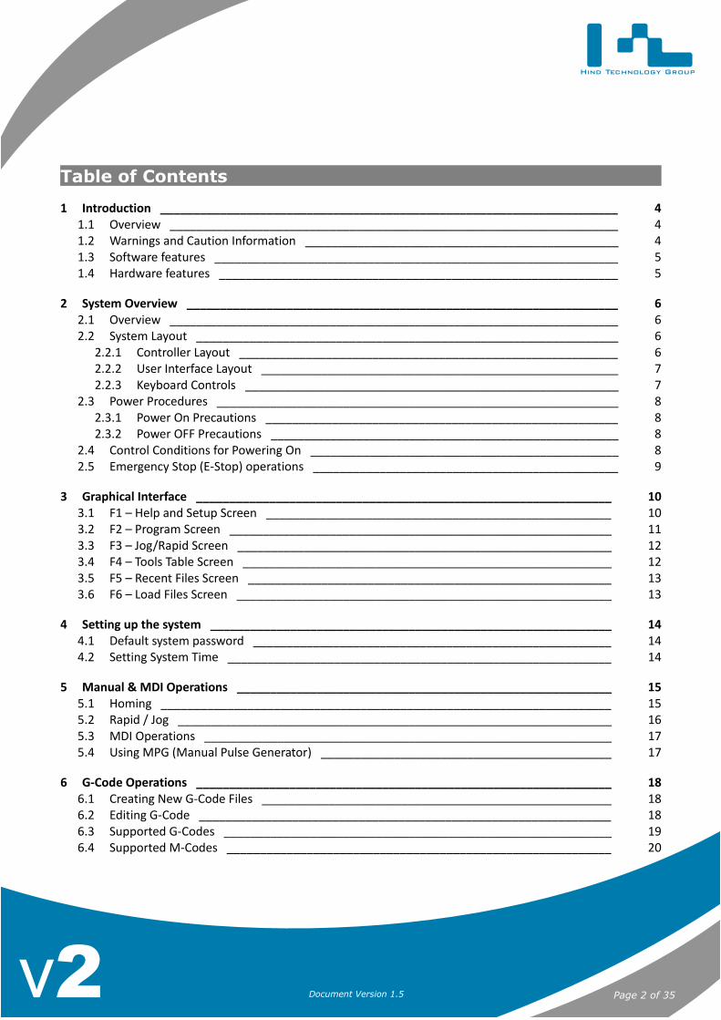
2.2.2 User Interface Layout
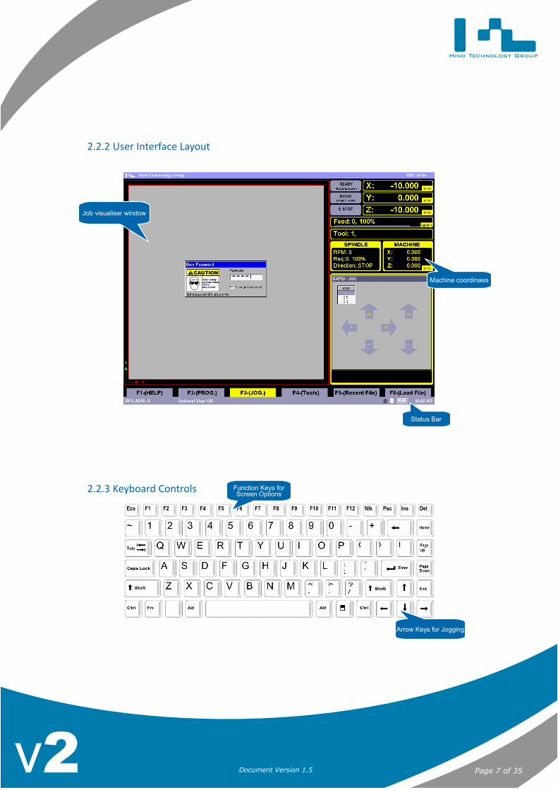
2.2.3 Keyboard Controls
2 System O
verview
Page 7 of 35Document Version 1.5v2
Job visualiser window
Status Bar
Machine coordinaes
Arrow Keys for Jogging
Function Keys forScreen Options
Hind Technology Group
2.3 Power Procedures
2.3.1 Power On Precautions
1. Visually check to make sure that the control and the machine are in normal operating conditions.2. Power ON the machine.3. If characters are not displayed on the screen within 30 seconds, press4. the power OFF button immediately.
2.3.2 Power OFF Precautions
1. Before you turn the power off, make sure that the control is in STOP.2. Press the E-Stop button.3. Make sure that power is turned off to all peripheral devices (tape reader, tape punch, etc.) that are
connected to the control.4. Press the power OFF button.
WARNING: To prevent damage to the machine, never turn off power while a part program is being executed.Before turning off power, make sure that the control is in STOP.
2.4 Control Conditions for Powering On
After powering up the system, the system resets a number of initial operating conditions as listed below:
• The system is placed in E-Stop. The system is not allowed to come out of E-Stop and the user is alertedto reset E-Stop and then home the machine before being able to use the machine.
• The system defaults to the following after power up:
◦ Default plane selection
◦ Default machine units, mm or inches
◦ Coordinate system is reset to absolute
◦ Job offsets are reset
◦ Default feed rate
2 System O
verview
Page 8 of 35Document Version 1.5v2

Hind Technology Group
2.5 Emergency Stop (E-Stop) operations
To use this feature Press the red E-Stop button or any other E-Stop switches installed on the machine to stop operationsregardless of the condition of the control and the machine.
Pressing the E-Stop Button will result in the following:
• E-Stop Button will start blink on screen alerting that E-Stop is activated.
• The machine tower light and controller “Error” LED light on the front panel will start blinking indicatingthat the control has gone into lock state.
• All axis motors are disabled immediately.
• Spindle is put in brake position through VFD.
Note: If E-Stop button is pressed while a part program is running, program execution will halt and the machine can onlybe used after a fulling homing cycle.
Emergency Stop Reset:
• Before resetting the emergency stop state, first locate and eliminate the cause of the emergency stop.
• If the E-Stop button is locked in the pressed position, it must be released before the emergency stop state canbe reset.
• Next the user can use the Rapid/Jog features to move the machine axis.
• Once its safe to home the machine, press CTRL + ATL + HOME to home the machine.
• NOTE: The machine can only be used after a fulling homing cycle.
2 System O
verview
Page 9 of 35Document Version 1.5v2
Hind Technology Group
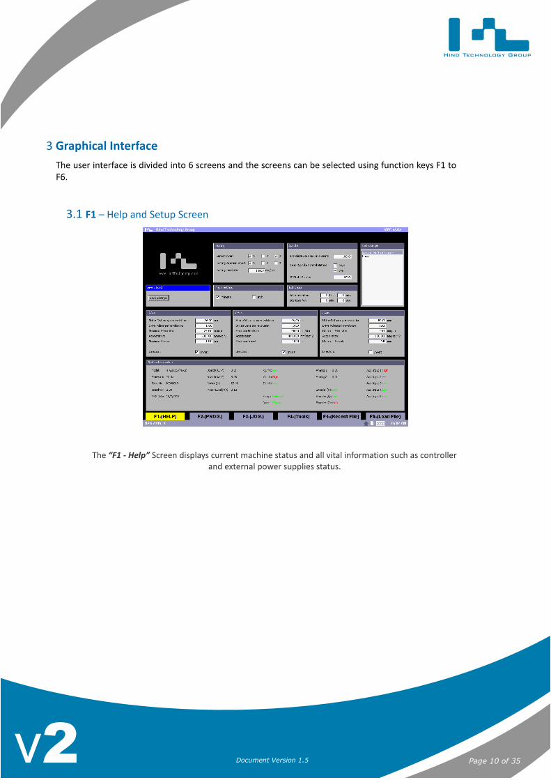
3 Graphical InterfaceThe user interface is divided into 6 screens and the screens can be selected using function keys F1 toF6.
3.1 F1 – Help and Setup Screen
The “F1 - Help” Screen displays current machine status and all vital information such as controllerand external power supplies status.
3 Graphical Interface
Page 10 of 35Document Version 1.5v2
Hind Technology Group
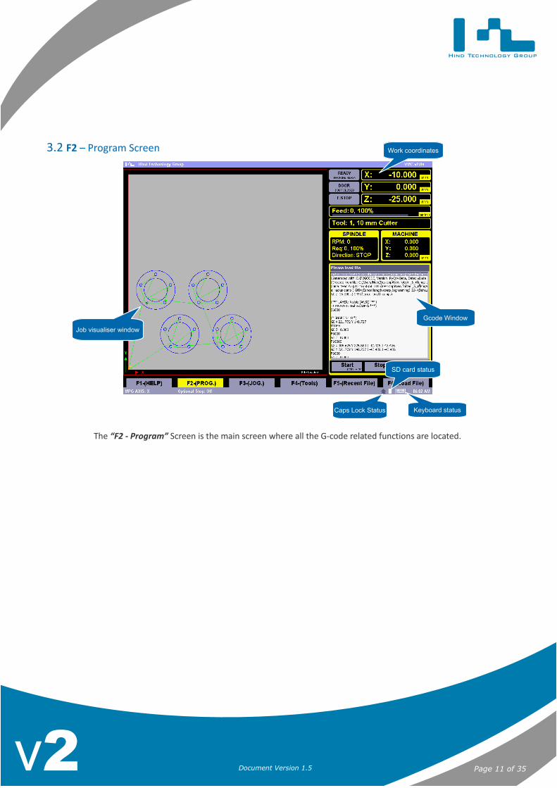
3.2 F2 – Program Screen
The “F2 - Program” Screen is the main screen where all the G-code related functions are located.
3 Graphical Interface
Page 11 of 35Document Version 1.5v2
Gcode Window
Keyboard status
SD card status
Job visualiser window
Work coordinates
Caps Lock Status
Hind Technology Group
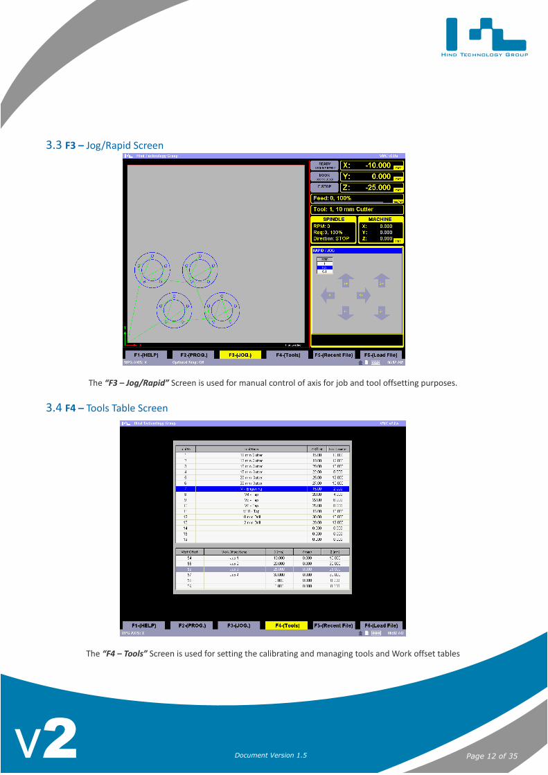
3.3 F3 – Jog/Rapid Screen
The “F3 – Jog/Rapid” Screen is used for manual control of axis for job and tool offsetting purposes.
3.4 F4 – Tools Table Screen
The “F4 – Tools” Screen is used for setting the calibrating and managing tools and Work offset tables
3 Graphical Interface
Page 12 of 35Document Version 1.5v2
Hind Technology Group
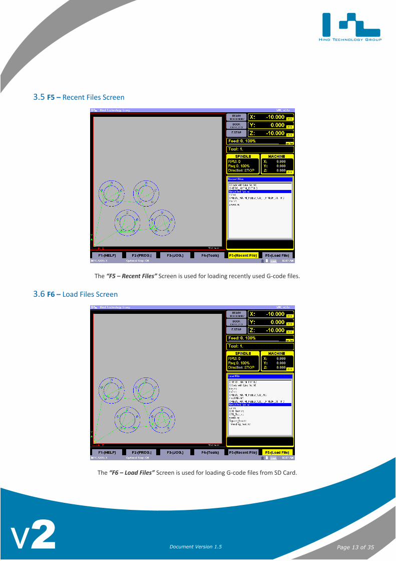
3.5 F5 – Recent Files Screen
The “F5 – Recent Files” Screen is used for loading recently used G-code files.
3.6 F6 – Load Files Screen
The “F6 – Load Files” Screen is used for loading G-code files from SD Card.
3 Graphical Interface
Page 13 of 35Document Version 1.5v2
Hind Technology Group
4 Setting up the system
4.1 Default system password
By default the system password is set to HTG in capital letters for both Admin and User logins.
4.2 Setting System Time
• Press “F2” to goto the “F2 - Program” screen
• Next press CTRL + M to open the MDI Window
• For example to set system time to 10:30 AM, type Time:10:30 and press the Enter key
• NOTE: The time must be entered in 24 hour format and no spaces between characters
Page 14 of 35Document Version 1.5v2

Hind Technology Group
5 Manual & MDI Operations
5.1 Homing
5 Manual &
MD
I Operations
Page 15 of 35Document Version 1.5v2
Press “CTRL+ALT+HOME” to home the machine
Homing Status
The system is not homed, press CTRL + ALT + HOME to start the homing sequence
Machine is homing, please wait while homing finishes. Press Escape key to abort homing
System homed successfully and machine ready
Homing error, this might be caused due to bad homing switches or cables
Hind Technology Group
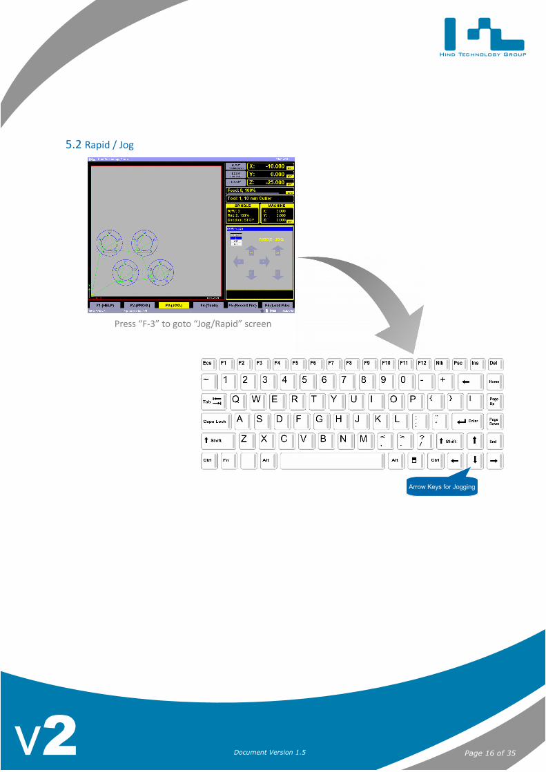
5.2 Rapid / Jog
5 Manual &
MD
I Operations
Page 16 of 35Document Version 1.5v2
Press “F-3” to goto “Jog/Rapid” screen
Arrow Keys for Jogging
Hind Technology Group
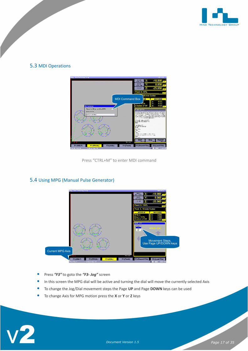
5.3 MDI Operations
5.4 Using MPG (Manual Pulse Generator)
• Press “F3” to goto the “F3- Jog” screen
• In this screen the MPG dial will be active and turning the dial will move the currently selected Axis
• To change the Jog/Dial movement steps the Page UP and Page DOWN keys can be used
• To change Axis for MPG motion press the X or Y or Z keys
5 Manual &
MD
I Operations
Page 17 of 35Document Version 1.5v2
Press “CTRL+M” to enter MDI command
MDI Command Box
Current MPG Axis
Movement Steps,Use Page UP/DOWN keys

Hind Technology Group
6 G-Code Operations
6.1 Creating New G-Code Files
• Press “F2” to goto the “F2 - Program” screen
• Next press CTRL + N to open a new file name window
• Enter the file name and press the ENTER key to open the file edit window
6.2 Editing G-Code
• Press “F2” to goto the “F2 - Program” screen
• Next press CTRL + E to open the edit file window
6 G-Code O
perations
Page 18 of 35Document Version 1.5v2
Hind Technology Group
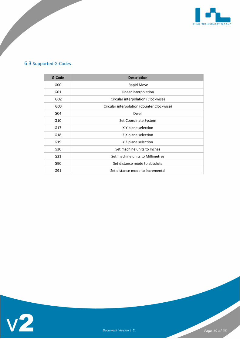
6.3 Supported G-Codes
G-Code Description
G00 Rapid Move
G01 Linear interpolation
G02 Circular interpolation (Clockwise)
G03 Circular interpolation (Counter Clockwise)
G04 Dwell
G10 Set Coordinate System
G17 X Y plane selection
G18 Z X plane selection
G19 Y Z plane selection
G20 Set machine units to Inches
G21 Set machine units to Millimetres
G90 Set distance mode to absolute
G91 Set distance mode to incremental
6 G-Code O
perations
Page 19 of 35Document Version 1.5v2
Hind Technology Group
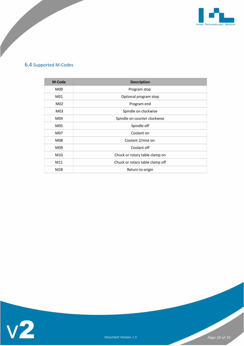
6.4 Supported M-Codes
M-Code Description
M00 Program stop
M01 Optional program stop
M02 Program end
M03 Spindle on clockwise
M04 Spindle on counter clockwise
M05 Spindle off
M07 Coolant on
M08 Coolant 2/mist on
M09 Coolant off
M10 Chuck or rotary table clamp on
M11 Chuck or rotary table clamp off
M28 Return to origin
6 G-Code O
perations
Page 20 of 35Document Version 1.5v2

Hind Technology Group
7 Loading & Running G-code Programs
7.1 Loading Files from SD Card
7.1.1 Load File Menu
1. Press “F6” to goto the “F6 - Load File” screen.2. Next from the list of files displayed, using the UP and DOWN arrow keys select the file.3. Press ENTER and the file preview will be displayed in the visualiser window.4. Pressing enter again will load the file for machining and the screen will automatically change to “F2 -
Program”.
7.1.2 Recent Files Menu
1. Press “F5” to goto the “F5 - Recent File” screen.2. Next from the list of files displayed, using the UP and DOWN arrow keys select the file.3. Press ENTER and the file preview will be displayed in the visualiser window.1. Pressing enter again will load the file for machining and the screen will automatically change to “F2 -
Program”.
7.2 Running G-code programs
1. Programs can only be run from the “F2 – Program” screen, Press “F2” to goto the “F2 - Program” screenif already not in the “F2 – Program” screen.
2. Press “CTRL + S” to start the program.
7.3 Stopping Program (Feed Hold)
1. Pressing the “Escape Key” will stop the program and put the system in Feed Hold mode.
7.4 Resuming Program
1. Programs can only be resumed from the “F2 – Program” screen, Press “F2” to goto the “F2 - Program” screen if already not in the “F2 – Program” screen.
1. Press “CTRL + S” to start the program.
7.5 Restarting Program from Start
1. If you require to restart the Program from staring, Press “CTRL + R”.2. Press “CTRL + S” to start the program.
7 Loading & Running G
-code Programs
Page 21 of 35Document Version 1.5v2
Hind Technology Group
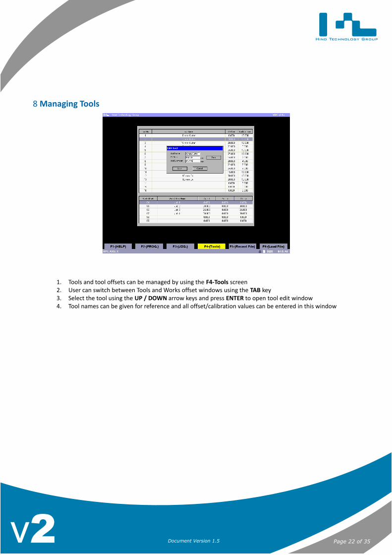
8 Managing Tools
1. Tools and tool offsets can be managed by using the F4-Tools screen2. User can switch between Tools and Works offset windows using the TAB key3. Select the tool using the UP / DOWN arrow keys and press ENTER to open tool edit window4. Tool names can be given for reference and all offset/calibration values can be entered in this window
8 Managing Tools
Page 22 of 35Document Version 1.5v2

Hind Technology Group
9 Managing Work Offsets
1. Work offsets can be managed by using the F4-Tools screen2. User can switch between Tools and Works offset windows using the TAB key3. Select the Work offset using the UP / DOWN arrow keys and press ENTER to open work offset edit window4. Work offset names can be given for reference and all offset values can be entered in this window
9 Managing W
ork Offsets
Page 23 of 35Document Version 1.5v2
Hind Technology Group
Spindle ControlConnector
Tower LightConnector
Collant, Mist &Lubrication Outputs
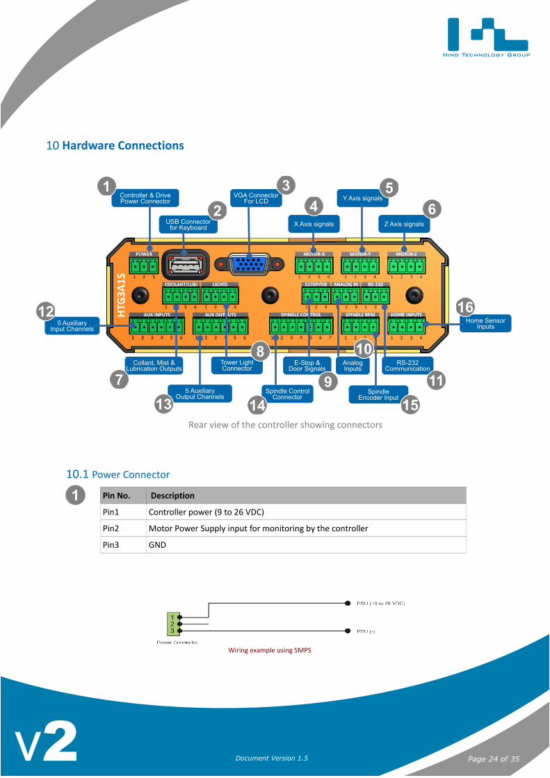
10 Hardware Connections
10.1 Power Connector
Pin No. Description
Pin1 Controller power (9 to 26 VDC)
Pin2 Motor Power Supply input for monitoring by the controller
Pin3 GND
10 Hardw
are Connections
Page 24 of 35Document Version 1.5v2
VGA ConnectorFor LCD
Controller & DrivePower Connector Y Axis signals
Z Axis signalsUSB Connectorfor Keyboard X Axis signals
SpindleEncoder Input
5 AuxiliaryOutput Channels
E-Stop &Door Signals
AnalogInputs
RS-232Communication
Home SensorInputs5 Auxiliary
Input Channels
12
11
10
9
8
16
151413
7
Rear view of the controller showing connectors
1
Wiring example using SMPS
1
2
3
45
6

Hind Technology Group
10.2 VGA Connector
A standard 15 pin female VGA connector is used to connect to an external LCD monitor.
10.3 USB Connector
Standard USB connector for connecting a USB keyboard/Numpad to the system.
10.4 Servo/Stepper Motor Connectors for X, Y & Z Axis
Pin No. Description Type
Pin1 X – Pulse(+) Differential Signal (-5 to +5v)
Pin2 X – Pulse(-) Differential Signal (-5 to +5v)
Pin3 X – Direction(+) Differential Signal (-5 to +5v)
Pin4 X – Direction(-) Differential Signal (-5 to +5v)
Pin No. Description Type
Pin1 Y – Pulse(+) Differential Signal (-5 to +5v)
Pin2 Y – Pulse(-) Differential Signal (-5 to +5v)
Pin3 Y – Direction(+) Differential Signal (-5 to +5v)
Pin4 Y – Direction(-) Differential Signal (-5 to +5v)
Pin No. Description Type
Pin1 Z – Pulse(+) Differential Signal (-5 to +5v)
Pin2 Z – Pulse(-) Differential Signal (-5 to +5v)
Pin3 Z – Direction(+) Differential Signal (-5 to +5v)
Pin4 Z – Direction(-) Differential Signal (-5 to +5v)
10 Hardw
are Connections
Page 25 of 35Document Version 1.5v2
2
3
4
5
6
Wiring example using FUJI make Alpha 5 Drive

Hind Technology Group
10.5 Coolant and Lubrication Connector
Pin No. Description Type
Pin1 Flood Coolant Power Signal
Pin2 Mist Coolant Power Signal
Pin3 Lubrication Power Signal
Pin4 +ve power that is connected to the controller Common +ve
10 Hardw
are Connections
Page 26 of 35Document Version 1.5v2
7
Wiring example using 24VDC SMPS and 24VDC Relays for Plasma ARC On/Off and Lubrication Pump On/Off

Hind Technology Group
10.6 Tower Light Connector
Pin No. Description
Pin1 Light Signal 1
Pin2 Light Signal 2
Pin3 Light Signal 3
Pin4 +ve power that is connected to the controller
10 Hardw
are Connections
Page 27 of 35Document Version 1.5v2
8
Wiring example using 24VDC SMPS and 24VDC Tower Lights
Hind Technology Group
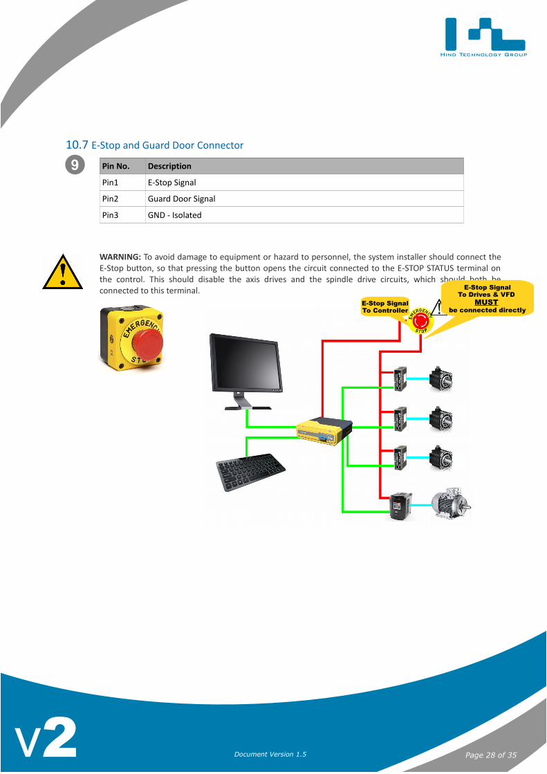
10.7 E-Stop and Guard Door Connector
Pin No. Description
Pin1 E-Stop Signal
Pin2 Guard Door Signal
Pin3 GND - Isolated
WARNING: To avoid damage to equipment or hazard to personnel, the system installer should connect theE-Stop button, so that pressing the button opens the circuit connected to the E-STOP STATUS terminal onthe control. This should disable the axis drives and the spindle drive circuits, which should both beconnected to this terminal.
10 Hardw
are Connections
Page 28 of 35Document Version 1.5v2
9
E-Stop SignalTo Controller
E-Stop SignalTo Drives & VFD
MUST be connected directly
Hind Technology Group
10.8 Analog Inputs
Pin No. Description Type
Pin1 Analog Input 1 0 to 5 Volts
Pin2 Analog Input 2 0 to 5 Volts
Pin3 GND
10.9 RS 232 Connector
Pin No. Description Type
Pin1 RS-232 RXD -12v to +12v
Pin2 RS-232 TXD -12v to +12v
Pin3 Negative from Switch/Sensor - Isolated Negative
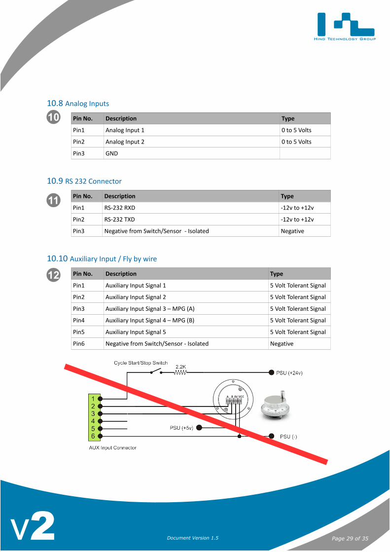
10.10 Auxiliary Input / Fly by wire
Pin No. Description Type
Pin1 Auxiliary Input Signal 1 5 Volt Tolerant Signal
Pin2 Auxiliary Input Signal 2 5 Volt Tolerant Signal
Pin3 Auxiliary Input Signal 3 – MPG (A) 5 Volt Tolerant Signal
Pin4 Auxiliary Input Signal 4 – MPG (B) 5 Volt Tolerant Signal
Pin5 Auxiliary Input Signal 5 5 Volt Tolerant Signal
Pin6 Negative from Switch/Sensor - Isolated Negative
10 Hardw
are Connections
Page 29 of 35Document Version 1.5v2
10
11
12
Hind Technology Group
10.11 Auxiliary Outputs
Pin No. Description Type
Pin1 Output Signal - Chuck or rotary table clamp TTL 5 Volt
Pin2 Output Signal TTL 5 Volt
Pin3 Output Signal TTL 5 Volt
Pin4 Output Signal TTL 5 Volt
Pin5 Output Signal TTL 5 Volt
Pin6 GND
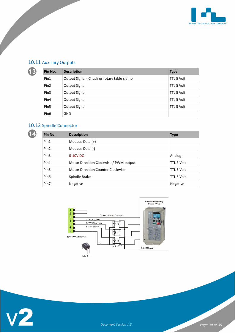
10.12 Spindle Connector
Pin No. Description Type
Pin1 Modbus Data (+)
Pin2 Modbus Data (-)
Pin3 0-10V DC Analog
Pin4 Motor Direction Clockwise / PWM output TTL 5 Volt
Pin5 Motor Direction Counter Clockwise TTL 5 Volt
Pin6 Spindle Brake TTL 5 Volt
Pin7 Negative Negative
10 Hardw
are Connections
Page 30 of 35Document Version 1.5v2
13
14
Hind Technology Group
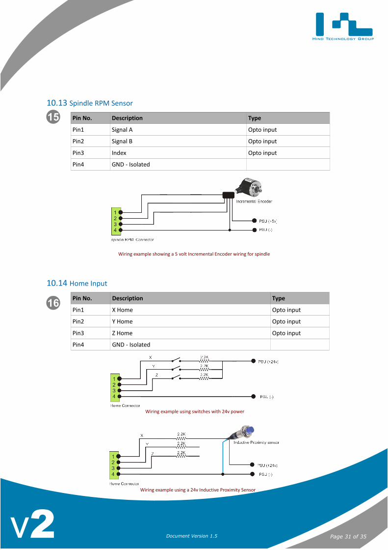
10.13 Spindle RPM Sensor
Pin No. Description Type
Pin1 Signal A Opto input
Pin2 Signal B Opto input
Pin3 Index Opto input
Pin4 GND - Isolated
10.14 Home Input
Pin No. Description Type
Pin1 X Home Opto input
Pin2 Y Home Opto input
Pin3 Z Home Opto input
Pin4 GND - Isolated
10 Hardw
are Connections
Page 31 of 35Document Version 1.5v2
15
16
Wiring example using switches with 24v power
Wiring example showing a 5 volt Incremental Encoder wiring for spindle
Wiring example using a 24v Inductive Proximity Sensor

Hind Technology Group
11 Upgrading/Unlocking the controllerRegular updates are released to add more features to the units. Custom software's are also released for special clientrequirements. The software up-gradation process can be easily performed on site by following the instructions below:
• Check that the “Controller-xxxxxxxx.htg” file matches the serial number of the controller.
• Copy the “Controller-xxxxxxxx.htg” file to a SD card
• Power off the controller
• Insert the SD card into the controller
• Power up the controller and a message will be displayed on the screen showing the upgrade status
• Once the upgrade is finished please remove the SD Card and power cycle the unit
11 Upgrading/U
nlocking the controller
Page 32 of 35Document Version 1.5v2

Hind Technology Group
12 Detailed Specifications
12.1 Electrical
• Input voltage: 9 - 26 VDC.
12.2 Mechanical data
12 Detailed Specifications
Page 33 of 35Document Version 1.5v2
Hind Technology Group
13 Getting SupportFull support for our products is available and the users/clients can directly get in touch with our support staff by visitingwww.hindtechnology.com or by emailing SUPPORT at [email protected]
13.1.1 Reporting Bugs
If during operations the system behaves unexpected or any bugs are found then the user should email SUPPORTthe following information so that we can have the issue resolved at the earliest:
1. Take a screenshot of the current screen by pressing the “Ctrl+Alt+Ptr Sc” keys on the keyboard. Amessage will be displayed on the screen notifying the user that the file has been saved to the SD Card.
2. Next email the above generated file to SUPPORT and a detailed description of the issue.3. If the issue is related to a particular G-code then email the G-code file so that we can replicate the
problem at our end.
13 Getting Support
Page 34 of 35Document Version 1.5v2

Hind Technology Group
14 WarrantyAll units are warranted to be free from defects in workmanship and material, and are warranted to meet the Company'spublished specifications, but no other warranty, expressed or implied, is made by the seller unless expressly set forth.Hind Technology Group warrants its equipment for two (2) years to be free from defects in workmanship and material.
Hind Technology Group shall have no obligation or liability under this warranty:
• For special, indirect or consequential personal or property damage arising from the failure of its equipment.
• If the equipment was not installed, operated or maintained in accordance to Hind Technology Group's installationinstructions.
• If the equipment was serviced, repaired, altered or modified in any way by a third party other than HindTechnology Group authorised personnel.
Hind Technology Group further reserves the right to the following:
• The right to repair or replace customers' units at its discretion.
• The right under this warranty to refuse or reject any and all warranty claims for any reason whatsoever if, basedon the Company's estimation, damage to subject equipment was not caused by component or factoryworkmanship defects.
Any unit sent back to Hind Technology Group for warranty repair must have prior notification and approval for the returnor the unit will be refused delivery.
All transportation costs, both in-bound and out-bound freight, are the responsibility of the customer.
14 Warranty
Page 35 of 35Document Version 1.5v2