CMC ( CONTROLLED MODULUS COLUMNS ) : POTENTIAL …
8
57ième CONGRÈS CANADIEN DE GÉOTECHNIQUE 57TH CANADIAN GEOTECHNICAL CONFERENCE 5ième CONGRÈS CONJOINT SCG/AIH-CNN 5TH JOINT CGS/IAH-CNC CONFERENCE CMC ( CONTROLLED MODULUS COLUMNS ) : POTENTIAL APPLICATION TO CANADIAN SOILS WITH A NEW TREND IN GROUND IMPROVEMENT Frederic Masse, DGI-Menard, Inc., Bridgevile, PA, USA Bill Brockbank, RECO Canada, Toronto Seth Pearlman, P.E., DGI-Menard, Inc., Bridgeville, PA, USA ABSTRACT Controlled Modulus Columns ( CMC ) were developed in Europe to meet technical, financial & quality requirements of a constantly more demanding ground improvement market. Classical ground improvement technologies such as Dynamic Compaction, Wick Drains and Stone Columns were frequently pushed to their limits by more and more stringent settlement and bearing capacity criteria and challenging environments. The need of improved quality, tighter schedule and at the same time restricted budget led to the development of ground improvement solutions that were requiring design refinements and increased equipment productivity never experienced before in ground improvement. CMC are one of these new technologies. They are a vertical semi-rigid inclusion system that is designed to obtain a composite material ( soil + inclusions ). The CMC process has been subject to intense research programs in France in conjunction with Bureau Veritas in order to define a design manual, design codes and a construction procedure. CMC are created using a lean sand-mix or very fluid mortar injected through a hollow stem displacement auger with low pressure in a continuous way during extraction creating a semi-rigid column. This paper will present details on the installation method, equipment, design philosophy as well as several case studies with examples of FEM analysis. The potential of CMC in Canada will also be discussed RÉSUMÉ Les Colonnes a Module Contrôle ont ete développees en Europe afin de répondre a des demandes croissantes techniques, financières et de qualité d’un marche de l’amélioration de sols de plus en plus exigeant et compétitif. Les techniques d’amélioration de sols classiques telles que le Compactage Dynamique, les Drains Verticaux ou les Colonnes Ballastées étaient de façon fréquente poussées dans leur retranchement par des critères de tassement et de portance de plus en plus exigeants et par des environnements de plus en plus difficiles. La nécessite d’amélioration de la qualité du produit fini, des plannings de plus en plus condenses et en même temps, des budgets limites ont amene au développement de nouvelles solutions d’amélioration de sols qui demandaient des raffinements dans les methodes de dimensionnement et d’améliorer la productivité des matériels. Les CMC sont une de ces nouvelles technologies. Le procede CMC a ete l’objet de nombreux programmes d’études en France en participation avec le bureau Veritas afin de publier des méthodes de dimensionnement, d’exececution et des procédures de contrôle qualité. Les CMC sont installées en utilisant un mortier très fluide et a résistance généralement réduite qui est injecte a faible pression par l’âme d’une tarriere a refoulement a la remontée de manière a créer de façon continue une colonne semi-rigide. Cet article présente les détails sur les méthodes d’installation, le matériel et la philosophie de dimensionnement ainsi que plusieurs études de cas réels avec exemples de calculs aux éléments finis. Le potentiel de cette technique au Canada est aussi discute base sur les conditions de sols et les critères de réception en vigueur. 1. INTRODUCTION 1.1 Generalities In recent years, construction of buildings or embankments on uncontrolled fills and/or compressible soils has been a growing problem for construction engineers and designers in most of the industrialized countries. When loads are relatively moderate, ground improvement techniques usually provide the best solution in terms of cost efficiency and quality of the end-product. The Controlled Modulus Columns ( CMC ) technology has been developed with these two constraints as main objectives and represents one of the best ground improvement technologies to date in terms of speed of construction, quality-control, reliability, range of application and costs. The term “Controlled Modulus Columns” has to be understood as “Columns installed to obtain a Controlled Modulus ground”. Basically, the design of a network of these semi-rigid inclusions is performed to obtain a composite material (soil + columns) within which the macroscopic or global deformation modulus is controlled. 1.2 A new trend in Deep Foundations The CMC belong basically to the same class of deep foundations as the stone columns or the more recent vibro-concrete columns. More exactly, CMC are bridging over the gap between the so-called rigid deep foundations Session 4F Page 32
Transcript of CMC ( CONTROLLED MODULUS COLUMNS ) : POTENTIAL …

57ième CONGRÈS CANADIEN DE GÉOTECHNIQUE 57TH CANADIAN GEOTECHNICAL CONFERENCE 5ième CONGRÈS CONJOINT SCG/AIH-CNN 5TH JOINT CGS/IAH-CNC CONFERENCE
CMC ( CONTROLLED MODULUS COLUMNS ) : POTENTIAL
APPLICATION TO CANADIAN SOILS WITH A NEW TREND IN GROUND
IMPROVEMENTFrederic Masse, DGI-Menard, Inc., Bridgevile, PA, USA Bill Brockbank, RECO Canada, Toronto Seth Pearlman, P.E., DGI-Menard, Inc., Bridgeville, PA, USA
ABSTRACT Controlled Modulus Columns ( CMC ) were developed in Europe to meet technical, financial & quality requirements of a constantly more demanding ground improvement market. Classical ground improvement technologies such as Dynamic Compaction, Wick Drains and Stone Columns were frequently pushed to their limits by more and more stringent settlement and bearing capacity criteria and challenging environments. The need of improved quality, tighter schedule and at the same time restricted budget led to the development of ground improvement solutions that were requiring design refinements and increased equipment productivity never experienced before in ground improvement. CMC are one of these new technologies. They are a vertical semi-rigid inclusion system that is designed to obtain a composite material ( soil + inclusions ). The CMC process has been subject to intense research programs in France in conjunction with Bureau Veritas in order to define a design manual, design codes and a construction procedure. CMC are created using a lean sand-mix or very fluid mortar injected through a hollow stem displacement auger with low pressure in a continuous way during extraction creating a semi-rigid column. This paper will present details on the installation method, equipment, design philosophy as well as several case studies with examples of FEM analysis. The potential of CMC in Canada will also be discussed
RÉSUMÉLes Colonnes a Module Contrôle ont ete développees en Europe afin de répondre a des demandes croissantes techniques, financières et de qualité d’un marche de l’amélioration de sols de plus en plus exigeant et compétitif. Les techniques d’amélioration de sols classiques telles que le Compactage Dynamique, les Drains Verticaux ou les Colonnes Ballastées étaient de façon fréquente poussées dans leur retranchement par des critères de tassement et de portance de plus en plus exigeants et par des environnements de plus en plus difficiles. La nécessite d’amélioration de la qualité du produit fini, des plannings de plus en plus condenses et en même temps, des budgets limites ont amene au développement de nouvelles solutions d’amélioration de sols qui demandaient des raffinements dans les methodes de dimensionnement et d’améliorer la productivité des matériels. Les CMC sont une de ces nouvelles technologies. Le procede CMC a ete l’objet de nombreux programmes d’études en France en participation avec le bureau Veritas afin de publier des méthodes de dimensionnement, d’exececution et des procédures de contrôle qualité. Les CMC sont installées en utilisant un mortier très fluide et a résistance généralement réduite qui est injecte a faible pression par l’âmed’une tarriere a refoulement a la remontée de manière a créer de façon continue une colonne semi-rigide. Cet article présente les détails sur les méthodes d’installation, le matériel et la philosophie de dimensionnement ainsi que plusieurs études de cas réels avec exemples de calculs aux éléments finis. Le potentiel de cette technique au Canada est aussi discute base sur les conditions de sols et les critères de réception en vigueur.
1. INTRODUCTION
1.1 Generalities
In recent years, construction of buildings or embankments on uncontrolled fills and/or compressible soils has been a growing problem for construction engineers and designers in most of the industrialized countries. When loads are relatively moderate, ground improvement techniques usually provide the best solution in terms of cost efficiency and quality of the end-product. The Controlled Modulus Columns ( CMC ) technology has been developed with these two constraints as main objectives and represents one of the best ground improvement technologies to date in terms of speed of
construction, quality-control, reliability, range of application and costs. The term “Controlled Modulus Columns” has to be understood as “Columns installed to obtain a Controlled Modulus ground”. Basically, the design of a network of these semi-rigid inclusions is performed to obtain a composite material (soil + columns) within which the macroscopic or global deformation modulus is controlled.
1.2 A new trend in Deep Foundations
The CMC belong basically to the same class of deep foundations as the stone columns or the more recent vibro-concrete columns. More exactly, CMC are bridging over the gap between the so-called rigid deep foundations
Session 4FPage 32

(RDF such as piles, caissons...) and deformable foundation systems (DFS such as stone columns,rammed aggregate piers, dynamic replacement…). Whilefor RDF systems, a rigid vertical element is directlyconnected to the structure through caps and grade beams to form a hyper static foundation system, DFS usuallyutilize comparatively deformable inclusions made of compacted granular material linked to the structurethrough a distribution mat and slab-on-grade without a structural connection between the columns and thestructure. For RDF, the load of the structure is completelytransmitted by the rigid inclusions through end bearing and/or side (skin) friction. For DFS, the load transfer is somewhat more complex with a load distribution betweenthe columns and the surrounding ground which results usually in larger settlements of the overall foundation and reduced cost due to a much simpler transfer platform. The CMC technology somewhat realizes the engineer’s dream of bringing together the advantages of both rigid and deformable inclusions into one hybrid technologywhich offers efficient settlement control and at the same time does not rely on the necessity of a structural transfer platform and expensive connections with the structure.
1.3 Overview of CMC challenges
The development of the Controlled Modulus Technologyhas led to the resolution of three main challenges:
- the need of new design methods and tools in-between the structural approach of pile foundations and the “plane equal-strain” hypothesis of the ground improvement technologies
- the need of improved equipment and tools to maintain the cost efficiency of most groundimprovement solutions
- Develop an adequate quality-control program that would satisfy the current quality and safetyrequirements.
These three axes of research and development have been successfully achieved in the mid-90’s in France withthe cooperation of several geotechnical consulting firms and equipment manufacturers and have led to the development of a design and construction manual as wellas new equipment with improved designs. In the following,we will briefly describe the construction method andemphasize two major aspects of the design ( vertical deformation and horizontal / stability analysis ). Finally wewill present selected case studies. The conclusion willdiscuss the potential applications to Canadian grounds and infrastructures.
2. METHOD OF CONSTRUCTION
Controlled Modulus Columns are installed by use of a hollow stem displacement auger coupled to a high torque – powerful pull-down pile rig. The displacement auger is composed of three different parts :
- the bottom part of the auger with its constant-volume flight which will evacuate the cuts upwardduring penetration
- The middle part which is the displacement partitself has the same diameter as the auger and the hole and prevents the spoils from being evacuated and pushes them laterally, thus displacing the surrounding ground
- The upper part is a classical auger with flights inthe opposite direction compared to the lower part of the auger. As a result, it brings any remaining spoil caused by potential collapse of the hole down to the displacement section, improving the efficiency of the tool and the overall quality and continuity of the column.
The installation rigs necessary to achieve thedisplacement effect are usually extremely powerful withvery high torque and strong down-thrust. First the auger is introduced into the ground and the auger is advanced while turning. No grout is injected at that point. When the required depth is achieved, the grout is pumped through the hollow stem auger with moderate pressure to provide sufficient column head to overcome the gravity andsufficient lateral reaction at the tip of the auger. The auger is extracted while the rotation is maintained in the same direction as during the descent in order to avoid loss of grout along the shaft of the hole and along the Kelly barthanks to the displacement auger.
Figure 1. Performance of Controlled Modulus Columns
The grout is usually a lean sand-mix mortar or pea-gravelconcrete depending on the required resistance withslumps in the range of 8 to 12. It is important to notice that the grout in pumped without significant high-pressure and the overall process is controlled more by the volume of grout inserted in order to preserve a continuous constant-diameter column than by the injection pressure. During installation, in addition to the quasi-absence ofspoil at the surface, the process is completely vibration-free. The use of CMC is thus recommended for sites withchallenging environments that cannot tolerate vibrations or contaminated in-situ spoils. The quality control is insured by laboratory compression strength tests on the grout as well as isolated load tests. The process being closer to ground improvement than piles, it is in ouropinion not necessary to carry out expensive load tests at
Session 4FPage 33
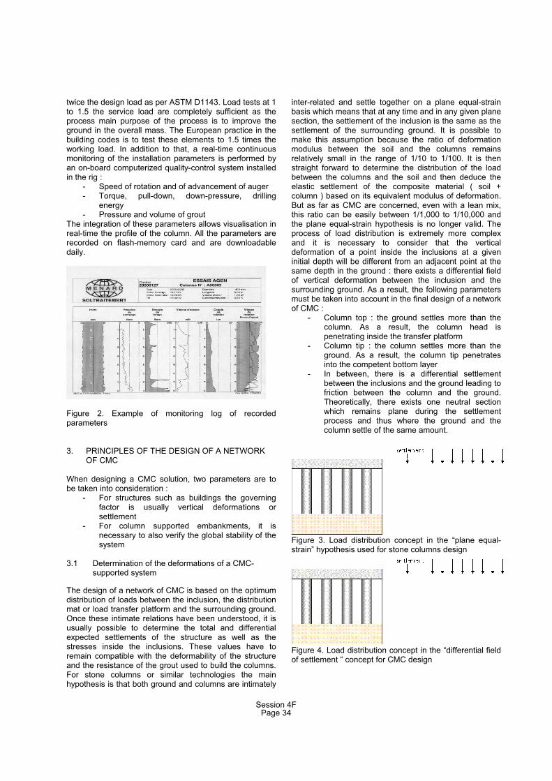
twice the design load as per ASTM D1143. Load tests at 1 to 1.5 the service load are completely sufficient as the process main purpose of the process is to improve the ground in the overall mass. The European practice in the building codes is to test these elements to 1.5 times the working load. In addition to that, a real-time continuousmonitoring of the installation parameters is performed byan on-board computerized quality-control system installed in the rig :
- Speed of rotation and of advancement of auger - Torque, pull-down, down-pressure, drilling
energy- Pressure and volume of grout
The integration of these parameters allows visualisation in real-time the profile of the column. All the parameters are recorded on flash-memory card and are downloadabledaily.
Figure 2. Example of monitoring log of recorded parameters
3. PRINCIPLES OF THE DESIGN OF A NETWORKOF CMC
When designing a CMC solution, two parameters are tobe taken into consideration :
- For structures such as buildings the governing factor is usually vertical deformations orsettlement
- For column supported embankments, it is necessary to also verify the global stability of the system
3.1 Determination of the deformations of a CMC-supported system
The design of a network of CMC is based on the optimumdistribution of loads between the inclusion, the distribution mat or load transfer platform and the surrounding ground.Once these intimate relations have been understood, it isusually possible to determine the total and differentialexpected settlements of the structure as well as thestresses inside the inclusions. These values have toremain compatible with the deformability of the structure and the resistance of the grout used to build the columns.For stone columns or similar technologies the mainhypothesis is that both ground and columns are intimately
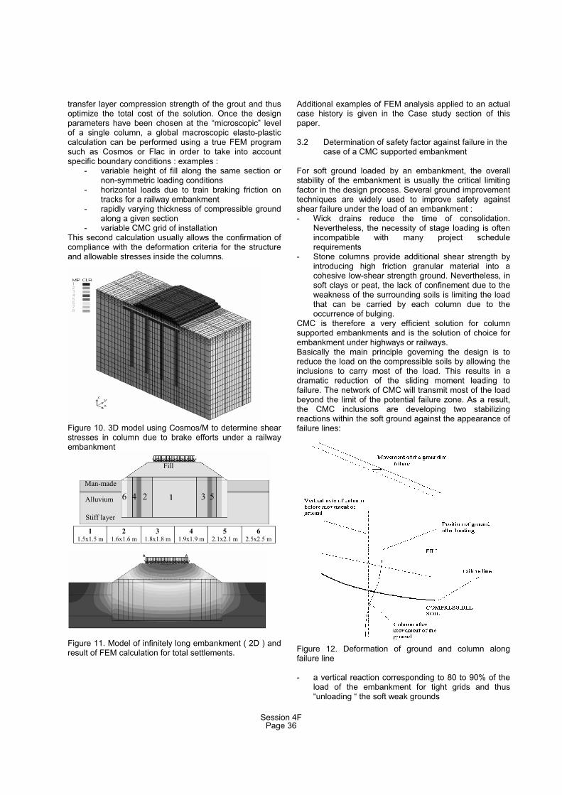
inter-related and settle together on a plane equal-strainbasis which means that at any time and in any given planesection, the settlement of the inclusion is the same as the settlement of the surrounding ground. It is possible tomake this assumption because the ratio of deformationmodulus between the soil and the columns remainsrelatively small in the range of 1/10 to 1/100. It is thenstraight forward to determine the distribution of the load between the columns and the soil and then deduce the elastic settlement of the composite material ( soil +column ) based on its equivalent modulus of deformation. But as far as CMC are concerned, even with a lean mix, this ratio can be easily between 1/1,000 to 1/10,000 and the plane equal-strain hypothesis is no longer valid. Theprocess of load distribution is extremely more complex and it is necessary to consider that the vertical deformation of a point inside the inclusions at a given initial depth will be different from an adjacent point at thesame depth in the ground : there exists a differential field of vertical deformation between the inclusion and the surrounding ground. As a result, the following parameters must be taken into account in the final design of a networkof CMC :
- Column top : the ground settles more than the column. As a result, the column head is penetrating inside the transfer platform
- Column tip : the column settles more than the ground. As a result, the column tip penetratesinto the competent bottom layer
- In between, there is a differential settlement between the inclusions and the ground leading to friction between the column and the ground. Theoretically, there exists one neutral section which remains plane during the settlement process and thus where the ground and the column settle of the same amount.
Figure 3. Load distribution concept in the “plane equal-strain” hypothesis used for stone columns design
Figure 4. Load distribution concept in the “differential fieldof settlement “ concept for CMC design
Session 4FPage 34

Figure 5. Principle of interaction CMC – distribution mat
As a result, displacement and stresses are given by thefollowing conceptual charts.
Figure 6. Load transfer, settlement and stress for CMC design
As a result, as far as stresses are concerned, above theneutral point, the column is subject to negative skinfriction : the load is transferred from the ground to the column and the stresses inside the column increases toreach a maximum at the neutral point. Below this point,the column is subject to positive skin friction : the load istransferred from the column to the ground and the column is progressively discharged with a decrease of the internal compression stress. This scheme is valid assuming a deformable distribution platform which willallow the punching of the column to occur. In case of a rigid slab, the infinitely-rigid beam hypothesis isgoverning the stress distribution and the neutral point is directly located under the slab. The deformation of the column and the platform are equal at that point bydefinition and the stress in the columns is maximal just under the slab. In that case CMC are functioning like friction piles. Although hand calculations are possible given a certain number of approximations and assumptions, the finite element analysis has proven to be the most reliable method to accurately predict the behaviour of the structures founded on CMC. FEM and finite difference analysis models can take into account :
- the behaviour of the column top and bottom withplastification into the mat and into the competent layer
- strain-stress relation for the CMC grout
- strain-stress relation for the ground depending onthe type of soils
- load transfer between columns and ground bothways ( from column to ground and ground to column )
Figure 7. Definition of influence zone of single column
Usually, the calculations are performed in two steps. In afirst step, an analysis if performed at the level of a unit cell of the installation network ( single column model ) using an axysymmetrical hypothesis for the model.
Figure 8. Axysymmetric analysis of a unit cell
Figure 9. Example of axysymmetric calculation using Plaxis
This axysymmetric calculation is usually performed using PLAXIS and allows to design the grid of installation, thenecessity of reinforcement by geotextile in the transfer layer as well as the stresses in the ground and in the column resulting of the stress distribution model. It is thus possible to refine the design parameters such as diameter of the columns, grid of installation, thickness of the
Session 4FPage 35
transfer layer compression strength of the grout and thusoptimize the total cost of the solution. Once the design parameters have been chosen at the “microscopic” levelof a single column, a global macroscopic elasto-plastic calculation can be performed using a true FEM program such as Cosmos or Flac in order to take into accountspecific boundary conditions : examples :
- variable height of fill along the same section or non-symmetric loading conditions
- horizontal loads due to train braking friction on tracks for a railway embankment
- rapidly varying thickness of compressible groundalong a given section
- variable CMC grid of installation This second calculation usually allows the confirmation ofcompliance with the deformation criteria for the structureand allowable stresses inside the columns.
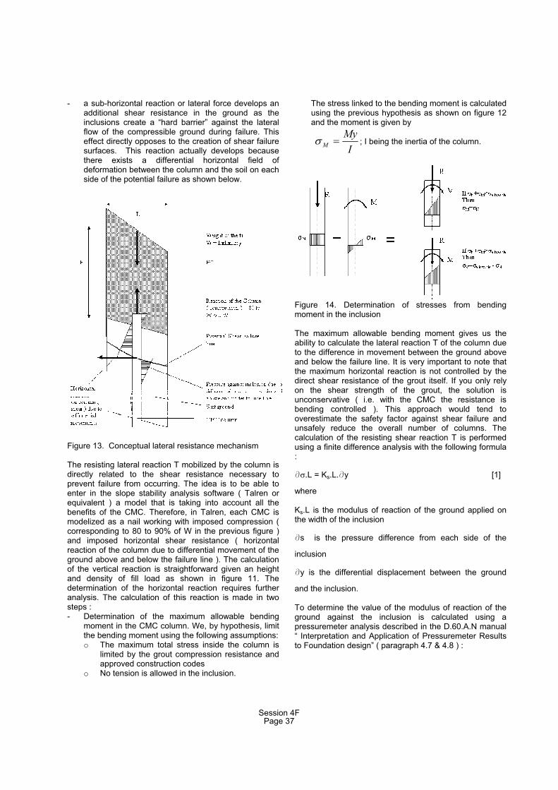
Figure 10. 3D model using Cosmos/M to determine shear stresses in column due to brake efforts under a railwayembankment
1
1.5x1.5 m
2
1.6x1.6 m
3
1.8x1.8 m
4
1.9x1.9 m
5
2.1x2.1 m
6
2.5x2.5 m
Figure 11. Model of infinitely long embankment ( 2D ) and result of FEM calculation for total settlements.
Additional examples of FEM analysis applied to an actual case history is given in the Case study section of this paper.
3.2 Determination of safety factor against failure in the case of a CMC supported embankment
For soft ground loaded by an embankment, the overallstability of the embankment is usually the critical limiting factor in the design process. Several ground improvement techniques are widely used to improve safety againstshear failure under the load of an embankment : - Wick drains reduce the time of consolidation.
Nevertheless, the necessity of stage loading is often incompatible with many project schedulerequirements
- Stone columns provide additional shear strength byintroducing high friction granular material into a cohesive low-shear strength ground. Nevertheless, in soft clays or peat, the lack of confinement due to theweakness of the surrounding soils is limiting the load that can be carried by each column due to theoccurrence of bulging.
CMC is therefore a very efficient solution for columnsupported embankments and is the solution of choice forembankment under highways or railways.Basically the main principle governing the design is to reduce the load on the compressible soils by allowing the inclusions to carry most of the load. This results in a dramatic reduction of the sliding moment leading to failure. The network of CMC will transmit most of the load beyond the limit of the potential failure zone. As a result, the CMC inclusions are developing two stabilizingreactions within the soft ground against the appearance offailure lines:
Figure 12. Deformation of ground and column alongfailure line
- a vertical reaction corresponding to 80 to 90% of the load of the embankment for tight grids and thus “unloading “ the soft weak grounds
Fill
Man-made
6Alluvium
Stiff layer
12 34 5
Session 4FPage 36
- a sub-horizontal reaction or lateral force develops an additional shear resistance in the ground as the inclusions create a “hard barrier” against the lateral
y to
o No tension is allowed in the inclusion.
inand
flow of the compressible ground during failure. Thiseffect directly opposes to the creation of shear failure surfaces. This reaction actually develops because there exists a differential horizontal field ofdeformation between the column and the soil on eachside of the potential failure as shown below.
Figure 13. Conceptual lateral resistance mechanism
The resisting lateral reaction T mobilized by the column isdirectly related to the shear resistance necessarprevent failure from occurring. The idea is to be able to enter in the slope stability analysis software ( Talren or equivalent ) a model that is taking into account all the benefits of the CMC. Therefore, in Talren, each CMC ismodelized as a nail working with imposed compression ( corresponding to 80 to 90% of W in the previous figure ) and imposed horizontal shear resistance ( horizontalreaction of the column due to differential movement of the ground above and below the failure line ). The calculation of the vertical reaction is straightforward given an height and density of fill load as shown in figure 11. Thedetermination of the horizontal reaction requires further analysis. The calculation of this reaction is made in twosteps : - Determination of the maximum allowable bending
moment in the CMC column. We, by hypothesis, limitthe bending moment using the following assumptions: o The maximum total stress inside the column is
limited by the grout compression resistance and approved construction codes
The stress linked to the bending moment is calculated us g the previous hypothesis as shown on figure 12
the moment is given by
IM ; I being the inertia of the column.
My
Figure 14. Determination of stresses from bendingmoment in the inclusion
The maximum allowable bending moment gives us theability to calculate the lateral reaction T of the column due to the difference in movement between the ground above and below the failure line. It is very important to note that
ence from each side of the
lusion.
lysis described in the D.60.A.N manualInterpretation and Application of Pressuremeter Results
the maximum horizontal reaction is not controlled by the direct shear resistance of the grout itself. If you only relyon the shear strength of the grout, the solution isunconservative ( i.e. with the CMC the resistance isbending controlled ). This approach would tend tooverestimate the safety factor against shear failure andunsafely reduce the overall number of columns. Thecalculation of the resisting shear reaction T is performedusing a finite difference analysis with the following formula:
c .L = Ks.L.cy [1]
where
Ks.L is the modulus of reaction of the ground applied on the width of the inclusion
cs is the pressure differ
inclusion
cy is the differential displacement between the ground
and the inc
To determine the value of the modulus of reaction of theground against the inclusion is calculated using apressuremeter ana“to Foundation design” ( paragraph 4.7 & 4.8 ) :
Session 4FPage 37

65.2.3
4
.6. M
s
EBKLong term : [2]
short term :
65.2.3
4
.12. M
s
EBK [3]
The loop calculation gives the horizontal shear stress in
igure 15. Deformation, stresses and moment in columns
he value of horizontal reaction T and vertical reaction R
. CASE STUDY
.1 Test section – Agen ( France )
.1.1 Description of the test section
his project is part of the test section program developed
- ns are covered by a distribution mat made of
- ement
-
- a first
the inclusions which corresponds to the deformation of theground and column that gives the maximum allowablebending moment already calculated.
F
Tare then entered into Talren model where each CMC column is modelled as a soil nail with imposedcompression and shear.
4
4
4
Tjointly with bureau Veritas in France in order to update the building design codes and recommendations to engineers to take into account the recent developments with theCMC technology. The test section procedure is as follows:- 9 CMC columns diameter 0.40 m are performed on a
3.0m x 3.0m square grid – depth of the column is 8.5mColumroller compacted granular fill of 0.40m thickness
- A concrete slab 15cm thick with no steelreinforcement is then placed on top of the matThe area is instrumented with 1 multidepth settlgage, 4 settlement plates on top of the slab and 9 total stress gages directly under the slab A reference test section is also installed adjacent tothe CMC area without any treatment to be able tocompare the results with the CMC test section The CMC test area has been loaded with 3m instep then 5m. the top of the embankment was 12m x 12m in order to be as close as possible to an infinite
embankment hypothesis. The reference test section was loaded with 3m of fill.
Figure 16. CMC test section set-up
4.1.2 Soil Profile
The soil characteristics were determined using pressuremeter tests in the test section area. The valuesgiven below are average values :
Table 1. Soil profile – Pressuremeter characteristics
4.1.3 Stress measurement - Settlement Results
The pressure sensors gave an overall distribution of stresses in agreement with the model described above. The sensors were installed just below the slab. The stress measured by the sensors located at ¼ of the grid gave a value of 50% of the full weight of the fill surchargeindicating that the load transfer between the CMC and the
Session 4FPage 38
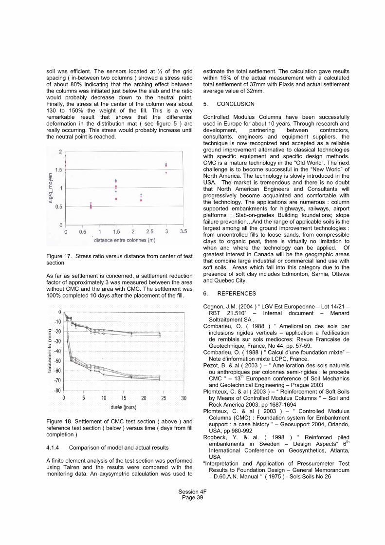
soil was efficient. The sensors located at ½ of the grid spacing ( in-between two columns ) showed a stress ratioof about 80% indicating that the arching effect betweenthe columns was initiated just below the slab and the ratiowould probably decrease down to the neutral point.Finally, the stress at the center of the column was about 130 to 150% the weight of the fill. This is a veryremarkable result that shows that the differentialdeformation in the distribution mat ( see figure 5 ) are really occurring. This stress would probably increase until the neutral point is reached.
igure 17. Stress ratio versus distance from center of test
s far as settlement is concerned, a settlement reduction
igure 18. Settlement of CMC test section ( above ) and
.1.4 Comparison of model and actual results
finite element analysis of the test section was performed
. CONCLUSION
ontrolled Modulus Columns have been successfully
. REFERENCES
ognon, J.M. (2004 ) “ LGV Est Europeenne – Lot 14/21 –
C 88 ) “ Amelioration des sols par
C ation mixte” –
P s sols naturels
Plomteux, C. & al ( 2003 ) – “ Reinforcement of Soft Soils
Plomteux, C. & al ( 2003 ) – “ Controlled Modulus
Rogbeck, Y. & al. ( 1998 ) “ Reinforced piled
“Interpretation and Application of Pressuremeter Test
Fsection
Afactor of approximately 3 was measured between the area without CMC and the area with CMC. The settlement was100% completed 10 days after the placement of the fill.
Freference test section ( below ) versus time ( days from fill completion )
4
Ausing Talren and the results were compared with themonitoring data. An axysymetric calculation was used to
estimate the total settlement. The calculation gave results within 15% of the actual measurement with a calculated total settlement of 37mm with Plaxis and actual settlement average value of 32mm.
5
Cused in Europe for about 10 years. Through research anddevelopment, partnering between contractors,consultants, engineers and equipment suppliers, the technique is now recognized and accepted as a reliable ground improvement alternative to classical technologies with specific equipment and specific design methods. CMC is a mature technology in the “Old World”. The next challenge is to become successful in the “New World” of North America. The technology is slowly introduced in the USA. The market is tremendous and there is no doubtthat North American Engineers and Consultants willprogressively become acquainted and comfortable withthe technology. The applications are numerous : column supported embankments for highways, railways, airport platforms ; Slab-on-grades Building foundations; slopefailure prevention…And the range of applicable soils is the largest among all the ground improvement technologies :from uncontrolled fills to loose sands, from compressibleclays to organic peat, there is virtually no limitation to when and where the technology can be applied. Of greatest interest in Canada will be the geographic areasthat combine large industrial or commercial land use withsoft soils. Areas which fall into this category due to thepresence of soft clay includes Edmonton, Sarnia, Ottawaand Quebec City.
6
CRBT 21.510” – Internal document – MenardSoltraitement SA .
ombarieu, O. ( 19inclusions rigides verticals – application a l’edification de remblais sur sols mediocres: Revue Francaise deGeotechnique, France, No 44, pp. 57-59.
ombarieu, O. ( 1988 ) “ Calcul d’une foundNote d’information mixte LCPC, France.
ezot, B. & al ( 2003 ) – “ Amelioration deou anthropiques par colonnes semi-rigides : le procede CMC “ – 13th European conference of Soil Mechanics and Geotechnical Engineering – Prague 2003
by Means of Controlled Modulus Columns “ – Soil and Rock America 2003, pp 1687-1694
Columns (CMC) : Foundation system for Embankmentsupport : a case history “ – Geosupport 2004, Orlando, USA, pp 980-992
embankments in Sweden – Design Aspects” 6th
International Conference on Geosynthetics, Atlanta,USA
Results to Foundation Design – General Memorandum– D.60.A.N. Manual “ ( 1975 ) - Sols Soils No 26
Session 4FPage 39