Closed loop pulsating heat pipes Part A: parametric...
12
Closed loop pulsating heat pipes Part A: parametric experimental investigations Piyanun Charoensawan a , Sameer Khandekar b, * , Manfred Groll b , Pradit Terdtoon a a Department of Mechanical Engineering, Chiang Mai University, 50200 Chiang Mai, Thailand b Institut f€ ur Kernenergetik und Energiesysteme (IKE), Universit€ at Stuttgart, Pfaffenwaldring 31, 70569 Stuttgart, Germany Received 4 April 2003; accepted 1 May 2003 Abstract Closed loop pulsating heat pipes (CLPHPs) are complex heat transfer devices having a strong thermo- hydrodynamic coupling governing the thermal performance. In this paper, a wide range of pulsating heat pipes is experimentally studied thereby providing vital information on the parameter dependency of their thermal performance. The influence characterization has been done for the variation of internal diameter, number of turns, working fluid and inclination angle (from vertical bottom heat mode to horizontal ori- entation mode) of the device. CLPHPs are made of copper tubes of internal diameters 2.0 and 1.0 mm, heated by constant temperature water bath and cooled by constant temperature water–ethylene glycol mixture (50% each by volume). The number of turns in the evaporator is varied from 5 to 23. The working fluids employed are water, ethanol and R-123. The results indicate a strong influence of gravity and number of turns on the performance. The thermophysical properties of working fluids affect the performance which also strongly depends on the boundary conditions of PHP operation. Part B of this paper, which deals with development of semi-empirical correlations to fit the data reported here coupled with some critical visu- alization results, will appear separately. Ó 2003 Elsevier Ltd. All rights reserved. Keywords: Pulsating heat pipe; Parametric experimental study * Corresponding author: Tel.: +49-711-685-2142; fax: +49-711-685-2010. E-mail address: [email protected] (S. Khandekar). 1359-4311/$ - see front matter Ó 2003 Elsevier Ltd. All rights reserved. doi:10.1016/S1359-4311(03)00159-5 Applied Thermal Engineering 23 (2003) 2009–2020 www.elsevier.com/locate/apthermeng
Transcript of Closed loop pulsating heat pipes Part A: parametric...
Applied Thermal Engineering 23 (2003) 2009–2020www.elsevier.com/locate/apthermeng
Closed loop pulsating heat pipes
Part A: parametric experimental investigations
Piyanun Charoensawan a, Sameer Khandekar b,*, Manfred Groll b,Pradit Terdtoon a
a Department of Mechanical Engineering, Chiang Mai University, 50200 Chiang Mai, Thailandb Institut f€uur Kernenergetik und Energiesysteme (IKE), Universit€aat Stuttgart, Pfaffenwaldring 31,
70569 Stuttgart, Germany
Received 4 April 2003; accepted 1 May 2003
Abstract
Closed loop pulsating heat pipes (CLPHPs) are complex heat transfer devices having a strong thermo-
hydrodynamic coupling governing the thermal performance. In this paper, a wide range of pulsating heatpipes is experimentally studied thereby providing vital information on the parameter dependency of their
thermal performance. The influence characterization has been done for the variation of internal diameter,
number of turns, working fluid and inclination angle (from vertical bottom heat mode to horizontal ori-
entation mode) of the device. CLPHPs are made of copper tubes of internal diameters 2.0 and 1.0 mm,
heated by constant temperature water bath and cooled by constant temperature water–ethylene glycol
mixture (50% each by volume). The number of turns in the evaporator is varied from 5 to 23. The working
fluids employed are water, ethanol and R-123. The results indicate a strong influence of gravity and number
of turns on the performance. The thermophysical properties of working fluids affect the performance whichalso strongly depends on the boundary conditions of PHP operation. Part B of this paper, which deals with
development of semi-empirical correlations to fit the data reported here coupled with some critical visu-
alization results, will appear separately.
� 2003 Elsevier Ltd. All rights reserved.
Keywords: Pulsating heat pipe; Parametric experimental study
* Corresponding author: Tel.: +49-711-685-2142; fax: +49-711-685-2010.
E-mail address: [email protected] (S. Khandekar).
1359-4311/$ - see front matter � 2003 Elsevier Ltd. All rights reserved.
doi:10.1016/S1359-4311(03)00159-5
Nomenclature
D tube diameter, mg acceleration due to gravity, m/s2
L length, mN number of turns_QQ heat transfer rate, Wb inclination angle from horizontal axis
Subscripts
a adiabatic sectionc condenser sectioncrit critical valuee evaporator sectioni innermax maximum
2010 P. Charoensawan et al. / Applied Thermal Engineering 23 (2003) 2009–2020
1. Introduction
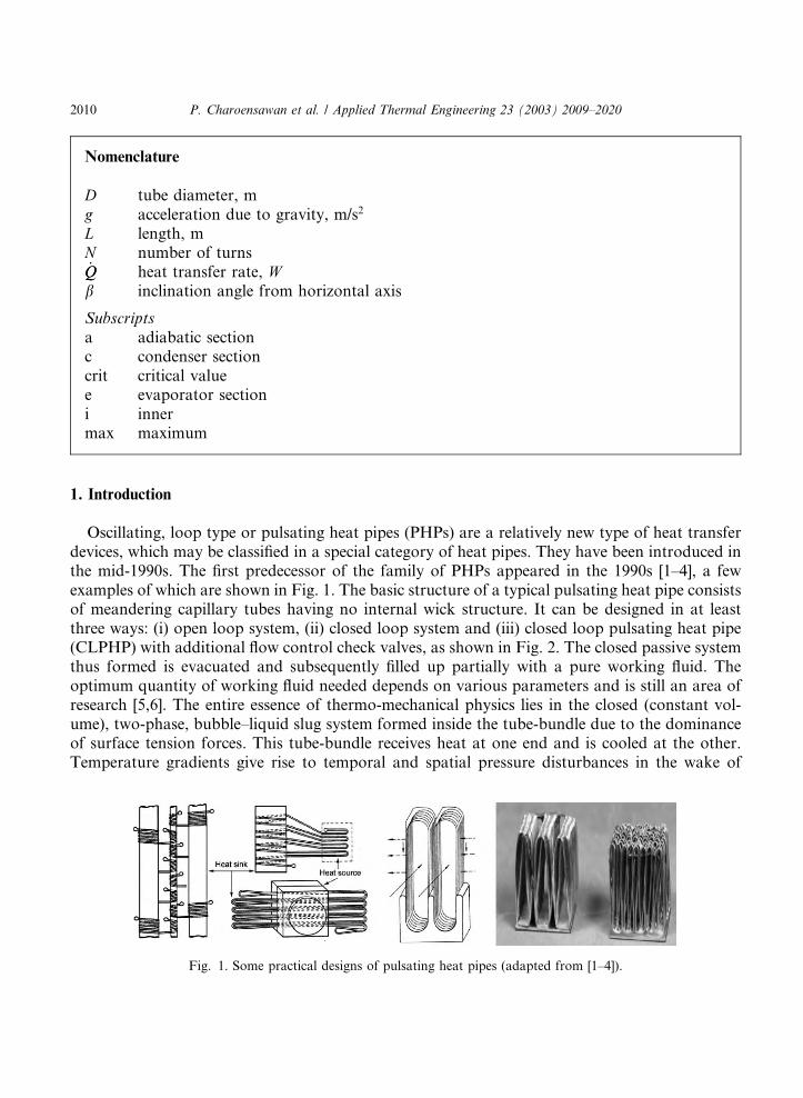
Oscillating, loop type or pulsating heat pipes (PHPs) are a relatively new type of heat transferdevices, which may be classified in a special category of heat pipes. They have been introduced inthe mid-1990s. The first predecessor of the family of PHPs appeared in the 1990s [1–4], a fewexamples of which are shown in Fig. 1. The basic structure of a typical pulsating heat pipe consistsof meandering capillary tubes having no internal wick structure. It can be designed in at leastthree ways: (i) open loop system, (ii) closed loop system and (iii) closed loop pulsating heat pipe(CLPHP) with additional flow control check valves, as shown in Fig. 2. The closed passive systemthus formed is evacuated and subsequently filled up partially with a pure working fluid. Theoptimum quantity of working fluid needed depends on various parameters and is still an area ofresearch [5,6]. The entire essence of thermo-mechanical physics lies in the closed (constant vol-ume), two-phase, bubble–liquid slug system formed inside the tube-bundle due to the dominanceof surface tension forces. This tube-bundle receives heat at one end and is cooled at the other.Temperature gradients give rise to temporal and spatial pressure disturbances in the wake of
Fig. 1. Some practical designs of pulsating heat pipes (adapted from [1–4]).
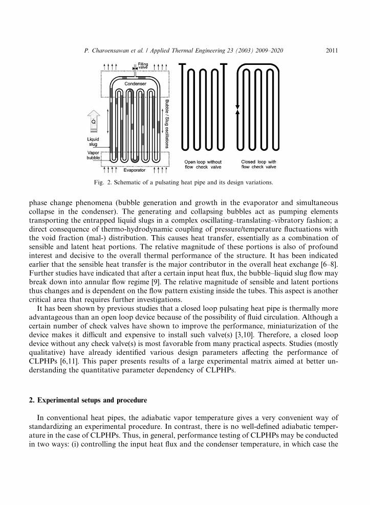
Fig. 2. Schematic of a pulsating heat pipe and its design variations.
P. Charoensawan et al. / Applied Thermal Engineering 23 (2003) 2009–2020 2011
phase change phenomena (bubble generation and growth in the evaporator and simultaneouscollapse in the condenser). The generating and collapsing bubbles act as pumping elementstransporting the entrapped liquid slugs in a complex oscillating–translating–vibratory fashion; adirect consequence of thermo-hydrodynamic coupling of pressure/temperature fluctuations withthe void fraction (mal-) distribution. This causes heat transfer, essentially as a combination ofsensible and latent heat portions. The relative magnitude of these portions is also of profoundinterest and decisive to the overall thermal performance of the structure. It has been indicatedearlier that the sensible heat transfer is the major contributor in the overall heat exchange [6–8].Further studies have indicated that after a certain input heat flux, the bubble–liquid slug flow maybreak down into annular flow regime [9]. The relative magnitude of sensible and latent portionsthus changes and is dependent on the flow pattern existing inside the tubes. This aspect is anothercritical area that requires further investigations.
It has been shown by previous studies that a closed loop pulsating heat pipe is thermally moreadvantageous than an open loop device because of the possibility of fluid circulation. Although acertain number of check valves have shown to improve the performance, miniaturization of thedevice makes it difficult and expensive to install such valve(s) [3,10]. Therefore, a closed loopdevice without any check valve(s) is most favorable from many practical aspects. Studies (mostlyqualitative) have already identified various design parameters affecting the performance ofCLPHPs [6,11]. This paper presents results of a large experimental matrix aimed at better un-derstanding the quantitative parameter dependency of CLPHPs.
2. Experimental setups and procedure
In conventional heat pipes, the adiabatic vapor temperature gives a very convenient way ofstandardizing an experimental procedure. In contrast, there is no well-defined adiabatic temper-ature in the case of CLPHPs. Thus, in general, performance testing of CLPHPs may be conductedin two ways: (i) controlling the input heat flux and the condenser temperature, in which case the
2012 P. Charoensawan et al. / Applied Thermal Engineering 23 (2003) 2009–2020
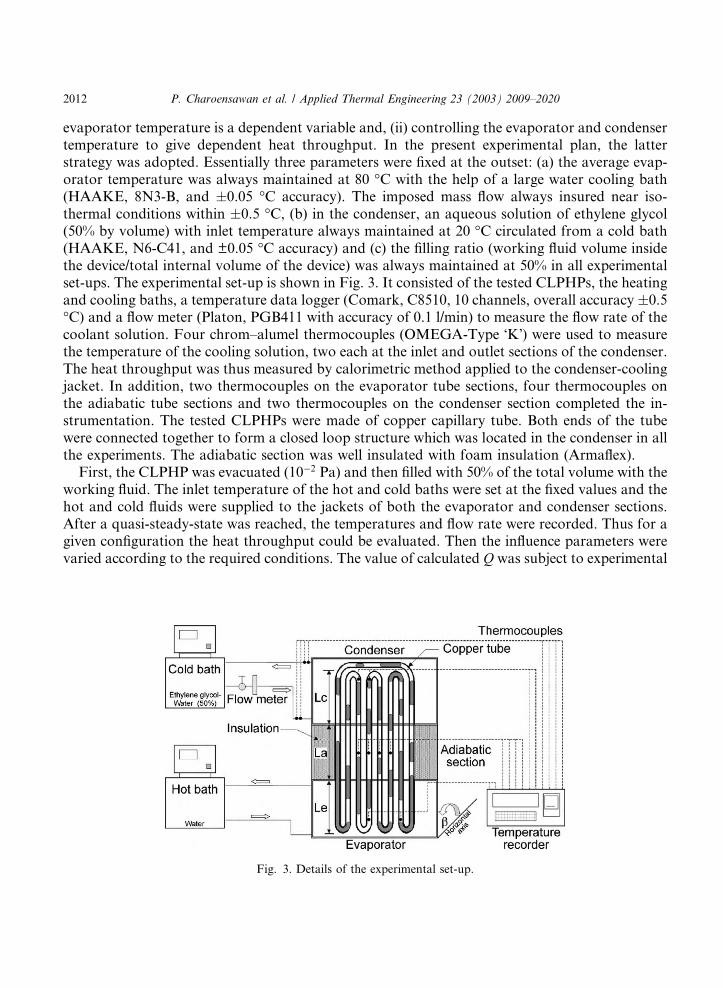
evaporator temperature is a dependent variable and, (ii) controlling the evaporator and condensertemperature to give dependent heat throughput. In the present experimental plan, the latterstrategy was adopted. Essentially three parameters were fixed at the outset: (a) the average evap-orator temperature was always maintained at 80 �C with the help of a large water cooling bath(HAAKE, 8N3-B, and �0.05 �C accuracy). The imposed mass flow always insured near iso-thermal conditions within �0.5 �C, (b) in the condenser, an aqueous solution of ethylene glycol(50% by volume) with inlet temperature always maintained at 20 �C circulated from a cold bath(HAAKE, N6-C41, and ±0.05 �C accuracy) and (c) the filling ratio (working fluid volume insidethe device/total internal volume of the device) was always maintained at 50% in all experimentalset-ups. The experimental set-up is shown in Fig. 3. It consisted of the tested CLPHPs, the heatingand cooling baths, a temperature data logger (Comark, C8510, 10 channels, overall accuracy �0.5�C) and a flow meter (Platon, PGB411 with accuracy of 0.1 l/min) to measure the flow rate of thecoolant solution. Four chrom–alumel thermocouples (OMEGA-Type �K�) were used to measurethe temperature of the cooling solution, two each at the inlet and outlet sections of the condenser.The heat throughput was thus measured by calorimetric method applied to the condenser-coolingjacket. In addition, two thermocouples on the evaporator tube sections, four thermocouples onthe adiabatic tube sections and two thermocouples on the condenser section completed the in-strumentation. The tested CLPHPs were made of copper capillary tube. Both ends of the tubewere connected together to form a closed loop structure which was located in the condenser in allthe experiments. The adiabatic section was well insulated with foam insulation (Armaflex).
First, the CLPHP was evacuated (10�2 Pa) and then filled with 50% of the total volume with theworking fluid. The inlet temperature of the hot and cold baths were set at the fixed values and thehot and cold fluids were supplied to the jackets of both the evaporator and condenser sections.After a quasi-steady-state was reached, the temperatures and flow rate were recorded. Thus for agiven configuration the heat throughput could be evaluated. Then the influence parameters werevaried according to the required conditions. The value of calculated Q was subject to experimental
Fig. 3. Details of the experimental set-up.
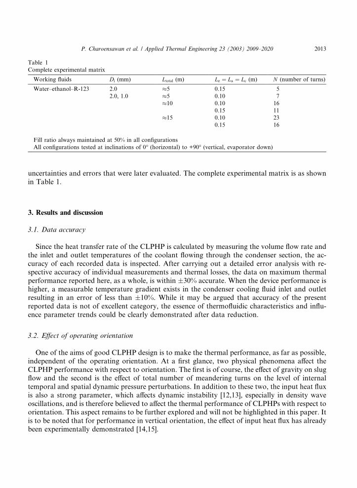
Table 1
Complete experimental matrix
Working fluids Di (mm) Ltotal (m) Le ¼ La ¼ Lc (m) N (number of turns)
Water–ethanol–R-123 2.0 �5 0.15 5
2.0, 1.0 �5 0.10 7
�10 0.10 16
0.15 11
�15 0.10 23
0.15 16
Fill ratio always maintained at 50% in all configurations
All configurations tested at inclinations of 0� (horizontal) to +90� (vertical, evaporator down)
P. Charoensawan et al. / Applied Thermal Engineering 23 (2003) 2009–2020 2013
uncertainties and errors that were later evaluated. The complete experimental matrix is as shownin Table 1.
3. Results and discussion
3.1. Data accuracy
Since the heat transfer rate of the CLPHP is calculated by measuring the volume flow rate andthe inlet and outlet temperatures of the coolant flowing through the condenser section, the ac-curacy of each recorded data is inspected. After carrying out a detailed error analysis with re-spective accuracy of individual measurements and thermal losses, the data on maximum thermalperformance reported here, as a whole, is within �30% accurate. When the device performance ishigher, a measurable temperature gradient exists in the condenser cooling fluid inlet and outletresulting in an error of less than �10%. While it may be argued that accuracy of the presentreported data is not of excellent category, the essence of thermofluidic characteristics and influ-ence parameter trends could be clearly demonstrated after data reduction.
3.2. Effect of operating orientation
One of the aims of good CLPHP design is to make the thermal performance, as far as possible,independent of the operating orientation. At a first glance, two physical phenomena affect theCLPHP performance with respect to orientation. The first is of course, the effect of gravity on slugflow and the second is the effect of total number of meandering turns on the level of internaltemporal and spatial dynamic pressure perturbations. In addition to these two, the input heat fluxis also a strong parameter, which affects dynamic instability [12,13], especially in density waveoscillations, and is therefore believed to affect the thermal performance of CLPHPs with respect toorientation. This aspect remains to be further explored and will not be highlighted in this paper. Itis to be noted that for performance in vertical orientation, the effect of input heat flux has alreadybeen experimentally demonstrated [14,15].
2014 P. Charoensawan et al. / Applied Thermal Engineering 23 (2003) 2009–2020
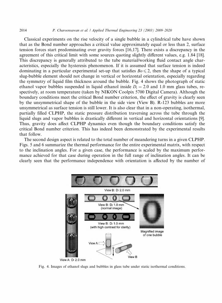
Classical experiments on the rise velocity of a single bubble in a cylindrical tube have shownthat as the Bond number approaches a critical value approximately equal or less than 2, surfacetension forces start predominating over gravity forces [16,17]. There exists a discrepancy in theagreement of this critical limit with some sources quoting slightly different values, e.g. 1.84 [18].This discrepancy is generally attributed to the tube material/working fluid contact angle char-acteristics, especially the hysteresis phenomenon. If it is assumed that surface tension is indeeddominating in a particular experimental set-up that satisfies Bo6 2, then the shape of a typicalslug-bubble element should not change in vertical or horizontal orientation, especially regardingthe symmetry of liquid film thickness around the bubble. Fig. 4 shows the photograph of staticethanol vapor bubbles suspended in liquid ethanol inside Di ¼ 2:0 and 1.0 mm glass tubes, re-spectively, at room temperature (taken by NIKON Coolpix 5700 Digital Camera). Although theboundary conditions meet the critical Bond number criterion, the effect of gravity is clearly seenby the unsymmetrical shape of the bubble in the side view (View B). R-123 bubbles are moreunsymmetrical as surface tension is still lower. It is also clear that in a non-operating, isothermal,partially filled CLPHP, the static pressure distribution traversing across the tube through theliquid slugs and vapor bubbles is drastically different in vertical and horizontal orientations [9].Thus, gravity does affect CLPHP dynamics even though the boundary conditions satisfy thecritical Bond number criterion. This has indeed been demonstrated by the experimental resultsthat follow.
The second design aspect is related to the total number of meandering turns in a given CLPHP.Figs. 5 and 6 summarize the thermal performance for the entire experimental matrix, with respectto the inclination angles. For a given case, the performance is scaled by the maximum perfor-mance achieved for that case during operation in the full range of inclination angles. It can beclearly seen that the performance independence with orientation is affected by the number of
Fig. 4. Images of ethanol slugs and bubbles in glass tube under static isothermal conditions.

Fig. 5. Thermal performance for Di ¼ 2 mm: (a) N > Ncrit and (b) N < Ncrit.
P. Charoensawan et al. / Applied Thermal Engineering 23 (2003) 2009–2020 2015
turns. For Di ¼ 2:0 mm devices, the effect could be clearly separated into two cases by using acertain critical value of number of turns (Ncrit). In this case, the critical number of turns wasapproximately 16 turns (with the exception of Le ¼ 15 cm, 16 turns and ethanol as working fluid).In case of Di ¼ 1:0 mm devices too, similar trends are seen as depicted in Fig. 6(a) and (b). Forthis case, the critical value of number of turns tends to be higher than for 2 mm tubes. In addition,for 1 mm tubes, measurable heat transfer was not possible with water filled devices in the entirerange of operating orientation.
When N is less than a certain Ncrit, the CLPHP cannot satisfactorily operate in the horizontalorientation and vice versa. For N < Ncrit, the highest thermal performance normally occurs atvertical bottom heating mode decreasing continuously as the device is turned towards horizontal.
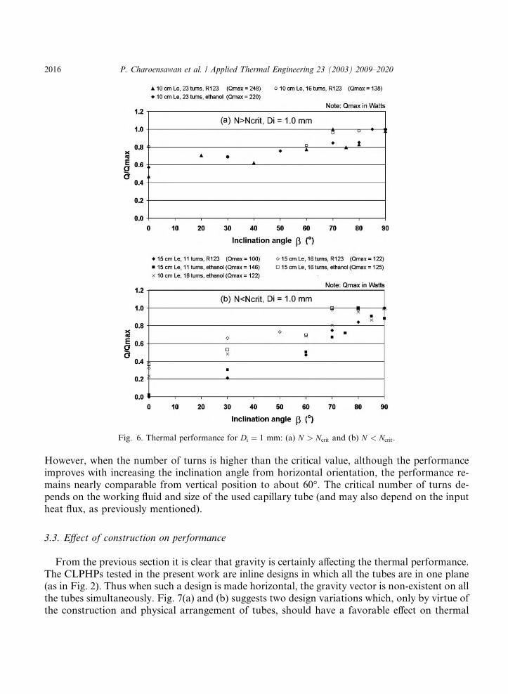
Fig. 6. Thermal performance for Di ¼ 1 mm: (a) N > Ncrit and (b) N < Ncrit.
2016 P. Charoensawan et al. / Applied Thermal Engineering 23 (2003) 2009–2020
However, when the number of turns is higher than the critical value, although the performanceimproves with increasing the inclination angle from horizontal orientation, the performance re-mains nearly comparable from vertical position to about 60�. The critical number of turns de-pends on the working fluid and size of the used capillary tube (and may also depend on the inputheat flux, as previously mentioned).
3.3. Effect of construction on performance
From the previous section it is clear that gravity is certainly affecting the thermal performance.The CLPHPs tested in the present work are inline designs in which all the tubes are in one plane(as in Fig. 2). Thus when such a design is made horizontal, the gravity vector is non-existent on allthe tubes simultaneously. Fig. 7(a) and (b) suggests two design variations which, only by virtue ofthe construction and physical arrangement of tubes, should have a favorable effect on thermal
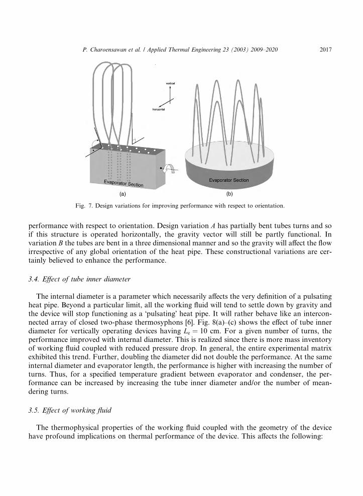
Fig. 7. Design variations for improving performance with respect to orientation.
P. Charoensawan et al. / Applied Thermal Engineering 23 (2003) 2009–2020 2017
performance with respect to orientation. Design variation A has partially bent tubes turns and soif this structure is operated horizontally, the gravity vector will still be partly functional. Invariation B the tubes are bent in a three dimensional manner and so the gravity will affect the flowirrespective of any global orientation of the heat pipe. These constructional variations are cer-tainly believed to enhance the performance.
3.4. Effect of tube inner diameter
The internal diameter is a parameter which necessarily affects the very definition of a pulsatingheat pipe. Beyond a particular limit, all the working fluid will tend to settle down by gravity andthe device will stop functioning as a �pulsating� heat pipe. It will rather behave like an intercon-nected array of closed two-phase thermosyphons [6]. Fig. 8(a)–(c) shows the effect of tube innerdiameter for vertically operating devices having Le ¼ 10 cm. For a given number of turns, theperformance improved with internal diameter. This is realized since there is more mass inventoryof working fluid coupled with reduced pressure drop. In general, the entire experimental matrixexhibited this trend. Further, doubling the diameter did not double the performance. At the sameinternal diameter and evaporator length, the performance is higher with increasing the number ofturns. Thus, for a specified temperature gradient between evaporator and condenser, the per-formance can be increased by increasing the tube inner diameter and/or the number of mean-dering turns.
3.5. Effect of working fluid
The thermophysical properties of the working fluid coupled with the geometry of the devicehave profound implications on thermal performance of the device. This affects the following:

Fig. 8. Effect of diameter on the heat throughput (Le ¼ 100 mm, vertical orientation).
2018 P. Charoensawan et al. / Applied Thermal Engineering 23 (2003) 2009–2020
• the relative share of latent and sensible heat in the overall heat throughput;• the possibility of having different flow patterns in the device, e.g. slug–annular flow regime
inter-transition;• the average flow velocity and overall pressure drop (including effect of gravity);• bubble nucleation, collapse, shapes, agglomeration and breakage; bubble pumping action, etc.
In vertical orientation for the 2.0 mm devices, water filled devices showed higher performanceas compared to R-123 and ethanol. In contrast R-123 and ethanol showed comparable perfor-mance in case of 1.0 mm devices with water showing very poor results. This is seen in Fig. 9 and
Fig. 9. Effect of working fluid on the thermal performance.
P. Charoensawan et al. / Applied Thermal Engineering 23 (2003) 2009–2020 2019
also in Fig. 8. Water has a very high surface tension, a very low ðdP=dT Þsat, a very high latent andspecific heat and reasonably higher dynamic viscosity as compared to R-123. Since the thermalperformance is a complex combination of the above noted it is certainly difficult to prescribe orproscribe a certain working fluid unless all the boundary conditions are exactly known and in-dividual effects have been explicitly isolated and quantified.
4. Summary and conclusions
A range of closed loop pulsating heat pipes has been experimentally investigated to study theeffects of various influence parameters. The effect of internal diameter, operating inclination angle(gravity), working fluid and number of turns on the thermal performance has been demonstrated.The following main conclusions can be drawn from the study:
• Gravity certainly affects the heat throughput. Although the internal diameter of the tubes testedin the present study, as governed by the critical Bond number, is well within the specified limit,bubble shapes are affected by the buoyancy forces.
• A certain critical number of turns is required to make horizontal operation possible and also tobridge the performance gap between vertical and horizontal operation. This is attributed to theincrease in the level of internal perturbations.
• Different fluids are beneficial under different operating conditions. An optimum tradeoff of var-ious thermophysical properties has to be achieved depending on the imposed thermo-mechan-ical boundary conditions.
• For a given temperature differential, performance improves with increase in internal diameter.The internal diameter is a parameter which necessarily affects the very definition of a pulsatingheat pipe.
It may also be safely concluded that thermo-mechanical interactions and instabilities in apulsating heat pipe in particular, and in capillary sized tubes (mini-micro channels) in general, isquite complex and further experiments are indeed needed. The fact that pulsating heat pipes areclosed systems in which the velocity scale is dependent on the imposed thermal boundary con-ditions (and is not known a priori) makes it all the more difficult for analysis. This aspect, in-cluding semi-empirical modeling approach coupled with critical visualization results is addressedin Part B of this paper [19].
Acknowledgements
This research work was done jointly by Faculty of Engineering, Chiang Mai University,Thailand and Institut f€uur Kernenergetik und Energiesysteme (IKE), Universit€aat Stuttgart, Ger-many under the auspices of Royal Golden Jubilee Scholarship of the Thailand Research Fund(under Contract No.1.M.CM/43/A.1) and Deutscher Akademischer Austauschdienst (DAAD).The work was also partly supported by Deutsche Forschungsgemeinschaft (DFG) under GrantGR-412/33-1.
2020 P. Charoensawan et al. / Applied Thermal Engineering 23 (2003) 2009–2020
References
[1] H. Akachi, US Patent, Patent Number 4921041, 1990.
[2] H. Akachi, US Patent, Patent Number 5219020, 1993.
[3] H. Akachi, US Patent, Patent Number 5490558, 1996.
[4] H. Akachi, F. Pol�aa�ssek, P. �SStulc, Pulsating heat pipes, in: Proceedings of the 5th International Heat Pipe
Symposium, Melbourne, Australia, 1996, pp. 208–217.
[5] S. Khandekar, N. Dollinger, M. Groll, Understanding operational regimes of pulsating heat pipes: an experimental
study, Appl. Therm. Eng. 23 (6) (2003) 707–719 (ISSN 1359-4311).
[6] M. Groll, S. Khandekar, Pulsating heat pipes: a challenge and still unsolved problem in heat pipe science, Arch.
Thermodyn. 23 (4) (2002) 17–28 (ISSN 1231-0956).
[7] S. Nishio, S. Nagata, S. Baba, R. Shirakashi, Thermal performance of SEMOS heat pipes, in: Proceedings of 12th
International Heat Transfer Conference, Grenoble, France, vol. 4, 2002, pp. 477–482 (ISBN 2-84299-307-1).
[8] M. Shafii, A. Faghri, Y. Zhang, Thermal modeling of unlooped and looped pulsating heat pipes, ASME J. Heat
Transfer 123 (2001) 1159–1172.
[9] S. Khandekar, M. Groll, An insight into thermo-hydrodynamic coupling in pulsating heat pipes, Int. J. Therm. Sci.
(Rev. Gn. Therm.) in press (ISSN: 1290-0729).
[10] S. Duminy, Experimental investigation of pulsating heat pipes, Diploma Thesis, Institute of Nuclear Engineering
and Energy Systems (IKE), Universitt Stuttgart, Germany, 1998.
[11] S. Maezawa, K. Minamisawa, A. Gi, H. Akachi, Thermal performance of capillary tube thermosyphon, in:
Proceedings of the 9th International Heat Pipe Conference, Albuquerque, New Mexico, 1995.
[12] J. Boure, A. Bergles, L. Tong, Review of two-phase flow instability, Nucl. Eng. Design 25 (1973) 165–192.
[13] P. Saha, M. Ishii, N. Zuber, An experimental investigation of thermally induced flow oscillations in two-phase
systems, ASME J. Heat Transfer 98 (1976) 616–622.
[14] B. Tong, T. Wong, K. Ooi, Closed-loop pulsating heat pipe, Appl. Therm. Eng. 21 (18) (2001) 1845–1862 (ISSN
1359-4311).
[15] S. Khandekar, M. Groll, P. Charoensawan, P. Terdtoon, Pulsating heat pipes: thermo-fluidic characteristics and
comparative study with single phase thermosyphon, in: Proceedings of the 12th International Heat Transfer
Conference, Grenoble, France, vol. 4, 2002, pp. 459–464 (ISBN 2-84299-307-1).
[16] T. Harmathy, Velocity of large bubbles in media of infinite or restricted extent, AIChE J. 6 (2) (1960) 281–288.
[17] E. White, R. Beardmore, The velocity of rise of single cylindrical air bubbles through liquids contained in vertical
tubes, Chem. Eng. Sci. 17 (1962) 351–361.
[18] F. Bretherton, The motion of long bubbles in tubes, J. Fluid Mech. (10) (1961) 167–188.
[19] S. Khandekar, P. Charoensawan, M. Groll, P. Terdtoon, Closed loop pulsating heat pipes––part B: visualization
and semi-empirical modeling, Appl. Therm. Eng. (under review) (ISSN 1359-4311).