
Close-up ShadowBox 3 - Rafael Lozano-Hemmer · Close-up ShadowBox 3 By Rafael Lozano ......
48
Close-up ShadowBox 3 By Rafael Lozano-Hemmer CONTENTS General important information This short section must be read for proper operation Description Operation Cleaning Placement Instructions Software Detailed technical information A technical reference for preservation, maintenance and troubleshooting Components of the piece Troubleshooting Appendix 1 – Plasma mount technical sheet and installation manual Appendix 2 – Technical data sheet for AVT industrial camera Appendix 3 – Optics data sheet Appendix 4 – Shadowbox inside, cabling diagram and photographs Appendix 5 – Suggested lighting installation
Transcript of Close-up ShadowBox 3 - Rafael Lozano-Hemmer · Close-up ShadowBox 3 By Rafael Lozano ......

Close-upShadowBox 3By Rafael Lozano-Hemmer
CONTENTSGeneral important informationThis short section must be read for proper operation
DescriptionOperationCleaningPlacement InstructionsSoftware
Detailed technical informationA technical reference for preservation, maintenance and troubleshooting
Components of the pieceTroubleshootingAppendix 1 – Plasma mount technical sheet and installation manualAppendix 2 – Technical data sheet for AVT industrial cameraAppendix 3 – Optics data sheetAppendix 4 – Shadowbox inside, cabling diagram and photographsAppendix 5 – Suggested lighting installation

General important information

Close-up, ShadowBox 3 (2006), high-resolution display with integrated computerized tracking system, 104.5 x 80 x 12 cm. Edition of 6 +1APBy Rafael Lozano-Hemmer
Description
Close-up is the third piece of the ShadowBox series of interactive displays with a built-in computerized tracking system. This piece shows the viewer’s shadow revealing hundreds of tiny videos of other people who have recently looked at the work. When a viewer approaches the piece, the system automatically starts recording and makes a video of him or her. Simultaneously, inside the viewer’s silhouette videos are triggered that show up to 800 recent recordings. This piece presents a schizoid experience where our presence triggers a massive array of surveillance videos.
ShadowBox series: Derived from Lozano-Hemmer’s interest in portraiture, surveillance and phantasmagoria, ShadowBoxes are autonomous artworks but often are used as “platforms” or “digital sketches” for larger installations or environments.
Operation
1. Connect the box to electrical power using the supplied power cable. The Shadowbox comes with a standard IEC C14 chassis plug, which is found in most computers (see image below).
You may connect the piece to 100-120V 60Hz (American) or to 210-240V 50Hz (European) current, as all the gear inside has auto switching power supplies. The whole piece draws around 300W.
2. To turn the piece ON, firmly press the button that is on the lower back of the piece, on the right side. Important note: Once the button is pushed it takes up to 4 minutes for the display to start-up. Please do not push the button again as you will shut down the piece.
3. To turn the piece OFF, press the power button once.

Cleaning
Please do not clean the display surface with Windex or soap. Use a lint-free cloth and LCD screen liquid cleaner, such as Kensington Screen Guardian found in computer stores. The aluminium frame can be cleaned with a wet cloth and a bit of liquid soap.
Placement Instructions
The piece should be hung with the centre at 152 cm (60 inches) from the ground, using the provided “Peerless” plasma mounting system. Instructions for this are included in Appendix 1 of this manual. Ideally the piece should be mounted taking into consideration the following issues:
1. Place in a room that does not receive too much direct sunlight. The tracking system for the camera adapts to changing lighting conditions, for instance if a lighting fixture is added to the room the system will automatically remove the effects of this new light after a few minutes. However, if direct sunlight comes into the room and there are a some clouds in the sky it is possible that the system will track on the shadows of the clouds as if they were people. The system might also trigger a snapshot of this undesirable subject, populating the piece with seemingly empty backgrounds. This is an issue that can cause detriment only to the aesthetic performance of the piece.
2. Place so that the piece does not face a moving object such as a kinetic sculpture, a TV monitor, a visible elevator, a fluttering curtain, etc. Basically, the system will track anything that changes in front of the camera and include that in the “active” subjects. The only things it will ignore are those that are completely static. If the piece is in front of a TV monitor, for example, it will register the changing image as being an active subject, and that will interfere with the desired behavior of the software.
3. Ensure there is enough lighting in the room, in particular right in front of the piece. A painting or a photograph should be lit to be seen properly, but a Shadowbox contains a camera that needs to see the public properly. If the room does not have nice even illumination throughout you may want to add a fluorescent or dim floodlight, —on the same wall as the piece—, that illuminates the viewer, not the piece. (Refer to Appendix 5 for a collection of suggested lighting installations.) When installing an artificial light source, ideally you should choose one with a color temperature close to daylight (6000K - 7000K). Try to avoid illuminating the piece itself directly; instead concentrate on illuminating the viewer’s face and body. One way to do this, if the wall is white, is to “bounce” the light on the wall, by pointing a spot so that it shines directly over the piece and the bounced light hits the viewer. Please note that the lighting does not need to be very bright (it is useful to see the actual camera view to see how much light is needed, this is explained below in the “software settings” section).
4. If the piece will be placed on a corridor, it would be better to mount it on a sidewall rather than the end of the corridor. This is because if the piece is at the end of the corridor the camera will be able to see other people who might be behind the person who is in front of the work, —these additional people in the background will be tracked, and the main viewer will be “competing” for interaction. Of course, this would not be an issue in a residence or place without too much traffic, but in a museum, atrium or public place, please consider placing the piece on a wall that is facing another wall that is not too far away, to minimize how many people might be behind the main viewers of the work.

Software
The piece includes custom-made software that automatically starts up and self-calibrates. However, there are some software tools that may be useful if you would like to optimize the performance of the system. To change settings in the software, plug the included mouse on the USB port that is underneath the ShadowBox (please note that under the piece there are two ports one is USB and the other is an RJ45 port for Ethernet diagnostics).
Once the mouse is connected you may right click to reveal a pop-up menu (it may take a couple of seconds for the pop-up to appear). There are four choices:
1. Recalibrate – This forces the system to take a reference picture that is used to determine what is the background that should be ignored. For example, if you place a chair in front of the piece it will track on it and trigger videos for it. If you leave the chair there for one and a half minutes and nothing moves then the system will automatically decide that the chair is now a part of the background and stop tracking it. Now, you can right click and select “recalibrate” for the system to do this without waiting a minute and a half. When you select “recalibrate” the system will give you 3 seconds so that you can move away from the camera view, as what we want is for the reference image to only have a background to delete. Since the field of view of the camera is quite wide, the best “place to hide” from the camera is to stand right beside the piece and against the wall where it is hung. A quick “flash” will appear on the display once the reference image has been taken and at that point it is safe to go back in front of the piece to try it. Note: if the system takes a calibration image while you are still standing in the view of the camera you will create a “ghost” which will be triggering videos at the location where you were. You can get rid of this ghost either by waiting 90 seconds for the system to realize that the ghost in not part of the static background or by selecting “recalibrate” again and standing away from the camera view.
2. View camera PC — This takes you to a settings window where you can modify the following parameters of the camera:
a) Set camera exposure and gain. This is necessary if for instance the video image is too dark or too bright (washed up). b) Set a detection threshold. This is to increase or decrease the sensitivity of the tracking system to make it more responsive. The lower the threshold the easier it will be to activate video cells, so raise the threshold if too many cells are being triggered. Click on the “Show detected areas” checkbox to see a red overlay that shows you what cells are being triggered.c) Set the view of the camera. If you click on the live video image you will go to a window that allows you to specify what the camera will actually see. The lens of the camera is very wide and for Close-up it is neither necessary nor desirable to have such a wide field of view, so in this window you can choose a “tracking window” which is what actually will be tracked. The default is a green window that takes the lower section of what the camera can see, to accommodate shorter people. It is possible to raise this window or change its size. You may also set a “video window” which is the area that will actually be recorded; this is typically a smaller blue window, as we want the videos to show close-up shots. From this window you can set advanced camera parameters, which should not be necessary.
Note: close-up contains two networked computers, one connected to the monitor display and the other to the camera. When you select “view camera PC” what the system does is open a “remote control vnc window” that allows you to see the camera PC. After you have changed the settings, as described above, please close this “remote control vnc window” by clicking on the close window icon on the very top right of the window.
3. Delete all previous videos — This will allow you to wipe out the entire memory of the piece and start recording from scratch.
4. Quit — This will quit the program entirely and take you to the windows desktop. If you would like to relaunch the program, click on the shortcut icon that is on the desktop. Please note it is not necessary to quit the program to turn the piece off; you can simply press the power button on the back of the shadow box and that will take care of quitting the program and shutting down.

Detailed technical information

Components of the piece
Metal Box
The box has an internal steel frame with black anodized aluminium cover. It has a built-in “Peerless” plasma mount for hanging. A hinge mechanism allows the box to swing open while still hanging on the wall, revealing the components for easy maintenance. To open the box you must unscrew the two flathead screws that are on the left side of the box. The flathead screws are the second from the top and the second from the bottom.
Display
The display is a 30 inch Apple Cinema Display that shows 2560x1600 pixels, —about 2 to 3 times more resolution than a typical plasma screen. The display comes with a one-year warranty and can be easily removed for future replacement. If in the future a higher resolution display is used the software has been programmed to use up future resolutions.
Computer
Close-up has two computers networked through an Ethernet switch:
o A MacBook Pro computer is mounted behind the screen. This has 2 Gigabytes of RAM, at least a 2.0GHz dual core Intel processor, at least 128MB of VRAM with a dual DVI graphics link, and both MacOSX and Windows XP SP2 running on bootcamp. This computer runs software called “monitor”, it is connected to the display by DVI and has a remote USB connection on the bottom of the box so that an external mouse and keyboard can be used (the one on the left as you look at the piece). This computer needs to have a fixed IP 192.168.1.101
o A Mac Mini computer is mounted on the top right corner of the box. This has 512MB of RAM, at least a 1.66GHz dual core Intel processor, and both MacOSX and Windows XP SP2 running on bootcamp. This computer runs software called “camera”, it is connected to the camera by a firewire cable. This computer needs to have fixed IP 192.168.1.100. Since this computer is not connected to a monitor, you can VNC through the MacBook Pro to see it and control it. The Mac Book Pro software has a built-in VNC connection that is started when you select “View Camera PC” from the pop-up menu that appears when you right click with the mouse.
Both computers come with a one-year warranty and can be easily removed for future replacement.
Camera
The Shadowbox contains an industrial Guppy F-033C firewire camera by company AVT (Allied Vision Technologies). Specs for this camera are included in Appendix 2. These cameras are available from their North American Distributor:
AVT, North American Office38 Washington Street #2, Newburyport, MA 01950Tel: 978-225-2030, Fax: 978-225-2029www.goavt.com
or from the headquarters:

Allied Vision Technologies GmbHTaschenweg 2A, 07646 StadtrodaPhone: +49.36428.677-0, Fax: +49.36428.677-28www.alliedvisiontec.com
If in the future this camera is not available then it may be replaced by any small format future camera that can give 1024x768 pixel resolution at 30Hz and work with Microsoft DirectX.
Optics
The lens used in the shadow box is a 2.2mm Infinite Conjugate MVO micro-video lens from Edmund Optics, part number NT55-569. It is mounted on the camera using a C-Mount adapter, part number 53-675. Specs for both of these are in Appendix 3 of this manual.
Edmund Optics101 East Gloucester Pike, Barrington, NJ/USA 08007-1380 Phone: (800) 363-1992, Fax: (856) 573-6295www.edmundoptics.com
Software
The project software is entirely programmed in Delphi and the source code is open to the collector for future compilation to accommodate forthcoming operating systems or hardware. Engineer Conroy Badger programmed the software and he can be contacted through Lozano-Hemmer studio:
Antimodular Inc.4060 Blvd. St-Laurent, studio 107Montréal Québec H2W 1Y9 CanadaTel. 1-514-597-0917Fax 1-514-597-2092www.lozano-hemmer.com
A full set of CD-ROMs with software is included.


TroubleshootingThe ShadowBox comes with one Ethernet port underneath that can be used to connect to the internal computers without needing to open the box. Likewise, a USB connector allows hooking up a mouse or, using the provided USB hub, connect a mouse and a keyboard to the MacBook Pro. The USB port and hub can also be used for updating software that may be shipped in a USB memory drive. Many of the manipulations described below imply that a mouse has been plugged in the USB port of the ShadowBox. We suggest that you use the mouse provided with the ShadowBox, but any 2-button USB mouse equipped with a scroll wheel will work.
Start-up problems
Close-up contains two computers that start-up and shutdown simultaneously when you press the power button. The first computer is a MacBook Pro laptop that is connected to the display and deals with outputting images. The second computer is a Mac Mini that is connected to the camera and deals with the processing of the images it receives. Sometimes referred to as “camera pc”, this computer has no screen attached to it, but it communicates with the monitor laptop through an Ethernet connection.
The power button of the ShadowBox is in fact a double pole, momentary push button that is wired to the power button of both computers. The original power buttons of the computers have been disabled.
It may be possible, albeit unlikely, that the computers become “out of sync” because their start-up might be staggered due to multiple and/or rapid button presses. In this unlikely scenario, pressing the button starts up one machine and shuts down the other and the piece does not function properly, showing no camera action. To resolve this, please unplug the ShadowBox, thereby cutting the power to both machines, and press the power button for 5 seconds to shutdown the macbook pro that will be running on its battery. This will return both computers to the same state. From then on, the piece will work normally. Please start it up and shut it down the normal way: by pressing the power button lightly for an instant.
No frames received
If the top-left corner of the screen displays a message saying “no frames received”, it means that the appropriate data is not being communicated from the camera pc to the MacBook Pro. There are a few possible causes for this. Please explore them in the following order until the problem has been resolved:
It may be that the computers are out of sync.
To solve this, ensure that both computers inside the Sadowbox are turned on by doing do the following:
- Unplug the Shadowbox from the wall.- Press the button at the back of the Shadowbox, holding it for 5 seconds.- Re-plug the Shadowbox.- Press the button at the back of the Shadowbox just briefly. The Shadowbox should boot up as usual.
It may be that the camera software has crashed.
To verify this, wait for the piece to load on the MacBook Pro, even while it is not receiving frames. Once the software has loaded, right-click with the mouse to bring up the pop-up menu. Click on “View camera PC”. A small window will open at the top left corner of the display, announcing that a connection is being attempted. When the connection succeeds, a big window will open in the centre of the display, showing the desktop of the camera pc, which should be dark green. Your mouse will move slowly in

this window – this is normal because you are actually manipulating the other computer remotely. The only application running on top of the desktop should be the Close-up camera software. Notice if there are any pop-ups over the software interface. If you see a pop-up ending with “A new config file will be generated”, press “Ok” on it and the piece should resume its work as normal. If the camera software is completely crashed, close it. If needed, the first button of the VNC window says “CAD” – this is a shortcut “Ctrl-Alt-Delete” button that will allow you to force the software to close. Once the software has closed, open it again by double-clicking the shortcut on the desktop. It should now run properly. The top-left corner of the camera software interface should now show a view of the camera - you should see yourself. If this area is actually a white rectangle, it is very probable that the camera drivers need to be reinstalled on the camera computer. In this case, please see the sub-section called “Re-installing the camera drivers.”
If the connection to the camera pc has actually failed, it means that the problem is not with the camera software, but with the actual connection between the two computers. Some of the next steps will require some degree of hardware manipulation.
It may be that the IP address of the MacBook Pro is wrong.
To find out if the computers still have the right IP address, close the ShadowBox again, plug in the mouse and turn the ShadowBox on. Leave the top of the ShadowBox off, because it is likely that you will have to extract the Mac Mini to test it on its own.
When then ShadowBox turns on, the piece will load, and if you are at this step, it should still say “No frames received”. When the piece has loaded, right-click with the mouse, then choose “quit program” to go back to the desktop. Click on the “Start” menu, then “Control Panel”. In the window that appears, double-click on “Network Connections”, then right-click on “Local Area Connection” and choose “Properties” from the drop-down menu. A new window appears, containing a list in a white sub-window. From that list, select “Internet Protocol” and click on the “Properties” button just below. A new window appears. The second radio button (called “Use the following IP address”) should be active and the entry in the first field should read “192.168.1.101”, with “255.255.255.0” in the second field. If this is not so, input the right information and restart the whole ShadowBox to see if the problem is now fixed. It may be that the Mac Mini is not turning on.
To verify that the Camera PC is indeed turned on, the top plate of the ShadowBox has to be removed, and the Mac Mini has to be pulled out a bit to observe if the front LED is illuminated. Install a ladder in front of the ShadowBox, climb up and remove the 8 Allan screws that hold the top plate in place. An Allan key kit was provided with the ShadowBox, but any 5/64 imperial allen key will do. Once the top plate is removed, locate the Mac Mini, which should be on the right and snip any tie-wraps holding it in place. Pull it out carefully without unplugging it if possible and check if the frontal LED is lit.
If the LED is lit, this means that the computer is on and that the problem lies elsewhere. In this case, screw the top of the ShadowBox back on and move on to the next step. If it is off, press the ShadowBox power button and see if it turns on. If it doesn’t, this means that the problem is with the Mini or its button.
To find out why the Mini is not turning on, we must now verify all of the Mini’s power connections. You can swing open the ShadowBox while leaving it on the wall by removing the two square head screws on the left side of the ShadowBox and then pulling that side towards the front. Once the piece is opened, check the Mini’s power connections, starting from the power connection on the Mini itself, then the connection on its power adapter, and finally the connexion to the power bar. Also, make sure that the button of the ShadowBox is properly installed, that the cables going to it are soldered in place and that they lead to mini-jack connections that are properly nestled. The problem you are seeing likely has to do with one of these connections being loose. Once the problem has been located, try out the

ShadowBox power button again and close it up. If the mini is still not turning on, it may be a problem with the computer itself. Refer to the support section to find out how to contact us, and we will assist you in further troubleshooting options and, ultimately, instructions on how to replace the computer.
It may be that the DVI resistor of the Mini is not nestled properly.
The Mac Mini should be equipped with a DVI plug that fools it into thinking that a screen is attached. This connector is the biggest one connected to the computer, and is wrapped in electric tape. Without this, the Mini would refuse to boot up properly. Ensure that this part is present and pushed all the way in.
It may be a problem with the Ethernet connection.
To find out if the Ethernet network is intact, we must now verify all of its connections. You can swing open the ShadowBox while leaving it on the wall by removing the two square head screws on the left side of the ShadowBox and then pulling that side towards the front. Once the piece is opened, consult the annexed ShadowBox diagram. Verify the 3 Ethernet cables connected to the Ethernet hub. One cable should go to the Mac Mini, another one should go to the MacBook Pro, and a third should go to the outside port of the ShadowBox. Their order is not important. Then verify that the hub is getting power. There should be 3 LEDs lit on the hub, and its power adapter should be nestled in firmly and plugged into the power bar. It may be a problem with the Mac Mini itself.
If you have tried all of the solutions outlined above and the ShadowBox still displays a message that says “No frames received”, refer to the support section to find out how to contact us, and we will assist you in further troubleshooting options and, ultimately, instructions on how to replace the computer.
The ShadowBox is not turning on
If you press the power button of the ShadowBox while it is plugged and no changes are apparent, the first step is to wait a few minutes between each firm button press, as it may take some time for the ShadowBox to boot up. If after a couple of tries there is still nothing on the screen, try the following steps.
It may be that the power to the ShadowBox is faulty.
First verify that the power outlet the ShadowBox is plugged into is working properly. Unplug the ShadowBox from it and plug in an electrical device that will allow you to confirm that the outlet is working. When this is done, remove the device and plug the ShadowBox back in firmly. Finally, ensure that this same power cable is nestled properly on the back of the ShadowBox.
It may be that a cable has come loose.
To find out why the MacBook Pro is still not turning on, we must now verify all of its power connections. You can swing open the ShadowBox while leaving it on the wall by removing the two square head screws on the left side of the ShadowBox and then pulling that side towards the front. Once the piece is opened, check the laptop’s power connections, starting from the power connection on the laptop itself, then the connection on its power adapter, and finally the connexion to the power bar. Also, make sure that the button of the ShadowBox is properly installed, that the cables going to it are soldered in place and that they lead to mini-jack connections that are properly nestled. Also verify that the connections to the LCD monitor are in place. The LCD monitor should be connected to the laptop thru the DVI port, which looks like a big white rectangle. It should also be powered to its power adapter, which should, in turn, be connected to the power bar. Use the included ShadowBox diagram to guide you. The problem you are seeing likely has to do with one of these connections being loose. Once the problem has been

located, try out the ShadowBox power button again and close it up. If the computer is still not turning on, it may be a problem with the computer itself. Refer to the support section to find out how to contact us, and we will assist you in further troubleshooting options and, ultimately, instructions on how to replace the computer.
Resetting to default settings
If you would like to return the piece to its original default settings you can delete the configuration files where the software stores the user settings. This creates new fresh configuration files with default settings. To do this:
1. Plug a mouse to the left USB port and while the piece is running, right click anywhere to reveal a pop-up menu. Select “View Camera PC”.
2. In the VNC window that appears you will see the desktop of the Mac mini that is running “camera” software. Quit the program by closing the settings window. Now go to C:/Program Files/CloseUp and delete the file(s) called “settings.cfg”. Start the program again by clicking on the shortcut icon on the desktop. The software will tell you that it is generating a default config file, press “Ok”.
3. Close the VNC window and now right click and quit the monitor application.
4. You will see the desktop of the MacBook Pro that is running the “monitor” software, find and delete the file Settings.Cfg that is inside the “Close-up” folder that is inside of “Program Files” folder. Start the program again by clicking on the shortcut icon on the desktop. The software will tell you that it will generate a default config file, press OK.
Secret settings
Many of the features of the system can be changed in order to accommodate new hardware, or very special environmental situations. To access all these “secret” settings you may press the central scroll wheel of the mouse and this will pop-up a menu. Feel free to change these settings but if the piece stops working properly remember to reset the piece as described in the preceding paragraph.
Green pixels
Due to a bug in the ATI video card hardware inside the MacBook Pro, it may be possible that at some point there are some “green pixels” dancing around on the display. To get rid of these please restart the ShadowBox, —this makes them disappear in most cases; if not, then open the shadow box (remove two square head screws on the left side and swing the box open) and unplug the DVI connector from the MacBook Pro laptop, then re-nestle it. First try this with the ShadowBox turned off, and if the problem persists, try it with the ShadowBox turned on.
Power outage
If there is a power outage or the ShadowBox is unplugged from the wall the display will turn off but one of the computers inside will remain on by using a battery. When the power is restored, ensure that both computers inside the Sadowbox are turned on by doing do the following:
- Unplug the Shadowbox from the wall.- Press the button at the back of the Shadowbox, holding it for 5 seconds.- Re-plug the Shadowbox.- Press the button at the back of the Shadowbox just briefly.- The Shadowbox should boot up as usual.

If the power is supplied again to the ShadowBox then the piece will resume working properly without needing to be restarted. If however the power is cut off for more than a couple of hours the battery will deplete and the computer will shut down or go to sleep, and it may be necessary to restart the system by pressing the power button in the back.
Crash
In the unlikely event that the computer freezes or crashes or gives an error message, unplugging and re-plugging the ShadowBox can restart the whole system. This will force the computers to shutdown. After this, press the button briefly to start up normally. Give it a few minutes to boot up and when it has, take a look at the screen.
Focusing the camera
When the Shadowbox ships, the lens of the camera is perfectly focused and tightened with plumber’s white Teflon tape. It is possible, albeit unlikely, that the camera lens has moved around during transport or manipulation. If the camera lens moves, the image will become out of focus. While this never prevents the piece from working, it does prevent the tracking from working perfectly.To verify that the lens is focused correctly, turn on the Shadowbox and let the software run. Once the software has loaded, right-click with the mouse to bring up the pop-up menu. Click on “View camera PC”. A small window will open at the top left corner of the display, announcing that a connection is being attempted. A big window will then open in the centre of the display, showing the Close-up camera software running over a green desktop. The Close-up camera window contains a video image where you should see yourself. Click on that image, and a new window should appear, showing a bigger version of the view of the camera.
This is where one can see if the camera is focused properly. It does require some judgment on the part of the person doing this exercise to determine if the image is clear enough. What we are looking for here is blurriness.
The elements seen in the image should be as crisp as possible, especially around the center of the image. Assuming that the lighting is appropriate, the creases on a shirt, for example, should be clearly visible. If the camera lens is out of focus, the image will look smudgy and details will be difficult to distinguish.
If it is found that the camera is out of focus, it will need to be extracted, refocused and repositioned inside the Shadowbox. Proceed as follows:
- Leave the Shadowbox on and showing the view of the camera throughout these operations. - Remove the top of the Shadowbox by removing the 8 screws that hold it in place, using the Allen key kit provided with the piece.- Do not unplug the camera. You will need to see its image when refocusing.- Using a square-head screwdriver, loosen up the screws that hold down on the metal plate that presses down on the base of the camera’s mount. Slide the plate away from the camera.- While being careful not to rub the lens against the metal of the Shadowbox, slide the camera sideways so as to liberate it from the plate. Pull the camera out without unplugging it. You may need to free up the firewire cable that runs to the camera by clipping off a tie-wrap, for example.- Now that you have the camera in hand and that its view is still shown on the screen of the Shadowbox, you can start focusing the camera.

- Hold it with one hand and use the index finger and the thumb of the other hand to squeeze the outside of the smaller metal rim and very slowly screw or unscrew the lens that protrudes from the camera. As this manipulation is performed, keep an eye on the image on the screen. While turning the lens, when the image becomes blurrier, turn in the opposite direction. Do this until the position of the lens seems optimal to you.- Place the camera back inside the Shadowbox, always being careful not to scratch the lens. Make sure that the metal plate comes back over the heel of the camera stand. To screw the two plate screws back on, you may need to open the Shadowbox to access the screws’ bolts, which can be held in place with a wrench to prevent them from turning with the screw. Opening the Shadowbox is as simple as removing the two square head screws on its left side and swinging it open like a fridge.- When placing the camera, make sure the lens is pushed completely thru the frontal hole of the Shadowbox. Also make sure it is straight. The position of the camera is important to the quality of the piece and may require some fine-tuning on the part of the person placing it. To verify the camera’s position, you can again refer to the image on the display.- Once the camera is in place, close the Shadowbox, screw its top back on and you’re done. Turn on the Shadowbox to verify that everything is working properly.
SupportIf you would like support for the piece please feel free to call Lozano-Hemmer’s studio in Canada:
Antimodular Research4060 St-Laurent, studio 107Montréal Québec H2W 1Y9 CanadaTel 1-514-597-0917 Fax [email protected]

Appendix 1 – Plasma mount technical sheet and manual

!""#$%&'()*+,*(-''".$$/'01&',(+*2322*3''(2*++*(345567588' !9:;8<6=58>' !9?@
!"#$%&'%()*+,%-./'%%0/1*)2/%34*56%78%9:#9:
;:<=<9$=<<;:%%%<::=<9$="##"%%>4?%;:<=<9$="@A#
AAA@B5567588CD;9<8@?DC
BEF5'+'DG',
B%"::9%3//*1/22%7CDE2+*F/26%7CG'%-11%*FH,+2%*/2/*./D'
IJ4*+0)EC+%F2%4%+*4D/J4*5%4CD%3//*1/22%F2%4%*/HF2+/*/D%+*4D/J4*5%)K%3//*1/22%7CDE2+*F/26%7CG'
-11%)+,/*%L*4CD%4CD%M*)DEG+%C4J/2%4*/%+*4D/J4*52%)*%*/HF2+/*/D%+*4D/J4*52%)K%+,/F*%*/2M/G+F./%)NC/*2'
H1%$I"&'%*J4J*,,(>'%*J4J*,,(">"J'3)(4>'"J'3)(4*"
O,/ "CE6<HD;9<'#9=K568E7'J7E<'LE77'HD;9<2EMM)*+2%.F*+E411P%4CP%""Q%+)%A@Q%8RS%)*%M142J4
2G*//C'%O,/%E1+*4=21FJ%N411%M14+/%5//M2%+,/%2G*//C
G1)2/%+)%+,/%N411%K)*%4%./*P%DF2G*//+%FC2+4114+F)C%+,4+
F2%M/*K/G+%K)*%L)4*D*))J26%DFHF+41%2FHC4H/6%)*%,)J/
+,/4+/*2'%O,/%J)EC+%FCG1ED/2%2FJM1/%+)%41FHC
ECF./*241%L*4G5/+2%4CD%4%ECFTE/%N411%M14+/%+,4+%G4C
L/%J)EC+/D%+)%4%2FCH1/%N))D%2+ED6%+N)%N))D%2+ED2
EM%+)%#9Q%4M4*+6%)*%G)CG*/+/'%7CG1ED/2%4%I)*+/D=>)*=
U)EV%L4KK1/%M4G5%NF+,%411%2G*//C%,4*DN4*/%4CD
2/GE*F+P%K42+/C/*2'
J5E<;658&
W R)1)*2X%2F1./*%)*%L14G5
W YCF./*241%J)EC+%KF+2%.F*+E411P%4CP%""Q%+)%A@Q%K14+
M4C/1%2G*//C
W I1FJ%D/2FHC%,)1D2%2G*//C%G1)2/%EM%4H4FC2+%+,/
N411%Z#'#<Q[
W IG*//C%2FJM1P%,))52%)C+)%+,/%N411%M14+/%K)*
TEFG5%4CD%/42P%FC2+4114+F)C
W \M+F)C41%,)*F])C+41%4D^E2+J/C+%)K%EM%+)%9Q
ZD/M/CDFCH%)C%2G*//C%J)D/1[
W 7CG1ED/2%,4*DN4*/%K)*%FC2+4114+F)C%+)%N))D%2+ED26
G)CG*/+/6%4CD%GFCD/*%L1)G5
M??588D6=58&
W 0/+41%I+ED%>42+/C/*%_F+%Z-RR%A#$[
W `FD/)%R)CK/*/CGFCH%Z-RR%!:@[
W -GG/22)*P%I,/1./2%Z30%9::6%309#:[
%=C598=D98&
L5=FN<&A'@%1L%Z"'"%5H[
"N=BB=9F'A5=FN<&$'9%1L%Z"'$%5H[
HEO=C;C'IDE:'PEBE?=<Q&#$:%1L%Z9<%5H[
-%a%R%b%7%O%c%R%O%I%%%I%3%c%R%7%>%7%R%-%O%7%\%(%I
O,/ "CE6<HD;9<'#9=K568E7'J7E<'LE77'HD;9<%2,411%L/%4%3//*1/22%J)D/1% 4CD%2,411%L/%1)G4+/D%N,/*/%FCDFG4+/D%)C%+,/%M14C2'
7+%2,411% K/4+E*/%9Q%,)*F])C+41%4D^E2+J/C+'% 7+%2,411% FCG1ED/%,4*DN4*/%K)*% FC2+4114+F)C%+)%N))D%2+ED26%G)CG*/+/6%4CD%GFCD/*%L1)G5 '%-22/JL1P%4CD
FC2+4114+F)C%2,411%L/%D)C/%4GG)*DFCH%+)% FC2+*EG+F)C2%M*).FD/D%LP%+,/%J4CEK4G+E*/*'
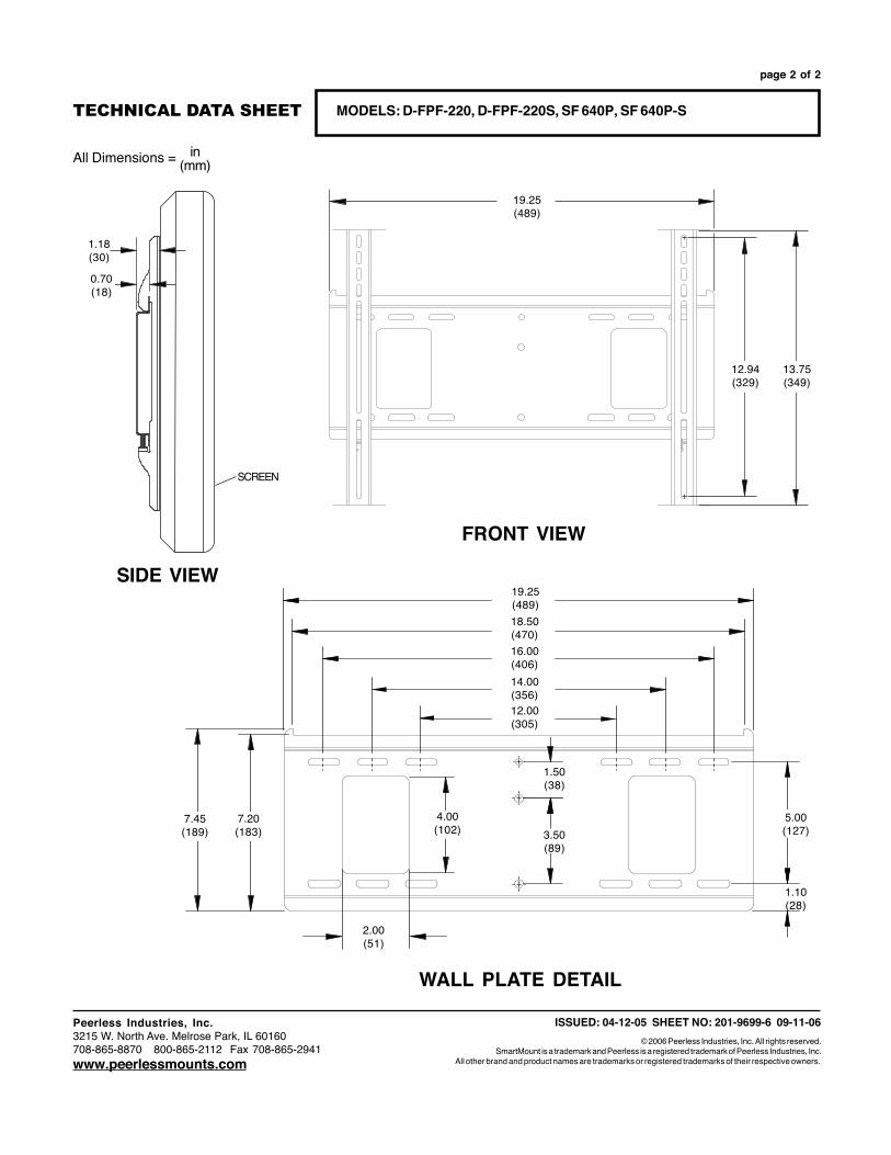
!"#$%&#'()*'!')+$""!) ,#9=K568E7'J7E<'LE77'HD;9<'GD6',,R'*')2R'"?65598
"N=BB=9F'PE6<D9':=C598=D98&
I d ":';$%FC%Z$";%JJ[
L d #:'::%FC%Z"$A%JJ[
. d #';$%FC%ZAA%JJ[
!"#$%&#'()*'!')+$""! !"#$%&'(#)*+*),,-.(#)*+*),,-&.(&*(/0-+.(&*(/0-+)&
1234(,(56(,
7&&8$#'(-0)9,)-:((&;$$<(="'(,-9)>/>>)/((->)99)-/+44?@4AA( 7BCDAE?F4A.( 7BGH!"#$%&'%()*+,%-./'%0/1*)2/%34*56%78%9:#9:
;:<=<9$=<<;:%%%<::=<9$="##"%%>4?%;:<=<9$="@A#
IIIH144?@4AAJ5DBEAHG5J
B%"::9%3//*1/22%7CDE2+*F/26%7CG'%-11%*FH,+2%*/2/*./D'
IJ4*+0)EC+%F2%4%+*4D/J4*5%4CD%3//*1/22%F2%4%*/HF2+/*/D%+*4D/J4*5%)K%3//*1/22%7CDE2+*F/26%7CG'
-11%)+,/*%L*4CD%4CD%M*)DEG+%C4J/2%4*/%+*4D/J4*52%)*%*/HF2+/*/D%+*4D/J4*52%)K%+,/F*%*/2M/G+F./%)NC/*2'
:';:
O#<P
#'#<
O!:P
&7#$(K7$L
IQRSS(
-11%TFJ/C2F)C2%U FCOJJP
*M"=<(K7$L
#@'"$
OA<@P
#!';$
O!A@P
#"'@A
O!"@P
#<'$:
OA;:P
LN%%(+%N<$(#$<N7%
#@'"$
OA<@P
#9'::
OA:9P
#A'::
O!$9P
#"'::
O!:$P
#'$:
O!<P
!'$:
O<@P
$'::
O#";P
A'::
O#:"P;'":
O#<!P
#'#:
O"<P
;'A$
O#<@P
"'::
O$#P

3215 W. North Ave. • Melrose Park, IL 60160 • (800) 729-0307 or (708) 865-8870 • Fax: (708) 865-2941 • www.peerlessmounts.com
ISSUED: 01-06-06 SHEET #: 202-9080-2 01-26-06
Installation and Assembly:
Universal Flat Wall Mount
Features:• For flat panel screens
• Ultra-slim design holds the screen flat against the wall
• Screen simply hooks onto the wall plate for quick and easy installation
• Includes hardware for installation to wood studs, concrete, and cinder block
Model #
D-FPF-220, D-FPF-220S,
SF 640, SF 640-S, SF 640P,
SF 640P-S, RTFPF-220,
RTFPF-220S
D-FPF-320, D-FPF-320S,
SF 660, SF 660-S, SF 660P,
SF 660P-S, RTFPF-320,
RTFPF-320S
SF 670, SF 670-S, SF 670P,
SF 670P-S
SF 680, SF 680-S, SF 680P,
SF 680P-S350 lb (159 kg)
Max UL Load Capacity
150 lb (68 kg)
200 lb (91 kg)
250 lb (113 kg)
32"-60"
42"-71"
61"-102"
Product is UL rated for screen size range and load
capacity per chart below
Screen Size Range
23"-46"
�

2 of 24 ISSUED: 01-06-06 SHEET #: 202-9080-2 01-26-06
Note: Read entire instruction sheet before you start installation and assembly.
Tools Needed for Assembly• stud finder ("edge to edge" stud finder is recommended)
• phillips screwdriver
• drill
• 1/4" bit for concrete and cinder block wall
• 1/2" bit for metal stud wall
• 5/32" bit for metal or wood stud wall
• level
Table of Contents
Parts List .............................................................................................................................................................................. 3
Installation to Double Wood Stud Wall .................................................................................................................................. 4
Installation to Triple Wood Stud Wall .................................................................................................................................... 5
Installation to Solid Concrete or Cinder Block ....................................................................................................................... 6
Installing Adapter Brackets ................................................................................................................................................... 7
Installing Flat Panel Screen to Wall Plate ............................................................................................................................. 8
For customer care call (800) 729-0307 or (708) 865-8870.
• Do not begin to install your Peerless product until you have read and understood the instructions and warnings
contained in this Installation Sheet. If you have any questions regarding any of the instructions or warnings, please
call Peerless customer care at 1-800-729-0307.
• This product should only be installed by someone of good mechanical aptitude, has experience with basic building
construction, and fully understands these instructions.
• Make sure that the supporting surface will safely support the combined load of the equipment and all attached hard-
ware and components.
• Never exceed the Maximum UL Load Capacity. See page one.
• If mounting to wood wall studs, make sure that mounting screws are anchored into the center of the studs. Use of an
"edge to edge" stud finder is highly recommended.
• Always use an assistant or mechanical lifting equipment to safely lift and position equipment.
• Tighten screws firmly, but do not overtighten. Overtightening can damage the items, greatly reducing their holding
power.
WARNING
Accessories• 4 piece Metal Stud Fastener Kit (ACC 415) (Metal Stud not evaluated by UL)
• 2 piece Metal Stud Fastener Kit (ACC 215) (Metal Stud not evaluated by UL)

3 of 24 ISSUED: 01-06-06 SHEET #: 202-9080-2 01-26-06
DD
EE
AA
CCBBFF
Adapter Bracket Fasteners
D-F
PF
-220, D
-FP
F-2
20S
,
SF
640, S
F 6
40-S
,
SF
640P, S
F 6
40P
-S,
RT
FP
F-2
20, R
TF
PF
-220S
D-F
PF
-320, D
-FP
F-3
20S
,
SF
660, S
F 6
60-S
,
SF
660P, S
F 6
60P
-S,
RT
FP
F-3
20, R
TF
PF
-320S
SF
670, S
F 6
70-S
,
SF
670P, S
F 6
70P
-S
SF
680, S
F 6
80-S
,
SF
680P, S
F 6
80P
-S
Parts List Non-Security SecurityBlack Silver Black Silver
Description Qty. Part Number Part Number Part Number Part Number! AA wall plate (double stud) 1 200-1797 200-4797 200-1797 200-4797
! (double stud) 201-1018 201-4018 201-1018 201-4018! (triple stud) 200-1901 200-4901 200-1901 200-4901
! (triple stud) 200-1902 200-4902 200-1902 200-4902! BB adapter bracket 2 200-0758 200-0759 200-0760 200-0761
! 200-0754 200-0755 200-0756 200-0757! 200-0940 200-0941 200-0942 200-0943
! 200-0944 200-0945 200-0946 200-0947! CC deep adapter bracket 2 200-0750 200-0751 200-0752 200-0753
! ! DD #14 x 2.5 wood screw 4 5S1-015-C03 5S1-015-C03 5S1-015-C03 5S1-015-C03! ! 6 5S1-015-C03 5S1-015-C03 5S1-015-C03 5S1-015-C03
! ! EE Alligator® anchor 4 590-0097 590-0097 590-0097 590-0097! ! 6 590-0097 590-0097 590-0097 590-0097
! FF 4 mm allen wrench 1 560-1131 560-1131 560-1131 560-1131! ! ! 1 560-1146 560-1146 560-1146 560-1146
M4 x 12 mm (6)
M4 x 25 mm (4)
M5 x 12 mm (4)
M5 x 25 mm (4)
M8 x 16 mm (6) M8 x 40 mm (6)M8 x 25 mm (4) I.D. .34" (4)M10 x 15 mm (4)
I.D. .22" (4)
M6 x 30 mm (4)
M6 x 12 mm (4)
M6 x 25 mm (4)
M6 x 20 mm (4)
multi-washer (6)
I.D. .35" (6)
Before you begin, make sure all parts shown are included with your product.
Parts may appear slightly different than illustrated.
Note: The sorted-for-you™ fastener pack included was made specifically for your product and may not contain all componentsshown below.

4 of 24 ISSUED: 01-06-06 SHEET #: 202-9080-2 01-26-06
Installation to Double Wood Stud Wall
1
Note: If mounting equipment weighing greater than 200 lbs, triple stud mounting is strongly recommended.
Skip to page 5.
Wall plate (AA) can be mounted to two studs that are 16" apart. Use a stud finder to locate the edges of the studs.
Use of an edge-to-edge stud finder is highly recommended. Based on their edges, draw a vertical line down each
stud’s center. Place wall plate on wall as a template. The top mounting slots should be located above the desired
screen center as indicated by dimension X in figure 1.1 and chart below. Level plate, and mark the center of the four
mounting holes. Make sure that the mounting holes are on the stud centerlines. Drill four 5/32" (4 mm) dia. holes 2-
1/2" (65 mm) deep. Make sure that the wall plate is level, secure it using four #14 x 2.5" wood screws (DD) as shown
in figure 1.2.
Note: Wall plate may be mounted up to 4" (102 mm) off center as shown in figure 1.1.
Skip to step 2 on page 7.
• Installer must verify that the supporting surface will safely support the combined load of the equipment and all attached
hardware and components.
• Tighten wood screws so that wall plate is firmly attached, but do not overtighten. Overtightening can damage the
screws, greatly reducing their holding power.
• Never tighten in excess of 80 in. • lb (9 N.M.).
• Make sure that mounting screws are anchored into the center of the stud. The use of an "edge to edge" stud finder is
highly recommended.
• Hardware provided is for attachment of mount through standard thickness drywall or plaster into wood studs. Installers
are responsible to provide hardware for other types of mounting situations.
WARNING
fig. 1.1
4"
(102 mm)
CS
4"
(102 mm)
DDAA
fig. 1.2
CS = center of screen
AA
X
Model #
SF 640, SF 640-S, SF 640P,
SF 640P-S, RTFPF-220,
RTFPF-220S
SF 660, SF 660-S, SF 660P,
SF 660P-S, RTFPF-320,
RTFPF-320S
4-5/8" (117 mm)
X Dimension
2.5" (64 mm)
STUD

6 of 24 ISSUED: 01-06-06 SHEET #: 202-9080-2 01-26-06
Installation to Solid Concrete or Cinder Block
1Make sure that wall plate (AA) is level, use it as a
template to mark four mounting holes. The top
mounting slots should be located above the desired
screen center as indicated by dimension X in figure
1.1 and charts on pages 4 and 5. Drill four 1/4" (6 mm)
dia. holes to a minimum depth of 2.5" (64 mm). Insert
anchors (EE) in holes flush with wall as shown (right).
Place wall plate over anchors and secure with #14 x
2.5" screws (DD). Level, then tighten all fasteners.
Note: Six holes and six sets of fasteners are required
when mounting the wall plate for equipment weighing
greater than 200 lbs.
• When installing Peerless wall mounts on cinder block, verify that you have a minimum of 1-3/8" of actual concrete
thickness in the hole to be used for the concrete anchors. Do not drill into mortar joints! Be sure to mount in a solid
part of the block, generally 1" minimum from the side of the block. Cinder block must meet ASTM C-90 specifica-
tions. It is suggested that a standard electric drill on slow setting is used to drill the hole instead of a hammer drill to
avoid breaking out the back of the hole when entering a void or cavity.
• Concrete must be 2000 psi density minimum. Lighter density concrete may not hold concrete anchor.
• Installer must verify that the supporting surface will safely support the combined load of the equipment and all attached
hardware and components.
WARNING
CU
TA
WA
Y V
IEW
INCORRECT
concrete
surface1
3
2
EE
Drill holes and insert anchors (EE).
CORRECT
Place plate (AA) over anchors (EE) and secure with screws (DD).
Tighten all fasteners.
wallplate
plaster/
dry wall
concrete wall plate concrete
plaster/
dry wall
• Always attach concrete anchors directly to load-bearing concrete.
• Never attach concrete anchors to concrete coveredwith plaster, drywall, or other finishing material. Ifmounting to concrete surfaces covered with a finishingsurface is unavoidable, the finishing surface must be
counterbored as shown below. Be sure concrete
anchors do not pull away from concrete when tighten-
ing screws. If plaster/drywall is thicker than 5/8",custom fasteners must be supplied by installer.
WARNING
AA
• Tighten screws so that wall plate is firmly attached,but do not overtighten. Overtightening can damagescrews, greatly reducing their holding power.
• Never tighten in excess of 80 in. • lb (9 N.M.).
WARNING
DD
AA
EEDD
EE
solid concrete
cinder block
8 of 24 ISSUED: 01-06-06 SHEET #: 202-9080-2 01-26-06
© 2006 Peerless Industries, Inc. All rights reserved.
Peerless is a registered trademark of Peerless Industries, Inc.
All other brand and product names are trademarks or registered trademarks of their respective owners.
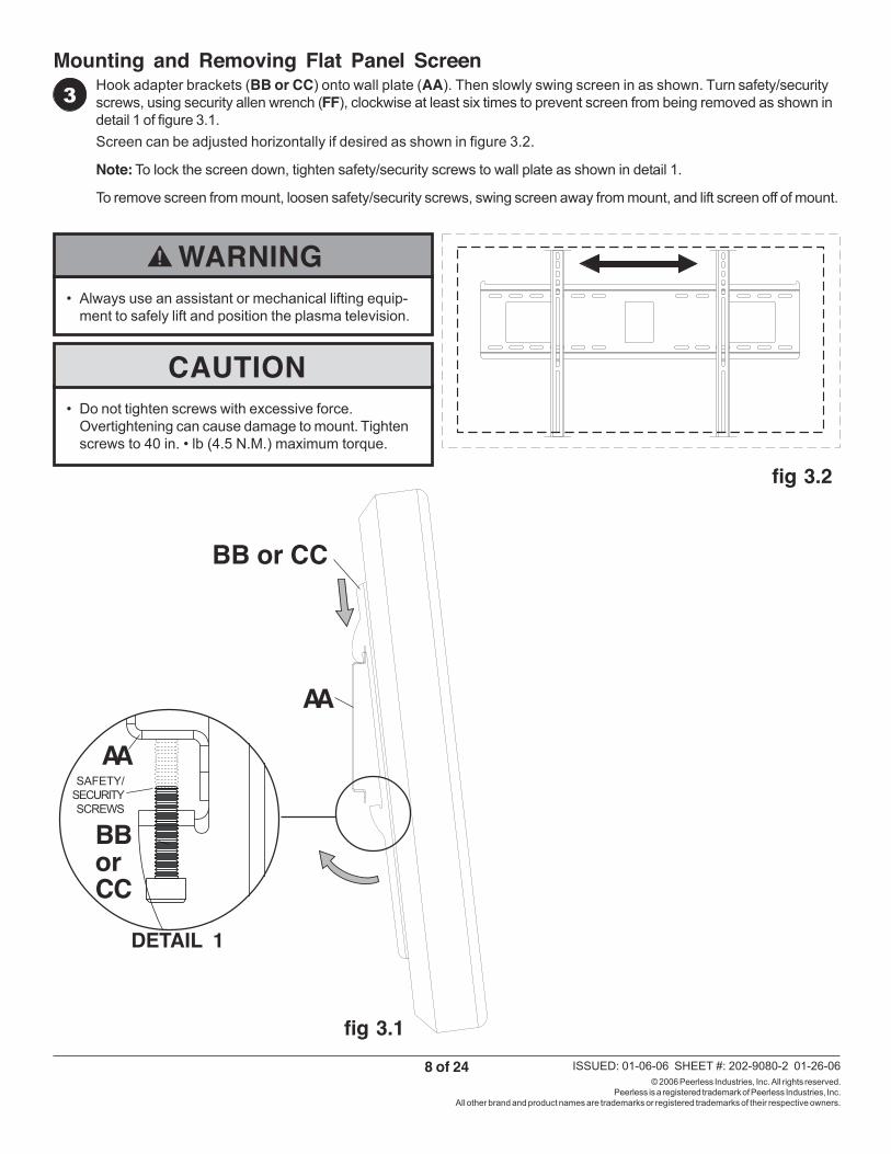
Mounting and Removing Flat Panel ScreenHook adapter brackets (BB or CC) onto wall plate (AA). Then slowly swing screen in as shown. Turn safety/security
screws, using security allen wrench (FF), clockwise at least six times to prevent screen from being removed as shown in
detail 1 of figure 3.1.
Screen can be adjusted horizontally if desired as shown in figure 3.2.
Note: To lock the screen down, tighten safety/security screws to wall plate as shown in detail 1.
To remove screen from mount, loosen safety/security screws, swing screen away from mount, and lift screen off of mount.
3
• Always use an assistant or mechanical lifting equip-
ment to safely lift and position the plasma television.
WARNING
AA
BB or CC
DETAIL 1
BBorCC
SAFETY/
SECURITY
SCREWS
AA
• Do not tighten screws with excessive force.
Overtightening can cause damage to mount. Tighten
screws to 40 in. • lb (4.5 N.M.) maximum torque.
CAUTION
fig 3.1
fig 3.2

3215 W. North Ave. • Melrose Park, IL 60160 • (800) 729-0307 or (708) 865-8870 • Fax: (708) 865-2941 • www.peerlessmounts.com
ISSUED: 01-06-06 SHEET #: 202-9080-2 01-26-06
Instalación y montaje:
Soporte universal plano de pared
Características:
• Para pantallas planas
• El diseño ultra delgado sujeta la pantalla plana contra la
pared
• La pantalla simplemente se engancha en la placa de
apoyo para una instalación rápida y fácil
• Incluye los herrajes para instalación en montantes de
madera, concreto y bloques de hormigón de escorias
Nº de modelo
D-FPF-220, D-FPF-220S,
SF 640, SF 640-S, SF 640P,
SF 640P-S, RTFPF-220,
RTFPF-220S
D-FPF-320, D-FPF-320S,
SF 660, SF 660-S, SF 660P,
SF 660P-S, RTFPF-320,
RTFPF-320S
SF 670, SF 670-S, SF 670P,
SF 670P-S
SF 680, SF 680-S, SF 680P,
SF 680P-S
Este producto está clasificado por Underwriters Laboratories (UL) para utilizarse con
pantallas dentro de las gamas de tamaños y de la capacidad de soportar carga ____
según lo indicado en la tabla que aparece continuación.
32"-60"
42"-71"
61"-102"
Gama de tamaños
de la pantalla
23"-46"
350 lb (159 kg)
Capacidad máxima de
soportar carga según UL:
150 lb (68 kg)
200 lb (91 kg)
250 lb (113 kg)
�

10 of 24 ISSUED: 01-06-06 SHEET #: 202-9080-2 01-26-06
Nota: Lea toda la hoja de instrucciones antes de iniciar la instalación y el montaje.
Contenido
Lista de piezas ................................................................................................................................................................... 11
Instalación en una pared con montantes de madera dobles ................................................................................................ 12
Instalación en una pared con montantes de madera triples ................................................................................................ 13
Instalación en una pared de concreto macizo o de bloques de hormigón de escorias ........................................................ 14
Instalación de los soportes adaptadores ............................................................................................................................. 15
Instalación de la pantalla plana en la placa de apoyo ......................................................................................................... 16
Para atención al cliente, llame al (800) 729-0307 ó (708) 865-8870.
Accesorios• Juego de 4 piezas de fijaciones para montantes de metal (ACC 415) (montante de metal no evaluado por UL)
• Juego de 2 piezas de fijaciones para montantes de metal (ACC 215) (montante de metal no evaluado por UL)
• No comience la instalación de su producto Peerless sin antes leer y comprender las instrucciones y los avisos de
precaución contenidos en esta hoja de instalación. Ante cualquier duda respecto a las instrucciones o avisos de
precaución, llame al departamento de servicio al cliente de Peerless al 1-800-729-0307.
• Este producto debe instalarlo una persona con buenas aptitudes mecánicas, experiencia en la construcción básica
de edificios y una comprensión total de estas instrucciones.
• Asegúrese de que la superficie de apoyo sea capaz de soportar firmemente la carga combinada del equipo y todos
los herrajes y componentes.
• Nunca sobrepase la capacidad máxima de soportar carga aceptada por Underwriters Laboratories. Vea la página
uno.
• Si la instalación va a hacerla en paredes con montantes de madera, asegúrese de que los tornillos de montaje estén
anclados en el centro de los montantes. Se recomienda usar un localizador de montantes de “borde a borde”.
• Siempre solicite la ayuda de un asistente o utilice un equipo de izar mecánico para levantar y colocar el equipo con
más seguridad.
• Apriete los tornillos firmemente, pero no en exceso. El apriete excesivo puede dañar los artículos, reduciendo
enormemente su fuerza de fijación.
ADVERTENCIA
Herramientas necesarias para el montaje• localizador de montantes (se recomienda usar el de “borde a borde”)
• destornillador phillips
• taladro
• broca de 1/4" para pared de concreto y de bloques de hormigón de escorias
• broca de 1/2" para pared con montantes de metal
• broca de 5/32" para pared con montantes de metal o madera
• nivel
11 of 24 ISSUED: 01-06-06 SHEET #: 202-9080-2 01-26-06
DD
EE
AA
CCBBFF
Fijaciones para los soportes adaptadores
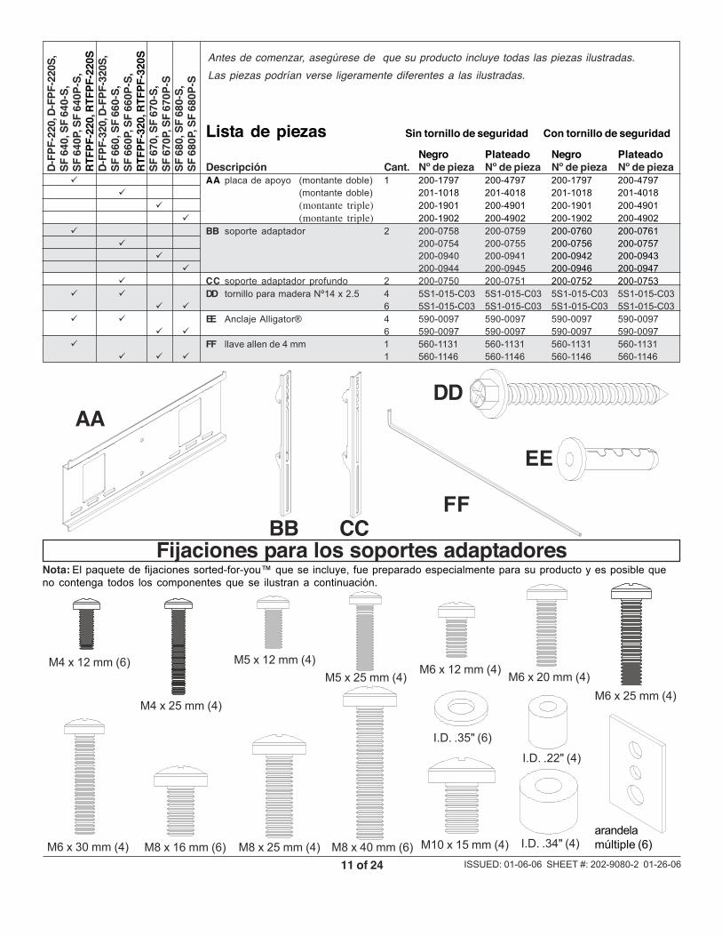
Lista de piezas Sin tornillo de seguridad Con tornillo de seguridad
Negro Plateado Negro PlateadoDescripción Cant. Nº de pieza Nº de pieza Nº de pieza Nº de pieza
! AA placa de apoyo (montante doble) 1 200-1797 200-4797 200-1797 200-4797
! (montante doble) 201-1018 201-4018 201-1018 201-4018
! (montante triple) 200-1901 200-4901 200-1901 200-4901
! (montante triple) 200-1902 200-4902 200-1902 200-4902
! BB soporte adaptador 2 200-0758 200-0759 200-0760 200-0761
! 200-0754 200-0755 200-0756 200-0757
! 200-0940 200-0941 200-0942 200-0943
! 200-0944 200-0945 200-0946 200-0947
! CC soporte adaptador profundo 2 200-0750 200-0751 200-0752 200-0753
! ! DD tornillo para madera Nº14 x 2.5 4 5S1-015-C03 5S1-015-C03 5S1-015-C03 5S1-015-C03
! ! 6 5S1-015-C03 5S1-015-C03 5S1-015-C03 5S1-015-C03
! ! EE Anclaje Alligator® 4 590-0097 590-0097 590-0097 590-0097
! ! 6 590-0097 590-0097 590-0097 590-0097
! FF llave allen de 4 mm 1 560-1131 560-1131 560-1131 560-1131
! ! ! 1 560-1146 560-1146 560-1146 560-1146
M4 x 12 mm (6)
M4 x 25 mm (4)
M5 x 12 mm (4)
M5 x 25 mm (4)
M8 x 16 mm (6) M8 x 40 mm (6)M8 x 25 mm (4) I.D. .34" (4)M10 x 15 mm (4)
I.D. .22" (4)
M6 x 30 mm (4)
M6 x 12 mm (4)
M6 x 25 mm (4)
M6 x 20 mm (4)
I.D. .35" (6)
Antes de comenzar, asegúrese de que su producto incluye todas las piezas ilustradas.
Las piezas podrían verse ligeramente diferentes a las ilustradas.
Nota: El paquete de fijaciones sorted-for-you™ que se incluye, fue preparado especialmente para su producto y es posible que
no contenga todos los componentes que se ilustran a continuación.
arandela
múltiple (6)
D-F
PF
-220, D
-FP
F-2
20S
,S
F 6
40, S
F 6
40-S
,S
F 6
40P, S
F 6
40P
-S,
RT
FP
F-2
20, R
TF
PF
-220S
D-F
PF
-320, D
-FP
F-3
20S
,S
F 6
60, S
F 6
60-S
,S
F 6
60P, S
F 6
60P
-S,
RT
FP
F-3
20, R
TF
PF
-320S
SF
670, S
F 6
70-S
,S
F 6
70P, S
F 6
70P
-SS
F 6
80, S
F 6
80-S
,S
F 6
80P, S
F 6
80P
-S

12 of 24 ISSUED: 01-06-06 SHEET #: 202-9080-2 01-26-06
Instalación en una pared con montantes de madera dobles
1
• El instalador debe verificar que la superficie de apoyo sea capaz de soportar firmemente la carga combinada del
equipo y todos los herrajes y componentes.
• Apriete los tornillos para madera de tal modo que la placa de apoyo quede firmemente sujeta, pero no apriete en
exceso. El apriete excesivo puede dañar los tornillos, reduciendo enormemente su fuerza de fijación.
• Nunca apriete más de 80 pulg-lb (9 N•m).
• Asegúrese de que los tornillos de montaje queden bien fijos en el centro del montante. Se recomienda usar un
localizador de montantes de “borde a borde”.
• Los herrajes suministrados son para fijar el soporte a través de tabique de yeso-cartón o yeso de espesor estándar a
los montantes de madera. Los instaladores son responsables de suministrar los herrajes para otros tipos de
situaciones de montaje.
ADVERTENCIA
fig. 1.1
4"
(102 mm)
CS
4"
(102 mm)
DDAA
fig. 1.2
CS = centro de la pantalla
AA
X
Nº de modelo
SF 640, SF 640-S, SF 640P,
SF 640P-S, RTFPF-220,
RTFPF-220S
SF 660, SF 660-S, SF 660P,
SF 660P-S, RTFPF-320,
RTFPF-320S
4-5/8" (117 mm)
Dimensión X
2.5" (64 mm)
MONTANTE
Nota: Si el peso del equipo de montaje es mayor que 200 lbs, se recomienda utilizar montantes triples.
Pase a la página 13.
La placa de apoyo (AA) puede fijarse a dos montantes con una separación de 16" entre ellos. Utilice un localizador
de montantes para ubicar los bordes de los montantes. Se recomienda usar un localizador de montantes de “borde a
borde”. Basado en sus bordes, trace una línea vertical por el centro de cada montante.
Coloque la placa de apoyo en
la pared para usarla como plantilla. Las ranuras de montaje superiores deben quedar ubicadas más arriba del centro
de la pantalla, como lo indica la dimensión X en la figura 1.1 y la tabla que aparece a continuación. Nivele la placa y
marque el centro de los cuatro agujeros. Asegúrese de que los agujeros de montaje se encuentren en la línea central
de los montantes. Taladre cuatro agujeros de 5/32" (4 mm) de diámetro y 2-1/2" (65 mm) de profundidad.
Asegúrese
de que la placa de apoyo esté nivelada, fíjela con los cuatro tornillos para madera N° 14 x 2.5" (DD), como se
muestra en la figura 1.2.
Nota: La placa de apoyo puede instalarse hasta 4" (102 mm) desplazada del centro, como se muestra en la figura
1.1.
Proceda al paso 2 en la página 15.

14 of 24 ISSUED: 01-06-06 SHEET #: 202-9080-2 01-26-06
Instalación en una pared de concreto macizo o de bloques de hormigón de escorias
1Asegúrese de que la placa de apoyo (AA) esté
nivelada, utilícela como una plantilla para marcar los
cuatro agujeros de montaje. El agujero de montaje
superior debe estar ubicado más arriba del centro de
la pantalla deseado, como lo indica la dimensión Xen la figura 1.1 y las tablas en las páginas 4 y 5.
Taladre cuatro agujeros de 1/4" (6 mm) de diámetro
hasta una profundidad mínima de 2.5" (64 mm).
Inserte los anclajes (EE) en los agujeros a ras con la
pared, como se muestra (a la derecha). Coloque la
placa de apoyo sobre los anclajes y fíjela con los
tornillos N°14 x 2.5" (DD). Nivele y después apriete
todas las fijaciones.
Nota: Se necesitan seis agujeros y seis juegos de
fijaciones cuando se instala la placa de apoyo para
un equipo cuyo peso es mayor que 200 lbs.
• Cuando instale soportes de pared Peerless en bloques de hormigón de escorias, verifique que tengan un mínimo de
1-3/8" de superficie efectiva de concreto en el agujero que va a utilizar para los anclajes de concreto. ¡No perfore en
las juntas de mortero! Asegúrese de instalar el soporte en una parte sólida del bloque, generalmente a un mínimo de
1" del costado del bloque. El bloque de hormigón de escorias debe ser de conformidad con las especificaciones C-
90 de ASTM. Se sugiere taladrar el agujero con un taladro eléctrico normal en velocidad lenta en vez de un taladro
percutor para evitar romper la parte trasera del agujero al entrar en un espacio o cavidad.
• El concreto debe tener una densidad mínima de 2000 psi. Un concreto menos denso podría no ser capaz de sujetar
el anclaje para concreto.
• El instalador debe verificar que la superficie de apoyo sea capaz de soportar firmemente la carga combinada del
equipo y todos los herrajes y componentes.
ADVERTENCIA
• Siempre fije los anclajes de expansión directamente
al concreto que soporta carga.
• Nunca fije los anclajes de expansión a una pared de
concreto recubierta con yeso, tabiques de yeso-
cartón u otro material de acabado. Si el montaje a
superficies de concreto recubiertas con una
superficie de acabado es inevitable, será necesario
escariar el acabado, como se muestra más abajo.
Asegúrese de que los anclajes de concreto no se
alejen del concreto al apretar los tornillos. Si el
grosor de la pared de yeso/tabique de yeso-cartón es
mayor que 5/8", el instalador deberá suministrar
fijaciones especiales.
ADVERTENCIA
• Apriete los tornillos de tal modo que la placa de
apoyo quede firmemente sujeta, pero no los apriete
en exceso. El apriete excesivo puede dañar los
tornillos, reduciendo enormemente su fuerza de
fijación.
• Nunca apriete más de 80 pulg-lb (9 N•m).
ADVERTENCIA
VISTA EN CORTE
INCORRECTO
superficie de
concreto1
3
2
EEPerfore los agujeros y después inserte los anclajes (EE).
Coloque la placa (AA) sobre los anclajes (EE) y fíjela con
los tornillos (DD).
Apriete todas las fijaciones
AA
EEDD
DD
AA EE
concreto macizo
bloque dehormigón de
escorias
placa de
apoyo
yeso/tabique
yeso-cartón
concreto
placa de
apoyo
yeso/tabique
yeso-cartón
CORRECTO
concreto

16 of 24 ISSUED: 01-06-06 SHEET #: 202-9080-2 01-26-06
AA
BB o CC
DETAIL 1
BBoCC
TORNILLOS
DE
SEGURIDAD
AA
fig 3.1
© 2006 Peerless Industries, Inc. All rights reserved.
Peerless is a registered trademark of Peerless Industries, Inc.
All other brand and product names are trademarks or registered trademarks of their respective owners.
Montaje y desmontaje de la pantalla planaEnganche los soportes adaptadores (BB o CC) en la placa de apoyo (AA).
Después gire lentamente la pantalla
hacia dentro, como se muestra. Con la ayuda de la llave allen (FF), gire los tornillos de seguridad en sentido horario, por
lo menos seis veces, para evitar el desmontaje de la pantalla, como se muestra en el detalle 1 de la figura 3.1.
Si lo desea, la pantalla puede ajustarse en sentido horizontal, como se muestra en la figura 3.2.
Nota: Para trabar la pantalla , apriete los tornillos de seguridad a la placa de apoyo, como se muestra en el detalle 1.
Para desmontar la pantalla, afloje los tornillos de seguridad, gire la pantalla alejándola del soporte y levántela para
desmontarla.
3
• Siempre solicite la ayuda de un asistente o utilice un
equipo de izar mecánico para levantar y colocar el
televisor de plasma con más seguridad.
ADVERTENCIA
• No apriete los tornillos aplicando demasiada fuerza.
El apriete excesivo podría dañar el soporte. Apriete
los tornillos a 40 pulg-lb (4.5 N•m) de par torsor
máximo.
ATENCIÓN
fig 3.2

3215 W. North Ave. • Melrose Park, IL 60160 • (800) 729-0307 or (708) 865-8870 • Fax: (708) 865-2941 • www.peerlessmounts.com
ISSUED: 01-06-06 SHEET #: 202-9080-2 01-26-06
Installation et assemblage :
Monture murale universelle pour écrans plats
Caractéristiques:
• Pour les écrans plats
• Conception ultra-mince permettant de maintenir l’écran à
plat contre le mur
• L’écran s’accroche simplement sur la plaque murale, ce qui
facilite son installation rapide
• Inclut la visserie pour l’installation sur montants en bois,
béton et blocs de béton de mâchefer (OU parpaings)
Modèle nº
D-FPF-220, D-FPF-220S,
SF 640, SF 640-S, SF 640P,
SF 640P-S, RTFPF-220,
RTFPF-220S
D-FPF-320, D-FPF-320S,
SF 660, SF 660-S, SF 660P,
SF 660P-S, RTFPF-320,
RTFPF-320S
SF 670, SF 670-S, SF 670P,
SF 670P-S
SF 680, SF 680-S, SF 680P,
SF 680P-S
Ce produit est évalué par l’Underwriter’s Laboratory (UL) pour la plage de dimensions
d’écrans et la capacité de charge de______indiquées dans le tableau ci-dessous
32"-60"
42"-71"
61"-102"
Plage de
dimensions
d’écrans
23"-46"
350 lb (159 kg)
Capacité de charge
maximale établie par l’UL :
150 lb (68 kg)
200 lb (91 kg)
250 lb (113 kg)
�

18 of 24 ISSUED: 01-06-06 SHEET #: 202-9080-2 01-26-06
Remarque : Lisez entièrement la fiche d’instructions avant de commencer l’installation et l’assemblage.
Outils nécessaires pour l’assemblage• localisateur de montants (le localisateur de montants « bord à bord » est recommandé)
• tournevis cruciforme
• perceuse
• mèche de 0,62 cm (1/4 po) pour les murs en béton et les blocs de béton de mâchefer
• mèche de 1,25 cm (1/2 po) pour les murs à montants métalliques
• mèche de 0,4 cm (5/32 po) pour les murs à montants métalliques ou à montants en bois
• niveau
Table des matières
Liste des pièces ................................................................................................................................................................. 19
Installation sur un mur à doubles montants en bois ............................................................................................................ 20
Installation sur un mur à triples montants en bois ............................................................................................................... 21
Installation sur du béton plein ou un bloc de béton de mâchefer ......................................................................................... 22
Installation de supports adaptateurs ................................................................................................................................... 23
Installation de l’écran plat sur la plaque murale................................................................................................................... 24
Pour le service à la clientèle, appelez le 800 729-0307 ou le (708) 865-8870.
• Ne commencez pas à installer votre produit Peerless avant d’avoir lu et assimilé les instructions et les mises en
garde contenues dans cette fiche d’installation. Pour toute question concernant les instructions ou les mises en
garde, appelez le service à la clientèle de Peerless au 1-800 729-0307.
• Ce produit ne doit être installé que par une personne ayant de bonnes aptitudes en mécanique, expérimentée en
travaux de construction de base, et démontrant une parfaite compréhension de ces instructions.
• Assurez-vous que la surface de support pourra soutenir sans danger la charge combinée de l’équipement, de toute
sa visserie et de tous ses composants.
• Ne dépassez jamais la capacité de charge maximum établie par l’UL. Reportez-vous à la page 1.
• Si vous effectuez le montage sur un mur à montants en bois, assurez-vous que les vis de montage sont ancrées au
centre des montants. L’usage d’un localisateur « bord à bord » est fortement conseillé.
• Pour lever et positionner l’équipement en toute sécurité, faites-vous toujours aider par une autre personne ou utilisez
un matériel de levage mécanique.
• Serrez fermement les vis, mais sans excès. Un serrage excessif peut endommager les éléments et en réduire
considérablement le pouvoir de maintien.
AVERTISSEMENT
Accessoires• Kit de 4 fixations pour montants métalliques (ACC 415) (Le montant métallique n’a pas été évalué par l’UL)
• Kit de 2 fixations pour montants métalliques (ACC 215) (Le montant métallique n’a pas été évalué par l’UL)
19 of 24 ISSUED: 01-06-06 SHEET #: 202-9080-2 01-26-06
DD
EE
AA
CCBB
FF
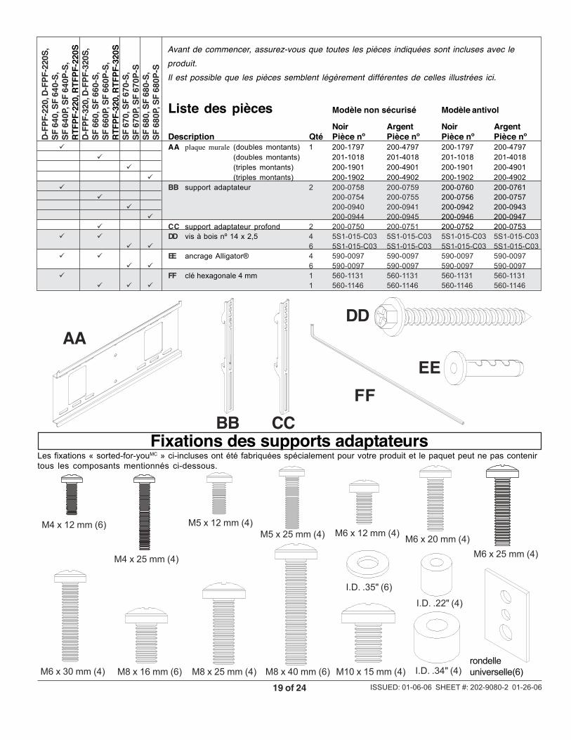
Fixations des supports adaptateurs
Liste des pièces Modèle non sécurisé Modèle antivol
Noir Argent Noir ArgentDescription Qté Pièce nº Pièce nº Pièce nº Pièce nº
! AA plaque murale (doubles montants) 1 200-1797 200-4797 200-1797 200-4797
! (doubles montants) 201-1018 201-4018 201-1018 201-4018
! (triples montants) 200-1901 200-4901 200-1901 200-4901
! (triples montants) 200-1902 200-4902 200-1902 200-4902
! BB support adaptateur 2 200-0758 200-0759 200-0760 200-0761
! 200-0754 200-0755 200-0756 200-0757
! 200-0940 200-0941 200-0942 200-0943
! 200-0944 200-0945 200-0946 200-0947
! CC support adaptateur profond 2 200-0750 200-0751 200-0752 200-0753
! ! DD vis à bois nº 14 x 2,5 4 5S1-015-C03 5S1-015-C03 5S1-015-C03 5S1-015-C03
! ! 6 5S1-015-C03 5S1-015-C03 5S1-015-C03 5S1-015-C03
! ! EE ancrage Alligator® 4 590-0097 590-0097 590-0097 590-0097
! ! 6 590-0097 590-0097 590-0097 590-0097
! FF clé hexagonale 4 mm 1 560-1131 560-1131 560-1131 560-1131
! ! ! 1 560-1146 560-1146 560-1146 560-1146
M4 x 12 mm (6)
M4 x 25 mm (4)
M5 x 12 mm (4)
M5 x 25 mm (4)
M8 x 16 mm (6) M8 x 40 mm (6)M8 x 25 mm (4) I.D. .34" (4)M10 x 15 mm (4)
I.D. .22" (4)
M6 x 30 mm (4)
M6 x 12 mm (4)
M6 x 25 mm (4)
M6 x 20 mm (4)
rondelle
universelle(6)
I.D. .35" (6)
Avant de commencer, assurez-vous que toutes les pièces indiquées sont incluses avec le
produit.
Il est possible que les pièces semblent légèrement différentes de celles illustrées ici.
Les fixations « sorted-for-youMC » ci-incluses ont été fabriquées spécialement pour votre produit et le paquet peut ne pas contenir
tous les composants mentionnés ci-dessous.
D-F
PF
-220, D
-FP
F-2
20S
,S
F 6
40, S
F 6
40-S
,S
F 6
40P, S
F 6
40P
-S,
RT
FP
F-2
20, R
TF
PF
-220S
D-F
PF
-320, D
-FP
F-3
20S
,S
F 6
60, S
F 6
60-S
,S
F 6
60P, S
F 6
60P
-S,
RT
FP
F-3
20, R
TF
PF
-320S
SF
670, S
F 6
70-S
,S
F 6
70P, S
F 6
70P
-SS
F 6
80, S
F 6
80-S
,S
F 6
80P, S
F 6
80P
-S

20 of 24 ISSUED: 01-06-06 SHEET #: 202-9080-2 01-26-06
Installation sur un mur à doubles montants en bois
1
Remarque : Si le matériel de montage pèse plus de 91 kg (200 lb), il est fortement conseillé d‘avoir recours au
montage à triples montants.
Passez à l’étape 21.
La plaque murale (AA) peut être montée sur deux montants espacés de 40 cm (16 po). Utilisez un localisateur de
montants pour repérer les bords des montants. L’usage d’un localisateur bord à bord est fortement conseillé. En
fonction de leurs bords, tracez une ligne verticale le long du centre de chaque montant. Utilisez la plaque murale
comme gabarit et placez-la sur le mur. Les fentes de montage supérieures doivent être situées au-dessus du centre
de l’écran, comme indiqué par la dimension X sur la figure 1.1 et le tableau ci-dessous. Mettez la plaque de niveau
et marquez le centre des quatre trous de montage. Assurez-vous que les trous de montage se trouvent sur les axes
des montants. Percez quatre trous de 0,4 cm (5/32 po) de diamètre et de 6,5 cm (2 1/2 po) de profondeur. Assurez-
vous que la plaque murale est de niveau, fixez-la à l’aide de quatre vis à bois nº 14 x 2,5 po (DD), comme illustré à la
figure 1.2.
Remarque : La plaque murale peut être décentrée d’un maximum de 10,2 cm (4 po), comme illustré à la figure 1.1.
Passez à l’étape 2, page 23.
• L’installateur doit s’assurer que la surface de support pourra soutenir sans danger la charge combinée de
l’équipement, de toute sa visserie et de tous ses composants.
• Serrez les vis à bois de manière que la plaque murale soit fermement fixée, mais sans excès. Un serrage excessif
peut endommager les vis et en réduire considérablement le pouvoir de maintien.
• Ne serrez jamais à plus de 9 Nm (80 po-lb).
• Assurez-vous que les vis de montage sont ancrées au centre des montants. L’usage d’un localisateur de montants «
bord à bord » est fortement conseillé.
• La visserie est fournie pour fixer la monture à travers une cloison sèche ou du plâtre d’épaisseur standard et dans
des montants en bois. Il appartient aux installateurs de fournir la visserie nécessaire pour d’autres types de situa-
tions.
AVERTISSEMENT
fig. 1.1
4"
(102 mm)
CE
4"
(102 mm)
DDAA
fig. 1.2
CE = centre de l’écran
AA
X
Modèle nº
SF 640, SF 640-S, SF 640P,
SF 640P-S, RTFPF-220,
RTFPF-220S
SF 660, SF 660-S, SF 660P,
SF 660P-S, RTFPF-320,
RTFPF-320S
4-5/8" (117 mm)
Dimension X
2.5" (64 mm)
MONTANT

22 of 24 ISSUED: 01-06-06 SHEET #: 202-9080-2 01-26-06
Installation sur du béton plein ou un bloc de béton de mâchefer
1Assurez-vous que la plaque murale (AA) est de niveau,
utilisez-la comme gabarit pour marquer les quatre
trous de montage. Les fentes de montage supérieures
doivent se trouver au-dessus du centre de l’écran,
comme illustré par la dimension X sur la figure 1.1 et
les tableaux des pages 4 et 5. Percez quatre trous de
0,6 cm (1/4 po) de diamètre à une profondeur
minimum de 6,4 cm (2,5 po). Insérez les ancrages
(EE) dans les trous au ras du mur, comme illustré (à
droite). Placez la plaque murale sur les ancrages et
fixez avec des vis nº 14 x 2,5 po (DD). Mettez-la de
niveau, puis serrez toutes les fixations.
Remarque : Pour un matériel pesant plus de 91 kg
(200 lb), le montage de la plaque murale exige six
trous et six jeux de fixations.
• Si vous installez des montures murales Peerless sur un bloc de béton de mâchefer, vérifiez que vous disposez d’une
épaisseur de béton d’au moins 3,4 cm (1 3/8 po) dans le trou destiné aux ancrages de béton. Ne percez pas dans
les joints de mortier ! Veillez à effectuer le montage dans une partie pleine du bloc, généralement à au moins 2,5 cm
(1 po) du côté du bloc. Le bloc de béton de mâchefer doit être conforme aux spécifications de l’ASTM C-90. Pour
percer le trou, il est conseillé d’utiliser une perceuse électrique standard sur un réglage bas au lieu d’un marteau
perforateur, afin d’éviter de briser la partie arrière du trou lorsque vous pénétrez un vide ou une cavité.
• Le béton doit avoir une densité minimum de 2 000 psi. Un béton de densité moindre risquerait de ne pas retenir un
ancrage de béton.
• Assurez-vous que la surface de support pourra soutenir sans danger la charge combinée de l’équipement, de toute
sa visserie et de tous ses composants.
AVERTISSEMENT
• Fixez toujours des ancrages de béton directement sur
du béton porteur.
• Ne fixez jamais d’ancrages sur du béton recouvert de
plâtre, une cloison sèche ou autre matériau de
finition. Si vous ne pouvez pas éviter d’effectuer le
montage sur une surface de finition, celle-ci doit être
chambrée, comme indiqué ci-dessous. Assurez-vous
que les ancrages de béton ne se séparent pas du
béton lorsque vous serrez les vis. Si l’épaisseur du
plâtre / de la cloison sèche dépasse 1,5 cm (5/8 po),
des fixations adaptées devront être fournies par
l’installateur.
AVERTISSEMENT
• Serrez les vis de manière que la plaque murale soit
fermement fixée, mais sans excès. Un serrage
excessif peut endommager les vis et en réduire
considérablement le pouvoir de maintien.
• Ne serrez jamais à plus de 9 Nm (80 po-lb).
AVERTISSEMENT
DD
AA EE
béton plein
bloc debéton demâchefer
VUE EN COUPE
INCORRECT
plaque
murale
plâtre/cloison
sèche
béton
CORRECT
plaque
murale
plâtre/cloison
sèche
béton
surface en
béton1
3
2
EEPercez des trous et insérez les ancrages (EE).
Placez la plaque (AA) sur les ancrages (EE) et fixez avec
des vis (DD).
Serrez toutes les fixations.
AA
EEDD
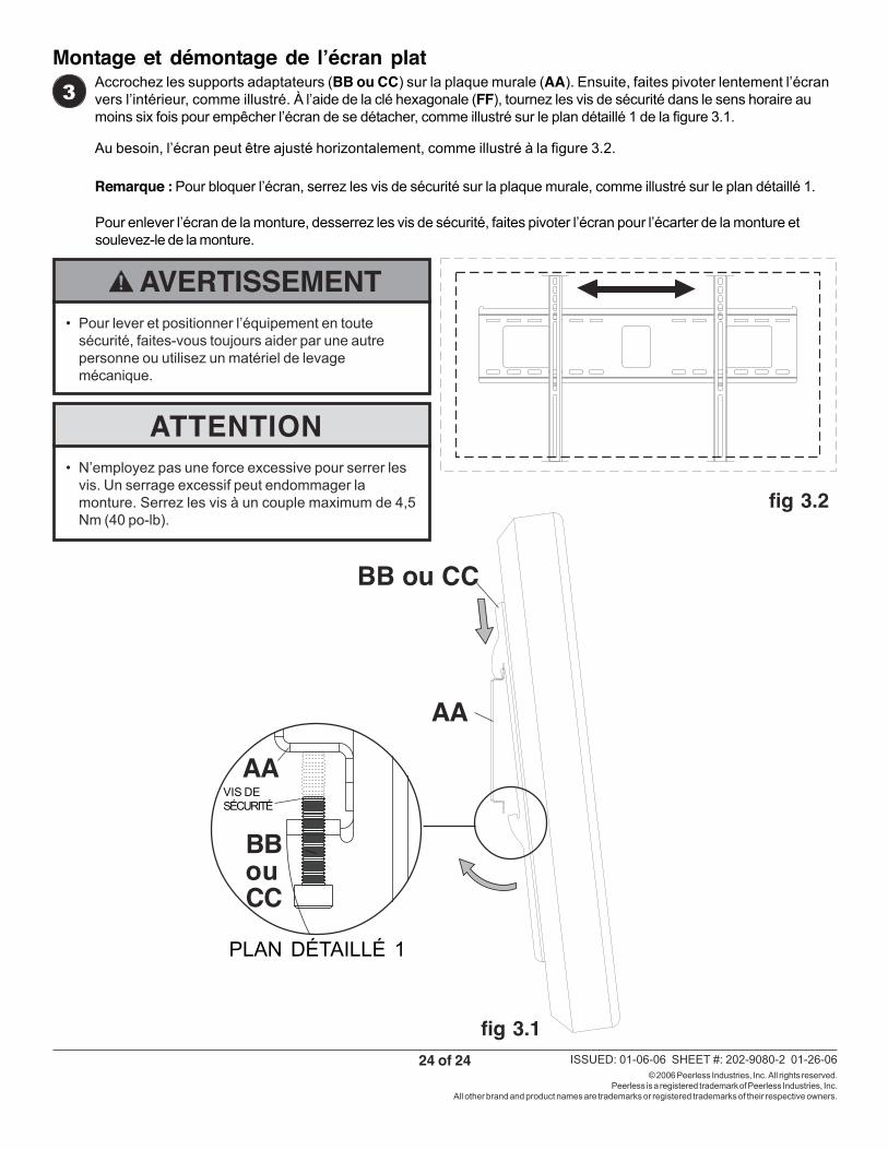
24 of 24 ISSUED: 01-06-06 SHEET #: 202-9080-2 01-26-06© 2006 Peerless Industries, Inc. All rights reserved.
Peerless is a registered trademark of Peerless Industries, Inc.All other brand and product names are trademarks or registered trademarks of their respective owners.
Montage et démontage de l’écran platAccrochez les supports adaptateurs (BB ou CC) sur la plaque murale (AA). Ensuite, faites pivoter lentement l’écranvers l’intérieur, comme illustré. À l’aide de la clé hexagonale (FF), tournez les vis de sécurité dans le sens horaire aumoins six fois pour empêcher l’écran de se détacher, comme illustré sur le plan détaillé 1 de la figure 3.1.
Au besoin, l’écran peut être ajusté horizontalement, comme illustré à la figure 3.2.
Remarque : Pour bloquer l’écran, serrez les vis de sécurité sur la plaque murale, comme illustré sur le plan détaillé 1.
Pour enlever l’écran de la monture, desserrez les vis de sécurité, faites pivoter l’écran pour l’écarter de la monture etsoulevez-le de la monture.
3
• Pour lever et positionner l’équipement en toutesécurité, faites-vous toujours aider par une autrepersonne ou utilisez un matériel de levagemécanique.
AVERTISSEMENT
• N’employez pas une force excessive pour serrer lesvis. Un serrage excessif peut endommager lamonture. Serrez les vis à un couple maximum de 4,5Nm (40 po-lb).
ATTENTION
fig 3.2
AA
BB ou CC
PLAN DÉTAILLÉ 1
BBouCC
VIS DESÉCURITÉ
AA
fig 3.1

Appendix 2 – Technical data sheet for AVT industrial camera

AVT Guppy F-033B / F-033C
The AVT Guppy camera family is distinguished byan IEEE 1394 interface and an extremely compactdesign. It consists of ten different camera variants(each available in b/w and color) and, with a widevariety of sensors and bandwidths, offers the rightsolution for nearly any conceivable application.The Guppy is available optionally in a casing orboard version (upon request) and therefore fits inthe smallest spaces. A selection of high-quality,sensitive sensors (CCD, CMOS) help the Guppy pro-vide outstanding image quality and true color.Four additional interlaced versions (EIA, CCIR)make it even more attractive to switch from analogto digital image processing. Due to its modularityand remarkable price/performance ratio, for manyapplications the Guppy is the ideal way to makethe move to digital image processing.
AVT Cameras
ALLIED VISION TECHNOLOGIES GMBHTaschenweg 2a | D-07646 Stadtroda | GermanyPhone: +49 (0)36428 6770 | Fax: +49 (0)36428 677-24www.alliedvisiontec.com | [email protected]
Guppy F-033B / F-033C
Small - easy - ingenious: Analog goes Guppy.
Highlights� IEEE 1394a� VGA (656 x 494)� Up to 58 fps (full resolution)� Progressive scan CCD, monochrome and color� True partical scan (higher frame rates by smaller
AOI)� Flexible AOI, flexible speed (full Format_7 support)� Asynchronous image trigger� Image preprocessing features:
- Auto controlled gain, exposure, white balance (separate reference AOI)
- Programmable LUT- And lots more ...
� Smart frame grabber features:- Single-shot, multi-shot, free-run- 1 prog. input / 3 prog. outputs- On-board RS-232 port- And lots more ...
� Industry proven and robust housing� C-Mount /CS-Mount (convertible via adapter)� OEM board level version, customized housings

AOI height / pixel Frame rate / fps
480 60
240 100
120 152
60 204
30 245
ALLIED VISION TECHNOLOGIES GMBHTaschenweg 2a | D-07646 Stadtroda | GermanyPhone: +49 (0)36428 6770 | Fax: +49 (0)36428 677-24www.alliedvisiontec.com | [email protected]
AVT Cameras Guppy F-033B / F-033C
AVT Guppy F-033B / F-033C
Connections
Sensor specifications b/w; color (extracted from the data sheet of the sensor - excluding lens and filter)
Design and specification of the described product(s)are subject to change without notice.© 10 /2006
Dimensions
Camera Specifications
Image device Type 1/3 (diag. 6 mm) progressive scan, SONY CCDEffective picture elements 658 (H) x 494 (V) Picture size Up to 656 x 494 pixels Cell size 7.4 µm x 7.4 µmResolution depth 8 bit (10 bit ADC)Lens mount C-Mount /CS-Mount (convertible via adapter)Digital interface IEEE 1394 IIDC v. 1.3, single portTransfer rate 100 Mbit/s, 200 Mbit/s, 400 Mbit/sFrame rates Up to 58 fps (full frames)Gain control Manual: 0-24 dB (0.0351 dB/step); auto gain (select. AOI)Shutter speed 20 µs...67s; auto shutter (select. AOI)External trigger shutter Programmable, trigger-level controlled, bulk mode (1 trigger, n shots), programmable trigger delaySmart features AGC (Auto Gain Control), AEC (Auto Exposure Control), only color: AWB ( Auto White Balance),
LUT, 1 config. input, 3 config. outputs, RS-232 port (serial port, IIDC v. 1.31)Power requirements DC 8 V – 36 V via IEEE 1394 cable or 8-pin HIROSEPower consumption Less than 2 watt (@ 12V DC)Dimensions 48.2 mm x 30 mm x 30 mm (L x W x H), w/o tripod and lensMass < 50 g (without lens)Operating temperature +5… + 50° Celsius without condensationStorage temperature -10… + 60° Celsius without condensationRegulations EN 55022, EN 61000, EN 55024, FCC Class B, DIN ISO 9022, RoHs (2002/95/EC)Options Board level version, power out (HIROSE), AVT FirePackage/Direct FirePackage/Fire4Linux
S Guppy F-033B (b/w) Guppy F-033C (color)
Pin Signal1 CameraOut12 CameraOut23 CameraOut34 CameraIn5 RxD_RS2326 TxD_RS2327 External Power8 GND

Appendix 3 – Optics data sheets

12/04/2006 12:41 PMEdmund Optics - Infinite Conjugate MVO® !-Video™ Imaging Lenses
Page 1 of 3http://www.edmundoptics.com/onlinecatalog/displayproduct.cfm?productID=2196
0 items
home : online catalog : machine vision : lenses : Infinite Conjugate MVO® !-Video™ Imaging Lenses
Infinite Conjugate MVO® !-Video™ Imaging Lenses
[ Specification Table | Helpful Literature | Product Matrix | Technical Images ]
• 1.7 to 25.0mm Focal Length• Multi-Element Design• Large Field Coverage
Designed for use in micro CCD board cameras, these lenses provideexcellent image quality in a small, versatile package. Optimized to cover1/3" CCD formats (except #56-774), they are an ideal choice for wide angleand close focus applications. All lenses are threaded for M12 x 0.5. For usewith monochrome cameras only. Lenses are designed for the 400nm to700nm range. Ideal for use with our OEM Board Cameras.
For information regarding distortion, please see our article ManipulatingDistortion out of Your Image and our distortion illustration.
Specification Table
FocalLength(mm)
Max.CCD
Format
f /#
AngularFOV*
Min.WorkingDistance
Distortion@ FullField
Max. Res.***(lp/mm) A
(mm)B
(mm)C
(mm)D
(mm)MountingThreadOn
Axis0.7
FieldFullField
1.7 1/4" 2.8 109° 400mm -60% 124 87 30 21.0 19.6 4.0 3.2 M12 x 0.5
2.2 1/3" 2.5 130° 400mm -48.5% 100** 63** 40** 17.0 18.3 4.8 3.7 M12 x 0.5
2.5 1/3" 2.5 112° 400mm -60% 63 48 30 17.0 20.1 4.6 3.8 M12 x 0.5
2.9 1/3" 2.0 96° 400mm -36.0% 63 63 40 15.0 18.0 5.2 6.4 M12 x 0.5
3.6 1/3" 2.0 72° 400mm --- --- --- --- 14.0 16.1 4.4 4.0 M12 x 0.5
3.9 1/3" 2.0 74° 400mm -29% 88 54 46 14.0 16.0 5.9 4.0 M12 x 0.5
4.3 1/3" 1.8 60° 300mm -24.2% 70 50 30 15.0 13.8 3.3 3.3 M12 x 0.5
6.0 1/3" 1.7 44° 400mm -10% 72 55 46 15.0 15.3 8.0 6.0 M12 x 0.5
6.4 1/3" 2.4 42.2° 400mm -2.40% 80 63 25 14.8 13.1 5.3 3.3 M12 x 0.5
8.0 1/3" 2.5 30.9° 800mm -3.0% 80 63 63 15.0 13.5 5.8 3.0 M12 x 0.5
12.0 1/3" 2.0 22.3° 800mm -0.15% 63 60 60 14.0 12.0 6.4 4.0 M12 x 0.5
25.0 1/3" 2.5 10.7° 200mm -0.46% 83 58 58 25.0 23.5 8.0 6.7 M12 x 0.5
* Angular FOV is listed as horizontal field for max. CCD format.** Values for 1/4" CCD.***Measured at 20% contrast

12/04/2006 12:42 PMEdmund Optics - Infinite Conjugate MVO® !-Video™ Imaging Lenses
Page 3 of 3http://www.edmundoptics.com/onlinecatalog/displayproduct.cfm?productID=2196
privacy policy | terms & conditions | home | contact us | about us | feedback | clear site selection | help center
Copyright 2006, Edmund Optics Inc.
101 East Gloucester Pike, Barrington, NJ/USA 08007-1380
Phone: (800) 363-1992, Fax: (856) 573-6295
Site co-developed by InterActive Network Systems
P.O. Box 1429, Blackwood, NJ 08012 USA
Phone: (856) 227-4428

Appendix 4 – Shadowbox cabling diagram

Shad
ow
box
Pow
erD
VI v
ideo
Fire
wir
eEt
her
net
USB
Bu
tto
n c
ircu
it
30 in
ch d
isp
lay
Mac
Min
i
Mac
Bo
ok
Pro
Eth
ern
eth
ub
AV
T ca
mer
a
Mac
Min
ip
ow
er a
dap
ter
Mac
Bo
ok
Pro
po
wer
ad
apte
rC
inem
a D
isp
lay
po
wer
ad
apte
r
Pow
er b
arPo
wer
inle
to
n t
he
bac
k
Eth
ern
et in
let
on
th
e b
ott
om
Pow
erb
utt
on
USB
inle
to
n t
he
bo
tto
m
DV
I res
isto
r th
at a
llow
s th
e M
ini
to b
oo
t w
ith
ou
t a
scre
en
min
ijack
con
nec
tio
n
min
ijack
con
nec
tio
n
extr
a U
SBan
d F
irew
ire
con
nec
tio
ns
(un
use
d)

Inte
rnal
wiri
ng o
f the
ext
erna
l pow
er b
utto
n

Appendix 5 – Suggested lighting installation

Ideally you should choose light source with a color temperature close to daylight (6000K - 7000K)
#1 A fluorescent light is hung above the Shadowbox. Place the light high enough to evenly illuminate people in front of Shadowbox but low enough not to have the light cast long shadows on people’s faces.
#2 A 100-150 Watt halogen flood light is hung above the Shadowbox. Place the light high enough to whole area in front of Shadowbox but low enough not to have the light cast long shadows on people’s faces. Use a halogen lamp with frosted glass inside, which will diffuse the light better.
#3 A 150-300 Watt halogen flood light is mounted to the ceiling and hung so that the light is bounced of the white wall. This indirect lighting installation creates an even illumination and prevents people from being blinded.
These installations are only suggestions !
#1 #2
#3

Sha
dow
Box
Man
ual
Alle
n ke
y ki
t (us
e to
rem
ove
box’
s to
p)
Rob
erts
on S
crew
driv
er (
use
for
Mac
Boo
k m
ount
)
Fla
thea
d S
crew
driv
er (
use
to o
pen
Sha
dow
Box
)
Sof
twar
e fo
r Art
Pie
ceM
ac O
S X
Win
dow
s X
P +
SP
2
Boo
tcam
p +
Driv
ers
smal
l US
B K
eybo
ard
US
B m
ouse
US
B H
ub (
use
if m
ouse
and
key
boar
d ar
e ne
eded
at t
he s
ame
time)
Scr
ews
(use
to h
ang
Pee
rless
w
all m
ount
on
the
wal
l)
Long
Alle
n K
ey
(use
to s
ecur
e S
hado
w B
ox
to P
eerle
ss w
all m
ount
)
Pow
er C
able
(co
nnec
ts to
bac
k of
Sha
dow
Box
)


![Shadowbox final[3]](https://static.fdocuments.us/doc/165x107/55ae6d6e1a28abb94f8b4855/shadowbox-final3.jpg)


