Shadowbox Face (564) Installation Instructions
8
Shadowbox Face (564) Installation Instructions Satin 95400424 Nickel 95400423 Page 1 of 8 17601627.docx - 5/20/13 © Travis Industries, Inc. Packing List • Face • Bottom Shield • (2) Face Brackets • Switch Box Wire Harness • Switch Box Assembly • (2) Wire Hanger Clips • Control Panel Label • Double-Back Tape • Scotch-Brite™ Pad (for Nickel only) • (8) Screws (#8 x 3/8” Phillips) – multiple locations • (5) Screws (#8 x 5/8” hex head) Care and Cleaning of Brushed Aluminum The brushed aluminum stains easily. Wear clean gloves if handling the brushed aluminum inner frame. If the brushed aluminum requires cleaning, use a soft cloth with glass cleaner. If the aluminum requires extensive cleaning, use the included Scotch-Brite™ to lightly brush the aluminum in a linear fashion with the grain. Use low-tack (blue) masking tape along the corners to prevent brushing against the grain. 564 HO Fireplaces Require the Face Extension Kit (96500856) when Using Tile or other Non-Combustible Facing 564 HO fireplaces have a pre-attached strip of fiber board above the fireplace. This strip extends above the shadowbox face. When using tile or other non-combustible facing to conceal this strip make sure to use the face extension kit (96500856) to ensure the face has the proper ¼” gap to the facing. Face Details SIDE OF FIREPLACE 1" NOTE: Allow an additional 1" gap below the face when using the switch box (2" below the base of the fireplace - see the next page for switch box explanation.) . WARNING: The face requires a 1/4" gap between the face and facing (tile, drywall, etc.). This gap provides airflow to allow the fireplace to operate correctly. 1/4" 1-1/4" 2-3/4" NOTE: The face requires 1" below the base of the fireplace (3/4" for the face, 1/4" for air ventilation). The fireplace must be raised a minimum 1" above the hearth to accommodate this face. . 32 - 1/4” 45-1/4”
Transcript of Shadowbox Face (564) Installation Instructions
Shadowbox Face (564) Installation Instructions Satin 95400424 Nickel 95400423
Page 1 of 8 17601627.docx - 5/20/13 © Travis Industries, Inc.
Packing List
• Face • Bottom Shield • (2) Face Brackets • Switch Box Wire Harness • Switch Box Assembly • (2) Wire Hanger Clips
• Control Panel Label • Double-Back Tape • Scotch-Brite™ Pad (for Nickel only) • (8) Screws (#8 x 3/8” Phillips) – multiple
locations • (5) Screws (#8 x 5/8” hex head)
Care and Cleaning of Brushed Aluminum
The brushed aluminum stains easily. Wear clean gloves if handling the brushed aluminum inner frame. If the brushed aluminum requires cleaning, use a soft cloth with glass cleaner. If the aluminum requires extensive cleaning, use the included Scotch-Brite™ to lightly brush the aluminum in a linear fashion with the grain. Use low-tack (blue) masking tape along the corners to prevent brushing against the grain.
564 HO Fireplaces Require the Face Extension Kit (96500856) when Using Tile or other Non-Combustible Facing
564 HO fireplaces have a pre-attached strip of fiber board above the fireplace. This strip extends above the shadowbox face. When using tile or other non-combustible facing to conceal this strip make sure to use the face extension kit (96500856) to ensure the face has the proper ¼” gap to the facing.
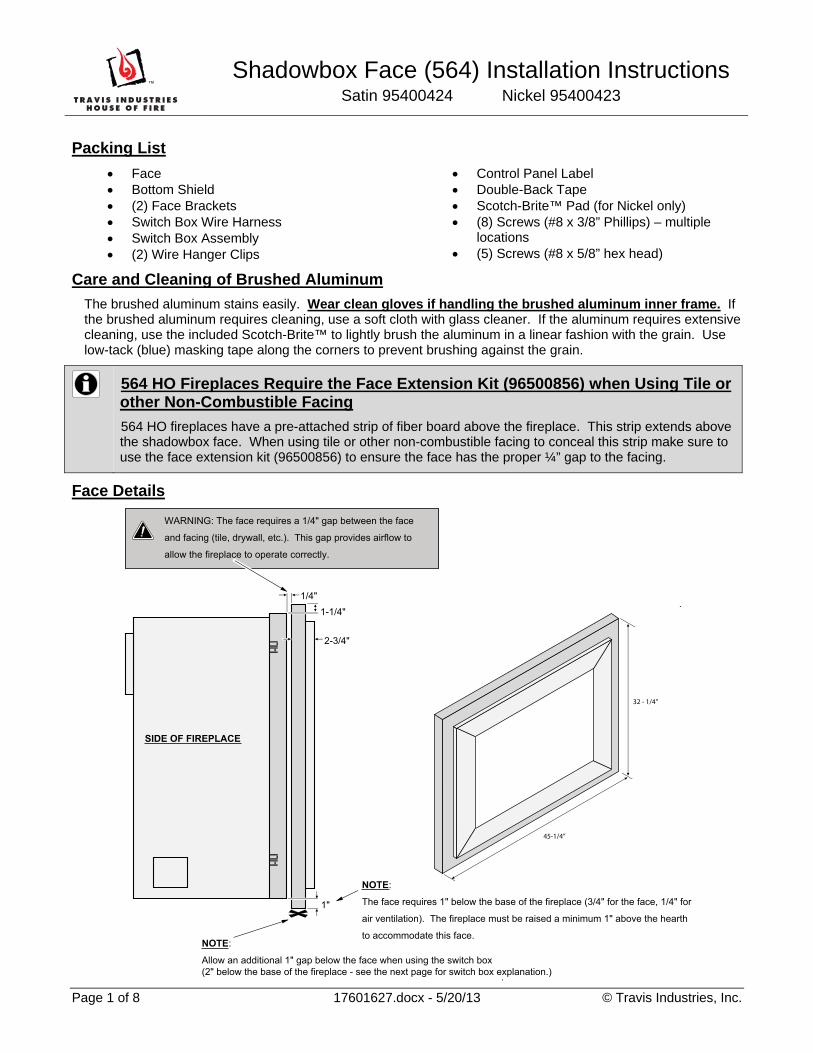
Face Details
SIDE OF FIREPLACE
1"
NOTE:
Allow an additional 1" gap below the face when using the switch box (2" below the base of the fireplace - see the next page for switch box explanation.)
.
WARNING: The face requires a 1/4" gap between the face
and facing (tile, drywall, etc.). This gap provides airflow to
allow the fireplace to operate correctly.
1/4"1-1/4"
2-3/4"
NOTE:
The face requires 1" below the base of the fireplace (3/4" for the face, 1/4" for
air ventilation). The fireplace must be raised a minimum 1" above the hearth
to accommodate this face.
.
32 - 1/4”
45-1/4”

Shadowbox Face (564) Installation Instructions Satin 95400424 Nickel 95400423
Page 2 of 8 17601627.docx - 11/1/12 © Travis Industries, Inc.
Switch Box Installation
This face does not have a door to allow access to the controls. The installer must install one of two options:
a) For a 564 HO GSR2 the switchbox is not necessary. For the other 564 units, if you install a GreenSmart™ #1 or #2 (GSR or GSR2) then the switchbox is not required either. NOTE: You may wish to install the switchbox with the GreenSmart™ #1 remote to allow the accent light rheostat to be placed in an accessible location under the face. This allows the homeowner to adjust accent light brightness without removing the face.
b) Install the switchbox included with this face. The switch box positions the controls in an accessible location under the face.
To install the switch box, follow the instructions below.
1 Disconnect power to the fireplace (use circuit breaker if necessary). Remove the concealment cover from the fireplace (it lifts up and off the mounting brackets – see owner’s manual). Remove the four screws securing the control panel to allow access to the wiring. Carefully press on the back side of the on/off switch to disconnect it from the control panel (you may wish to disconnect the small plate on the control panel for better access). Disconnect the on/off switch wires (see Figure 1).
Figure 1
2 Pull the knob off the accent light rheostat. Unscrew the rheostat nut to remove the rheostat from the control panel. Disconnect the two wires leading to this rheostat (see Figure 2).
Figure 2

Shadowbox Face (564) Installation Instructions Satin 95400424 Nickel 95400423
Page 3 of 8 17601627.docx - 11/1/12 © Travis Industries, Inc.
3 If using an optional blower, remove the blower rheostat (see step 2 above for rheostat removal). NOTE: The blower rheostat and accent light rheostat use different connectors. Label the rheostats, if necessary, to ensure correct orientation.
4 Connect the wires labeled ON/OFF on the Switch Box wiring harness to the on/off wires on the fireplace (see Figure 3). NOTE: The wire harness has unique ends. Make sure to use the correct end.
Figure 3
5 Connect the wires labeled LIGHT CONTROL on the Switch Box wiring harness to the accent light wires on the fireplace (see Figure 4). If using an optional blower, connect the wires labeled FAN CONTROL on the Switch Box wiring harness to the blower wires on the fireplace.
Figure 4
Shadowbox Face (564) Installation Instructions Satin 95400424 Nickel 95400423
Page 4 of 8 17601627.docx - 11/1/12 © Travis Industries, Inc.
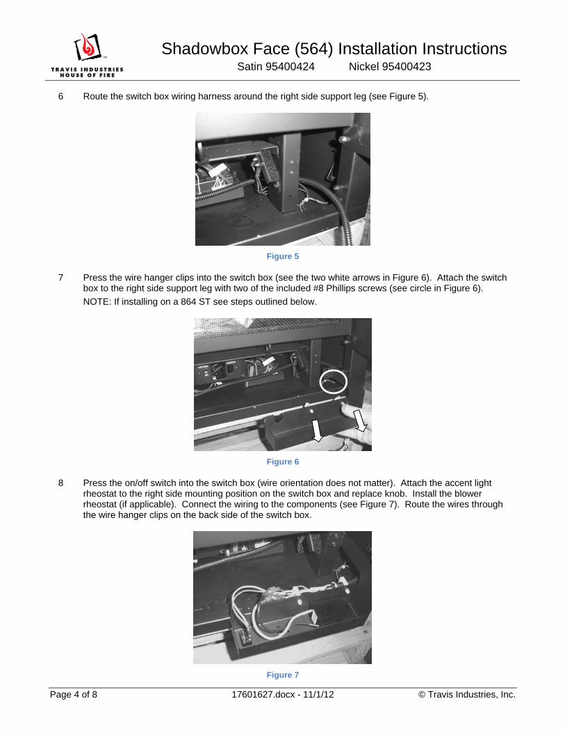
6 Route the switch box wiring harness around the right side support leg (see Figure 5).
Figure 5
7 Press the wire hanger clips into the switch box (see the two white arrows in Figure 6). Attach the switch box to the right side support leg with two of the included #8 Phillips screws (see circle in Figure 6).
NOTE: If installing on a 864 ST see steps outlined below.
Figure 6
8 Press the on/off switch into the switch box (wire orientation does not matter). Attach the accent light rheostat to the right side mounting position on the switch box and replace knob. Install the blower rheostat (if applicable). Connect the wiring to the components (see Figure 7). Route the wires through the wire hanger clips on the back side of the switch box.
Figure 7
Shadowbox Face (564) Installation Instructions Satin 95400424 Nickel 95400423
Page 5 of 8 17601627.docx - 11/1/12 © Travis Industries, Inc.
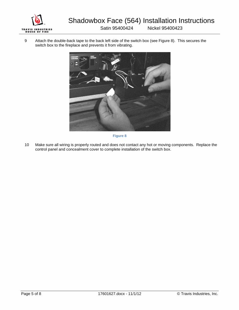
9 Attach the double-back tape to the back left side of the switch box (see Figure 8). This secures the switch box to the fireplace and prevents it from vibrating.
Figure 8
10 Make sure all wiring is properly routed and does not contact any hot or moving components. Replace the control panel and concealment cover to complete installation of the switch box.

Shadowbox Face (564) Installation Instructions Satin 95400424 Nickel 95400423
Page 6 of 8 17601627.docx - 11/1/12 © Travis Industries, Inc.
Face Installation
1 Remove the glass frame (see owner’s manual for details). Remove the two mounting bracket nuts and bushings (see “a” in Figure 9). Use the included #8 Phillips screws to attach the face brackets (see “b” in Figure 9 – make sure to use the correct offset hole for the facing being used). Replace the nuts removed earlier (without bushings) to further secure the brackets.
Figure 9
WARNING: The face requires a ¼” gap between the face and facing (tile, drywall, etc.). This gap provides airflow to allow the fireplace to operate correctly.
2 The bottom shield must be mounted to the face prior to installation. Pre-thread the five holes in the aluminum extrusion on the back side of the face (use one or more of the #8 x 5/8” Hex Head Screws - see Figure 10). Attach the bottom shield to the face using these screws (see Figure 11).
Special Instructions for Brushed Aluminum
Make sure to handle the brushed aluminum with gloves to prevent staining.
Figure 10
Figure 11
a
b
Pre-Threading Holes
Bottom Shield
#8 x 5/8” Hex Head Screws

Shadowbox Face (564) Installation Instructions Satin 95400424 Nickel 95400423
Page 7 of 8 17601627.docx - 11/1/12 © Travis Industries, Inc.
3 Replace the glass frame. With the face centered on the fireplace, lift the face up and hang it on the upper hooks on the face mounting brackets (see Figure 12).
Operation Note for Units Without GreenSmart Remote
The face conceals the flame height adjustment knob on units not using the GreenSmart remote. Make sure to adjust the flame height to high before installing the face (or to other desirable setting).
4 With the face centered, lift up on it slightly while pushing the bottom inward (see Figure 13). The face should engage the lower hooks and slide down, securely in place.
Special Instructions for Brushed Aluminum
Make sure to handle the brushed aluminum with gloves to prevent staining.
Figure 12
Figure 13
Shadowbox Face (564) Installation Instructions Satin 95400424 Nickel 95400423
Page 8 of 8 17601627.docx - 11/1/12 © Travis Industries, Inc.
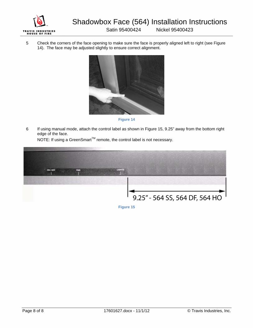
5 Check the corners of the face opening to make sure the face is properly aligned left to right (see Figure 14). The face may be adjusted slightly to ensure correct alignment.
Figure 14
6 If using manual mode, attach the control label as shown in Figure 15, 9.25” away from the bottom right edge of the face.
NOTE: If using a GreenSmartTM remote, the control label is not necessary.
Figure 15
9.25” - 564 SS, 564 DF, 564 HO