click boards meet Arduino - Mikroelektronika · Page 4 Flip&Click PIC32MZ is a two-sided...
15
click boards ™ meet Arduino
Transcript of click boards meet Arduino - Mikroelektronika · Page 4 Flip&Click PIC32MZ is a two-sided...
click boards™ meet Arduino

I want to express my thanks to you for being interested in our products and for
having confidence in MikroElektronika.
The primary aim of our company is to design and produce high quality electronic
products and to constantly improve the performance thereof in order to better
suit your needs.
To our valued customers
Nebojsa Matic
General Manager

Page 3
Table of Contents
Introduction to Flip&Click 4
1. What’s on board? 5
2. Programming Flip&Click 6
Using Flip&Click with Arduino IDE
Using Flip&Click with mikroC, mikroBasic
and mikroPascal
4. Red side 9
5. USB ports 10
6. White side 11
7. click boards™ 12
8. Schematic 13

Page 4
Flip&Click PIC32MZ is a two-sided development board with a split personality. It can be
used whit chipKIT core (Arduino-style development environment), but it can also be used
with mikroC, mikroBasic and mikroPascal.
With more than 300 bite-sized click boards™ to pick from (and more coming out every
week), anything goes. All sorts of sensors, transceivers, encoders, displays, connection
ports are at your disposal. Separate communication lines allow for thousands of click board
combinations, with no need for unsightly stacking or wire jumping. Flip&Click PIC32MZ is a
perfect sidekick for your adventures in Maker land.
A maker’s sidekick
Page 5
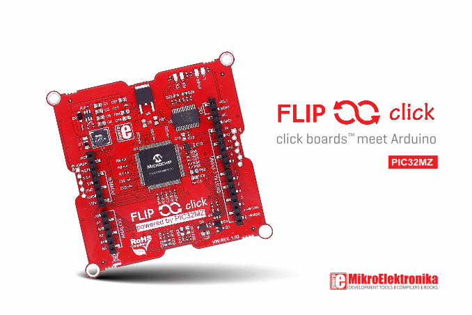
1. What’s on board?
System specification
1 mikroBUS™ socket (one of 4)
2 Reset button
3 LED (one of 4)
1 USB/UART port
2 host/device USB port
3 Signal LEDs
4 PIC32MZ2048EFH100 MCU
5 Arduino pinout
6 24 MHz Crystal oscilator
7 PICkit 3 connector
8 mikroProg connector
power supply
via USB cable
(5V DC)
board dimensions
73 x 73 mm
(2.87 x 2.87 inch)
weight
30 g (0.066 lbs)
mikroBUS™
4 sockets
1
34
6
55
5
5
2
1 32
78
Page 6
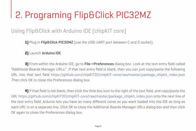
Using Flip&Click with Arduino IDE (chipKIT core)
1) Plug in Flip&Click PIC32MZ (use the USB-UART port between C and D socket).
2) Launch Arduino IDE
3) From within the Arduino IDE, go to File->Preferences dialog box. Look at the text entry field called “Additional Boards Manager URLs:” .If that text entry field is blank, then you can just copy/paste the following URL into that text field https://github.com/chipKIT32/chipKIT-core/raw/master/package_chipkit_index.json .Then click OK to close the Preferences dialog box.
4) If that field is not blank, then click the little box icon to the right of the text field, and copy/paste the URL https://github.com/chipKIT32/chipKIT-core/raw/master/package_chipkit_index.json onto the next line of the text entry field. Arduino lets you have as many different cores as you want loaded into the IDE as long as each URL is on a separate line. Click OK to close the Additional Boards Manager URLs dialog box and then click OK again to close the Preferences dialog box.
2. Programing Flip&Click PIC32MZ

Page 7
5) Now select the Tools->Board->Board Manager menu from the Arduino IDE, and it will open up the Boards Manager window. From there, scroll down until you see the chipKIT board. Click once on any of the text in the chipKIT section, and you will see a button appear that says “Install”. It will take some time to download all of the chipKIT components and install them, but when it’s done, you can click the Close button to close the Board Manager window.
6) Now choose a Mikroelektronika Flip N Click MZ board from the Tools -> Board menu and program your Flip&Click board!
7) Start writing Arduino sketches.
Page 8
We made several examples to show off the potentials of Flip & click and click board™ combinations. All the code is available on MikroElektronika’s GitHub channel. Keep visiting the link, as more code will be added in the future:www.github.com/mikroe/Flip_n_Click_Examples
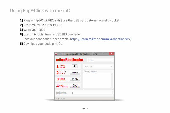
Using Flip&Click with mikroC 1) Plug in Flip&Click PIC32MZ (use the USB port between A and B socket). 2) Start mikroC PRO for PIC32 3) Write your code 4) Start mikroElektronika USB HID bootlader (see our bootloader Learn article: https://learn.mikroe.com/mikrobootloader/) 5) Download your code on MCU.

Page 9
DIGITAL (~PWM)
PINSPOWER PINS
ANALOG PINS
4. Red side
On the red side, Flip&Click PIC32MZ features a standard Arduino pinout, which makes it compatible with a range of Arduino shields. All the pins operate on 3.3V logic, just like with Arduino Due.
The four LEDs are the same as on Arduino Due. From left to right: indicating power supply (PWR), signaling programming is in progress (TX, RX), and one connected to MCU pin 43 (L).
Arduino pinout
Page 10
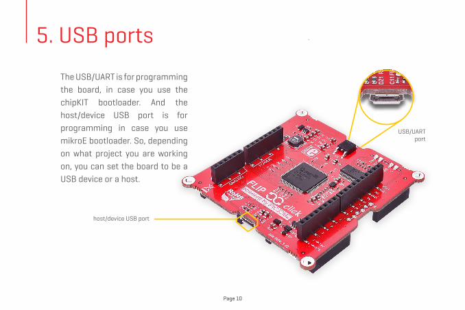
host/device USB port
The USB/UART is for programming the board, in case you use the chipKIT bootloader. And the host/device USB port is for programming in case you use mikroE bootloader. So, depending on what project you are working on, you can set the board to be a USB device or a host.
USB/UART port
5. USB ports

Page 11
6. White side
On the white side, Flip&Click PIC32MZ has four mikroBUSTM sockets along with four LEDs and a reset button. The silkscreen markings clearly denote which microcontroller pins are used on each socket. The pinout provides both 3.3V and 5V power supplies.
Page 12
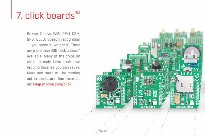
7. click boards™
click boards™
Buzzer, Relays, WiFi, RFid, GSM, GPS, OLED, Speech recognition — you name it, we got it! There are more than 300 click boards™ available. Many of the chips on clicks already have their own Arduino libraries you can reuse. More and more will be coming out in the future. See them all, on: shop.mikroe.com/click
Page 13
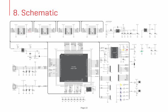
8. Schematic
12345ID
D+D-
VBUS
GND
CN1
USB MICRO
FB3
C1110nF
DZ1 DZ2
USBD_NUSBD_P
C1210µF
R1410k
SW 6
VIN 5
EN 4FB3 GND2 BOOST1U4
LM2734YMKC210µF
R110k
VIN
C310µF
D2PMGER3010ER
C1
10nF
L1
3.3µH
C410µF
VCC-5V
R310k
D1
CD1206-S01575R252.3k
VCC-5V
ANRSTCSSCKMISOMOSI3.3VGND
PWMINTRXTX
SCLSDA
5VGND
VCC-3.3V VCC-5V
A
ANRSTCSSCKMISOMOSI3.3VGND
PWMINTRXTX
SCLSDA
5VGND
VCC-3.3V VCC-5V
B
ANRSTCSSCKMISOMOSI3.3VGND
PWMINTRXTX
SCLSDA
5VGND
VCC-3.3V VCC-5V
D
ANRSTCSSCKMISOMOSI3.3VGND
PWMINTRXTX
SCLSDA
5VGND
VCC-3.3V VCC-5V
C
VO 3
GND2
VIN 1
U3
LD29080DT33R
C510µF
VCC-5V
FB1
C610µF
VCC-3.3V
VCC-3.3V VCC-3.3V
VDDANA
VDDANAVCC-3.3V
FB2
C810µF
C90.1µF
C230.1µF
C240.1µF
C250.1µF
C260.1µF
C270.1µF
C280.1µF
C290.1µF
VCC-3.3VVCC-3.3VVCC-3.3VVCC-3.3VVCC-3.3VVCC-3.3VVCC-3.3V
USBD_NUSBD_P
C220.1µF
VCC-3.3V
VBUSUART1_RX
UART1_TX
UART2_TXUART2_RX
UAR
T3_T
XU
ART3
_RX
UAR
T4_T
X
UART4_RX
UAR
T5_T
XU
ART5
_RX
SPI1
_SCK
SPI1
_SS0
SPI1
_MIS
OSP
I1_M
OSI
SPI2_SCKSP
I2_S
S0SPI2_MISO
SPI2_MOSI
SPI3
_SCK
SPI3
_SS
SPI3
_MIS
OSP
I3_M
OSI
I2C1_SCLI2C1_SDA
I2C5_SCLI2C5_SDA
I2C2_SCLI2C2_SDA
OC4OC3
OC6
OC8
AN1AN2AN3AN4
AN5
AN6AN7
AN8AN9
AN10
INT0
INT1
INT2
INT3
INT4
FM1 FM2 FM3 FM4
123456789
1011121314 15
16171819202122232425262728
TXDDTR#RTS#VCCIORXDRI#GNDNCDSR#DCD#CTS#CBUS4CBUS2CBUS3
CBUS0CBUS1
OSCOOSCITESTAGND
NC
GND
GND
VCCRESET#
3V3OUTUSBDMUSBDP
FT232RL
U2
FT232RLC130.1µF
VCC-3.3V VCC-3.3V
C140.1µF
C150.1µF
VCC-3.3VVCC-3.3V
VCC-3.3V
USB_TX
USB_RX
R42.2k
R52.2k
VCC-3.3V VCC-3.3V
UART5_TX
UART5_RX
U2_USBD_NU2_USBD_P
FT232_RST
R64.7k
R1110k
FT232_RST
12345ID
D+D-
VBUS
GND
CN2
USB MICRO
FB4
C1710nF
VCC-5V
DZ3 DZ4
U2_USBD_NU2_USBD_P
U2_VCC-USB
U2_VCC-USB
12345678
J3
HF 1x8
12345678
J2
HF 1x8
12345678910
J1
F1X10
123456
J4
HF 1x6
RST
VIN
VCC-3.3VVCC-5V
RST
I2C5_SCLI2C5_SDA
LD3
R10470
VCC-3.3V
C1010µF
C1810µF
R16 27
R17 27
R27 27
R33
27
R34
27
R35
27
R9
27R
827
R7
27
RESET
RST
R1510k
VCC-3.3V
PGC
PGD
C7 0.1µFRST
T2
T1
UART3_TXUART3_RX
UART4_TXUART4_RX UART1_RX
UART1_TX UART2_TXUART2_RX
I2C1_SCLI2C1_SDA
I2C2_SCLI2C2_SDA
I2C1_SCLI2C1_SDA
I2C2_SCLI2C2_SDA
INT1 INT2INT3INT4
SPI1_SCKSPI1_MISOSPI1_MOSI
SPI1_SCKSPI1_MISOSPI1_MOSI
SPI2_SCKSPI2_MISOSPI2_MOSI
SPI2_SCKSPI2_MISOSPI2_MOSI
AN1AN2AN3AN4AN5AN6
SPI3_SCKSPI3_MISOSPI3_MOSI
UART5_TXUART5_RX
AN7 AN8AN9AN10
R18 1k
OC4 OC3OC7OC6
OC1
OC5OC8
OC2OC9
OC2OC9
INT0
RST1 RST2RST3RST4
RST1
RST2
RST3
RST4
SPI2_SS0 SPI1_SS0SPI2_SS1 SPI1_SS1
SPI2_SS1
SPI1
_SS1
SPI3_SS
R30
10kR3110k
VCC-3.3V
R37
10kR3910k
VCC-3.3V
BTN1
BTN2
BTN2BTN1
GPIO1
GPIO2
GPIO1
GPIO2
R12 27
R13 27
R19 27
R20 27
LED
ALE
DB
LED
C
LED
D
LEDA
LEDB
LEDC
LEDD
R29
1k
R32
1k
R36
1k
R38
1k
LEDA
LEDB
LEDC
LEDD
L
R28
1kSPI3_SCK
VCC-3.3V
RST
PGDPGC
OC1
OC5
STANDBY1
GND2 OUT 3
VCC 4Y1
24MHz
C190.1µF
VCC-3.3V
456
123
J5
ICSP
30292827 3433
58575655545352
463635 42 43 44 4537 50
9
48 49
1112
32
72
69686766656463
43
78 77
2423
181716151413
5678
10
7980
12
22212019
62616059
38 39 40 41 47
71
31
51
70
26
25
76
757473
100pin LQFP
81828384858687888990919293949596979899100
RB13
RB12
RE7RC1RC2RC3
RD10RD9
RA15
RF3
RB15
RB14
VUSB3V3VSS
D-D+
VSS
VDD
RE0
RA7
RA6
VDD
RG0
RG1
RE6RE5
RE2
RG13
RG12
RG14 RE1
VSS
RG8
RB2RB3RB4RB5RE9RE8
RD0RD11
VBUS
RF5
VDD
RG7RG6
RA1
RE3
RE4
RG15RA5
RB0RB1
RC12
/OSC
1RC
15/O
SC2
RA14
RA3
RD14
RD15
RF2
RF13
VDD
RF8
RA4
RF1
RA0RG9MCLR
VSS
RF12
RA2
RF4VSS
RC4
VDDVSS
RC13
RD3
RD1
RC14VDDVSS
RD2
RD12
RD13
RD4
AVSS
AVD
D
RB9
RB8
RB10
RB11
RB7
RA9
RB6
RA10
RD5
VDD
VSS
RF0
PIC32MZ
U1
PIC32MZ2048EFH100-I/PF
1
2
3
OUT
GND
IN5
4OCEN
U5
TPS2041B
VCC-5V
USB_VBUS
USB_PSW#
R44
10k
VBUS
D3
R4010k
USB_ID
C2110µF
VCC-5V
USB_VBUSR47 1k
VCC-5V
C2010µF
USB
_PSW
#U
SB_I
D
R4110k
VCC-3.3V
USB_OC1
USB
_OC1
32
1
Q1DMP2160UW-7
D4
45
123
J6
M1X5
RSTPGDPGC
VCC-3.3V
OC7

Page 14
DISCLAIMERAll the products owned by MikroElektronika are protected by copyright law and international copyright treaty. Therefore, this manual is to be treated as any other copyright material. No part of this manual, including product and software described herein, may be reproduced, stored in a retrieval system, translated or transmitted in any form or by any means, without the prior written permission of MikroElektronika. The manual PDF edition can be printed for private or local use, but not for distribution. Any modification of this manual is prohibited. MikroElektronika provides this manual ‘as is’ without warranty of any kind, either expressed or implied, including, but not limited to, the implied warranties or conditions of merchantability or fitness for a particular purpose. MikroElektronika shall assume no responsibility or liability for any errors, omissions and inaccuracies that may appear in this manual. In no event shall MikroElektronika, its directors, officers, employees or distributors be liable for any indirect, specific, incidental or consequential damages (including damages for loss of business profits and business information, business interruption or any other pecuniary loss) arising out of the use of this manual or product, even if MikroElektronika has been advised of the possibility of such damages. MikroElektronika reserves the right to change information contained in this manual at any time without prior notice, if necessary.
HIGH RISK ACTIVITIES
The products of MikroElektronika are not fault – tolerant nor designed, manufactured or intended for use or resale as on – line control equipment in hazardous environments requiring fail – safe performance, such as in the operation of nuclear facilities, aircraft navigation or communication systems, air traffic control, direct life support machines or weapons systems in which the failure of Software could lead directly to death, personal injury or severe physical or environmental damage (‘High Risk Activities’). MikroElektronika and its suppliers specifically disclaim any expressed or implied warranty of fitness for High Risk Activities.
TRADEMARKS
The MikroElektronika name and logo, mikroC™, mikroBasic™, mikroPascal™, Visual TFT™, Visual GLCD™, mikroProg™, Ready™, MINI™, mikroBUS™, EasyPIC™, EasyAVR™, Easy8051™, click™ boards and mikromedia™ are trademarks of MikroElektronika. All other trademarks mentioned herein are property of their respective companies.All other product and corporate names appearing in this manual may or may not be registered trademarks or copyrights of their respective companies, and are only used for identification or explanation and to the owners’ benefit, with no intent to infringe.
Copyright © 2017 MikroElektronika. All Rights Reserved.

If you want to learn more about our products, please visit our web site at www.mikroe.com. If you are experiencing some problems with any of our products or just need additional information, please place your ticket at helpdesk.mikroe.com. If you have any questions, comments or business proposals, do not hesitate to contact us at [email protected]