Classical Mechanics
364
Classical Mechanics: a Critical Introduction Michael Cohen, Professor Emeritus Department of Physics and Astronomy University of Pennsylvania Philadelphia, PA 19104-6396 Copyright 2011, 2012 with Solutions Manual by Larry Gladney, Ph.D. Edmund J. and Louise W. Kahn Professor for Faculty Excellence Department of Physics and Astronomy University of Pennsylvania ”Why, a four-year-old child could understand this... Run out and find me a four-year-old child.” - GROUCHO i
description
Classicla mechanics lecture notes
Transcript of Classical Mechanics
Classical Mechanics: a Critical Introduction
Michael Cohen, Professor EmeritusDepartment of Physics and Astronomy
University of PennsylvaniaPhiladelphia, PA 19104-6396
Copyright 2011, 2012
with Solutions Manual byLarry Gladney, Ph.D.
Edmund J. and Louise W. Kahn Professor for Faculty ExcellenceDepartment of Physics and Astronomy
University of Pennsylvania
”Why, a four-year-old child could understand this...Run out and find me a four-year-old child.”
- GROUCHO
i
REVISED PREFACE (Jan. 2013)
Anyone who has taught the “standard” Introductory Mechanics coursemore than a few times has most likely formed some fairly definite ideas re-garding how the basic concepts should be presented, and will have identified(rightly or wrongly) the most common sources of difficulty for the student.An increasing number of people who think seriously about physics peda-gogy have questioned the effectiveness of the traditional classroom with theProfessor lecturing and the students listening (perhaps). I take no positionregarding this question, but assume that a book can still have educationalvalue.
The first draft of this book was composed many years ago and wasintended to serve either as a stand-alone text or as a supplementary “tutor”for the student. My motivation was the belief that most courses hurrythrough the basic concepts too quickly, and that a more leisurely discussionwould be helpful to many students. I let the project lapse when I found thatpublishers appeared to be interested mainly in massive textbooks coveringall of first-year physics.
Now that it is possible to make this material available on the Internetto students at the University of Pennsylvania and elsewhere, I have revivedand reworked the project and hope the resulting document may be usefulto some readers. I owe special thanks to Professor Larry Gladney, whohas translated the text from its antiquated format into modern digital formand is also preparing a manual of solutions to the end-of-chapter problems.Professor Gladney is the author of many of these problems. The manualwill be on the Internet, but the serious student should construct his/her ownsolutions before reading Professor Gladney’s discussion. Conversations withmy colleague David Balamuth have been helpful, but I cannot find anyoneexcept myself to blame for errors or defects. An enlightening discussion withProfessor Paul Soven disabused me of the misconception that Newton’s FirstLaw is just a special case of the Second Law.
The Creative Commons copyright permits anyone to download and re-produce all or part of this text, with clear acknowledgment of the source.Neither the text, nor any part of it, may be sold. If you distribute all orpart of this text together with additional material from other sources, pleaseidentify the sources of all materials. Corrections, comments, criticisms, ad-ditional problems will be most welcome. Thanks.
Michael Cohen, Dept. of Physics and Astronomy, Univ. of Pa.,Phila, PA 19104-6396email: [email protected]
ii
0.1. INTRODUCTION
0.1 Introduction
Classical mechanics deals with the question of how an object moves when itis subjected to various forces, and also with the question of what forces acton an object which is not moving.
The word “classical” indicates that we are not discussing phenomena onthe atomic scale and we are not discussing situations in which an objectmoves with a velocity which is an appreciable fraction of the velocity oflight. The description of atomic phenomena requires quantum mechanics,and the description of phenomena at very high velocities requires Einstein’sTheory of Relativity. Both quantum mechanics and relativity were inventedin the twentieth century; the laws of classical mechanics were stated by SirIsaac Newton in 1687[New02].
The laws of classical mechanics enable us to calculate the trajectoriesof baseballs and bullets, space vehicles (during the time when the rocketengines are burning, and subsequently), and planets as they move aroundthe sun. Using these laws we can predict the position-versus-time relationfor a cylinder rolling down an inclined plane or for an oscillating pendulum,and can calculate the tension in the wire when a picture is hanging on awall.
The practical importance of the subject hardly requires demonstrationin a world which contains automobiles, buildings, airplanes, bridges, andballistic missiles. Even for the person who does not have any professionalreason to be interested in any of these mundane things, there is a compellingintellectual reason to study classical mechanics: this is the example parexcellence of a theory which explains an incredible multitude of phenomenaon the basis of a minimal number of simple principles. Anyone who seriouslystudies mechanics, even at an elementary level, will find the experience atrue intellectual adventure and will acquire a permanent respect for thesubtleties involved in applying “simple” concepts to the analysis of “simple”systems.
I wish to distinguish very clearly between “subtlety” and “trickery”.There is no trickery in this subject. The subtlety consists in the necessity ofusing concepts and terminology quite precisely. Vagueness in one’s think-ing and slight conceptual imprecisions which would be acceptable in every-day discourse will lead almost invariably to incorrect solutions in mechanicsproblems.
In most introductory physics courses approximately one semester (usu-ally a bit less than one semester) is devoted to mechanics. The instructorand students usually labor under the pressure of being required to “cover” a
iii
0.1. INTRODUCTION
certain amount of material. It is difficult, or even impossible, to “cover” thestandard topics in mechanics in one semester without passing too hastilyover a number of fundamental concepts which form the basis for everythingwhich follows.
Perhaps the most common area of confusion has to do with the listing ofthe forces which act on a given object. Most people require a considerableamount of practice before they can make a correct list. One must learnto distinguish between the forces acting on a thing and the forces which itexerts on other things, and one must learn the difference between real forces(pushes and pulls caused by the action of one material object on another)and demons like “centrifugal force” (the tendency of an object moving in acircle to slip outwards) which must be expunged from the list of forces.
An impatient reader may be annoyed by amount of space devoted todiscussion of “obvious” concepts such as “force”, “tension”, and “friction”.The reader (unlike the student who is trapped in a boring lecture) is, ofcourse, free to turn to the next page. I believe, however, that life is longenough to permit careful consideration of fundamental concepts and thattime thus spent is not wasted.
With a few additions (some discussion of waves for example) this bookcan serve as a self-contained text, but I imagine that most readers woulduse it as a supplementary text or study guide in a course which uses anothertextbook. It can also serve as a text for an online course.
Each chapter includes a number of Examples, which are problems re-lating to the material in the chapter, together with solutions and relevantdiscussion. None of these Examples is a “trick” problem, but some containfeatures which will challenge at least some of the readers. I strongly recom-mend that the reader write out her/his own solution to the Example beforereading the solution in the text.
Some introductory Mechanics courses are advertised as not requiring anyknowledge of calculus, but calculus usually sneaks in even if anonymously(e.g. in the derivation of the acceleration of a particle moving in a circleor in the definition of work and the derivation of the relation between workand kinetic energy).
Since Mechanics provides good illustrations of the physical meaning ofthe “derivative” and the “integral”, we introduce and explain these mathe-matical notions in the appropriate context. At no extra charge the readerwho is not familiar with vector notation and vector algebra will find a dis-cussion of those topics in Appendix A.
iv
Contents
0.1 Introduction . . . . . . . . . . . . . . . . . . . . . . . . . . . . iii
1 KINEMATICS: THE MATHEMATICAL DESCRIPTIONOF MOTION 1
1.1 Motion in One Dimension . . . . . . . . . . . . . . . . . . . . 1
1.2 Acceleration . . . . . . . . . . . . . . . . . . . . . . . . . . . . 6
1.3 Motion With Constant Acceleration . . . . . . . . . . . . . . 7
1.4 Motion in Two and Three Dimensions . . . . . . . . . . . . . 10
1.4.1 Circular Motion: Geometrical Method . . . . . . . . . 12
1.4.2 Circular Motion: Analytic Method . . . . . . . . . . . 14
1.5 Motion Of A Freely Falling Body . . . . . . . . . . . . . . . . 15
1.6 Kinematics Problems . . . . . . . . . . . . . . . . . . . . . . . 20
1.6.1 One-Dimensional Motion . . . . . . . . . . . . . . . . 20
1.6.2 Two and Three Dimensional Motion . . . . . . . . . . 21
2 NEWTON’S FIRST AND THIRD LAWS: STATICS OFPARTICLES 25
2.1 Newton’s First Law; Forces . . . . . . . . . . . . . . . . . . . 25
2.2 Inertial Frames . . . . . . . . . . . . . . . . . . . . . . . . . . 28
2.3 Quantitative Definition of Force; Statics of Particles . . . . . 30
2.4 Examples of Static Equilibrium of Particles . . . . . . . . . . 32
2.5 Newton’s Third Law . . . . . . . . . . . . . . . . . . . . . . . 38
2.6 Ropes and Strings; the Meaning of “Tension” . . . . . . . . . 43
2.7 Friction . . . . . . . . . . . . . . . . . . . . . . . . . . . . . . 52
2.8 Kinetic Friction . . . . . . . . . . . . . . . . . . . . . . . . . . 63
2.9 Newton’s First Law of Motion Problems . . . . . . . . . . . . 67
3 NEWTON’S SECOND LAW; DYNAMICS OF PARTICLES 69
3.1 Dynamics Of Particles . . . . . . . . . . . . . . . . . . . . . . 69
3.2 Motion of Planets and Satellites; Newton’s Law of Gravitation 94
v
CONTENTS CONTENTS
3.3 Newton’s 2nd Law of Motion Problems . . . . . . . . . . . . . 101
4 CONSERVATION AND NON-CONSERVATION OF MO-MENTUM 105
4.1 PRINCIPLE OF CONSERVATION OF MOMENTUM . . . 105
4.2 Center of Mass . . . . . . . . . . . . . . . . . . . . . . . . . . 111
4.3 Time-Averaged Force . . . . . . . . . . . . . . . . . . . . . . . 115
4.4 Momentum Problems . . . . . . . . . . . . . . . . . . . . . . . 122
5 WORK AND ENERGY 125
5.1 Definition of Work . . . . . . . . . . . . . . . . . . . . . . . . 125
5.2 The Work-Energy Theorem . . . . . . . . . . . . . . . . . . . 127
5.3 Potential Energy . . . . . . . . . . . . . . . . . . . . . . . . . 136
5.4 More General Significance of Energy (Qualitative Discussion) 142
5.5 Elastic and Inelastic Collisions . . . . . . . . . . . . . . . . . 143
5.5.1 Relative Velocity in One-Dimensional Elastic Collisions 147
5.5.2 Two Dimensional Elastic Collisions . . . . . . . . . . . 147
5.6 Power and Units of Work . . . . . . . . . . . . . . . . . . . . 149
5.7 Work and Conservation of Energy Problems . . . . . . . . . . 151
6 SIMPLE HARMONIC MOTION 155
6.1 Hooke’s Law and the Differential Equation for Simple Har-monic Motion . . . . . . . . . . . . . . . . . . . . . . . . . . . 155
6.2 Solution by Calculus . . . . . . . . . . . . . . . . . . . . . . . 157
6.3 Geometrical Solution of the Differential Equation of SimpleHarmonic Motion; the Circle of Reference . . . . . . . . . . . 163
6.4 Energy Considerations in Simple Harmonic Motion . . . . . . 165
6.5 Small Oscillations of a Pendulum . . . . . . . . . . . . . . . . 166
6.6 Simple Harmonic Oscillation Problems . . . . . . . . . . . . . 172
7 Static Equilibrium of Simple Rigid Bodies 175
7.1 Definition of Torque . . . . . . . . . . . . . . . . . . . . . . . 176
7.2 Static Equilibrium of Extended Bodies . . . . . . . . . . . . . 177
7.3 Static Equilibrium Problems . . . . . . . . . . . . . . . . . . . 192
8 Rotational Motion, Angular Momentum and Dynamics ofRigid Bodies 195
8.1 Angular Momentum and Central Forces . . . . . . . . . . . . 196
8.2 Systems Of More Than One Particle . . . . . . . . . . . . . . 199
8.3 Simple Rotational Motion Examples . . . . . . . . . . . . . . 203
vi
CONTENTS CONTENTS
8.4 Rolling Motion . . . . . . . . . . . . . . . . . . . . . . . . . . 211
8.5 Work-Energy for Rigid Body Dynamics . . . . . . . . . . . . 222
8.6 Rotational Motion Problems . . . . . . . . . . . . . . . . . . . 231
9 REMARKS ON NEWTON’S LAW OF UNIVERSAL GRAV-ITATION - contributed by Larry Gladney 235
9.1 Determination of g . . . . . . . . . . . . . . . . . . . . . . . . 236
9.2 Kepler’s First Law of Planetary Motion . . . . . . . . . . . . 239
9.3 Gravitational Orbit Problems . . . . . . . . . . . . . . . . . . 246
10 APPENDICES 247
A Appendix A 249
A.1 Vectors . . . . . . . . . . . . . . . . . . . . . . . . . . . . . . 249
A.1.1 Definitions and Proofs . . . . . . . . . . . . . . . . . . 250
B Appendix B 261
B.1 Useful Theorems about Energy, Angular Momentum, & Mo-ment of Inertia . . . . . . . . . . . . . . . . . . . . . . . . . . 261
C Appendix C 265
C.1 Proof That Force Is A Vector . . . . . . . . . . . . . . . . . . 265
D Appendix D 269
D.1 Equivalence of Acceleration of Axes and a Fictional Gravita-tional Force . . . . . . . . . . . . . . . . . . . . . . . . . . . . 269
E Appendix E 271
E.1 Developing Your Problem-Solving Skills: Helpful(?) Sugges-tions . . . . . . . . . . . . . . . . . . . . . . . . . . . . . . . . 271
PREFACE TO SOLUTIONS MANUAL 273
1 KINEMATICS 275
1.1 Kinematics Problems Solutions . . . . . . . . . . . . . . . . . 275
1.1.1 One-Dimensional Motion . . . . . . . . . . . . . . . . 275
1.1.2 Two and Three Dimensional Motion . . . . . . . . . . 280
2 NEWTON’S FIRST AND THIRD LAWS 283
2.1 Newton’s First and Third Laws of Motion Solutions . . . . . 283
vii
CONTENTS CONTENTS
3 NEWTON’S SECOND LAW 2893.1 Newton’s Second Law of Motion Problem Solutions . . . . . . 289
4 MOMENTUM 3034.1 Momentum Problem Solutions . . . . . . . . . . . . . . . . . 303
5 WORK AND ENERGY 3115.1 Work and Conservation of Energy Problem Solutions . . . . . 311
6 Simple Harmonic Motion 3216.1 Simple Harmonic Motion Problem Solutions . . . . . . . . . . 321
7 Static Equilibrium of Simple Rigid Bodies 3257.1 Static Equilibrium Problem Solutions . . . . . . . . . . . . . 325
8 Rotational Motion, Angular Momentum and Dynamics ofRigid Bodies 3338.1 Rotational Motion Problem Solutions . . . . . . . . . . . . . 333
9 Remarks on Gravitation 3499.1 Remarks on Gravity Problem Solutions . . . . . . . . . . . . 349
viii
Chapter 1
KINEMATICS: THEMATHEMATICALDESCRIPTION OFMOTION
Kinematics is simply the mathematical description of motion, and makesno reference to the forces which cause the motion. Thus, kinematics is notreally part of physics but provides us with the mathematical frameworkwithin which the laws of physics can be stated in a precise way.
1.1 Motion in One Dimension
Let us think about a material object (a “particle”) which is constrained tomove along a given straight line (e.g. an automobile moving along a straighthighway). If we take some point on the line as an origin, the position of theparticle at any instant can be specified by a number x which gives thedistance from the origin to the particle. Positive values of x are assignedto points on one side of the origin, and negative values of x are assigned topoints on the other side of the origin, so that each value of x corresponds toa unique point. Which direction is taken as positive and which as negativeis purely a matter of convention. The numerical value of x clearly dependson the unit of length we are using (e.g. feet, meters, or miles). Unless theparticle is at rest, x will vary with time. The value of x at time t is denotedby x(t).
1
1.1. MOTION IN ONE DIMENSION
The average velocity of a particle during the time interval from t to t′
is defined as
vavg =x(t′)− x(t)
t′ − t(1.1)
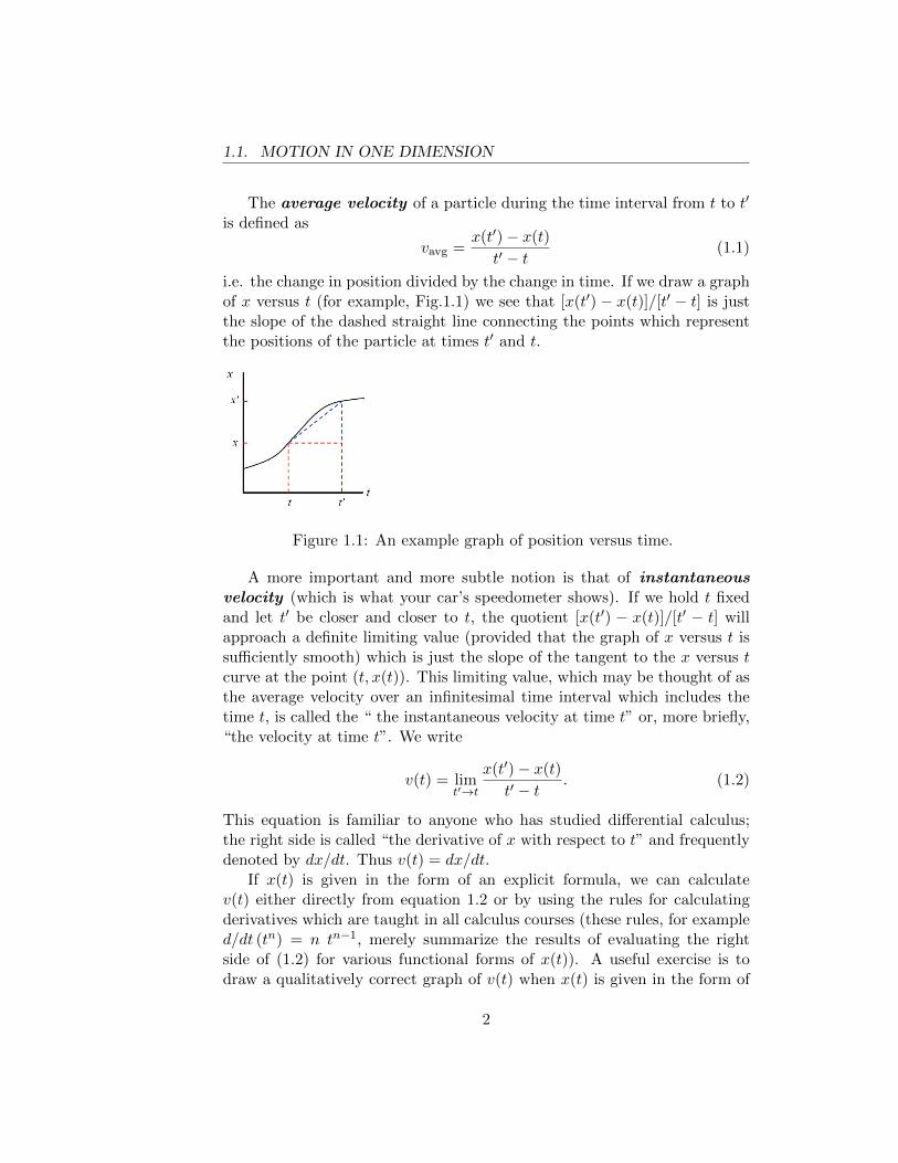
i.e. the change in position divided by the change in time. If we draw a graphof x versus t (for example, Fig.1.1) we see that [x(t′) − x(t)]/[t′ − t] is justthe slope of the dashed straight line connecting the points which representthe positions of the particle at times t′ and t.
Figure 1.1: An example graph of position versus time.
A more important and more subtle notion is that of instantaneousvelocity (which is what your car’s speedometer shows). If we hold t fixedand let t′ be closer and closer to t, the quotient [x(t′) − x(t)]/[t′ − t] willapproach a definite limiting value (provided that the graph of x versus t issufficiently smooth) which is just the slope of the tangent to the x versus tcurve at the point (t, x(t)). This limiting value, which may be thought of asthe average velocity over an infinitesimal time interval which includes thetime t, is called the “ the instantaneous velocity at time t” or, more briefly,“the velocity at time t”. We write
v(t) = limt′→t
x(t′)− x(t)
t′ − t. (1.2)
This equation is familiar to anyone who has studied differential calculus;the right side is called “the derivative of x with respect to t” and frequentlydenoted by dx/dt. Thus v(t) = dx/dt.
If x(t) is given in the form of an explicit formula, we can calculatev(t) either directly from equation 1.2 or by using the rules for calculatingderivatives which are taught in all calculus courses (these rules, for exampled/dt (tn) = n tn−1, merely summarize the results of evaluating the rightside of (1.2) for various functional forms of x(t)). A useful exercise is todraw a qualitatively correct graph of v(t) when x(t) is given in the form of
2
1.1. MOTION IN ONE DIMENSION
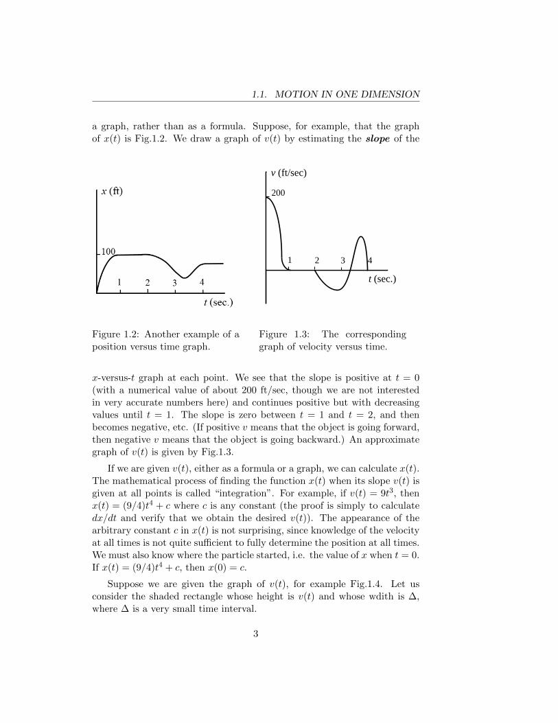
a graph, rather than as a formula. Suppose, for example, that the graphof x(t) is Fig.1.2. We draw a graph of v(t) by estimating the slope of the
Figure 1.2: Another example of aposition versus time graph.
v (ft/sec)
t (sec.)
1 2 3 4
200
Figure 1.3: The correspondinggraph of velocity versus time.
x-versus-t graph at each point. We see that the slope is positive at t = 0(with a numerical value of about 200 ft/sec, though we are not interestedin very accurate numbers here) and continues positive but with decreasingvalues until t = 1. The slope is zero between t = 1 and t = 2, and thenbecomes negative, etc. (If positive v means that the object is going forward,then negative v means that the object is going backward.) An approximategraph of v(t) is given by Fig.1.3.
If we are given v(t), either as a formula or a graph, we can calculate x(t).The mathematical process of finding the function x(t) when its slope v(t) isgiven at all points is called “integration”. For example, if v(t) = 9t3, thenx(t) = (9/4)t4 + c where c is any constant (the proof is simply to calculatedx/dt and verify that we obtain the desired v(t)). The appearance of thearbitrary constant c in x(t) is not surprising, since knowledge of the velocityat all times is not quite sufficient to fully determine the position at all times.We must also know where the particle started, i.e. the value of x when t = 0.If x(t) = (9/4)t4 + c, then x(0) = c.
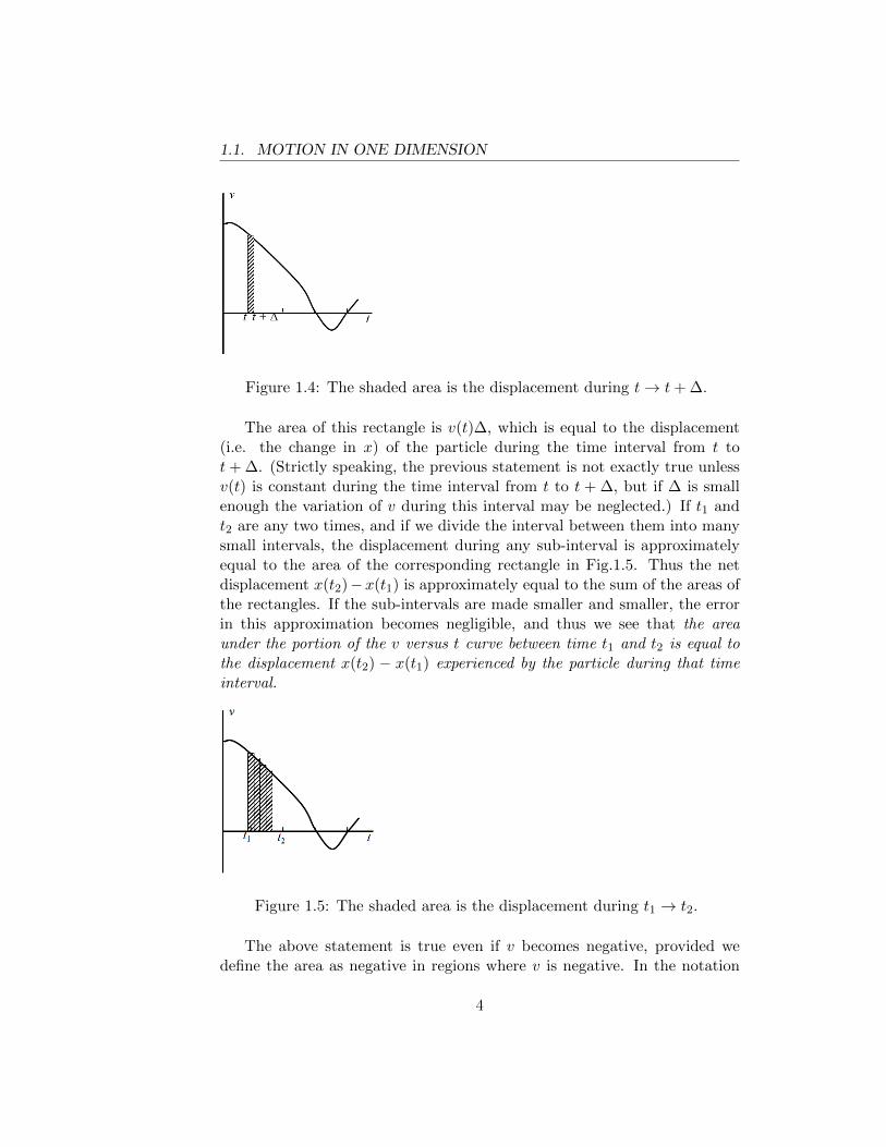
Suppose we are given the graph of v(t), for example Fig.1.4. Let usconsider the shaded rectangle whose height is v(t) and whose wdith is ∆,where ∆ is a very small time interval.
3
1.1. MOTION IN ONE DIMENSION
Figure 1.4: The shaded area is the displacement during t→ t+ ∆.
The area of this rectangle is v(t)∆, which is equal to the displacement(i.e. the change in x) of the particle during the time interval from t tot+ ∆. (Strictly speaking, the previous statement is not exactly true unlessv(t) is constant during the time interval from t to t + ∆, but if ∆ is smallenough the variation of v during this interval may be neglected.) If t1 andt2 are any two times, and if we divide the interval between them into manysmall intervals, the displacement during any sub-interval is approximatelyequal to the area of the corresponding rectangle in Fig.1.5. Thus the netdisplacement x(t2)−x(t1) is approximately equal to the sum of the areas ofthe rectangles. If the sub-intervals are made smaller and smaller, the errorin this approximation becomes negligible, and thus we see that the areaunder the portion of the v versus t curve between time t1 and t2 is equal tothe displacement x(t2) − x(t1) experienced by the particle during that timeinterval.
Figure 1.5: The shaded area is the displacement during t1 → t2.
The above statement is true even if v becomes negative, provided wedefine the area as negative in regions where v is negative. In the notation
4
1.1. MOTION IN ONE DIMENSION
of integral calculus we write
x(t2)− x(t1) =
∫ t2
t1
v(t) dt (1.3)
The right side of eqn.(1.3) is called the “integral of v(t) with respect to tfrom t1 to t2” and is defined mathematically as the limit of the sum of theareas of the rectangles in Fig.1.5 as the width of the individual rectanglestends to zero.
18
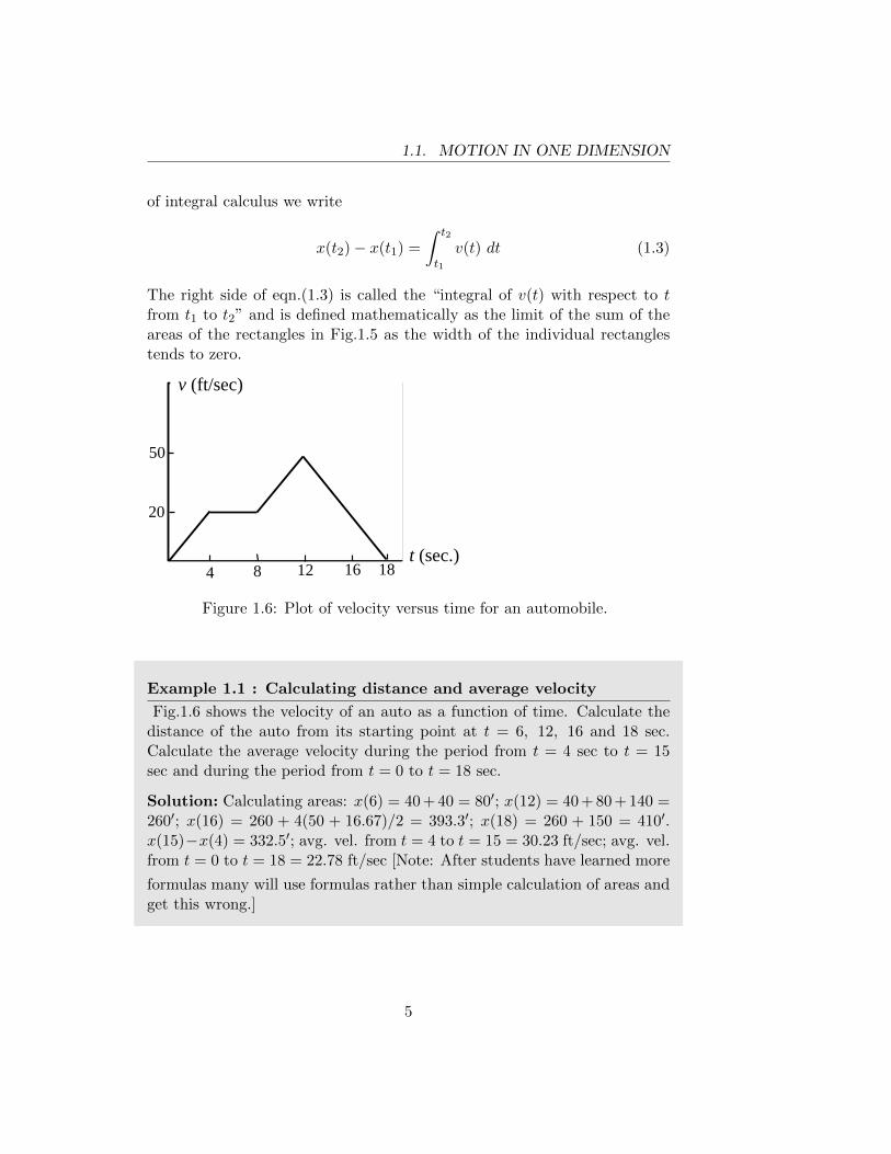
v (ft/sec)
t (sec.) 4 8 12 16
20
50
Figure 1.6: Plot of velocity versus time for an automobile.
Example 1.1 : Calculating distance and average velocity
Fig.1.6 shows the velocity of an auto as a function of time. Calculate thedistance of the auto from its starting point at t = 6, 12, 16 and 18 sec.Calculate the average velocity during the period from t = 4 sec to t = 15sec and during the period from t = 0 to t = 18 sec.
Solution: Calculating areas: x(6) = 40 + 40 = 80′; x(12) = 40 + 80 + 140 =260′; x(16) = 260 + 4(50 + 16.67)/2 = 393.3′; x(18) = 260 + 150 = 410′.x(15)−x(4) = 332.5′; avg. vel. from t = 4 to t = 15 = 30.23 ft/sec; avg. vel.from t = 0 to t = 18 = 22.78 ft/sec [Note: After students have learned more
formulas many will use formulas rather than simple calculation of areas andget this wrong.]
5
1.2. ACCELERATION
Example 1.2 :
A woman is driving between two toll booths 60 miles apart. She drives thefirst 30 miles at a speed of 40 mph. At what (constant) speed should shedrive the remaining miles so that her average speed between the toll boothswill be 50 mph?
Solution: If T is total time, 50 = 60/T , so T = 1.2 hrs. Time for first30 mi = 30/40 = 0.75 hr. Therefore, the time for the remaining 30 mi =1.2− .75 = .45 hr. The speed during the second 30 miles must be 30/.45 =66.67 mi/hr.
1.2 Acceleration
Acceleration is defined as the rate of change of velocity . The averageacceleration during the interval from t to t′ is defined as
aavg =v(t′)− v(t)
t′ − t(1.4)
where v(t′) and v(t) are the instantaneous values of the velocity at times t′
and t. The instantaneous acceleration is defined as the average accelerationover an infinitesimal time interval, i.e.
a(t) = limt′→t
v(t′)− v(t)
t′ − t(1.5)
Since v(t) = dx/dt, we can write (in the notation of calculus) a(t) = d2x/dt2.We stress that this is simply shorthand for a(t) = d/dt [dx/dt].
Comparing eqns.(1.5) and (1.2) we see that the relation between a(t)and v(t) is the same as the relation between v(t) and x(t). It follows thatif v(t) is given as a graph, the slope of the graph is a(t). If a(t) is givenas a graph then we should also expect that the area under the portion ofthe graph between time t1 and time t2 is equal to the change in velocityv(t2)− v(t1). The analogue of eqn.(1.3) is
v(t2)− v(t1) =
∫ t2
t1
a(t) dt (1.6)
6
1.3. MOTION WITH CONSTANT ACCELERATION
Example 1.3 : Instantaneous Acceleration
Draw a graph of the instantaneous acceleration a(t) if v(t) is given byFig.1.6.
1.3 Motion With Constant Acceleration
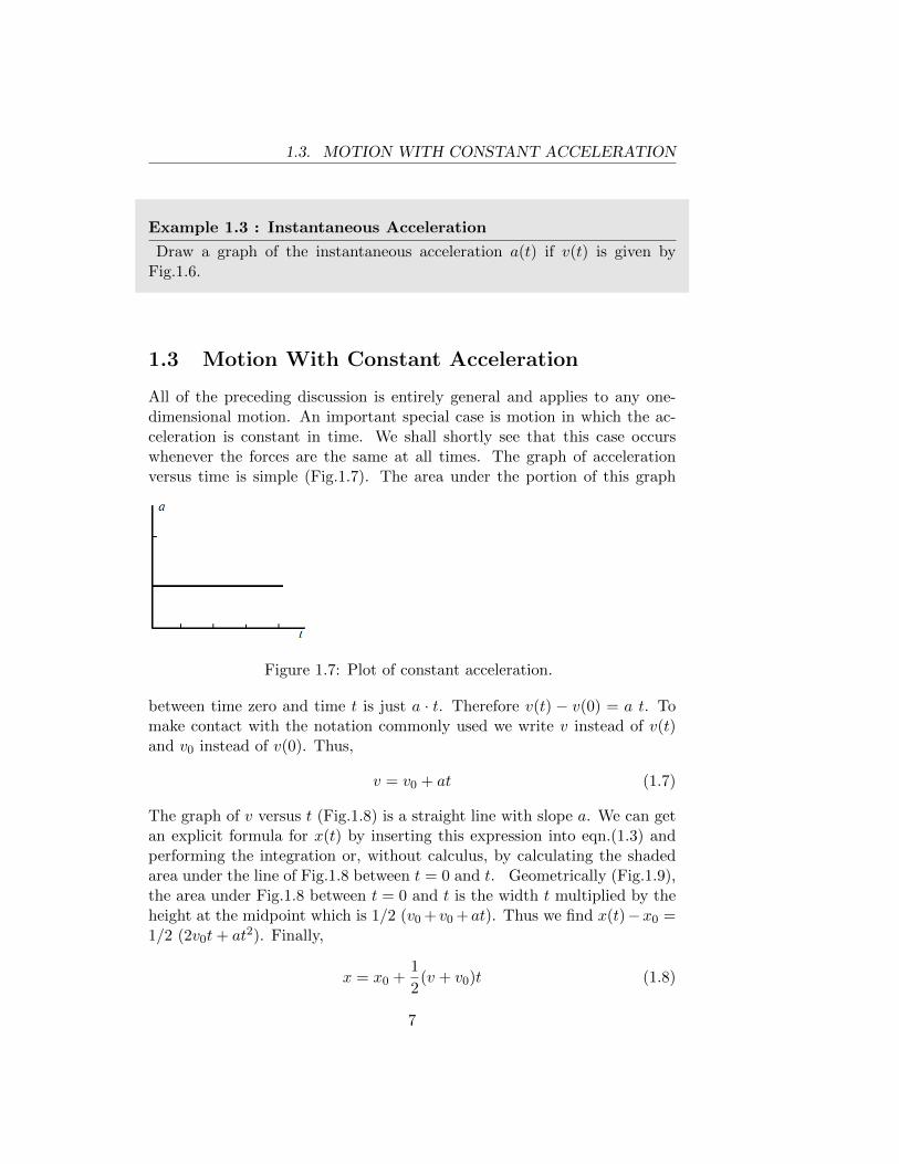
All of the preceding discussion is entirely general and applies to any one-dimensional motion. An important special case is motion in which the ac-celeration is constant in time. We shall shortly see that this case occurswhenever the forces are the same at all times. The graph of accelerationversus time is simple (Fig.1.7). The area under the portion of this graph
Figure 1.7: Plot of constant acceleration.
between time zero and time t is just a · t. Therefore v(t) − v(0) = a t. Tomake contact with the notation commonly used we write v instead of v(t)and v0 instead of v(0). Thus,
v = v0 + at (1.7)
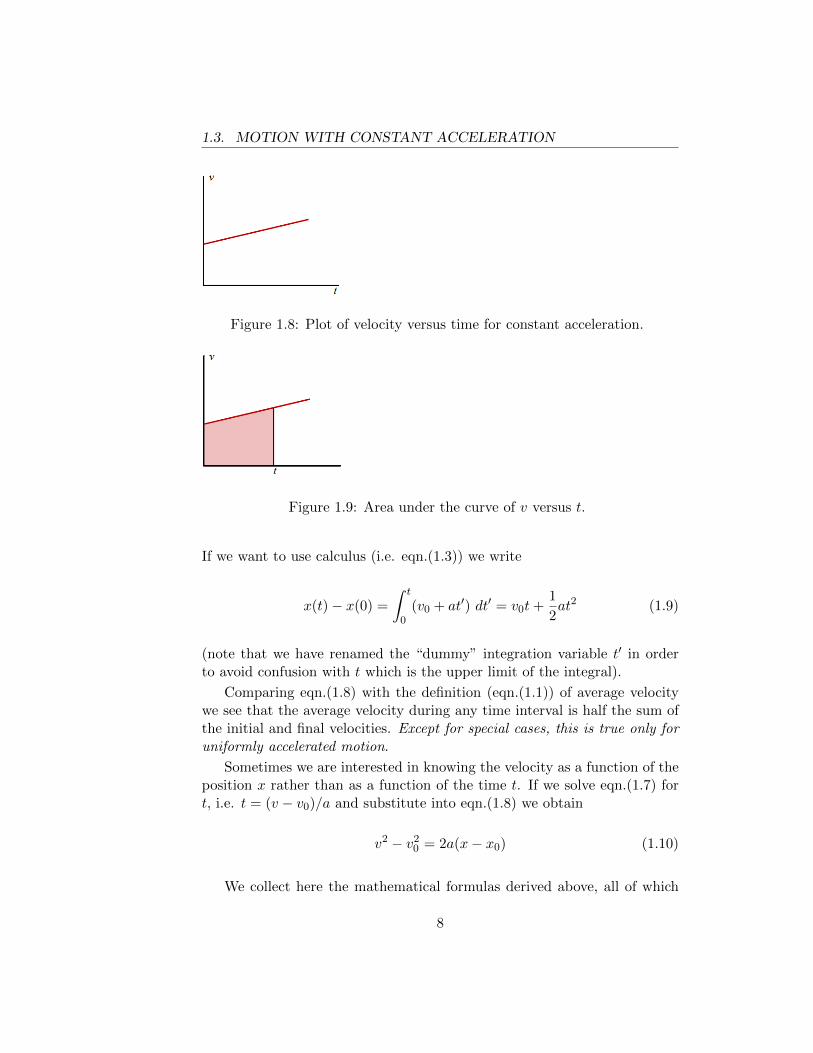
The graph of v versus t (Fig.1.8) is a straight line with slope a. We can getan explicit formula for x(t) by inserting this expression into eqn.(1.3) andperforming the integration or, without calculus, by calculating the shadedarea under the line of Fig.1.8 between t = 0 and t. Geometrically (Fig.1.9),the area under Fig.1.8 between t = 0 and t is the width t multiplied by theheight at the midpoint which is 1/2 (v0 + v0 +at). Thus we find x(t)−x0 =1/2 (2v0t+ at2). Finally,
x = x0 +1
2(v + v0)t (1.8)
7
1.3. MOTION WITH CONSTANT ACCELERATION
Figure 1.8: Plot of velocity versus time for constant acceleration.
Figure 1.9: Area under the curve of v versus t.
If we want to use calculus (i.e. eqn.(1.3)) we write
x(t)− x(0) =
∫ t
0(v0 + at′) dt′ = v0t+
1
2at2 (1.9)
(note that we have renamed the “dummy” integration variable t′ in orderto avoid confusion with t which is the upper limit of the integral).
Comparing eqn.(1.8) with the definition (eqn.(1.1)) of average velocitywe see that the average velocity during any time interval is half the sum ofthe initial and final velocities. Except for special cases, this is true only foruniformly accelerated motion.
Sometimes we are interested in knowing the velocity as a function of theposition x rather than as a function of the time t. If we solve eqn.(1.7) fort, i.e. t = (v − v0)/a and substitute into eqn.(1.8) we obtain
v2 − v20 = 2a(x− x0) (1.10)
We collect here the mathematical formulas derived above, all of which
8
1.3. MOTION WITH CONSTANT ACCELERATION
are applicable only to motion with constant acceleration .
v = v0 + at (1.11a)
x− x0 =1
2(v + v0)t (1.11b)
x = x0 + v0t+1
2at2 (1.11c)
v2 = v20 + 2a(x− x0) (1.11d)
There is often more than one way to solve a problem, but not all waysare equally efficient. Depending on what information is given and whatquestion is asked, one of the above formulas usually leads most directly tothe answer.
Example 1.4 : A constant acceleration problem
A car decelerates (with constant deceleration) from 60 mi/hr to rest in adistance of 500 ft. [Note: 60 mph = 88 ftsec]
1. Calculate the acceleration.
2. How long did it take?
3. How far did the car travel between the instant when the brake wasfirst applied and the instant when the speed was 30 mph?
4. If the car were going at 90 mph when the brakes were applied, butthe deceleration were the same as previously, how would the stoppingdistance and the stopping time change?
Solution: We will use the symbols 88 ft/s = v0, 500 ft = D.
1. 0 = v20 + 2aD ⇒ a = −7.74 ft/s2
2. T = stopping time, D = 1/2 v0T ⇒ T = 11.36 s (could also useeqn.( 1.11a))
3. D′ = answer to (3), i.e.
(1/2 v0)2 = v20 + 2aD′
(where a = − v2
0
2D
)thus
D′
D=
3
4⇒ D′ = 375 ft
9
1.4. MOTION IN TWO AND THREE DIMENSIONS
4. D′′ = answer to (4). From (d) D′′/D = (90/60)2 ⇒ D′′ = 1125 ft.From (a) the stopping time is (3/2)11.36 = 17.04 sec.
Example 1.5 : Another example of constant acceleration
A drag racer accelerates her car with constant acceleration on a straightdrag strip. She passes a radar gun (#1) which measures her instantaneousspeed at 60 ft/s and subsequently passes a second radar gun (#2) whichmeasures her instantaneous speed as 150 ft/s.
1. What is her speed at the midpoint (in time) of the interval betweenthe two measurements?
2. What is her speed when she is equidistant from the two radar guns?
3. If the distance between the two radar guns is 500 ft, how far from gun#1 is the starting point?
Solution: Symbols: v1 = 60 v2 = 150 T = time interval D = spaceinterval.
1. a = (v2 − v1)/T . At T/2 v = v1 + aT/2 = (v1 + v2)/2 = 105 ft/s.
2. v3 = speed at D/2 a = (v22 − v2
1)/2D. v23 = v2
1 + 2aD/2 = (v21 +
v22)/2 v3 = 114.24 ft/s
3. D′ = dist. from starting point to #1. v21 = 2aD′ ⇒ D′ = v2
1D/(v22 −
v21) = 95.2 ft.
1.4 Motion in Two and Three Dimensions
The motion of a particle is not necessarily confined to a straight line (con-sider, for example, a fly ball or a satellite in orbit around the earth), andin general three Cartesian coordinates, usually referred to as x(t), y(t), z(t)are required to specify the position of the particle at time t. In almost allof the situations which we shall discuss, the motion is confined to a plane;
10
1.4. MOTION IN TWO AND THREE DIMENSIONS
if we take two of our axes (e.g. the x and y axes) in the plane, then onlytwo coordinates are required to specify the position.
Extensions of the notion of velocity and acceleration to three dimen-sions is straightforward. If the coordinates of the particle at time t are(x(t), y(t), z(t)) and at t′ are (x(t′), y(t′), z(t′)), then we define the aver-age x-velocity during the time interval t → t′ by the equation vx,av =[x(t′)− x(t)]/[t′ − t]. Similar equations define vy, av and vz, av. The instan-taneous x-velocity, y-velocity, and z-velocity are defined exactly as in thecase of one-dimensional motion, i.e.
vx(t) ≡ limt′→t
x(t′)− x(t)
t− t′=dx
dt(1.12)
and so on. Similarly, we define ax,avg = [vx(t′) − vx(t)]/[t′ − t] with similardefinitions for ay, avg and az, avg. The instantaneous x-acceleration is
ax(t) ≡ limt′→t
vx(t′)− vx(t)
t′ − t=d2x
dt2(1.13)
with similar definitions of ay(t) and az(t).All of the above seems somewhat heavy-handed and it is almost obvious
that by introducing more elegant notation we could replace three equationsby a single equation. The more elegant notation, which is called vectornotation , has an even more important advantage: it enables us to state thelaws of physics in a form which is obviously independent of the orientation ofthe particular axes which we have arbitrarily chosen. The reader who is notfamiliar with vector notation and/or with the addition and subtraction ofvectors, should read the relevant part of Appendix A. The sections definingand explaining the dot product and cross product of two vectors are notrelevant at this point and may be omitted.
We introduce the symbol ~r as shorthand for the number triplet (x, y, z)formed by the three coordinates of a particle. We call ~r the position vectorof the particle and we call x, y and z the components of the positionvector with respect to the chosen set of axes. In printed text a vector isusually represented by a boldfaced letter and in handwritten or typed texta vector is usually represented by a letter with a horizontal arrow over it.1
The velocity and acceleration vectors are defined as
~v(t) = limt′→t
~r(t′)− ~r(t)t′ − t
=d~r
dt(1.14)
1Since the first version of this text was in typed format, we find it convenient to usethe arrow notation.
11
1.4. MOTION IN TWO AND THREE DIMENSIONS
and
~a(t) = limt′→t
~v(t′)− ~v(t)
t′ − t=d~v
dt=d2~r
dt2(1.15)
[Again, we stress the importance of understanding what is meant by thedifference of two vectors as explained in Appendix A.] In particular, evenif the magnitude of the velocity vector (the “speed”) remains constant, theparticle is accelerating if the direction of the velocity vector is changing.
A very important kinematical problem first solved by Newton (in theyear 1686) is to calculate the instantaneous acceleration ~a(t) of a particlemoving in a circle with constant speed. We refer to this as uniform cir-cular motion . We shall solve the problem by two methods, the first beingNewton’s.
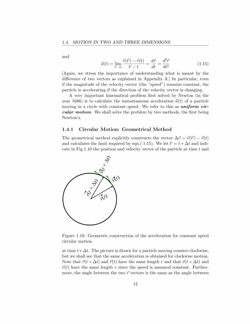
1.4.1 Circular Motion: Geometrical Method
The geometrical method explicitly constructs the vector ∆~v = ~v(t′) − ~v(t)and calculates the limit required by eqn.( 1.15). We let t′ = t+ ∆t and indi-cate in Fig.1.10 the position and velocity vector of the particle at time t and
Figure 1.10: Geometric construction of the acceleration for constant speedcircular motion.
at time t+∆t. The picture is drawn for a particle moving counter-clockwise,but we shall see that the same acceleration is obtained for clockwise motion.Note that ~r(t+ ∆t) and ~r(t) have the same length r and that ~v(t+ ∆t) and~v(t) have the same length v since the speed is assumed constant. Further-more, the angle between the two ~r vectors is the same as the angle between
12
1.4. MOTION IN TWO AND THREE DIMENSIONS
the two ~v vectors since at each instant ~v is perpendicular to ~r. During time∆t the arc-length traveled by the particle is v∆t, and the radian measure ofthe angle between ~r(t+ ∆t) and ~r(t) is (v∆t)/r.
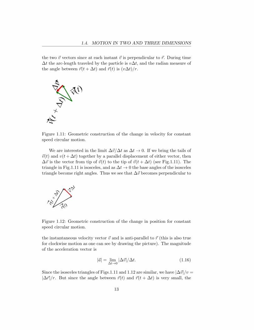
Figure 1.11: Geometric construction of the change in velocity for constantspeed circular motion.
We are interested in the limit ∆~v/∆t as ∆t→ 0. If we bring the tails of~v(t) and v(t+ ∆t) together by a parallel displacement of either vector, then∆~v is the vector from tip of ~v(t) to the tip of ~v(t+ ∆t) (see Fig.1.11). Thetriangle in Fig.1.11 is isosceles, and as ∆t→ 0 the base angles of the isoscelestriangle become right angles. Thus we see that ∆~v becomes perpendicular to
Figure 1.12: Geometric construction of the change in position for constantspeed circular motion.
the instantaneous velocity vector ~v and is anti-parallel to ~r (this is also truefor clockwise motion as one can see by drawing the picture). The magnitudeof the acceleration vector is
|~a| = lim∆t→0
|∆~v|/∆t. (1.16)
Since the isosceles triangles of Figs.1.11 and 1.12 are similar, we have |∆~v|/v =|∆~r|/r. But since the angle between ~r(t) and ~r(t + ∆t) is very small, the
13

1.4. MOTION IN TWO AND THREE DIMENSIONS
chord length |∆~r| can be replaced by the arc-length v∆t. Thus |∆~v| =v2∆t/r.
We have therefore shown that the acceleration vector has magnitudev2/r and is directed from the instantaneous position of the particle towardthe center of the circle, i.e.
~a =
(−v
2
r
)(~r
r
)= −v
2
rr (1.17)
where r is a unit vector pointing from the center of the circle toward theparticle. The acceleration which we have calculated is frequently called thecentripetal acceleration . The word “centripetal” means “directed towardthe center” and merely serves to remind us of the direction of ~a. If thespeed v is not constant, the acceleration also has a tangential component ofmagnitude dv/dt.
1.4.2 Circular Motion: Analytic Method
Figure 1.13: Geometric construction of the acceleration for constant speedcircular motion.
If we introduce unit vectors i and j (Fig.1.13) then the vector fromthe center of the circle to the instantaneous position of the particle is ~r =r[cos θ i + sin θ j] where r and θ are the usual polar coordinates. If theparticle is moving in a circle with constant speed, then dr/dt = 0 anddθ/dt = constant. So,
~v =d~r
dt= r
[− sin θ
dθ
dti+ cos θ
dθ
dtj
]. (1.18)
We have used the chain rule d/dt (cos θ) = [d/dθ (cos θ)][dθ/dt] etc. Notethat the standard differentiation formulas require that θ be expressed in
14
1.5. MOTION OF A FREELY FALLING BODY
radians. It should also be clear that ~v is tangent to the circle. Note thatv2 = (r dθ/dt)2 (sin2 θ + cos2 θ) = (r dθ/dt)2. Therefore we have
~a =d~v
dt= r
(dθ
dt
)2 [− cos θ i− sin θ j
]= −v
2
rr (1.19)
as derived above with the geometric method.
1.5 Motion Of A Freely Falling Body
It is an experimental fact that in the vicinity of a given point on the earth’ssurface, and in the absence of air resistance, all objects fall with the sameconstant acceleration. The magnitude of the acceleration is called g and isapproximately equal to 32 ft/sec2 or 9.8 meters/sec2, and the direction ofthe acceleration is down, i.e. toward the center of the earth.
The magnitude of the acceleration is inversely proportional to the squareof the distance from the center of the earth and the acceleration vector isdirected toward the center of the earth. Accordingly, the magnitude anddirection of the acceleration may be regarded as constant only within aregion whose linear dimensions are very small compared with the radius ofthe earth. This is the meaning of “in the vicinity”.
We stress that in the absence of air resistance the magnitude and di-rection of the acceleration do not depend on the velocity of the object (inparticular, if you throw a ball upward the acceleration is directed downwardwhile the ball is going up, while it is coming down, and also at the instantwhen it is at its highest point). At this stage of our discussion we cannot“derive” the fact that all objects fall with the same acceleration since wehave said nothing about forces (and about gravitational forces in particular)nor about how a particle moves in response to a force. However, if we arewilling to accept the given experimental facts, we can then use our kine-matical tools to answer all possible questions about the motion of a particleunder the influence of gravity.
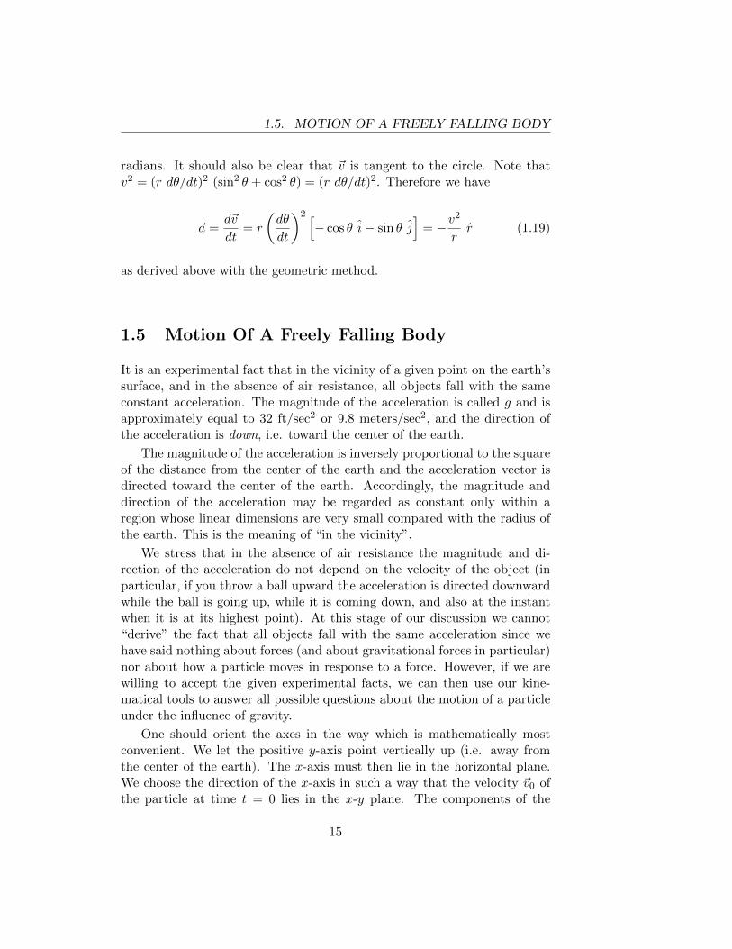
One should orient the axes in the way which is mathematically mostconvenient. We let the positive y-axis point vertically up (i.e. away fromthe center of the earth). The x-axis must then lie in the horizontal plane.We choose the direction of the x-axis in such a way that the velocity ~v0 ofthe particle at time t = 0 lies in the x-y plane. The components of the
15
1.5. MOTION OF A FREELY FALLING BODY
Figure 1.14: Initial velocity vector.
acceleration vector are ay = −g, ax = az = 0. Eqns. ( 1.11a- 1.11d) yield
vy = v0,y − gt (1.20a)
v2y = v2
0,y − 2g(y − y0) (1.20b)
y = y0 + 12(vy + v0,y)t (1.20c)
y = y0 + v0,yt− 12gt2 (1.20d)
vx = constant = v0,x (1.20e)
x = x0 + v0,xt (1.20f)
vz = constant = 0 z = constant = z0 (1.20g)
We shall always locate the origin in such a way that z0 = 0 and thusthe entire motion takes place in the x-y plane. Usually we locate the originat the initial position of the particle so that x0 = y0 = 0, but the aboveformulas do not assume this.
We can obtain the equation of the trajectory (the relation between yand x) by solving eqn.( 1.20f) for t and substituting the result into ( 1.20d).We find
y − y0 =v0,y
v0,x(x− x0)− 1
2g
(x− x0)2
v20,x
(1.21)
This is, of course, the equation of a parabola. If we locate our origin at theinitial position of the particle and if we specify the initial speed v0 and theangle θ between the initial velocity and the x-axis (thus v0x = v0 cos θ andv0y = v0 sin θ) then the equation of the trajectory is
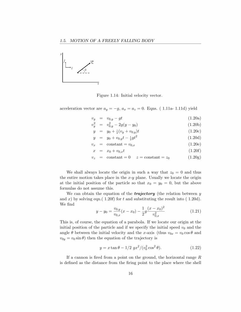
y = x tan θ − 1/2 gx2/(v20 cos2 θ). (1.22)
If a cannon is fired from a point on the ground, the horizontal range Ris defined as the distance from the firing point to the place where the shell
16
1.5. MOTION OF A FREELY FALLING BODY
Figure 1.15: Path of a parabolic trajectory.
hits the ground. If we set y = 0 in eqn.( 1.22) we find
0 = x
[tan θ − 1
2
gx
v20 cos2 θ
](1.23)
which has two roots, x = 0 and x = (2v20/g) sin θ cos θ = (v2
0/g) sin(2θ). Thefirst root is, of course, the firing point, and the second root tells where theshell lands, i.e.
R =v2
0
gsin(2θ). (1.24)
If we want to maximize the range for a given muzzle speed v0, we shouldfire at the angle which maximizes sin(2θ), i.e. θ = 45◦.
The simplest way to find the greatest height reached by a shell is to useeqn.( 1.20b), setting vy = 0. We find ymax − y0 = (v2
0/g) sin2 θ. We couldalso set dy/dx = 0 and find x = R/2, which is obvious when you considerthe symmetry of a parabola. We could then evaluate y when x = R/2.
Example 1.6 : Freely-falling motion after being thrown.
A stone is thrown with horizontal velocity 40 ft/sec and vertical (upward)velocity 20 ft/sec from a narrow bridge which is 200 ft above the water.
• How much time elapses before the stone hits the water?
• What is the vertical velocity of the stone just before it hits the water?
17
1.5. MOTION OF A FREELY FALLING BODY
• At what horizontal distance from the bridge does the stone hit thewater?
REMARK: It is NOT necessary to discuss the upward and downward partof the trajectory separately. The formulas of equations 1.20a - 1.20g applyto the entire trajectory.Solution:
(h = 200′ ) (1.20d)→ −h = v0,yt− 12gt2 ⇒
t =v0,y ±
√v2
0,y + 2gh
g
The positive root (4.215 sec) is the relevant one. The negative root is thetime at which the stone could have been projected upward from the riverwith a vertical velocity such that it would pass the bridge at t = 0 withan upward velocity of 20 ft/sec. Eqn.( 1.20a) gives the answer to (b); vy =20 − 32(4.215) = −114.88 (i.e. 114.88 ft/sec downward). Part (b) can alsobe answered directly (without calculating t) by Eqn.( 1.20b). Finally, forpart (c) we have x = 40(4.215) = 168.6 ft.
Example 1.7 : Freely-falling motion of a batted ball.
The bat strikes a ball at a point 4 ft above the ground. The velocity vectorof the batted ball initially is directed 20◦ above the horizontal.
1. What initial speed must the batted ball have in order to barely cleara 20 ft high wall located 350 ft from home plate?
2. There is a flat field on the other side of the wall. If the ball barelyclears the wall, at what horizontal distance from home plate will theball hit the ground?
Solution: We use the trajectory formula eqn.( 1.22), taking the origin atthe point where the bat strikes the ball. Note that tan 20◦ = 0.3640 andcos2 20◦ = 0.8830. Therefore
16 = 127.4− 18.120(350/v0)2 ⇒v0 = 141.2 ft/sec
18
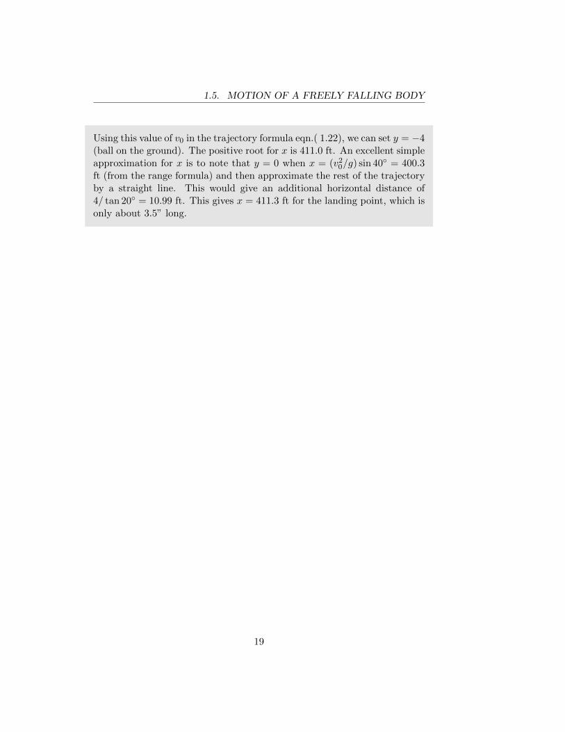
1.5. MOTION OF A FREELY FALLING BODY
Using this value of v0 in the trajectory formula eqn.( 1.22), we can set y = −4(ball on the ground). The positive root for x is 411.0 ft. An excellent simpleapproximation for x is to note that y = 0 when x = (v2
0/g) sin 40◦ = 400.3ft (from the range formula) and then approximate the rest of the trajectoryby a straight line. This would give an additional horizontal distance of4/ tan 20◦ = 10.99 ft. This gives x = 411.3 ft for the landing point, which isonly about 3.5” long.
19
1.6. KINEMATICS PROBLEMS
1.6 Kinematics Problems
1.6.1 One-Dimensional Motion
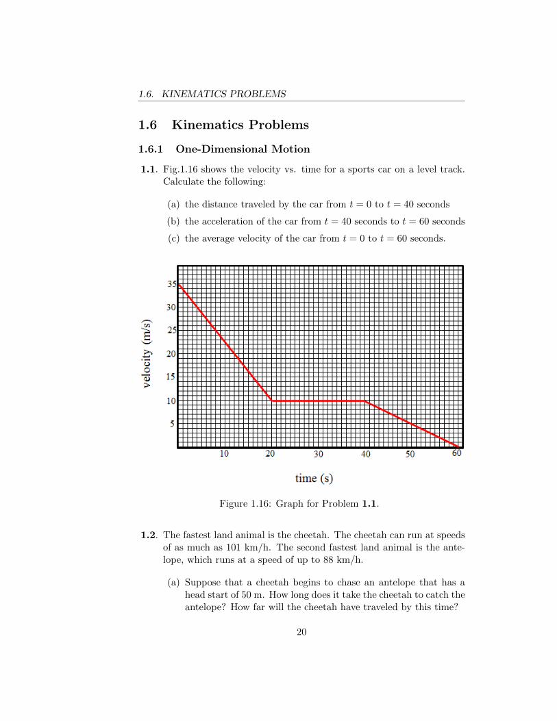
1.1. Fig.1.16 shows the velocity vs. time for a sports car on a level track.Calculate the following:
(a) the distance traveled by the car from t = 0 to t = 40 seconds
(b) the acceleration of the car from t = 40 seconds to t = 60 seconds
(c) the average velocity of the car from t = 0 to t = 60 seconds.
Figure 1.16: Graph for Problem 1.1.
1.2. The fastest land animal is the cheetah. The cheetah can run at speedsof as much as 101 km/h. The second fastest land animal is the ante-lope, which runs at a speed of up to 88 km/h.
(a) Suppose that a cheetah begins to chase an antelope that has ahead start of 50 m. How long does it take the cheetah to catch theantelope? How far will the cheetah have traveled by this time?
20
1.6. KINEMATICS PROBLEMS
(b) The cheetah can maintain its top speed for about 20 secondsbefore needing to rest. The antelope can continue at its top speedfor a considerably longer time. What is the maximum head startthe cheetah can allow the antelope and still be able to catch it?
1.3. A window is 3.00 m high. A ball is thrown vertically from the streetand, while going upward, passes the top of the window 0.400 s after itpasses the bottom of the window. Calculate
(a) the maximum height above the top of the window which the ballwill reach
(b) the time interval between the two instants when the ball passesthe top of the window.
1.4. An elevator is accelerating upward with acceleration A. A compressedspring on the floor of the elevator projects a ball upward with velocityv0 relative to the floor. Calculate the maximum height above the floorwhich the ball reaches.
1.5. A passageway in an air terminal is 200 meters long. Part of the pas-sageway contains a moving walkway (whose velocity is 2 m/s), andpassengers have a choice of using the moving walkway or walking nextto it. The length of the walkway is less than 200m. Two girls, Alisonand Miriam decide to have a race from the beginning to the end of thepassageway. Alison can run at a speed of 7 m/s but is not allowed touse the moving walkway. Miriam can run at 6 m/s and can use thewalkway (on which she runs, in violation of airport rules). The resultof the race through the passageway is a tie.
(a) How long is the walkway?
(b) They race again, traversing the passageway in the opposite di-rection from the moving walkway. This time Miriam does notset foot on the walkway and Alison must use the walkway. Whowins?
1.6.2 Two and Three Dimensional Motion
1.6. The position of a particle as a function of time is given by
~r = [(2t2 − 7t)i− t2j] m.
Find:
21
1.6. KINEMATICS PROBLEMS
(a) its velocity at t = 2 s.
(b) its acceleration at t = 5 s.
(c) its average velocity between t = 1 s and t = 3 s.
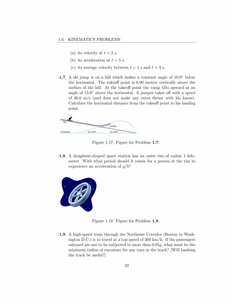
1.7. A ski jump is on a hill which makes a constant angle of 10.0◦ belowthe horizontal. The takeoff point is 6.00 meters vertically above thesurface of the hill. At the takeoff point the ramp tilts upward at anangle of 15.0◦ above the horizontal. A jumper takes off with a speedof 30.0 m/s (and does not make any extra thrust with his knees).Calculate the horizontal distance from the takeoff point to his landingpoint.
θ1 = 10.0°
θ2 = 15.0°
hill
jump
Θ1=10.0° Θ2=15.0°
6.00m
Horizontal
Figure 1.17: Figure for Problem 1.7.
1.8. A doughnut-shaped space station has an outer rim of radius 1 kilo-meter. With what period should it rotate for a person at the rim toexperience an acceleration of g/5?
Figure 1.18: Figure for Problem 1.8.
1.9. A high-speed train through the Northeast Corridor (Boston to Wash-ington D.C.) is to travel at a top speed of 300 km/h. If the passengersonboard are not to be subjected to more than 0.05g, what must be theminimum radius of curvature for any turn in the track? [Will bankingthe track be useful?]
22
1.6. KINEMATICS PROBLEMS
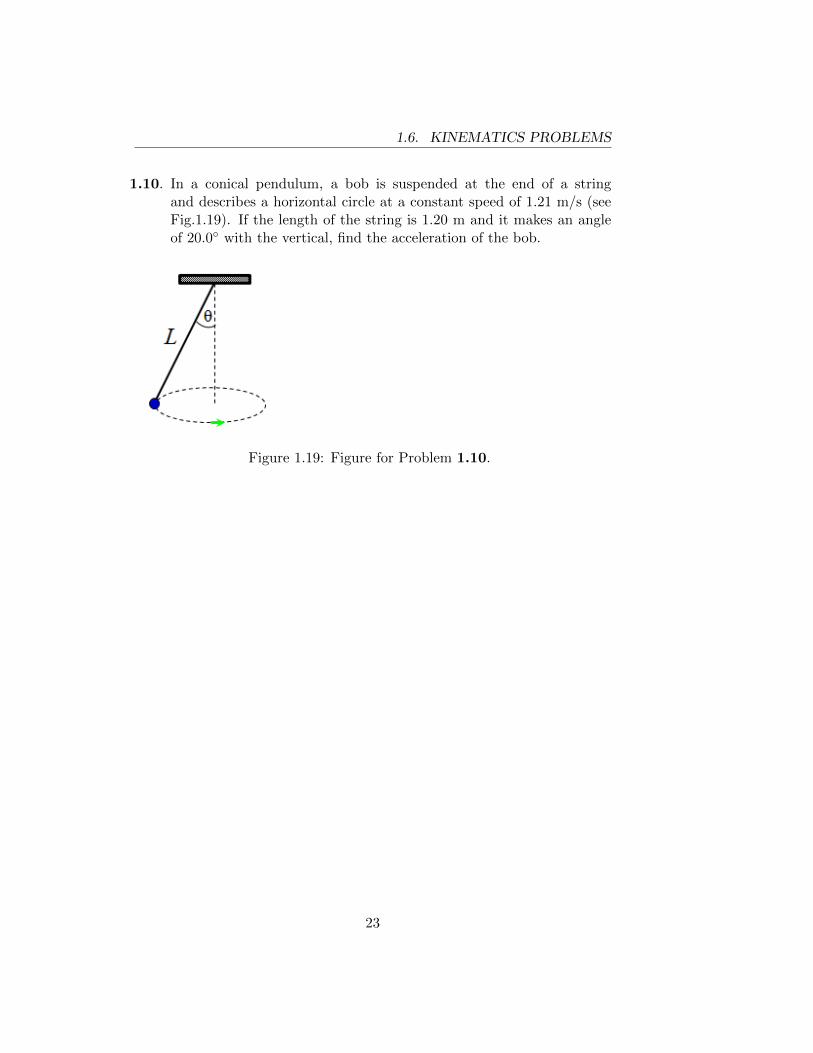
1.10. In a conical pendulum, a bob is suspended at the end of a stringand describes a horizontal circle at a constant speed of 1.21 m/s (seeFig.1.19). If the length of the string is 1.20 m and it makes an angleof 20.0◦ with the vertical, find the acceleration of the bob.
Figure 1.19: Figure for Problem 1.10.
23
1.6. KINEMATICS PROBLEMS
24
Chapter 2
NEWTON’S FIRST ANDTHIRD LAWS: STATICSOF PARTICLES
Perhaps the most appealing feature of classical mechanics is its logical econ-omy. Everything is derived from Newton’s three laws of motion. [Well,almost everything. One must also know something about the forces whichare acting.] It is necessary of course, to understand quite clearly what thelaws assert, and to acquire some experience in applying the laws to specificsituations.
We are concerned here with the first and third laws. The second law willbe discussed in the next chapter. Time spent in thinking about the meaningof these laws is (to put it mildly) not wasted.
2.1 Newton’s First Law; Forces
The first law, in Newton’s own words is: ”Every body perseveres in its stateof resting, or uniformly moving in a right line, unless it is compelled tochange that state by forces impressed upon it.”[New] In modern language,the first law states that the velocity of a body is constant if and only ifthere are no forces acting on the body or if the (vector) sum of the forcesacting on the body is zero. Note that when we say the velocity is constant,we mean that both the magnitude and direction of the velocity vector areconstant. In this statement we assume that all parts of the body have thesame velocity. Otherwise, at this early point in the discussion we don’t know
25
2.1. NEWTON’S FIRST LAW; FORCES
what we mean by “the velocity of a body”.Two questions immediately arise:
(a). What do we mean by a force?
(b). With respect to what set of axes is the first law true? (Note thata body at rest or moving with constant velocity as measured withrespect to one set of axes may be accelerating with respect to anotherset of axes.)
The answer to (a) and (b) are related. In fact, if we are willing tointroduce a sufficiently complicated notion of force, the first law will betrue with respect to every set of axes and says nothing. The “sufficientlycomplicated notion of force” would involve postulating that whenever wesee the velocity of a particle changing a force is acting on the particle evenif we cannot see the source of the force.
We shall insist on giving the word “force” a very restricted meaningwhich corresponds closely to the way the word is used in everyday language.We define a force as the push or pull exerted by one piece of matter onanother piece of matter. This definition is not quantitative (a quantitativemeasure of force will be introduced shortly) but emphasizes the fact thatwe are entitled to speak of a “force” only when we can identify the pieceof matter which is exerting the force and the piece of matter on which theforce is being exerted.
Some simple examples will illustrate what we mean and do not meanwhen we use the word “force”.
• As a stone falls toward the earth we observe that its velocity changesand we say that the earth is pulling on the stone. This pull (whichwe call the gravitational force exerted by the earth on the stone) isan acceptable use of the term “force” because we can see the piece ofmatter (the earth) which is exerting it. We have, of course, learned tolive with the idea that one piece of matter can exert a force on anotherpiece of matter without directly touching it.
• Consider a woman sitting in a moving railroad car. The earth is pullingdown on her. The seat on which she is sitting is exerting an upwardforce on her; if there are coil springs in the seat, this upward force isexerted by the springs, which are compressed.1 If the car accelerates
1Every seat has “springs” in it, but the springs may be very stiff. When you sit ona wooden bench, you sink slightly into the bench, compressing the wood until it exertsan upward force on you which is equal in magnitude but opposite in direction to thedownward pull exerted by the earth on you.
26
2.1. NEWTON’S FIRST LAW; FORCES
in the forward direction, the seat exerts an additional force on thewoman; this force is directed forward and is exerted by the back ofthe seat. Examination of the coil springs (or foam rubber) in theback of the seat will show that they are compressed during the periodwhen the train is accelerating. While the train is accelerating, thewoman has the feeling that something is pushing her back into herseat. Nevertheless, we do not acknowledge that there is any forcepushing the woman toward the back of the car since we cannot pointto any piece of matter which is exerting such a force on the woman.(If the car had a rear window and if we looked out that window andsaw a huge piece of matter as large as a planet behind the car, then wecould say that the gravitational force exerted by the planet is pullingthe woman toward the rear. But of course we don’t see this.)
If the floor of the car is very smooth, and if a box is resting on the floor,the box will start sliding toward the rear as the car accelerates. If wemeasure position and velocity in terms of axes which are attached tothe car, we will say that the box is accelerating toward the rear of thecar. Nevertheless we do not say that there is a force pushing the boxtoward the rear since we cannot point to the piece of matter whichexerts the force. Thus, with our restricted notion of force, Newton’sfirst law is not true if we use axes which are attached to the acceler-ating car. On the other hand, if we use axes attached to the ground,Newton’s first law is true. With respect to the latter axes the velocityof the box does not change; this is consistent with the statement thatthere is no force on the box.
We shall see that the relatively simple notion of “force” which we havedefined is quite sufficient for our purposes. Many forces are encounteredin everyday life, but if we look closely enough they can all be explained interms of the gravitational attraction exerted by one piece of matter (usu-ally the earth) on another, and the electric and magnetic forces exerted byone charged body on another. We shall frequently refer to the “contact”forces exerted by one body on another when their surfaces are touching.These “contact” forces can, in general, have a component perpendicular tothe surface and a component parallel to the surface; the two componentsare called, respectively, the normal force and the frictional force. If weexamine the microscopic origin of these forces, we find that they are electricforces between the surface molecules (or atoms) of one body and the sur-face molecules of the other body. Even though the molecules have no netcharge, each molecule contains both positive and negative charges; when
27
2.2. INERTIAL FRAMES
two molecules are close enough, the forces among the various charges donot exactly cancel out and there is a net force. Fortunately, the applicationof Newton’s laws does not require a detailed microscopic understanding ofsuch things as contact forces; nevertheless we refuse to include any force onour list unless we are convinced that it can ultimately be explained in termsof gravitational, electric, and/or magnetic forces.2
2.2 Inertial Frames
Now that we know what we mean by a force, we can ask “With respect towhich axes is it true that a particle subject to no forces moves with constantvelocity?”, i.e. with respect to which axes is Newton’s first law true? Aset of axes is frequently called a “frame of reference”, and those axes withrespect to which Newton’s first law is true are called inertial frames.
It is important to note that, as a consequence of Newton’s first law, thereis more than one inertial frame. If a set of axes XY Z are an inertial frame,and if another set of axes X ′Y ′Z ′ are moving with constant velocity andnot rotating with respect to XY Z, then X ′Y ′Z ′ are also an inertial frame.This follows from the fact that a particle which has constant velocity withrespect to the XY Z axes will also have a constant velocity with respect tothe X ′Y ′Z ′ axes.
We have already seen that axes attached to an accelerating railroad carare not an inertial frame, but axes attached to the earth are an inertialframe. Actually, this is not quite true. For most purposes, axes attachedto the earth appear to be an inertial frame. However, due to the earth’srotation, these axes are rotating relative to the background of the distantstars. If you give a hockey puck a large velocity directed due south on aperfectly smooth ice rink in Philadelphia, it will not travel in a perfectlystraight line relative to axes scratched on the ice, but will curve slightly tothe west because of the earth’s rotation. This effect is important in navalgunnery and illustrates that axes attached to the earth are not a perfectinertial frame. A better, but less convenient, set of axes are axes which arenon-rotating with respect to the distant stars and whose origin moves withthe center of the earth.
Another phenomenon which demonstrates that axes attached to theearth’s surface are not a perfect inertial frame is the Foucault pendulum. A
2The fundamental particles which are the constituents of matter are subject to gravi-tational and electromagnetic forces, and also to two other forces, the strong and the weakforce. The latter two forces do not come to play in everyday observations.
28
2.2. INERTIAL FRAMES
plumb bob attached by a string to the ceiling of a building at the North orSouth Pole will oscillate in a plane which is non-rotating with respect to thedistant stars. The earth rotates relative to the plane of the pendulum.
Newton was principally interested in calculating the orbits of the planets.For this purpose he used axes whose origin is at rest with respect to the sun,and which are non-rotating with respect to the distant stars. Thse are thebest inertial frame he could find and he seems to have regarded it as obviousthat these axes are at rest in “absolute space” which “without relation toanything external, remains always similar and immovable”. Kepler observedthat, relative to these axes, the planets move in elliptical orbits and thatthe periodic times of the planets (i.e. the time required for the planet tomake one circuit of the sun) are proportional to the 3/2 power of the semi-major axis of the ellipse. Newton used his laws of mechanics, plus his law ofuniversal gravitation (which gave a quantitative formula for the force exertedby the sun on the planets) to explain Kepler’s observations, assuming thatthe axes in question are an inertial frame or a close approximation thereto.Furthermore, he was able to calculate the orbit of Halley’s comet with greataccuracy.
Most (perhaps all) physicists today would say that the notion of “ab-solute space” is elusive or meaningless, and that the inertial frames arephysically defined by the influence of distant matter. Ordinarily, when weenumerate the forces acting on a body we include only the forces exerted onit by other bodies which are fairly close to it; e.g. if the body is a planet wetake account of the gravitational force which the sun exerts on the planetbut we do not explicitly take account of the force which the distant starsexert on the planet (nor do we really know how to calculate that force).Nevertheless, the effect of the distant stars cannot be ignored since they de-termine which are the inertial frames, i.e. they single out the preferred axeswith respect to which Newton’s laws are true. The important characteristicof axes attached to the sun is not that they are at rest in absolute space,but that they are freely falling under the gravitational influence of all thematter outside the solar system.
In most of the homely examples which we shall discuss, axes attached tothe surface of the earth can be treated as an inertial frame. In discussion ofplanetary motion we shall use axes attached to the sun which do not rotaterelative to the distant stars.
29
2.3. QUANTITATIVE DEFINITION OF FORCE; STATICS OFPARTICLES
2.3 Quantitative Definition of Force; Statics of Par-ticles
Newton’s second law, which we shall discuss in the next chapter, states thatthe acceleration of a body is proportional to the total force acting on thebody. Some authors use this fact as the basis for a quantitative definitionof force. We propose to define “force” quantitatively before discussing thesecond law. Thus it will be clear that the second law is a statement aboutthe world and not just a definition of the word “force”. We shall then gainfamiliarity with the analysis of forces by studying a number of examples ofthe static equilibrium of particles.
As the unit of force we choose some elementary, reproducible push orpull. This could, for example, be exerted by a standard spring stretched bya standard amount at a standard temperature. Two units of force wouldthen be the force exerted by two such standard springs attached to the sameobject and pulling in the same direction (depending on the characteristicsof the spring this might or might not be the same as the force exerted by asingle spring stretched by twice the standard amount).
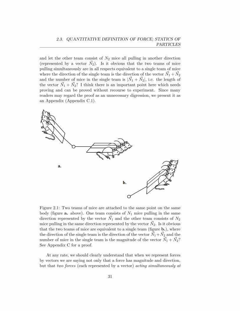
More whimsically, if we imagine that we have a supply of identical micewhich always pull as hard as they can, then the “mouse” can be used as theunit of force. One mouse pulling in a given direction can be represented byan arrow of unit length pointing in that direction. Three mice pulling inthe same direction can be represented by an arrow of length three pointingin that direction. The definition is easily extended to fractional numbersof mice; e.g. if it is found that seven squirrels pulling in a given directionproduce exactly the same effect as nineteen mice pulling in that direction,then we represent the force exerted by one squirrel by an arrow of length19/7 in the appropriate direction.3 Thus any push or pull in a definitedirection can be represented by an arrow in that direction, the length of thearrow being the number of mice required to perfectly mimic the given pushor pull.
Since we have established a procedure for representing forces by arrowswhich have lengths and directions, it seems almost obvious that forces haveall the properties of vectors. In particular, suppose two teams of mice areattached to the same point on the same body. Let one team consist ofN1 mice all pulling in the same direction (represented by a vector ~N1),
3Since any irrational number is the limit of a sequence of rational numbers, the defi-nition is readily extended to forces which are equivalent to an irrational number of mice(which is not the same as a number of irrational mice!)
30
2.3. QUANTITATIVE DEFINITION OF FORCE; STATICS OFPARTICLES
and let the other team consist of N2 mice all pulling in another direction(represented by a vector ~N2). Is it obvious that the two teams of micepulling simultaneously are in all respects equivalent to a single team of micewhere the direction of the single team is the direction of the vector ~N1 + ~N2
and the number of mice in the single team is | ~N1 + ~N2|, i.e. the length ofthe vector ~N1 + ~N2? I think there is an important point here which needsproving and can be proved without recourse to experiment. Since manyreaders may regard the proof as an unnecessary digression, we present it asan Appendix (Appendix C.1).
Figure 2.1: Two teams of mice are attached to the same point on the samebody (figure a. above). One team consists of N1 mice pulling in the samedirection represented by the vector ~N1 and the other team consists of N2
mice pulling in the same direction represented by the vector ~N2. Is it obviousthat the two teams of mice are equivalent to a single team (figure b.), wherethe direction of the single team is the direction of the vector ~N1 + ~N2 and thenumber of mice in the single team is the magnitude of the vector ~N1 + ~N2?See Appendix C for a proof.
At any rate, we should clearly understand that when we represent forcesby vectors we are saying not only that a force has magnitude and direction,but that two forces (each represented by a vector) acting simultaneously at
31
2.4. EXAMPLES OF STATIC EQUILIBRIUM OF PARTICLES
the same point are equivalent to a single force, represented by the vector sumof the two force vectors. It follows that when more than two forces act at apoint, they are equivalent to a single force, represented by the vector sumof the vectors representing the individual forces.
Now we can discuss the equilibrium of point masses. A “point mass” isa body so small that we measure only its location and ignore the fact thatdifferent parts of the body may have different velocities. We shall see shortlythat, as a consequence of Newton’s third law, Newton’s laws apply not onlyto point masses but to larger composite objects consisting of several or manypoint masses.
A body is said to be in equilibrium when it is at rest (not just for aninstant, but permanently or at least for a finite period of time4) or movingwith constant velocity. According to Newton’s first law, there is no force ona body in equilibrium.
The simplest example of equilibrium would be a particle in the outerreaches of the solar system, sufficiently far from the sun and the planetsso as to be subject to negligible gravitational forces. This example is notvery interesting since no forces act on the particle. The more interestingexamples of equilibrium, as encountered in everyday life, are situations inwhich the net (or “resultant”) force on a body is zero, but several forces areacting on the body; thus the equilibrium of the body results from the factthat the vector sum of all the forces acting on the body is zero.
2.4 Examples of Static Equilibrium of Particles
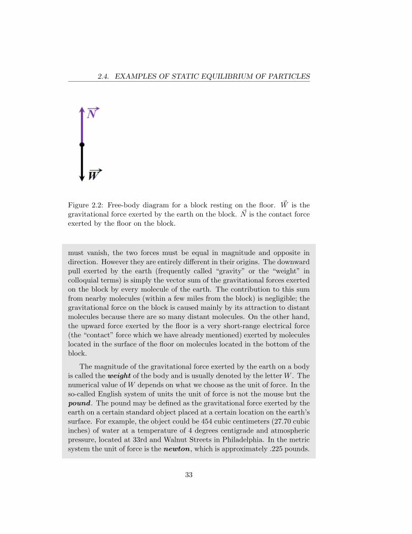
Example 2.1 : Static equilibrium of a block on the floor.
As a first example of equilibrium, we consider a block at rest on the floor.We assume here that the block can be treated as a “point mass” which obeysNewton’s first law. Even if the block is not very small we shall see shortlythat Newton’s third law justifies treating the block as a “point mass”.
Two forces act on the block: the earth pulls downward on the block andthe floor pushes upward on the block. Since the total force on the block
4If a ball is thrown vertically upward, it will be instantaneously at rest at the momentwhen it reaches its highest point. The ball is not in equilibrium at that instant since itdoes not remain at rest for a finite time and the net force on the ball is not zero. On theother hand, a ball lying on the ground is in equilibrium.
32
2.4. EXAMPLES OF STATIC EQUILIBRIUM OF PARTICLES
Figure 2.2: Free-body diagram for a block resting on the floor. ~W is thegravitational force exerted by the earth on the block. ~N is the contact forceexerted by the floor on the block.
must vanish, the two forces must be equal in magnitude and opposite indirection. However they are entirely different in their origins. The downwardpull exerted by the earth (frequently called “gravity” or the “weight” incolloquial terms) is simply the vector sum of the gravitational forces exertedon the block by every molecule of the earth. The contribution to this sumfrom nearby molecules (within a few miles from the block) is negligible; thegravitational force on the block is caused mainly by its attraction to distantmolecules because there are so many distant molecules. On the other hand,the upward force exerted by the floor is a very short-range electrical force(the “contact” force which we have already mentioned) exerted by moleculeslocated in the surface of the floor on molecules located in the bottom of theblock.
The magnitude of the gravitational force exerted by the earth on a bodyis called the weight of the body and is usually denoted by the letter W . Thenumerical value of W depends on what we choose as the unit of force. In theso-called English system of units the unit of force is not the mouse but thepound . The pound may be defined as the gravitational force exerted by theearth on a certain standard object placed at a certain location on the earth’ssurface. For example, the object could be 454 cubic centimeters (27.70 cubicinches) of water at a temperature of 4 degrees centigrade and atmosphericpressure, located at 33rd and Walnut Streets in Philadelphia. In the metricsystem the unit of force is the newton , which is approximately .225 pounds.
33
2.4. EXAMPLES OF STATIC EQUILIBRIUM OF PARTICLES
[Note: the Google web site will do many kinds of common conversions foryou. There’s no need to memorize specific conversion factors. Nevertheless,it is useful to know (at least approximately) common conversion factors,e.g. meters↔ feet, centimeters↔ inches, kilowatts↔ horsepower, etc.] Weoften abbreviate the newton unit as N. It is often useful to draw a free-body diagram in which each of the forces acting on a body is representedby a vector. Usually all of the vectors are drawn originating from a commonorigin. If the body is in equilibrium, the vector sum of all the forces in thefree-body diagram is zero. In the present example, the free-body diagramis very simple (Fig.2.2) and adds nothing to our verbal description. In thefollowing more interesting examples, quantitative conclusions can be drawnfrom the free-body diagram.
Figure 2.3: The block is held in place by a force applied parallel to theincline. The free-body diagram includes three forces.
Figure 2.4: See example 2.2b. In this case the block is held in place by ahorizontal applied force.
34
2.4. EXAMPLES OF STATIC EQUILIBRIUM OF PARTICLES
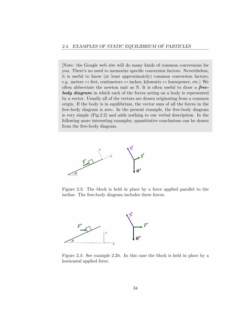
Example 2.2 : A block in equilibrium on a frictionless incline.
Consider a block in equilibrium on a smooth inclined plane. The earth pullsdownward on the block and the plane exerts a contact force on the block in adirection normal (perpendicular) to the plane. Evidently, a third force mustbe applied to the block if it is to be in equilibrium. Experience tells us thatthe direction of this third force is not uniquely determined. For example,the block can be kept in equilibrium by an appropriate force applied parallelto the plane in the uphill direction (Fig.2.3) or by an appropriate horizontalforce (Fig.2.4). In fact, there is a continuum of possible directions for thethird force. If the block is to be in equilibrium, the third force must havethe appropriate magnitude. This depends on the direction in which it isapplied.
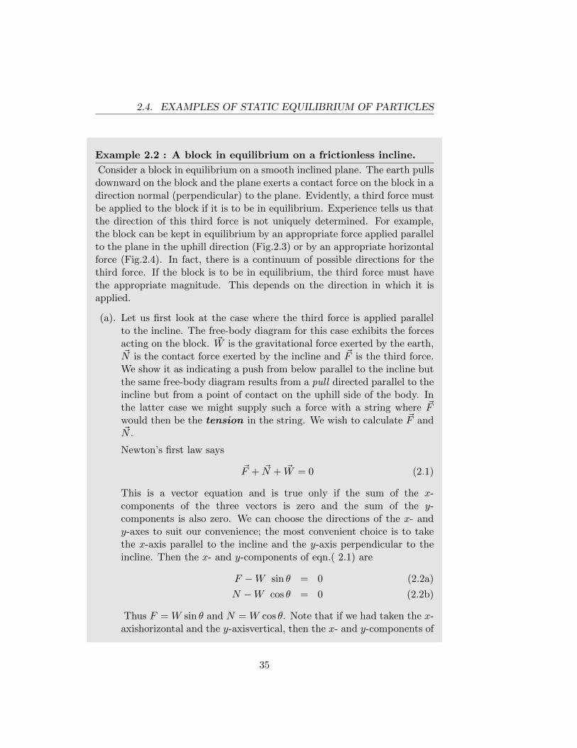
(a). Let us first look at the case where the third force is applied parallelto the incline. The free-body diagram for this case exhibits the forcesacting on the block. ~W is the gravitational force exerted by the earth,~N is the contact force exerted by the incline and ~F is the third force.We show it as indicating a push from below parallel to the incline butthe same free-body diagram results from a pull directed parallel to theincline but from a point of contact on the uphill side of the body. Inthe latter case we might supply such a force with a string where ~Fwould then be the tension in the string. We wish to calculate ~F and~N .
Newton’s first law says
~F + ~N + ~W = 0 (2.1)
This is a vector equation and is true only if the sum of the x-components of the three vectors is zero and the sum of the y-components is also zero. We can choose the directions of the x- andy-axes to suit our convenience; the most convenient choice is to takethe x-axis parallel to the incline and the y-axis perpendicular to theincline. Then the x- and y-components of eqn.( 2.1) are
F −W sin θ = 0 (2.2a)
N −W cos θ = 0 (2.2b)
Thus F = W sin θ and N = W cos θ. Note that if we had taken the x-axishorizontal and the y-axisvertical, then the x- and y-components of
35
2.4. EXAMPLES OF STATIC EQUILIBRIUM OF PARTICLES
eqn.( 2.1) would be F cos θ−N sin θ = 0 and F sin θ+N cos θ−W = 0,which again yield F = W sin θ and N = W cos θ.
(b). If the third force is applied horizontally (we call it ~F again), the free-body diagram is shown in Fig.2.4. If we take the x-axis horizontal andthe y-axis vertical, the components of the vector equation ~F+ ~N+ ~W =0 are F −N sin θ = 0 and N cos θ −W = 0. Thus N = W/ cos θ andF = W tan θ. Note the different expressions for N in this case andthe previous one; note also that in this case F becomes infinite as θapproaches 90◦. Does this agree with your “physical intuition”?
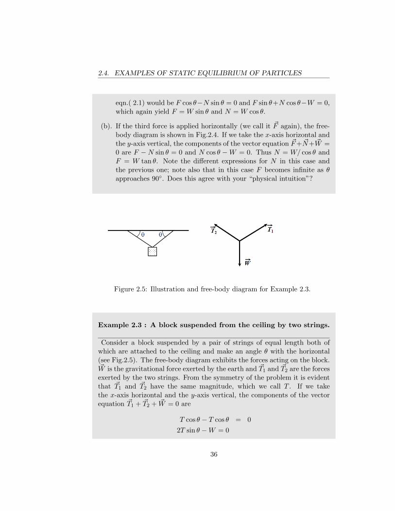
Figure 2.5: Illustration and free-body diagram for Example 2.3.
Example 2.3 : A block suspended from the ceiling by two strings.
Consider a block suspended by a pair of strings of equal length both ofwhich are attached to the ceiling and make an angle θ with the horizontal(see Fig.2.5). The free-body diagram exhibits the forces acting on the block.~W is the gravitational force exerted by the earth and ~T1 and ~T2 are the forcesexerted by the two strings. From the symmetry of the problem it is evidentthat ~T1 and ~T2 have the same magnitude, which we call T . If we takethe x-axis horizontal and the y-axis vertical, the components of the vectorequation ~T1 + ~T2 + ~W = 0 are
T cos θ − T cos θ = 0
2T sin θ −W = 0
36
2.4. EXAMPLES OF STATIC EQUILIBRIUM OF PARTICLES
The first of these equations tells us nothing but merely confirms our assump-tion that the tensions in both strings are equal. The second tells us that therequired tension in the strings is T = W/(2 sin θ).
Note that T becomes very large when θ is very small (in fact T →∞ asθ → 0). Thus we see that a rather modest sideways force applied to a tautwire can break the wire. However, if we apply a sideways force to the centerof a taut nylon rope, the rope will stretch; since θ does not remain small,the tension in the rope will not become very large.
Figure 2.6: Illustration and free-body diagram for Example 2.4.
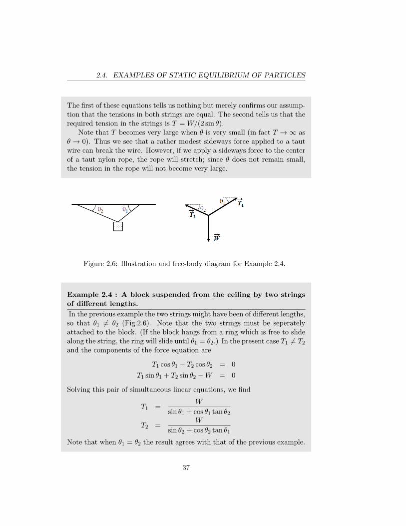
Example 2.4 : A block suspended from the ceiling by two stringsof different lengths.
In the previous example the two strings might have been of different lengths,so that θ1 6= θ2 (Fig.2.6). Note that the two strings must be seperatelyattached to the block. (If the block hangs from a ring which is free to slidealong the string, the ring will slide until θ1 = θ2.) In the present case T1 6= T2
and the components of the force equation are
T1 cos θ1 − T2 cos θ2 = 0
T1 sin θ1 + T2 sin θ2 −W = 0
Solving this pair of simultaneous linear equations, we find
T1 =W
sin θ1 + cos θ1 tan θ2
T2 =W
sin θ2 + cos θ2 tan θ1
Note that when θ1 = θ2 the result agrees with that of the previous example.
37
2.5. NEWTON’S THIRD LAW
2.5 Newton’s Third Law
We have not yet considered the static equilibrium of systems which consistof several bodies, which may exert forces on each other. In order to discusssuch systems we must introduce a very important property of forces whichhas not yet been mentioned and cannot be deduced from anything whichhas been said up to this point. Newton’s statement of this property is:
“To every action there is always opposed an equal reaction; or,the mutual actions of two bodies upon each other are alwaysequal, and directed to contrary points.”
This is called Newton’s Third Law of Motion . Newton goes on togive some examples of the third law:
“If you press a stone with your finger, the finger is also pressedby the stone. If a horse draws a stone tied to a rope, the horse(if I may say so) will be equally drawn back towards the stone...”
In modern language, the third law can be stated as follows:
”For every force which A exerts on B, B exerts an equal andoppositely directed force on A.”
These forces are called an action-reaction pair.The third law has very important consequences and it is essential to
understand exactly what the third law asserts. Let us look again at Example2.1 (the block on the floor). There are two forces acting on the block: ~W (thegravitational force exerted by the earth) and ~N (the contact force exerted bythe floor). The reaction to ~W is the gravitational force exerted on the earchby the block. This force is represented by the vector − ~W , i.e. the magnitudeof the gravitational force exerted by the block on the earth is W but thedirection of this force is upward. The reaction to ~N is the contact forceexerted by the block on the floor. As we have previously noted, this force isa very short-range electrical force. This force has the same magnitude as ~Nbut opposite direction (downward), and is represented by the vector − ~N .
A common misconception is that ~W and ~N are an action-reaction pair.Note that the two forces in an action-reaction pair do not act on the samebody (one is exerted by A on B while the other is exerted by B on A). Since~W and ~N act on the same body (the block), they cannot be an action-reaction pair. Furthermore, the two forces in an action-reaction pair are
38
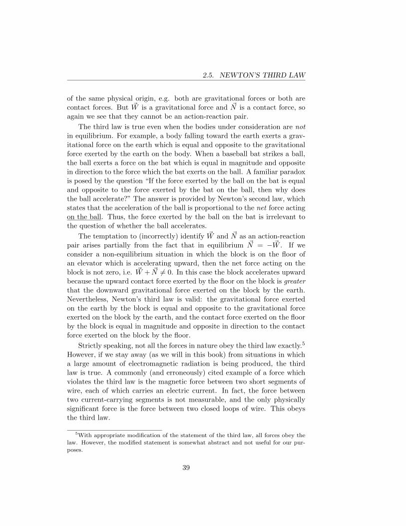
2.5. NEWTON’S THIRD LAW
of the same physical origin, e.g. both are gravitational forces or both arecontact forces. But ~W is a gravitational force and ~N is a contact force, soagain we see that they cannot be an action-reaction pair.
The third law is true even when the bodies under consideration are notin equilibrium. For example, a body falling toward the earth exerts a grav-itational force on the earth which is equal and opposite to the gravitationalforce exerted by the earth on the body. When a baseball bat strikes a ball,the ball exerts a force on the bat which is equal in magnitude and oppositein direction to the force which the bat exerts on the ball. A familiar paradoxis posed by the question “If the force exerted by the ball on the bat is equaland opposite to the force exerted by the bat on the ball, then why doesthe ball accelerate?” The answer is provided by Newton’s second law, whichstates that the acceleration of the ball is proportional to the net force actingon the ball. Thus, the force exerted by the ball on the bat is irrelevant tothe question of whether the ball accelerates.
The temptation to (incorrectly) identify ~W and ~N as an action-reactionpair arises partially from the fact that in equilibrium ~N = − ~W . If weconsider a non-equilibrium situation in which the block is on the floor ofan elevator which is accelerating upward, then the net force acting on theblock is not zero, i.e. ~W + ~N 6= 0. In this case the block accelerates upwardbecause the upward contact force exerted by the floor on the block is greaterthat the downward gravitational force exerted on the block by the earth.Nevertheless, Newton’s third law is valid: the gravitational force exertedon the earth by the block is equal and opposite to the gravitational forceexerted on the block by the earth, and the contact force exerted on the floorby the block is equal in magnitude and opposite in direction to the contactforce exerted on the block by the floor.
Strictly speaking, not all the forces in nature obey the third law exactly.5
However, if we stay away (as we will in this book) from situations in whicha large amount of electromagnetic radiation is being produced, the thirdlaw is true. A commonly (and erroneously) cited example of a force whichviolates the third law is the magnetic force between two short segments ofwire, each of which carries an electric current. In fact, the force betweentwo current-carrying segments is not measurable, and the only physicallysignificant force is the force between two closed loops of wire. This obeysthe third law.
5With appropriate modification of the statement of the third law, all forces obey thelaw. However, the modified statement is somewhat abstract and not useful for our pur-poses.
39
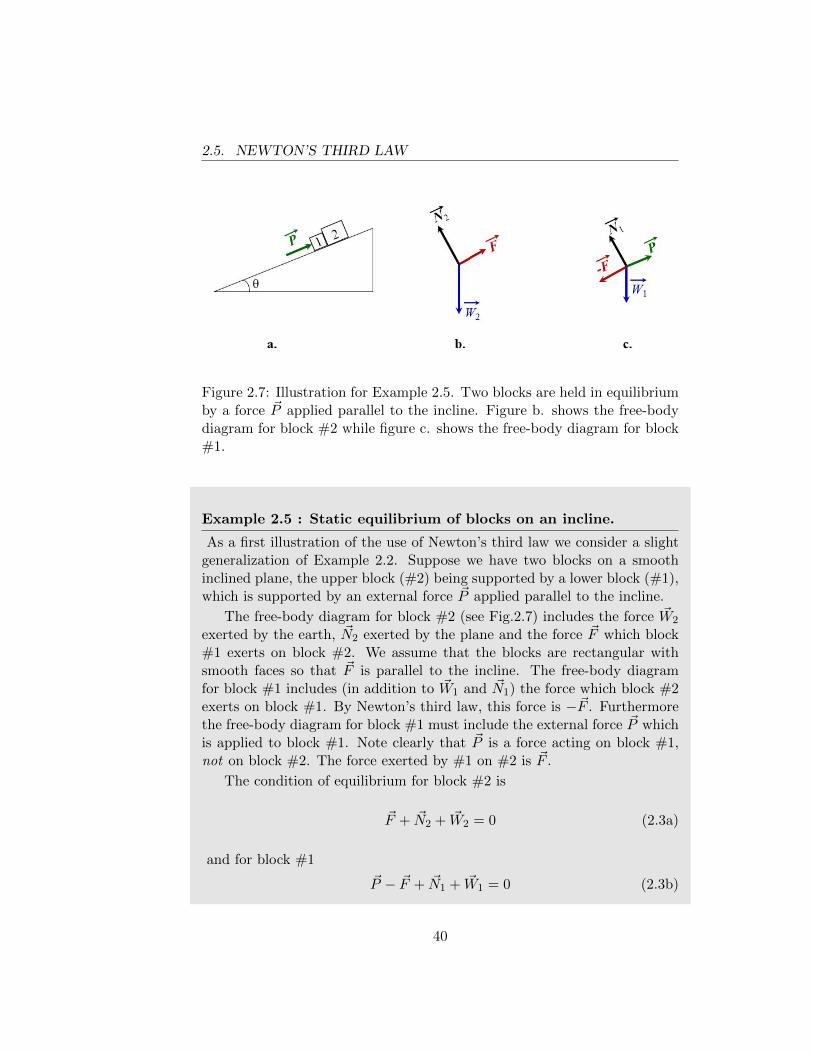
2.5. NEWTON’S THIRD LAW
Figure 2.7: Illustration for Example 2.5. Two blocks are held in equilibriumby a force ~P applied parallel to the incline. Figure b. shows the free-bodydiagram for block #2 while figure c. shows the free-body diagram for block#1.
Example 2.5 : Static equilibrium of blocks on an incline.
As a first illustration of the use of Newton’s third law we consider a slightgeneralization of Example 2.2. Suppose we have two blocks on a smoothinclined plane, the upper block (#2) being supported by a lower block (#1),which is supported by an external force ~P applied parallel to the incline.
The free-body diagram for block #2 (see Fig.2.7) includes the force ~W2
exerted by the earth, ~N2 exerted by the plane and the force ~F which block#1 exerts on block #2. We assume that the blocks are rectangular withsmooth faces so that ~F is parallel to the incline. The free-body diagramfor block #1 includes (in addition to ~W1 and ~N1) the force which block #2exerts on block #1. By Newton’s third law, this force is −~F . Furthermorethe free-body diagram for block #1 must include the external force ~P whichis applied to block #1. Note clearly that ~P is a force acting on block #1,not on block #2. The force exerted by #1 on #2 is ~F .
The condition of equilibrium for block #2 is
~F + ~N2 + ~W2 = 0 (2.3a)
and for block #1
~P − ~F + ~N1 + ~W1 = 0 (2.3b)
40
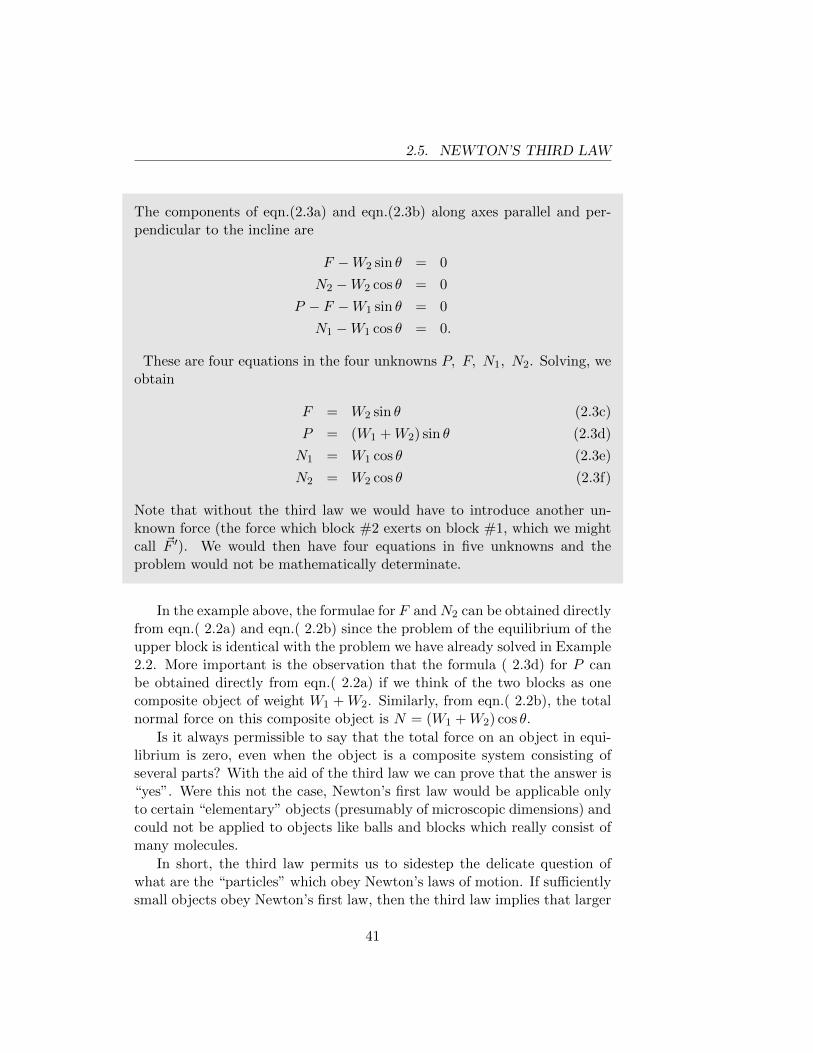
2.5. NEWTON’S THIRD LAW
The components of eqn.(2.3a) and eqn.(2.3b) along axes parallel and per-pendicular to the incline are
F −W2 sin θ = 0
N2 −W2 cos θ = 0
P − F −W1 sin θ = 0
N1 −W1 cos θ = 0.
These are four equations in the four unknowns P, F, N1, N2. Solving, weobtain
F = W2 sin θ (2.3c)
P = (W1 +W2) sin θ (2.3d)
N1 = W1 cos θ (2.3e)
N2 = W2 cos θ (2.3f)
Note that without the third law we would have to introduce another un-known force (the force which block #2 exerts on block #1, which we mightcall ~F ′). We would then have four equations in five unknowns and theproblem would not be mathematically determinate.
In the example above, the formulae for F and N2 can be obtained directlyfrom eqn.( 2.2a) and eqn.( 2.2b) since the problem of the equilibrium of theupper block is identical with the problem we have already solved in Example2.2. More important is the observation that the formula ( 2.3d) for P canbe obtained directly from eqn.( 2.2a) if we think of the two blocks as onecomposite object of weight W1 +W2. Similarly, from eqn.( 2.2b), the totalnormal force on this composite object is N = (W1 +W2) cos θ.
Is it always permissible to say that the total force on an object in equi-librium is zero, even when the object is a composite system consisting ofseveral parts? With the aid of the third law we can prove that the answer is“yes”. Were this not the case, Newton’s first law would be applicable onlyto certain “elementary” objects (presumably of microscopic dimensions) andcould not be applied to objects like balls and blocks which really consist ofmany molecules.
In short, the third law permits us to sidestep the delicate question ofwhat are the “particles” which obey Newton’s laws of motion. If sufficientlysmall objects obey Newton’s first law, then the third law implies that larger
41
2.5. NEWTON’S THIRD LAW
objects will also obey the first law.6
We define a system as any collection of particles (a particle is an objectsufficiently small that it obeys Newton’s laws). The particles are enumeratedby an index i = 1, 2, ..., N . We say that the system is in equilibrium whenevery particle of the system is in equilibrium (i.e. at rest or moving withconstant velocity).
If ~Fi is the total force acting on the ith particle, then in equilibrium~Fi = 0 for every i, and thus
N∑i=1
~Fi = 0
We can write ~Fi as the sum of two terms
~Fi = ~Fi, ext +N∑
j=1//j 6=i
~fji (2.4)
where ~Fi, ext is the external force on the ith particle (i.e. the force exertedon the ith particle by particles which are not included in the system) and~fji is the force exerted by the jth particle on the ith particle.7 Thus the
equation∑
i~Fi = 0 becomes∑
i
~Fi, ext +∑i
∑j
~fji = 0.
But the terms in the double sum cancel each other in pairs; for example,the sum includes both ~f21 and ~f12, which are an action-reaction pair andtherefore add vectorially to zero. Thus the double sum vanishes (i.e. thetotal internal force vanishes; this is frequently summarized by the statementthat “you can’t lift yourself by your own bootstraps”) and we have∑
i
~Fi, ext = 0. (2.5)
Therefore, if a system of particles is in equilibrium, the total external forceon the system must vanish.
6The third law also permits the second law to be applied to large “composite” objectsas we shall shortly see.
7We assume that a particle cannot exert any force on itself, i.e. ~fii = 0. Strictlyspeaking, this follows from Newton’s third law which says ~fii = −~fii since the action andreaction would be identical in the case of a self-force.
42
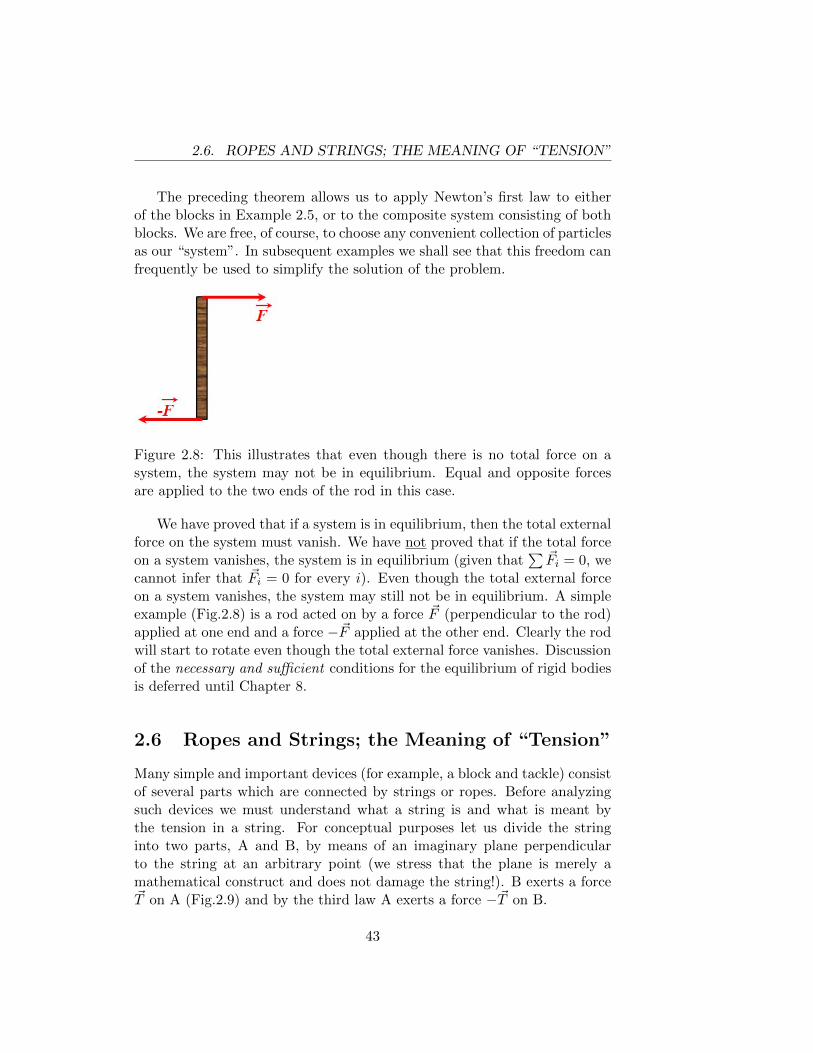
2.6. ROPES AND STRINGS; THE MEANING OF “TENSION”
The preceding theorem allows us to apply Newton’s first law to eitherof the blocks in Example 2.5, or to the composite system consisting of bothblocks. We are free, of course, to choose any convenient collection of particlesas our “system”. In subsequent examples we shall see that this freedom canfrequently be used to simplify the solution of the problem.
Figure 2.8: This illustrates that even though there is no total force on asystem, the system may not be in equilibrium. Equal and opposite forcesare applied to the two ends of the rod in this case.
We have proved that if a system is in equilibrium, then the total externalforce on the system must vanish. We have not proved that if the total forceon a system vanishes, the system is in equilibrium (given that
∑ ~Fi = 0, wecannot infer that ~Fi = 0 for every i). Even though the total external forceon a system vanishes, the system may still not be in equilibrium. A simpleexample (Fig.2.8) is a rod acted on by a force ~F (perpendicular to the rod)applied at one end and a force −~F applied at the other end. Clearly the rodwill start to rotate even though the total external force vanishes. Discussionof the necessary and sufficient conditions for the equilibrium of rigid bodiesis deferred until Chapter 8.
2.6 Ropes and Strings; the Meaning of “Tension”
Many simple and important devices (for example, a block and tackle) consistof several parts which are connected by strings or ropes. Before analyzingsuch devices we must understand what a string is and what is meant bythe tension in a string. For conceptual purposes let us divide the stringinto two parts, A and B, by means of an imaginary plane perpendicularto the string at an arbitrary point (we stress that the plane is merely amathematical construct and does not damage the string!). B exerts a force~T on A (Fig.2.9) and by the third law A exerts a force −~T on B.
43
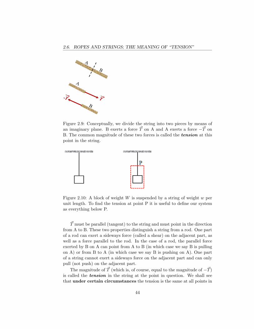
2.6. ROPES AND STRINGS; THE MEANING OF “TENSION”
Figure 2.9: Conceptually, we divide the string into two pieces by means ofan imaginary plane. B exerts a force ~T on A and A exerts a force −~T onB. The common magnitude of these two forces is called the tension at thispoint in the string.
Figure 2.10: A block of weight W is suspended by a string of weight w perunit length. To find the tension at point P it is useful to define our systemas everything below P.
~T must be parallel (tangent) to the string and must point in the directionfrom A to B. These two properties distinguish a string from a rod. One partof a rod can exert a sideways force (called a shear) on the adjacent part, aswell as a force parallel to the rod. In the case of a rod, the parallel forceexerted by B on A can point from A to B (in which case we say B is pullingon A) or from B to A (in which case we say B is pushing on A). One partof a string cannot exert a sideways force on the adjacent part and can onlypull (not push) on the adjacent part.
The magnitude of ~T (which is, of course, equal to the magnitude of −~T )is called the tension in the string at the point in question. We shall seethat under certain circumstances the tension is the same at all points in
44
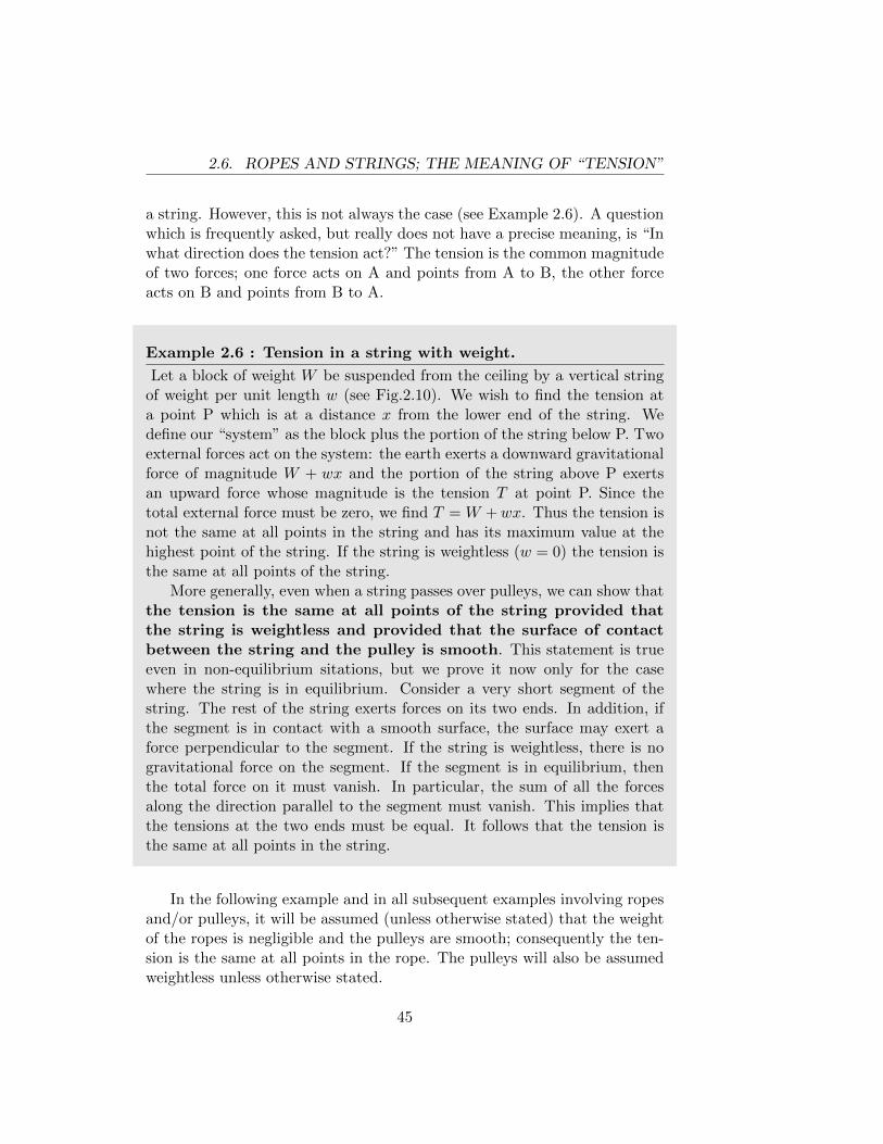
2.6. ROPES AND STRINGS; THE MEANING OF “TENSION”
a string. However, this is not always the case (see Example 2.6). A questionwhich is frequently asked, but really does not have a precise meaning, is “Inwhat direction does the tension act?” The tension is the common magnitudeof two forces; one force acts on A and points from A to B, the other forceacts on B and points from B to A.
Example 2.6 : Tension in a string with weight.
Let a block of weight W be suspended from the ceiling by a vertical stringof weight per unit length w (see Fig.2.10). We wish to find the tension ata point P which is at a distance x from the lower end of the string. Wedefine our “system” as the block plus the portion of the string below P. Twoexternal forces act on the system: the earth exerts a downward gravitationalforce of magnitude W + wx and the portion of the string above P exertsan upward force whose magnitude is the tension T at point P. Since thetotal external force must be zero, we find T = W +wx. Thus the tension isnot the same at all points in the string and has its maximum value at thehighest point of the string. If the string is weightless (w = 0) the tension isthe same at all points of the string.
More generally, even when a string passes over pulleys, we can show thatthe tension is the same at all points of the string provided thatthe string is weightless and provided that the surface of contactbetween the string and the pulley is smooth. This statement is trueeven in non-equilibrium sitations, but we prove it now only for the casewhere the string is in equilibrium. Consider a very short segment of thestring. The rest of the string exerts forces on its two ends. In addition, ifthe segment is in contact with a smooth surface, the surface may exert aforce perpendicular to the segment. If the string is weightless, there is nogravitational force on the segment. If the segment is in equilibrium, thenthe total force on it must vanish. In particular, the sum of all the forcesalong the direction parallel to the segment must vanish. This implies thatthe tensions at the two ends must be equal. It follows that the tension isthe same at all points in the string.
In the following example and in all subsequent examples involving ropesand/or pulleys, it will be assumed (unless otherwise stated) that the weightof the ropes is negligible and the pulleys are smooth; consequently the ten-sion is the same at all points in the rope. The pulleys will also be assumedweightless unless otherwise stated.
45
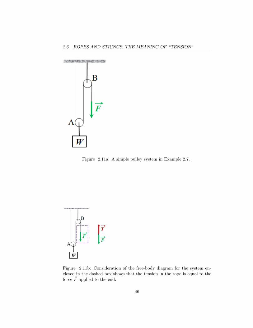
2.6. ROPES AND STRINGS; THE MEANING OF “TENSION”
Figure 2.11a: A simple pulley system in Example 2.7.
Figure 2.11b: Consideration of the free-body diagram for the system en-closed in the dashed box shows that the tension in the rope is equal to theforce ~F applied to the end.
46
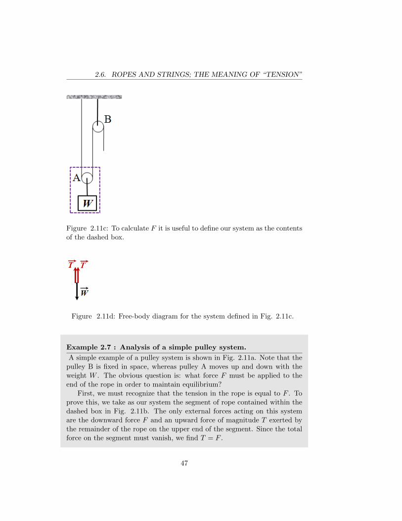
2.6. ROPES AND STRINGS; THE MEANING OF “TENSION”
Figure 2.11c: To calculate F it is useful to define our system as the contentsof the dashed box.
Figure 2.11d: Free-body diagram for the system defined in Fig. 2.11c.
Example 2.7 : Analysis of a simple pulley system.
A simple example of a pulley system is shown in Fig. 2.11a. Note that thepulley B is fixed in space, whereas pulley A moves up and down with theweight W . The obvious question is: what force F must be applied to theend of the rope in order to maintain equilibrium?
First, we must recognize that the tension in the rope is equal to F . Toprove this, we take as our system the segment of rope contained within thedashed box in Fig. 2.11b. The only external forces acting on this systemare the downward force F and an upward force of magnitude T exerted bythe remainder of the rope on the upper end of the segment. Since the totalforce on the segment must vanish, we find T = F .
47
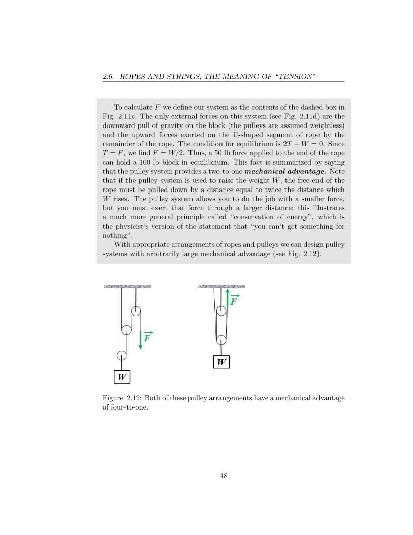
2.6. ROPES AND STRINGS; THE MEANING OF “TENSION”
To calculate F we define our system as the contents of the dashed box inFig. 2.11c. The only external forces on this system (see Fig. 2.11d) are thedownward pull of gravity on the block (the pulleys are assumed weightless)and the upward forces exerted on the U-shaped segment of rope by theremainder of the rope. The condition for equilibrium is 2T −W = 0. SinceT = F , we find F = W/2. Thus, a 50 lb force applied to the end of the ropecan hold a 100 lb block in equilibrium. This fact is summarized by sayingthat the pulley system provides a two-to-one mechanical advantage . Notethat if the pulley system is used to raise the weight W , the free end of therope must be pulled down by a distance equal to twice the distance whichW rises. The pulley system allows you to do the job with a smaller force,but you must exert that force through a larger distance; this illustratesa much more general principle called “conservation of energy”, which isthe physicist’s version of the statement that “you can’t get something fornothing”.
With appropriate arrangements of ropes and pulleys we can design pulleysystems with arbitrarily large mechanical advantage (see Fig. 2.12).
Figure 2.12: Both of these pulley arrangements have a mechanical advantageof four-to-one.
48
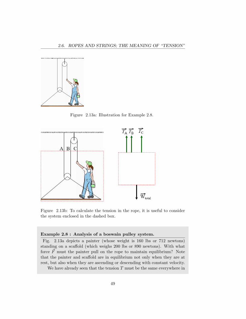
2.6. ROPES AND STRINGS; THE MEANING OF “TENSION”
Figure 2.13a: Illustration for Example 2.8.
Figure 2.13b: To calculate the tension in the rope, it is useful to considerthe system enclosed in the dashed box.
Example 2.8 : Analysis of a boswain pulley system.
Fig. 2.13a depicts a painter (whose weight is 160 lbs or 712 newtons)standing on a scaffold (which weighs 200 lbs or 890 newtons). With whatforce ~F must the painter pull on the rope to maintain equilibrium? Notethat the painter and scaffold are in equilibrium not only when they are atrest, but also when they are ascending or descending with constant velocity.
We have already seen that the tension T must be the same everywhere in
49
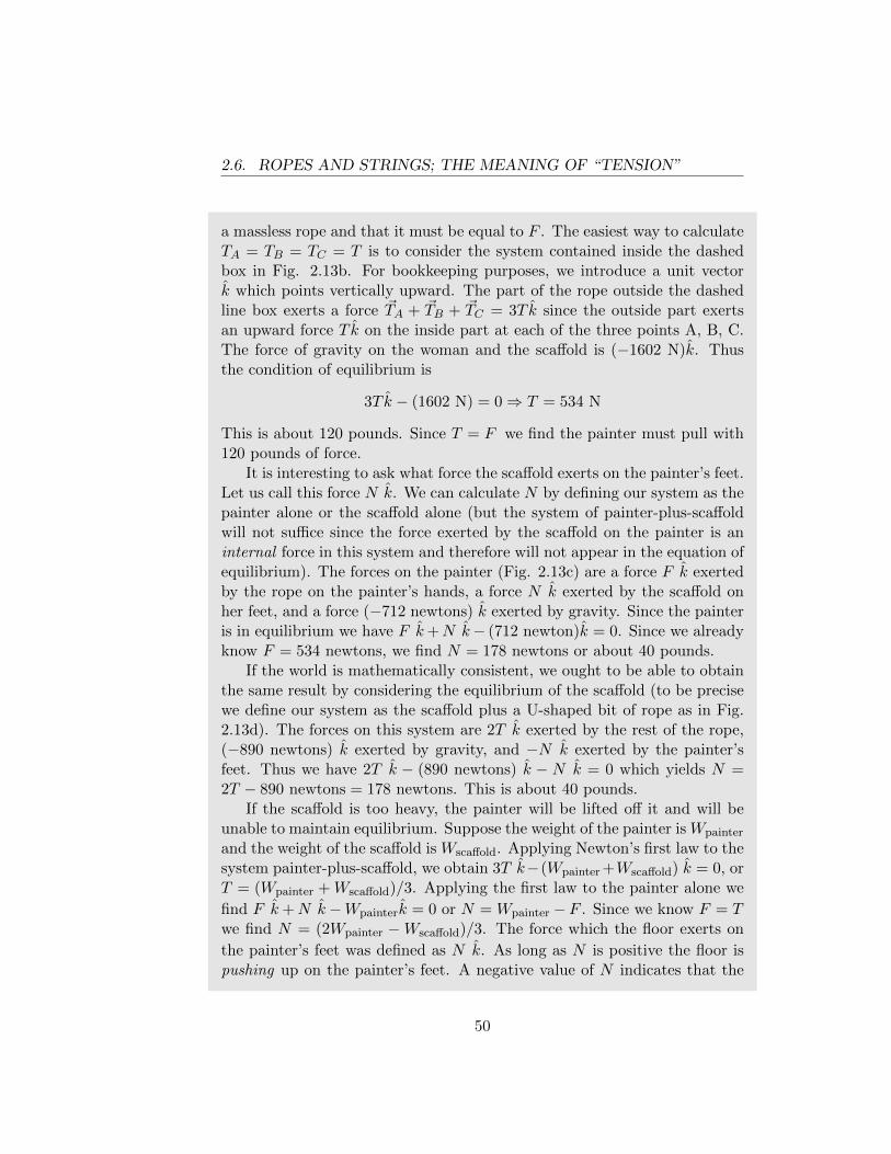
2.6. ROPES AND STRINGS; THE MEANING OF “TENSION”
a massless rope and that it must be equal to F . The easiest way to calculateTA = TB = TC = T is to consider the system contained inside the dashedbox in Fig. 2.13b. For bookkeeping purposes, we introduce a unit vectork which points vertically upward. The part of the rope outside the dashedline box exerts a force ~TA + ~TB + ~TC = 3T k since the outside part exertsan upward force T k on the inside part at each of the three points A, B, C.The force of gravity on the woman and the scaffold is (−1602 N)k. Thusthe condition of equilibrium is
3T k − (1602 N) = 0⇒ T = 534 N
This is about 120 pounds. Since T = F we find the painter must pull with120 pounds of force.
It is interesting to ask what force the scaffold exerts on the painter’s feet.Let us call this force N k. We can calculate N by defining our system as thepainter alone or the scaffold alone (but the system of painter-plus-scaffoldwill not suffice since the force exerted by the scaffold on the painter is aninternal force in this system and therefore will not appear in the equation ofequilibrium). The forces on the painter (Fig. 2.13c) are a force F k exertedby the rope on the painter’s hands, a force N k exerted by the scaffold onher feet, and a force (−712 newtons) k exerted by gravity. Since the painteris in equilibrium we have F k+N k− (712 newton)k = 0. Since we alreadyknow F = 534 newtons, we find N = 178 newtons or about 40 pounds.
If the world is mathematically consistent, we ought to be able to obtainthe same result by considering the equilibrium of the scaffold (to be precisewe define our system as the scaffold plus a U-shaped bit of rope as in Fig.2.13d). The forces on this system are 2T k exerted by the rest of the rope,(−890 newtons) k exerted by gravity, and −N k exerted by the painter’sfeet. Thus we have 2T k − (890 newtons) k − N k = 0 which yields N =2T − 890 newtons = 178 newtons. This is about 40 pounds.
If the scaffold is too heavy, the painter will be lifted off it and will beunable to maintain equilibrium. Suppose the weight of the painter is Wpainter
and the weight of the scaffold is Wscaffold. Applying Newton’s first law to thesystem painter-plus-scaffold, we obtain 3T k−(Wpainter +Wscaffold) k = 0, orT = (Wpainter +Wscaffold)/3. Applying the first law to the painter alone we
find F k+N k−Wpainterk = 0 or N = Wpainter − F . Since we know F = Twe find N = (2Wpainter −Wscaffold)/3. The force which the floor exerts on
the painter’s feet was defined as N k. As long as N is positive the floor ispushing up on the painter’s feet. A negative value of N indicates that the
50
2.6. ROPES AND STRINGS; THE MEANING OF “TENSION”
floor must be pulling down on the painter’s feet; this is not possible unlessher feet are strapped down to the floor. Clearly the critical value of Wscaffold
(beyond which equilibrium will not be possible unless the painter’s feet arestrapped down) is found by setting N = 0. This gives Wscaffold = 2Wpainter.If the painter weighs 160 pounds, she will “lift off” if the scaffold weighsmore than 320 pounds.
Figure 2.13c: The free-body diagram for the painter. This enables us tocalculate the force exerted by the scaffold on the painter’s feet.
51
2.7. FRICTION
Figure 2.13d: We can also calculate the force exerted by the painter’s feeton the scaffold by considering this free-body diagram.
2.7 Friction
When the surfaces of two bodies are in contact, it is frequently the casethat the force which one body exerts on the other has not only a componentperpendicular to the surfaces, but also a a component parallel to the surface.The latter force is called a frictional force and plays an essential role inmany familiar phenomena. For example, an automobile could neither bedriven up a hill nor parked on a hill if friction did not exist. Nor could thecar negotiate a curve. In the absence of friction, a passenger standing in asubway car would slide to the rear of the car when the train accelerates. Weare accustomed to think of friction as undesirable (and spend considerablemoney on lubrication to reduce the frictional force which exists when onesurface slides along another), but the preceding examples show that frictionis frequently desirable and essential.
It should hardly be necessary to emphasize that the validity of Newton’slaws does not require the unrealistic assumption of a world without friction.Newton’s laws describe the real world with real forces. Indeed, in someproblems we assume that there is no friction, but this is not conceptuallynecessary. Most of Newton’s predecessors did not realize that no force isrequired to keep a body moving with constant velocity; they observed thatthey had to push an object in order to keep it moving along a horizontaltable. This does not imply that Newton’s first law is false; the necessary
52
2.7. FRICTION
push is simply equal and opposite to the frictional force exerted by the table.Today, with air tracks and air tables which actually suspend a puck or cartabove a surface by means of a thin cushion of air, we can come very close toan experimental realization of a frictionless surface. No one who has playedwith an air track or air table believes that a force is necessary to keep abody moving.
The microscopic origin of frictional forces is not fully understood, nor issuch an understanding necessary for our purposes. In some situations onecan calculate the magnitude of the frictional forces without even knowninganything about the nature of the surfaces. In other situations it is necessaryto know more about the surfaces (i.e. their composition and smoothness).Consideration of a few simple examples will probably prove more enlighten-ing than an abstract discussion of this subject.
Figure 2.14d: Illustration for Example 2.9.
Example 2.9 : A block on a table with friction.
Consider a block at rest on a horizontal table (Fig. 2.14d). The onlyforces acting on the block are the gravitational force ~W (directed downward)and the normal force ~N (directed upward) which is exerted by the table.Newton’s first law requires ~N+ ~W = 0. Now suppose that a horizontal force~F is applied to the block. Our experience tells us that on a real table (i.e.a table which is not perfectly smooth) the block will remain at rest if themagnitude of ~F is not too large.
Newton’s first law requires that another horizontal force, equal in mag-
53
2.7. FRICTION
nitude and opposite in direction to ~F , must be acting on the block. Thisforce, which is exerted by the surface of the table on the bottom surfaceof the block, is called the frictional force and is denoted by the symbol ~f .Newton’s first law states8 ~F + ~f = 0. For purposes of simple visualization,one can think of both the table and the block as being covered with minuteroughnesses (ridges and valleys), so that their surfaces intermesh to someextent, like a set of gear teeth (Fig. 2.15d). The frictional force is sim-ply the horizontal force exerted by the table’s roughnesses on the block’sroughnesses.
Figure 2.15d: Schematic representation of the origin of static friction. Ac-tually, the roughnesses of surfaces are much smaller than represented herebut they exist even for surfaces that are smooth to the touch.
As long as the block in Example 2.9 is at rest, the magnitude f of thefrictional force is simply equal to the magnitude F of the applied force. Inthis case we have calculated f without knowing anything about the natureof the surfaces.
An obvious question is: how large a force F must be applied in order tocause the block to slip? The answer depends, of course, on the materials ofwhich the block and the table are made and also on the smoothness of thesurfaces. Even if we know the composition and smoothness of both surfaces,it is virtually impossible to answer this question from first principles since adetailed understanding of various interactions on a microscopic (molecular)scale is required. Fortunately, the question can be answered experimentallyand a large amount of data can be summarized by a very simple “law”. Westress that this law is not fundamental (in contrast with Newton’s
8The full statement of the first law in this case is ~N + ~W + ~F + ~f = 0. But since ~Nand ~W are vertical and ~F and ~f are horizontal, it follows that ~N + ~W = 0 and ~F + ~f = 0.
54
2.7. FRICTION
laws) but merely provides a useful summary of experimental data.
In general, when the surfaces of two bodies are in contact, body A exertsa normal force ~N (perpendicular to the surface) and a frictional force ~f(parallel to the surface) on body B, and Newton’s third law requires that Bexert forces − ~N and −~f on A. We denote the magnitude of ~N (and − ~N)by N and the magnitude of ~f (and −~f) by f . In Example 2.9, N is equal tothe weight W of the block and f is equal to the magnitude F of the appliedforce. N can be varied by placing additional weights on top of the block.For each value of N we can measure Fmax, the largest value of F whichcan be applied without causing the block to slip. It is found that theratio Fmax/N remains constant as N is varied. This ratio is called thecoefficient of static friction between the two surfaces and is denoted bythe symbol µs.
The coefficient of static friction depends on the composition and smooth-ness of the surfaces, but does not depend on the area of contact. Thus, if theblock were replaced by another block of the same material and smoothnessbut twice the bottom surface area, the ratio Fmax/N would be found to bethe same as for the original block.9 Since F = f as long as the block is notslipping, it follows that Fmax = fmax, where fmax is the largest value of thefrictional force which one surface can exert on the other (for a given valueof the normal force).
Thus we arrive at a statement of the experimental “law of staticfriction”: when two surfaces are in contact with no motion of one surfacerelative to the other (i.e. no slipping), the maximum value of the frictionalforce which one surface can exert on the other is proportional to the normalforce, the coefficient of proportionality µs depending only on the compositionand smoothness of the two surfaces, i.e
f
N≤ µs (2.6)
We stress that eqn.( 2.6) is an inequality. Equality holds only when slippingis about to occur. Many students fall into the habit of automatically replac-ing f by µsN with disastrous consequences. For example, if no horizontalforce ~F is applied to the block in Example 2.9, then there is no frictionalforce and the ratio f/N is zero even though µs is not zero.
9The fact that Fmax/N does not vary when the area of contact A is varied can bededuced from the fact that Fmax/N is independent of N for fixed A. The proof is left asa challenge to the interested reader.
55
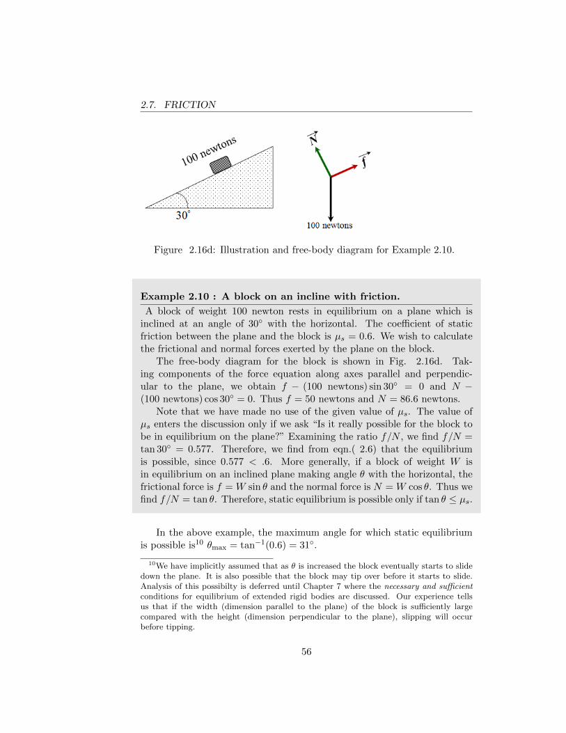
2.7. FRICTION
Figure 2.16d: Illustration and free-body diagram for Example 2.10.
Example 2.10 : A block on an incline with friction.
A block of weight 100 newton rests in equilibrium on a plane which isinclined at an angle of 30◦ with the horizontal. The coefficient of staticfriction between the plane and the block is µs = 0.6. We wish to calculatethe frictional and normal forces exerted by the plane on the block.
The free-body diagram for the block is shown in Fig. 2.16d. Tak-ing components of the force equation along axes parallel and perpendic-ular to the plane, we obtain f − (100 newtons) sin 30◦ = 0 and N −(100 newtons) cos 30◦ = 0. Thus f = 50 newtons and N = 86.6 newtons.
Note that we have made no use of the given value of µs. The value ofµs enters the discussion only if we ask “Is it really possible for the block tobe in equilibrium on the plane?” Examining the ratio f/N , we find f/N =tan 30◦ = 0.577. Therefore, we find from eqn.( 2.6) that the equilibriumis possible, since 0.577 < .6. More generally, if a block of weight W isin equilibrium on an inclined plane making angle θ with the horizontal, thefrictional force is f = W sin θ and the normal force is N = W cos θ. Thus wefind f/N = tan θ. Therefore, static equilibrium is possible only if tan θ ≤ µs.
In the above example, the maximum angle for which static equilibriumis possible is10 θmax = tan−1(0.6) = 31◦.
10We have implicitly assumed that as θ is increased the block eventually starts to slidedown the plane. It is also possible that the block may tip over before it starts to slide.Analysis of this possibilty is deferred until Chapter 7 where the necessary and sufficientconditions for equilibrium of extended rigid bodies are discussed. Our experience tellsus that if the width (dimension parallel to the plane) of the block is sufficiently largecompared with the height (dimension perpendicular to the plane), slipping will occurbefore tipping.
56
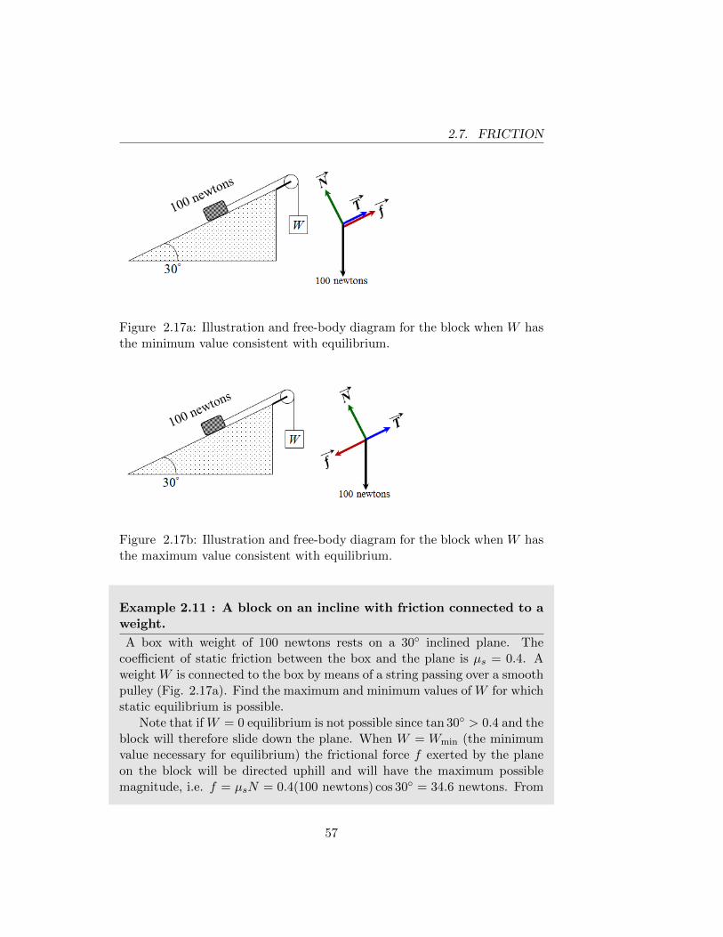
2.7. FRICTION
Figure 2.17a: Illustration and free-body diagram for the block when W hasthe minimum value consistent with equilibrium.
Figure 2.17b: Illustration and free-body diagram for the block when W hasthe maximum value consistent with equilibrium.
Example 2.11 : A block on an incline with friction connected to aweight.
A box with weight of 100 newtons rests on a 30◦ inclined plane. Thecoefficient of static friction between the box and the plane is µs = 0.4. Aweight W is connected to the box by means of a string passing over a smoothpulley (Fig. 2.17a). Find the maximum and minimum values of W for whichstatic equilibrium is possible.
Note that if W = 0 equilibrium is not possible since tan 30◦ > 0.4 and theblock will therefore slide down the plane. When W = Wmin (the minimumvalue necessary for equilibrium) the frictional force f exerted by the planeon the block will be directed uphill and will have the maximum possiblemagnitude, i.e. f = µsN = 0.4(100 newtons) cos 30◦ = 34.6 newtons. From
57
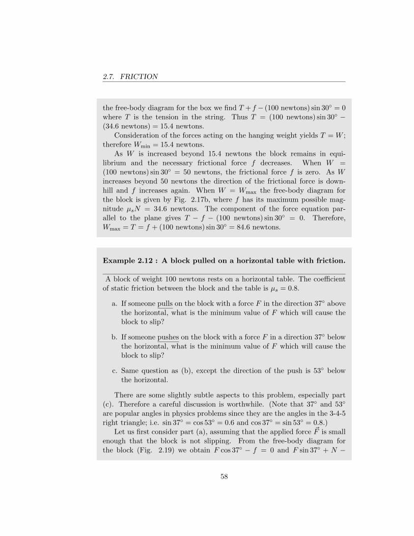
2.7. FRICTION
the free-body diagram for the box we find T + f − (100 newtons) sin 30◦ = 0where T is the tension in the string. Thus T = (100 newtons) sin 30◦ −(34.6 newtons) = 15.4 newtons.
Consideration of the forces acting on the hanging weight yields T = W ;therefore Wmin = 15.4 newtons.
As W is increased beyond 15.4 newtons the block remains in equi-librium and the necessary frictional force f decreases. When W =(100 newtons) sin 30◦ = 50 newtons, the frictional force f is zero. As Wincreases beyond 50 newtons the direction of the frictional force is down-hill and f increases again. When W = Wmax the free-body diagram forthe block is given by Fig. 2.17b, where f has its maximum possible mag-nitude µsN = 34.6 newtons. The component of the force equation par-allel to the plane gives T − f − (100 newtons) sin 30◦ = 0. Therefore,Wmax = T = f + (100 newtons) sin 30◦ = 84.6 newtons.
Example 2.12 : A block pulled on a horizontal table with friction.
A block of weight 100 newtons rests on a horizontal table. The coefficientof static friction between the block and the table is µs = 0.8.
a. If someone pulls on the block with a force F in the direction 37◦ abovethe horizontal, what is the minimum value of F which will cause theblock to slip?
b. If someone pushes on the block with a force F in a direction 37◦ belowthe horizontal, what is the minimum value of F which will cause theblock to slip?
c. Same question as (b), except the direction of the push is 53◦ belowthe horizontal.
There are some slightly subtle aspects to this problem, especially part(c). Therefore a careful discussion is worthwhile. (Note that 37◦ and 53◦
are popular angles in physics problems since they are the angles in the 3-4-5right triangle; i.e. sin 37◦ = cos 53◦ = 0.6 and cos 37◦ = sin 53◦ = 0.8.)
Let us first consider part (a), assuming that the applied force ~F is smallenough that the block is not slipping. From the free-body diagram forthe block (Fig. 2.19) we obtain F cos 37◦ − f = 0 and F sin 37◦ + N −
58
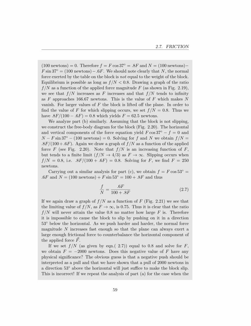
2.7. FRICTION
(100 newtons) = 0. Therefore f = F cos 37◦ = .8F andN = (100 newtons)−F sin 37◦ = (100 newtons)− .6F . We should note clearly that N , the normalforce exerted by the table on the block is not equal to the weight of the block.Equilibrium is possible as long as f/N < 0.8. Drawing a graph of the ratiof/N as a function of the applied force magnitude F (as shown in Fig. 2.19),we see that f/N increases as F increases and that f/N tends to infinityas F approaches 166.67 newtons. This is the value of F which makes Nvanish. For larger values of F the block is lifted off the plane. In order tofind the value of F for which slipping occurs, we set f/N = 0.8. Thus wehave .8F/(100− .6F ) = 0.8 which yields F = 62.5 newtons.
We analyze part (b) similarly. Assuming that the block is not slipping,we construct the free-body diagram for the block (Fig. 2.20). The horizontaland vertical components of the force equation yield F cos 37◦ − f = 0 andN − F sin 37◦ − (100 newtons) = 0. Solving for f and N we obtain f/N =.8F/(100+ .6F ). Again we draw a graph of f/N as a function of the appliedforce F (see Fig. 2.20). Note that f/N is an increasing function of F ,but tends to a finite limit (f/N → 4/3) as F → ∞. Slipping occurs whenf/N = 0.8, i.e. .8F/(100 + .6F ) = 0.8. Solving for F , we find F = 250newtons.
Carrying out a similar analysis for part (c), we obtain f = F cos 53◦ =.6F and N = (100 newtons) + F sin 53◦ = 100 + .8F and thus
f
N=
.6F
100 + .8F(2.7)
If we again draw a graph of f/N as a function of F (Fig. 2.21) we see thatthe limiting value of f/N , as F →∞, is 0.75. Thus it is clear that the ratiof/N will never attain the value 0.8 no matter how large F is. Thereforeit is impossible to cause the block to slip by pushing on it in a direction53◦ below the horizontal. As we push harder and harder, the normal forcemagnitude N increases fast enough so that the plane can always exert alarge enough frictional force to counterbalance the horizontal component ofthe applied force ~F .
If we set f/N (as given by eqn.( 2.7)) equal to 0.8 and solve for F ,we obtain F = −2000 newtons. Does this negative value of F have anyphysical significance? The obvious guess is that a negative push should beinterpreted as a pull and that we have shown that a pull of 2000 newtons ina direction 53◦ above the horizontal will just suffice to make the block slip.This is incorrect! If we repeat the analysis of part (a) for the case when the
59
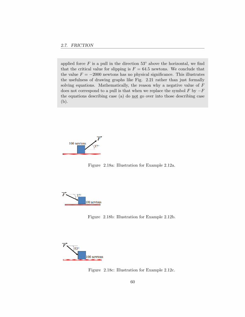
2.7. FRICTION
applied force F is a pull in the direction 53◦ above the horizontal, we findthat the critical value for slipping is F = 64.5 newtons. We conclude thatthe value F = −2000 newtons has no physical significance. This illustratesthe usefulness of drawing graphs like Fig. 2.21 rather than just formallysolving equations. Mathematically, the reason why a negative value of Fdoes not correspond to a pull is that when we replace the symbol F by −Fthe equations describing case (a) do not go over into those describing case(b).
Figure 2.18a: Illustration for Example 2.12a.
Figure 2.18b: Illustration for Example 2.12b.
Figure 2.18c: Illustration for Example 2.12c.
60
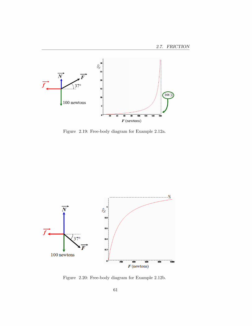
2.7. FRICTION
Figure 2.19: Free-body diagram for Example 2.12a.
Figure 2.20: Free-body diagram for Example 2.12b.
61
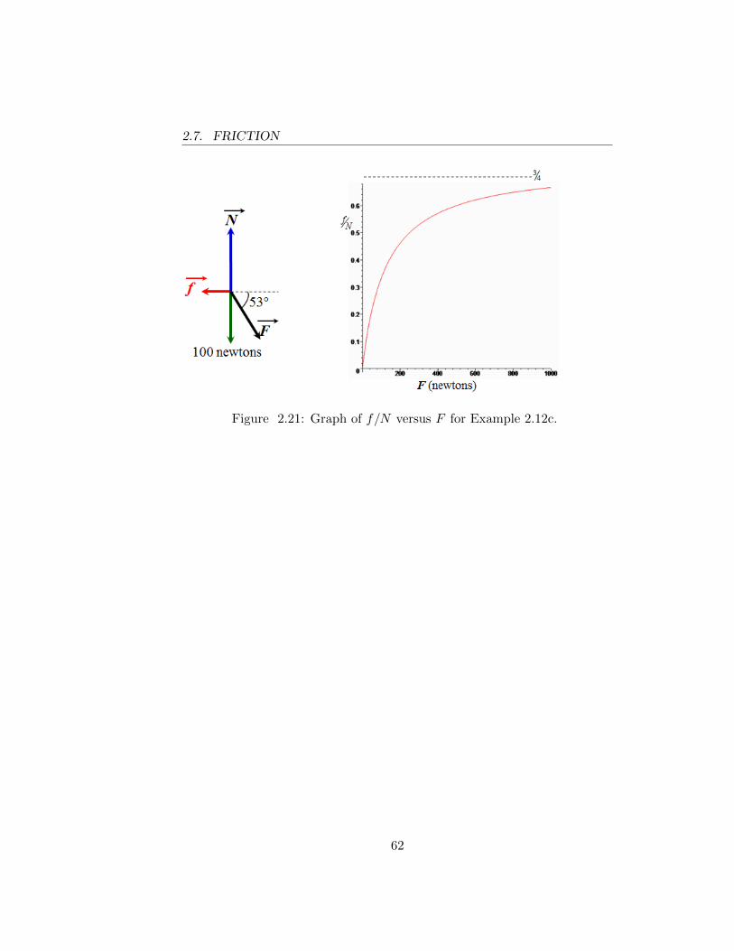
2.7. FRICTION
Figure 2.21: Graph of f/N versus F for Example 2.12c.
62
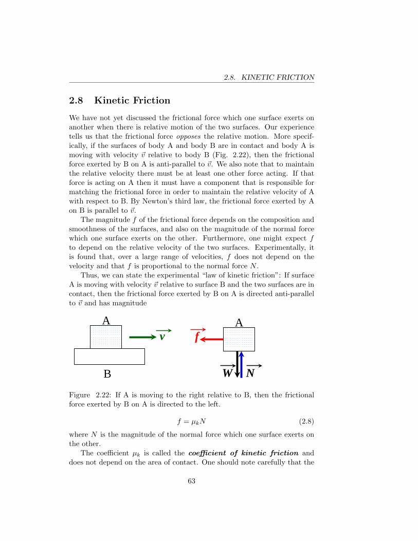
2.8. KINETIC FRICTION
2.8 Kinetic Friction
We have not yet discussed the frictional force which one surface exerts onanother when there is relative motion of the two surfaces. Our experiencetells us that the frictional force opposes the relative motion. More specif-ically, if the surfaces of body A and body B are in contact and body A ismoving with velocity ~v relative to body B (Fig. 2.22), then the frictionalforce exerted by B on A is anti-parallel to ~v. We also note that to maintainthe relative velocity there must be at least one other force acting. If thatforce is acting on A then it must have a component that is responsible formatching the frictional force in order to maintain the relative velocity of Awith respect to B. By Newton’s third law, the frictional force exerted by Aon B is parallel to ~v.
The magnitude f of the frictional force depends on the composition andsmoothness of the surfaces, and also on the magnitude of the normal forcewhich one surface exerts on the other. Furthermore, one might expect fto depend on the relative velocity of the two surfaces. Experimentally, itis found that, over a large range of velocities, f does not depend on thevelocity and that f is proportional to the normal force N .
Thus, we can state the experimental “law of kinetic friction”: If surfaceA is moving with velocity ~v relative to surface B and the two surfaces are incontact, then the frictional force exerted by B on A is directed anti-parallelto ~v and has magnitude
v A
B
A f
N W
Figure 2.22: If A is moving to the right relative to B, then the frictionalforce exerted by B on A is directed to the left.
f = µkN (2.8)
where N is the magnitude of the normal force which one surface exerts onthe other.
The coefficient µk is called the coefficient of kinetic friction anddoes not depend on the area of contact. One should note carefully that the
63
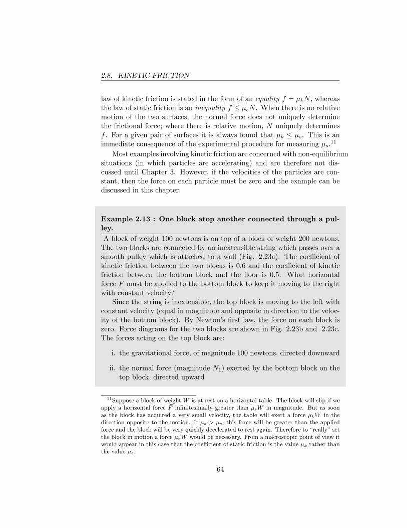
2.8. KINETIC FRICTION
law of kinetic friction is stated in the form of an equality f = µkN , whereasthe law of static friction is an inequality f ≤ µsN . When there is no relativemotion of the two surfaces, the normal force does not uniquely determinethe frictional force; where there is relative motion, N uniquely determinesf . For a given pair of surfaces it is always found that µk ≤ µs. This is animmediate consequence of the experimental procedure for measuring µs.
11
Most examples involving kinetic friction are concerned with non-equilibriumsituations (in which particles are accelerating) and are therefore not dis-cussed until Chapter 3. However, if the velocities of the particles are con-stant, then the force on each particle must be zero and the example can bediscussed in this chapter.
Example 2.13 : One block atop another connected through a pul-ley.
A block of weight 100 newtons is on top of a block of weight 200 newtons.The two blocks are connected by an inextensible string which passes over asmooth pulley which is attached to a wall (Fig. 2.23a). The coefficient ofkinetic friction between the two blocks is 0.6 and the coefficient of kineticfriction between the bottom block and the floor is 0.5. What horizontalforce F must be applied to the bottom block to keep it moving to the rightwith constant velocity?
Since the string is inextensible, the top block is moving to the left withconstant velocity (equal in magnitude and opposite in direction to the veloc-ity of the bottom block). By Newton’s first law, the force on each block iszero. Force diagrams for the two blocks are shown in Fig. 2.23b and 2.23c.The forces acting on the top block are:
i. the gravitational force, of magnitude 100 newtons, directed downward
ii. the normal force (magnitude N1) exerted by the bottom block on thetop block, directed upward
11Suppose a block of weight W is at rest on a horizontal table. The block will slip if weapply a horizontal force ~F infinitesimally greater than µsW in magnitude. But as soonas the block has acquired a very small velocity, the table will exert a force µkW in thedirection opposite to the motion. If µk > µs, this force will be greater than the appliedforce and the block will be very quickly decelerated to rest again. Therefore to “really” setthe block in motion a force µkW would be necessary. From a macroscopic point of view itwould appear in this case that the coefficient of static friction is the value µk rather thanthe value µs.
64
2.8. KINETIC FRICTION
iii. the force exerted by the string (magnitude T ), directed to the left
iv. the frictional force (magnitude f1) exerted by the bottom block on thetop block, directed to the right.
The vertical and horizontal components of Newton’s first law give N1 = 100newtons and T = f1. Furthermore, the law of kinetic friction gives f1 =0.6(100 newtons) = 60 newtons. Therefore T = 60 newtons.
The forces acting on the bottom block are:
i. the gravitational force, of magnitude 200 newtons, directed downward
ii. the normal force (magnitude N2) exerted by the floor on the bottomblock, directed upward
iii. the force exerted by the string (magnitude T ), directed to the left
iv. the frictional force (magnitude f1) exerted by the top block on thebottom block, directed to the left
v. the frictional force (magnitude f2) exerted by the floor on the bottomblock, directed to the left
vi. the force F , directed to the right.
Newton’s first law gives N2−N1−(200 newtons) = 0 and F−T−f1−f2 = 0.Since N1 = 100 newtons, we find N2 = 300 newtons. Since f2 = 0.5 N2, wefind f2 = 150 newtons. Since T = 60 newtons and f1 = 60 newtons, we findF = 60+60+150 = 270 newtons. (If F were applied to the top block ratherthan the bottom one, what value of F would be required? This answer isalso 270! We can see this easily later when discussing energy considerations.)
65
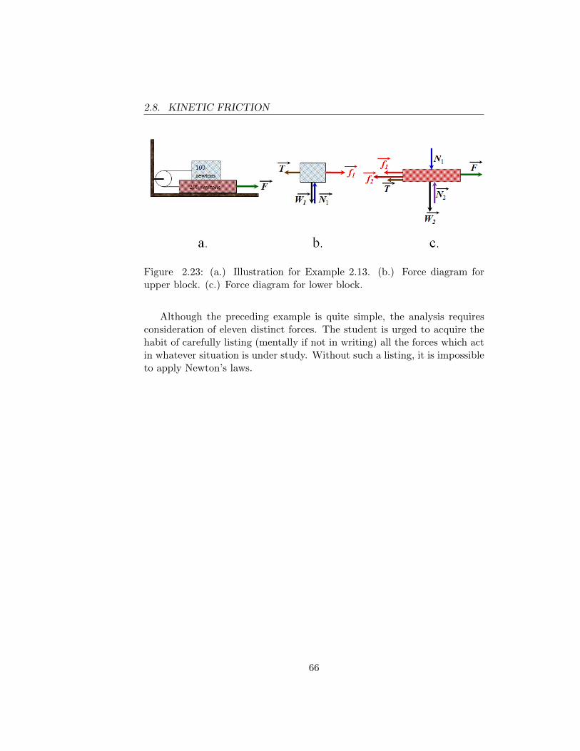
2.8. KINETIC FRICTION
Figure 2.23: (a.) Illustration for Example 2.13. (b.) Force diagram forupper block. (c.) Force diagram for lower block.
Although the preceding example is quite simple, the analysis requiresconsideration of eleven distinct forces. The student is urged to acquire thehabit of carefully listing (mentally if not in writing) all the forces which actin whatever situation is under study. Without such a listing, it is impossibleto apply Newton’s laws.
66
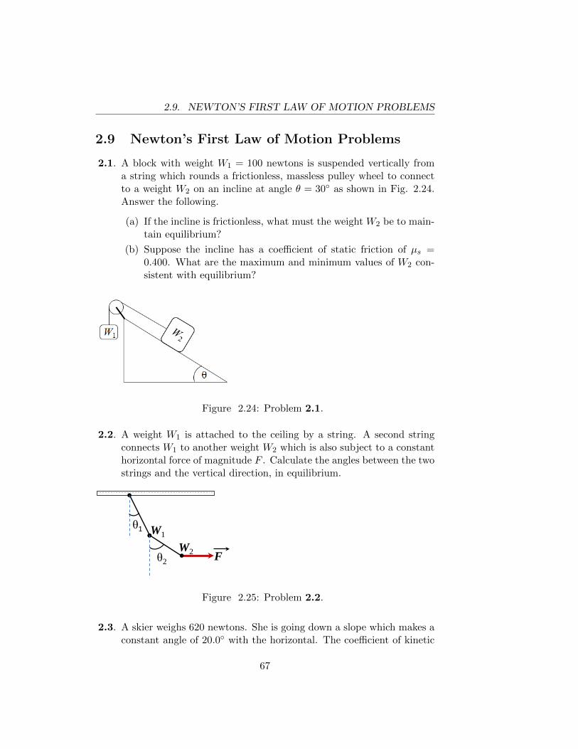
2.9. NEWTON’S FIRST LAW OF MOTION PROBLEMS
2.9 Newton’s First Law of Motion Problems
2.1. A block with weight W1 = 100 newtons is suspended vertically froma string which rounds a frictionless, massless pulley wheel to connectto a weight W2 on an incline at angle θ = 30◦ as shown in Fig. 2.24.Answer the following.
(a) If the incline is frictionless, what must the weight W2 be to main-tain equilibrium?
(b) Suppose the incline has a coefficient of static friction of µs =0.400. What are the maximum and minimum values of W2 con-sistent with equilibrium?
Figure 2.24: Problem 2.1.
2.2. A weight W1 is attached to the ceiling by a string. A second stringconnects W1 to another weight W2 which is also subject to a constanthorizontal force of magnitude F . Calculate the angles between the twostrings and the vertical direction, in equilibrium.
W1
W2 F
W1 W2 F
θ1
θ2
Figure 2.25: Problem 2.2.
2.3. A skier weighs 620 newtons. She is going down a slope which makes aconstant angle of 20.0◦ with the horizontal. The coefficient of kinetic
67
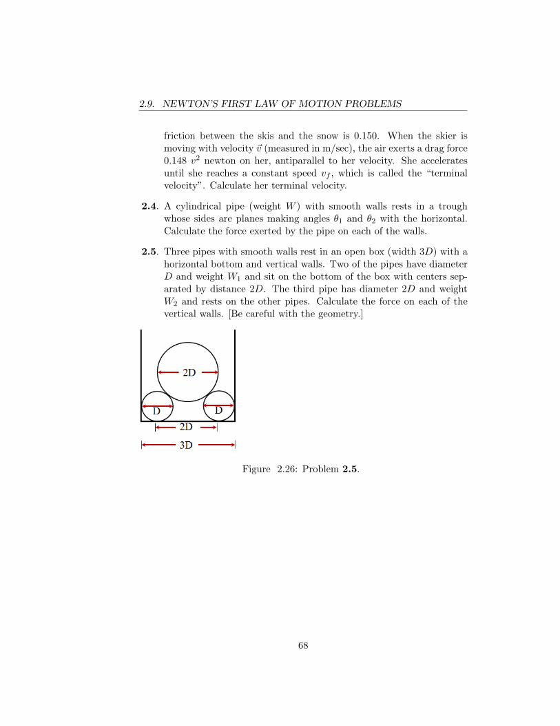
2.9. NEWTON’S FIRST LAW OF MOTION PROBLEMS
friction between the skis and the snow is 0.150. When the skier ismoving with velocity ~v (measured in m/sec), the air exerts a drag force0.148 v2 newton on her, antiparallel to her velocity. She acceleratesuntil she reaches a constant speed vf , which is called the “terminalvelocity”. Calculate her terminal velocity.
2.4. A cylindrical pipe (weight W ) with smooth walls rests in a troughwhose sides are planes making angles θ1 and θ2 with the horizontal.Calculate the force exerted by the pipe on each of the walls.
2.5. Three pipes with smooth walls rest in an open box (width 3D) with ahorizontal bottom and vertical walls. Two of the pipes have diameterD and weight W1 and sit on the bottom of the box with centers sep-arated by distance 2D. The third pipe has diameter 2D and weightW2 and rests on the other pipes. Calculate the force on each of thevertical walls. [Be careful with the geometry.]
Figure 2.26: Problem 2.5.
68
Chapter 3
NEWTON’S SECONDLAW; DYNAMICS OFPARTICLES
3.1 Dynamics Of Particles
Until now we have been discussing bodies in equilibrium, i.e. bodies subjectto no net force. According to Newton’s first law the velocity remains con-stant when no net force acts on the body. Newton’s second law tells us in aquantitative way how a body modifies its motion when a force acts on thebody.
In Newton’s own words: “The change of motion is proportional to themotive force impressed, and is made in the direction of the right line inwhich that force is impressed.”[New] Not all the words in this statementare familiar to today’s physicist. Newton defines “motion” as the productof “the quantity of matter” and the velocity; Newton’s “motion” is called“momentum” today. By “change of motion” he means “rate of change ofmotion”.
In the concise language of vectors
~F = m~a (3.1)
Two of the three symbols in eqn.( 3.1) have already been defined; ~a isa purely kinematic quantity which was defined in Chapter 1, and ~F wasdefined in Chapter 2. The third symbol (m) requires some discussion. The
69

3.1. DYNAMICS OF PARTICLES
definition of “mass” as the “quantity of matter” is somewhat vague.Eqn.( 3.1) permits us to devise a precise operational procedure for measuringthe mass of a body. The equation states that if we subject a particular bodyto various forces, the acceleration of the body is proportional to the forceacting on the body, i.e. ~a = k ~F . The proportionality constant k is aproperty of the body; the larger the value of k, the easier it is to acceleratethe body. The mass of the body is defined as the reciprocal of k, i.e.m = 1/k.
In the English system of units the fundamental quantities are length(foot), time (seconds), and force (pounds). The pound was defined as theforce exerted by the earth on a certain standard body located at a certainplace. We can use eqn.( 3.1) to determine the mass m of a body. The massis the force on the body (measured in pounds) divided by the acceleration(measured in ft/sec2). The English unit of mass, called the slug , is a derivedunit having the dimensions of lb-sec2/ft. A body whose mass is one slug willexperience an acceleration of 1 ft/sec2 when subjected to a force of 1 lb. Abody whose mass is two slugs will experience an acceleration of 0.5 ft/sec2
when subjected to a force of 1 lb, etc.Let us apply eqn.( 3.1) to a body of weight W freely falling at the
“standard location”. It is found experimentally that all freely falling bodieshave the same acceleration at a given place; at the standard location thenumerical value of this acceleration (which is called g) is 32.174 ft/sec2.Eqn.( 3.1) says W = mg. Thus the mass m of a body is related to its weightW by the equation
m =W
g(3.2)
Note that W and g depend on the place where the body is located, butNewton’s second law asserts that m is a property of the body, independentof the location of the body. A body whose mass is 1 slug weighs 32.174 lbat the standard location but can have a slightly different weight at anotherlocation.
In the metric system the fundamental units are length (meters), time(seconds), and mass (kilograms). The kilogram can be defined as the massof 1000 cm3 of water under standard conditions of temperature and pres-sure, but (for greater accuracy) may eventually be defined in terms of otherfundamental constants. The metric unit of force, the newton , is the forcewhich must be applied to a body of mass 1 kilogram in order to give thatbody an acceleration of 1 meter/sec2. One newton is equal to approximately0.225 pounds and one pound is equal to approximately 4.45 newtons.
Once we have a body of unit mass, we can measure the mass of any
70
3.1. DYNAMICS OF PARTICLES
other body by subjecting it and the standard body to the same force andmeasuring the ratio of the accelerations of the two bodies. If the same forceis applied to body #1 and body #2, we have M1a1 = M2a2. Thus if M1 = 1,we have M2 = a1/a2. Note that this procedure for measuring the mass doesnot require weighing the object, nor does it require counting the number ofprotons, neutrons, and electrons in the object.1
If ~F = 0, then eqn.( 3.1) says that ~a = 0 and therefore the velocity~v is constant. Thus it is clear that the second law includes the first lawas a special case. It should also be understood that if we include in ourlist of forces only the forces which have been discussed in Chapter 2, thenNewton’s second law is true only in an inertial frame. If, for example, weuse axes attached to a rotating merry-go-round or to an accelerating freightcar, then Newton’s second law will not be true; a body will accelerate withrespect to such axes even when no forces are acting on it.
We shall now use the second law to analyze a series of examples.
Example 3.1 : A block on a smooth incline.
A block of mass m is sliding down a smooth plane which is inclined at angleθ to the horizontal. Calculate the acceleration of the block and the forcewhich the plane exerts on the block.
Two forces are acting on the block: the gravitational force of magnitudemg, directed vertically downward, and the normal force N exerted by theplane. If we introduce x− and y−axes, then the vector equation ~F = m~a
1It seems intuitively obvious that if an object is composed of constituent particles(protons, neutrons, and electrons) the mass of the object is equal to the sum of the massesof the constituents. However, if neutrons and protons are assembled to form a heavynucleus, the mass of the nucleus is found to be about 1% less than the sum of the massesof the constituent particles. Einstein predicted (correctly) that this “mass defect” wouldbe equal to the work necessary to disassemble the nucleus divided by the square of thevelocity of light. Thus, Newton’s idea of mass as the “quantity of matter” is untenablewhen the particles are held together by the very strong nuclear force. Similarly, theweight of the nucleus is significantly less than the sum of the weights of the constituentparticles. Nevertheless, all objects (protons, neutrons, nuclei, baseballs) fall with thesame acceleration g at a given location. This fact has been verified to fantastically highaccuracy[HB01]. Thus, the proportionality of weight and mass, expressed by the equationW = mg, appears to be a much more sacred law of nature than the additivity of weightor mass. In everyday life, where nuclear forces are not involved, the “mass defect” is verysmall and, for all practical purposes, the additivity property holds.
71
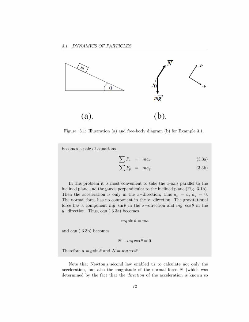
3.1. DYNAMICS OF PARTICLES
Figure 3.1: Illustration (a) and free-body diagram (b) for Example 3.1.
becomes a pair of equations ∑Fx = max (3.3a)∑Fy = may (3.3b)
In this problem it is most convenient to take the x-axis parallel to theinclined plane and the y-axis perpendicular to the inclined plane (Fig. 3.1b).Then the acceleration is only in the x−direction; thus ax = a, ay = 0.The normal force has no component in the x−direction. The gravitationalforce has a component mg sin θ in the x−direction and mg cos θ in they−direction. Thus, eqn.( 3.3a) becomes
mg sin θ = ma
and eqn.( 3.3b) becomes
N −mg cos θ = 0.
Therefore a = g sin θ and N = mg cos θ.
Note that Newton’s second law enabled us to calculate not only theacceleration, but also the magnitude of the normal force N (which wasdetermined by the fact that the direction of the acceleration is known so
72
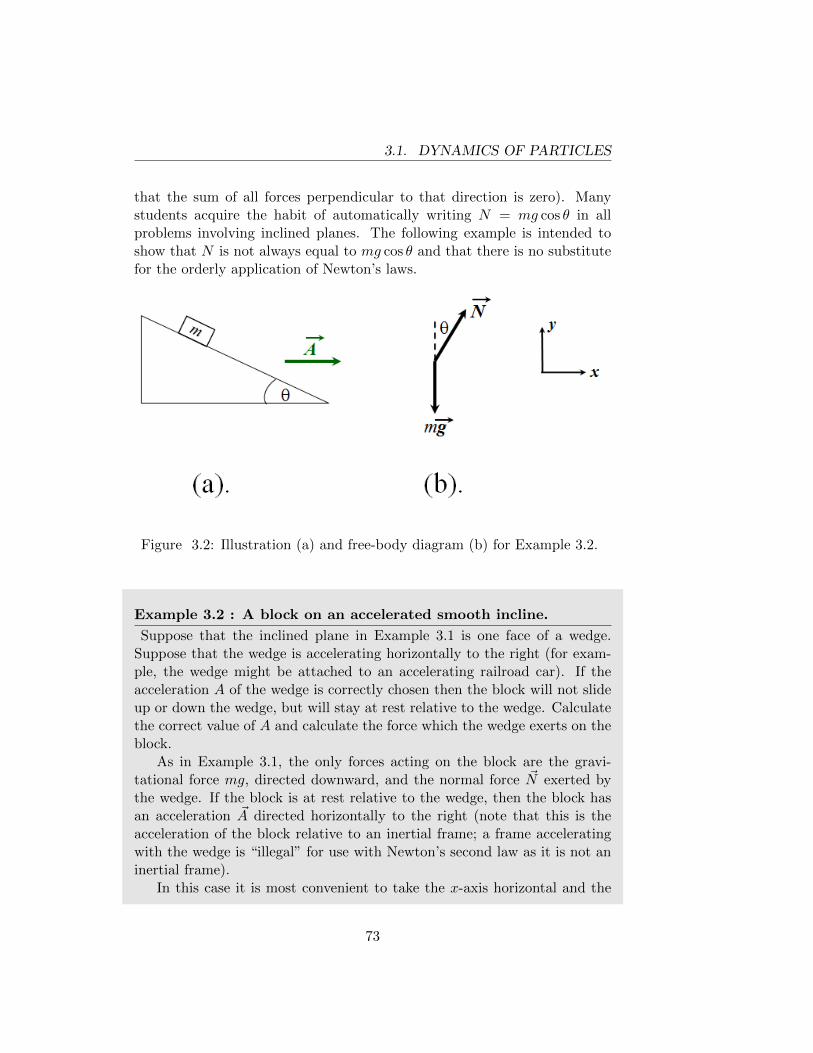
3.1. DYNAMICS OF PARTICLES
that the sum of all forces perpendicular to that direction is zero). Manystudents acquire the habit of automatically writing N = mg cos θ in allproblems involving inclined planes. The following example is intended toshow that N is not always equal to mg cos θ and that there is no substitutefor the orderly application of Newton’s laws.
Figure 3.2: Illustration (a) and free-body diagram (b) for Example 3.2.
Example 3.2 : A block on an accelerated smooth incline.
Suppose that the inclined plane in Example 3.1 is one face of a wedge.Suppose that the wedge is accelerating horizontally to the right (for exam-ple, the wedge might be attached to an accelerating railroad car). If theacceleration A of the wedge is correctly chosen then the block will not slideup or down the wedge, but will stay at rest relative to the wedge. Calculatethe correct value of A and calculate the force which the wedge exerts on theblock.
As in Example 3.1, the only forces acting on the block are the gravi-tational force mg, directed downward, and the normal force ~N exerted bythe wedge. If the block is at rest relative to the wedge, then the block hasan acceleration ~A directed horizontally to the right (note that this is theacceleration of the block relative to an inertial frame; a frame acceleratingwith the wedge is “illegal” for use with Newton’s second law as it is not aninertial frame).
In this case it is most convenient to take the x-axis horizontal and the
73
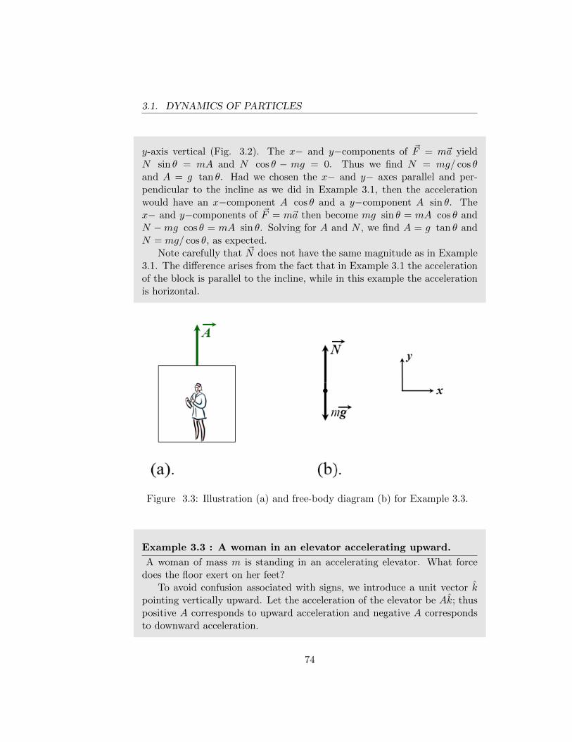
3.1. DYNAMICS OF PARTICLES
y-axis vertical (Fig. 3.2). The x− and y−components of ~F = m~a yieldN sin θ = mA and N cos θ − mg = 0. Thus we find N = mg/ cos θand A = g tan θ. Had we chosen the x− and y− axes parallel and per-pendicular to the incline as we did in Example 3.1, then the accelerationwould have an x−component A cos θ and a y−component A sin θ. Thex− and y−components of ~F = m~a then become mg sin θ = mA cos θ andN −mg cos θ = mA sin θ. Solving for A and N , we find A = g tan θ andN = mg/ cos θ, as expected.
Note carefully that ~N does not have the same magnitude as in Example3.1. The difference arises from the fact that in Example 3.1 the accelerationof the block is parallel to the incline, while in this example the accelerationis horizontal.
Figure 3.3: Illustration (a) and free-body diagram (b) for Example 3.3.
Example 3.3 : A woman in an elevator accelerating upward.
A woman of mass m is standing in an accelerating elevator. What forcedoes the floor exert on her feet?
To avoid confusion associated with signs, we introduce a unit vector kpointing vertically upward. Let the acceleration of the elevator be Ak; thuspositive A corresponds to upward acceleration and negative A correspondsto downward acceleration.
74
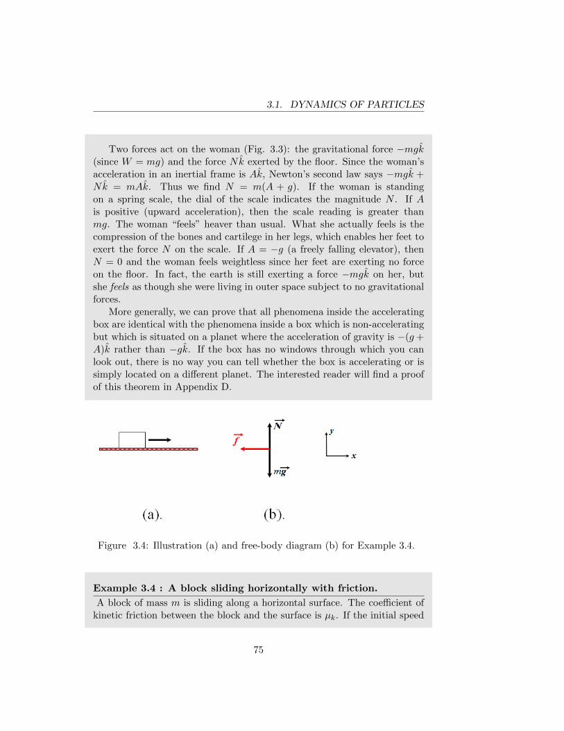
3.1. DYNAMICS OF PARTICLES
Two forces act on the woman (Fig. 3.3): the gravitational force −mgk(since W = mg) and the force Nk exerted by the floor. Since the woman’sacceleration in an inertial frame is Ak, Newton’s second law says −mgk +Nk = mAk. Thus we find N = m(A + g). If the woman is standingon a spring scale, the dial of the scale indicates the magnitude N . If Ais positive (upward acceleration), then the scale reading is greater thanmg. The woman “feels” heaver than usual. What she actually feels is thecompression of the bones and cartilege in her legs, which enables her feet toexert the force N on the scale. If A = −g (a freely falling elevator), thenN = 0 and the woman feels weightless since her feet are exerting no forceon the floor. In fact, the earth is still exerting a force −mgk on her, butshe feels as though she were living in outer space subject to no gravitationalforces.
More generally, we can prove that all phenomena inside the acceleratingbox are identical with the phenomena inside a box which is non-acceleratingbut which is situated on a planet where the acceleration of gravity is −(g+A)k rather than −gk. If the box has no windows through which you canlook out, there is no way you can tell whether the box is accelerating or issimply located on a different planet. The interested reader will find a proofof this theorem in Appendix D.
Figure 3.4: Illustration (a) and free-body diagram (b) for Example 3.4.
Example 3.4 : A block sliding horizontally with friction.
A block of mass m is sliding along a horizontal surface. The coefficient ofkinetic friction between the block and the surface is µk. If the initial speed
75
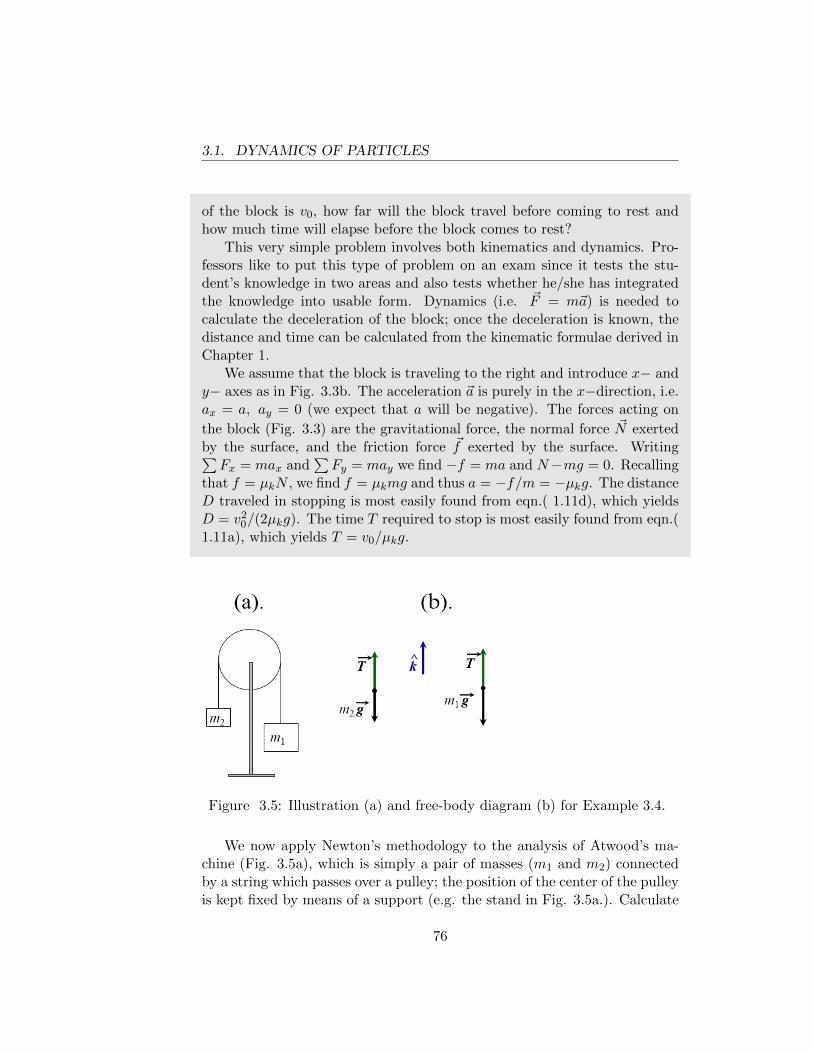
3.1. DYNAMICS OF PARTICLES
of the block is v0, how far will the block travel before coming to rest andhow much time will elapse before the block comes to rest?
This very simple problem involves both kinematics and dynamics. Pro-fessors like to put this type of problem on an exam since it tests the stu-dent’s knowledge in two areas and also tests whether he/she has integratedthe knowledge into usable form. Dynamics (i.e. ~F = m~a) is needed tocalculate the deceleration of the block; once the deceleration is known, thedistance and time can be calculated from the kinematic formulae derived inChapter 1.
We assume that the block is traveling to the right and introduce x− andy− axes as in Fig. 3.3b. The acceleration ~a is purely in the x−direction, i.e.ax = a, ay = 0 (we expect that a will be negative). The forces acting on
the block (Fig. 3.3) are the gravitational force, the normal force ~N exertedby the surface, and the friction force ~f exerted by the surface. Writing∑Fx = max and
∑Fy = may we find −f = ma and N−mg = 0. Recalling
that f = µkN , we find f = µkmg and thus a = −f/m = −µkg. The distanceD traveled in stopping is most easily found from eqn.( 1.11d), which yieldsD = v2
0/(2µkg). The time T required to stop is most easily found from eqn.(1.11a), which yields T = v0/µkg.
Figure 3.5: Illustration (a) and free-body diagram (b) for Example 3.4.
We now apply Newton’s methodology to the analysis of Atwood’s ma-chine (Fig. 3.5a), which is simply a pair of masses (m1 and m2) connectedby a string which passes over a pulley; the position of the center of the pulleyis kept fixed by means of a support (e.g. the stand in Fig. 3.5a.). Calculate
76
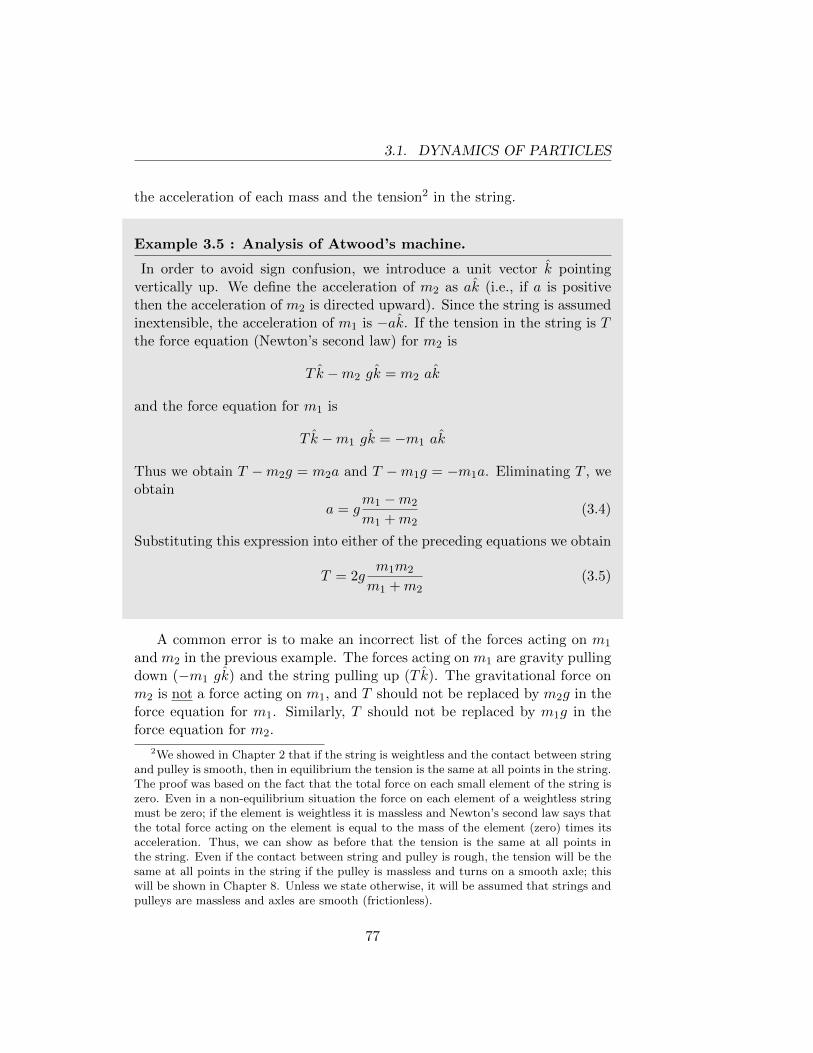
3.1. DYNAMICS OF PARTICLES
the acceleration of each mass and the tension2 in the string.
Example 3.5 : Analysis of Atwood’s machine.
In order to avoid sign confusion, we introduce a unit vector k pointingvertically up. We define the acceleration of m2 as ak (i.e., if a is positivethen the acceleration of m2 is directed upward). Since the string is assumedinextensible, the acceleration of m1 is −ak. If the tension in the string is Tthe force equation (Newton’s second law) for m2 is
T k −m2 gk = m2 ak
and the force equation for m1 is
T k −m1 gk = −m1 ak
Thus we obtain T −m2g = m2a and T −m1g = −m1a. Eliminating T , weobtain
a = gm1 −m2
m1 +m2(3.4)
Substituting this expression into either of the preceding equations we obtain
T = 2gm1m2
m1 +m2(3.5)
A common error is to make an incorrect list of the forces acting on m1
and m2 in the previous example. The forces acting on m1 are gravity pullingdown (−m1 gk) and the string pulling up (T k). The gravitational force onm2 is not a force acting on m1, and T should not be replaced by m2g in theforce equation for m1. Similarly, T should not be replaced by m1g in theforce equation for m2.
2We showed in Chapter 2 that if the string is weightless and the contact between stringand pulley is smooth, then in equilibrium the tension is the same at all points in the string.The proof was based on the fact that the total force on each small element of the string iszero. Even in a non-equilibrium situation the force on each element of a weightless stringmust be zero; if the element is weightless it is massless and Newton’s second law says thatthe total force acting on the element is equal to the mass of the element (zero) times itsacceleration. Thus, we can show as before that the tension is the same at all points inthe string. Even if the contact between string and pulley is rough, the tension will be thesame at all points in the string if the pulley is massless and turns on a smooth axle; thiswill be shown in Chapter 8. Unless we state otherwise, it will be assumed that strings andpulleys are massless and axles are smooth (frictionless).
77
3.1. DYNAMICS OF PARTICLES
One should acquire the habit of examining an answer to see whether itis “reasonable”. In particular, there are usually some special limiting casesin which we already know what the answer is and if our answer is correct itwill reduce to the expected value in these special cases. This procedure willusually enable us to discover algebraic errors as well as errors in reasoning.
In the previous example we expect that a = 0 if m1 = m2, a > 0 ifm1 > m2, and a < 0 if m1 < m2. Eqn.( 3.4) agrees with these expectations.Furthermore, ifm1 = m2 we have equilibrium and therefore expect T = m1g.Eqn.( 3.5) agrees with this expectation if we set m1 = m2. We also know theanswer, without calculation, in the special case when m1 is much larger thanm2. In this case we expect m1 to drop like a freely falling body, i.e. a = g.Indeed eqn.( 3.4) yields this result when m1 � m2 (we can neglect m2 inthe numerator and denominator) and also yields a = −g (as expected) whenm2 � m1. Furthermore, since m2 accelerates upward with acceleration gwhen m1 � m2, it follows that in this case the total force acting on m2 musthave magnitude m2g and must be directed upward. Therefore the tensionin the string must be 2m2g when m1 � m2. Eqn.( 3.5) confirms this sincem1/(m1 +m2) approaches 1 when m1 � m2.
Example 3.6 : Interaction of Atwood’s machine with the floor.
A question frequently asked about Example 3.5 is the following: whatupward force ~N does the ground exert on the stand? (Equivalently, if theentire apparatus is placed on a scale, what will the scale read?) If the entireapparatus were in equilibrium, we could immediately infer from Newton’sfirst law that ~N is equal in magnitude to the weight of the apparatus. Butm1 and m2 are accelerating and are therefore not in equilibrium.
At this point it is useful to extend Newton’s second law to compositesystems (consisting of more than one particle), just as we extended Newton’sfirst law. We simply write the equation ~Fi = mi~ai for each particle inour system (the index i enumerates the particles) and sum the resultingequations to obtain
∑i~Fi =
∑imi~ai. If we decompose ~Fi into an external
part and an internal part, just as we did in Chapter 2, the internal forcescancel in pairs as the result of Newton’s third law. Thus we obtain
~Fext =∑i
mi~ai (3.6)
where ~Fext is the total (i.e. the net or vector sum) external force on thesystem. If all particles of the system have the same acceleration ~a,
78
3.1. DYNAMICS OF PARTICLES
eqn.( 3.6) becomes~Fext = M~a (3.7)
where M is the total mass of the system.Let us apply eqn.( 3.6) to Atwood’s machine, taking the entire apparatus
(including the stand, which is assumed weightless) as our system. We cannotuse eqn.( 3.7) since different parts of the system have different accelerations.So we must use eqn.( 3.6). The only external forces on this system aregravity and the normal force exerted by the ground. Thus eqn.( 3.6) states
−m1gk −m2gk +Nk = m2ak −m1ak
which yields N = (m2 −m1)a+ (m1 +m2)g. Inserting our prior expressioneqn.( 3.4) for a and doing a little algebra, we find
N = 4gm1m2
m1 +m2(3.8)
If the stand is not weightless then the weight of the stand must be includedin the external force and will simply be added to the right side of eqn.( 3.8).Note that when m1 = m2 we find from eqn.( 3.8) that N = 2m1g, which iswhat we expect in equilibrium. If m1 6= m2, it follows from eqn.( 3.8) thatN < m1g +m2g. Thus, if the apparatus is placed on a scale, the scale willread less than the weight of the apparatus!
Although we calculated N by using the general theorem eqn.( 3.6), wecould also have found N by noting that the stand is in equilibrium. Theonly external forces on the stand are the two strings pulling downward, eachwith force T and the floor pushing up with force of magnitude N . Thus wefind N = 2T and using the expression eqn.( 3.5) for T we obtain eqn.( 3.8).
Example 3.7 : Analysis of a double pulley system.
Let us consider the pulley system shown in Fig. 3.6a. The pulleys aresmooth and massless. The position of pulley B is fixed, but A can move.We have already seen (Example 2.7) that if m1 = 1
2m2 the system will be in
equilibrium. If m1 and m2 are arbitrarily chosen, we want to calculate theaccelerations of both masses and the tension T in the string.
It is essential to recognize the relation between the acceleration of m2
and the acceleration of m1. Failure to understand this relation, which is an
79
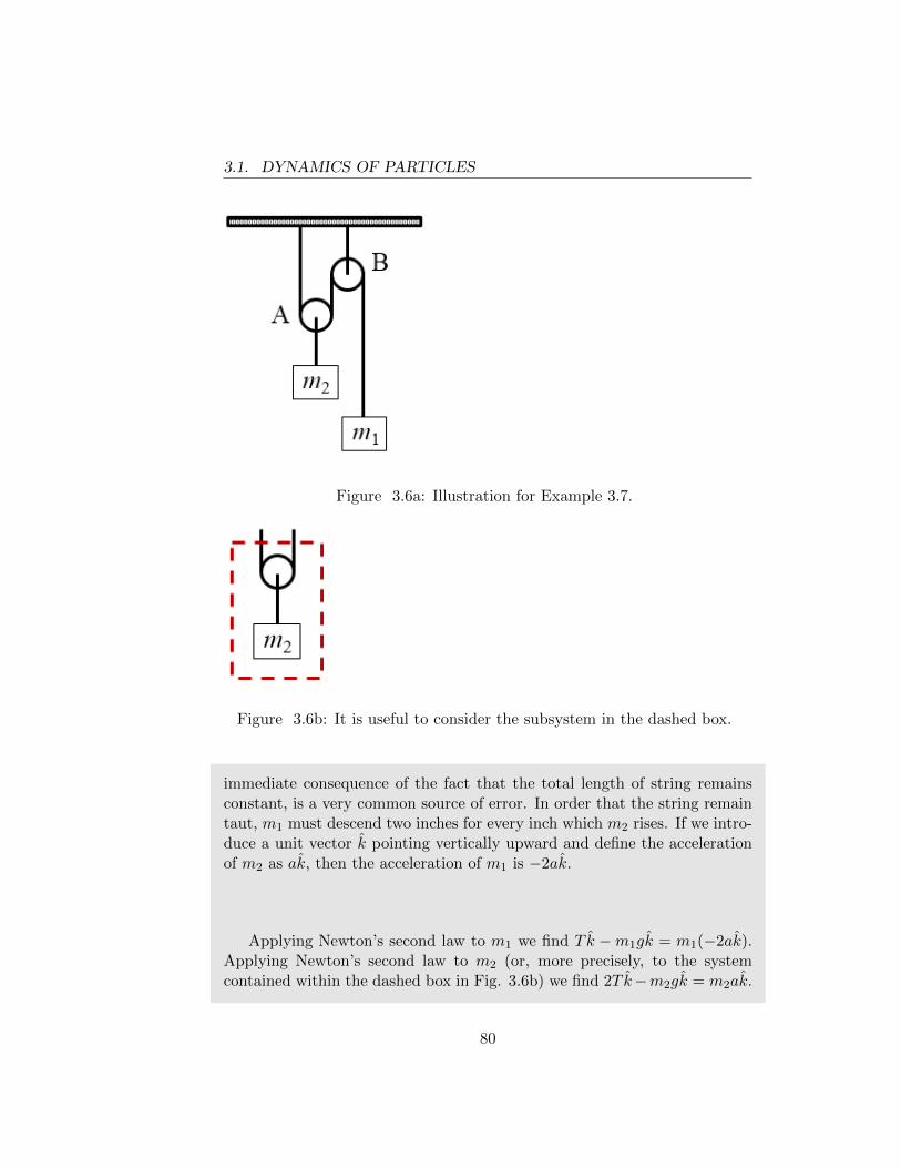
3.1. DYNAMICS OF PARTICLES
Figure 3.6a: Illustration for Example 3.7.
Figure 3.6b: It is useful to consider the subsystem in the dashed box.
immediate consequence of the fact that the total length of string remainsconstant, is a very common source of error. In order that the string remaintaut, m1 must descend two inches for every inch which m2 rises. If we intro-duce a unit vector k pointing vertically upward and define the accelerationof m2 as ak, then the acceleration of m1 is −2ak.
Applying Newton’s second law to m1 we find T k −m1gk = m1(−2ak).Applying Newton’s second law to m2 (or, more precisely, to the systemcontained within the dashed box in Fig. 3.6b) we find 2T k−m2gk = m2ak.
80

3.1. DYNAMICS OF PARTICLES
Solving these two simultaneous equations for a and T we find
a = g2m1 −m2
4m1 +m2
T = 3gm1m2
4m1 +m2.
When m1 = 12m2 we recover the solution the statics problem. The reader
should verify that the expressions for a and T reduce to the expected valueswhen m1 � m2 and when m2 � m1.
Figure 3.7: Illustration (a.) and free-body diagram (b.) for Example 3.8.
Example 3.8 : A simple accelerometer.
A mass m is suspended by a string from the ceiling of an acceleratingrailroad car (Fig. 3.7). The string makes a constant angle θ with the vertical.Calculate the acceleration of the railroad car.
Most students get the correct answer to this problem but many usedubious arguments which will surely lead to confusion when applied to morecomplicated situations. This is not a statics problem! The mass m is not inequilibrium; it has the same acceleration as the train. If we introduce axesattached to the ground (x-axis horizontal, y-axis vertical) then ax = a anday = 0. Fig. 3.7b shows the forces exerted on the mass m by the earth and
by the string. The x and y components of ~F = m~a yield
T sin θ = ma (3.9a)
81
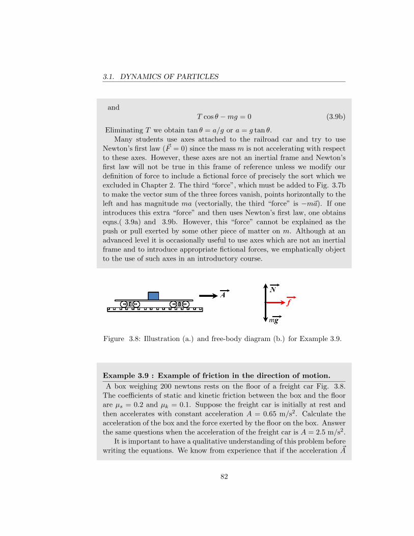
3.1. DYNAMICS OF PARTICLES
andT cos θ −mg = 0 (3.9b)
Eliminating T we obtain tan θ = a/g or a = g tan θ.Many students use axes attached to the railroad car and try to use
Newton’s first law (~F = 0) since the mass m is not accelerating with respectto these axes. However, these axes are not an inertial frame and Newton’sfirst law will not be true in this frame of reference unless we modify ourdefinition of force to include a fictional force of precisely the sort which weexcluded in Chapter 2. The third “force”, which must be added to Fig. 3.7bto make the vector sum of the three forces vanish, points horizontally to theleft and has magnitude ma (vectorially, the third “force” is −m~a). If oneintroduces this extra “force” and then uses Newton’s first law, one obtainseqns.( 3.9a) and 3.9b. However, this “force” cannot be explained as thepush or pull exerted by some other piece of matter on m. Although at anadvanced level it is occasionally useful to use axes which are not an inertialframe and to introduce appropriate fictional forces, we emphatically objectto the use of such axes in an introductory course.
Figure 3.8: Illustration (a.) and free-body diagram (b.) for Example 3.9.
Example 3.9 : Example of friction in the direction of motion.
A box weighing 200 newtons rests on the floor of a freight car Fig. 3.8.The coefficients of static and kinetic friction between the box and the floorare µs = 0.2 and µk = 0.1. Suppose the freight car is initially at rest andthen accelerates with constant acceleration A = 0.65 m/s2. Calculate theacceleration of the box and the force exerted by the floor on the box. Answerthe same questions when the acceleration of the freight car is A = 2.5 m/s2.
It is important to have a qualitative understanding of this problem beforewriting the equations. We know from experience that if the acceleration ~A
82
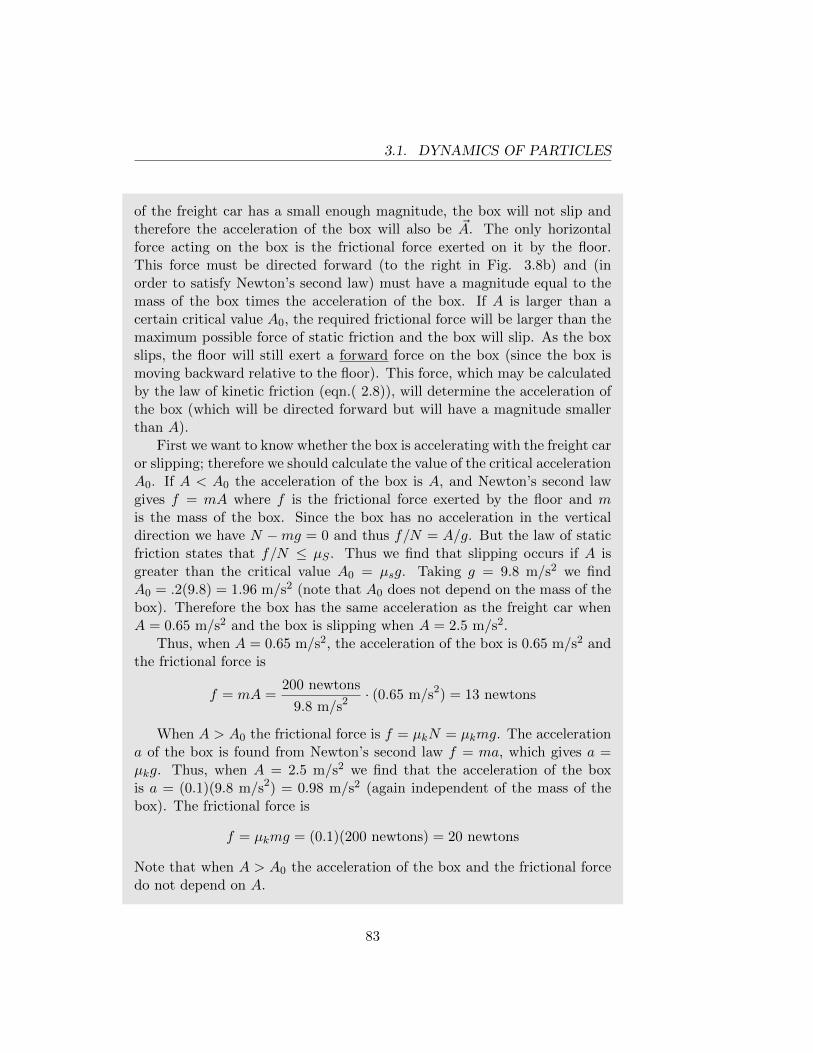
3.1. DYNAMICS OF PARTICLES
of the freight car has a small enough magnitude, the box will not slip andtherefore the acceleration of the box will also be ~A. The only horizontalforce acting on the box is the frictional force exerted on it by the floor.This force must be directed forward (to the right in Fig. 3.8b) and (inorder to satisfy Newton’s second law) must have a magnitude equal to themass of the box times the acceleration of the box. If A is larger than acertain critical value A0, the required frictional force will be larger than themaximum possible force of static friction and the box will slip. As the boxslips, the floor will still exert a forward force on the box (since the box ismoving backward relative to the floor). This force, which may be calculatedby the law of kinetic friction (eqn.( 2.8)), will determine the acceleration ofthe box (which will be directed forward but will have a magnitude smallerthan A).
First we want to know whether the box is accelerating with the freight caror slipping; therefore we should calculate the value of the critical accelerationA0. If A < A0 the acceleration of the box is A, and Newton’s second lawgives f = mA where f is the frictional force exerted by the floor and mis the mass of the box. Since the box has no acceleration in the verticaldirection we have N −mg = 0 and thus f/N = A/g. But the law of staticfriction states that f/N ≤ µS . Thus we find that slipping occurs if A isgreater than the critical value A0 = µsg. Taking g = 9.8 m/s2 we findA0 = .2(9.8) = 1.96 m/s2 (note that A0 does not depend on the mass of thebox). Therefore the box has the same acceleration as the freight car whenA = 0.65 m/s2 and the box is slipping when A = 2.5 m/s2.
Thus, when A = 0.65 m/s2, the acceleration of the box is 0.65 m/s2 andthe frictional force is
f = mA =200 newtons
9.8 m/s2 · (0.65 m/s2) = 13 newtons
When A > A0 the frictional force is f = µkN = µkmg. The accelerationa of the box is found from Newton’s second law f = ma, which gives a =µkg. Thus, when A = 2.5 m/s2 we find that the acceleration of the boxis a = (0.1)(9.8 m/s2) = 0.98 m/s2 (again independent of the mass of thebox). The frictional force is
f = µkmg = (0.1)(200 newtons) = 20 newtons
Note that when A > A0 the acceleration of the box and the frictional forcedo not depend on A.
83
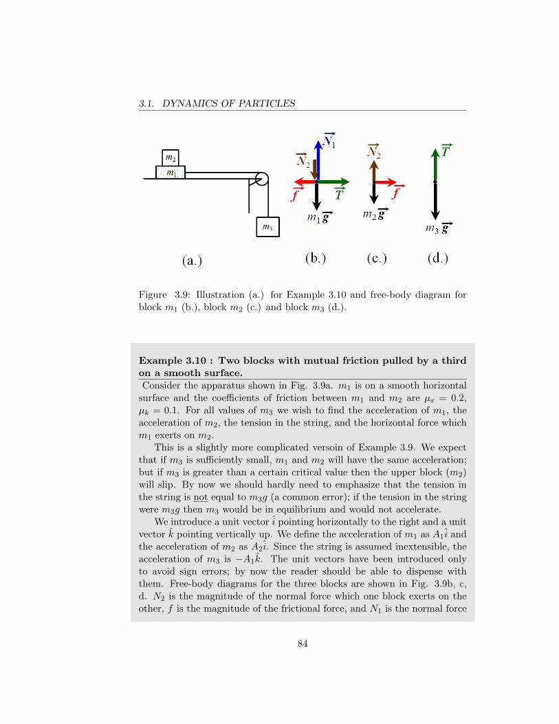
3.1. DYNAMICS OF PARTICLES
Figure 3.9: Illustration (a.) for Example 3.10 and free-body diagram forblock m1 (b.), block m2 (c.) and block m3 (d.).
Example 3.10 : Two blocks with mutual friction pulled by a thirdon a smooth surface.
Consider the apparatus shown in Fig. 3.9a. m1 is on a smooth horizontalsurface and the coefficients of friction between m1 and m2 are µs = 0.2,µk = 0.1. For all values of m3 we wish to find the acceleration of m1, theacceleration of m2, the tension in the string, and the horizontal force whichm1 exerts on m2.
This is a slightly more complicated versoin of Example 3.9. We expectthat if m3 is sufficiently small, m1 and m2 will have the same acceleration;but if m3 is greater than a certain critical value then the upper block (m2)will slip. By now we should hardly need to emphasize that the tension inthe string is not equal to m3g (a common error); if the tension in the stringwere m3g then m3 would be in equilibrium and would not accelerate.
We introduce a unit vector i pointing horizontally to the right and a unitvector k pointing vertically up. We define the acceleration of m1 as A1i andthe acceleration of m2 as A2i. Since the string is assumed inextensible, theacceleration of m3 is −A1k. The unit vectors have been introduced onlyto avoid sign errors; by now the reader should be able to dispense withthem. Free-body diagrams for the three blocks are shown in Fig. 3.9b, c,d. N2 is the magnitude of the normal force which one block exerts on theother, f is the magnitude of the frictional force, and N1 is the normal force
84
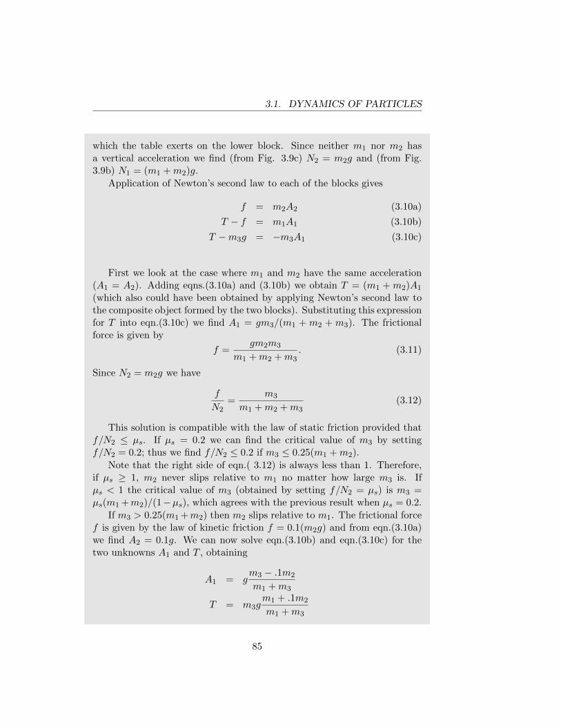
3.1. DYNAMICS OF PARTICLES
which the table exerts on the lower block. Since neither m1 nor m2 hasa vertical acceleration we find (from Fig. 3.9c) N2 = m2g and (from Fig.3.9b) N1 = (m1 +m2)g.
Application of Newton’s second law to each of the blocks gives
f = m2A2 (3.10a)
T − f = m1A1 (3.10b)
T −m3g = −m3A1 (3.10c)
First we look at the case where m1 and m2 have the same acceleration(A1 = A2). Adding eqns.(3.10a) and (3.10b) we obtain T = (m1 + m2)A1
(which also could have been obtained by applying Newton’s second law tothe composite object formed by the two blocks). Substituting this expressionfor T into eqn.(3.10c) we find A1 = gm3/(m1 + m2 + m3). The frictionalforce is given by
f =gm2m3
m1 +m2 +m3. (3.11)
Since N2 = m2g we have
f
N2=
m3
m1 +m2 +m3(3.12)
This solution is compatible with the law of static friction provided thatf/N2 ≤ µs. If µs = 0.2 we can find the critical value of m3 by settingf/N2 = 0.2; thus we find f/N2 ≤ 0.2 if m3 ≤ 0.25(m1 +m2).
Note that the right side of eqn.( 3.12) is always less than 1. Therefore,if µs ≥ 1, m2 never slips relative to m1 no matter how large m3 is. Ifµs < 1 the critical value of m3 (obtained by setting f/N2 = µs) is m3 =µs(m1 +m2)/(1−µs), which agrees with the previous result when µs = 0.2.
If m3 > 0.25(m1 +m2) then m2 slips relative to m1. The frictional forcef is given by the law of kinetic friction f = 0.1(m2g) and from eqn.(3.10a)we find A2 = 0.1g. We can now solve eqn.(3.10b) and eqn.(3.10c) for thetwo unknowns A1 and T , obtaining
A1 = gm3 − .1m2
m1 +m3
T = m3gm1 + .1m2
m1 +m3
85
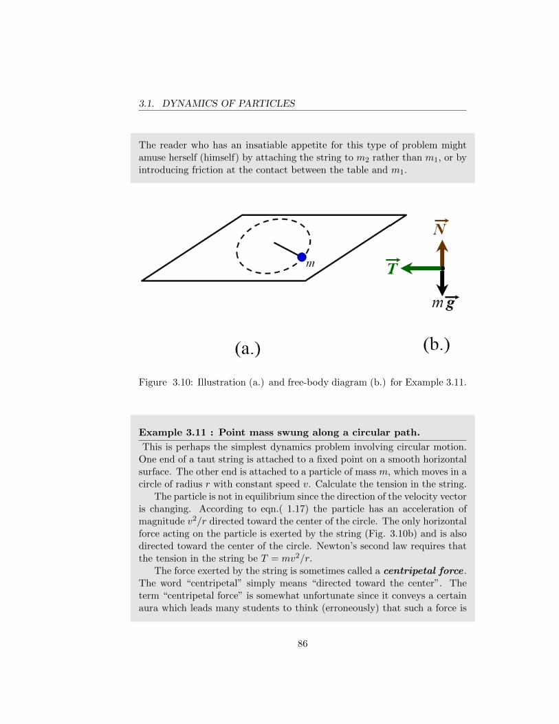
3.1. DYNAMICS OF PARTICLES
The reader who has an insatiable appetite for this type of problem mightamuse herself (himself) by attaching the string to m2 rather than m1, or byintroducing friction at the contact between the table and m1.
Figure 3.10: Illustration (a.) and free-body diagram (b.) for Example 3.11.
Example 3.11 : Point mass swung along a circular path.
This is perhaps the simplest dynamics problem involving circular motion.One end of a taut string is attached to a fixed point on a smooth horizontalsurface. The other end is attached to a particle of mass m, which moves in acircle of radius r with constant speed v. Calculate the tension in the string.
The particle is not in equilibrium since the direction of the velocity vectoris changing. According to eqn.( 1.17) the particle has an acceleration ofmagnitude v2/r directed toward the center of the circle. The only horizontalforce acting on the particle is exerted by the string (Fig. 3.10b) and is alsodirected toward the center of the circle. Newton’s second law requires thatthe tension in the string be T = mv2/r.
The force exerted by the string is sometimes called a centripetal force .The word “centripetal” simply means “directed toward the center”. Theterm “centripetal force” is somewhat unfortunate since it conveys a certainaura which leads many students to think (erroneously) that such a force is
86
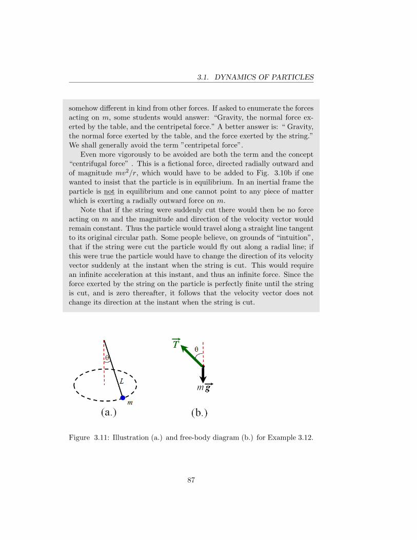
3.1. DYNAMICS OF PARTICLES
somehow different in kind from other forces. If asked to enumerate the forcesacting on m, some students would answer: “Gravity, the normal force ex-erted by the table, and the centripetal force.” A better answer is: “ Gravity,the normal force exerted by the table, and the force exerted by the string.”We shall generally avoid the term ”centripetal force”.
Even more vigorously to be avoided are both the term and the concept“centrifugal force” . This is a fictional force, directed radially outward andof magnitude mv2/r, which would have to be added to Fig. 3.10b if onewanted to insist that the particle is in equilibrium. In an inertial frame theparticle is not in equilibrium and one cannot point to any piece of matterwhich is exerting a radially outward force on m.
Note that if the string were suddenly cut there would then be no forceacting on m and the magnitude and direction of the velocity vector wouldremain constant. Thus the particle would travel along a straight line tangentto its original circular path. Some people believe, on grounds of “intuition”,that if the string were cut the particle would fly out along a radial line; ifthis were true the particle would have to change the direction of its velocityvector suddenly at the instant when the string is cut. This would requirean infinite acceleration at this instant, and thus an infinite force. Since theforce exerted by the string on the particle is perfectly finite until the stringis cut, and is zero thereafter, it follows that the velocity vector does notchange its direction at the instant when the string is cut.
Figure 3.11: Illustration (a.) and free-body diagram (b.) for Example 3.12.
87
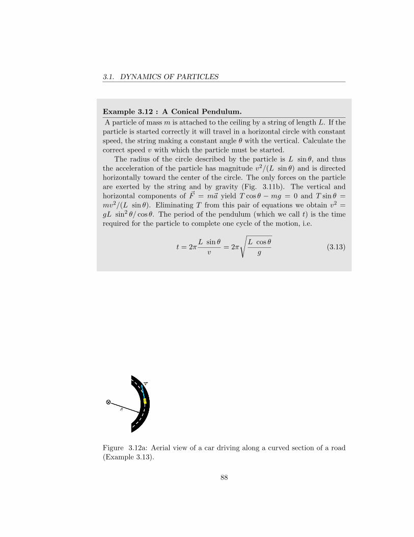
3.1. DYNAMICS OF PARTICLES
Example 3.12 : A Conical Pendulum.
A particle of mass m is attached to the ceiling by a string of length L. If theparticle is started correctly it will travel in a horizontal circle with constantspeed, the string making a constant angle θ with the vertical. Calculate thecorrect speed v with which the particle must be started.
The radius of the circle described by the particle is L sin θ, and thusthe acceleration of the particle has magnitude v2/(L sin θ) and is directedhorizontally toward the center of the circle. The only forces on the particleare exerted by the string and by gravity (Fig. 3.11b). The vertical andhorizontal components of ~F = m~a yield T cos θ − mg = 0 and T sin θ =mv2/(L sin θ). Eliminating T from this pair of equations we obtain v2 =gL sin2 θ/ cos θ. The period of the pendulum (which we call t) is the timerequired for the particle to complete one cycle of the motion, i.e.
t = 2πL sin θ
v= 2π
√L cos θ
g(3.13)
Figure 3.12a: Aerial view of a car driving along a curved section of a road(Example 3.13).
88
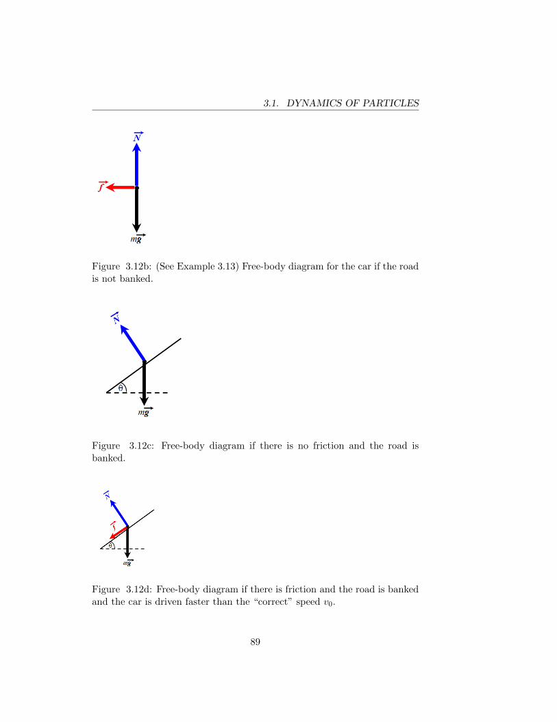
3.1. DYNAMICS OF PARTICLES
Figure 3.12b: (See Example 3.13) Free-body diagram for the car if the roadis not banked.
Figure 3.12c: Free-body diagram if there is no friction and the road isbanked.
Figure 3.12d: Free-body diagram if there is friction and the road is bankedand the car is driven faster than the “correct” speed v0.
89
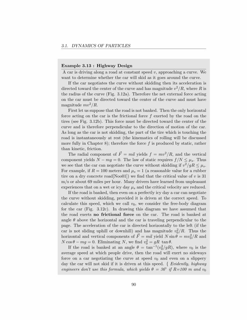
3.1. DYNAMICS OF PARTICLES
Example 3.13 : Highway Design
A car is driving along a road at constant speed v, approaching a curve. Wewant to determine whether the car will skid as it goes around the curve.
If the car negotiates the curve without skidding then its acceleration isdirected toward the center of the curve and has magnitude v2/R, where R isthe radius of the curve (Fig. 3.12a). Therefore the net external force actingon the car must be directed toward the center of the curve and must havemagnitude mv2/R.
First let us suppose that the road is not banked. Then the only horizontalforce acting on the car is the frictional force f exerted by the road on thetires (see Fig. 3.12b). This force must be directed toward the center of thecurve and is therefore perpendicular to the direction of motion of the car.As long as the car is not skidding, the part of the tire which is touching theroad is instantaneously at rest (the kinematics of rolling will be discussedmore fully in Chapter 8); therefore the force f is produced by static, ratherthan kinetic, friction.
The radial component of ~F = m~a yields f = mv2/R, and the verticalcomponent yields N −mg = 0. The law of static requires f/N ≤ µs. Thuswe see that the car can negotiate the curve without skidding if v2/gR ≤ µs.For example, if R = 100 meters and µs = 1 (a reasonable value for a rubbertire on a dry concrete road[Noo01]) we find that the critical value of v is 31m/s or about 69 miles per hour. Many drivers have learned from unpleasantexperiences that on a wet or icy day µs and the critical velocity are reduced.
If the road is banked, then even on a perfectly icy day a car can negotiatethe curve without skidding, provided it is driven at the correct speed. Tocalculate this speed, which we call v0, we consider the free-body diagramfor the car (Fig. 3.12c). In drawing this diagram we have assumed thatthe road exerts no frictional force on the car. The road is banked atangle θ above the horizontal and the car is traveling perpendicular to thepage. The acceleration of the car is directed horizontally to the left (if thecar is not sliding uphill or downhill) and has magnitude v2
0/R. Thus thehorizontal and vertical components of ~F = m~a yield N sin θ = mv2
0/R andN cos θ −mg = 0. Eliminating N , we find v2
0 = gR tan θ.If the road is banked at an angle θ = tan−1(v2
0/gR), where v0 is theaverage speed at which people drive, then the road will exert no sidewaysforce on a car negotiating the curve at speed v0 and even on a slipperyday the car will not skid if it is driven at this speed. { Evidently, highwayengineers don’t use this formula, which yields θ = 36◦ if R=100 m and v0
90
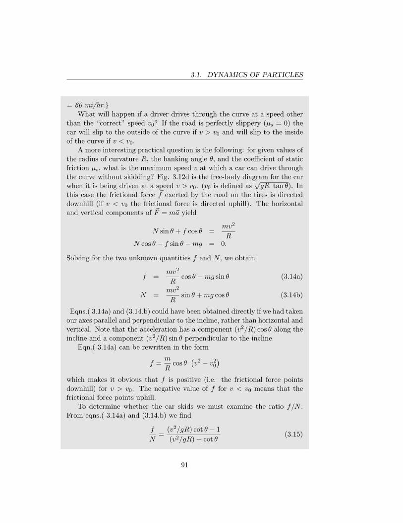
3.1. DYNAMICS OF PARTICLES
= 60 mi/hr.}What will happen if a driver drives through the curve at a speed other
than the “correct” speed v0? If the road is perfectly slippery (µs = 0) thecar will slip to the outside of the curve if v > v0 and will slip to the insideof the curve if v < v0.
A more interesting practical question is the following: for given values ofthe radius of curvature R, the banking angle θ, and the coefficient of staticfriction µs, what is the maximum speed v at which a car can drive throughthe curve without skidding? Fig. 3.12d is the free-body diagram for the carwhen it is being driven at a speed v > v0. (v0 is defined as
√gR tan θ). In
this case the frictional force ~f exerted by the road on the tires is directeddownhill (if v < v0 the frictional force is directed uphill). The horizontaland vertical components of ~F = m~a yield
N sin θ + f cos θ =mv2
RN cos θ − f sin θ −mg = 0.
Solving for the two unknown quantities f and N , we obtain
f =mv2
Rcos θ −mg sin θ (3.14a)
N =mv2
Rsin θ +mg cos θ (3.14b)
Eqns.( 3.14a) and (3.14.b) could have been obtained directly if we had takenour axes parallel and perpendicular to the incline, rather than horizontal andvertical. Note that the acceleration has a component (v2/R) cos θ along theincline and a component (v2/R) sin θ perpendicular to the incline.
Eqn.( 3.14a) can be rewritten in the form
f =m
Rcos θ
(v2 − v2
0
)which makes it obvious that f is positive (i.e. the frictional force pointsdownhill) for v > v0. The negative value of f for v < v0 means that thefrictional force points uphill.
To determine whether the car skids we must examine the ratio f/N .From eqns.( 3.14a) and (3.14.b) we find
f
N=
(v2/gR) cot θ − 1
(v2/gR) + cot θ(3.15)
91
3.1. DYNAMICS OF PARTICLES
A graph of the right side of eqn.( 3.15) for v > v0 is shown in Fig. 3.13.Note that f/N tends to the limiting value cot θ as v → ∞. If µs > cot θ,the ratio f/N will never exceed µs and the car will not skid no matter howfast it is driven. If µs < cot θ then f/N = µs when
v2
gR=µs cot θ + 1
cot θ − µs(3.16)
and the speed given by eqn.( 3.16) is the maximum speed with which thecar can be driven through the curve without skidding.
If we want to investigate the possibility of downhill skidding for v < v0,we should examine the ratio |f |/N (since f is negative in this case). Agraph of |f |/N for v < v0 is shown in Fig. 3.14. Note that the ratio |f |/Nis maximum when v = 0 and has the value tan θ. If µs > tan θ the car willnot skid downhill no matter how slowly it is driven. If µs < tan θ we obtainthe critical speed by setting |f |/N = µs and thus
v2
gR=
1− µs cot θ
µs + cot θ(3.17)
If the car is driven more slowly than the speed given by eqn.( 3.17), it willskid downhill.
If µs is larger than both tan θ and cot θ, the curve can be driven withoutskidding at any speed. This condition cannot be attained on an ordinaryroad since θ is quite small (and cot θ is very large) but can be attained ona raceway. For example, we could have µs = 1.2 and θ = 45◦. Note that ifR = 100 meters and the banking angle is 45◦ then the “correct” speed atwhich to drive the curve is√
gR tan θ = 31 m/s = 70 mi/hr.
At this speed the road will exert no sideways force on the tires and thestrain on mechanical components will be a minimum. A racing car willdrive through the curve at a speed considerably higher than the “correct”speed.
92
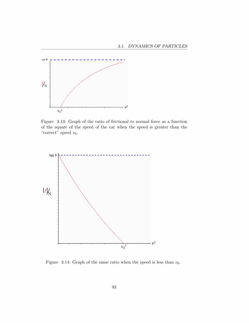
3.1. DYNAMICS OF PARTICLES
Figure 3.13: Graph of the ratio of frictional to normal force as a functionof the square of the speed of the car when the speed is greater than the“correct” speed v0.
Figure 3.14: Graph of the same ratio when the speed is less than v0.
93
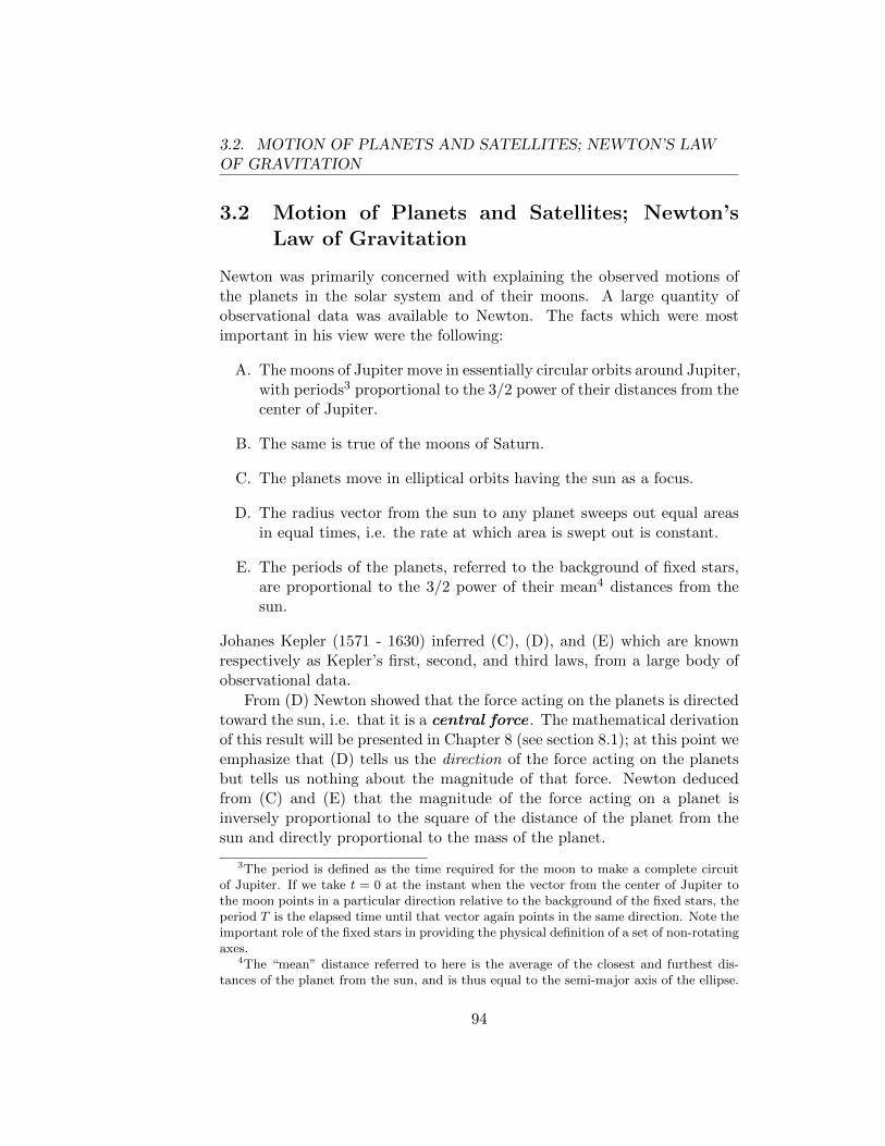
3.2. MOTION OF PLANETS AND SATELLITES; NEWTON’S LAWOF GRAVITATION
3.2 Motion of Planets and Satellites; Newton’sLaw of Gravitation
Newton was primarily concerned with explaining the observed motions ofthe planets in the solar system and of their moons. A large quantity ofobservational data was available to Newton. The facts which were mostimportant in his view were the following:
A. The moons of Jupiter move in essentially circular orbits around Jupiter,with periods3 proportional to the 3/2 power of their distances from thecenter of Jupiter.
B. The same is true of the moons of Saturn.
C. The planets move in elliptical orbits having the sun as a focus.
D. The radius vector from the sun to any planet sweeps out equal areasin equal times, i.e. the rate at which area is swept out is constant.
E. The periods of the planets, referred to the background of fixed stars,are proportional to the 3/2 power of their mean4 distances from thesun.
Johanes Kepler (1571 - 1630) inferred (C), (D), and (E) which are knownrespectively as Kepler’s first, second, and third laws, from a large body ofobservational data.
From (D) Newton showed that the force acting on the planets is directedtoward the sun, i.e. that it is a central force . The mathematical derivationof this result will be presented in Chapter 8 (see section 8.1); at this point weemphasize that (D) tells us the direction of the force acting on the planetsbut tells us nothing about the magnitude of that force. Newton deducedfrom (C) and (E) that the magnitude of the force acting on a planet isinversely proportional to the square of the distance of the planet from thesun and directly proportional to the mass of the planet.
3The period is defined as the time required for the moon to make a complete circuitof Jupiter. If we take t = 0 at the instant when the vector from the center of Jupiter tothe moon points in a particular direction relative to the background of the fixed stars, theperiod T is the elapsed time until that vector again points in the same direction. Note theimportant role of the fixed stars in providing the physical definition of a set of non-rotatingaxes.
4The “mean” distance referred to here is the average of the closest and furthest dis-tances of the planet from the sun, and is thus equal to the semi-major axis of the ellipse.
94
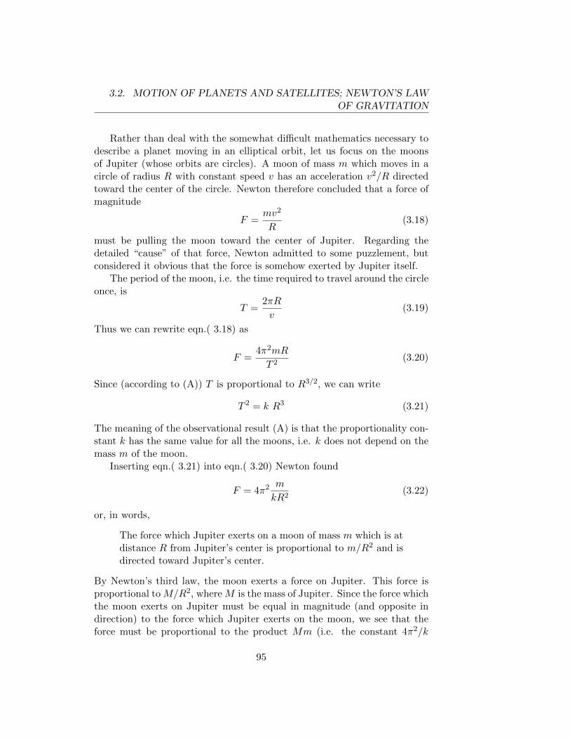
3.2. MOTION OF PLANETS AND SATELLITES; NEWTON’S LAWOF GRAVITATION
Rather than deal with the somewhat difficult mathematics necessary todescribe a planet moving in an elliptical orbit, let us focus on the moonsof Jupiter (whose orbits are circles). A moon of mass m which moves in acircle of radius R with constant speed v has an acceleration v2/R directedtoward the center of the circle. Newton therefore concluded that a force ofmagnitude
F =mv2
R(3.18)
must be pulling the moon toward the center of Jupiter. Regarding thedetailed “cause” of that force, Newton admitted to some puzzlement, butconsidered it obvious that the force is somehow exerted by Jupiter itself.
The period of the moon, i.e. the time required to travel around the circleonce, is
T =2πR
v(3.19)
Thus we can rewrite eqn.( 3.18) as
F =4π2mR
T 2(3.20)
Since (according to (A)) T is proportional to R3/2, we can write
T 2 = k R3 (3.21)
The meaning of the observational result (A) is that the proportionality con-stant k has the same value for all the moons, i.e. k does not depend on themass m of the moon.
Inserting eqn.( 3.21) into eqn.( 3.20) Newton found
F = 4π2 m
kR2(3.22)
or, in words,
The force which Jupiter exerts on a moon of mass m which is atdistance R from Jupiter’s center is proportional to m/R2 and isdirected toward Jupiter’s center.
By Newton’s third law, the moon exerts a force on Jupiter. This force isproportional to M/R2, where M is the mass of Jupiter. Since the force whichthe moon exerts on Jupiter must be equal in magnitude (and opposite indirection) to the force which Jupiter exerts on the moon, we see that theforce must be proportional to the product Mm (i.e. the constant 4π2/k
95
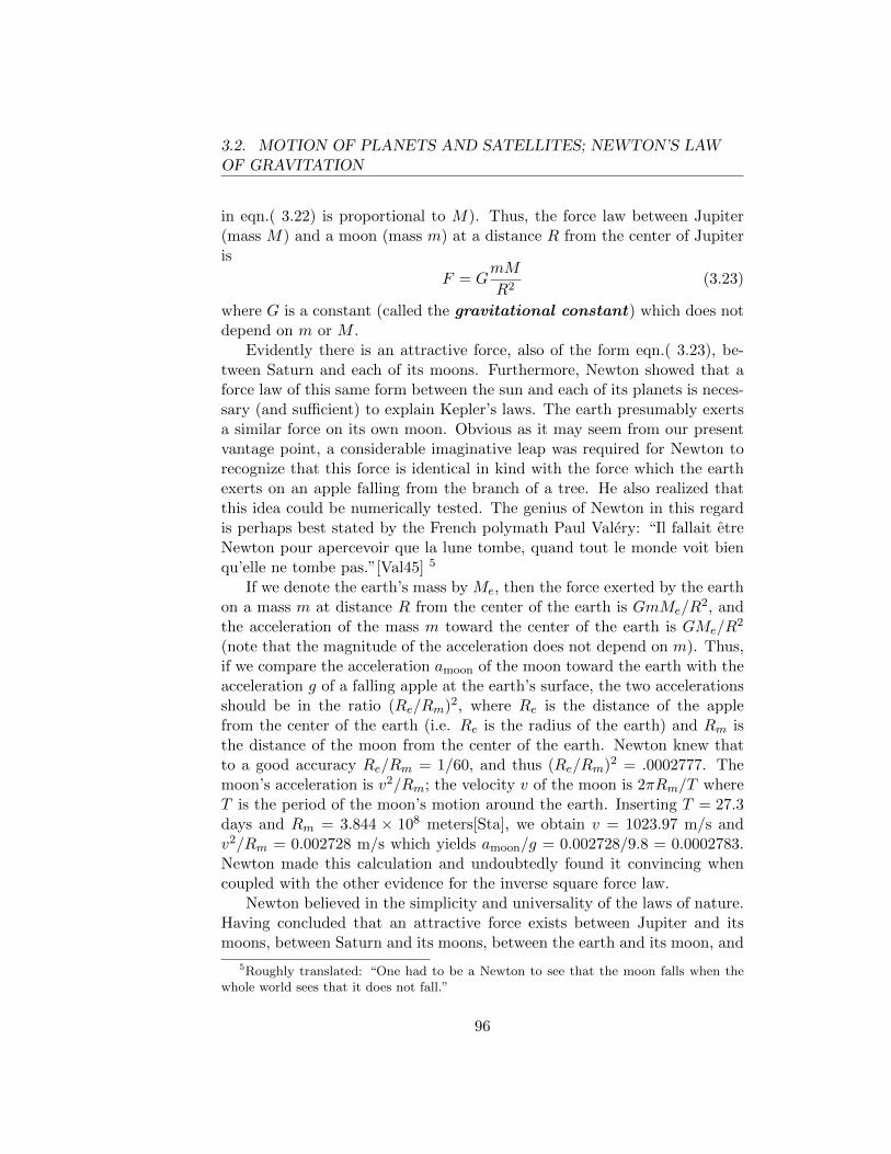
3.2. MOTION OF PLANETS AND SATELLITES; NEWTON’S LAWOF GRAVITATION
in eqn.( 3.22) is proportional to M). Thus, the force law between Jupiter(mass M) and a moon (mass m) at a distance R from the center of Jupiteris
F = GmM
R2(3.23)
where G is a constant (called the gravitational constant) which does notdepend on m or M .
Evidently there is an attractive force, also of the form eqn.( 3.23), be-tween Saturn and each of its moons. Furthermore, Newton showed that aforce law of this same form between the sun and each of its planets is neces-sary (and sufficient) to explain Kepler’s laws. The earth presumably exertsa similar force on its own moon. Obvious as it may seem from our presentvantage point, a considerable imaginative leap was required for Newton torecognize that this force is identical in kind with the force which the earthexerts on an apple falling from the branch of a tree. He also realized thatthis idea could be numerically tested. The genius of Newton in this regardis perhaps best stated by the French polymath Paul Valery: “Il fallait etreNewton pour apercevoir que la lune tombe, quand tout le monde voit bienqu’elle ne tombe pas.”[Val45] 5
If we denote the earth’s mass by Me, then the force exerted by the earthon a mass m at distance R from the center of the earth is GmMe/R
2, andthe acceleration of the mass m toward the center of the earth is GMe/R
2
(note that the magnitude of the acceleration does not depend on m). Thus,if we compare the acceleration amoon of the moon toward the earth with theacceleration g of a falling apple at the earth’s surface, the two accelerationsshould be in the ratio (Re/Rm)2, where Re is the distance of the applefrom the center of the earth (i.e. Re is the radius of the earth) and Rm isthe distance of the moon from the center of the earth. Newton knew thatto a good accuracy Re/Rm = 1/60, and thus (Re/Rm)2 = .0002777. Themoon’s acceleration is v2/Rm; the velocity v of the moon is 2πRm/T whereT is the period of the moon’s motion around the earth. Inserting T = 27.3days and Rm = 3.844 × 10⁸ meters[Sta], we obtain v = 1023.97 m/s andv2/Rm = 0.002728 m/s which yields amoon/g = 0.002728/9.8 = 0.0002783.Newton made this calculation and undoubtedly found it convincing whencoupled with the other evidence for the inverse square force law.
Newton believed in the simplicity and universality of the laws of nature.Having concluded that an attractive force exists between Jupiter and itsmoons, between Saturn and its moons, between the earth and its moon, and
5Roughly translated: “One had to be a Newton to see that the moon falls when thewhole world sees that it does not fall.”
96
3.2. MOTION OF PLANETS AND SATELLITES; NEWTON’S LAWOF GRAVITATION
between the sun and the planets, he then postulated that a similar attractiveforce (which he called gravitation) exists between any two bodies. Hepointed out that in everyday experience we are unaware of the gravitationalattraction between bodies because their mutual attractive force is so smallcompared with the gravitational force which the earth exerts on them. Hepostulated that any two particles (very small bodies) attract each other witha force of magnitude
F = GmM
r2(3.24)
directed from one particle to the other. In this equation m and M are themasses of the particles and r is the distance between them.
The question immediately arises: what force does a large spherical mass(like the earth) exert on a particle? If the distance of the particle from thecenter of the sphere is large compared with the radius of the sphere, thenthere will be at most a negligible error in using eqn.( 3.24), with r taken asthe distance from the center of the sphere to the particle. We have alreadyseen that there is strong evidence that eqn.( 3.24) is correct even when thedistance of the particle from the center of the sphere is not large comparedwith the radius of the sphere (for example, take the particle as Newton’sapple and the sphere as the earth), with r taken as the distance from thecenter of the sphere to the particle.
Newton recognized that if he assumed eqn.( 3.24) as the fundamentalforce law between particles, then it should be possible to calculate the forcebetween a particle and a spherical mass distribution by considering the dis-tribution as composed of many small elements (each of which exerts a forceon the particle given by eqn.( 3.24)) and adding up the forces which theseelements exert on the particle. He hoped that he would be able to showthat if the particle is outside the spherical mass distribution the force is thesame as if the entire mass distribution were replaced by a point mass (ofthe same total mass) at the center of the sphere. It is widely believed thathe delayed the publication of the Principia for twenty years until he had asatisfactory proof of this point.
The proof in the Principia is geometrical. We omit a proof here, but astudent who is familiar with integral calculus ought to be able to carry outthe calculation. The idea is to decompose the mass distribution into manysmall elements ∆M . The force exerted by ∆M on a particle of mass mhas magnitude Gm∆M/r2 where r is the distance between ∆M and m; thedirection of this force is along the line between ∆M and m. The total forceon m is found by vectorially adding the forces exerted on m by all the masselements ∆M (the sum of all the infinitesimal contributions is performed
97
3.2. MOTION OF PLANETS AND SATELLITES; NEWTON’S LAWOF GRAVITATION
by integration). Newton (who invented integral calculus although the firstcomplete published proofs came from Gottfried Leibniz) used a geometricalargument instead of integration in order not to overwhelm his readers. Westress that the proof (whether geometrical or by integration) depends heavilyon the fact that the force between particles varies inversely as the square ofthe distance. If the exponent were other than two, it would not be the casethat a spherical mass distribution produces the same gravitational effect asa point mass located at the center of the sphere.
A careful reader may have been disturbed by our discussion of the motionof the moon around the earth, and of Jupiter’s and Saturn’s moons aroundtheir respective planets. In each of these cases we employed Newton’s secondlaw in a frame of reference defined by axes which are non-rotating (with re-spect to the fixed stars) and whose origin moves with the center of the planetin question. Such axes are not an inertial frame since they are acceleratingwith respect to non-rotating axes whose origin is fixed in the sun.
The acceleration of these non-inertial axes is not negligible. For example,the earth’s acceleration in its approximately circular motion around the sunis more than twice as large as the moon’s acceleration relative to the earth (asthe reader can verify using the known ratio of distances of the earth from thesun and the moon, and of the month to the year). Nevertheless the discussionis essentially correct because, when we applied Newton’s second law (~F =m~a) to the moon, the only force which we considered was the gravitationalforce exerted by the earth on the moon. We omitted consideration of thegravitational force which the sun exerts on the moon. To a high degree ofaccuracy the sun exerts the same force per unit of mass on the moon andon the earth since the earth-moon distance is very small compared with theearth-sun distance. Therefore the sun produces the same acceleration ofboth the earth and the moon and their relative acceleration is due only tothe mutual gravitational forces between the earth and the moon. Similarremarks apply to Jupiter and its moons, and to Saturn and its moons.
Direct measurement of the proportionality constant G in the force laweqn.( 3.24) is difficult since the gravitational force is very small for exper-imentally accessible values of the masses and distance. The first accuratedetermination of G, obtained by direct measurement of the force betweentwo known masses at a known separation, was performed by Cavendish in1798[Ph.00]. The accepted value today isG = 6.67384×10⁻¹¹ m3 kg−1 s−2 =6.67384× 10⁻¹¹ N−m2/kg2[TN]. Since the acceleration g of a freely falling
98
3.2. MOTION OF PLANETS AND SATELLITES; NEWTON’S LAWOF GRAVITATION
body at the earth’s surface is given by
g = GMe
R2e
(3.25)
we can calculate the mass of the earth Me from the known values of g, G,and Re. One finds Me = 5.97× 1024 kg.
A century before Cavendish, Newton was able to make a reasonableestimate of G by guessing the average density of the earth. He guessed thatthe average density is between five and six times the density of water (“itis probable that the quantity of the whole matter of the earth may be fiveor six times greater than it if consisted all of water”[New02]). From theassumed value of the density and the known value of Re, Newton calculatedMe and thus G. In fact, Newton’s guess was remarkably good. The truedensity of the earth is 5.5 times that of water!
Example 3.14 : An artificial satellite’s orbit.
An artificial satellite is orbiting the earth in a circular orbit of radius R.Calculate the period T of the satellite.
(a). Evaluate T when R = 1.05 Re (just large enough to eliminate airresistance).
(b). Find the radius R of a synchronous orbit. A synchronous orbit, whichis used for a communications satellite, places the satellite in a circularorbit in a plane containing the equator, at a height such that thesatellite is always directly above the same point on the ground.
The force on the satellite, directed toward the center of the earth, isGmMe/R
2. The acceleration of the satellite is v2/R, directed toward thecenter of the earth. Therefore GmMe/R
2 = mv2/R. Inserting v = 2πR/Twe find
T 2 = 4π2 R3
GMe. (3.26)
Even if we did not know the values of G and Me we could evaluate the rightside of eqn.( 3.26) using eqn.( 3.25). We rewrite eqn.( 3.26) as
T 2 =
(4π2Reg
)·(R
Re
)3
(3.27)
99
3.2. MOTION OF PLANETS AND SATELLITES; NEWTON’S LAWOF GRAVITATION
Inserting Re = 6.3781× 10⁶ meters and g = 9.81 m/s2 we obtain
T = (84.44 minutes)(R/Re)3/2 (3.28)
If R/Re = 1.05, we find T = 91 minutes. For a synchronous orbit T =23.9 hours[MS82] (the period of the earth’s rotation relative to the distantstars otherwise known as the sidereal day), and thus we find R/Re)
3/2 =16.97 and R/Re = 6.60. The student should calculate the speed (in metersper second) of a satellite in each of these orbits.
100
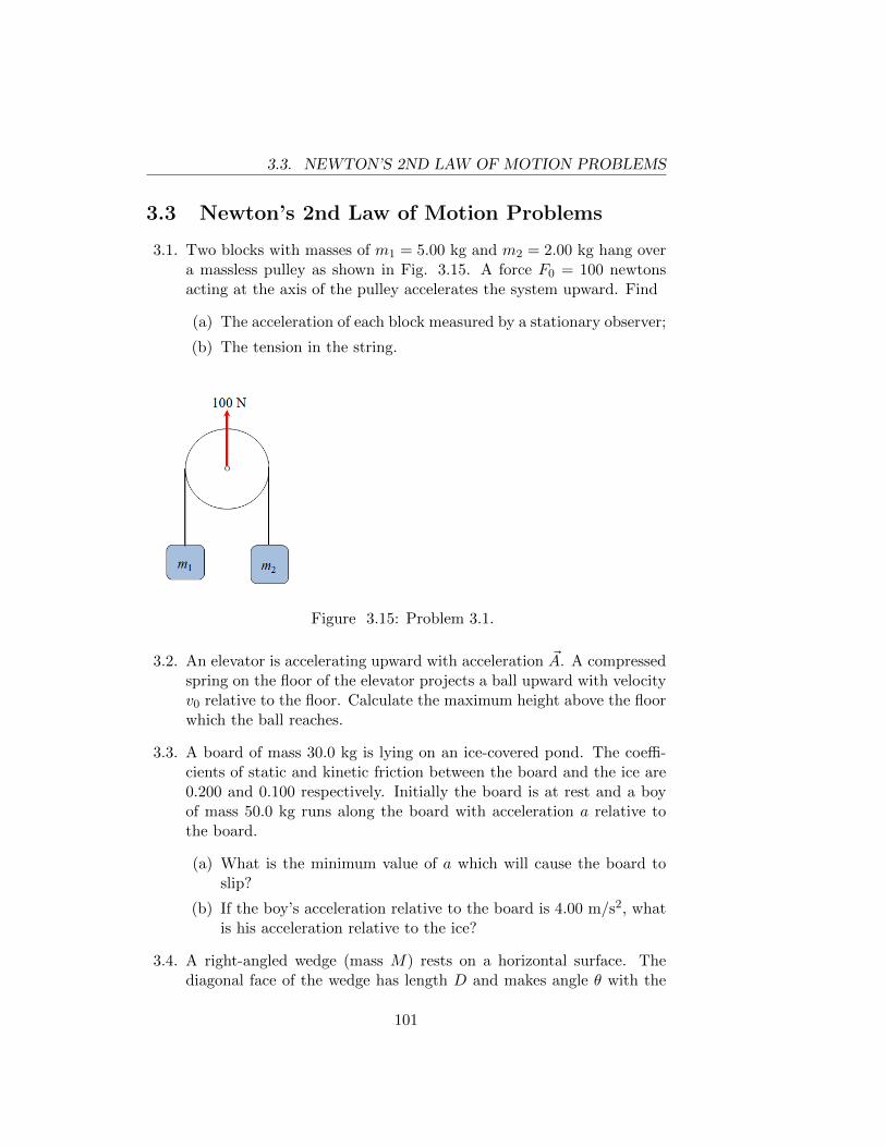
3.3. NEWTON’S 2ND LAW OF MOTION PROBLEMS
3.3 Newton’s 2nd Law of Motion Problems
3.1. Two blocks with masses of m1 = 5.00 kg and m2 = 2.00 kg hang overa massless pulley as shown in Fig. 3.15. A force F0 = 100 newtonsacting at the axis of the pulley accelerates the system upward. Find
(a) The acceleration of each block measured by a stationary observer;
(b) The tension in the string.
Figure 3.15: Problem 3.1.
3.2. An elevator is accelerating upward with acceleration ~A. A compressedspring on the floor of the elevator projects a ball upward with velocityv0 relative to the floor. Calculate the maximum height above the floorwhich the ball reaches.
3.3. A board of mass 30.0 kg is lying on an ice-covered pond. The coeffi-cients of static and kinetic friction between the board and the ice are0.200 and 0.100 respectively. Initially the board is at rest and a boyof mass 50.0 kg runs along the board with acceleration a relative tothe board.
(a) What is the minimum value of a which will cause the board toslip?
(b) If the boy’s acceleration relative to the board is 4.00 m/s2, whatis his acceleration relative to the ice?
3.4. A right-angled wedge (mass M) rests on a horizontal surface. Thediagonal face of the wedge has length D and makes angle θ with the
101
3.3. NEWTON’S 2ND LAW OF MOTION PROBLEMS
ground. All surfaces of the wedge are smooth. A block of mass mand negligible size is initially at the high end of the diagonal, and thewedge and block are initially at rest. The block then slides down thewedge, which recoils.
(a) How far from its initial position is the wedge when the block hitsthe ground?
(b) (harder)How much time did it take the block to slide down thewedge?
3.5. A closed rectangular box slides down a smooth inclined plane whichmakes an angle θ with the horizontal. A point mass m hangs by astring from the ceiling of the box.
(a) Calculate the angle α between the string and the normal to theceiling. Does the string hang on the downhill or uphill side of thenormal?
(b) Now suppose that there is a coefficient of kinetic friction µ be-tween the box and the plane. Calculate α. (The string couldoscillate but we are interested in the constant value of α whenthe box slides for a long time.)
3.6. A phonograph turntable rotates at 33 rpm (revolutions per minute).A coin placed on the turntable less than 15 cm from the center willnot slip and will rotate with the turntable, but it will slip if it is morethan 15 cm from the center. Calculate the coefficient of static frictionbetween the coin and the turntable.
3.7. Kepler found that the squares of the periods of the planets are propor-tional to the cubes of the radii of their orbits around the sun (assumecircular orbits). From this fact Newton deduced that the force be-tween the sun and a planet is proportional to the inverse square of themutual distance. Suppose Kepler had found that the squares of theperiods are proportional to the n-th power of the radii of the orbits.What force law would Newton have inferred?
3.8. Example 5.4 concerns a sled going down a hill and continuing on ahorizontal field, with a coefficient of kinetic friction µ between the sledand the snow. In Chapter 5 we use energy considerations to analyzethis system, but you can (and should) also solve Example 5.4 by usingNewton’s second law and simple kinematics. In our description of
102
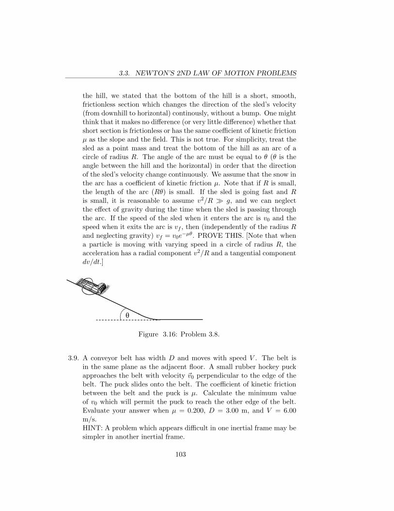
3.3. NEWTON’S 2ND LAW OF MOTION PROBLEMS
the hill, we stated that the bottom of the hill is a short, smooth,frictionless section which changes the direction of the sled’s velocity(from downhill to horizontal) continously, without a bump. One mightthink that it makes no difference (or very little difference) whether thatshort section is frictionless or has the same coefficient of kinetic frictionµ as the slope and the field. This is not true. For simplicity, treat thesled as a point mass and treat the bottom of the hill as an arc of acircle of radius R. The angle of the arc must be equal to θ (θ is theangle between the hill and the horizontal) in order that the directionof the sled’s velocity change continuously. We assume that the snow inthe arc has a coefficient of kinetic friction µ. Note that if R is small,the length of the arc (Rθ) is small. If the sled is going fast and Ris small, it is reasonable to assume v2/R � g, and we can neglectthe effect of gravity during the time when the sled is passing throughthe arc. If the speed of the sled when it enters the arc is v0 and thespeed when it exits the arc is vf , then (independently of the radius Rand neglecting gravity) vf = v0e
−µθ. PROVE THIS. [Note that whena particle is moving with varying speed in a circle of radius R, theacceleration has a radial component v2/R and a tangential componentdv/dt.]
θ
Figure 3.16: Problem 3.8.
3.9. A conveyor belt has width D and moves with speed V . The belt isin the same plane as the adjacent floor. A small rubber hockey puckapproaches the belt with velocity ~v0 perpendicular to the edge of thebelt. The puck slides onto the belt. The coefficient of kinetic frictionbetween the belt and the puck is µ. Calculate the minimum valueof v0 which will permit the puck to reach the other edge of the belt.Evaluate your answer when µ = 0.200, D = 3.00 m, and V = 6.00m/s.HINT: A problem which appears difficult in one inertial frame may besimpler in another inertial frame.
103
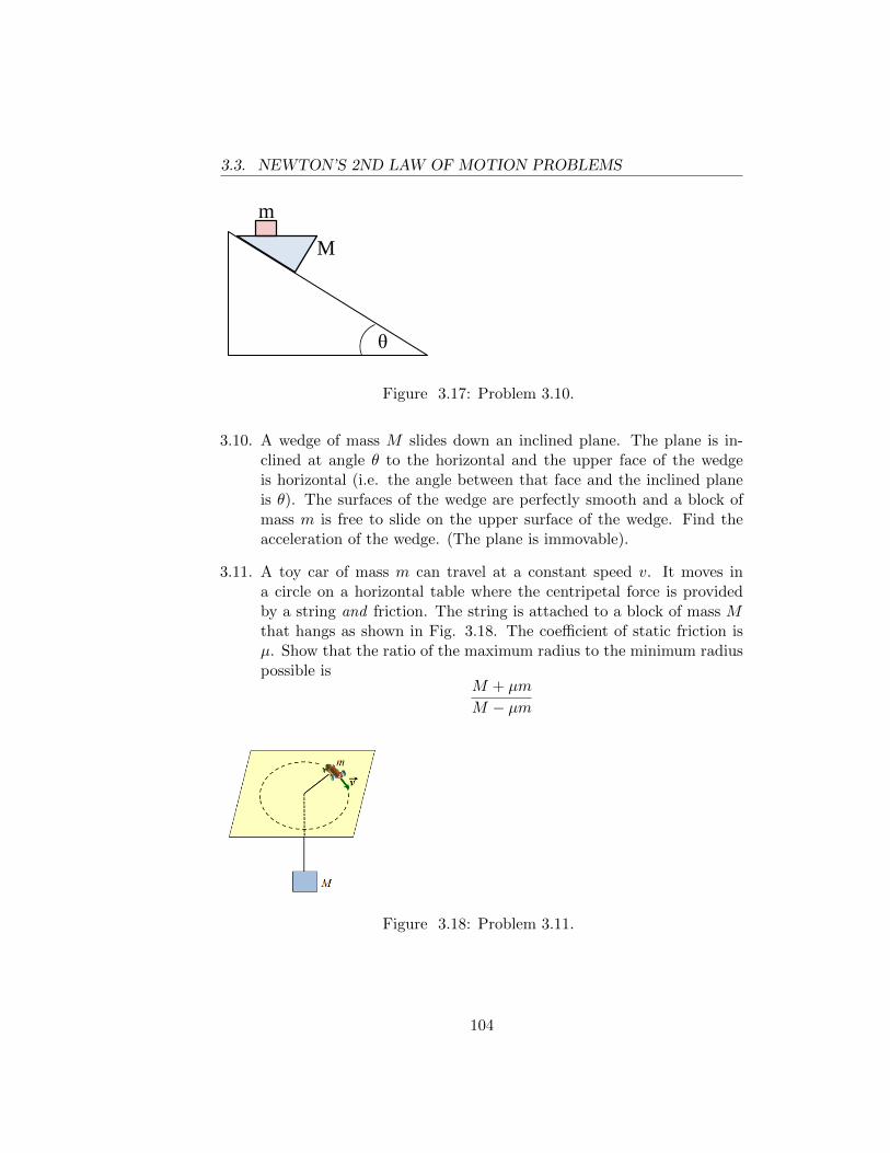
3.3. NEWTON’S 2ND LAW OF MOTION PROBLEMS
θ
M
m
Figure 3.17: Problem 3.10.
3.10. A wedge of mass M slides down an inclined plane. The plane is in-clined at angle θ to the horizontal and the upper face of the wedgeis horizontal (i.e. the angle between that face and the inclined planeis θ). The surfaces of the wedge are perfectly smooth and a block ofmass m is free to slide on the upper surface of the wedge. Find theacceleration of the wedge. (The plane is immovable).
3.11. A toy car of mass m can travel at a constant speed v. It moves ina circle on a horizontal table where the centripetal force is providedby a string and friction. The string is attached to a block of mass Mthat hangs as shown in Fig. 3.18. The coefficient of static friction isµ. Show that the ratio of the maximum radius to the minimum radiuspossible is
M + µm
M − µm
Figure 3.18: Problem 3.11.
104
Chapter 4
CONSERVATION ANDNON-CONSERVATION OFMOMENTUM
4.1 PRINCIPLE OF CONSERVATION OF MO-MENTUM
The only laws of classical mechanics are Newton’s laws. All other “laws”or general principles are deduced from Newton’s laws. The physicist isespecially interested in statements about the behavior of systems which donot depend on the detailed nature of the forces which are involved. Thebest-known example of such a statement is the Principle of Conservation ofMomentum:
If a system is subject to no external forces, the total momentumof the system remains constant in time.
To understand this statement we must, of course, first define “momen-tum”. If a particle of mass m has velocity ~v, the momentum of the particle(usually denoted by the vector ~p) is defined by
~p = m~v
105
4.1. PRINCIPLE OF CONSERVATION OF MOMENTUM
The momentum of a system of particles is defined as the sum of the momentaof the individual particles
~P =∑i
~pi =∑i
mi~vi
In Chapter 3 we proved (eqn.( 3.6)) that for any system
~Fext =∑i
mi~ai =d
dt
(∑i
mi~vi
)=d~P
dt(4.1)
where ~Fext is the total external force acting on the system.To derive eqn.( 4.1) we added up the force equations for all the particles
in the system; the internal forces canceled out in pairs as a consequence ofNewton’s third law.
If ~Fext = 0 we have
d~P
dt= 0⇒ ~P = constant (4.2)
which is the Principle of Conservation of Momentum .
Example 4.1 : Analysis of a collision in which bodies stick together.
A body of mass 1 kg and a body of mass 2 kg collide on a smooth horizontalsurface. Before the collision the 1 kg body has velocity 3 m/s directed duenorth and the 2 kg body has velocity 5 m/s directed northeast (i.e. 45◦ eastof due north). The two bodies stick together, forming a body of mass 3 kg.Find the magnitude and direction of the velocity of the 3 kg body.
We orient our axes so that the x-axis points east, the y-axis points north,and the z-axis is perpendicular to the surface. We define our system as thetwo bodies. Because the surface is smooth there is no external force in thex− or y−direction (note that there are internal forces in the system sincethe two bodies exert forces on each other during the time when they arecolliding). Gravity exerts a force in the z−direction on each body, but thenormal force exerted by the surface is equal in magnitude and opposite indirection to the gravitational force. Thus there is no net external force onthe system and we can apply the Principle of Conservation of Momentumwhich states (∑
mi~vi
)initial
=(∑
mi~vi
)final
(4.3)
106
4.1. PRINCIPLE OF CONSERVATION OF MOMENTUM
Note that eqn.( 4.3) is a vector equation, equivalent to the three equations(∑mivi, x
)initial
=(∑
mivi, x
)final
(4.4a)(∑mivi, y
)initial
=(∑
mivi, y
)final
(4.4b)(∑mivi, z
)initial
=(∑
mivi, z
)final
(4.4c)
A common error is to think that eqn.( 4.3) implies(∑mivi
)initial
=(∑
mivi
)final
where vi is the magnitude of the velocity vector ~vi. This does not followfrom eqn.( 4.3) and is not, in general, true.
In the present example eqn.(4.4c) is uninteresting, merely stating that0 = 0. If we call the unknown final velocity vector ~V , with components Vxand Vy, then eqn.(4.4a) and eqn.(4.4b) imply
2(5)(.707) + 0 = 3Vx
2(5)(.707) + 1(3) = 3Vy.
Thus we find Vx = 2.36 m/s, Vy = 3.36 m/s. The speed of the 3 kg body is
V =√V 2x + V 2
y = 4.10 m/s. The velocity vector V is directed 55◦ north of
east (tan−1 Vy/Vx = 55◦).
107
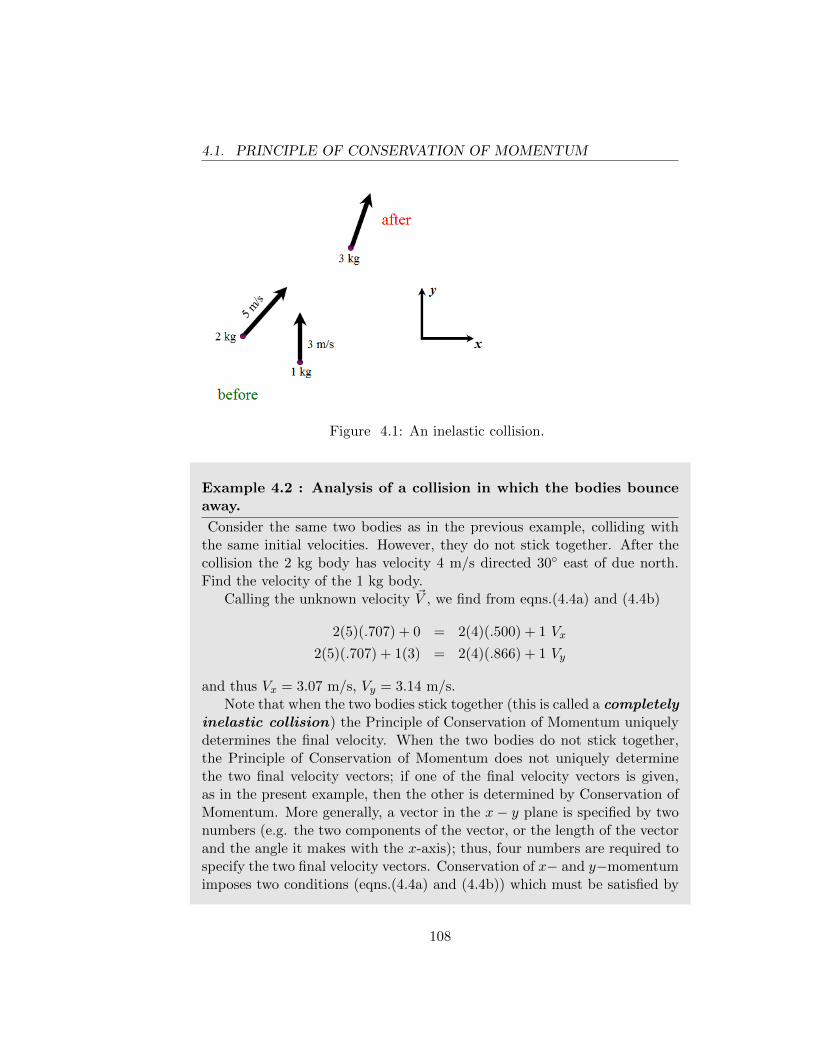
4.1. PRINCIPLE OF CONSERVATION OF MOMENTUM
Figure 4.1: An inelastic collision.
Example 4.2 : Analysis of a collision in which the bodies bounceaway.
Consider the same two bodies as in the previous example, colliding withthe same initial velocities. However, they do not stick together. After thecollision the 2 kg body has velocity 4 m/s directed 30◦ east of due north.Find the velocity of the 1 kg body.
Calling the unknown velocity ~V , we find from eqns.(4.4a) and (4.4b)
2(5)(.707) + 0 = 2(4)(.500) + 1 Vx
2(5)(.707) + 1(3) = 2(4)(.866) + 1 Vy
and thus Vx = 3.07 m/s, Vy = 3.14 m/s.Note that when the two bodies stick together (this is called a completely
inelastic collision) the Principle of Conservation of Momentum uniquelydetermines the final velocity. When the two bodies do not stick together,the Principle of Conservation of Momentum does not uniquely determinethe two final velocity vectors; if one of the final velocity vectors is given,as in the present example, then the other is determined by Conservation ofMomentum. More generally, a vector in the x− y plane is specified by twonumbers (e.g. the two components of the vector, or the length of the vectorand the angle it makes with the x-axis); thus, four numbers are required tospecify the two final velocity vectors. Conservation of x− and y−momentumimposes two conditions (eqns.(4.4a) and (4.4b)) which must be satisfied by
108
4.1. PRINCIPLE OF CONSERVATION OF MOMENTUM
these four numbers. Accordingly, the final state will be determined if anytwo of these numbers (e.g. the directions of the two final velocities) arespecified. The multiplicity of possible final states corresponds to the factthat the bodies have shapes (and the contact may take place at variouspoints on their surfaces) and various degrees of “squishiness” (e.g. two steelballs vs. two old tennis balls).
We now consider a skyrocket fired vertically from the ground. At theinstant when it is rising with velocity 100 m/s it explodes into three frag-ments of equal mass. Just after the explosion one fragment has velocity 50m/s directed vertically downward and another fragment has velocity 75 m/sdirected horizontally. Find the velocity vector of the third fragment justafter the explosion.
DIGRESSION (FAIRLY IMPORTANT): Most studentswill immediately solve this problem by equating the momentumof the skyrocket just before the explosion to the sum of the mo-menta of the fragments just after the explosion. This procedureis correct but requires some discussion since the system is notfree of external forces; gravity acts on the skyrocket and also onthe fragments. How do we justify neglecting the effect of grav-ity? If we integrate both sides of eqn.( 4.1) with respect to timefrom t1 to t2, where t1 and t2 are arbitrary, we obtain
∫ t2
t1
~Fext dt =
∫ t2
t1
d~P
dtdt = ~P (t2)− ~P (t1) (4.5)
Let us choose t1 as a time just before the explosion and t2 just af-ter the explosion. In this problem ~Fext = −Mgk where M is thetotal mass of the system and k is a unit vector directed verticallyupward. Then the left side of eqn.( 4.5) becomes −Mgk(t2− t1).An “ideal” explosion is one in which the skyrocket flies apart inan infinitesimal time, i.e. t2 − t1 → 0. In this case the left sideof eqn.( 4.5) vanishes or is negligible, and thus the momentumjust after the explosion is equal to the momentum just beforethe explosion.
109
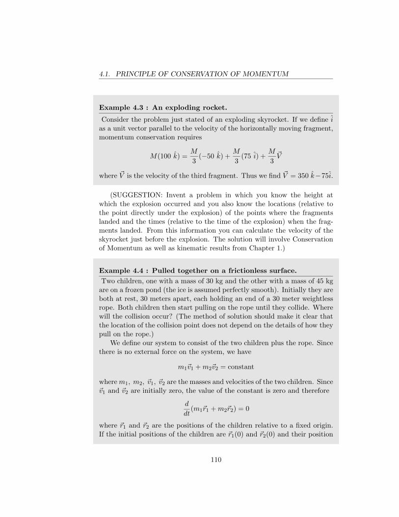
4.1. PRINCIPLE OF CONSERVATION OF MOMENTUM
Example 4.3 : An exploding rocket.
Consider the problem just stated of an exploding skyrocket. If we define ias a unit vector parallel to the velocity of the horizontally moving fragment,momentum conservation requires
M(100 k) =M
3(−50 k) +
M
3(75 i) +
M
3~V
where ~V is the velocity of the third fragment. Thus we find ~V = 350 k−75i.
(SUGGESTION: Invent a problem in which you know the height atwhich the explosion occurred and you also know the locations (relative tothe point directly under the explosion) of the points where the fragmentslanded and the times (relative to the time of the explosion) when the frag-ments landed. From this information you can calculate the velocity of theskyrocket just before the explosion. The solution will involve Conservationof Momentum as well as kinematic results from Chapter 1.)
Example 4.4 : Pulled together on a frictionless surface.
Two children, one with a mass of 30 kg and the other with a mass of 45 kgare on a frozen pond (the ice is assumed perfectly smooth). Initially they areboth at rest, 30 meters apart, each holding an end of a 30 meter weightlessrope. Both children then start pulling on the rope until they collide. Wherewill the collision occur? (The method of solution should make it clear thatthe location of the collision point does not depend on the details of how theypull on the rope.)
We define our system to consist of the two children plus the rope. Sincethere is no external force on the system, we have
m1~v1 +m2~v2 = constant
where m1, m2, ~v1, ~v2 are the masses and velocities of the two children. Since~v1 and ~v2 are initially zero, the value of the constant is zero and therefore
d
dt(m1~r1 +m2~r2) = 0
where ~r1 and ~r2 are the positions of the children relative to a fixed origin.If the initial positions of the children are ~r1(0) and ~r2(0) and their position
110
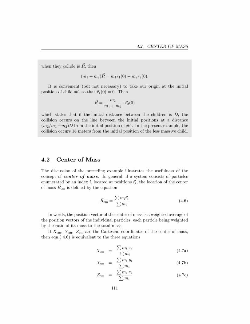
4.2. CENTER OF MASS
when they collide is ~R, then
(m1 +m2)~R = m1~r1(0) +m2~r2(0).
It is convenient (but not necessary) to take our origin at the initialposition of child #1 so that ~r1(0) = 0. Then
~R =m2
m1 +m2· ~r2(0)
which states that if the initial distance between the children is D, thecollision occurs on the line between the initial positions at a distance(m2/m1 +m2)D from the initial position of #1. In the present example, thecollision occurs 18 meters from the initial position of the less massive child.
4.2 Center of Mass
The discussion of the preceding example illustrates the usefulness of theconcept of center of mass. In general, if a system consists of particlesenumerated by an index i, located at positions ~ri, the location of the centerof mass ~Rcm is defined by the equation
~Rcm =
∑mi~ri∑mi
(4.6)
In words, the position vector of the center of mass is a weighted average ofthe position vectors of the individual particles, each particle being weightedby the ratio of its mass to the total mass.
If Xcm, Ycm, Zcm are the Cartesian coordinates of the center of mass,then eqn.( 4.6) is equivalent to the three equations
Xcm =
∑mi xi∑mi
(4.7a)
Ycm =
∑mi yi∑mi
(4.7b)
Zcm =
∑mi zi∑mi
(4.7c)
111
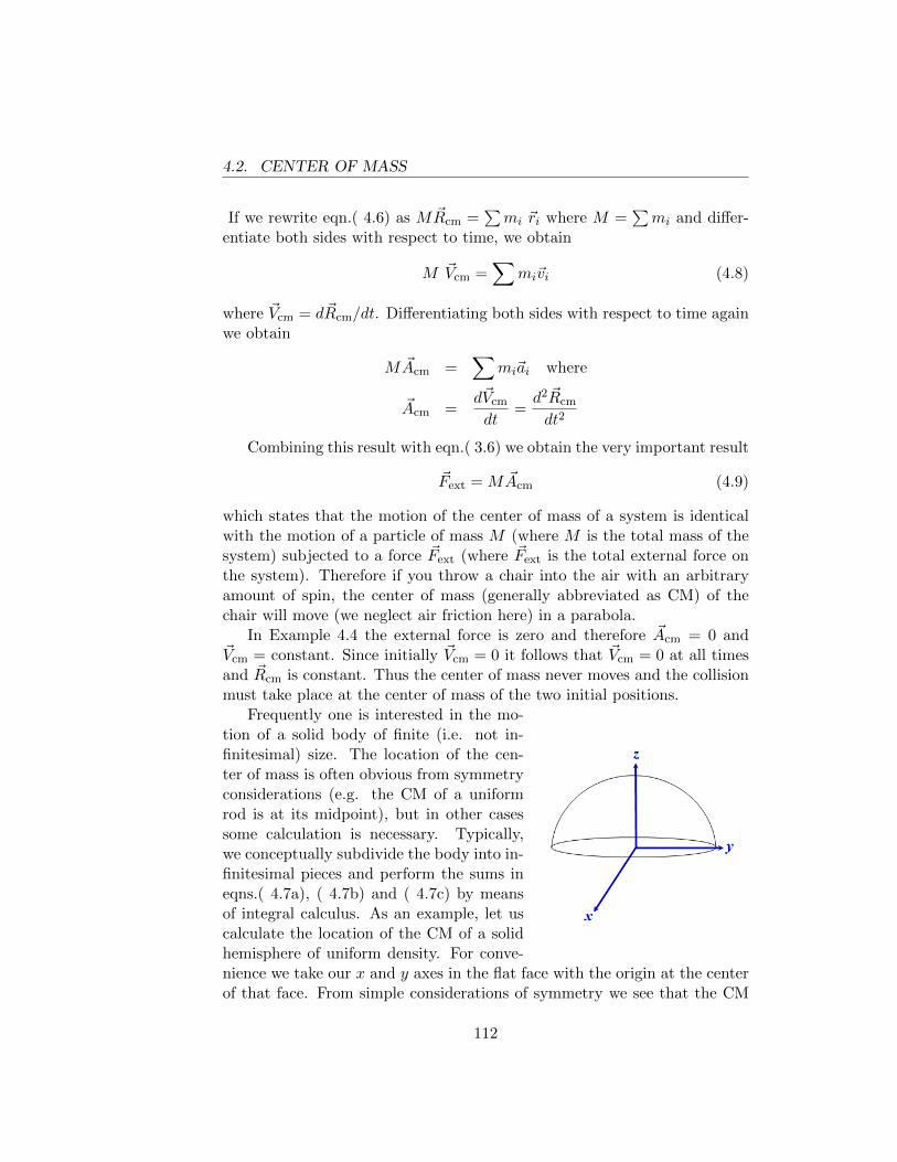
4.2. CENTER OF MASS
If we rewrite eqn.( 4.6) as M ~Rcm =∑mi ~ri where M =
∑mi and differ-
entiate both sides with respect to time, we obtain
M ~Vcm =∑
mi~vi (4.8)
where ~Vcm = d~Rcm/dt. Differentiating both sides with respect to time againwe obtain
M ~Acm =∑
mi~ai where
~Acm =d~Vcm
dt=d2 ~Rcm
dt2
Combining this result with eqn.( 3.6) we obtain the very important result
~Fext = M ~Acm (4.9)
which states that the motion of the center of mass of a system is identicalwith the motion of a particle of mass M (where M is the total mass of thesystem) subjected to a force ~Fext (where ~Fext is the total external force onthe system). Therefore if you throw a chair into the air with an arbitraryamount of spin, the center of mass (generally abbreviated as CM) of thechair will move (we neglect air friction here) in a parabola.
In Example 4.4 the external force is zero and therefore ~Acm = 0 and~Vcm = constant. Since initially ~Vcm = 0 it follows that ~Vcm = 0 at all timesand ~Rcm is constant. Thus the center of mass never moves and the collisionmust take place at the center of mass of the two initial positions.
Frequently one is interested in the mo-tion of a solid body of finite (i.e. not in-finitesimal) size. The location of the cen-ter of mass is often obvious from symmetryconsiderations (e.g. the CM of a uniformrod is at its midpoint), but in other casessome calculation is necessary. Typically,we conceptually subdivide the body into in-finitesimal pieces and perform the sums ineqns.( 4.7a), ( 4.7b) and ( 4.7c) by meansof integral calculus. As an example, let uscalculate the location of the CM of a solidhemisphere of uniform density. For conve-nience we take our x and y axes in the flat face with the origin at the centerof that face. From simple considerations of symmetry we see that the CM
112
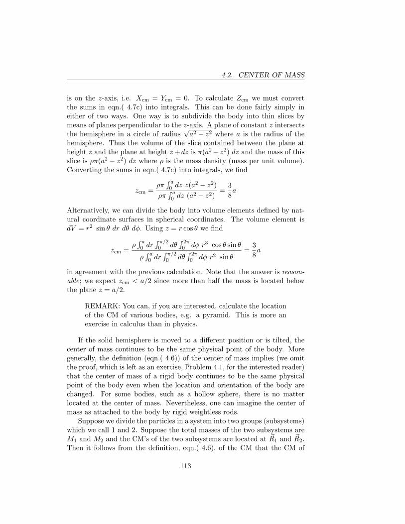
4.2. CENTER OF MASS
is on the z-axis, i.e. Xcm = Ycm = 0. To calculate Zcm we must convertthe sums in eqn.( 4.7c) into integrals. This can be done fairly simply ineither of two ways. One way is to subdivide the body into thin slices bymeans of planes perpendicular to the z-axis. A plane of constant z intersectsthe hemisphere in a circle of radius
√a2 − z2 where a is the radius of the
hemisphere. Thus the volume of the slice contained between the plane atheight z and the plane at height z+dz is π(a2− z2) dz and the mass of thisslice is ρπ(a2 − z2) dz where ρ is the mass density (mass per unit volume).Converting the sums in eqn.( 4.7c) into integrals, we find
zcm =ρπ∫ a
0 dz z(a2 − z2)
ρπ∫ a
0 dz (a2 − z2)=
3
8a
Alternatively, we can divide the body into volume elements defined by nat-ural coordinate surfaces in spherical coordinates. The volume element isdV = r2 sin θ dr dθ dφ. Using z = r cos θ we find
zcm =ρ∫ a
0 dr∫ π/2
0 dθ∫ 2π
0 dφ r3 cos θ sin θ
ρ∫ a
0 dr∫ π/2
0 dθ∫ 2π
0 dφ r2 sin θ=
3
8a
in agreement with the previous calculation. Note that the answer is reason-able; we expect zcm < a/2 since more than half the mass is located belowthe plane z = a/2.
REMARK: You can, if you are interested, calculate the locationof the CM of various bodies, e.g. a pyramid. This is more anexercise in calculus than in physics.
If the solid hemisphere is moved to a different position or is tilted, thecenter of mass continues to be the same physical point of the body. Moregenerally, the definition (eqn.( 4.6)) of the center of mass implies (we omitthe proof, which is left as an exercise, Problem 4.1, for the interested reader)that the center of mass of a rigid body continues to be the same physicalpoint of the body even when the location and orientation of the body arechanged. For some bodies, such as a hollow sphere, there is no matterlocated at the center of mass. Nevertheless, one can imagine the center ofmass as attached to the body by rigid weightless rods.
Suppose we divide the particles in a system into two groups (subsystems)which we call 1 and 2. Suppose the total masses of the two subsystems areM1 and M2 and the CM’s of the two subsystems are located at ~R1 and ~R2.Then it follows from the definition, eqn.( 4.6), of the CM that the CM of
113
4.2. CENTER OF MASS
the entire system is just the CM of two point masses: M1 located at ~R1
and M2 located at ~R2. Thus if two rods are welded together, the CM ofthe composite is just the CM of two masses located at the midpoints of therods.
Eqn.( 4.9) is of important practical interest when applied to a piece ofrotating machinery such as a flywheel. If the flywheel rotates around a fixedaxis, any physical point of the flywheel moves in a circle. Suppose the CMof the flywheel is not on the axis; then the CM moves in a circle and has anacceleration of magnitude v2/R directed toward the center, where v is thespeed of the CM and R is the distance of the CM from the center. If theflywheel makes n revolutions per second (n is called the frequency), thenv = 2π Rn and v2/R = 4π2n2R. If the mass of the flywheel is M , eqn.(4.9) states that an external force of magnitude 4π2n2RM is being applied tothe flywheel. This force is exerted by the bearings and is directed radiallyinward, along the instantaneous direction from the CM to the axis. Theflywheel exerts an equal and opposite force on the bearings, which wearsout the bearings or causes the bearings to vibrate, or both. For example,if the flywheel has a mass of 145 kg and is rotating 6000 times per minute(n = 100) and if the CM is 3.175 millimeters (1/8 of an inch) from theaxis, then the magnitude of this rapidly rotating force is 182,000 newtons or40,800 pounds or more than 20 tons. In order to make R = 0 one attaches apoint mass to the wheel, choosing the magnitude and location of the pointmass in such a way as to put the CM on the axis. This procedure is calledstatically balancing the wheel.
ADDENDUM FOR CAR OWNERS
Even after an object has been statically balanced, it may still exert fluctuat-ing forces on the bearings. Consider, for example, the system (see Fig. 4.2)
Figure 4.2: A dumbbell on an axle.
114
4.3. TIME-AVERAGED FORCE
consisting of an axle AB and a dumbbell welded to the axle. The weld isat the CM of the dumbbell, but the angle θ between the dumbbell and theaxle is not 90◦. The dumbbell and axle rotate about the direction AB, theaxle being supported by bearings at A and B. Since the CM is on the axisit is not accelerating and therefore the bearings exert no net force (exceptfor a constant upward force equal to the weight of the dumbbell and axle).However, at any instant the bearings at A and B exert equal and oppositefluctuating forces on the axle, canceling the “tendency” of the dumbbell toalign itself prependicular to the axis of rotation. These fluctuating forcesare eliminated by dynamic balancing , the theory of which is discussed inmost intermediate texts on mechanics.
4.3 Time-Averaged Force
In many situations the force on an object varies rapidly with time and thequantity of physical interest is the time-averaged force (for brevity we callit the average force). For example, as the molecules of a gas collide witha wall, each molecule exerts a force on the wall for a very short time; anymacroscopic apparatus which we use to measure the force exerted by themolecules on the wall will have a response time which is long compared tothe duration of a collision or the time between collisions. Thus the apparatuswill measure only the time-averaged force.
Suppose f(t) is some function of the time t. We define the time averageof f(t) by the equation
favg =1
t2 − t1
∫ t2
t1
f(t) dt. (4.10)
The average thus defined depends on t1 and t2, but in most cases of interestfavg does not depend on t1 and t2 provided that the length of the averaginginterval t2− t1 is not too small. For example, Fig. 4.3 is a graph of the forceexerted on the wall of a container by molecules colliding with the wall. Ifthe averaging interval includes many collisions then favg does not depend onthe length of the averaging interval. Note that the definition of favg impliesthat the area under the horizontal line is equal to the area under the actualfluctuating graph of force-versus-time.
If ~F (t) is a vector which varies with time, the time average of ~F issimilarly defined, i.e.
~Favg =1
t2 − t1
∫ t2
t1
~F (t) dt. (4.11)
115
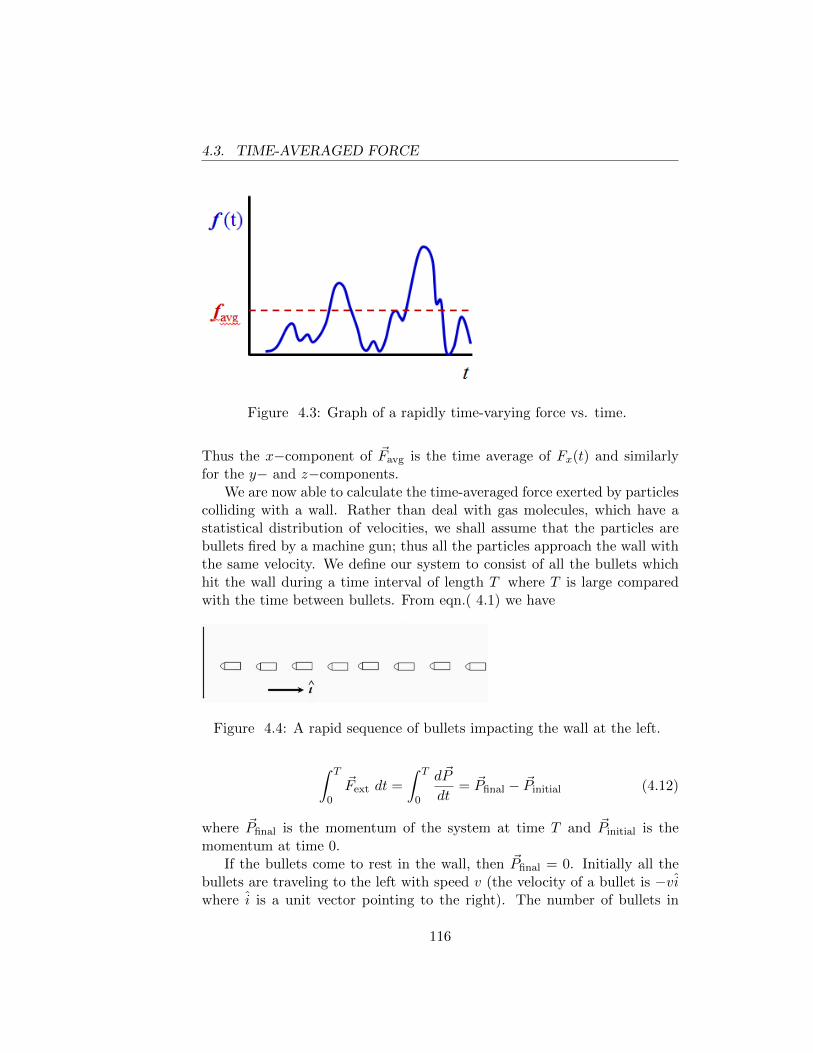
4.3. TIME-AVERAGED FORCE
Figure 4.3: Graph of a rapidly time-varying force vs. time.
Thus the x−component of ~Favg is the time average of Fx(t) and similarlyfor the y− and z−components.
We are now able to calculate the time-averaged force exerted by particlescolliding with a wall. Rather than deal with gas molecules, which have astatistical distribution of velocities, we shall assume that the particles arebullets fired by a machine gun; thus all the particles approach the wall withthe same velocity. We define our system to consist of all the bullets whichhit the wall during a time interval of length T where T is large comparedwith the time between bullets. From eqn.( 4.1) we have
Figure 4.4: A rapid sequence of bullets impacting the wall at the left.
∫ T
0
~Fext dt =
∫ T
0
d~P
dt= ~Pfinal − ~Pinitial (4.12)
where ~Pfinal is the momentum of the system at time T and ~Pinitial is themomentum at time 0.
If the bullets come to rest in the wall, then ~Pfinal = 0. Initially all thebullets are traveling to the left with speed v (the velocity of a bullet is −viwhere i is a unit vector pointing to the right). The number of bullets in
116
4.3. TIME-AVERAGED FORCE
our system is nT where n is the number of bullets hitting the wall per unittime. Thus we find ~Pinitial = −nTmvi, where m is the mass of a bullet. Theonly external force on our system is exerted by the wall. Using eqn.( 4.11)we find ~Favg = nmvi. This is the average force exerted by the wall on thebullets; the average force exerted by the bullets on the wall is −nmvi. If,instead of coming to rest in the wall, the bullets were to bounce off the wallwith velocity vi, then we would have ~Pfinal = nTmvi and the force on thewall would be double the previous value.
The example below is slightly advanced but will impress or alienate yourfriends if you discuss this at a party.
Example 4.5 : Sand in an hourglass.
An hourglass is placed on a scale. When all the sand is in the bottom ofthe hourglass, the scale reading is W (i.e. the weight of the hourglass plusall the sand is W ). What will the scale read while sand is falling throughthe hourglass? For definiteness we assume that a constant mass of sand perunit time (which we call ρ) falls through the hourglass and that all grainsof sand fall the same distance d (i.e. we ignore the piling-up of sand).
This question can be answered either by applying the general theoremeqn.( 4.9) to the system consisting of the hourglass and the sand, or byexamining in detail what is happening in the hourglass. Both methods areinstructive.
Let the z-axis point vertically upward and let us take z = 0 at the bottomof the hourglass. The height of the CM of the system (hourglass + sand) isdetermined by the equation
M Zcm =∑
mi zi
where M is the total mass of the system. At any instant of time the sumon the right can be decomposed into four pieces:
(I). the contribution from the sand in the upper chamber
(II). the contribution from the sand in the lower chamber
(III). the contribution from the sand which is falling
(IV). the contribution from the hourglass itself.
117
4.3. TIME-AVERAGED FORCE
I is equal to m(t)d where m(t) is the mass of sand in the upper chamberat time t. II vanishes because z = 0 at the bottom. III is constant intime because a photograph of the falling stream of sand looks the same atall times. And IV is obviously constant in time. Thus we have MZcm =m(t)d+constant. Differentiating both sides with respect to time and notingthat dm/dt = −ρ we obtain M dZcm/dt = −ρd and M d2Zcm/dt
2 = 0 sinceρ is assumed to be constant. It follows from eqn.( 4.9) that the net externalforce on the system is zero. But the external force is −Mg k + F k, where−Mg k is the gravitational force and F k is the force exerted by the scale.Thus we find F = Mg = W ; the scale reading is the same whether or notsand is falling. (Actually there is a brief transient effect at the beginningand the end since the picture of the falling sand is changing.)
Some people will argue that F should be less than Mg because the scaledoes not feel the weight of the sand which is freely falling. However, there isanother effect: the impact of the falling sand on the bottom, which increasesF . The preceding analysis of the center of mass motion, which completelybypasses the necessity of discussing these effects, also implies that the twoeffects must exactly cancel. We can see this in detail. If t is the timerequired for a grain of sand to fall a distance d, then the weight of the sandin free fall is ρ gt. The machine-gun calculation preceding this exampletells us that the impact of the falling sand creates an extra force ρ v on thescale, where v is the speed of a sand grain just before it hits the bottom(and ρ is indentical with nm in the machine-gun calculation). Since v = gt,the impact force exactly cancels the weight reduction, as expected. (Indeed,there is a transient decrease in the scale reading before the first grain of sandhits the bottom and a transient increase while the last grains are falling.)
Example 4.6 : Transporting pigeons in a truck.
A large tractor-trailer truck stops at an intersection; a pedestrian observesthat the driver jumps out of the cab, bangs furiously on the side of the trailerwith a two-by-four, and jumps back into the cab. In response to a queryfrom the pedestrian, the driver shouts ”The safe load limit for the tires is60,000 lbs. The rig weighs 40,000 lbs empty and I’ve got 40,000 lbs of livepigeons inside. So I’ve got to keep half the pigeons in the air.”
Will this scheme work?Let our system be the truck plus all its contents. If ~Favg is the time-
averaged force on the system, averaged over the time interval from t = 0
118
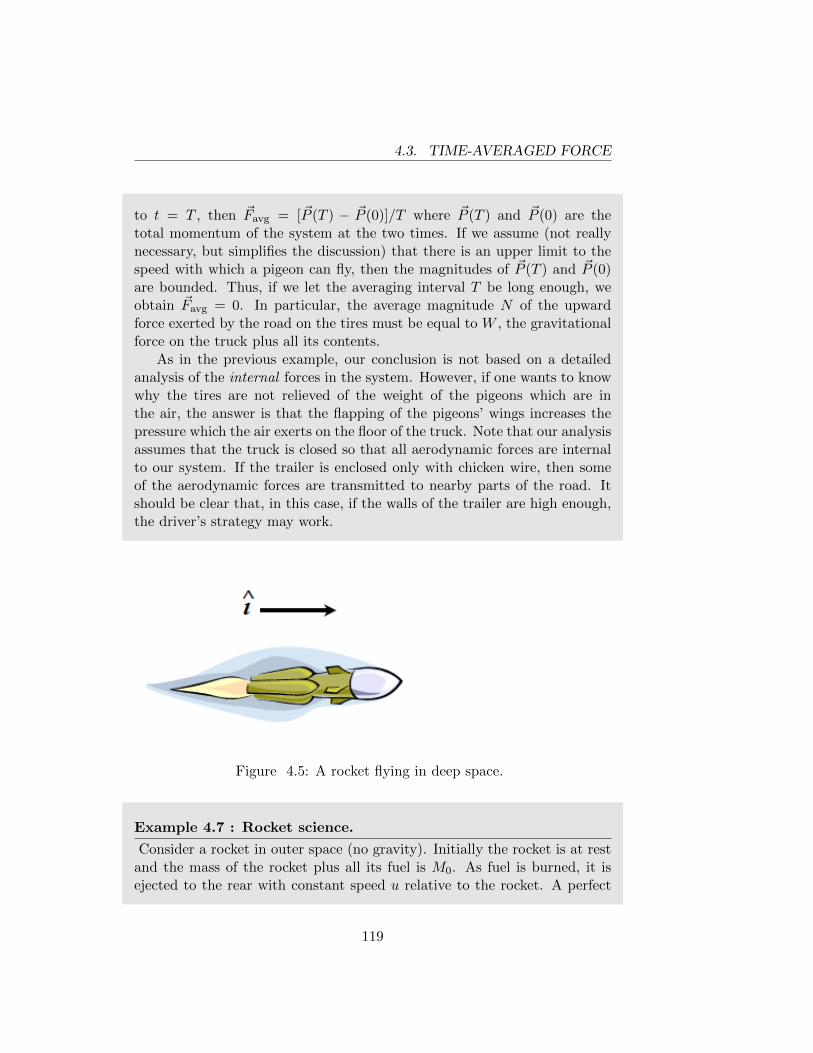
4.3. TIME-AVERAGED FORCE
to t = T , then ~Favg = [~P (T ) − ~P (0)]/T where ~P (T ) and ~P (0) are thetotal momentum of the system at the two times. If we assume (not reallynecessary, but simplifies the discussion) that there is an upper limit to thespeed with which a pigeon can fly, then the magnitudes of ~P (T ) and ~P (0)are bounded. Thus, if we let the averaging interval T be long enough, weobtain ~Favg = 0. In particular, the average magnitude N of the upwardforce exerted by the road on the tires must be equal to W , the gravitationalforce on the truck plus all its contents.
As in the previous example, our conclusion is not based on a detailedanalysis of the internal forces in the system. However, if one wants to knowwhy the tires are not relieved of the weight of the pigeons which are inthe air, the answer is that the flapping of the pigeons’ wings increases thepressure which the air exerts on the floor of the truck. Note that our analysisassumes that the truck is closed so that all aerodynamic forces are internalto our system. If the trailer is enclosed only with chicken wire, then someof the aerodynamic forces are transmitted to nearby parts of the road. Itshould be clear that, in this case, if the walls of the trailer are high enough,the driver’s strategy may work.
Figure 4.5: A rocket flying in deep space.
Example 4.7 : Rocket science.
Consider a rocket in outer space (no gravity). Initially the rocket is at restand the mass of the rocket plus all its fuel is M0. As fuel is burned, it isejected to the rear with constant speed u relative to the rocket. A perfect
119
4.3. TIME-AVERAGED FORCE
analogy is that of a woman, armed with a machine gun, sitting on a sledon smooth ice. As she fires the gun to the rear the recoil accelerates thesled. What is the velocity of the rocket at the instant when the mass of therocket plus the remaining fuel is M? (This relation does not depend on anyassumptions about the rate of burning, which is not necessarily constant. Ifgravity is included, then the burning program is important.)
We take as our system the rocket plus all the fuel on board at any giveninstant. Let the mass of the system be M , and let the velocity of the rocketat this instant be v i, where i is a unit vector pointing in the direction ofmotion of the rocket. We look at the same system (i.e. the same collectionof particles) at a slightly later instant. At this time the mass of the rocketplus on-board fuel is M+dM (note that dM is a negative quantity) and thevelocity of the rocket is (v + dv)i. Some of the particles of our system areno longer aboard the rocket; in fact, a mass −dM of fuel has been ejectedfrom the rocket and has velocity (v − u)i relative to an inertial observer.The forces exerted on the combustion chamber by the burning fuel, and thereactions to those forces, are all internal forces in our system. Thus thereare no external forces on the system and the total momentum of the systemat the initial instant must be equal to the total momentum at the slightlylater instant. Hence we find
Mv i = (M + dM)(v + dv) i− dM(v − u) i. (4.13)
Since the two instants can be as close in time as we wish, the second orderinfinitesimal term dM dv can be neglected in comparison with the termsproportional to dM or dv. (In fact, we already neglected second orderinfinitesimals in the second term of the above equation since the ejectedparticles can have a range of velocities from (v − u) i to (v + dv − u) i.)Canceling out the unit vector i, we obtain M dv + u dM = 0. Rewritingthis as
dM
M+dv
u= 0
we find d(lnM + v/u) = 0 which implies lnM + v/u = constant.If the initial velocity (at the instant when M = M0) is zero, then the
constant has the value lnM0 and we find v = u ln(M0/M). If the initialvelocity is v0 we get what is called the ideal rocket equation
v = v0 + u ln
(M0
M
). (4.14)
120
4.3. TIME-AVERAGED FORCE
From an engineering point of view it is instructive to write this equationin the form M0/M = exp[(v − v0)/u]. Usually one wants to put a certainmass M1 (called the payload) into an orbit which requires that v − v0 havea certain value w. In this case one must start with a mass M0, whereM0/M1 = exp(w/u). Suppose two fuels exist, the second having a value ofu twice as large as the first. Then if M0/M1 = 100 for the first fuel, we willhave M0/M1 = 10 for the second fuel.
121
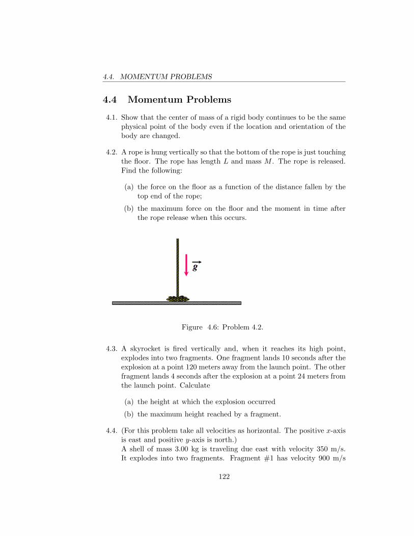
4.4. MOMENTUM PROBLEMS
4.4 Momentum Problems
4.1. Show that the center of mass of a rigid body continues to be the samephysical point of the body even if the location and orientation of thebody are changed.
4.2. A rope is hung vertically so that the bottom of the rope is just touchingthe floor. The rope has length L and mass M . The rope is released.Find the following:
(a) the force on the floor as a function of the distance fallen by thetop end of the rope;
(b) the maximum force on the floor and the moment in time afterthe rope release when this occurs.
Figure 4.6: Problem 4.2.
4.3. A skyrocket is fired vertically and, when it reaches its high point,explodes into two fragments. One fragment lands 10 seconds after theexplosion at a point 120 meters away from the launch point. The otherfragment lands 4 seconds after the explosion at a point 24 meters fromthe launch point. Calculate
(a) the height at which the explosion occurred
(b) the maximum height reached by a fragment.
4.4. (For this problem take all velocities as horizontal. The positive x-axisis east and positive y-axis is north.)A shell of mass 3.00 kg is traveling due east with velocity 350 m/s.It explodes into two fragments. Fragment #1 has velocity 900 m/s
122
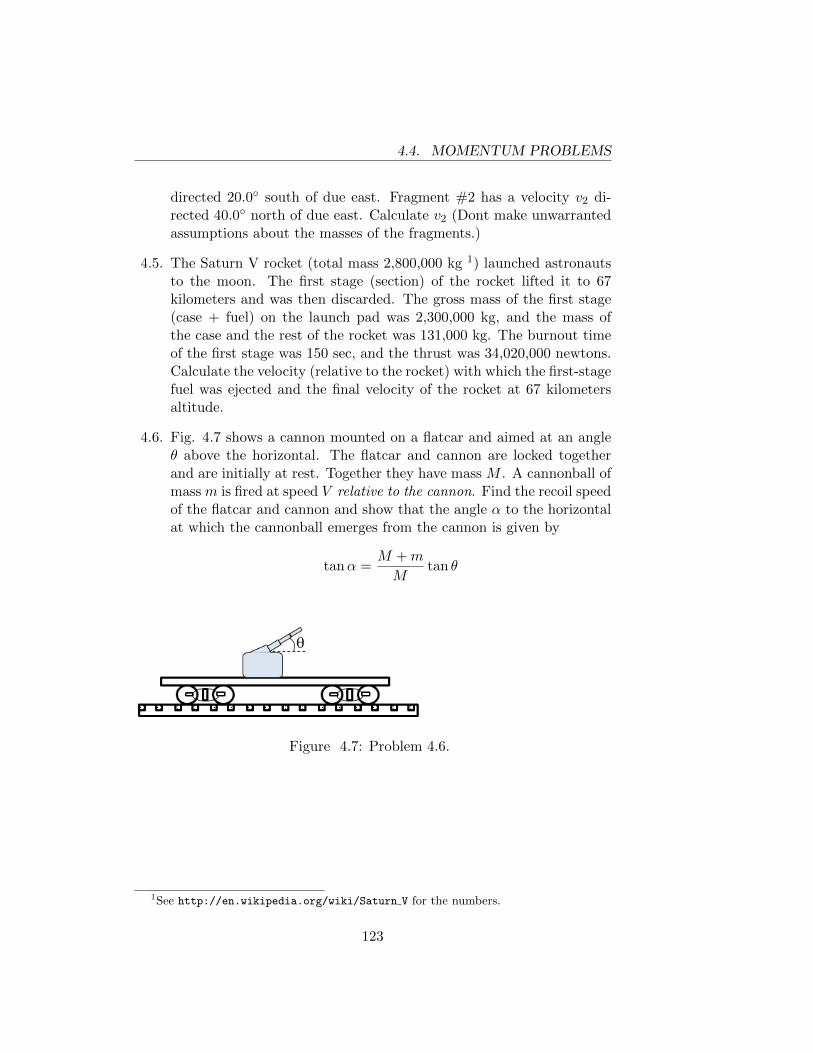
4.4. MOMENTUM PROBLEMS
directed 20.0◦ south of due east. Fragment #2 has a velocity v2 di-rected 40.0◦ north of due east. Calculate v2 (Dont make unwarrantedassumptions about the masses of the fragments.)
4.5. The Saturn V rocket (total mass 2,800,000 kg 1) launched astronautsto the moon. The first stage (section) of the rocket lifted it to 67kilometers and was then discarded. The gross mass of the first stage(case + fuel) on the launch pad was 2,300,000 kg, and the mass ofthe case and the rest of the rocket was 131,000 kg. The burnout timeof the first stage was 150 sec, and the thrust was 34,020,000 newtons.Calculate the velocity (relative to the rocket) with which the first-stagefuel was ejected and the final velocity of the rocket at 67 kilometersaltitude.
4.6. Fig. 4.7 shows a cannon mounted on a flatcar and aimed at an angleθ above the horizontal. The flatcar and cannon are locked togetherand are initially at rest. Together they have mass M . A cannonball ofmass m is fired at speed V relative to the cannon. Find the recoil speedof the flatcar and cannon and show that the angle α to the horizontalat which the cannonball emerges from the cannon is given by
tanα =M +m
Mtan θ
Figure 4.7: Problem 4.6.
1See http://en.wikipedia.org/wiki/Saturn V for the numbers.
123
4.4. MOMENTUM PROBLEMS
124
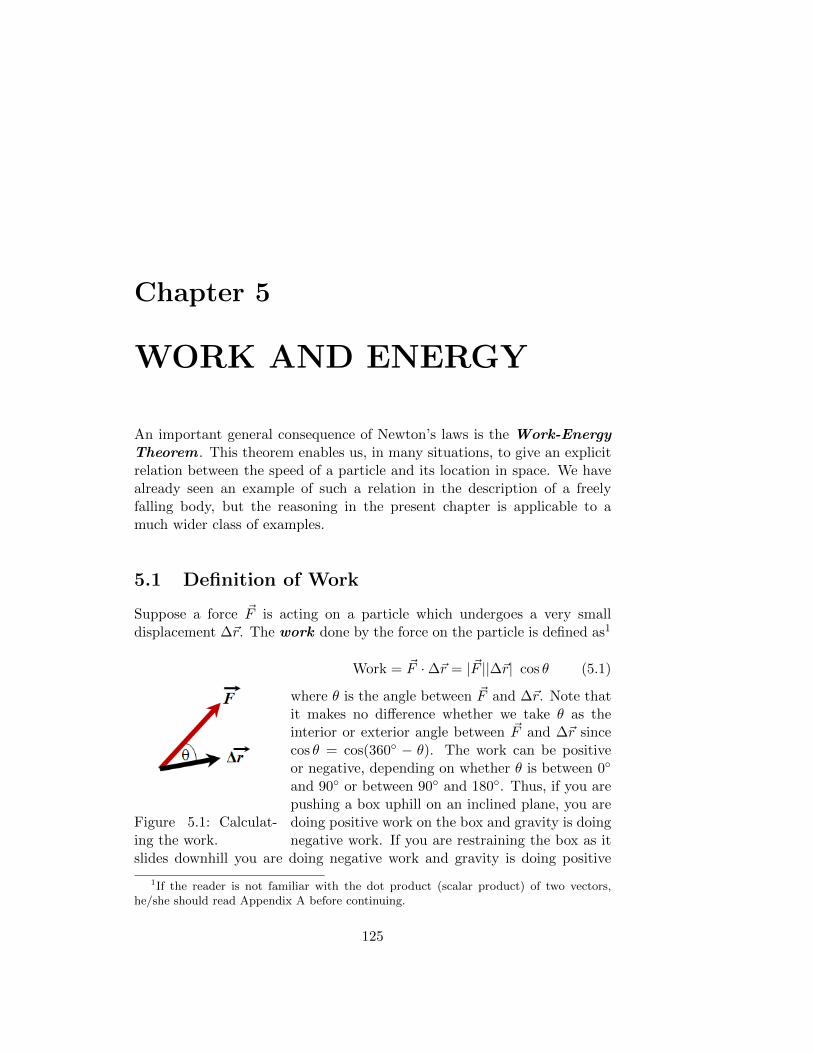
Chapter 5
WORK AND ENERGY
An important general consequence of Newton’s laws is the Work-EnergyTheorem . This theorem enables us, in many situations, to give an explicitrelation between the speed of a particle and its location in space. We havealready seen an example of such a relation in the description of a freelyfalling body, but the reasoning in the present chapter is applicable to amuch wider class of examples.
5.1 Definition of Work
Suppose a force ~F is acting on a particle which undergoes a very smalldisplacement ∆~r. The work done by the force on the particle is defined as1
Figure 5.1: Calculat-ing the work.
Work = ~F ·∆~r = |~F ||∆~r| cos θ (5.1)
where θ is the angle between ~F and ∆~r. Note thatit makes no difference whether we take θ as theinterior or exterior angle between ~F and ∆~r sincecos θ = cos(360◦ − θ). The work can be positiveor negative, depending on whether θ is between 0◦
and 90◦ or between 90◦ and 180◦. Thus, if you arepushing a box uphill on an inclined plane, you aredoing positive work on the box and gravity is doingnegative work. If you are restraining the box as it
slides downhill you are doing negative work and gravity is doing positive
1If the reader is not familiar with the dot product (scalar product) of two vectors,he/she should read Appendix A before continuing.
125
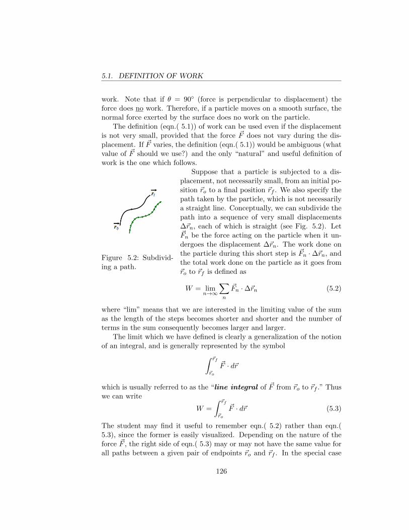
5.1. DEFINITION OF WORK
work. Note that if θ = 90◦ (force is perpendicular to displacement) theforce does no work. Therefore, if a particle moves on a smooth surface, thenormal force exerted by the surface does no work on the particle.
The definition (eqn.( 5.1)) of work can be used even if the displacementis not very small, provided that the force ~F does not vary during the dis-placement. If ~F varies, the definition (eqn.( 5.1)) would be ambiguous (whatvalue of ~F should we use?) and the only “natural” and useful definition ofwork is the one which follows.
Figure 5.2: Subdivid-ing a path.
Suppose that a particle is subjected to a dis-placement, not necessarily small, from an initial po-sition ~ro to a final position ~rf . We also specify thepath taken by the particle, which is not necessarilya straight line. Conceptually, we can subdivide thepath into a sequence of very small displacements∆~rn, each of which is straight (see Fig. 5.2). Let~Fn be the force acting on the particle when it un-dergoes the displacement ∆~rn. The work done onthe particle during this short step is ~Fn ·∆~rn, andthe total work done on the particle as it goes from~ro to ~rf is defined as
W = limn→∞
∑n
~Fn ·∆~rn (5.2)
where “lim” means that we are interested in the limiting value of the sumas the length of the steps becomes shorter and shorter and the number ofterms in the sum consequently becomes larger and larger.
The limit which we have defined is clearly a generalization of the notionof an integral, and is generally represented by the symbol∫ ~rf
~ro
~F · d~r
which is usually referred to as the “line integral of ~F from ~ro to ~rf .” Thuswe can write
W =
∫ ~rf
~ro
~F · d~r (5.3)
The student may find it useful to remember eqn.( 5.2) rather than eqn.(5.3), since the former is easily visualized. Depending on the nature of theforce ~F , the right side of eqn.( 5.3) may or may not have the same value forall paths between a given pair of endpoints ~ro and ~rf . In the special case
126
5.2. THE WORK-ENERGY THEOREM
where ~F has the same value at all points on the path we have (using thedistributive property of the dot product)
W = limn→∞
∑n
~Fn ·∆~rn = ~F · (~rf − ~ro) (5.4)
Example 5.1 : Work done by gravity.
Calculate the work done by gravity on a particle which moves from an initialposition ~ro to a final position ~rf . It is assumed that ~ro and ~rf are closeenough to the earth’s surface, and to each other, so that the gravitationalforce is constant, i.e. ~Fgrav = −mg k.
We can write ~r0 = x0 i + y0 j + z0 k and a similar expression for ~rf .
Using eqn.( 5.4) and k · i = 0, k · j = 0, k · k = 1 we find
Wgrav = mg (z0 − zf ). (5.5)
Note that the work done by gravity depends only on the initial and finalpositions and does not depend on what path the particle traversed betweenthose positions. This is true even when we take account of the variation ofthe magnitude and the direction of the gravitational force when the particlemoves through large distances. (The work done by gravity is the same forall paths between two given points, but is not in general given by eqn.( 5.5)).The signs with which z0 and zf enter eqn.( 5.5) are easily remembered bynoting that gravity does positive work on a particle which moves downward(force is parallel to displacement) and negative work on a particle whichmoves upward.
5.2 The Work-Energy Theorem
Let us consider a particle of mass m which at one instant of time t0 is at aposition ~r0 and has velocity ~v0, and at a later instant tf is at a position ~rfand has velocity ~vf . Let W be the total work done on the particle as it goesfrom ~r0 to ~rf . The Work-Energy Theorem asserts:
W =1
2mv2
f −1
2mv2
0 (5.6)
The quantity 12mv2 is called the kinetic energy of the particle; thus the
work-energy theorem can be stated in words as:
127
5.2. THE WORK-ENERGY THEOREM
The work done on a particle during any period of time is equalto the change2 in its kinetic energy.
To prove this theorem we start with Newton’s second law ~F = m~a andtake the dot product of both sides with the instantaneous velocity vector ~v,obtaining
~F · ~v = m~a · ~v (5.7)
Using d/dt( ~A · ~B) = ~A · d ~B/dt+ ~B · d ~A/dt (see Appendix A) we find
d
dt(~v · ~v) = 2~v · d~v
dt= 2~v · ~a
Thus
m~a · ~v =d
dt( 12m~v · ~v) =
d
dt
(12mv2
).
If we multiply both sides of eqn.( 5.7) by a very short time interval ∆t, weobtain
~F · ~v∆t =d
dt
(12mv2
)∆t. (5.8)
Since ~v∆t = ∆~r where ∆~r is the displacement which the particle undergoesduring the time interval ∆t, the left side of eqn.( 5.8) is the work ∆W doneon the particle during the time interval ∆t. The right side of eqn.( 5.8) isjust the change in the quantity 1
2mv2 during the time interval ∆t. Thus,
the work done on the particle during any short time interval is equal tothe change in its kinetic energy during this time interval. Subdividing theperiod from t0 to tf into many short time intervals, we see that the totalwork done on the particle during this period is equal to the final kineticenergy minus the initial kinetic energy, which proves eqn.( 5.6).
Application of the work-energy theorem to a freely falling particle yields
1
2mv2
f −1
2mv2
0 = mg(z0 − zf ). (5.9)
This result follows immediately from our work in Chapter 1 (recall that vxand vy are constant during free fall, so only vz is changing), but now we canshow that eqn.( 5.9) is also true in many situations where the particle is notfreely falling. Consider, for example, a particle moving under the influence ofgravity on a smooth surface of arbitrary shape. In this case, both the magni-tude and direction of the particle’s acceleration will usually vary with time;thus the analysis of motion with constant acceleration in Chapter 1 is not ap-plicable.
2The change in a quantity is defined as the final value of the quantity minus the initialvalue of the quantity.
128
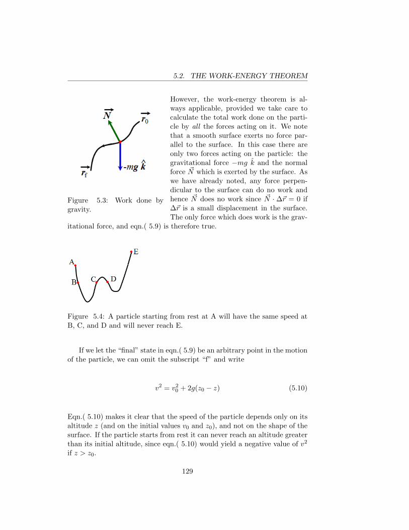
5.2. THE WORK-ENERGY THEOREM
Figure 5.3: Work done bygravity.
However, the work-energy theorem is al-ways applicable, provided we take care tocalculate the total work done on the parti-cle by all the forces acting on it. We notethat a smooth surface exerts no force par-allel to the surface. In this case there areonly two forces acting on the particle: thegravitational force −mg k and the normalforce ~N which is exerted by the surface. Aswe have already noted, any force perpen-dicular to the surface can do no work andhence ~N does no work since ~N · ∆~r = 0 if∆~r is a small displacement in the surface.The only force which does work is the grav-
itational force, and eqn.( 5.9) is therefore true.
Figure 5.4: A particle starting from rest at A will have the same speed atB, C, and D and will never reach E.
If we let the “final” state in eqn.( 5.9) be an arbitrary point in the motionof the particle, we can omit the subscript “f” and write
v2 = v20 + 2g(z0 − z) (5.10)
Eqn.( 5.10) makes it clear that the speed of the particle depends only on itsaltitude z (and on the initial values v0 and z0), and not on the shape of thesurface. If the particle starts from rest it can never reach an altitude greaterthan its initial altitude, since eqn.( 5.10) would yield a negative value of v2
if z > z0.
129
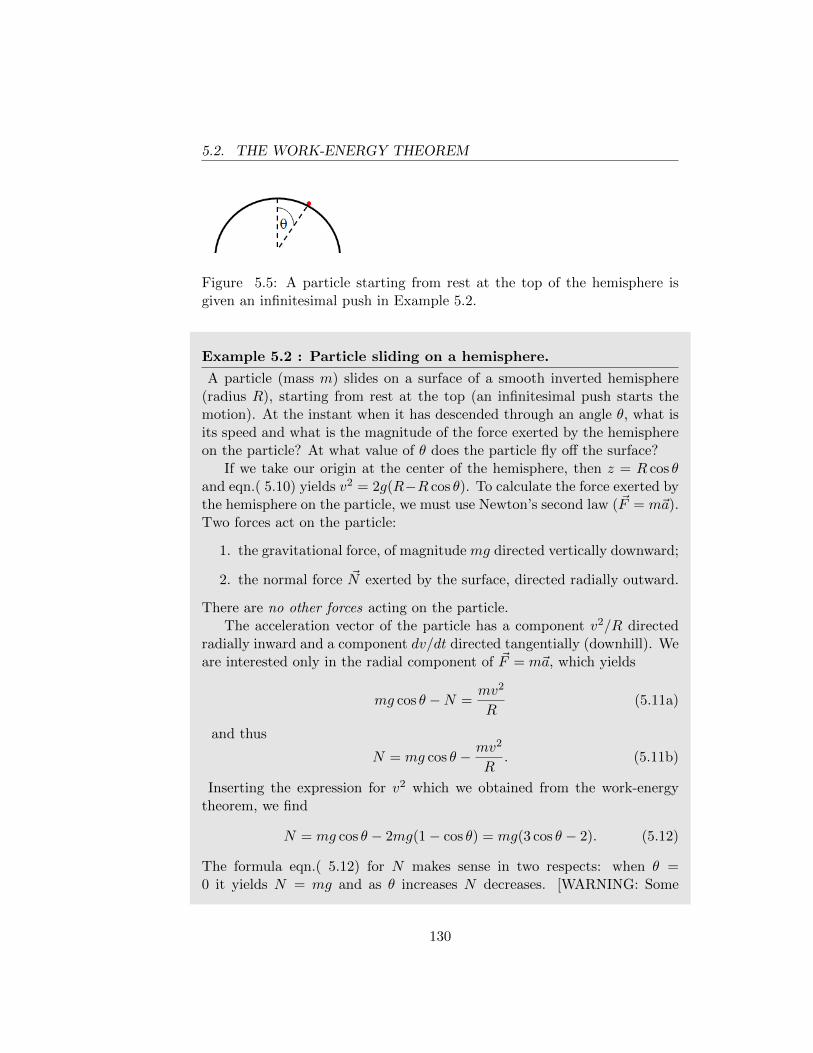
5.2. THE WORK-ENERGY THEOREM
Figure 5.5: A particle starting from rest at the top of the hemisphere isgiven an infinitesimal push in Example 5.2.
Example 5.2 : Particle sliding on a hemisphere.
A particle (mass m) slides on a surface of a smooth inverted hemisphere(radius R), starting from rest at the top (an infinitesimal push starts themotion). At the instant when it has descended through an angle θ, what isits speed and what is the magnitude of the force exerted by the hemisphereon the particle? At what value of θ does the particle fly off the surface?
If we take our origin at the center of the hemisphere, then z = R cos θand eqn.( 5.10) yields v2 = 2g(R−R cos θ). To calculate the force exerted bythe hemisphere on the particle, we must use Newton’s second law (~F = m~a).Two forces act on the particle:
1. the gravitational force, of magnitude mg directed vertically downward;
2. the normal force ~N exerted by the surface, directed radially outward.
There are no other forces acting on the particle.The acceleration vector of the particle has a component v2/R directed
radially inward and a component dv/dt directed tangentially (downhill). Weare interested only in the radial component of ~F = m~a, which yields
mg cos θ −N =mv2
R(5.11a)
and thus
N = mg cos θ − mv2
R. (5.11b)
Inserting the expression for v2 which we obtained from the work-energytheorem, we find
N = mg cos θ − 2mg(1− cos θ) = mg(3 cos θ − 2). (5.12)
The formula eqn.( 5.12) for N makes sense in two respects: when θ =0 it yields N = mg and as θ increases N decreases. [WARNING: Some
130
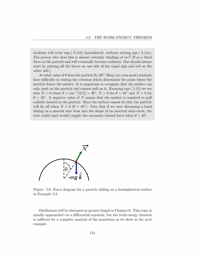
5.2. THE WORK-ENERGY THEOREM
students will write eqn.( 5.11b) immediately, without writing eqn.( 5.11a).The person who does this is almost certainly thinking of mv2/R as a thirdforce on the particle and will eventually become confused. One should alwaysstart by putting all the forces on one side of the equal sign and m~a on theother side.]
At what value of θ does the particle fly off? Many (or even most) studentshave difficulty in stating the criterion which determines the point where theparticle leaves the surface. It is important to recognize that the surface canonly push on the particle and cannot pull on it. Examing eqn.( 5.12) we seethat N = 0 when θ = cos−1(2/3) = 48◦, N > 0 for θ < 48◦ and N < 0 forθ > 48◦. A negative value of N means that the surface is required to pullradially inward on the particle. Since the surface cannot do this, the particlewill fly off when N = 0 (θ = 48◦). Note that if we were discussing a beadsliding on a smooth wire bent into the shape of an inverted semi-circle, thewire could (and would) supply the necessary inward force when θ > 48◦.
Figure 5.6: Force diagram for a particle sliding on a hemispherical surfacein Example 5.2.
Oscillations will be discussed at greater length in Chapter 6. This topic isusually approached via a differential equation, but the work-energy theoremis sufficent for a complete analysis of the pendulum as we show in the nextexample.
131
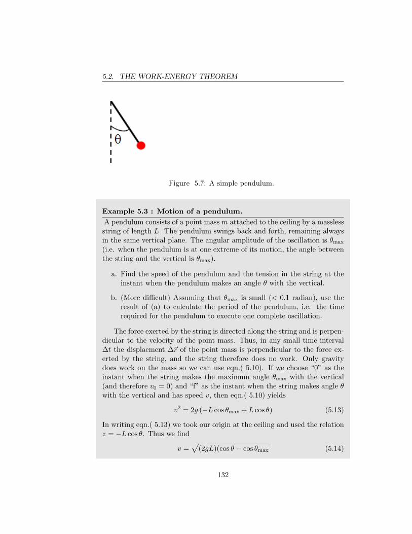
5.2. THE WORK-ENERGY THEOREM
Figure 5.7: A simple pendulum.
Example 5.3 : Motion of a pendulum.
A pendulum consists of a point mass m attached to the ceiling by a masslessstring of length L. The pendulum swings back and forth, remaining alwaysin the same vertical plane. The angular amplitude of the oscillation is θmax
(i.e. when the pendulum is at one extreme of its motion, the angle betweenthe string and the vertical is θmax).
a. Find the speed of the pendulum and the tension in the string at theinstant when the pendulum makes an angle θ with the vertical.
b. (More difficult) Assuming that θmax is small (< 0.1 radian), use theresult of (a) to calculate the period of the pendulum, i.e. the timerequired for the pendulum to execute one complete oscillation.
The force exerted by the string is directed along the string and is perpen-dicular to the velocity of the point mass. Thus, in any small time interval∆t the displacment ∆~r of the point mass is perpendicular to the force ex-erted by the string, and the string therefore does no work. Only gravitydoes work on the mass so we can use eqn.( 5.10). If we choose “0” as theinstant when the string makes the maximum angle θmax with the vertical(and therefore v0 = 0) and “f” as the instant when the string makes angle θwith the vertical and has speed v, then eqn.( 5.10) yields
v2 = 2g (−L cos θmax + L cos θ) (5.13)
In writing eqn.( 5.13) we took our origin at the ceiling and used the relationz = −L cos θ. Thus we find
v =√
(2gL)(cos θ − cos θmax (5.14)
132
5.2. THE WORK-ENERGY THEOREM
Eqn.( 5.14) gives the speed at any point in the pendulum’s motion. Duringa complete oscillation the pendulum passes through each point twice, oncegoing to the right and once going to the left.
The radial component of ~F = m~a yields
T −mg cos θ =mv2
L(5.15)
where T is the tension in the string. Solving for T and using eqn.( 5.13) wefind
T = mg(3 cos θ − 2 cos θmax)
This says that T is largest when θ = 0 and smallest when θ = θmax. Ifθmax is very small, then both cosines in the formula for T are close to 1 andT ' mg as expected.
We can use eqn.( 5.14) to calculate the period of the pendulum. As thestring’s angle with the vertical changes from θ to θ + dθ the mass travels adistance L dθ. The time required for the mass to travel this distance is
dt = Ldθ
v=
√L
2g
dθ√cos θ − cos θmax
(5.16)
The time required for the pendulum to go from its low point to one extremeof its oscillation is found by integrating the right side of eqn.( 5.16) withrespect to θ from θ = 0 to θ = θmax. This time is equal to one-fourth of theperiod τ . Thus we find
τ
4=
√L
2g
∫ θmax
0
dθ√cos θ − cos θmax
. (5.17)
The integral is not elementary (it is called an elliptic integral), but is easilyevaluated when θmax is sufficiently small. Using the Maclaurin series forcosine[oST10] (with θ measured in radians), cos θ = 1−θ2/2!+θ4/4!−... andomitting all terms after the first two, we obtain cos θ−cos θmax = 1
2(θ2
max−θ2)(with an error of less than one part in a thousand if θmax < 0.1 radian). Eqn.(5.17) then becomes
τ
4=
√L
g
∫ θmax
0
dθ√θ2
max − θ2. (5.18)
133
5.2. THE WORK-ENERGY THEOREM
If we make the change of variable x = θ/θmax the integral becomes∫ 1
0
dx√1− x2
At this stage, even before we evaluate the final integral, it is evident that theperiod does not depend on the angular amplitude θmax (provided θmax �1). This means that if there is some slight damping in the system (due toair resistance or friction in the suspension) which causes θmax to decreaseslowly, the period of the pendulum does not change as the angular amplitudedecreases. It is this property which allows the pendulum to be used as areliable clock.
To evaluate the final integral we make a further substitution x = sinφ.Using dx = cosφ dφ and
√1− x2 = cosφ, we find∫ 1
0
dx√1− x2
=
∫ π/2
0dφ =
π
2
and thus
τ = 2π
√L
g(5.19)
If the angular amplitude of the oscillation is not small, the period dependsslightly on the amplitude, increasing with increasing amplitude.
The preceding reasoning can be extended to give a complete descriptionof the motion of the pendulum, i.e. to give an explicit formular for the angleθ as a function of the time t. If we take t = 0 at the instant when thependulum passes through its low point, moving to the right, then the timet required for the pendulum to go from its low point out to an angle θ is
t = L
∫ θ
0
dθ′
v(θ′)
We have called the variable of integration θ′ in order to distinguish it fromθ, which is the upper limit of the integral.
Assuming again that θmax is very small, we obtain
t =
√L
g
∫ θ
0
dθ′√θ2
max − θ′ 2.
134
5.2. THE WORK-ENERGY THEOREM
With the change of variable θ′ = θmax sinφ we find
t =
√L
g
∫ sin−1 θ/θmax
0dφ =
√L
gsin−1
(θ
θmax
).
Solving for θ we obtain
θ = θmax sin
[√g
Lt
](5.20a)
which obviously describes an oscillatory motion. If we had taken t = 0 atthe instant when θ = θmax, then eqn.( 5.20a) would be replaced by
θ = θmax cos
[√g
Lt
](5.20b)
Figure 5.8: Sliding downhill and onto a flat field.
Example 5.4 : Sliding downhill.
A sled starts from rest, goes down a hill of length D1 and angle θ, andcontinues along a flat field, coming to rest at distance D2 from the bottomof the hill. By means of the work-energy theorem, derive an expression forthe coefficient of kinetic friction µk between the sled and the snow, in termsof D1, D2, and θ. [The corner is a short frictionless curve.] The hill and andthe field are covered with snow, but we assume that the effect of many sledshitting the corner has turned the corner into smooth ice. If the corner hasa non-zero coefficient of kinetic friction it is not correct to neglect the effect
135
5.3. POTENTIAL ENERGY
of the corner even if the corner is very short (see Problem 3.8).One way to solve this problem is to use ~F = m~a and the kinematic
equations of Chapter 1 (you should do this).The work-energy theorem permits a brief and direct solution. If we
choose “0” as the instant when the sled is at rest at the top of the hilland “f” as the instant when it comes finally to rest at the bottom, thenv0 = vf = 0 and therefore Wgrav +Wfric = 0 (where Wgrav and Wfric are thework done by gravity and friction, respectively). From eqn.( 5.5) we haveWgrav = mgD1 sin θ. On the the incline, the frictional force has magnitudeµkmg cos θ and is directed opposite to the motion of the sled; thus the workdone by friction as the sled descends the incline is −µkD1mg cos θ. Similarly,the work done by friction as the sled travels along the flat field is −µkmgD2.Thus we find
mgD1 sin θ − µkmgD1 cos θ − µkmgD2 = 0→
µk =D1 sin θ
D1 cos θ + D2.
5.3 Potential Energy
Whenever we find a situation in which the only force doing work on a par-ticle is the force of gravity (which, for the moment, is assumed constant inmagnitude and direction), eqn.( 5.9) is applicable. This equation can berewritten in the form
1
2mv2
0 +mgz0 =1
2mv2
f +mgzf .
Since 0 and f are arbitrary instants, we see that the quantity 12mv2 +mg z
has the same value at all times, i.e.
1
2mv2 +mg z = constant. (5.21)
Eqn.( 5.21) is identical in content with eqn.( 5.9), but we think about it ina somewhat different way. We have already given a name to the quantity12mv2, calling it the kinetic energy. Eqn.( 5.21) states that the sum of the
kinetic energy and the quantity mgz remains constant during the motion;
136
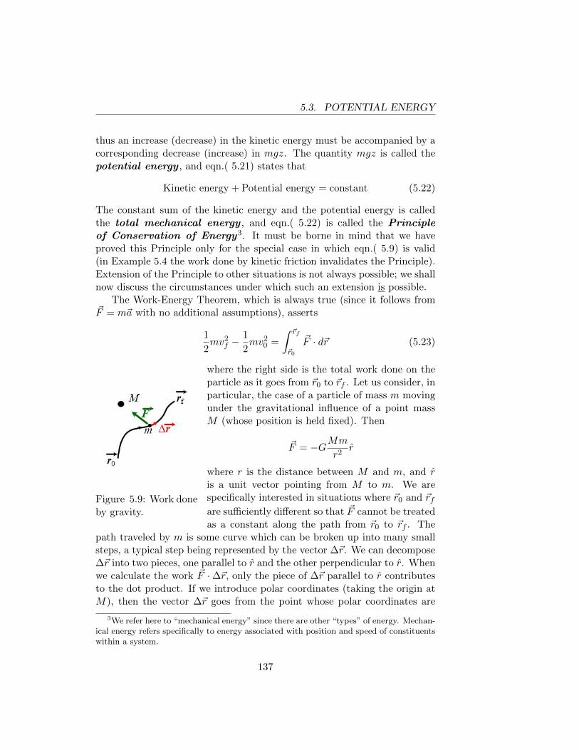
5.3. POTENTIAL ENERGY
thus an increase (decrease) in the kinetic energy must be accompanied by acorresponding decrease (increase) in mgz. The quantity mgz is called thepotential energy , and eqn.( 5.21) states that
Kinetic energy + Potential energy = constant (5.22)
The constant sum of the kinetic energy and the potential energy is calledthe total mechanical energy , and eqn.( 5.22) is called the Principleof Conservation of Energy3. It must be borne in mind that we haveproved this Principle only for the special case in which eqn.( 5.9) is valid(in Example 5.4 the work done by kinetic friction invalidates the Principle).Extension of the Principle to other situations is not always possible; we shallnow discuss the circumstances under which such an extension is possible.
The Work-Energy Theorem, which is always true (since it follows from~F = m~a with no additional assumptions), asserts
1
2mv2
f −1
2mv2
0 =
∫ ~rf
~r0
~F · d~r (5.23)
Figure 5.9: Work doneby gravity.
where the right side is the total work done on theparticle as it goes from ~r0 to ~rf . Let us consider, inparticular, the case of a particle of mass m movingunder the gravitational influence of a point massM (whose position is held fixed). Then
~F = −GMm
r2r
where r is the distance between M and m, and ris a unit vector pointing from M to m. We arespecifically interested in situations where ~r0 and ~rfare sufficiently different so that ~F cannot be treatedas a constant along the path from ~r0 to ~rf . The
path traveled by m is some curve which can be broken up into many smallsteps, a typical step being represented by the vector ∆~r. We can decompose∆~r into two pieces, one parallel to r and the other perpendicular to r. Whenwe calculate the work ~F ·∆~r, only the piece of ∆~r parallel to r contributesto the dot product. If we introduce polar coordinates (taking the origin atM), then the vector ∆~r goes from the point whose polar coordinates are
3We refer here to “mechanical energy” since there are other “types” of energy. Mechan-ical energy refers specifically to energy associated with position and speed of constituentswithin a system.
137
5.3. POTENTIAL ENERGY
(r, θ, φ) to the nearby point (r + ∆r, θ + ∆θ, φ + ∆φ). The piece of ∆~ralong the radial direction is (∆r)r, and thus we find
~F ·∆~r =
[−GMm
r2r
]· [(∆r)r] = −GMm
r2∆r
since r · r = 1.Letting ∆r → 0 and adding up the contributions from all the steps, we
find ∫ ~rf
~r0
~F · d~r = −∫ rf
r0
GMm
r2dr =
GMm
rf− GMm
r0. (5.24)
This calculation shows that the work done by gravity depends only on theend points of the path, and is therefore the same for all paths betweenthose end points (previously we showed this under the assumption that thegravitational force is constant). Inserting eqn.( 5.24) into eqn.( 5.23) we find
1
2mv2
f −1
2mv2
0 =GMm
rf− GMm
r0(5.25)
or equivalently1
2mv2 − GMm
r= constant. (5.26)
In this case we call −GMm/r the gravitational potential energy sincethe sum of this quantity and the kinetic energy remains constant.
In Chapter 3 we stated that (assuming the earth is spherical) the gravi-tational force exerted by the earth on an object outside the earth is identicalwith the gravitational force exerted by a point massMe (Me = mass of earth)located at the center of the earth. (We sketched how to prove this by inte-gral calculus, but did not give the proof.) Since g is the gravitational forceper unit mass acting on an object near the earth’s surface, it follows that
g =GMe
R2(5.27)
where R is the radius of the earth. Futhermore, if we are discussing themotion of a particle near the surface of the earth, we ought to be ableto show that the potential energy −GMem/r (where r is the distance of mfrom the center of the earth) is equivalent to the previously defined potentialenergy mgz. To see this we write r = z + R, where z is the altitude of theparticle above the earth’s surface. IF z � R we can use the binomialtheorem[oST10] to write
−GMem
z +R' −GMem
(1
R− z
R2
)= −GMem
R+mgz.
138
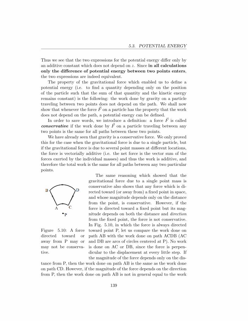
5.3. POTENTIAL ENERGY
Thus we see that the two expressions for the potential energy differ only byan additive constant which does not depend on z. Since in all calculationsonly the difference of potential energy between two points enters,the two expressions are indeed equivalent.
The property of the gravitational force which enabled us to define apotential energy (i.e. to find a quantity depending only on the positionof the particle such that the sum of that quantity and the kinetic energyremains constant) is the following: the work done by gravity on a particletraveling between two points does not depend on the path. We shall nowshow that whenever the force ~F on a particle has the property that the workdoes not depend on the path, a potential energy can be defined.
In order to save words, we introduce a definition: a force ~F is calledconservative if the work done by ~F on a particle traveling between anytwo points is the same for all paths between these two points.
We have already seen that gravity is a conservative force. We only provedthis for the case when the gravitational force is due to a single particle, butif the gravitational force is due to several point masses at different locations,the force is vectorially additive (i.e. the net force is the vector sum of theforces exerted by the individual masses) and thus the work is additive, andtherefore the total work is the same for all paths between any two particularpoints.
Figure 5.10: A forcedirected toward oraway from P may ormay not be conserva-tive.
The same reasoning which showed that thegravitational force due to a single point mass isconservative also shows that any force which is di-rected toward (or away from) a fixed point in space,and whose magnitude depends only on the distancefrom the point, is conservative. However, if theforce is directed toward a fixed point but its mag-nitude depends on both the distance and directionfrom the fixed point, the force is not conservative.In Fig. 5.10, in which the force is always directedtoward point P, let us compare the work done onpath AB with the work done on path ACDB (ACand DB are arcs of circles centered at P). No workis done on AC or DB, since the force is perpen-dicular to the displacement at every little step. Ifthe magnitude of the force depends only on the dis-
tance from P, then the work done on path AB is the same as the work doneon path CD. However, if the magnitude of the force depends on the directionfrom P, then the work done on path AB is not in general equal to the work
139
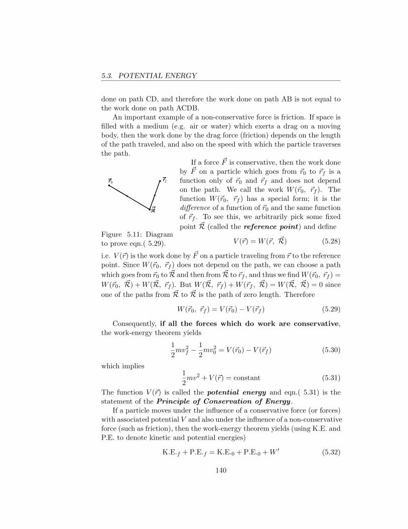
5.3. POTENTIAL ENERGY
done on path CD, and therefore the work done on path AB is not equal tothe work done on path ACDB.
An important example of a non-conservative force is friction. If space isfilled with a medium (e.g. air or water) which exerts a drag on a movingbody, then the work done by the drag force (friction) depends on the lengthof the path traveled, and also on the speed with which the particle traversesthe path.
Figure 5.11: Diagramto prove eqn.( 5.29).
If a force ~F is conservative, then the work doneby ~F on a particle which goes from ~r0 to ~rf is afunction only of ~r0 and ~rf and does not dependon the path. We call the work W (~r0, ~rf ). Thefunction W (~r0, ~rf ) has a special form; it is thedifference of a function of ~r0 and the same functionof ~rf . To see this, we arbitrarily pick some fixed
point ~R (called the reference point) and define
V (~r) = W (~r, ~R) (5.28)
i.e. V (~r) is the work done by ~F on a particle traveling from ~r to the referencepoint. Since W (~r0, ~rf ) does not depend on the path, we can choose a path
which goes from ~r0 to ~R and then from ~R to ~rf , and thus we findW (~r0, ~rf ) =
W (~r0, ~R) +W ( ~R, ~rf ). But W ( ~R, ~rf ) +W (~rf , ~R) = W ( ~R, ~R) = 0 since
one of the paths from ~R to ~R is the path of zero length. Therefore
W (~r0, ~rf ) = V (~r0)− V (~rf ) (5.29)
Consequently, if all the forces which do work are conservative,the work-energy theorem yields
1
2mv2
f −1
2mv2
0 = V (~r0)− V (~rf ) (5.30)
which implies1
2mv2 + V (~r) = constant (5.31)
The function V (~r) is called the potential energy and eqn.( 5.31) is thestatement of the Principle of Conservation of Energy .
If a particle moves under the influence of a conservative force (or forces)with associated potential V and also under the influence of a non-conservativeforce (such as friction), then the work-energy theorem yields (using K.E. andP.E. to denote kinetic and potential energies)
K.E.f + P.E.f = K.E.0 + P.E.0 +W ′ (5.32)
140
5.3. POTENTIAL ENERGY
where W ′ is the work done by the non-conservative forces as the particlemoves from ~r0 to ~rf . If the non-conservative force is a frictional drag directedopposite to the motion, then W ′ < 0.
The reference point ~R is arbitrary. A change in the reference point causesthe potential energy at all points to change by an additive constant (provethis!). Since eqn.( 5.30) involves the difference of the potential energies attwo points, an additive constant in V will not change anything. The def-inition eqn.( 5.28) implies V ( ~R) = 0. Thus, if we define the gravitationalpotential energy as V (~r) = −GMm/|~r|, we have chosen the reference point~R as a point infinitely far away from the mass M . If we choose the referencepoint as a point on the earth’s surface, then V (~r) = −GMm/|~r|+GMm/R.In this case the potential at points near the earth’s surface is mgz, in agree-ment with our earlier work.
Example 5.5 : The earth’s escape velocity.
With what speed must a projectile be fired from the earth’s surface in orderto escape to infinity? (Ignore air resistance, the effect of the earth’s rotation,and the effects of the sun and the moon.)
If ve is the speed of the projectile when it leaves the earth, and v∞ isthe speed of the projectile when it is infinitely far (i.e. its distance from theearth is a large multiple of the earth’s radius R), then eqn.( 5.31) implies
1
2mv2
e −GMem
R=
1
2mv2∞ (5.33)
We are interested in the minimum value of ve which will permit the projectileto reach infinity. Setting v∞ = 0, we find ve =
√2GMe/R =
√2gR. This
speed is called the escape velocity from the earth. Note that ve =√
2vo,where vo is the velocity of a satellite in a circular orbit with radius equalto the earth’s radius (see Chapter 3). Numerically, vo = 18, 000 mi/hr andve = 25, 000 mi/hr. Space scientists and science fiction writers sometimesdescribe low earth orbit as being “halfway to anywhere” or “halfway toinfinity”, since the kinetic energy of a projectile in low earth orbit is halfthe kinetic energy required to escape entirely from the earth’s gravitationalinfluence.
141
5.4. MORE GENERAL SIGNIFICANCE OF ENERGY (QUALITATIVEDISCUSSION)
5.4 More General Significance of Energy (Quali-tative Discussion)
The reader will probably have recognized that, as far as solving problemsis concerned, the Work-Energy Theorem is sufficient for our purposes inbeginning physics. The introduction of the concept of potential energy wasnot really necessary. Nevertheless, every text on mechanics introduces theconcept “potential energy” and encourages students to use the Principle ofConservation of Energy whenever possible; the student must keep in mind,however, that when non-conservative forces are present (the most commonbeing friction) mechanical energy is not conserved.
What is the reason for this emphasis on energy and Conservation ofEnergy, when the latter principle appears not always to be true? The answeris: if we look at things in sufficient detail (this may require a very powerfulmicroscope) we will find that energy is always conserved.
Consider, for example, a block which slides on a horizontal table andeventually comes to rest because of friction. Initially the block has kineticenergy, and finally it has none. The gravitational potential energy of theblock is the same in the initial and final states. Thus mechanical energy(as we have defined it) is not conserved, and the final mechanical energyminus the initial mechanical energy is equal to W ′, the work done by fric-tion. However, if we could examine the block with a sufficiently powerfulmicroscope we could see that the individual molecules in the block are not atrest, but jiggle around their equilibrium positions in a rather random fash-ion. Furthermore, we would see that the amount of molecular jiggling in thefinal state of the block is somewhat greater than the amount of molecularjiggling in the initial state. Macroscopically, we would find that the blockin its final state is slightly warmer than it was in the initial state. Similarly,the molecules of the table increase their jiggling when the block slides overthem, and the surface of the table becomes slightly warmer. Each jigglingmolecule has kinetic energy, and there is a significant amount of “invisible”kinetic energy in the form of molecular jiggling.
When we speak of “kinetic energy” in classical mechanics, we refer onlyto the visible kinetic energy of the block (i.e. 1
2MV 2 where M and V are the
mass and velocity of the block) and do not keep track of the “invisible” ki-netic energy. If we were to include the invisible kinetic energy in our accountbooks we would find that the total mechanical energy of the system (block +table) in the final state is equal to the total mechanical energy of the system(block + table) in the initial state. In short, the macroscopic kinetic energy
142
5.5. ELASTIC AND INELASTIC COLLISIONS
which the block loses is converted into increased kinetic energy of jiggling ofthe molecules in the block and in the table. From the macroscopic point ofview of classical mechanics energy can be lost, but from a microscopic pointof view some energy is merely being transformed into a less visible form.
For completeness we should note that “invisible” energy need not nec-essarily be kinetic energy, but can also be potential energy. For example,when a bullet comes to rest in a block of wood, not all the kinetic energy ofthe bullet is converted into kinetic energy of molecular jiggling. The woodhas an internal potential energy which depends on the arrangement of themolecules, which changes when the bullet enters the block. The kinetic en-ergy of the bullet is converted partly into energy of molecular jiggling andpartly into internal potential energy of the wood.
The proof of the fact that energy (appropriately defined) is always con-served falls outside the scope of Newtonian mechanics. Remarkably, New-tonian mechanics is able to make many predictions which do not dependon what is happening at the microscopic level; the accurate description ofmany of these phenomena requires quantum mechanics, which is radi-cally different from Newtonian mechanics. We stress again that within theframework of our (narrow, but useful) macroscopic definition of energy, theenergy of a system may or may not be conserved.
5.5 Elastic and Inelastic Collisions
We have already discussed a collision in which the two colliding objectsstick together. In this case the final velocity is determined by the Principleof Conservation of Momentum. In particular, let us consider a particle ofmass m1 and velocity ~v1 which collides with a particle of mass m2 whichis initially at rest. If the two particles stick together, the final velocity is~V = (m1/m1 +m2)~v1. The final kinetic energy is
1
2(m1 +m2)V 2 =
1
2
m21v
21
(m1 +m2).
Since the initial kinetic energy was 12m1v
21, we have
K.E.final
K.E.initial=
m1
m1 +m2.
Thus if m1 = m2 we find that half of the original kinetic energy is lost in thecollision. According to the discussion in the preceding section, the missing
143
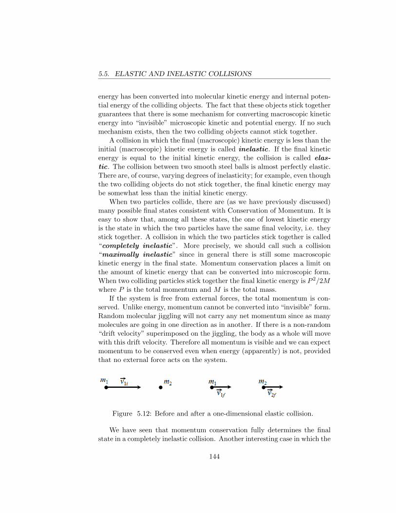
5.5. ELASTIC AND INELASTIC COLLISIONS
energy has been converted into molecular kinetic energy and internal poten-tial energy of the colliding objects. The fact that these objects stick togetherguarantees that there is some mechanism for converting macroscopic kineticenergy into “invisible” microscopic kinetic and potential energy. If no suchmechanism exists, then the two colliding objects cannot stick together.
A collision in which the final (macroscopic) kinetic energy is less than theinitial (macroscopic) kinetic energy is called inelastic. If the final kineticenergy is equal to the initial kinetic energy, the collision is called elas-tic. The collision between two smooth steel balls is almost perfectly elastic.There are, of course, varying degrees of inelasticity; for example, even thoughthe two colliding objects do not stick together, the final kinetic energy maybe somewhat less than the initial kinetic energy.
When two particles collide, there are (as we have previously discussed)many possible final states consistent with Conservation of Momentum. It iseasy to show that, among all these states, the one of lowest kinetic energyis the state in which the two particles have the same final velocity, i.e. theystick together. A collision in which the two particles stick together is called“completely inelastic”. More precisely, we should call such a collision“maximally inelastic” since in general there is still some macroscopickinetic energy in the final state. Momentum conservation places a limit onthe amount of kinetic energy that can be converted into microscopic form.When two colliding particles stick together the final kinetic energy is P 2/2Mwhere P is the total momentum and M is the total mass.
If the system is free from external forces, the total momentum is con-served. Unlike energy, momentum cannot be converted into “invisible” form.Random molecular jiggling will not carry any net momentum since as manymolecules are going in one direction as in another. If there is a non-random“drift velocity” superimposed on the jiggling, the body as a whole will movewith this drift velocity. Therefore all momentum is visible and we can expectmomentum to be conserved even when energy (apparently) is not, providedthat no external force acts on the system.
Figure 5.12: Before and after a one-dimensional elastic collision.
We have seen that momentum conservation fully determines the finalstate in a completely inelastic collision. Another interesting case in which the
144
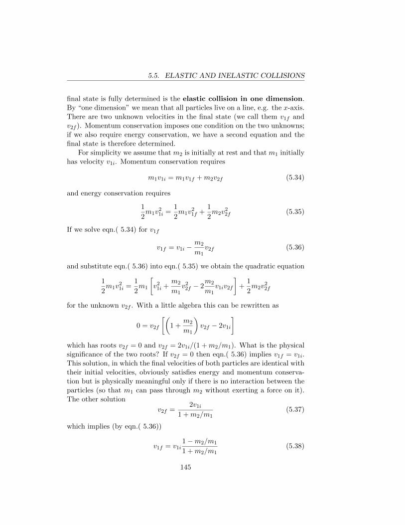
5.5. ELASTIC AND INELASTIC COLLISIONS
final state is fully determined is the elastic collision in one dimension.By “one dimension” we mean that all particles live on a line, e.g. the x-axis.There are two unknown velocities in the final state (we call them v1f andv2f ). Momentum conservation imposes one condition on the two unknowns;if we also require energy conservation, we have a second equation and thefinal state is therefore determined.
For simplicity we assume that m2 is initially at rest and that m1 initiallyhas velocity v1i. Momentum conservation requires
m1v1i = m1v1f +m2v2f (5.34)
and energy conservation requires
1
2m1v
21i =
1
2m1v
21f +
1
2m2v
22f (5.35)
If we solve eqn.( 5.34) for v1f
v1f = v1i −m2
m1v2f (5.36)
and substitute eqn.( 5.36) into eqn.( 5.35) we obtain the quadratic equation
1
2m1v
21i =
1
2m1
[v2
1i +m2
m1v2
2f − 2m2
m1v1iv2f
]+
1
2m2v
22f
for the unknown v2f . With a little algebra this can be rewritten as
0 = v2f
[(1 +
m2
m1
)v2f − 2v1i
]which has roots v2f = 0 and v2f = 2v1i/(1 +m2/m1). What is the physicalsignificance of the two roots? If v2f = 0 then eqn.( 5.36) implies v1f = v1i.This solution, in which the final velocities of both particles are identical withtheir initial velocities, obviously satisfies energy and momentum conserva-tion but is physically meaningful only if there is no interaction between theparticles (so that m1 can pass through m2 without exerting a force on it).The other solution
v2f =2v1i
1 +m2/m1(5.37)
which implies (by eqn.( 5.36))
v1f = v1i1−m2/m1
1 +m2/m1(5.38)
145
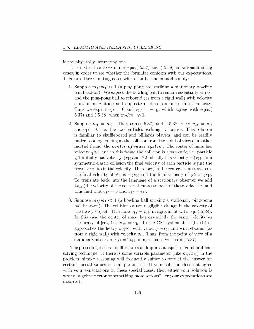
5.5. ELASTIC AND INELASTIC COLLISIONS
is the physically interesting one.It is instructive to examine eqns.( 5.37) and ( 5.38) in various limiting
cases, in order to see whether the formulae conform with our expectations.There are three limiting cases which can be understood simply:
1. Suppose m2/m1 � 1 (a ping-pong ball striking a stationary bowlingball head-on). We expect the bowling ball to remain essentially at restand the ping-pong ball to rebound (as from a rigid wall) with velocityequal in magnitude and opposite in direction to its initial velocity.Thus we expect v2f = 0 and v1f = −v1i, which agrees with eqns.(5.37) and ( 5.38) when m2/m1 � 1.
2. Suppose m1 = m2. Then eqns.( 5.37) and ( 5.38) yield v2f = v1i
and v1f = 0, i.e. the two particles exchange velocities. This solutionis familiar to shuffleboard and billiards players, and can be readilyunderstood by looking at the collision from the point of view of anotherinertial frame, the center-of-mass system . The center of mass hasvelocity 1
2v1i, and in this frame the collision is symmetric, i.e. particle
#1 initially has velocity 12v1i and #2 initially has velocity − 1
2v1i. In a
symmetric elastic collision the final velocity of each particle is just thenegative of its initial velocity. Therefore, in the center-of-mass system,the final velocity of #1 is − 1
2v1i and the final velocity of #2 is 1
2v1i.
To translate back into the language of a stationary observer we add12v1i (the velocity of the center of mass) to both of these velocities and
thus find that v1f = 0 and v2f = v1i.
3. Suppose m2/m1 � 1 (a bowling ball striking a stationary ping-pongball head-on). The collision causes negligible change in the velocity ofthe heavy object. Therefore v1f = v1i, in agreement with eqn.( 5.38).In this case the center of mass has essentially the same velocity asthe heavy object, i.e. vcm = v1i. In the CM system the light objectapproaches the heavy object with velocity −v1i and will rebound (asfrom a rigid wall) with velocity v1i. Thus, from the point of view of astationary observer, v2f = 2v1i, in agreement with eqn.( 5.37).
The preceding discussion illustrates an important aspect of good problem-solving technique. If there is some variable parameter (like m2/m1) in theproblem, simple reasoning will frequently suffice to predict the answer forcertain special values of that parameter. If your solution does not agreewith your expectations in these special cases, then either your solution iswrong (algebraic error or something more serious?) or your expectations areincorrect.
146
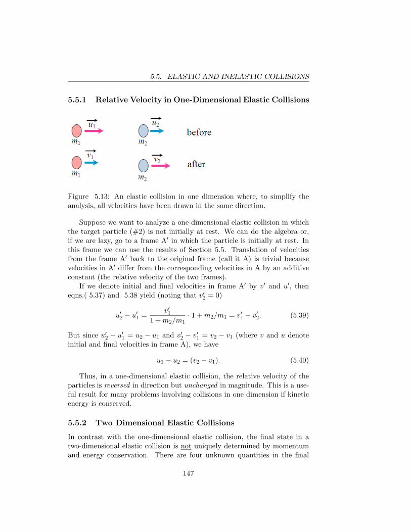
5.5. ELASTIC AND INELASTIC COLLISIONS
5.5.1 Relative Velocity in One-Dimensional Elastic Collisions
Figure 5.13: An elastic collision in one dimension where, to simplify theanalysis, all velocities have been drawn in the same direction.
Suppose we want to analyze a one-dimensional elastic collision in whichthe target particle (#2) is not initially at rest. We can do the algebra or,if we are lazy, go to a frame A′ in which the particle is initially at rest. Inthis frame we can use the results of Section 5.5. Translation of velocitiesfrom the frame A′ back to the original frame (call it A) is trivial becausevelocities in A′ differ from the corresponding velocities in A by an additiveconstant (the relative velocity of the two frames).
If we denote initial and final velocities in frame A′ by v′ and u′, theneqns.( 5.37) and 5.38 yield (noting that v′2 = 0)
u′2 − u′1 =v′1
1 +m2/m1· 1 +m2/m1 = v′1 − v′2. (5.39)
But since u′2 − u′1 = u2 − u1 and v′2 − v′1 = v2 − v1 (where v and u denoteinitial and final velocities in frame A), we have
u1 − u2 = (v2 − v1). (5.40)
Thus, in a one-dimensional elastic collision, the relative velocity of theparticles is reversed in direction but unchanged in magnitude. This is a use-ful result for many problems involving collisions in one dimension if kineticenergy is conserved.
5.5.2 Two Dimensional Elastic Collisions
In contrast with the one-dimensional elastic collision, the final state in atwo-dimensional elastic collision is not uniquely determined by momentumand energy conservation. There are four unknown quantities in the final
147
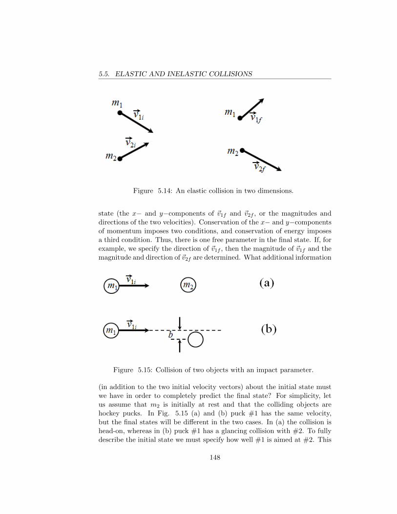
5.5. ELASTIC AND INELASTIC COLLISIONS
Figure 5.14: An elastic collision in two dimensions.
state (the x− and y−components of ~v1f and ~v2f , or the magnitudes anddirections of the two velocities). Conservation of the x− and y−componentsof momentum imposes two conditions, and conservation of energy imposesa third condition. Thus, there is one free parameter in the final state. If, forexample, we specify the direction of ~v1f , then the magnitude of ~v1f and themagnitude and direction of ~v2f are determined. What additional information
Figure 5.15: Collision of two objects with an impact parameter.
(in addition to the two initial velocity vectors) about the initial state mustwe have in order to completely predict the final state? For simplicity, letus assume that m2 is initially at rest and that the colliding objects arehockey pucks. In Fig. 5.15 (a) and (b) puck #1 has the same velocity,but the final states will be different in the two cases. In (a) the collision ishead-on, whereas in (b) puck #1 has a glancing collision with #2. To fullydescribe the initial state we must specify how well #1 is aimed at #2. This
148
5.6. POWER AND UNITS OF WORK
is usually done by the giving the value of the impact parameter b (seeFig. 5.15), the distance by which the center of #1 would miss the center of#2 if #1 were not deflected. The interested reader may find it instructiveto calculate ~v1f and ~v2f in terms of ~v1i and the impact parameter, but weomit the calculation here. The key point is that, if the surfaces of the pucksare smooth, the direction of ~v2f (i.e. the direction of the impulse given to#2) is along the line from the center of #1 to the center of #2 at the instantwhen the pucks touch. In one dimension everyone is a perfect marksman,i.e. the impact parameter is always zero.
5.6 Power and Units of Work
Work has the units of (force)× (distance). The unit of work in the Englishsystem is the foot-pound (ft-lb). In the mks system the unit of work isthe newton-meter, usually called the joule . The reader should verify that1 joule = .738 ft-lb.
In many situations one is interested in the rate at which work is done.For example, the horsepower rating of a motor measures the rate at whichit can do work; any motor can do an arbitrarily large amount of work if it isallowed to run for a sufficiently long time. Similarly, the wattage rating ofan electric bulb measures the amount of energy per unit time which mustbe supplied to the bulb to keep it operating. If the bulb is operated by aman-powered or steam-powered generator, the generator must do work at arate equal to the wattage.
The rate of work is called power ; power has the units of (work)/ (time)or (energy)/(time), since work and energy have the same units. In theEnglish system the unit of power is 1 ft-lb/sec. This unit has no othername, but 550 ft-lb/sec is called 1 horsepower . Thus a 1/2 horsepowermotor can do work at the rate of 275 foot-pounds per seconed. By attachingappropriate gears to the output shaft we can use the motor to lift a 25 lbweight at the rate of 11 ft/sec or a 50 lb weight at the rate of 5.5 ft/sec, etc.In the mks system the unit of power is 1 joule/sec, which is called 1 watt .Since 1 watt = .738 ft-lb/sec it follows that 1 horsepower = 746 watts = .746kilowatts. Since the watt and kilowatt have the units of (energy)/(time),the kilowatt-hour (kwh) can be used as a unit of energy; 1 kwh = (1000joules/sec)× (3600 sec) = 3.6× 10⁶ joules = 2.66× 106 ft-lb.4
4A kilowatt-hour, for which a consumer in Philadelphia pays 15 cents, is the energyrequired to lift an average automobile from the ground to the observation deck of theEmpire State Building.
149
5.6. POWER AND UNITS OF WORK
The energy content of food is measured in food calories. 1 food calorie= 4184 joules = 3085.96003 ft-lbs. The food calorie is equal to 1000 of thescientific unit calorie , the little calorie being the amount of energy requiredto raise the temperature of one gram of water by one degree centigrade. Theaverage American adult male takes in about 3000 calories per day (estimatesvary); his rate of energy consumption is (3000× 4184) joules/(24× 3600 sec)= 145 watts. Most of this energy is used to support biological processesand eventually appears as heat given off by the body. Thus it is feasiblefor universities, which are beset by high energy costs, to use students as themajor source of heat for auditoriums.
A mountaineer in good physical condition can climb (at low altitudes)at the rate of 300 vertical meters per hour for a few hours. If she/he has amass of 60 kg, the rate at which she/he does useful work (i.e. work whichappears as increased gravitational potential energy rather than as heat givenoff by the body) is (60 kg)× (9.8 m/s2)× (300 m) / 3600 sec = 49 watts= 0.066 hp. Thus, a 60-watt bulb is equivalent to the full-time effort of ahealthy human being. Some athletes can perform useful work at the rateof one horsepower for a very short time (for example, a football player whoweighs 184 lb might run up a flight of stairs at the rate of 3 vertical feet persecond). An excellent method of inducing a heart attack is to push hard onthe rear of a moving car. If you push with a force of 55 lb on a car movingwith a velocity of 10 ft/sec you are working at the rate of one horsepower.
If a force ~F is acting on an object which undergoes a small displacment∆~r during a small time interval ∆t, the work done by the force is ~F · ∆~rand the rate of work is ~F ·∆~r/∆t = ~F · ~v. If the object to which the forceis applied is a particle of mass m and if ~F is the total force acting on theparticle, then ~F = m d~v/dt and the instantaneous power delivered by ~F ism(d~v/dt) · ~v = d/dt( 1
2mv2).
Example 5.6 : Power to the particle.
A particle of mass 2 kg moves along the x-axis. Its position at time t isgiven by x = 4t+4t2− t3 where x is in meters and t is in seconds. Calculatethe instantaneous power being delivered to the particle at t = 1 and t = 2.
The velocity is ~v = (dx/dt) i = i(4 + 8t − 3t2) and the acceleration isd~v/dt = (8 − 6t) i. Evaluating m(d~v/dt) · ~v at t = 1 and t = 2 we find:instantaneous power = 36 watts when t = 1 and −64 watts when t = 2.The negative value at t = 2 results from the fact that at that instant theforce and the velocity have opposite directions.
150
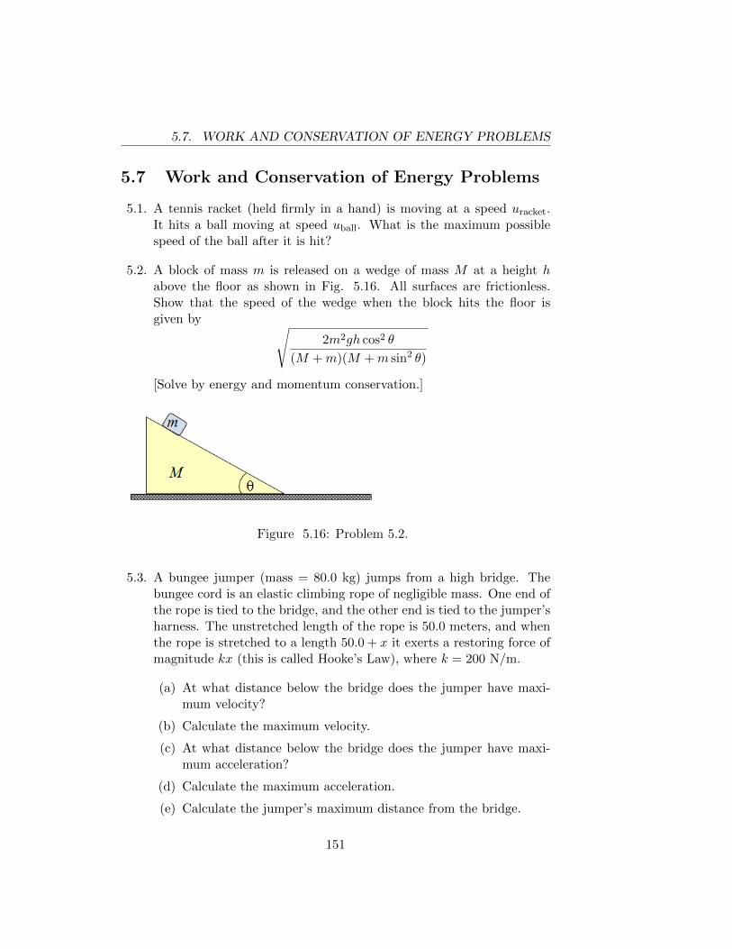
5.7. WORK AND CONSERVATION OF ENERGY PROBLEMS
5.7 Work and Conservation of Energy Problems
5.1. A tennis racket (held firmly in a hand) is moving at a speed uracket.It hits a ball moving at speed uball. What is the maximum possiblespeed of the ball after it is hit?
5.2. A block of mass m is released on a wedge of mass M at a height habove the floor as shown in Fig. 5.16. All surfaces are frictionless.Show that the speed of the wedge when the block hits the floor isgiven by √
2m2gh cos2 θ
(M +m)(M +m sin2 θ)
[Solve by energy and momentum conservation.]
Figure 5.16: Problem 5.2.
5.3. A bungee jumper (mass = 80.0 kg) jumps from a high bridge. Thebungee cord is an elastic climbing rope of negligible mass. One end ofthe rope is tied to the bridge, and the other end is tied to the jumper’sharness. The unstretched length of the rope is 50.0 meters, and whenthe rope is stretched to a length 50.0 + x it exerts a restoring force ofmagnitude kx (this is called Hooke’s Law), where k = 200 N/m.
(a) At what distance below the bridge does the jumper have maxi-mum velocity?
(b) Calculate the maximum velocity.
(c) At what distance below the bridge does the jumper have maxi-mum acceleration?
(d) Calculate the maximum acceleration.
(e) Calculate the jumper’s maximum distance from the bridge.
151
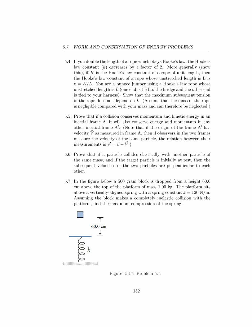
5.7. WORK AND CONSERVATION OF ENERGY PROBLEMS
5.4. If you double the length of a rope which obeys Hooke’s law, the Hooke’slaw constant (k) decreases by a factor of 2. More generally (showthis), if K is the Hooke’s law constant of a rope of unit length, thenthe Hooke’s law constant of a rope whose unstretched length is L isk = K/L. You are a bungee jumper using a Hooke’s law rope whoseunstretched length is L (one end is tied to the bridge and the other endis tied to your harness). Show that the maximum subsequent tensionin the rope does not depend on L. (Assume that the mass of the ropeis negligible compared with your mass and can therefore be neglected.)
5.5. Prove that if a collision conserves momentum and kinetic energy in aninertial frame A, it will also conserve energy and momentum in anyother inertial frame A′. (Note that if the origin of the frame A′ hasvelocity ~V as measured in frame A, then if observers in the two framesmeasure the velocity of the same particle, the relation between theirmeasurements is ~v′ = ~v − ~V .)
5.6. Prove that if a particle collides elastically with another particle ofthe same mass, and if the target particle is initially at rest, then thesubsequent velocities of the two particles are perpendicular to eachother.
5.7. In the figure below a 500 gram block is dropped from a height 60.0cm above the top of the platform of mass 1.00 kg. The platform sitsabove a vertically-aligned spring with a spring constant k = 120 N/m.Assuming the block makes a completely inelastic collision with theplatform, find the maximum compression of the spring.
Figure 5.17: Problem 5.7.
152
5.7. WORK AND CONSERVATION OF ENERGY PROBLEMS
5.8. Two planets, both of mass M , are separated by a distance D. Theirrelative velocity is negligible, and there is an inertial frame in whichboth planets are essentially at rest. The gravitational potential u(~r) isdefined as the gravitational potential energy of a particle of unit masswhen it is at the position ~r. In the presence of the two planets, locatedat ~R1 and ~R2, the potential is
u(~r) = − GM∣∣∣~R1 − ~r∣∣∣ − GM∣∣∣~R2 − ~r
∣∣∣ .This problem takes place far out in space. There are no other massiveobjects in the vicinity of the two planets.
(a) Draw a qualitatively correct graph of u as a function of positionalong the line between the two planets.
(b) There are space stations Alpha and Beta located on the line be-tween the planets. Both space stations are at rest with respect tothe planets. Alpha is at distance D/4 from planet #1 and Betais at distance D/3 from planet #2. A projectile of mass m isfired from station Alpha, with its velocity ~v pointing directly atplanet #2. What is the minimum speed v which will permit theprojectile to reach station Beta?
153
5.7. WORK AND CONSERVATION OF ENERGY PROBLEMS
154
Chapter 6
SIMPLE HARMONICMOTION
Oscillations are a common phenomenon in our experience. We have alreadydiscussed the motion of a pendulum (Chapter 5, Example 5.3). Anotherexample, which (we shall see) is mathematically identical with the small os-cillations of a pendulum, is the vertical oscillation of a mass suspended fromthe ceiling by a spring. A slightly more complicated example is the motion ofa rocking chair, and a considerably more complicated example is the motionof a violin string. The common feature of these examples is that initiallya system is somehow pushed away from its equilibrium configuration; how-ever, the forces which act on the system drive it back toward the equilibriumconfiguration. When the system reaches the equilibrium configuration it hasa finite velocity and therefore overshoots; once it is on the other side, theforces are again directed toward the equilibrium configuration to which iteventually returns, overshooting in the opposite direction and so on.
6.1 Hooke’s Law and the Differential Equation forSimple Harmonic Motion
The motion of a particle under the influence of a force whose magnitudeis proportional to the distance of the particle from its equilibrium posi-tion and whose direction is always toward the equilibrium position is calledsimple harmonic motion (SHM). Let us consider, for example, a parti-cle moving in one dimension on a smooth horizontal surface. A spring isattached to the particle and the other end of the spring is attached to a wall
155
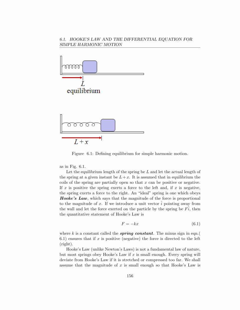
6.1. HOOKE’S LAW AND THE DIFFERENTIAL EQUATION FORSIMPLE HARMONIC MOTION
Figure 6.1: Defining equilibrium for simple harmonic motion.
as in Fig. 6.1.Let the equilibrium length of the spring be L and let the actual length of
the spring at a given instant be L+x. It is assumed that in equilibrium thecoils of the spring are partially open so that x can be positive or negative.If x is positive the spring exerts a force to the left and, if x is negative,the spring exerts a force to the right. An “ideal” spring is one which obeysHooke’s Law , which says that the magnitude of the force is proportionalto the magnitude of x. If we introduce a unit vector i pointing away fromthe wall and let the force exerted on the particle by the spring be F i, thenthe quantitative statement of Hooke’s Law is
F = −kx (6.1)
where k is a constant called the spring constant . The minus sign in eqn.(6.1) ensures that if x is positive (negative) the force is directed to the left(right).
Hooke’s Law (unlike Newton’s Laws) is not a fundamental law of nature,but most springs obey Hooke’s Law if x is small enough. Every spring willdeviate from Hooke’s Law if it is stretched or compressed too far. We shallassume that the magnitude of x is small enough so that Hooke’s Law is
156
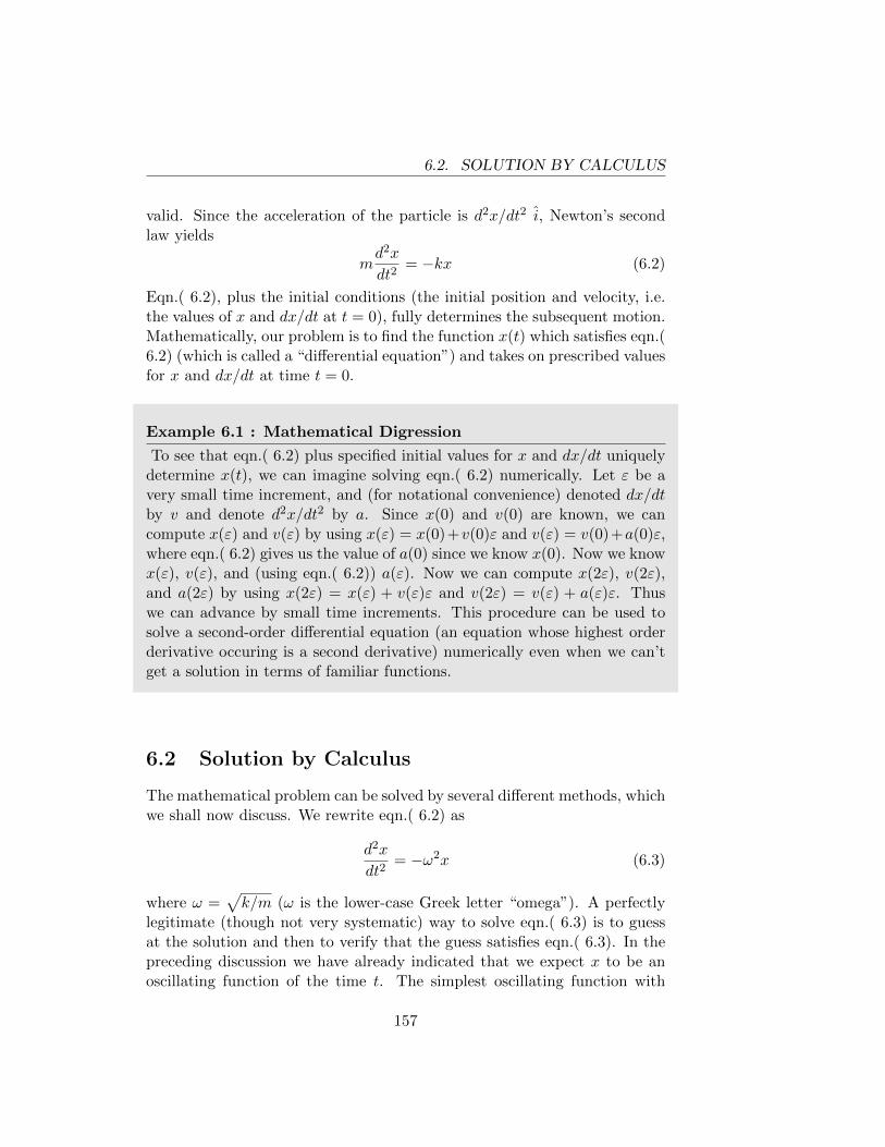
6.2. SOLUTION BY CALCULUS
valid. Since the acceleration of the particle is d2x/dt2 i, Newton’s secondlaw yields
md2x
dt2= −kx (6.2)
Eqn.( 6.2), plus the initial conditions (the initial position and velocity, i.e.the values of x and dx/dt at t = 0), fully determines the subsequent motion.Mathematically, our problem is to find the function x(t) which satisfies eqn.(6.2) (which is called a “differential equation”) and takes on prescribed valuesfor x and dx/dt at time t = 0.
Example 6.1 : Mathematical Digression
To see that eqn.( 6.2) plus specified initial values for x and dx/dt uniquelydetermine x(t), we can imagine solving eqn.( 6.2) numerically. Let ε be avery small time increment, and (for notational convenience) denoted dx/dtby v and denote d2x/dt2 by a. Since x(0) and v(0) are known, we cancompute x(ε) and v(ε) by using x(ε) = x(0)+v(0)ε and v(ε) = v(0)+a(0)ε,where eqn.( 6.2) gives us the value of a(0) since we know x(0). Now we knowx(ε), v(ε), and (using eqn.( 6.2)) a(ε). Now we can compute x(2ε), v(2ε),and a(2ε) by using x(2ε) = x(ε) + v(ε)ε and v(2ε) = v(ε) + a(ε)ε. Thuswe can advance by small time increments. This procedure can be used tosolve a second-order differential equation (an equation whose highest orderderivative occuring is a second derivative) numerically even when we can’tget a solution in terms of familiar functions.
6.2 Solution by Calculus
The mathematical problem can be solved by several different methods, whichwe shall now discuss. We rewrite eqn.( 6.2) as
d2x
dt2= −ω2x (6.3)
where ω =√k/m (ω is the lower-case Greek letter “omega”). A perfectly
legitimate (though not very systematic) way to solve eqn.( 6.3) is to guessat the solution and then to verify that the guess satisfies eqn.( 6.3). In thepreceding discussion we have already indicated that we expect x to be anoscillating function of the time t. The simplest oscillating function with
157
6.2. SOLUTION BY CALCULUS
which we are familiar is sin t. Since d/dt(sin t) = cos t and d/dt(cos t) =− sin t, we have d2/dt2(sin t) = − sin t. Thus we see that sin t almostsatisfies eqn.( 6.3), up to the factor ω2. This is easily fixed by trying thefunction sinωt. Since d/dt(sinωt) = ω cosωt and d/dt(cosωt) = −ω sin(ωt)we have d2/dt2(sinωt) = −ω2 sinωt. Thus we see that the function x(t) =sinωt satisfies eqn.( 6.3). Similarly we see that x(t) = cosωt also satisfieseqn.( 6.3). This is not surprising since the graph of cosωt is exactly thesame as the graph of sinωt provided that the time origin is shifted, i.e.cosωt = sinω(t+ π/2ω). Finally,
x(t) = A sinωt+B cosωt (6.4)
satisfies eqn.( 6.3) and is, in fact, its most general solution.By choosing A and B appropriately we can arrange for x and dx/dt to
take on any prescribed values at t = 0. Suppose that we want x to have thevalue x0 and dx/dt to have the value v0 at t = 0 (physically we can let x0
and v0 have any desired values if we start the motion “by hand” and thenlet go). Letting t = 0 in eqn.( 6.4) we find B = x0. Differentiating eqn.(6.4) with respect to time, we obtain
dx
dt= ωA cosωt− ωB sinωt (6.5)
Thus, the values of A and B which fit the initial conditions are B = x0 andA = v0/ω, and we obtain
x(t) =v0
ωsinωt+ x0 cosωt (6.6)
Note that if x0 = 0 the displacement x(t) is proportional to sinωt, and ifv0 = 0 the displacement is proportional to cosωt (we have already seen thisin our discussion of the small oscillations of a pendulum (Example 5.3)).Even when x0 6= 0 and v0 6= 0 we can, by an appropriate shift of the timeorigin, exhibit x(t) as a pure sine function or a pure cosine function. To dothis we write eqn.( 6.4) as
x(t) =√A2 +B2
[A√
A2 +B2sinωt+
B√A2 +B2
cosωt
](6.7)
where it is understood that we always choose the positive square root. Forgiven values of A and B there is a unique angle δ in the range −π < δ ≤ πsuch that
cos δ =B√
A2 +B2(6.8)
158
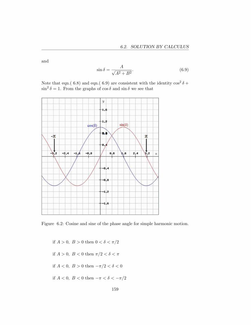
6.2. SOLUTION BY CALCULUS
and
sin δ =A√
A2 +B2. (6.9)
Note that eqn.( 6.8) and eqn.( 6.9) are consistent with the identity cos2 δ +sin2 δ = 1. From the graphs of cos δ and sin δ we see that
Figure 6.2: Cosine and sine of the phase angle for simple harmonic motion.
if A > 0, B > 0 then 0 < δ < π/2
if A > 0, B < 0 then π/2 < δ < π
if A < 0, B > 0 then −π/2 < δ < 0
if A < 0, B < 0 then −π < δ < −π/2
159
6.2. SOLUTION BY CALCULUS
Using eqn.( 6.8) and eqn.( 6.9) we can rewrite eqn.( 6.7) as
x(t) =√A2 +B2 [sinωt sin δ + cosωt cos δ]
=√A2 +B2 cos(ωt− δ)
x(t) =√A2 +B2 cosω
(t− δ
ω
). (6.10)
If we let t′ = t−δ/ω then x is proportional to cosωt′. The change of variablefrom t to t′ corresponds to moving our time origin by an amount δ/ω, i.e.t′ = 0 when t = δ/ω. The significance of δ/ω is that it is the time whenx(t) has its maximum positive value (since the cosine in eqn.( 6.10) hasthe value +1 when t = δ/ω). Thus we see that if we measure time fromthe instant when x has its maximum positive value, the displacement is apure cosine function. It is obvious from eqn.( 6.7) or eqn.( 6.10) that x(t)is periodic with period T = 2π/ω, i.e. x(t + 2π/ω) = x(t). Therefore xattains its maximum positive value not only at time δ/ω, but also at timesδ/ω ± 2π/ω, δ/ω ± 4π/ω, etc. The number of oscillations per second (thefrequency) is f = 1/T = ω/2π. We also note that ω is called the angularfrequency .
By now it should be clear that if we measure time from the instant whenx = 0 and dx/dt is positive (i.e. the instant when the particle passes throughits equilibrium position, traveling to the right) the displacement is a puresine function. To prove this we note that cosx = sin(x + π/2) and rewriteeqn.( 6.10) as
x(t) =√A2 +B2 sinω
(t− δ − π/2
ω
). (6.11)
Thus we see that x = 0 and dx/dt > 0 when
t =δ − π/2
ω,δ − π/2
ω± 2π
ω,δ − π/2
ω± 4π
ω, etc. (6.12)
The maximum value of x is called the amplitude of the oscillation.Inserting the calculated values of A and B we find
xmax =√
(v0/ω)2 + x20 (6.13)
160
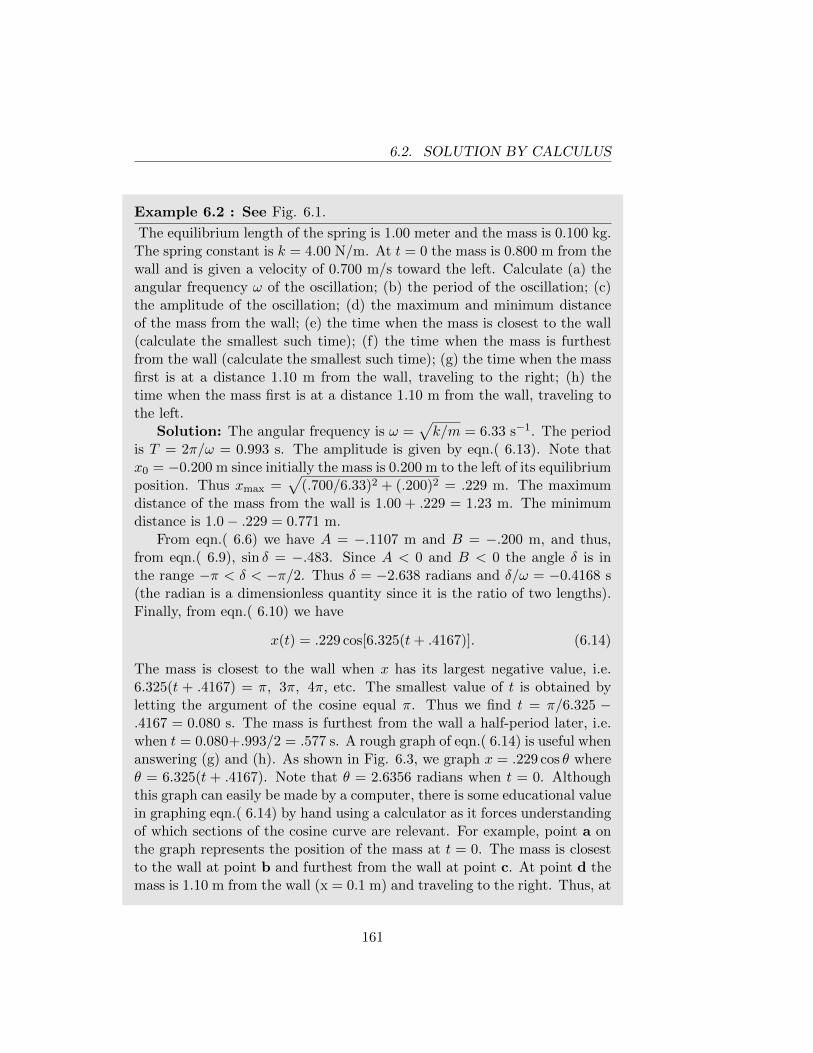
6.2. SOLUTION BY CALCULUS
Example 6.2 : See Fig. 6.1.
The equilibrium length of the spring is 1.00 meter and the mass is 0.100 kg.The spring constant is k = 4.00 N/m. At t = 0 the mass is 0.800 m from thewall and is given a velocity of 0.700 m/s toward the left. Calculate (a) theangular frequency ω of the oscillation; (b) the period of the oscillation; (c)the amplitude of the oscillation; (d) the maximum and minimum distanceof the mass from the wall; (e) the time when the mass is closest to the wall(calculate the smallest such time); (f) the time when the mass is furthestfrom the wall (calculate the smallest such time); (g) the time when the massfirst is at a distance 1.10 m from the wall, traveling to the right; (h) thetime when the mass first is at a distance 1.10 m from the wall, traveling tothe left.
Solution: The angular frequency is ω =√k/m = 6.33 s−1. The period
is T = 2π/ω = 0.993 s. The amplitude is given by eqn.( 6.13). Note thatx0 = −0.200 m since initially the mass is 0.200 m to the left of its equilibriumposition. Thus xmax =
√(.700/6.33)2 + (.200)2 = .229 m. The maximum
distance of the mass from the wall is 1.00 + .229 = 1.23 m. The minimumdistance is 1.0− .229 = 0.771 m.
From eqn.( 6.6) we have A = −.1107 m and B = −.200 m, and thus,from eqn.( 6.9), sin δ = −.483. Since A < 0 and B < 0 the angle δ is inthe range −π < δ < −π/2. Thus δ = −2.638 radians and δ/ω = −0.4168 s(the radian is a dimensionless quantity since it is the ratio of two lengths).Finally, from eqn.( 6.10) we have
x(t) = .229 cos[6.325(t+ .4167)]. (6.14)
The mass is closest to the wall when x has its largest negative value, i.e.6.325(t + .4167) = π, 3π, 4π, etc. The smallest value of t is obtained byletting the argument of the cosine equal π. Thus we find t = π/6.325 −.4167 = 0.080 s. The mass is furthest from the wall a half-period later, i.e.when t = 0.080+.993/2 = .577 s. A rough graph of eqn.( 6.14) is useful whenanswering (g) and (h). As shown in Fig. 6.3, we graph x = .229 cos θ whereθ = 6.325(t + .4167). Note that θ = 2.6356 radians when t = 0. Althoughthis graph can easily be made by a computer, there is some educational valuein graphing eqn.( 6.14) by hand using a calculator as it forces understandingof which sections of the cosine curve are relevant. For example, point a onthe graph represents the position of the mass at t = 0. The mass is closestto the wall at point b and furthest from the wall at point c. At point d themass is 1.10 m from the wall (x = 0.1 m) and traveling to the right. Thus, at
161
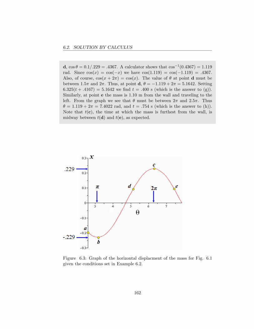
6.2. SOLUTION BY CALCULUS
d, cos θ = 0.1/.229 = .4367. A calculator shows that cos−1(0.4367) = 1.119rad. Since cos(x) = cos(−x) we have cos(1.119) = cos(−1.119) = .4367.Also, of course, cos(x + 2π) = cos(x). The value of θ at point d must bebetween 1.5π and 2π. Thus, at point d, θ = −1.119 + 2π = 5.1642. Setting6.325(t + .4167) = 5.1642 we find t = .400 s (which is the answer to (g)).Similarly, at point e the mass is 1.10 m from the wall and traveling to theleft. From the graph we see that θ must be between 2π and 2.5π. Thusθ = 1.119 + 2π = 7.4022 rad, and t = .754 s (which is the answer to (h)).Note that t(c), the time at which the mass is furthest from the wall, ismidway between t(d) and t(e), as expected.
Figure 6.3: Graph of the horizontal displacment of the mass for Fig. 6.1given the conditions set in Example 6.2.
162
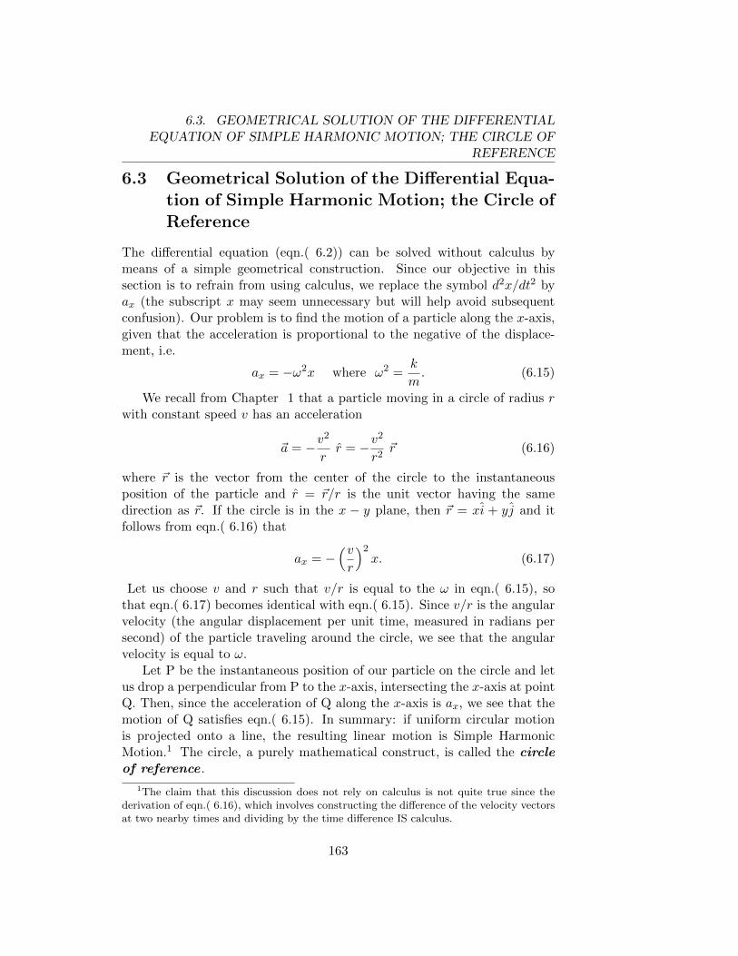
6.3. GEOMETRICAL SOLUTION OF THE DIFFERENTIALEQUATION OF SIMPLE HARMONIC MOTION; THE CIRCLE OF
REFERENCE
6.3 Geometrical Solution of the Differential Equa-tion of Simple Harmonic Motion; the Circle ofReference
The differential equation (eqn.( 6.2)) can be solved without calculus bymeans of a simple geometrical construction. Since our objective in thissection is to refrain from using calculus, we replace the symbol d2x/dt2 byax (the subscript x may seem unnecessary but will help avoid subsequentconfusion). Our problem is to find the motion of a particle along the x-axis,given that the acceleration is proportional to the negative of the displace-ment, i.e.
ax = −ω2x where ω2 =k
m. (6.15)
We recall from Chapter 1 that a particle moving in a circle of radius rwith constant speed v has an acceleration
~a = −v2
rr = −v
2
r2~r (6.16)
where ~r is the vector from the center of the circle to the instantaneousposition of the particle and r = ~r/r is the unit vector having the samedirection as ~r. If the circle is in the x − y plane, then ~r = xi + yj and itfollows from eqn.( 6.16) that
ax = −(vr
)2x. (6.17)
Let us choose v and r such that v/r is equal to the ω in eqn.( 6.15), sothat eqn.( 6.17) becomes identical with eqn.( 6.15). Since v/r is the angularvelocity (the angular displacement per unit time, measured in radians persecond) of the particle traveling around the circle, we see that the angularvelocity is equal to ω.
Let P be the instantaneous position of our particle on the circle and letus drop a perpendicular from P to the x-axis, intersecting the x-axis at pointQ. Then, since the acceleration of Q along the x-axis is ax, we see that themotion of Q satisfies eqn.( 6.15). In summary: if uniform circular motionis projected onto a line, the resulting linear motion is Simple HarmonicMotion.1 The circle, a purely mathematical construct, is called the circleof reference .
1The claim that this discussion does not rely on calculus is not quite true since thederivation of eqn.( 6.16), which involves constructing the difference of the velocity vectorsat two nearby times and dividing by the time difference IS calculus.
163
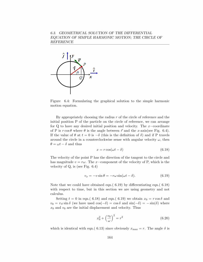
6.3. GEOMETRICAL SOLUTION OF THE DIFFERENTIALEQUATION OF SIMPLE HARMONIC MOTION; THE CIRCLE OFREFERENCE
Figure 6.4: Formulating the graphical solution to the simple harmonicmotion equation.
By appropriately choosing the radius r of the circle of reference and theinitial position P of the particle on the circle of reference, we can arrangefor Q to have any desired initial position and velocity. The x−coordinateof P is r cos θ where θ is the angle between ~r and the x-axis(see Fig. 6.4).If the value of θ at t = 0 is −δ (this is the definition of δ) and if P travelsaround the circle in a counterclockwise sense with angular velocity ω, thenθ = ωt− δ and thus
x = r cos(ωt− δ) (6.18)
The velocity of the point P has the direction of the tangent to the circle andhas magnitude v = rω. The x−component of the velocity of P, which is thevelocity of Q, is (see Fig. 6.4)
vx = −v sin θ = −rω sin(ωt− δ). (6.19)
Note that we could have obtained eqn.( 6.19) by differentiating eqn.( 6.18)with respect to time, but in this section we are using geometry and notcalculus.
Setting t = 0 in eqn.( 6.18) and eqn.( 6.19) we obtain x0 = r cos δ andv0 = rω sin δ (we have used cos(−δ) = cos δ and sin(−δ) = − sin(δ) wherex0 and v0 are the initial displacement and velocity. Thus
x20 +
(v0
ω
)2= r2 (6.20)
which is identical with eqn.( 6.13) since obviously xmax = r. The angle δ is
164
6.4. ENERGY CONSIDERATIONS IN SIMPLE HARMONIC MOTION
determined by
cos δ =x0
r=
x0√x2
0 + (v0/ω)2
sin δ =(v0/ω)√
x20 + (v0/ω)2
which are identical with eqn.( 6.8) and eqn.( 6.9). Thus we have obtainedall the equations of the previous section.
It is instructive to draw qualitatively correct graphs of x, vx, and axversus t by visualizing the motion of the point P on the circle of reference.You should compare your graphs with eqn.( 6.18) and eqn.( 6.19). Taket = 0 at the instant when x = xmax, i.e. θ = 0. It should be clear that thespeed is zero when x = ±xmax and the speed is greatest when x = 0.
6.4 Energy Considerations in Simple Harmonic Mo-tion
If the force on a particle is ~F = −kx i, then the work done on the particleas it goes from x0 to xf is (think of the path as a sequence of small stepsdx i)
W = −k∫ xf
x0
x dx = −1
2kx2
f +1
2kx2
0
(note that the force is conservative since the work depends only on theendpoints and does not depend on whether the particle went directly fromx0 to xf or backtracked during its path).
The work-energy theorem states
1
2mv2
f −1
2mv2
0 = −1
2kx2
f +1
2kx2
0
i.e.1
2mv2 +
1
2kx2 = constant = E (6.21)
Eqn.( 6.21) is already contained in our previous solution. Recall x =xmax cos(ωt − δ), v = −ωxmax sin(ωt − δ). Using ω2 = k/m and sin2 δ +cos2 δ = 1 we obtain
1
2mv2 +
1
2kx2 =
1
2kx2
max.
Since vmax = ωxmax we can write the energy as 12mv2
max or 12kx2
max. Werecognize 1
2kx2
max as the potential energy with the reference point taken
165
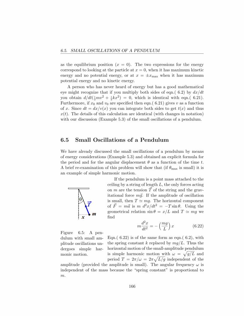
6.5. SMALL OSCILLATIONS OF A PENDULUM
as the equilibrium position (x = 0). The two expressions for the energycorrespond to looking at the particle at x = 0, when it has maximum kineticenergy and no potential energy, or at x = ±xmax when it has maximumpotential energy and no kinetic energy.
A person who has never heard of energy but has a good mathematicaleye might recognize that if you multiply both sides of eqn.( 6.2) by dx/dtyou obtain d/dt( 1
2mv2 + 1
2kx2) = 0, which is identical with eqn.( 6.21).
Furthermore, if x0 and v0 are specified then eqn.( 6.21) gives v as a functionof x. Since dt = dx/v(x) you can integrate both sides to get t(x) and thusx(t). The details of this calculation are identical (with changes in notation)with our discussion (Example 5.3) of the small oscillations of a pendulum.
6.5 Small Oscillations of a Pendulum
We have already discussed the small oscillations of a pendulum by meansof energy considerations (Example 5.3) and obtained an explicit formula forthe period and for the angular displacement θ as a function of the time t.A brief re-examination of this problem will show that (if θmax is small) it isan example of simple harmonic motion.
Figure 6.5: A pen-dulum with small am-plitude oscillations un-dergoes simple har-monic motion.
If the pendulum is a point mass attached to theceiling by a string of length L, the only forces actingon m are the tension ~T of the string and the grav-itational force m~g. If the amplitude of oscillationis small, then T ' mg. The horizontal componentof ~F = m~a is m d2x/dt2 = −T sin θ. Using thegeometrical relation sin θ = x/L and T ' mg wefind
md2x
dt2= −
(mgL
)x (6.22)
Eqn.( 6.22) is of the same form as eqn.( 6.2), withthe spring constant k replaced by mg/L. Thus thehorizontal motion of the small-amplitude pendulumis simple harmonic motion with ω =
√g/L and
period T = 2π/ω = 2π√L/g independent of the
amplitude (provided the amplitude is small). The angular frequency ω isindependent of the mass because the “spring constant” is proportional tom.
166
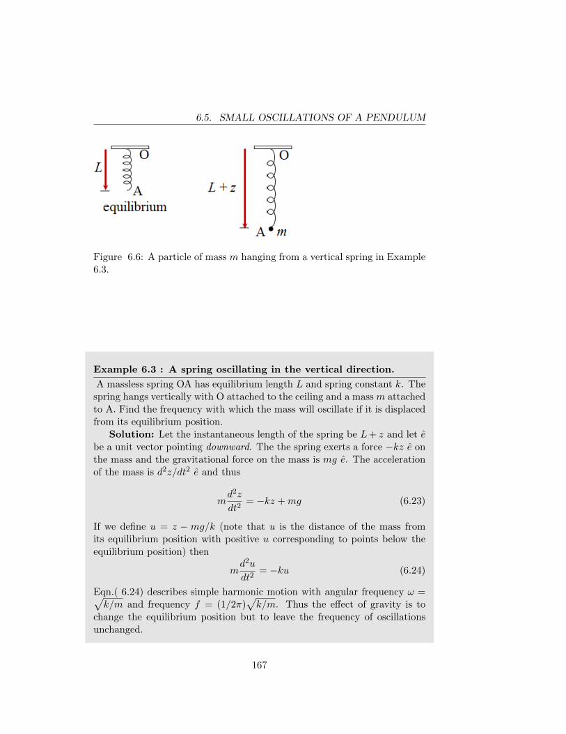
6.5. SMALL OSCILLATIONS OF A PENDULUM
Figure 6.6: A particle of mass m hanging from a vertical spring in Example6.3.
Example 6.3 : A spring oscillating in the vertical direction.
A massless spring OA has equilibrium length L and spring constant k. Thespring hangs vertically with O attached to the ceiling and a mass m attachedto A. Find the frequency with which the mass will oscillate if it is displacedfrom its equilibrium position.
Solution: Let the instantaneous length of the spring be L+ z and let ebe a unit vector pointing downward. The the spring exerts a force −kz e onthe mass and the gravitational force on the mass is mg e. The accelerationof the mass is d2z/dt2 e and thus
md2z
dt2= −kz +mg (6.23)
If we define u = z − mg/k (note that u is the distance of the mass fromits equilibrium position with positive u corresponding to points below theequilibrium position) then
md2u
dt2= −ku (6.24)
Eqn.( 6.24) describes simple harmonic motion with angular frequency ω =√k/m and frequency f = (1/2π)
√k/m. Thus the effect of gravity is to
change the equilibrium position but to leave the frequency of oscillationsunchanged.
167
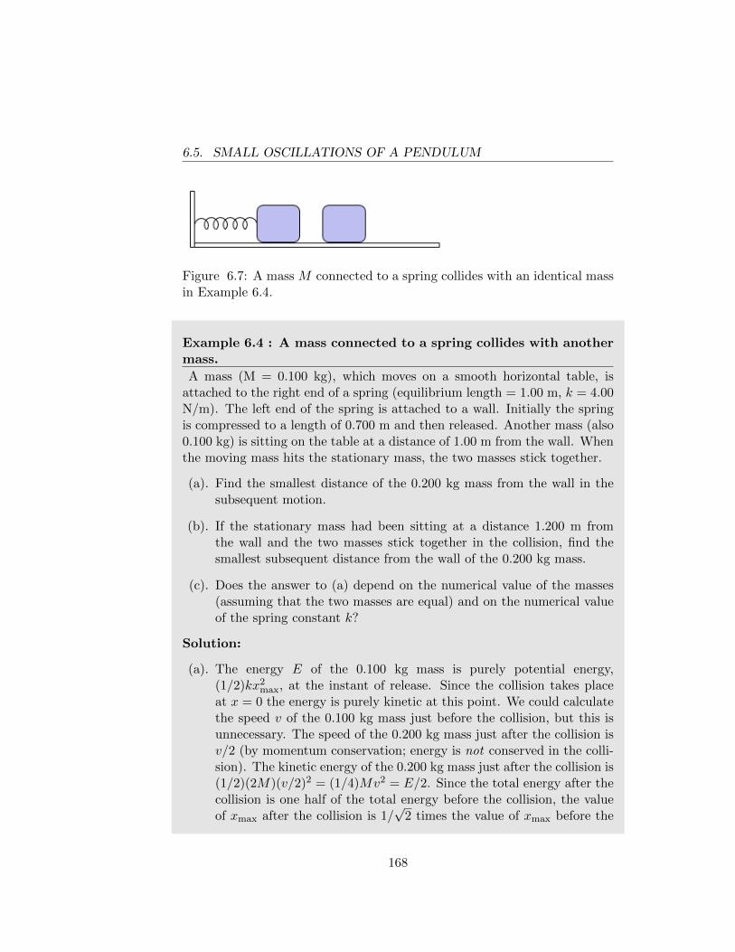
6.5. SMALL OSCILLATIONS OF A PENDULUM
Figure 6.7: A mass M connected to a spring collides with an identical massin Example 6.4.
Example 6.4 : A mass connected to a spring collides with anothermass.
A mass (M = 0.100 kg), which moves on a smooth horizontal table, isattached to the right end of a spring (equilibrium length = 1.00 m, k = 4.00N/m). The left end of the spring is attached to a wall. Initially the springis compressed to a length of 0.700 m and then released. Another mass (also0.100 kg) is sitting on the table at a distance of 1.00 m from the wall. Whenthe moving mass hits the stationary mass, the two masses stick together.
(a). Find the smallest distance of the 0.200 kg mass from the wall in thesubsequent motion.
(b). If the stationary mass had been sitting at a distance 1.200 m fromthe wall and the two masses stick together in the collision, find thesmallest subsequent distance from the wall of the 0.200 kg mass.
(c). Does the answer to (a) depend on the numerical value of the masses(assuming that the two masses are equal) and on the numerical valueof the spring constant k?
Solution:
(a). The energy E of the 0.100 kg mass is purely potential energy,(1/2)kx2
max, at the instant of release. Since the collision takes placeat x = 0 the energy is purely kinetic at this point. We could calculatethe speed v of the 0.100 kg mass just before the collision, but this isunnecessary. The speed of the 0.200 kg mass just after the collision isv/2 (by momentum conservation; energy is not conserved in the colli-sion). The kinetic energy of the 0.200 kg mass just after the collision is(1/2)(2M)(v/2)2 = (1/4)Mv2 = E/2. Since the total energy after thecollision is one half of the total energy before the collision, the valueof xmax after the collision is 1/
√2 times the value of xmax before the
168
6.5. SMALL OSCILLATIONS OF A PENDULUM
collision. Therefore, after the collision xmax = 0.3/1.414 = 0.212 mand the smallest distance from the wall is 1.0 - .212 = .788 m. Thisresult clearly did not depend on the numerical value M = 0.100 kg oron the value of k.
(b). Frequently it is more instructive to solve a problem in terms of symbols(representing the input quantities, like k and M) than to insert numer-ical values prematurely. If we do this we will see that that the answerto (b) also does not depend on the value of k or M . Let x0 denote thevalue of x at the point where M (= 0.100 kg) was initially released(x0 = −0.300 m). Let x1 denote the value of x at the point where thecollision occurs (x1 = 0.200 m). Before the collision the mass M hastotal energy (1/2)kx2
0. Just before the collision the mass M has thekinetic energy (1/2)kx2
0 − (1/2)kx21. Let Xmax denote the maximum
value of x in the motion after the collision. Then the total energy ofthe mass 2M after the collision is (1/2)kX2
max and the kinetic energyof the mass 2M just after the collision is (1/2)kX2
max − (1/2)kx21. We
have shown above that, when a moving particle hits a stationary par-ticle of the same mass and the two masses stick together, the kineticenergy just after the collision is one-half of the kinetic energy just be-fore the collision (As we noted in Chapter 4, a finite external force(the spring) acting during the infinitesimal time of the collision con-tributes no momentum to the system, so it is fine to use Conservationof Momentum.). Thus we find
1
2kX2
max −1
2kx2
1 =1
2
[12kx2
0 − 12kx2
1
].
Simple algebra yields(Xmax
x0
)2
=1
2
[1 +
(x1
x0
)2]. (6.25)
Inserting numbers, we find Xmax = .255 m and the smallest distancefrom the wall is 1.0 - .255 = .745 m. This solution made no use of thenumerical values of M or k.
(c). There are of course other (equivalent) ways to solve parts (a) and(b) of this problem, all of which will lead to eqn.( 6.25). A VERYIMPORTANT lesson can be learned here: even before solving the
169
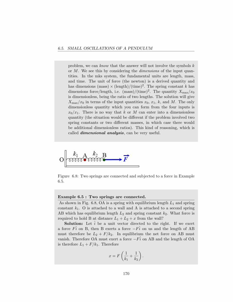
6.5. SMALL OSCILLATIONS OF A PENDULUM
problem, we can know that the answer will not involve the symbols kor M . We see this by considering the dimensions of the input quan-tities. In the mks system, the fundamental units are length, mass,and time. The unit of force (the newton) is a derived quantity andhas dimensions (mass)× (length)/(time)2. The spring constant k hasdimensions force/length, i.e. (mass)/(time)2. The quantity Xmax/x0
is dimensionless, being the ratio of two lengths. The solution will giveXmax/x0 in terms of the input quantities x0, x1, k, and M . The onlydimensionless quantity which you can form from the four inputs isx0/x1. There is no way that k or M can enter into a dimensionlessquantity (the situation would be different if the problem involved twospring constants or two different masses, in which case there wouldbe additional dimensionless ratios). This kind of reasoning, which iscalled dimensional analysis, can be very useful.
Figure 6.8: Two springs are connected and subjected to a force in Example6.5.
Example 6.5 : Two springs are connected.
As shown in Fig. 6.8, OA is a spring with equilibrium length L1 and springconstant k1. O is attached to a wall and A is attached to a second springAB which has equilibrium length L2 and spring constant k2. What force isrequired to hold B at distance L1 + L2 + x from the wall?
Solution: Let i be a unit vector directed to the right. If we exerta force F i on B, then B exerts a force −F i on us and the length of ABmust therefore be L2 + F/k2. In equilibrium the net force on AB mustvanish. Therefore OA must exert a force −F i on AB and the length of OAis therefore L1 + F/k1. Therefore
x = F
(1
k1+
1
k2
).
170
6.5. SMALL OSCILLATIONS OF A PENDULUM
If we write F = keqx (where keq is the spring constant of a single springequivalent to the combination), then
1
k eq=
1
k1+
1
k2⇒
keq =k1k2
k1 + k2.
If k1 = k2, then k = 12k1.
171
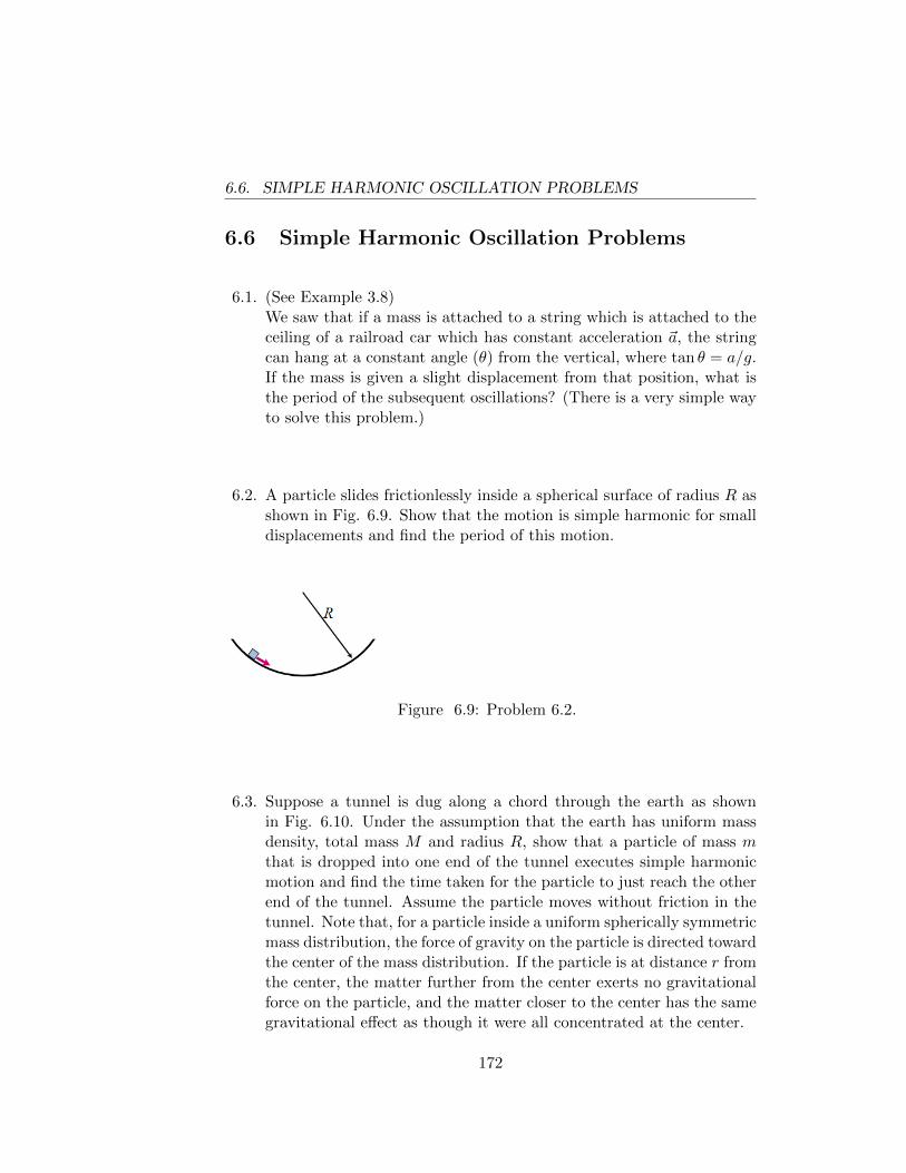
6.6. SIMPLE HARMONIC OSCILLATION PROBLEMS
6.6 Simple Harmonic Oscillation Problems
6.1. (See Example 3.8)We saw that if a mass is attached to a string which is attached to theceiling of a railroad car which has constant acceleration ~a, the stringcan hang at a constant angle (θ) from the vertical, where tan θ = a/g.If the mass is given a slight displacement from that position, what isthe period of the subsequent oscillations? (There is a very simple wayto solve this problem.)
6.2. A particle slides frictionlessly inside a spherical surface of radius R asshown in Fig. 6.9. Show that the motion is simple harmonic for smalldisplacements and find the period of this motion.
Figure 6.9: Problem 6.2.
6.3. Suppose a tunnel is dug along a chord through the earth as shownin Fig. 6.10. Under the assumption that the earth has uniform massdensity, total mass M and radius R, show that a particle of mass mthat is dropped into one end of the tunnel executes simple harmonicmotion and find the time taken for the particle to just reach the otherend of the tunnel. Assume the particle moves without friction in thetunnel. Note that, for a particle inside a uniform spherically symmetricmass distribution, the force of gravity on the particle is directed towardthe center of the mass distribution. If the particle is at distance r fromthe center, the matter further from the center exerts no gravitationalforce on the particle, and the matter closer to the center has the samegravitational effect as though it were all concentrated at the center.
172
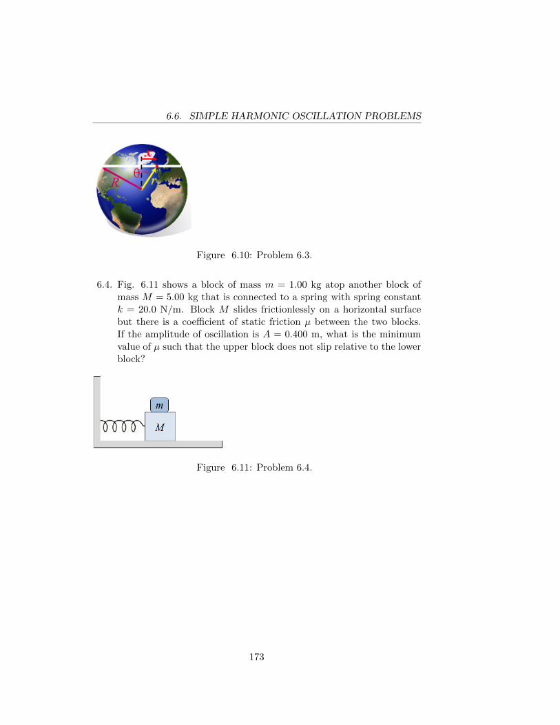
6.6. SIMPLE HARMONIC OSCILLATION PROBLEMS
Figure 6.10: Problem 6.3.
6.4. Fig. 6.11 shows a block of mass m = 1.00 kg atop another block ofmass M = 5.00 kg that is connected to a spring with spring constantk = 20.0 N/m. Block M slides frictionlessly on a horizontal surfacebut there is a coefficient of static friction µ between the two blocks.If the amplitude of oscillation is A = 0.400 m, what is the minimumvalue of µ such that the upper block does not slip relative to the lowerblock?
Figure 6.11: Problem 6.4.
173
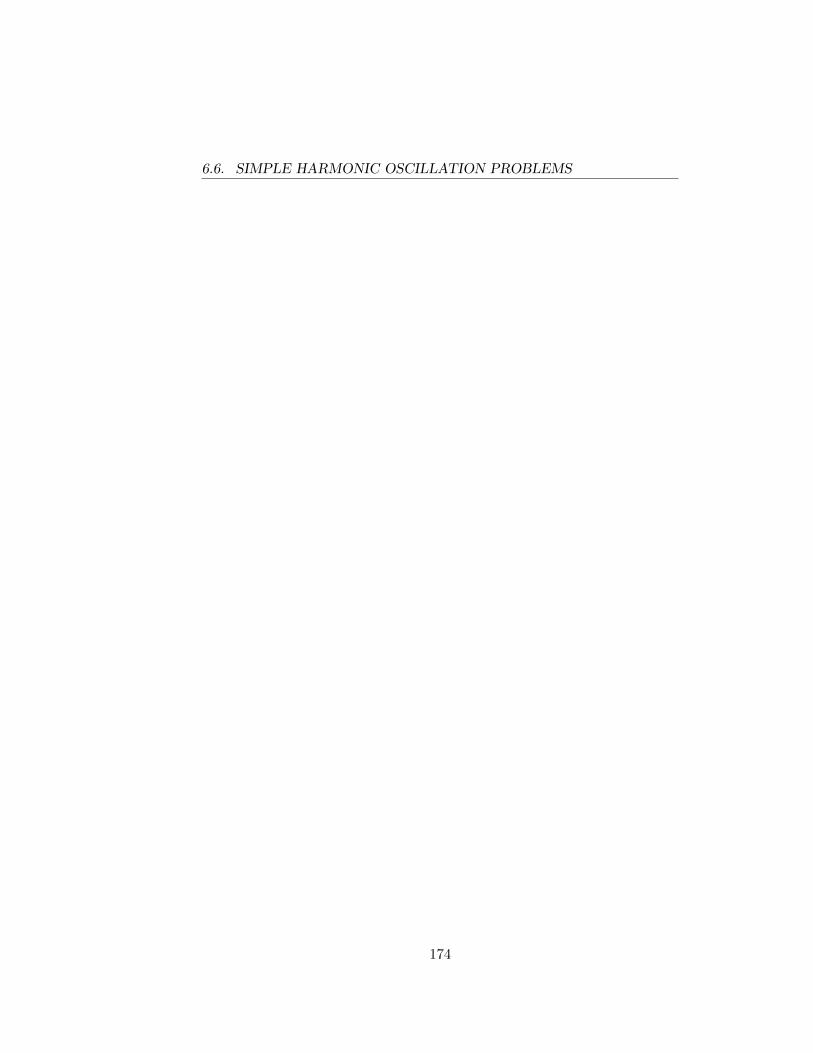
6.6. SIMPLE HARMONIC OSCILLATION PROBLEMS
174
Chapter 7
Static Equilibrium of SimpleRigid Bodies
[If the reader is not familiar with the vector cross-product, he/she shouldread the discussion of that subject in Appendix A.]
F
-F
Figure 7.1: Net force is zerobut the motion of the barchanges.
Until now we have concerned ourselvesmainly with the statics and dynamics ofpoint masses. The only significant state-ment we have made about the motion ofmore complicated systems was eqn.( 4.9),which states that (as a consequence of New-ton’s third law) the total external force act-ing on a system is equal to the total masstimes the acceleration of the center of mass.In particular, if the system is in equilibrium(i.e. every particle is at rest or moving withconstant velocity) the total external forcemust be zero. However, as we can see fromthe example illustrated in Fig. 7.1, the van-ishing of the total external force is not suf-ficient to ensure that the system will be inequilibrium. Under the infludence of the pair of equal and opposite forcesapplied to its ends, the rod in Fig. 7.1 will start to spin. In this chapter weshall be concerned with what conditions must be satisfied in order that abody may remain in equilibrium. In the following chapter we shall discusshow the body moves and spins when subjected to arbitrary forces.
The discussion of equilibrium relies heavily on the concept of torque,
175
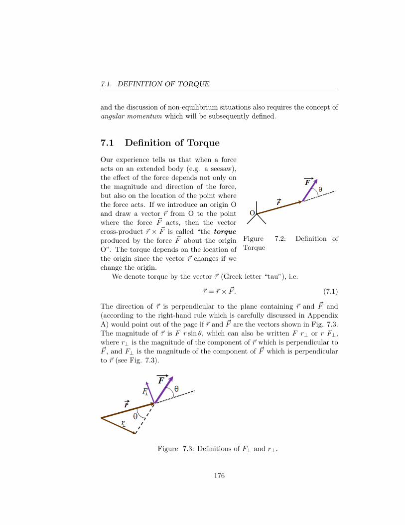
7.1. DEFINITION OF TORQUE
and the discussion of non-equilibrium situations also requires the concept ofangular momentum which will be subsequently defined.
7.1 Definition of Torque
Figure 7.2: Definition ofTorque
Our experience tells us that when a forceacts on an extended body (e.g. a seesaw),the effect of the force depends not only onthe magnitude and direction of the force,but also on the location of the point wherethe force acts. If we introduce an origin Oand draw a vector ~r from O to the pointwhere the force ~F acts, then the vectorcross-product ~r × ~F is called “the torqueproduced by the force ~F about the originO”. The torque depends on the location ofthe origin since the vector ~r changes if wechange the origin.
We denote torque by the vector ~τ (Greek letter “tau”), i.e.
~τ = ~r × ~F . (7.1)
The direction of ~τ is perpendicular to the plane containing ~r and ~F and(according to the right-hand rule which is carefully discussed in AppendixA) would point out of the page if ~r and ~F are the vectors shown in Fig. 7.3.The magnitude of ~τ is F r sin θ, which can also be written F r⊥ or r F⊥,where r⊥ is the magnitude of the component of ~r which is perpendicular to~F , and F⊥ is the magnitude of the component of ~F which is perpendicularto ~r (see Fig. 7.3).
Figure 7.3: Definitions of F⊥ and r⊥.
176
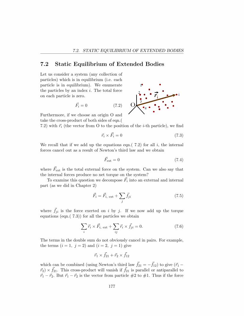
7.2. STATIC EQUILIBRIUM OF EXTENDED BODIES
7.2 Static Equilibrium of Extended Bodies
Let us consider a system (any collection ofparticles) which is in equilibrium (i.e. eachparticle is in equilibrium). We enumeratethe particles by an index i. The total forceon each particle is zero.
~Fi = 0 (7.2)
Furthermore, if we choose an origin O andtake the cross-product of both sides of eqn.(7.2) with ~ri (the vector from O to the position of the i-th particle), we find
~ri × ~Fi = 0 (7.3)
We recall that if we add up the equations eqn.( 7.2) for all i, the internalforces cancel out as a result of Newton’s third law and we obtain
~Fext = 0 (7.4)
where ~Fext is the total external force on the system. Can we also say thatthe internal forces produce no net torque on the system?
To examine this question we decompose ~Fi into an external and internalpart (as we did in Chapter 2)
~Fi = ~Fi, ext +∑j
~fji (7.5)
where ~fji is the force exerted on i by j. If we now add up the torqueequations (eqn.( 7.3)) for all the particles we obtain∑
i
~ri × ~Fi, ext +∑ij
~ri × ~fji = 0. (7.6)
The terms in the double sum do not obviously cancel in pairs. For example,the terms (i = 1, j = 2) and (i = 2, j = 1) give
~r1 × ~f21 + ~r2 × ~f12
which can be combined (using Newton’s third law ~f21 = −~f12) to give (~r1−~r2) × ~f21. This cross-product will vanish if ~f21 is parallel or antiparallel to~r1 − ~r2. But ~r1 − ~r2 is the vector from particle #2 to #1. Thus if the force
177
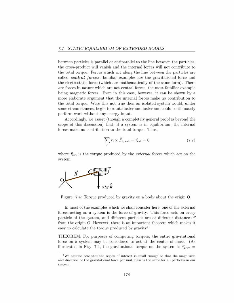
7.2. STATIC EQUILIBRIUM OF EXTENDED BODIES
between particles is parallel or antiparallel to the line between the particles,the cross-product will vanish and the internal forces will not contribute tothe total torque. Forces which act along the line between the particles arecalled central forces; familiar examples are the gravitational force andthe electrostatic force (which are mathematically of the same form). Thereare forces in nature which are not central forces, the most familiar examplebeing magnetic forces. Even in this case, however, it can be shown by amore elaborate argument that the internal forces make no contribution tothe total torque. Were this not true then an isolated system would, undersome circumstances, begin to rotate faster and faster and could continuouslyperform work without any energy input.
Accordingly, we assert (though a completely general proof is beyond thescope of this discussion) that, if a system is in equilibrium, the internalforces make no contribution to the total torque. Thus,∑
i
~ri × ~Fi, ext = ~τext = 0 (7.7)
where ~τext is the torque produced by the external forces which act on thesystem.
Figure 7.4: Torque produced by gravity on a body about the origin O.
In most of the examples which we shall consider here, one of the externalforces acting on a system is the force of gravity. This force acts on everyparticle of the system, and different particles are at different distances ~rfrom the origin O. However, there is an important theorem which makes iteasy to calculate the torque produced by gravity1.
THEOREM: For purposes of computing torques, the entire gravitationalforce on a system may be considered to act at the center of mass. (Asillustrated in Fig. 7.4, the gravitational torque on the system is ~τgrav =
1We assume here that the region of interest is small enough so that the magnitudeand direction of the gravitational force per unit mass is the same for all particles in oursystem.
178
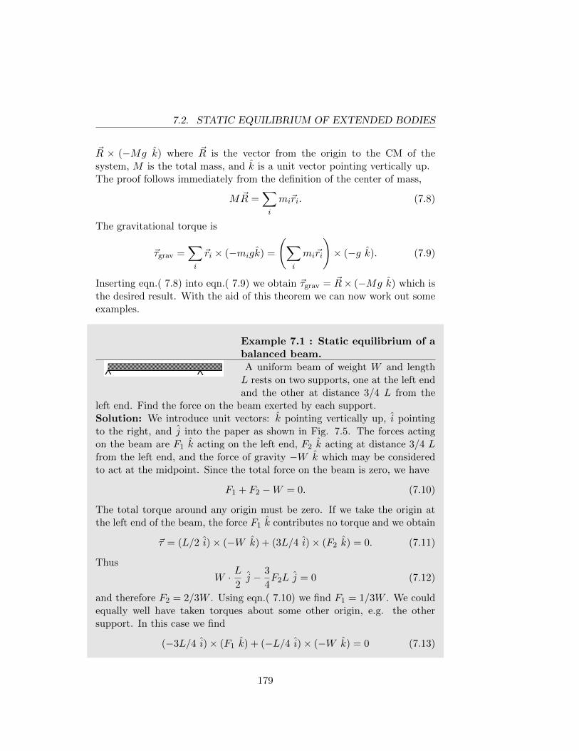
7.2. STATIC EQUILIBRIUM OF EXTENDED BODIES
~R × (−Mg k) where ~R is the vector from the origin to the CM of thesystem, M is the total mass, and k is a unit vector pointing vertically up.The proof follows immediately from the definition of the center of mass,
M ~R =∑i
mi~ri. (7.8)
The gravitational torque is
~τgrav =∑i
~ri × (−migk) =
(∑i
mi~ri
)× (−g k). (7.9)
Inserting eqn.( 7.8) into eqn.( 7.9) we obtain ~τgrav = ~R× (−Mg k) which isthe desired result. With the aid of this theorem we can now work out someexamples.
Example 7.1 : Static equilibrium of abalanced beam.
A uniform beam of weight W and lengthL rests on two supports, one at the left endand the other at distance 3/4 L from the
left end. Find the force on the beam exerted by each support.Solution: We introduce unit vectors: k pointing vertically up, i pointingto the right, and j into the paper as shown in Fig. 7.5. The forces actingon the beam are F1 k acting on the left end, F2 k acting at distance 3/4 Lfrom the left end, and the force of gravity −W k which may be consideredto act at the midpoint. Since the total force on the beam is zero, we have
F1 + F2 −W = 0. (7.10)
The total torque around any origin must be zero. If we take the origin atthe left end of the beam, the force F1 k contributes no torque and we obtain
~τ = (L/2 i)× (−W k) + (3L/4 i)× (F2 k) = 0. (7.11)
Thus
W · L2j − 3
4F2L j = 0 (7.12)
and therefore F2 = 2/3W . Using eqn.( 7.10) we find F1 = 1/3W . We couldequally well have taken torques about some other origin, e.g. the othersupport. In this case we find
(−3L/4 i)× (F1 k) + (−L/4 i)× (−W k) = 0 (7.13)
179
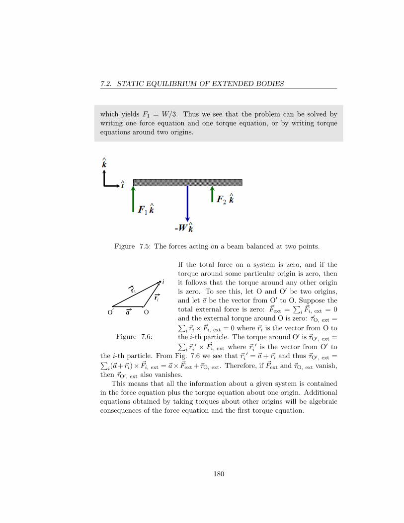
7.2. STATIC EQUILIBRIUM OF EXTENDED BODIES
which yields F1 = W/3. Thus we see that the problem can be solved bywriting one force equation and one torque equation, or by writing torqueequations around two origins.
Figure 7.5: The forces acting on a beam balanced at two points.
O O a
ri
i
Figure 7.6:
If the total force on a system is zero, and if thetorque around some particular origin is zero, thenit follows that the torque around any other originis zero. To see this, let O and O′ be two origins,and let ~a be the vector from O′ to O. Suppose thetotal external force is zero: ~Fext =
∑i~Fi, ext = 0
and the external torque around O is zero: ~τO, ext =∑i ~ri× ~Fi, ext = 0 where ~ri is the vector from O to
the i-th particle. The torque around O′ is ~τO′, ext =∑i ~r′i × ~Fi, ext where ~r ′i is the vector from O′ to
the i-th particle. From Fig. 7.6 we see that ~r ′i = ~a+ ~ri and thus ~τO′, ext =∑i(~a+ ~ri)× ~Fi, ext = ~a× ~Fext +~τO, ext. Therefore, if ~Fext and ~τO, ext vanish,
then ~τO′, ext also vanishes.This means that all the information about a given system is contained
in the force equation plus the torque equation about one origin. Additionalequations obtained by taking torques about other origins will be algebraicconsequences of the force equation and the first torque equation.
180
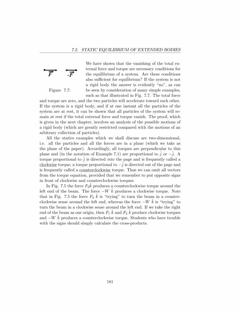
7.2. STATIC EQUILIBRIUM OF EXTENDED BODIES
Figure 7.7:
We have shown that the vanishing of the total ex-ternal force and torque are necessary conditions forthe equilibrium of a system. Are these conditionsalso sufficient for equilibrium? If the system is nota rigid body the answer is evidently “no”, as canbe seen by consideration of many simple examples,such as that illustrated in Fig. 7.7. The total force
and torque are zero, and the two particles will accelerate toward each other.If the system is a rigid body, and if at one instant all the particles of thesystem are at rest, it can be shown that all particles of the system will re-main at rest if the total external force and torque vanish. The proof, whichis given in the next chapter, involves an analysis of the possible motions ofa rigid body (which are greatly restricted compared with the motions of anarbitrary collection of particles).
All the statics examples which we shall discuss are two-dimensional,i.e. all the particles and all the forces are in a plane (which we take asthe plane of the paper). Accordingly, all torques are perpendicular to thisplane and (in the notation of Example 7.1) are proportional to j or −j. Atorque proportional to j is directed into the page and is frequently called aclockwise torque; a torque proportional to −j is directed out of the page andis frequently called a counterclockwise torque. Thus we can omit all vectorsfrom the torque equation, provided that we remember to put opposite signsin front of clockwise and counterclockwise torques.
In Fig. 7.5 the force F2k produces a counterclockwise torque around theleft end of the beam. The force −W k produces a clockwise torque. Notethat in Fig. 7.5 the force F2 k is “trying” to turn the beam in a counter-clockwise sense around the left end, whereas the force −W k is “trying” toturn the beam in a clockwise sense around the left end. If we take the rightend of the beam as our origin, then F1 k and F2 k produce clockwise torquesand −W k produces a counterclockwise torque. Students who have troublewith the signs should simply calculate the cross-products.
181
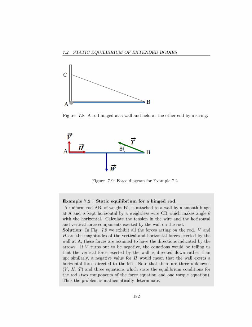
7.2. STATIC EQUILIBRIUM OF EXTENDED BODIES
Figure 7.8: A rod hinged at a wall and held at the other end by a string.
Figure 7.9: Force diagram for Example 7.2.
Example 7.2 : Static equilibrium for a hinged rod.
A uniform rod AB, of weight W , is attached to a wall by a smooth hingeat A and is kept horizontal by a weightless wire CB which makes angle θwith the horizontal. Calculate the tension in the wire and the horizontaland vertical force components exerted by the wall on the rod.Solution: In Fig. 7.9 we exhibit all the forces acting on the rod. V andH are the magnitudes of the vertical and horizontal forces exerted by thewall at A; these forces are assumed to have the directions indicated by thearrows. If V turns out to be negative, the equations would be telling usthat the vertical force exerted by the wall is directed down rather thanup; similarly, a negative value for H would mean that the wall exerts ahorizontal force directed to the left. Note that there are three unknowns(V , H, T ) and three equations which state the equilibrium conditions forthe rod (two components of the force equation and one torque equation).Thus the problem is mathematically determinate.
182
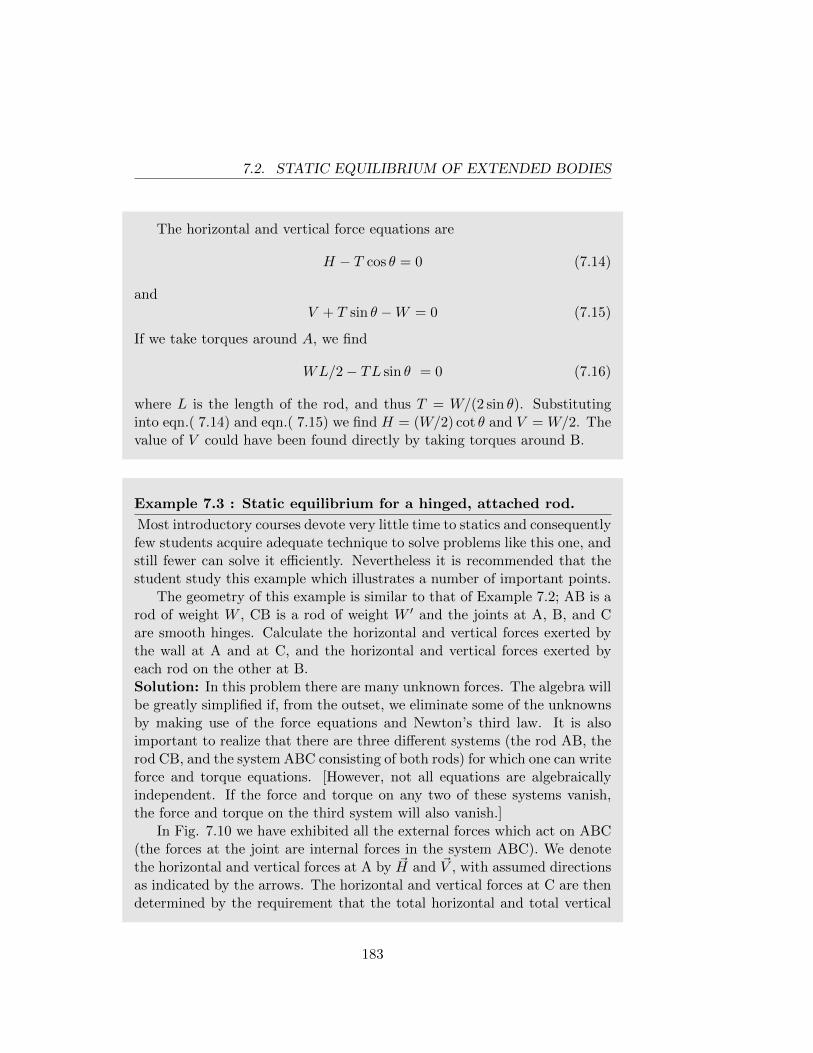
7.2. STATIC EQUILIBRIUM OF EXTENDED BODIES
The horizontal and vertical force equations are
H − T cos θ = 0 (7.14)
andV + T sin θ −W = 0 (7.15)
If we take torques around A, we find
WL/2− TL sin θ = 0 (7.16)
where L is the length of the rod, and thus T = W/(2 sin θ). Substitutinginto eqn.( 7.14) and eqn.( 7.15) we find H = (W/2) cot θ and V = W/2. Thevalue of V could have been found directly by taking torques around B.
Example 7.3 : Static equilibrium for a hinged, attached rod.
Most introductory courses devote very little time to statics and consequentlyfew students acquire adequate technique to solve problems like this one, andstill fewer can solve it efficiently. Nevertheless it is recommended that thestudent study this example which illustrates a number of important points.
The geometry of this example is similar to that of Example 7.2; AB is arod of weight W , CB is a rod of weight W ′ and the joints at A, B, and Care smooth hinges. Calculate the horizontal and vertical forces exerted bythe wall at A and at C, and the horizontal and vertical forces exerted byeach rod on the other at B.Solution: In this problem there are many unknown forces. The algebra willbe greatly simplified if, from the outset, we eliminate some of the unknownsby making use of the force equations and Newton’s third law. It is alsoimportant to realize that there are three different systems (the rod AB, therod CB, and the system ABC consisting of both rods) for which one can writeforce and torque equations. [However, not all equations are algebraicallyindependent. If the force and torque on any two of these systems vanish,the force and torque on the third system will also vanish.]
In Fig. 7.10 we have exhibited all the external forces which act on ABC(the forces at the joint are internal forces in the system ABC). We denotethe horizontal and vertical forces at A by ~H and ~V , with assumed directionsas indicated by the arrows. The horizontal and vertical forces at C are thendetermined by the requirement that the total horizontal and total vertical
183
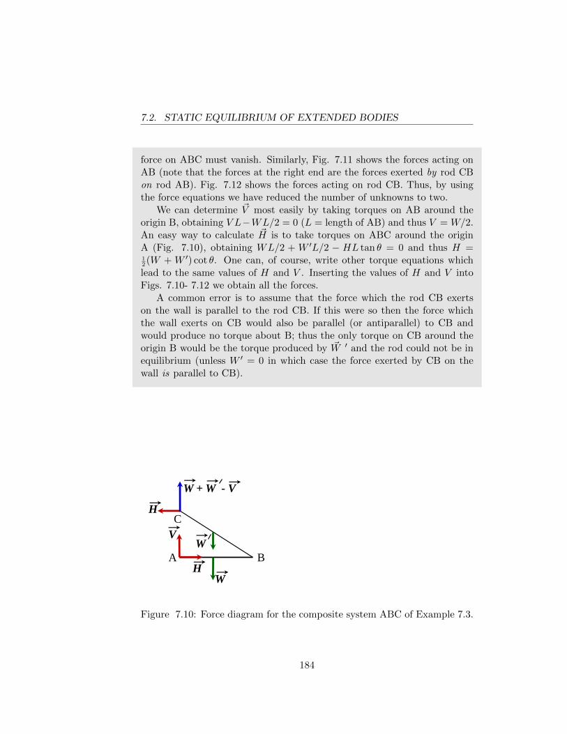
7.2. STATIC EQUILIBRIUM OF EXTENDED BODIES
force on ABC must vanish. Similarly, Fig. 7.11 shows the forces acting onAB (note that the forces at the right end are the forces exerted by rod CBon rod AB). Fig. 7.12 shows the forces acting on rod CB. Thus, by usingthe force equations we have reduced the number of unknowns to two.
We can determine ~V most easily by taking torques on AB around theorigin B, obtaining V L−WL/2 = 0 (L = length of AB) and thus V = W/2.An easy way to calculate ~H is to take torques on ABC around the originA (Fig. 7.10), obtaining WL/2 + W ′L/2 − HL tan θ = 0 and thus H =12(W + W ′) cot θ. One can, of course, write other torque equations which
lead to the same values of H and V . Inserting the values of H and V intoFigs. 7.10- 7.12 we obtain all the forces.
A common error is to assume that the force which the rod CB exertson the wall is parallel to the rod CB. If this were so then the force whichthe wall exerts on CB would also be parallel (or antiparallel) to CB andwould produce no torque about B; thus the only torque on CB around theorigin B would be the torque produced by ~W ′ and the rod could not be inequilibrium (unless W ′ = 0 in which case the force exerted by CB on thewall is parallel to CB).
W + W - V
A B
V
C
H
H
W
W
Figure 7.10: Force diagram for the composite system ABC of Example 7.3.
184
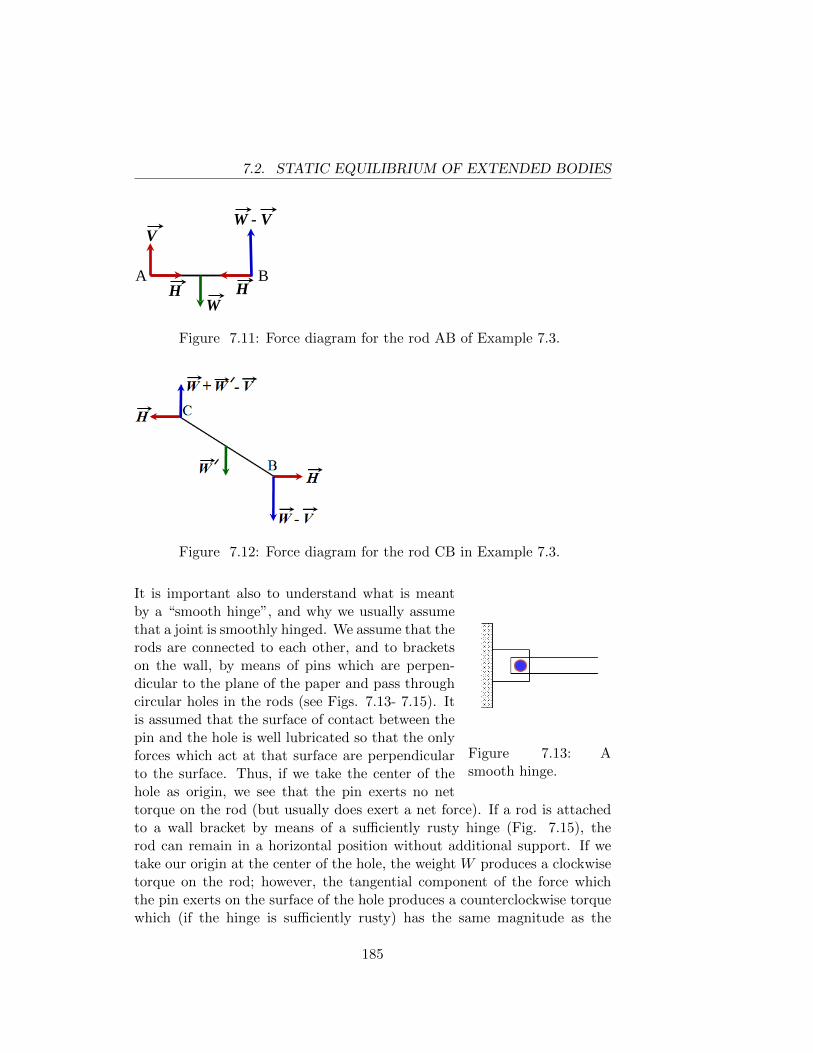
7.2. STATIC EQUILIBRIUM OF EXTENDED BODIES
A B H H
W
W - V V
Figure 7.11: Force diagram for the rod AB of Example 7.3.
Figure 7.12: Force diagram for the rod CB in Example 7.3.
Figure 7.13: Asmooth hinge.
It is important also to understand what is meantby a “smooth hinge”, and why we usually assumethat a joint is smoothly hinged. We assume that therods are connected to each other, and to bracketson the wall, by means of pins which are perpen-dicular to the plane of the paper and pass throughcircular holes in the rods (see Figs. 7.13- 7.15). Itis assumed that the surface of contact between thepin and the hole is well lubricated so that the onlyforces which act at that surface are perpendicularto the surface. Thus, if we take the center of thehole as origin, we see that the pin exerts no nettorque on the rod (but usually does exert a net force). If a rod is attachedto a wall bracket by means of a sufficiently rusty hinge (Fig. 7.15), therod can remain in a horizontal position without additional support. If wetake our origin at the center of the hole, the weight W produces a clockwisetorque on the rod; however, the tangential component of the force whichthe pin exerts on the surface of the hole produces a counterclockwise torquewhich (if the hinge is sufficiently rusty) has the same magnitude as the
185
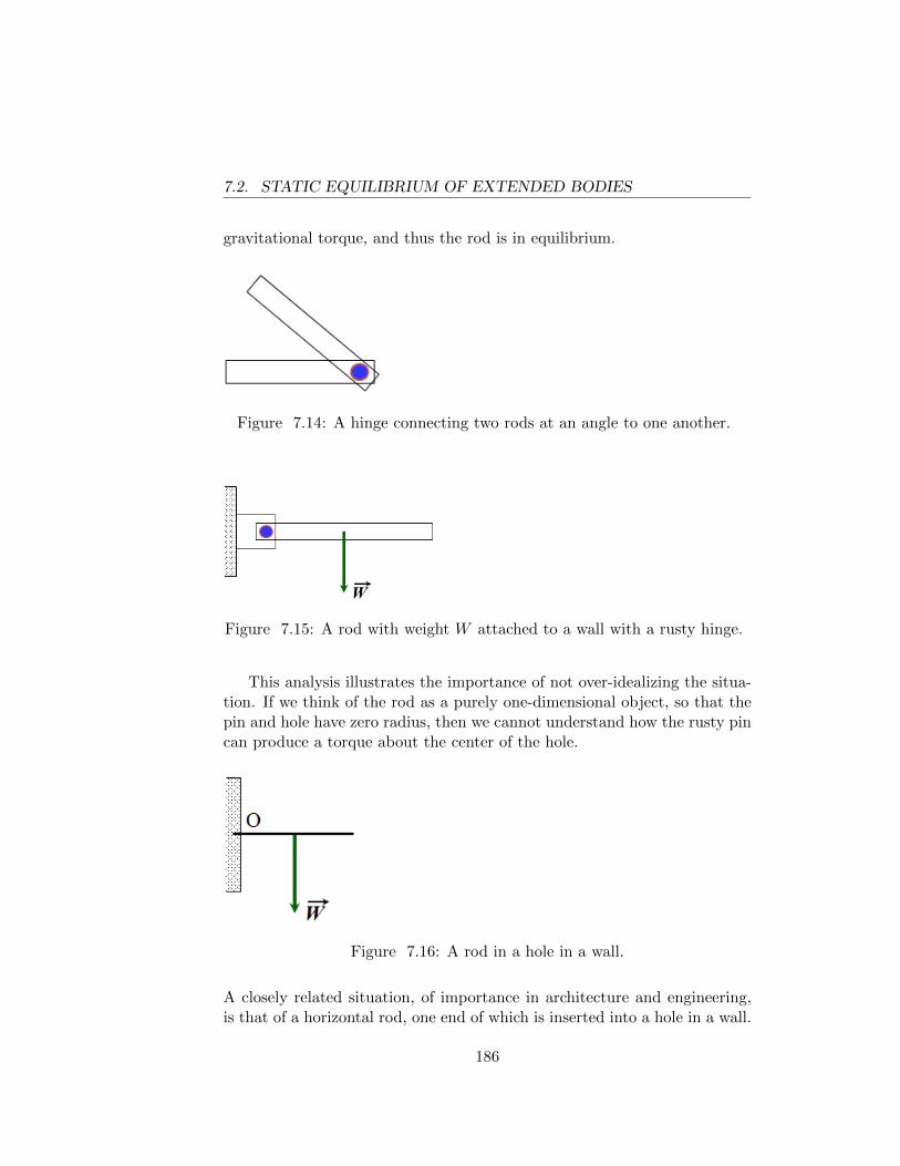
7.2. STATIC EQUILIBRIUM OF EXTENDED BODIES
gravitational torque, and thus the rod is in equilibrium.
Figure 7.14: A hinge connecting two rods at an angle to one another.
Figure 7.15: A rod with weight W attached to a wall with a rusty hinge.
This analysis illustrates the importance of not over-idealizing the situa-tion. If we think of the rod as a purely one-dimensional object, so that thepin and hole have zero radius, then we cannot understand how the rusty pincan produce a torque about the center of the hole.
Figure 7.16: A rod in a hole in a wall.
A closely related situation, of importance in architecture and engineering,is that of a horizontal rod, one end of which is inserted into a hole in a wall.
186
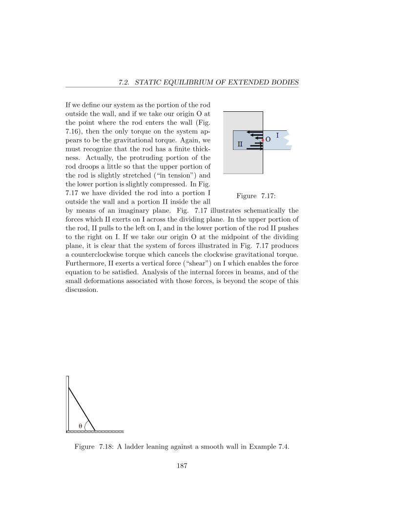
7.2. STATIC EQUILIBRIUM OF EXTENDED BODIES
Figure 7.17:
If we define our system as the portion of the rodoutside the wall, and if we take our origin O atthe point where the rod enters the wall (Fig.7.16), then the only torque on the system ap-pears to be the gravitational torque. Again, wemust recognize that the rod has a finite thick-ness. Actually, the protruding portion of therod droops a little so that the upper portion ofthe rod is slightly stretched (“in tension”) andthe lower portion is slightly compressed. In Fig.7.17 we have divided the rod into a portion Ioutside the wall and a portion II inside the allby means of an imaginary plane. Fig. 7.17 illustrates schematically theforces which II exerts on I across the dividing plane. In the upper portion ofthe rod, II pulls to the left on I, and in the lower portion of the rod II pushesto the right on I. If we take our origin O at the midpoint of the dividingplane, it is clear that the system of forces illustrated in Fig. 7.17 producesa counterclockwise torque which cancels the clockwise gravitational torque.Furthermore, II exerts a vertical force (“shear”) on I which enables the forceequation to be satisfied. Analysis of the internal forces in beams, and of thesmall deformations associated with those forces, is beyond the scope of thisdiscussion.
Figure 7.18: A ladder leaning against a smooth wall in Example 7.4.
187
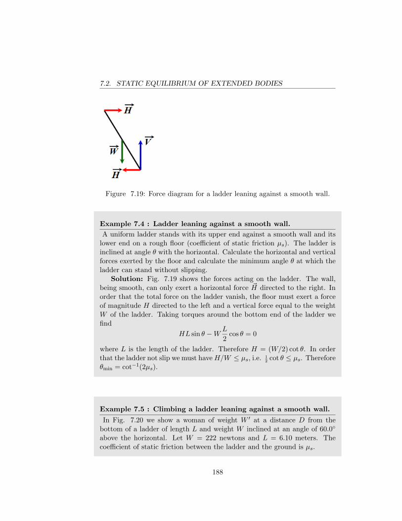
7.2. STATIC EQUILIBRIUM OF EXTENDED BODIES
Figure 7.19: Force diagram for a ladder leaning against a smooth wall.
Example 7.4 : Ladder leaning against a smooth wall.
A uniform ladder stands with its upper end against a smooth wall and itslower end on a rough floor (coefficient of static friction µs). The ladder isinclined at angle θ with the horizontal. Calculate the horizontal and verticalforces exerted by the floor and calculate the minimum angle θ at which theladder can stand without slipping.
Solution: Fig. 7.19 shows the forces acting on the ladder. The wall,being smooth, can only exert a horizontal force ~H directed to the right. Inorder that the total force on the ladder vanish, the floor must exert a forceof magnitude H directed to the left and a vertical force equal to the weightW of the ladder. Taking torques around the bottom end of the ladder wefind
HL sin θ −W L
2cos θ = 0
where L is the length of the ladder. Therefore H = (W/2) cot θ. In orderthat the ladder not slip we must haveH/W ≤ µs, i.e. 1
2cot θ ≤ µs. Therefore
θmin = cot−1(2µs).
Example 7.5 : Climbing a ladder leaning against a smooth wall.
In Fig. 7.20 we show a woman of weight W ′ at a distance D from thebottom of a ladder of length L and weight W inclined at an angle of 60.0◦
above the horizontal. Let W = 222 newtons and L = 6.10 meters. Thecoefficient of static friction between the ladder and the ground is µs.
188
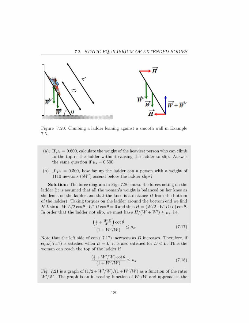
7.2. STATIC EQUILIBRIUM OF EXTENDED BODIES
Figure 7.20: Climbing a ladder leaning against a smooth wall in Example7.5.
(a). If µs = 0.600, calculate the weight of the heaviest person who can climbto the top of the ladder without causing the ladder to slip. Answerthe same question if µs = 0.500.
(b). If µs = 0.500, how far up the ladder can a person with a weight of1110 newtons (5W ′) ascend before the ladder slips?
Solution: The force diagram in Fig. 7.20 shows the forces acting on theladder (it is assumed that all the woman’s weight is balanced on her knee asshe leans on the ladder and that the knee is a distance D from the bottomof the ladder). Taking torques on the ladder around the bottom end we findH L sin θ−W L/2 cos θ−W ′ D cos θ = 0 and thusH = (W/2+W ′D/L) cot θ.In order that the ladder not slip, we must have H/(W +W ′) ≤ µs, i.e.(
12
+ W ′DWL
)cot θ
(1 +W ′/W )≤ µs. (7.17)
Note that the left side of eqn.( 7.17) increases as D increases. Therefore, ifeqn.( 7.17) is satisfied when D = L, it is also satisfied for D < L. Thus thewoman can reach the top of the ladder if
( 12
+W ′/W ) cot θ
(1 +W ′/W )≤ µs. (7.18)
Fig. 7.21 is a graph of (1/2 +W ′/W )/(1 +W ′/W ) as a function of the ratioW ′/W . The graph is an increasing function of W ′/W and approaches the
189
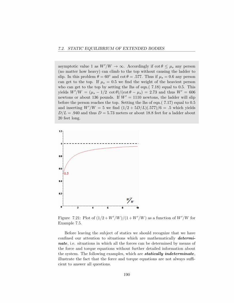
7.2. STATIC EQUILIBRIUM OF EXTENDED BODIES
asymptotic value 1 as W ′/W → ∞. Accordingly if cot θ ≤ µs any person(no matter how heavy) can climb to the top without causing the ladder toslip. In this problem θ = 60◦ and cot θ = .577. Thus if µs = 0.6 any personcan get to the top. If µs = 0.5 we find the weight of the heaviest personwho can get to the top by setting the lhs of eqn.( 7.18) equal to 0.5. Thisyields W ′/W = (µs − 1/2 cot θ)/(cot θ − µs) = 2.73 and thus W ′ = 606newtons or about 136 pounds. If W ′ = 1110 newtons, the ladder will slipbefore the person reaches the top. Setting the lhs of eqn.( 7.17) equal to 0.5and inserting W ′/W = 5 we find (1/2 + 5D/L)(.577)/6 = .5 which yieldsD/L = .940 and thus D = 5.73 meters or about 18.8 feet for a ladder about20 feet long.
Figure 7.21: Plot of (1/2 +W ′/W )/(1 +W ′/W ) as a function of W ′/W forExample 7.5.
Before leaving the subject of statics we should recognize that we haveconfined our attention to situations which are mathematically determi-nate , i.e. situations in which all the forces can be determined by means ofthe force and torque equations without further detailed information aboutthe system. The following examples, which are statically indeterminate ,illustrate the fact that the force and torque equations are not always suffi-cient to answer all questions.
190
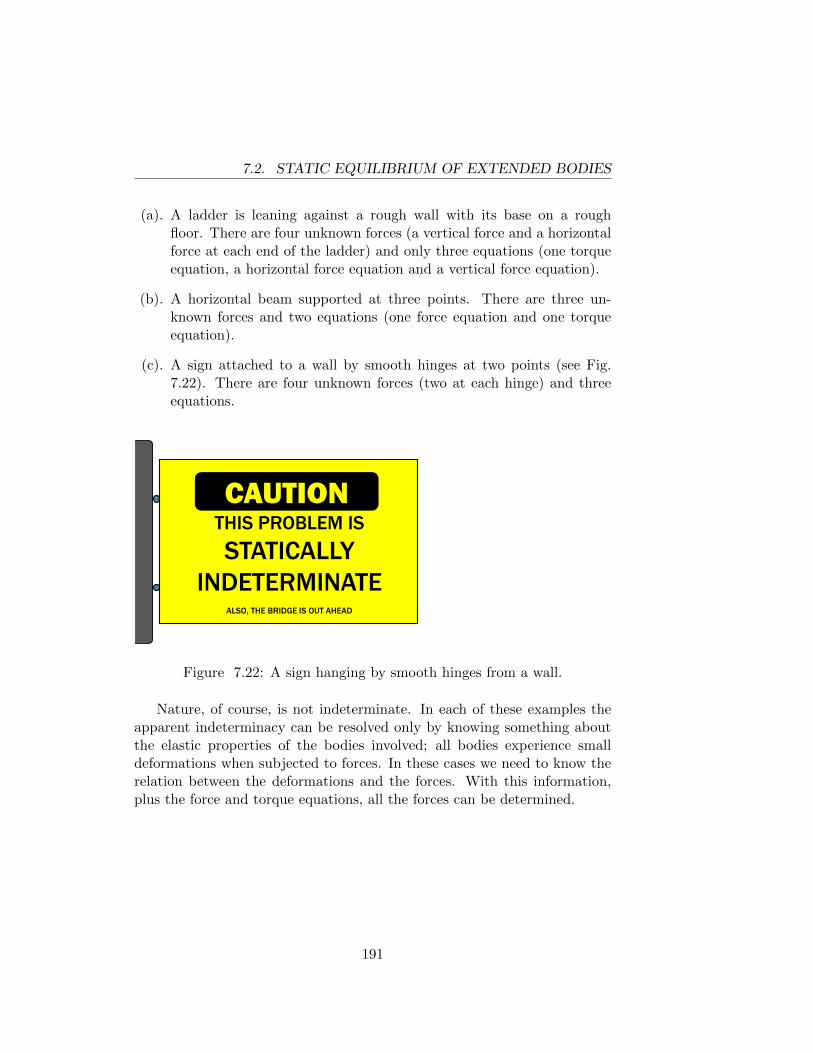
7.2. STATIC EQUILIBRIUM OF EXTENDED BODIES
(a). A ladder is leaning against a rough wall with its base on a roughfloor. There are four unknown forces (a vertical force and a horizontalforce at each end of the ladder) and only three equations (one torqueequation, a horizontal force equation and a vertical force equation).
(b). A horizontal beam supported at three points. There are three un-known forces and two equations (one force equation and one torqueequation).
(c). A sign attached to a wall by smooth hinges at two points (see Fig.7.22). There are four unknown forces (two at each hinge) and threeequations.
CAUTION THIS SIGN HAS
SHARP EDGES DO NOT TOUCH THE EDGES OF THIS SIGN
ALSO, THE BRIDGE IS OUT AHEAD
CAUTION THIS PROBLEM IS STATICALLY
INDETERMINATE ALSO, THE BRIDGE IS OUT AHEAD
Figure 7.22: A sign hanging by smooth hinges from a wall.
Nature, of course, is not indeterminate. In each of these examples theapparent indeterminacy can be resolved only by knowing something aboutthe elastic properties of the bodies involved; all bodies experience smalldeformations when subjected to forces. In these cases we need to know therelation between the deformations and the forces. With this information,plus the force and torque equations, all the forces can be determined.
191
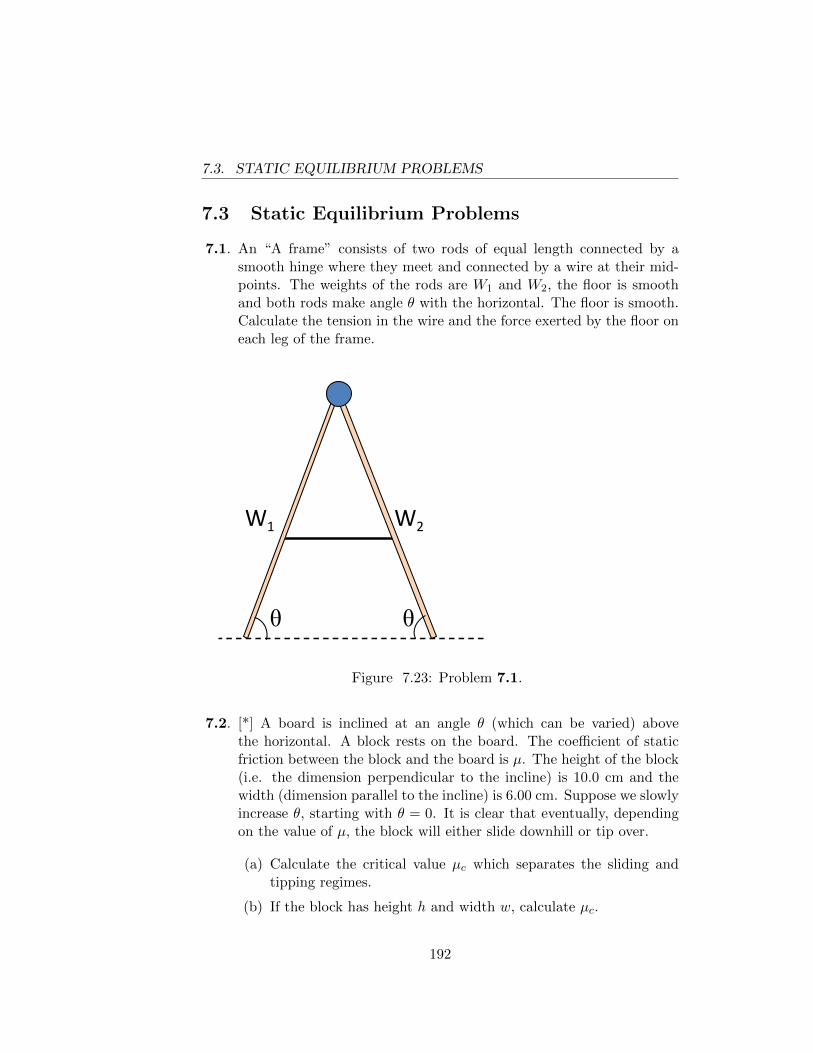
7.3. STATIC EQUILIBRIUM PROBLEMS
7.3 Static Equilibrium Problems
7.1. An “A frame” consists of two rods of equal length connected by asmooth hinge where they meet and connected by a wire at their mid-points. The weights of the rods are W1 and W2, the floor is smoothand both rods make angle θ with the horizontal. The floor is smooth.Calculate the tension in the wire and the force exerted by the floor oneach leg of the frame.
θ θ
θ θ
W1 W2
Figure 7.23: Problem 7.1.
7.2. [*] A board is inclined at an angle θ (which can be varied) abovethe horizontal. A block rests on the board. The coefficient of staticfriction between the block and the board is µ. The height of the block(i.e. the dimension perpendicular to the incline) is 10.0 cm and thewidth (dimension parallel to the incline) is 6.00 cm. Suppose we slowlyincrease θ, starting with θ = 0. It is clear that eventually, dependingon the value of µ, the block will either slide downhill or tip over.
(a) Calculate the critical value µc which separates the sliding andtipping regimes.
(b) If the block has height h and width w, calculate µc.
192
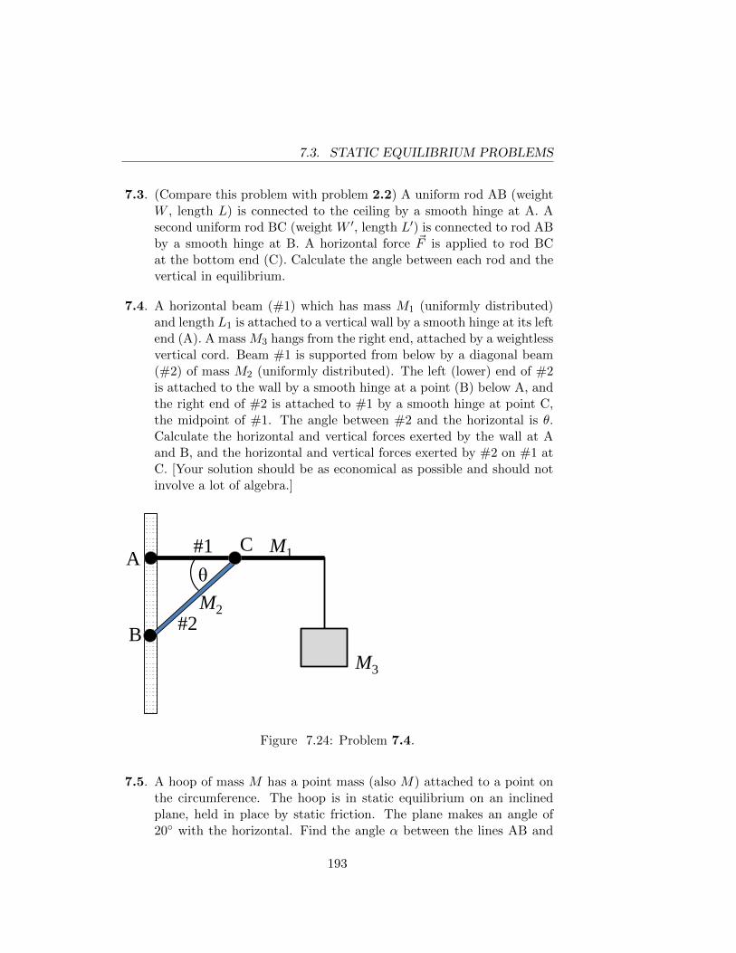
7.3. STATIC EQUILIBRIUM PROBLEMS
7.3. (Compare this problem with problem 2.2) A uniform rod AB (weightW , length L) is connected to the ceiling by a smooth hinge at A. Asecond uniform rod BC (weight W ′, length L′) is connected to rod ABby a smooth hinge at B. A horizontal force ~F is applied to rod BCat the bottom end (C). Calculate the angle between each rod and thevertical in equilibrium.
7.4. A horizontal beam (#1) which has mass M1 (uniformly distributed)and length L1 is attached to a vertical wall by a smooth hinge at its leftend (A). A mass M3 hangs from the right end, attached by a weightlessvertical cord. Beam #1 is supported from below by a diagonal beam(#2) of mass M2 (uniformly distributed). The left (lower) end of #2is attached to the wall by a smooth hinge at a point (B) below A, andthe right end of #2 is attached to #1 by a smooth hinge at point C,the midpoint of #1. The angle between #2 and the horizontal is θ.Calculate the horizontal and vertical forces exerted by the wall at Aand B, and the horizontal and vertical forces exerted by #2 on #1 atC. [Your solution should be as economical as possible and should notinvolve a lot of algebra.]
A C
B M3
M1
M2
#1
#2
θ
Figure 7.24: Problem 7.4.
7.5. A hoop of mass M has a point mass (also M) attached to a point onthe circumference. The hoop is in static equilibrium on an inclinedplane, held in place by static friction. The plane makes an angle of20◦ with the horizontal. Find the angle α between the lines AB and
193
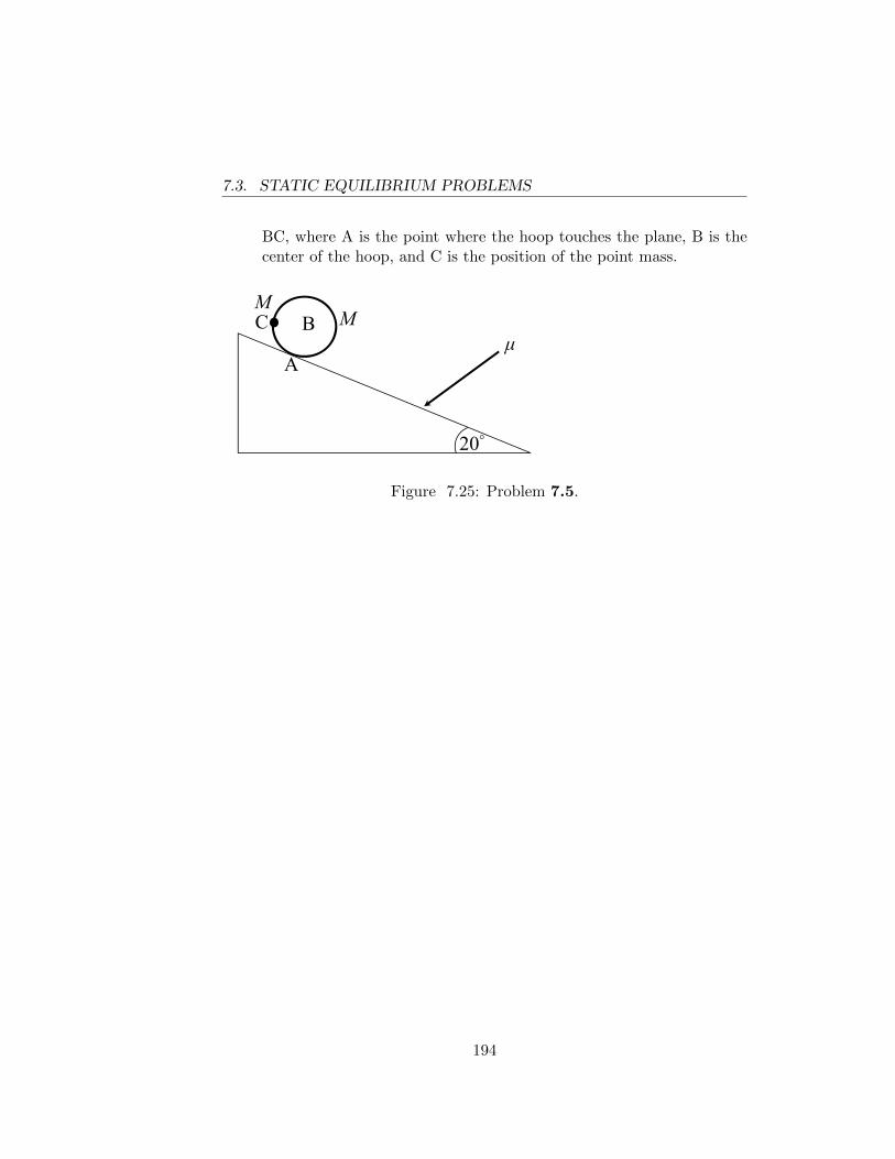
7.3. STATIC EQUILIBRIUM PROBLEMS
BC, where A is the point where the hoop touches the plane, B is thecenter of the hoop, and C is the position of the point mass.
μ
20°
A
BM
R
C M
AB
BCα
70°Figure 7.25: Problem 7.5.
194
Chapter 8
Rotational Motion, AngularMomentum and Dynamics ofRigid Bodies
Recall that an inertial frame is a set of axes such that, if you measurepositions and velocities with respect to those axes, Newton’s first law istrue, i.e. a particle subject to no forces will move with constant velocity. Inparticular, the axes of an inertial frame must be non-rotating with respectto the background of the distant stars. Regarding the motion of the originof an inertial frame, there is some arbitrariness due to imprecision in thenotion of “no force”. We shall assume here that we understand the meaningof “inertial frame” well enough to solve elementary problems.
Consider a particle of mass m whose position vector with respect to theorigin O of an inertial frame is ~r and whose velocity and acceleration are~v = d~r/dt and ~a = d~v/dt = d2~r/dt2. Taking the cross-product of both sidesof the equation of motion ~F = m~a with ~r we obtain
~r × ~F = m~r × ~a (8.1)
where ~F is the total force acting on the particle. The left side of eqn.( 8.1)is, of course, the torque ~τ (about the origin O) acting on the particle. Wealso define the angular momentum ~L of the particle about the origin Oby the equation
~L = m ~r × ~v (8.2)
Using the rule for differentiating a cross-product (see Appendix A) we find
d~L
dt= m ~v × ~v +m ~r × ~a. (8.3)
195
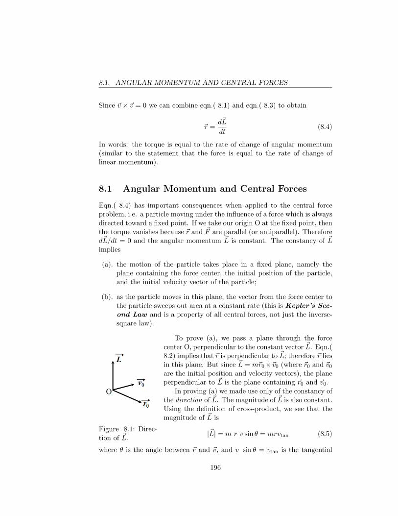
8.1. ANGULAR MOMENTUM AND CENTRAL FORCES
Since ~v × ~v = 0 we can combine eqn.( 8.1) and eqn.( 8.3) to obtain
~τ =d~L
dt(8.4)
In words: the torque is equal to the rate of change of angular momentum(similar to the statement that the force is equal to the rate of change oflinear momentum).
8.1 Angular Momentum and Central Forces
Eqn.( 8.4) has important consequences when applied to the central forceproblem, i.e. a particle moving under the influence of a force which is alwaysdirected toward a fixed point. If we take our origin O at the fixed point, thenthe torque vanishes because ~r and ~F are parallel (or antiparallel). Therefored~L/dt = 0 and the angular momentum ~L is constant. The constancy of ~Limplies
(a). the motion of the particle takes place in a fixed plane, namely theplane containing the force center, the initial position of the particle,and the initial velocity vector of the particle;
(b). as the particle moves in this plane, the vector from the force center tothe particle sweeps out area at a constant rate (this is Kepler’s Sec-ond Law and is a property of all central forces, not just the inverse-square law).
Figure 8.1: Direc-tion of ~L.
To prove (a), we pass a plane through the forcecenter O, perpendicular to the constant vector ~L. Eqn.(8.2) implies that ~r is perpendicular to ~L; therefore ~r liesin this plane. But since ~L = m~r0×~v0 (where ~r0 and ~v0
are the initial position and velocity vectors), the planeperpendicular to ~L is the plane containing ~r0 and ~v0.
In proving (a) we made use only of the constancy ofthe direction of ~L. The magnitude of ~L is also constant.Using the definition of cross-product, we see that themagnitude of ~L is
|~L| = m r v sin θ = mrvtan (8.5)
where θ is the angle between ~r and ~v, and v sin θ = vtan is the tangential
196
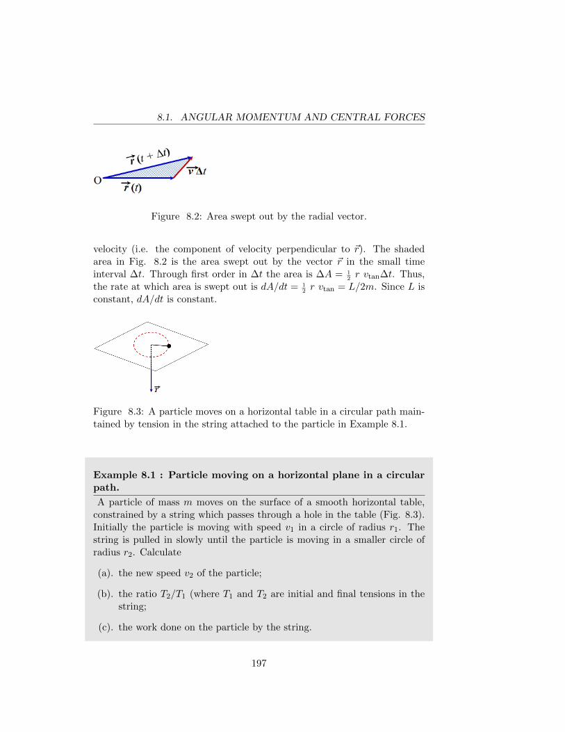
8.1. ANGULAR MOMENTUM AND CENTRAL FORCES
Figure 8.2: Area swept out by the radial vector.
velocity (i.e. the component of velocity perpendicular to ~r). The shadedarea in Fig. 8.2 is the area swept out by the vector ~r in the small timeinterval ∆t. Through first order in ∆t the area is ∆A = 1
2r vtan∆t. Thus,
the rate at which area is swept out is dA/dt = 12r vtan = L/2m. Since L is
constant, dA/dt is constant.
Figure 8.3: A particle moves on a horizontal table in a circular path main-tained by tension in the string attached to the particle in Example 8.1.
Example 8.1 : Particle moving on a horizontal plane in a circularpath.
A particle of mass m moves on the surface of a smooth horizontal table,constrained by a string which passes through a hole in the table (Fig. 8.3).Initially the particle is moving with speed v1 in a circle of radius r1. Thestring is pulled in slowly until the particle is moving in a smaller circle ofradius r2. Calculate
(a). the new speed v2 of the particle;
(b). the ratio T2/T1 (where T1 and T2 are initial and final tensions in thestring;
(c). the work done on the particle by the string.
197
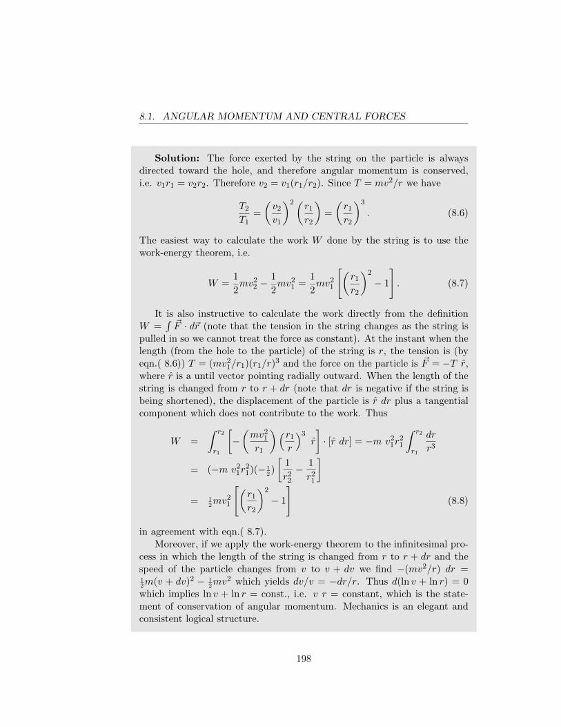
8.1. ANGULAR MOMENTUM AND CENTRAL FORCES
Solution: The force exerted by the string on the particle is alwaysdirected toward the hole, and therefore angular momentum is conserved,i.e. v1r1 = v2r2. Therefore v2 = v1(r1/r2). Since T = mv2/r we have
T2
T1=
(v2
v1
)2(r1
r2
)=
(r1
r2
)3
. (8.6)
The easiest way to calculate the work W done by the string is to use thework-energy theorem, i.e.
W =1
2mv2
2 −1
2mv2
1 =1
2mv2
1
[(r1
r2
)2
− 1
]. (8.7)
It is also instructive to calculate the work directly from the definitionW =
∫~F · d~r (note that the tension in the string changes as the string is
pulled in so we cannot treat the force as constant). At the instant when thelength (from the hole to the particle) of the string is r, the tension is (byeqn.( 8.6)) T = (mv2
1/r1)(r1/r)3 and the force on the particle is ~F = −T r,
where r is a until vector pointing radially outward. When the length of thestring is changed from r to r + dr (note that dr is negative if the string isbeing shortened), the displacement of the particle is r dr plus a tangentialcomponent which does not contribute to the work. Thus
W =
∫ r2
r1
[−(mv2
1
r1
)(r1
r
)3r
]· [r dr] = −m v2
1r21
∫ r2
r1
dr
r3
= (−m v21r
21)(− 1
2)
[1
r22
− 1
r21
]= 1
2mv2
1
[(r1
r2
)2
− 1
](8.8)
in agreement with eqn.( 8.7).Moreover, if we apply the work-energy theorem to the infinitesimal pro-
cess in which the length of the string is changed from r to r + dr and thespeed of the particle changes from v to v + dv we find −(mv2/r) dr =12m(v + dv)2 − 1
2mv2 which yields dv/v = −dr/r. Thus d(ln v + ln r) = 0
which implies ln v + ln r = const., i.e. v r = constant, which is the state-ment of conservation of angular momentum. Mechanics is an elegant andconsistent logical structure.
198
8.2. SYSTEMS OF MORE THAN ONE PARTICLE
8.2 Systems Of More Than One Particle
We now turn our attention to systems consisting of more than one particle(the index i enumerates the particles). Each particle obeys eqn.( 8.4), i.e.
~τi =d~Lidt
[~τ = ~ri × ~Fi, ~Li = mi~ri × ~vi]. (8.9)
If we add up the torque equations eqn.( 8.9) for all the particles in thesystem, the torques due to internal forces cancel out for reasons discussedin Chapter 7. Defining the total angular momentum of the system as thesum of the angular momenta of the individual particles
~L =∑i
mi~ri × ~vi (8.10)
we obtain
~τext =d~L
dt(8.11)
where ~τext is the total external torque acting on the system.In deriving eqn.( 8.11) it was assumed that ~ri and ~vi are the position
and velocity vectors of the i-th particle in an inertial frame . In fact eqn.(8.11) is also true if we use axes which are non-rotating (with respect to thedistant stars) and whose origin is the center of mass of the system1. Suchaxes are not an inertial frame if the center of mass is accelerating, but arefrequently the most convenient axes.
The force equation eqn.( 4.9) [~Fext = M ~ACM] and the torque equationeqn.( 8.11) completely determine the motion if the system is a rigid body.Our object here is to develop the techniques for solving simple problems,keeping the mathematics as simple as possible. Therefore we shall confineour attention mainly to the two-dimensional rigid body which moves alwaysin the plane of the page and has negligible thickness in the direction perpen-dicular to this plane. The analysis is also applicable to rigid bodies whichare not of negligible thickness, provided that all the motions of the body areparallel to a fixed plane and the body possesses sufficient symmetry2.
If we paint a line on a two-dimensional rigid body, the line will, in general,have a different position and direction at time t + ∆t than it did at timet. In Fig. 8.4 the solid and dotted curves represent the configuration ofthe body at time t and t + ∆t, respectively. Let the angle between the
1The proof is given in Appendix B2A full discussion of this point would take us too far afield. See Appendix B.
199
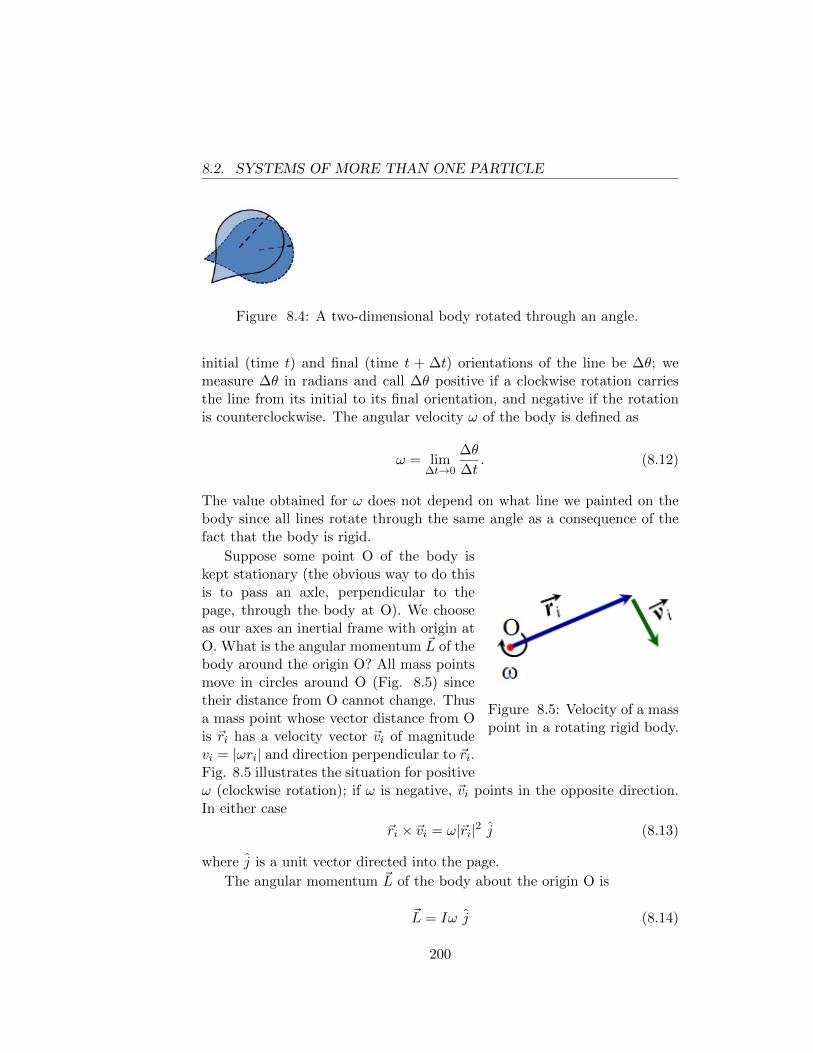
8.2. SYSTEMS OF MORE THAN ONE PARTICLE
Figure 8.4: A two-dimensional body rotated through an angle.
initial (time t) and final (time t + ∆t) orientations of the line be ∆θ; wemeasure ∆θ in radians and call ∆θ positive if a clockwise rotation carriesthe line from its initial to its final orientation, and negative if the rotationis counterclockwise. The angular velocity ω of the body is defined as
ω = lim∆t→0
∆θ
∆t. (8.12)
The value obtained for ω does not depend on what line we painted on thebody since all lines rotate through the same angle as a consequence of thefact that the body is rigid.
Figure 8.5: Velocity of a masspoint in a rotating rigid body.
Suppose some point O of the body iskept stationary (the obvious way to do thisis to pass an axle, perpendicular to thepage, through the body at O). We chooseas our axes an inertial frame with origin atO. What is the angular momentum ~L of thebody around the origin O? All mass pointsmove in circles around O (Fig. 8.5) sincetheir distance from O cannot change. Thusa mass point whose vector distance from Ois ~ri has a velocity vector ~vi of magnitudevi = |ωri| and direction perpendicular to ~ri.Fig. 8.5 illustrates the situation for positiveω (clockwise rotation); if ω is negative, ~vi points in the opposite direction.In either case
~ri × ~vi = ω|~ri|2 j (8.13)
where j is a unit vector directed into the page.
The angular momentum ~L of the body about the origin O is
~L = Iω j (8.14)
200
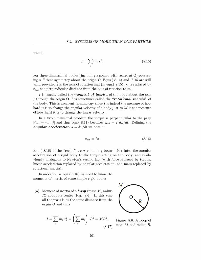
8.2. SYSTEMS OF MORE THAN ONE PARTICLE
where
I =∑i
mi r2i . (8.15)
For three-dimensional bodies (including a sphere with center at O) possess-ing sufficient symmetry about the origin O, Eqns.( 8.14) and 8.15 are stillvalid provided j is the axis of rotation and (in eqn.( 8.15)) ri is replaced byri⊥, the perpendicular distance from the axis of rotation to mi.
I is usually called the moment of inertia of the body about the axisj through the origin O. I is sometimes called the “rotational inertia” ofthe body. This is excellent terminology since I is indeed the measure of howhard it is to change the angular velocity of a body just as M is the measureof how hard it is to change the linear velocity.
In a two-dimensional problem the torque is perpendicular to the page[~τext = τext j] and thus eqn.( 8.11) becomes τext = I dω/dt. Defining theangular acceleration α = dω/dt we obtain
τext = Iα (8.16)
Eqn.( 8.16) is the “recipe” we were aiming toward; it relates the angularacceleration of a rigid body to the torque acting on the body, and is ob-viously analogous to Newton’s second law (with force replaced by torque,linear acceleration replaced by angular acceleration, and mass replaced byrotational inertia).
Figure 8.6: A hoop ofmass M and radius R.
In order to use eqn.( 8.16) we need to know themoments of inertia of some simple rigid bodies:
(a). Moment of inertia of a hoop (mass M , radiusR) about its center (Fig. 8.6). In this caseall the mass is at the same distance from theorigin O and thus
I =∑i
mi r2i =
(∑i
mi
)R2 = MR2.
(8.17)
201
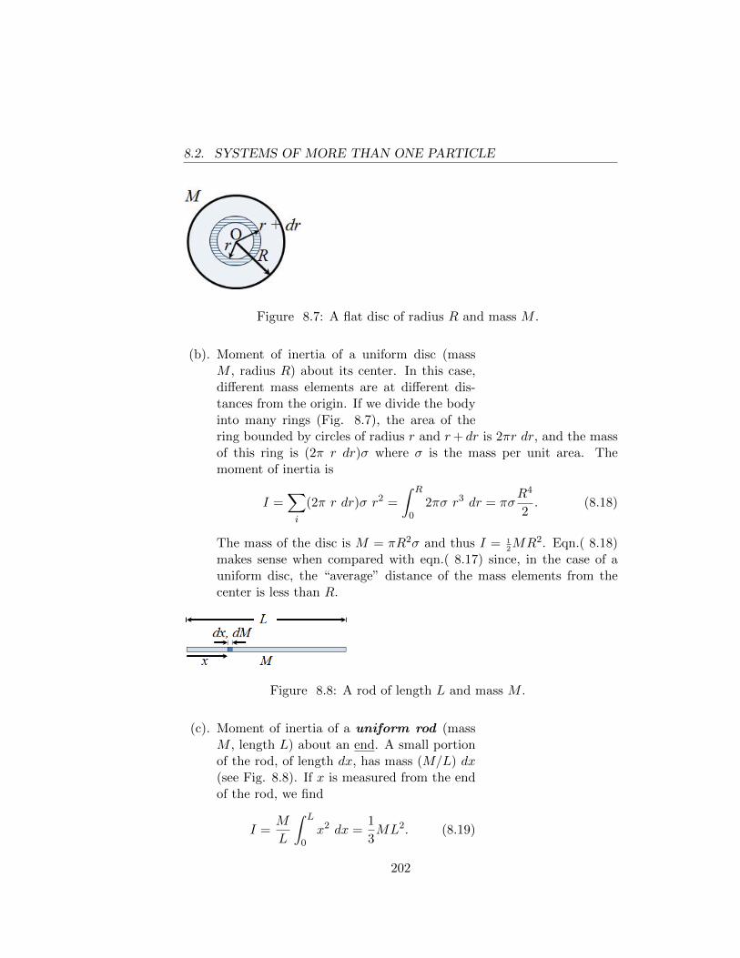
8.2. SYSTEMS OF MORE THAN ONE PARTICLE
Figure 8.7: A flat disc of radius R and mass M .
(b). Moment of inertia of a uniform disc (massM , radius R) about its center. In this case,different mass elements are at different dis-tances from the origin. If we divide the bodyinto many rings (Fig. 8.7), the area of thering bounded by circles of radius r and r+ dr is 2πr dr, and the massof this ring is (2π r dr)σ where σ is the mass per unit area. Themoment of inertia is
I =∑i
(2π r dr)σ r2 =
∫ R
02πσ r3 dr = πσ
R4
2. (8.18)
The mass of the disc is M = πR2σ and thus I = 12MR2. Eqn.( 8.18)
makes sense when compared with eqn.( 8.17) since, in the case of auniform disc, the “average” distance of the mass elements from thecenter is less than R.
Figure 8.8: A rod of length L and mass M .
(c). Moment of inertia of a uniform rod (massM , length L) about an end. A small portionof the rod, of length dx, has mass (M/L) dx(see Fig. 8.8). If x is measured from the endof the rod, we find
I =M
L
∫ L
0x2 dx =
1
3ML2. (8.19)
202
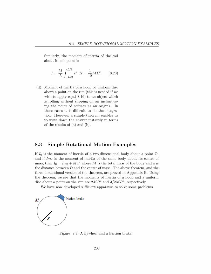
8.3. SIMPLE ROTATIONAL MOTION EXAMPLES
Similarly, the moment of inertia of the rodabout its midpoint is
I =M
L
∫ L/2
−L/2x2 dx =
1
12ML2. (8.20)
(d). Moment of inertia of a hoop or uniform discabout a point on the rim (this is needed if wewish to apply eqn.( 8.16) to an object whichis rolling without slipping on an incline us-ing the point of contact as an origin). Inthese cases it is difficult to do the integra-tion. However, a simple theorem enables usto write down the answer instantly in termsof the results of (a) and (b).
8.3 Simple Rotational Motion Examples
If I0 is the moment of inertia of a two-dimensional body about a point O,and if ICM is the moment of inertia of the same body about its center ofmass, then I0 = ICM +Ma2 where M is the total mass of the body and a isthe distance between O and the center of mass. The above theorem, and thethree-dimensional version of the theorem, are proved in Appendix B. Usingthe theorem, we see that the moments of inertia of a hoop and a uniformdisc about a point on the rim are 2MR2 and 3/2MR2, respectively.
We have now developed sufficient apparatus to solve some problems.
Figure 8.9: A flywheel and a friction brake.
203
8.3. SIMPLE ROTATIONAL MOTION EXAMPLES
Example 8.2 : A flywheel with a friction brake.
A flywheel is a uniform disc of mass 100 kg and radius 0.50 m and isinitially rotating at the rate of 20.0 revolutions per second. A friction brakeis applied to the rim and exerts a tangential braking force of 20.0 newtons.Calculate
(a). the time required for the wheel to stop, and
(b). the number of revolutions it makes from the instant the brake is applieduntil it stops.
Solution: First we shall solve the problem with symbols. For conve-nience we assume that the wheel is spinning clockwise. The tangential com-ponent F of the braking force is directed counterclockwise (note that theradial component of the force exerted by the brake produces no torque aboutthe center of the wheel). The brake produces a counterclockwise torque ofmagnitude F R (R = radius). From eqn.( 8.16) we have −F R = 1
2MR2α
and thus α = −2 F/MR. If the number of revolutions per second is initiallyn0, the initial angular velocity is ω0 = 2πn0.
Now we note that The kinetic formulas derived in Chapter 1 to describeone-dimensional motion with constant acceleration apply equally well to ro-tational motion with constant angular acceleration, with appropriate changeof symbols (x → θ, v → ω, a → α). The derivations are identical withthose of Chapter 1. Thus we have
θ = θ0 + ω0t+ 12αt2 (8.21)
ω = ω0 + αt (8.22)
ω2 = ω20 + 2α(θ − θ0) (8.23)
θ − θ0 = 12(ω0 + ω)t (8.24)
We define θ as positive in the clockwise sense, consistently with our conven-tion that ω is positive for clockwise rotation.
The time T required to stop the wheel is found from eqn.( 8.22); settingω = 0, we find T = −ω0/α = MRω0/(2F ). The angle θ through whichthe wheel turns while stopping is found most easily from eqn.( 8.24), whichyields θ = 1
2ω0T = (1/4)MRω2
0/F . The number of revolutions the wheelmakes while stopping is θ/2π. Inserting numbers, we find α = −0.800rad/s2, ω0 = 40.0π rad/s, T = 157 s, number of revs = 1570.
204
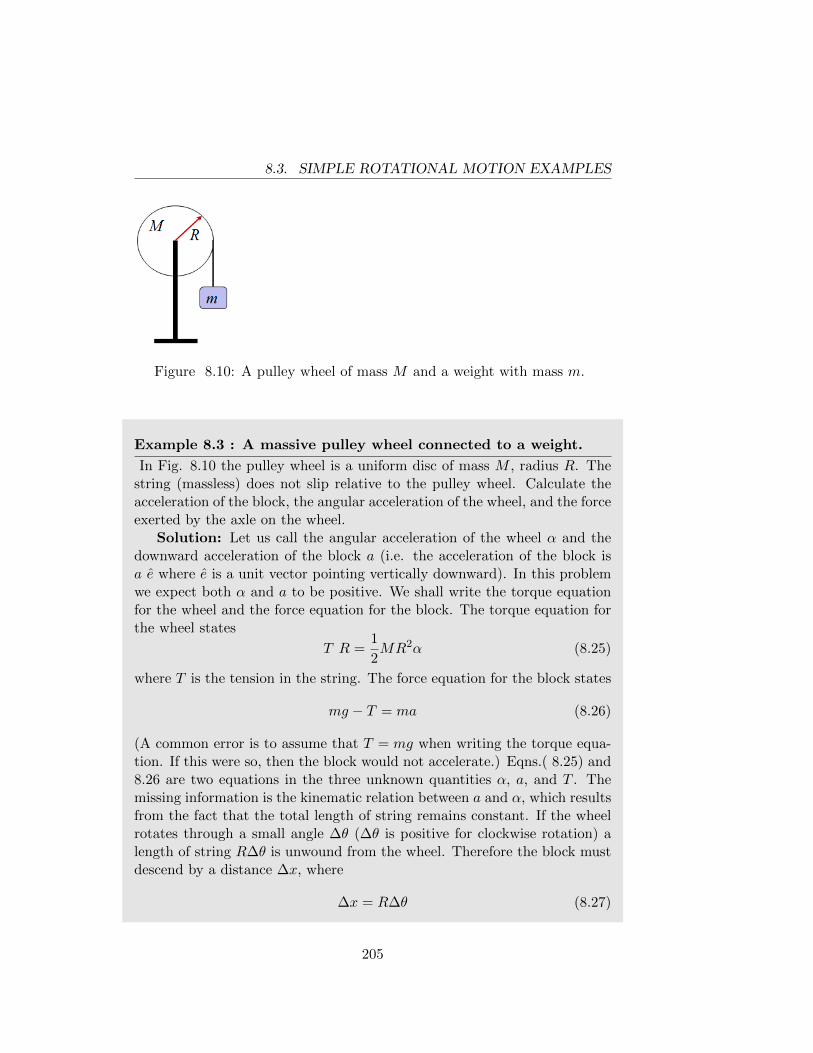
8.3. SIMPLE ROTATIONAL MOTION EXAMPLES
Figure 8.10: A pulley wheel of mass M and a weight with mass m.
Example 8.3 : A massive pulley wheel connected to a weight.
In Fig. 8.10 the pulley wheel is a uniform disc of mass M , radius R. Thestring (massless) does not slip relative to the pulley wheel. Calculate theacceleration of the block, the angular acceleration of the wheel, and the forceexerted by the axle on the wheel.
Solution: Let us call the angular acceleration of the wheel α and thedownward acceleration of the block a (i.e. the acceleration of the block isa e where e is a unit vector pointing vertically downward). In this problemwe expect both α and a to be positive. We shall write the torque equationfor the wheel and the force equation for the block. The torque equation forthe wheel states
T R =1
2MR2α (8.25)
where T is the tension in the string. The force equation for the block states
mg − T = ma (8.26)
(A common error is to assume that T = mg when writing the torque equa-tion. If this were so, then the block would not accelerate.) Eqns.( 8.25) and8.26 are two equations in the three unknown quantities α, a, and T . Themissing information is the kinematic relation between a and α, which resultsfrom the fact that the total length of string remains constant. If the wheelrotates through a small angle ∆θ (∆θ is positive for clockwise rotation) alength of string R∆θ is unwound from the wheel. Therefore the block mustdescend by a distance ∆x, where
∆x = R∆θ (8.27)
205
8.3. SIMPLE ROTATIONAL MOTION EXAMPLES
Dividing both sides of eqn.( 8.27) by ∆t and letting ∆t→ 0, we find
dx
dt= R
dθ
dt= Rω (8.28)
and differentiating eqn.( 8.28) with respect to t we find
a =d2x
dt2= Rα. (8.29)
Inserting eqn.( 8.29) into eqn.( 8.25) we obtain T = 12Ma and thus, from
eqn.( 8.26),
a =g
1 +M/2m= Rα.
To find the force exerted by the axle on the wheel, we take as our systemthe wheel plus a slightly greater length of string than is wound around thewheel (see Fig. 8.11). The center of mass of this system is permanentlyat rest and therefore the force on the system vanishes. The forces on thesystem are ~T (acting downward), M~g (acting downward), and an upwardforce ~F exerted by the axle. Since F − T −Mg = 0 we find
F = T +Mg = Mg3 +M/m
2 +M/m.
We can also find F by applying eqn.( 3.6) [~Fext =∑
imi~ai] to the system(wheel + block + string), obtaining F − (M +m)g = −ma. This yields thesame value of F as the preceding method.
206
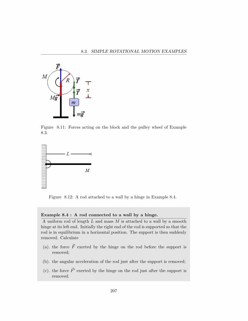
8.3. SIMPLE ROTATIONAL MOTION EXAMPLES
Figure 8.11: Forces acting on the block and the pulley wheel of Example8.3.
Figure 8.12: A rod attached to a wall by a hinge in Example 8.4.
Example 8.4 : A rod connected to a wall by a hinge.
A uniform rod of length L and mass M is attached to a wall by a smoothhinge at its left end. Initially the right end of the rod is supported so that therod is in equilibrium in a horizontal position. The support is then suddenlyremoved. Calculate
(a). the force ~F exerted by the hinge on the rod before the support isremoved;
(b). the angular acceleration of the rod just after the support is removed;
(c). the force ~F ′ exerted by the hinge on the rod just after the support isremoved.
207
8.3. SIMPLE ROTATIONAL MOTION EXAMPLES
Solution: Part (a) is a problem in static equilibrium. Taking torquesaround the right end of the rod, we have FL −MgL/2 = 0 → F = Mg/2.In equilibrium, a force of Mg/2 must also be exerted on the right end. Afterthe rod is released, we will take torques about an origin at the hinge (thus,the force exerted by the hinge will not appear in the torque equation). Theonly torque is produced by gravity (acting at the CM), and we obtain justafter the support is removed Mg L/2 = 1/3ML2α and thus α = 3/2g/L.Since the right end moves in a circle of radius L, its tangential (vertical)acceleration is Lα, i.e. 3/2g. The fact that the right end has a verticalacceleration larger than g can be verifed by a simple demonstration (Fig.8.13). If a meter stick is arranged so that one end is supported by a tableor hinged to a wall so that the meter stick can swing freely in the verticaldirection, then a line of pennies placed along the top of the meter stickwhile it is held horizontal will show the effect of the end of the meter stickfalling with acceleration greater than gravitational acceleration. The imageclearly shows the line of pennies “leaving” the stick as it swings downward.Similarly, if several persons are sitting on a toboggan which goes over abump, the sled will fall way from the front person unless he/she holds on toa handle.
To find the force exerted by the hinge just after the support is removed,we apply the force equation [~Fext = M ~ACM] to the rod at this moment. Theacceleration of the CM is 1
2Lα, or 3/4 g vertically downward. The forces
acting on the rod are Mg (downward) and the upward force F ′ exerted bythe hinge. Thus F ′−Mg = M(−3g/4) and hence F ′ = Mg/4. Note that theforce exerted by the hinge changes its value (from Mg/2 to Mg/4) suddenlyat the instant of release.
The force ~F ′ can also be obtained by writing the torque equation, usingthe center of mass as the origin (recall that eqn.( 8.11) is also valid in thiscase). Eqn.( 8.2) can be used to calculate the angular momentum of a rigidbody about its CM, provided we use ICM as the moment of inertia. Notethat when we write the torque equation about the CM, gravity produces notorque since it may be considered to act at the CM; however, the verticalforce F ′ exerted by the hinge produces a clockwise torque F ′ L/2. Thus thetorque equation about the CM is
F ′L
2=
1
12ML2α.
Inserting α = 3/2 g/L we obtain F ′ = 1/4 Mg in agreement with theprevious calculation.
208
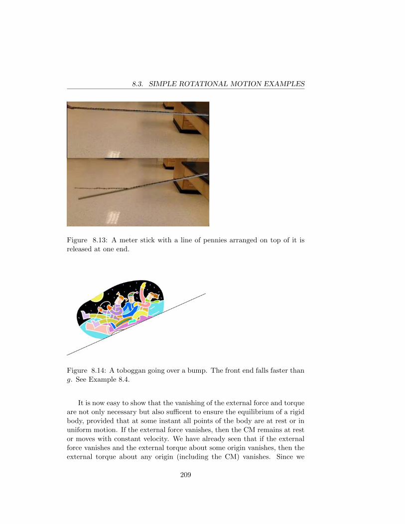
8.3. SIMPLE ROTATIONAL MOTION EXAMPLES
Figure 8.13: A meter stick with a line of pennies arranged on top of it isreleased at one end.
Figure 8.14: A toboggan going over a bump. The front end falls faster thang. See Example 8.4.
It is now easy to show that the vanishing of the external force and torqueare not only necessary but also sufficent to ensure the equilibrium of a rigidbody, provided that at some instant all points of the body are at rest or inuniform motion. If the external force vanishes, then the CM remains at restor moves with constant velocity. We have already seen that if the externalforce vanishes and the external torque about some origin vanishes, then theexternal torque about any origin (including the CM) vanishes. Since we
209
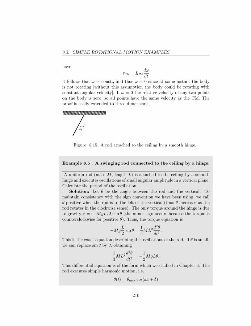
8.3. SIMPLE ROTATIONAL MOTION EXAMPLES
have
τCM = ICMdω
dtit follows that ω = const., and thus ω = 0 since at some instant the bodyis not rotating [without this assumption the body could be rotating withconstant angular velocity]. If ω = 0 the relative velocity of any two pointson the body is zero, so all points have the same velocity as the CM. Theproof is easily extended to three dimensions.
Figure 8.15: A rod attached to the ceiling by a smooth hinge.
Example 8.5 : A swinging rod connected to the ceiling by a hinge.
A uniform rod (mass M , length L) is attached to the ceiling by a smoothhinge and executes oscillations of small angular amplitude in a vertical plane.Calculate the period of the oscillation.
Solution: Let θ be the angle between the rod and the vertical. Tomaintain consistency with the sign convention we have been using, we callθ positive when the rod is to the left of the vertical (thus θ increases as therod rotates in the clockwise sense). The only torque around the hinge is dueto gravity τ = (−MgL/2) sin θ (the minus sign occurs because the torque iscounterclockwise for positive θ). Thus, the torque equation is
−MgL
2sin θ =
1
3ML2d
2θ
dt2.
This is the exact equation describing the oscillations of the rod. If θ is small,we can replace sin θ by θ, obtaining
1
3ML2d
2θ
dt2= −1
2MgLθ.
This differential equation is of the form which we studied in Chapter 6. Therod executes simple harmonic motion, i.e.
θ(t) = θmax cos(ωt+ δ)
210
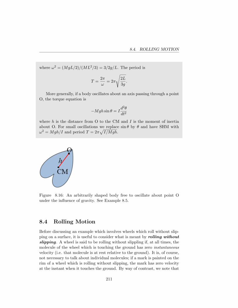
8.4. ROLLING MOTION
where ω2 = (MgL/2)/(ML2/3) = 3/2g/L. The period is
T =2π
ω= 2π
√2L
3g.
More generally, if a body oscillates about an axis passing through a pointO, the torque equation is
−Mgh sin θ = Id2θ
dt2
where h is the distance from O to the CM and I is the moment of inertiaabout O. For small oscillations we replace sin θ by θ and have SHM withω2 = Mgh/I and period T = 2π
√I/Mgh.
Figure 8.16: An arbitrarily shaped body free to oscillate about point Ounder the influence of gravity. See Example 8.5.
8.4 Rolling Motion
Before discussing an example which involves wheels which roll without slip-ping on a surface, it is useful to consider what is meant by rolling withoutslipping . A wheel is said to be rolling without slippling if, at all times, themolecule of the wheel which is touching the ground has zero instantaneousvelocity (i.e. that molecule is at rest relative to the ground). It is, of course,not necessary to talk about individual molecules; if a mark is painted on therim of a wheel which is rolling without slipping, the mark has zero velocityat the instant when it touches the ground. By way of contrast, we note that
211
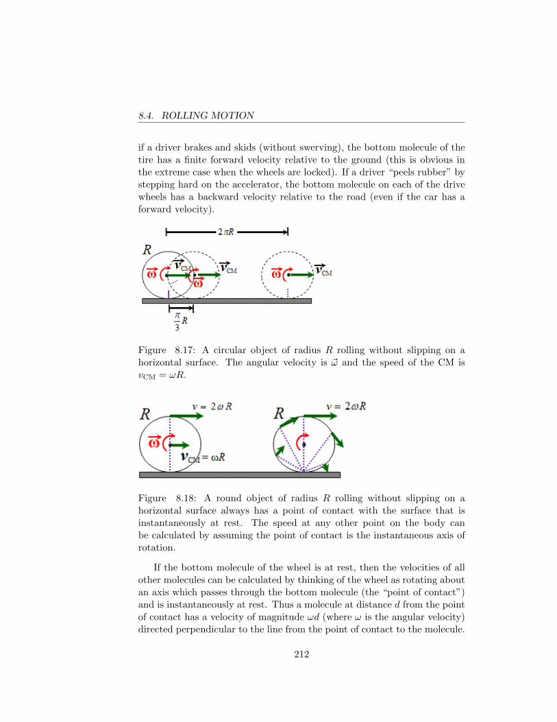
8.4. ROLLING MOTION
if a driver brakes and skids (without swerving), the bottom molecule of thetire has a finite forward velocity relative to the ground (this is obvious inthe extreme case when the wheels are locked). If a driver “peels rubber” bystepping hard on the accelerator, the bottom molecule on each of the drivewheels has a backward velocity relative to the road (even if the car has aforward velocity).
Figure 8.17: A circular object of radius R rolling without slipping on ahorizontal surface. The angular velocity is ~ω and the speed of the CM isvCM = ωR.
Figure 8.18: A round object of radius R rolling without slipping on ahorizontal surface always has a point of contact with the surface that isinstantaneously at rest. The speed at any other point on the body canbe calculated by assuming the point of contact is the instantaneous axis ofrotation.
If the bottom molecule of the wheel is at rest, then the velocities of allother molecules can be calculated by thinking of the wheel as rotating aboutan axis which passes through the bottom molecule (the “point of contact”)and is instantaneously at rest. Thus a molecule at distance d from the pointof contact has a velocity of magnitude ωd (where ω is the angular velocity)directed perpendicular to the line from the point of contact to the molecule.
212
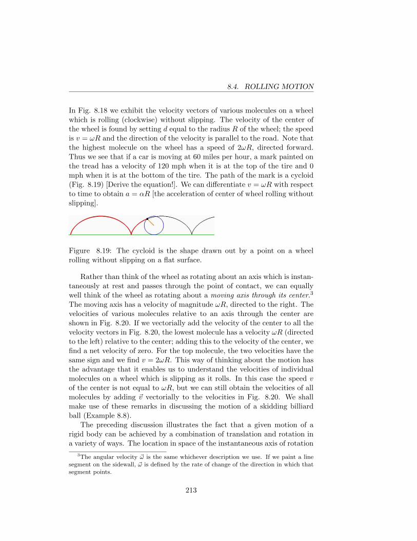
8.4. ROLLING MOTION
In Fig. 8.18 we exhibit the velocity vectors of various molecules on a wheelwhich is rolling (clockwise) without slipping. The velocity of the center ofthe wheel is found by setting d equal to the radius R of the wheel; the speedis v = ωR and the direction of the velocity is parallel to the road. Note thatthe highest molecule on the wheel has a speed of 2ωR, directed forward.Thus we see that if a car is moving at 60 miles per hour, a mark painted onthe tread has a velocity of 120 mph when it is at the top of the tire and 0mph when it is at the bottom of the tire. The path of the mark is a cycloid(Fig. 8.19) [Derive the equation!]. We can differentiate v = ωR with respectto time to obtain a = αR [the acceleration of center of wheel rolling withoutslipping].
Figure 8.19: The cycloid is the shape drawn out by a point on a wheelrolling without slipping on a flat surface.
Rather than think of the wheel as rotating about an axis which is instan-taneously at rest and passes through the point of contact, we can equallywell think of the wheel as rotating about a moving axis through its center.3
The moving axis has a velocity of magnitude ωR, directed to the right. Thevelocities of various molecules relative to an axis through the center areshown in Fig. 8.20. If we vectorially add the velocity of the center to all thevelocity vectors in Fig. 8.20, the lowest molecule has a velocity ωR (directedto the left) relative to the center; adding this to the velocity of the center, wefind a net velocity of zero. For the top molecule, the two velocities have thesame sign and we find v = 2ωR. This way of thinking about the motion hasthe advantage that it enables us to understand the velocities of individualmolecules on a wheel which is slipping as it rolls. In this case the speed vof the center is not equal to ωR, but we can still obtain the velocities of allmolecules by adding ~v vectorially to the velocities in Fig. 8.20. We shallmake use of these remarks in discussing the motion of a skidding billiardball (Example 8.8).
The preceding discussion illustrates the fact that a given motion of arigid body can be achieved by a combination of translation and rotation ina variety of ways. The location in space of the instantaneous axis of rotation
3The angular velocity ~ω is the same whichever description we use. If we paint a linesegment on the sidewall, ~ω is defined by the rate of change of the direction in which thatsegment points.
213
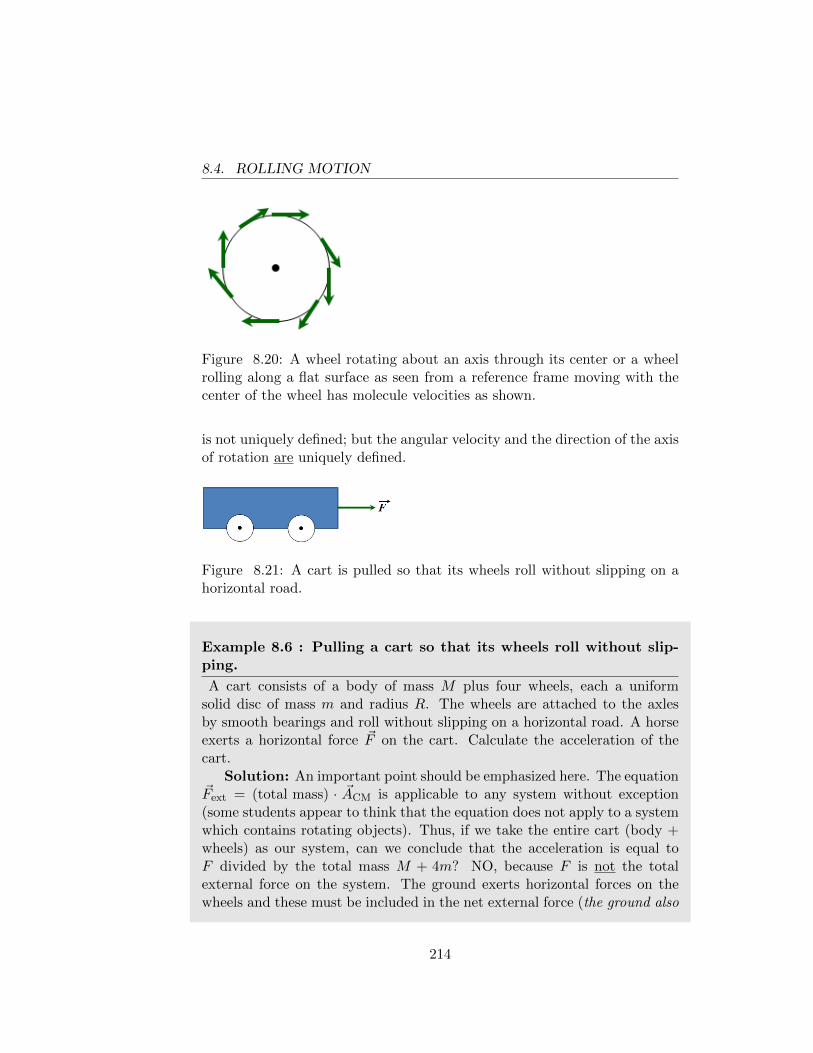
8.4. ROLLING MOTION
Figure 8.20: A wheel rotating about an axis through its center or a wheelrolling along a flat surface as seen from a reference frame moving with thecenter of the wheel has molecule velocities as shown.
is not uniquely defined; but the angular velocity and the direction of the axisof rotation are uniquely defined.
Figure 8.21: A cart is pulled so that its wheels roll without slipping on ahorizontal road.
Example 8.6 : Pulling a cart so that its wheels roll without slip-ping.
A cart consists of a body of mass M plus four wheels, each a uniformsolid disc of mass m and radius R. The wheels are attached to the axlesby smooth bearings and roll without slipping on a horizontal road. A horseexerts a horizontal force ~F on the cart. Calculate the acceleration of thecart.
Solution: An important point should be emphasized here. The equation~Fext = (total mass) · ~ACM is applicable to any system without exception(some students appear to think that the equation does not apply to a systemwhich contains rotating objects). Thus, if we take the entire cart (body +wheels) as our system, can we conclude that the acceleration is equal toF divided by the total mass M + 4m? NO, because F is not the totalexternal force on the system. The ground exerts horizontal forces on thewheels and these must be included in the net external force (the ground also
214
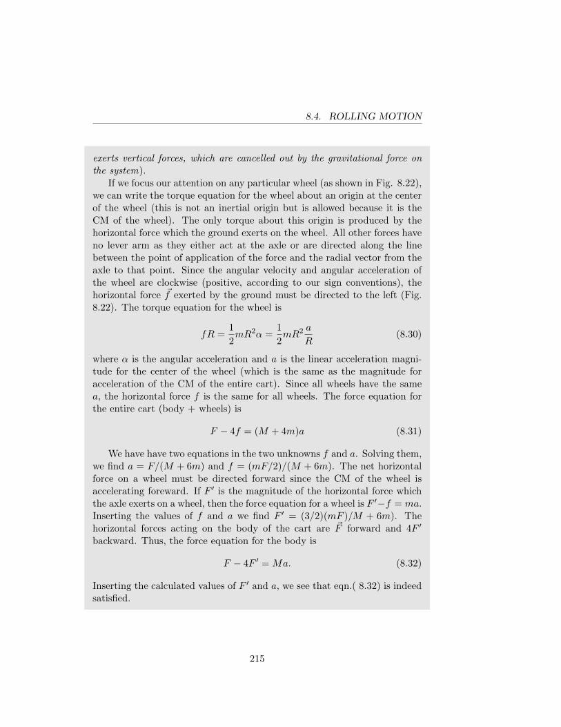
8.4. ROLLING MOTION
exerts vertical forces, which are cancelled out by the gravitational force onthe system).
If we focus our attention on any particular wheel (as shown in Fig. 8.22),we can write the torque equation for the wheel about an origin at the centerof the wheel (this is not an inertial origin but is allowed because it is theCM of the wheel). The only torque about this origin is produced by thehorizontal force which the ground exerts on the wheel. All other forces haveno lever arm as they either act at the axle or are directed along the linebetween the point of application of the force and the radial vector from theaxle to that point. Since the angular velocity and angular acceleration ofthe wheel are clockwise (positive, according to our sign conventions), thehorizontal force ~f exerted by the ground must be directed to the left (Fig.8.22). The torque equation for the wheel is
fR =1
2mR2α =
1
2mR2 a
R(8.30)
where α is the angular acceleration and a is the linear acceleration magni-tude for the center of the wheel (which is the same as the magnitude foracceleration of the CM of the entire cart). Since all wheels have the samea, the horizontal force f is the same for all wheels. The force equation forthe entire cart (body + wheels) is
F − 4f = (M + 4m)a (8.31)
We have have two equations in the two unknowns f and a. Solving them,we find a = F/(M + 6m) and f = (mF/2)/(M + 6m). The net horizontalforce on a wheel must be directed forward since the CM of the wheel isaccelerating foreward. If F ′ is the magnitude of the horizontal force whichthe axle exerts on a wheel, then the force equation for a wheel is F ′−f = ma.Inserting the values of f and a we find F ′ = (3/2)(mF )/M + 6m). Thehorizontal forces acting on the body of the cart are ~F forward and 4F ′
backward. Thus, the force equation for the body is
F − 4F ′ = Ma. (8.32)
Inserting the calculated values of F ′ and a, we see that eqn.( 8.32) is indeedsatisfied.
215
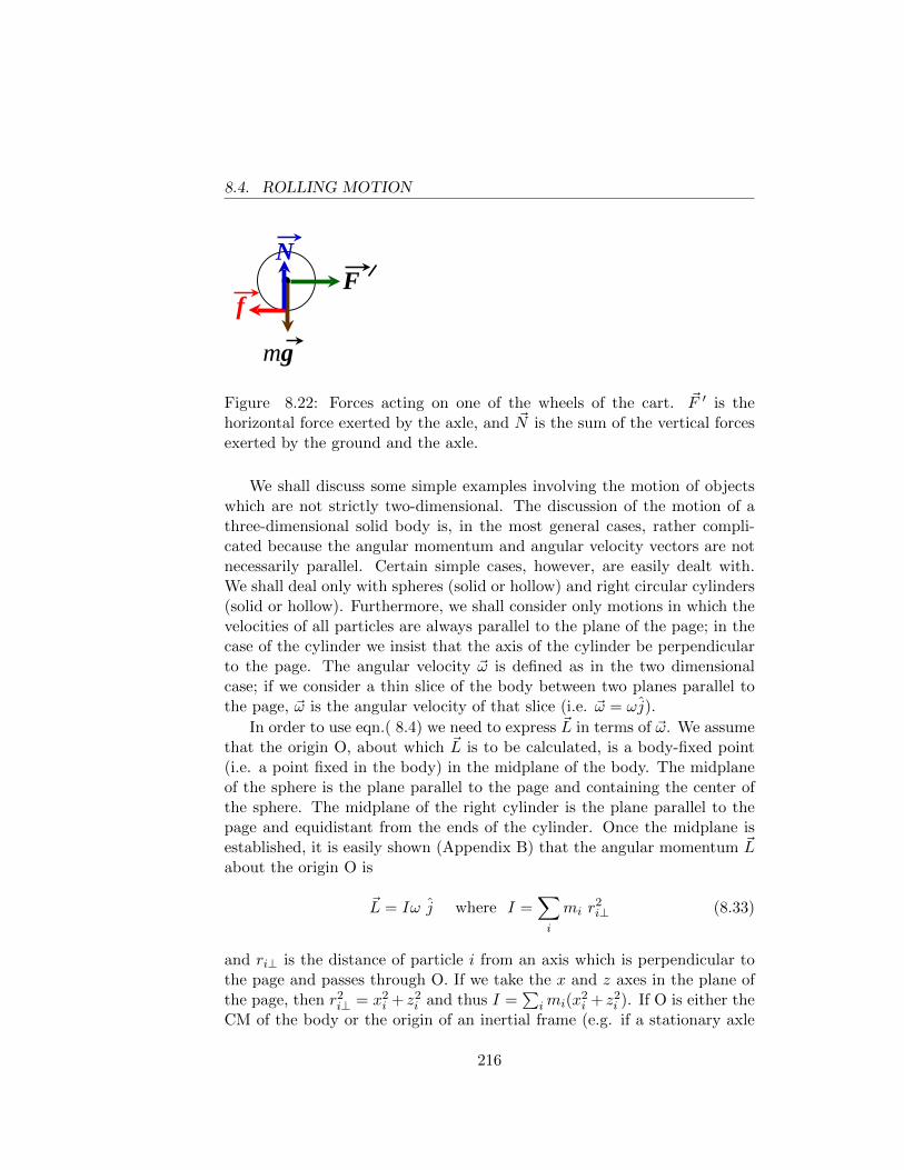
8.4. ROLLING MOTION
F f
mg
N
Figure 8.22: Forces acting on one of the wheels of the cart. ~F ′ is thehorizontal force exerted by the axle, and ~N is the sum of the vertical forcesexerted by the ground and the axle.
We shall discuss some simple examples involving the motion of objectswhich are not strictly two-dimensional. The discussion of the motion of athree-dimensional solid body is, in the most general cases, rather compli-cated because the angular momentum and angular velocity vectors are notnecessarily parallel. Certain simple cases, however, are easily dealt with.We shall deal only with spheres (solid or hollow) and right circular cylinders(solid or hollow). Furthermore, we shall consider only motions in which thevelocities of all particles are always parallel to the plane of the page; in thecase of the cylinder we insist that the axis of the cylinder be perpendicularto the page. The angular velocity ~ω is defined as in the two dimensionalcase; if we consider a thin slice of the body between two planes parallel tothe page, ~ω is the angular velocity of that slice (i.e. ~ω = ωj).
In order to use eqn.( 8.4) we need to express ~L in terms of ~ω. We assumethat the origin O, about which ~L is to be calculated, is a body-fixed point(i.e. a point fixed in the body) in the midplane of the body. The midplaneof the sphere is the plane parallel to the page and containing the center ofthe sphere. The midplane of the right cylinder is the plane parallel to thepage and equidistant from the ends of the cylinder. Once the midplane isestablished, it is easily shown (Appendix B) that the angular momentum ~Labout the origin O is
~L = Iω j where I =∑i
mi r2i⊥ (8.33)
and ri⊥ is the distance of particle i from an axis which is perpendicular tothe page and passes through O. If we take the x and z axes in the plane ofthe page, then r2
i⊥ = x2i + z2
i and thus I =∑
imi(x2i + z2
i ). If O is either theCM of the body or the origin of an inertial frame (e.g. if a stationary axle
216
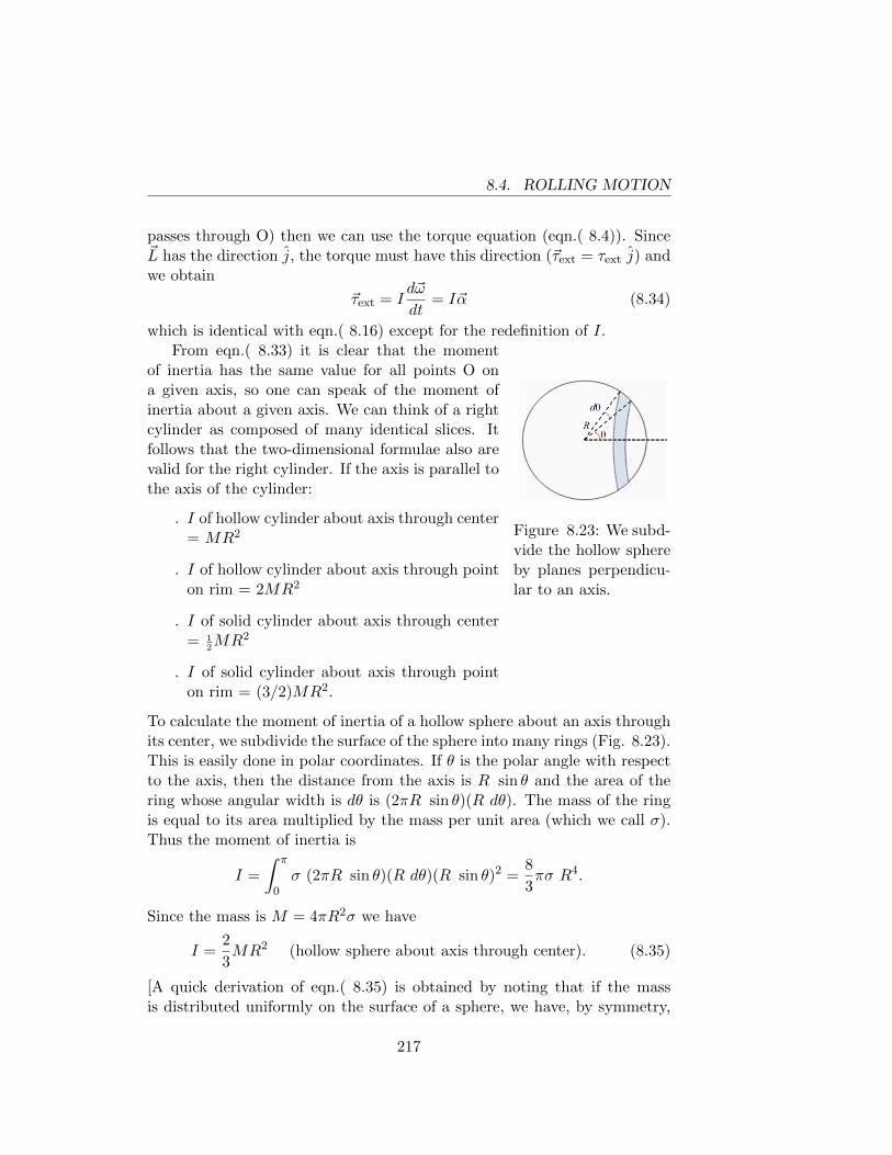
8.4. ROLLING MOTION
passes through O) then we can use the torque equation (eqn.( 8.4)). Since~L has the direction j, the torque must have this direction (~τext = τext j) andwe obtain
~τext = Id~ω
dt= I~α (8.34)
which is identical with eqn.( 8.16) except for the redefinition of I.
Figure 8.23: We subd-vide the hollow sphereby planes perpendicu-lar to an axis.
From eqn.( 8.33) it is clear that the momentof inertia has the same value for all points O ona given axis, so one can speak of the moment ofinertia about a given axis. We can think of a rightcylinder as composed of many identical slices. Itfollows that the two-dimensional formulae also arevalid for the right cylinder. If the axis is parallel tothe axis of the cylinder:
. I of hollow cylinder about axis through center= MR2
. I of hollow cylinder about axis through pointon rim = 2MR2
. I of solid cylinder about axis through center= 1
2MR2
. I of solid cylinder about axis through pointon rim = (3/2)MR2.
To calculate the moment of inertia of a hollow sphere about an axis throughits center, we subdivide the surface of the sphere into many rings (Fig. 8.23).This is easily done in polar coordinates. If θ is the polar angle with respectto the axis, then the distance from the axis is R sin θ and the area of thering whose angular width is dθ is (2πR sin θ)(R dθ). The mass of the ringis equal to its area multiplied by the mass per unit area (which we call σ).Thus the moment of inertia is
I =
∫ π
0σ (2πR sin θ)(R dθ)(R sin θ)2 =
8
3πσ R4.
Since the mass is M = 4πR2σ we have
I =2
3MR2 (hollow sphere about axis through center). (8.35)
[A quick derivation of eqn.( 8.35) is obtained by noting that if the massis distributed uniformly on the surface of a sphere, we have, by symmetry,
217
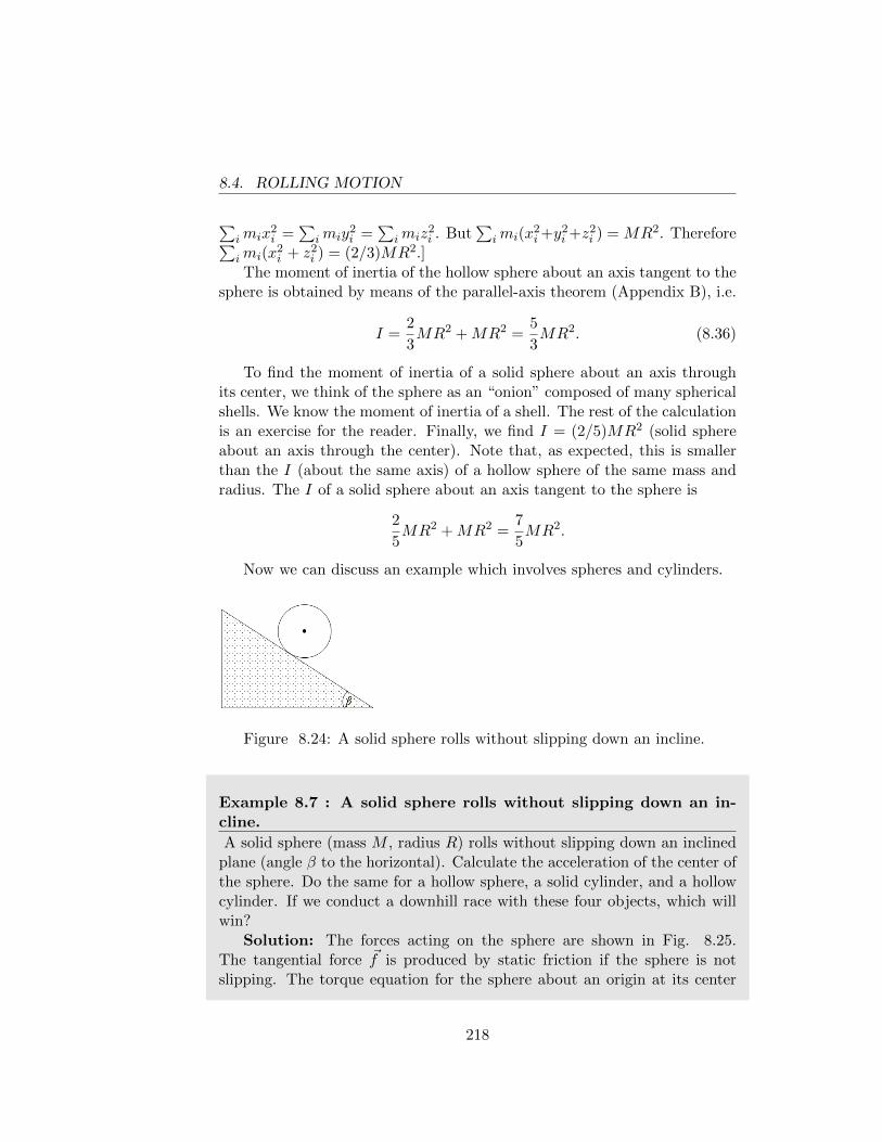
8.4. ROLLING MOTION
∑imix
2i =
∑imiy
2i =
∑imiz
2i . But
∑imi(x
2i+y
2i +z2
i ) = MR2. Therefore∑imi(x
2i + z2
i ) = (2/3)MR2.]The moment of inertia of the hollow sphere about an axis tangent to the
sphere is obtained by means of the parallel-axis theorem (Appendix B), i.e.
I =2
3MR2 +MR2 =
5
3MR2. (8.36)
To find the moment of inertia of a solid sphere about an axis throughits center, we think of the sphere as an “onion” composed of many sphericalshells. We know the moment of inertia of a shell. The rest of the calculationis an exercise for the reader. Finally, we find I = (2/5)MR2 (solid sphereabout an axis through the center). Note that, as expected, this is smallerthan the I (about the same axis) of a hollow sphere of the same mass andradius. The I of a solid sphere about an axis tangent to the sphere is
2
5MR2 +MR2 =
7
5MR2.
Now we can discuss an example which involves spheres and cylinders.
Figure 8.24: A solid sphere rolls without slipping down an incline.
Example 8.7 : A solid sphere rolls without slipping down an in-cline.
A solid sphere (mass M , radius R) rolls without slipping down an inclinedplane (angle β to the horizontal). Calculate the acceleration of the center ofthe sphere. Do the same for a hollow sphere, a solid cylinder, and a hollowcylinder. If we conduct a downhill race with these four objects, which willwin?
Solution: The forces acting on the sphere are shown in Fig. 8.25.The tangential force ~f is produced by static friction if the sphere is notslipping. The torque equation for the sphere about an origin at its center
218
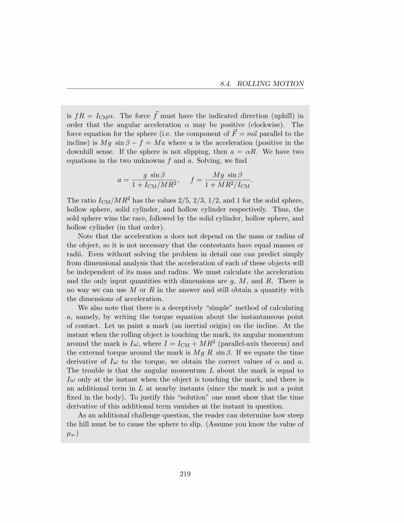
8.4. ROLLING MOTION
is fR = ICMα. The force ~f must have the indicated direction (uphill) inorder that the angular acceleration α may be positive (clockwise). Theforce equation for the sphere (i.e. the component of ~F = m~a parallel to theincline) is Mg sinβ − f = Ma where a is the acceleration (positive in thedownhill sense. If the sphere is not slipping, then a = αR. We have twoequations in the two unknowns f and a. Solving, we find
a =g sinβ
1 + ICM/MR2, f =
Mg sinβ
1 +MR2/ICM.
The ratio ICM/MR2 has the values 2/5, 2/3, 1/2, and 1 for the solid sphere,hollow sphere, solid cylinder, and hollow cylinder respectively. Thus, thesold sphere wins the race, followed by the solid cylinder, hollow sphere, andhollow cylinder (in that order).
Note that the acceleration a does not depend on the mass or radius ofthe object, so it is not necessary that the contestants have equal masses orradii. Even without solving the problem in detail one can predict simplyfrom dimensional analysis that the acceleration of each of these objects willbe independent of its mass and radius. We must calculate the accelerationand the only input quantities with dimensions are g, M , and R. There isno way we can use M or R in the answer and still obtain a quantity withthe dimensions of acceleration.
We also note that there is a deceptively “simple” method of calculatinga, namely, by writing the torque equation about the instantaneous pointof contact. Let us paint a mark (an inertial origin) on the incline. At theinstant when the rolling object is touching the mark, its angular momentumaround the mark is Iω, where I = ICM +MR2 (parallel-axis theorem) andthe external torque around the mark is Mg R sinβ. If we equate the timederivative of Iω to the torque, we obtain the correct values of α and a.The trouble is that the angular momentum L about the mark is equal toIω only at the instant when the object is touching the mark, and there isan additional term in L at nearby instants (since the mark is not a pointfixed in the body). To justify this “solution” one must show that the timederivative of this additional term vanishes at the instant in question.
As an additional challenge question, the reader can determine how steepthe hill must be to cause the sphere to slip. (Assume you know the value ofµs.)
219
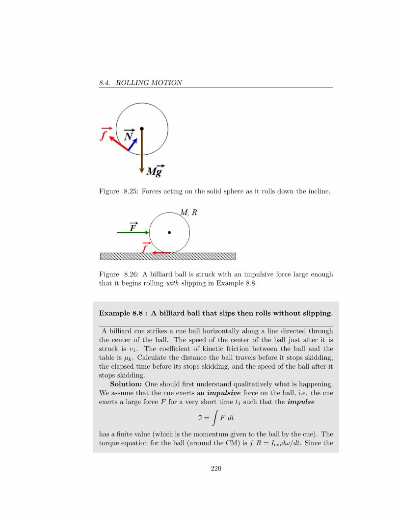
8.4. ROLLING MOTION
Figure 8.25: Forces acting on the solid sphere as it rolls down the incline.
Figure 8.26: A billiard ball is struck with an impulsive force large enoughthat it begins rolling with slipping in Example 8.8.
Example 8.8 : A billiard ball that slips then rolls without slipping.
A billiard cue strikes a cue ball horizontally along a line directed throughthe center of the ball. The speed of the center of the ball just after it isstruck is v1. The coefficient of kinetic friction between the ball and thetable is µk. Calculate the distance the ball travels before it stops skidding,the elapsed time before its stops skidding, and the speed of the ball after itstops skidding.
Solution: One should first understand qualitatively what is happening.We assume that the cue exerts an impulsive force on the ball, i.e. the cueexerts a large force F for a very short time t1 such that the impulse
I =
∫F dt
has a finite value (which is the momentum given to the ball by the cue). Thetorque equation for the ball (around the CM) is f R = Icmdω/dt. Since the
220
8.4. ROLLING MOTION
frictional force f is proportional to the weight of the ball, it does not becomelarge during the time when the cue is hitting the ball. Therefore, if t1 issufficiently small, the angular speed ω is essentially zero just after the cuestrikes the ball. Thus, initially the ball has velocity ~v1 directed to the rightand zero angular velocity. The bottom is skidding and the frictional forceµkMg creates a clockwise angular acceleration α = fR/ICM = (5/2)µkg/R.The frictional force is directed to the left and causes a linear acceleration−µkg of the CM.
As the speed of the center decreases and the clockwise angular velocityincreases, the (rightward) velocity of the bottom molecule relative to thetable decreases. This continues until the instant when the velocity of thebottom molecule is zero. At this instant rolling without slipping commences(the minute roughnesses on the ball engage the roughnesses on the table,like gear teeth), and subsequently the velocity and angular velocity remainconstant.
During the skidding phase, a is constant and the speed of the centerat time t is v = v1 − µkgt. Since the initial angular velocity is zero, wehave (Note that we cannot write α = a/R since this is obtained by takingd/dt(v = ωR), but v = ωR only holds when the bottom molecule has zerovelocity, i.e. no skidding.) ω = αt = 5/2(µkgt/R). The speed of the bottommolecule is vbot = v − ωR = v1 − (7/2)µkgt. The time T when skiddingstops is found by setting vbot = 0, i.e. T = (2/7)(v1/µkg). The distance theball travels while skidding is D = v1T − (1/2)µkgT
2 = (12/49)v21/ukg. The
velocity of the center at time T is v(T ) = v1−µkgT = 5/7v1. Note that thevelocity of the ball when it stops skidding does not depend on µk or g!
If we model the contact between the ball and a floor as taking placeat only one point, then a ball rolling without slipping on a horizontal floorwill never stop rolling. The proof, in words, is: if the frictional force ~f isantiparallel to the velocity of the center, then the velocity will decrease,but the torque produced by ~f will increase the angular velocity (and, if noslipping, the linear velocity must increase); a similar paradox occurs if ~f isparallel to the velocity; therefore f = 0 and a = 0. You can easily write theequations. In order to understand how the ball can stop, we must allow thesurface to exert a force on the ball at more than one point, e.g. by makingthe ball fuzzy or soft, or by letting it sink into a sandy or grassy surface.
221
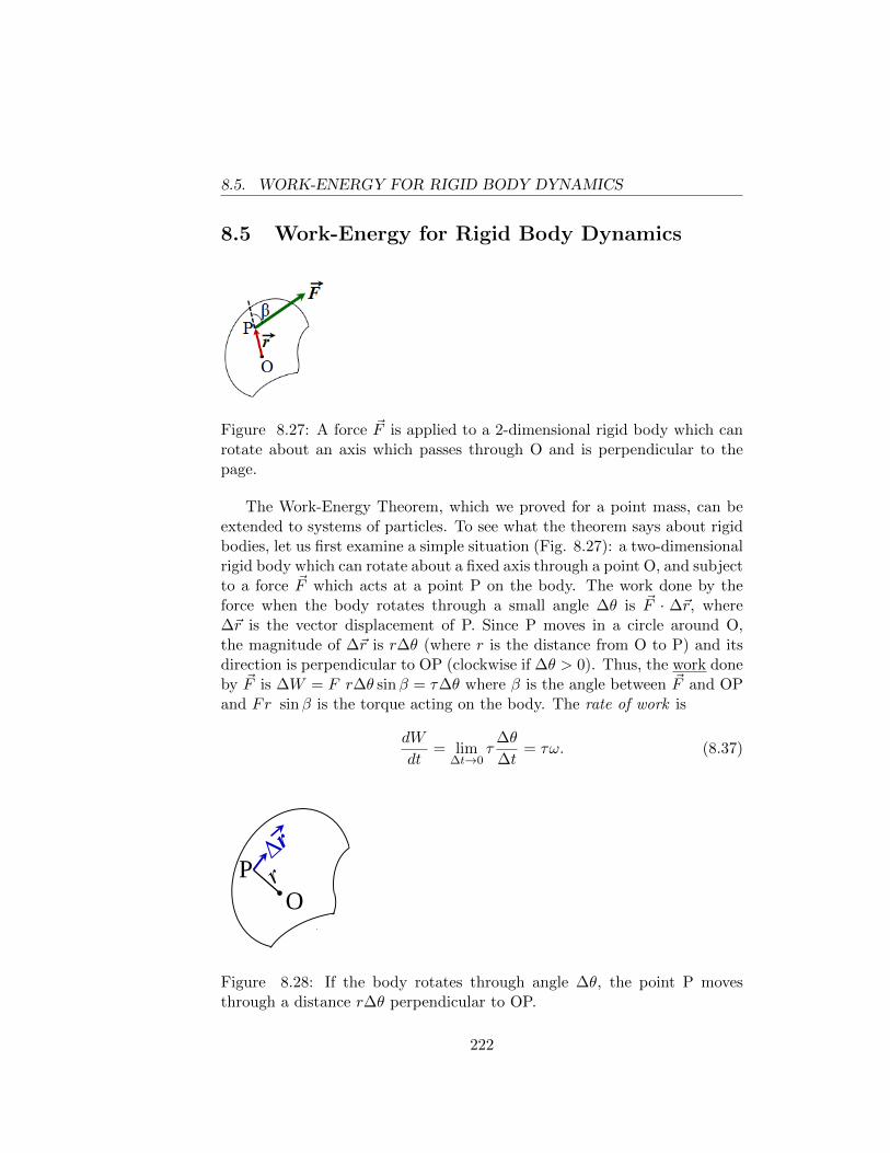
8.5. WORK-ENERGY FOR RIGID BODY DYNAMICS
8.5 Work-Energy for Rigid Body Dynamics
Figure 8.27: A force ~F is applied to a 2-dimensional rigid body which canrotate about an axis which passes through O and is perpendicular to thepage.
The Work-Energy Theorem, which we proved for a point mass, can beextended to systems of particles. To see what the theorem says about rigidbodies, let us first examine a simple situation (Fig. 8.27): a two-dimensionalrigid body which can rotate about a fixed axis through a point O, and subjectto a force ~F which acts at a point P on the body. The work done by theforce when the body rotates through a small angle ∆θ is ~F · ∆~r, where∆~r is the vector displacement of P. Since P moves in a circle around O,the magnitude of ∆~r is r∆θ (where r is the distance from O to P) and itsdirection is perpendicular to OP (clockwise if ∆θ > 0). Thus, the work doneby ~F is ∆W = F r∆θ sinβ = τ∆θ where β is the angle between ~F and OPand Fr sinβ is the torque acting on the body. The rate of work is
dW
dt= lim
∆t→0τ
∆θ
∆t= τω. (8.37)
O P
Figure 8.28: If the body rotates through angle ∆θ, the point P movesthrough a distance r∆θ perpendicular to OP.
222
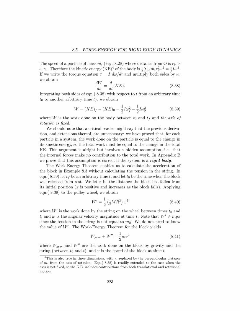
8.5. WORK-ENERGY FOR RIGID BODY DYNAMICS
The speed of a particle of mass mi (Fig. 8.28) whose distance from O is ri, isω ri. Therefore the kinetic energy (KE)4 of the body is 1
2
∑imir
2i ω
2 = 12Iω2.
If we write the torque equation τ = I dω/dt and multiply both sides by ω,we obtain
dW
dt=
d
dt(KE). (8.38)
Integrating both sides of eqn.( 8.38) with respect to t from an arbitrary timet0 to another arbitrary time tf , we obtain
W = (KE)f − (KE)0 =1
2Iω2
f −1
2Iω2
0 (8.39)
where W is the work done on the body between t0 and tf and the axis ofrotation is fixed.
We should note that a critical reader might say that the previous deriva-tion, and extensions thereof, are unnecessary: we have proved that, for eachparticle in a system, the work done on the particle is equal to the change inits kinetic energy, so the total work must be equal to the change in the totalKE. This argument is alright but involves a hidden assumption, i.e. thatthe internal forces make no contribution to the total work. In Appendix Bwe prove that this assumption is correct if the system is a rigid body .
The Work-Energy Theorem enables us to calculate the acceleration ofthe block in Example 8.3 without calculating the tension in the string. Ineqn.( 8.39) let tf be an arbitrary time t, and let t0 be the time when the blockwas released from rest. We let x be the distance the block has fallen fromits initial position (x is positive and increases as the block falls). Applyingeqn.( 8.39) to the pulley wheel, we obtain
W ′ =1
2
(12MR2
)ω2 (8.40)
where W ′ is the work done by the string on the wheel between times t0 andt, and ω is the angular velocity magnitude at time t. Note that W ′ 6= mgxsince the tension in the stirng is not equal to mg. We do not need to knowthe value of W ′. The Work-Energy Theorem for the block yields
Wgrav +W ′′ =1
2mv2 (8.41)
where Wgrav and W ′′ are the work done on the block by gravity and thestring (between t0 and t), and v is the speed of the block at time t.
4This is also true in three dimensions, with ri replaced by the perpendicular distanceof mi from the axis of rotation. Eqn.( 8.38) is readily extended to the case when theaxis is not fixed, so the K.E. includes contributions from both translational and rotationalmotion.
223
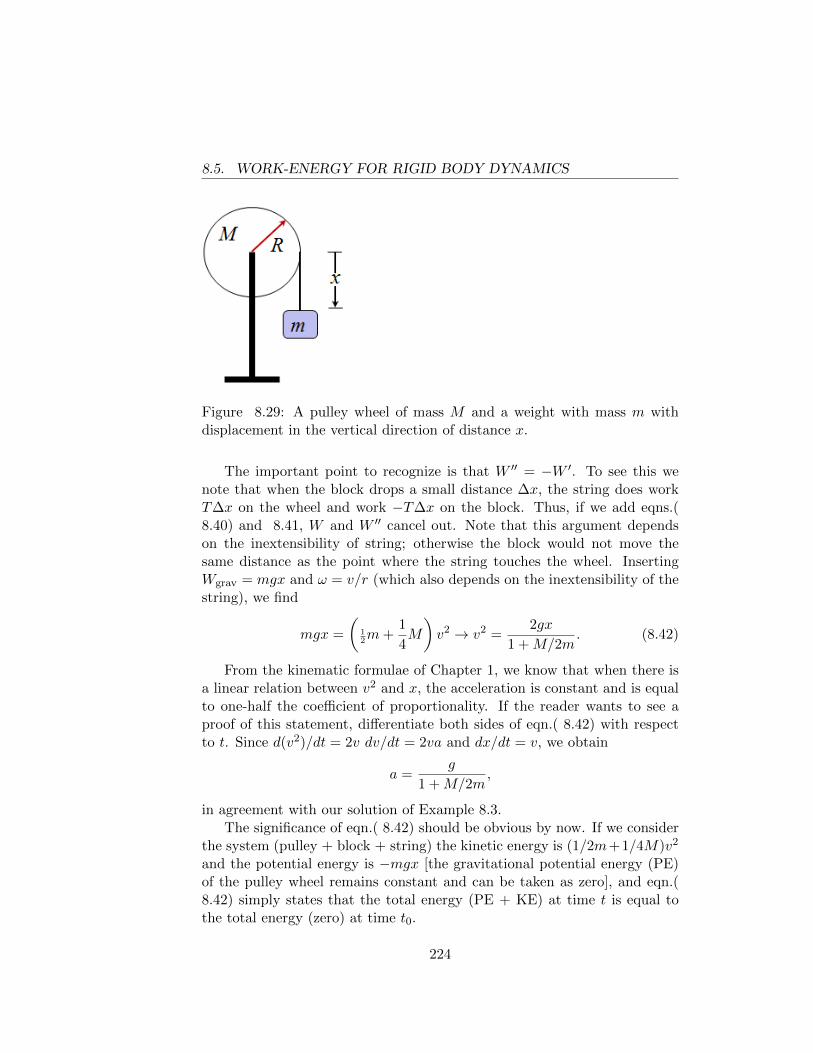
8.5. WORK-ENERGY FOR RIGID BODY DYNAMICS
Figure 8.29: A pulley wheel of mass M and a weight with mass m withdisplacement in the vertical direction of distance x.
The important point to recognize is that W ′′ = −W ′. To see this wenote that when the block drops a small distance ∆x, the string does workT∆x on the wheel and work −T∆x on the block. Thus, if we add eqns.(8.40) and 8.41, W and W ′′ cancel out. Note that this argument dependson the inextensibility of string; otherwise the block would not move thesame distance as the point where the string touches the wheel. InsertingWgrav = mgx and ω = v/r (which also depends on the inextensibility of thestring), we find
mgx =
(12m+
1
4M
)v2 → v2 =
2gx
1 +M/2m. (8.42)
From the kinematic formulae of Chapter 1, we know that when there isa linear relation between v2 and x, the acceleration is constant and is equalto one-half the coefficient of proportionality. If the reader wants to see aproof of this statement, differentiate both sides of eqn.( 8.42) with respectto t. Since d(v2)/dt = 2v dv/dt = 2va and dx/dt = v, we obtain
a =g
1 +M/2m,
in agreement with our solution of Example 8.3.The significance of eqn.( 8.42) should be obvious by now. If we consider
the system (pulley + block + string) the kinetic energy is (1/2m+1/4M)v2
and the potential energy is −mgx [the gravitational potential energy (PE)of the pulley wheel remains constant and can be taken as zero], and eqn.(8.42) simply states that the total energy (PE + KE) at time t is equal tothe total energy (zero) at time t0.
224
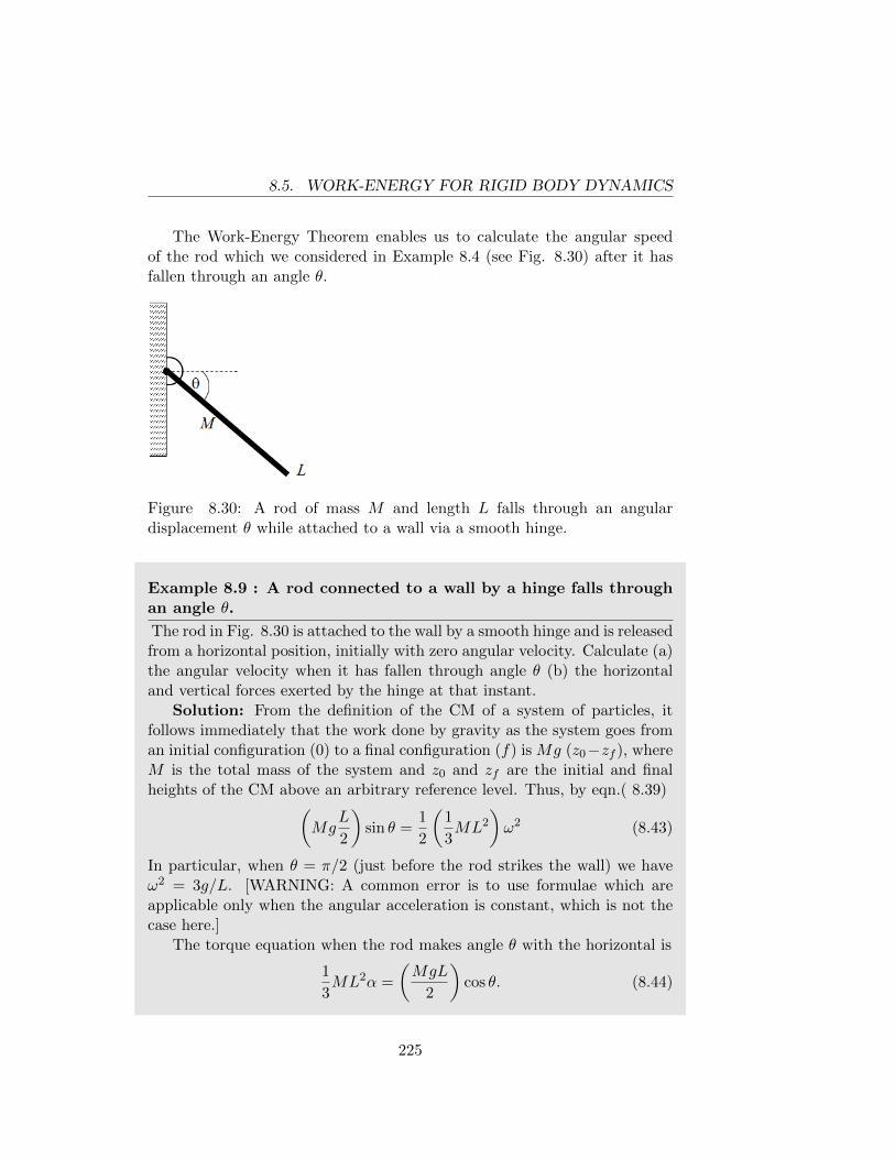
8.5. WORK-ENERGY FOR RIGID BODY DYNAMICS
The Work-Energy Theorem enables us to calculate the angular speedof the rod which we considered in Example 8.4 (see Fig. 8.30) after it hasfallen through an angle θ.
Figure 8.30: A rod of mass M and length L falls through an angulardisplacement θ while attached to a wall via a smooth hinge.
Example 8.9 : A rod connected to a wall by a hinge falls throughan angle θ.
The rod in Fig. 8.30 is attached to the wall by a smooth hinge and is releasedfrom a horizontal position, initially with zero angular velocity. Calculate (a)the angular velocity when it has fallen through angle θ (b) the horizontaland vertical forces exerted by the hinge at that instant.
Solution: From the definition of the CM of a system of particles, itfollows immediately that the work done by gravity as the system goes froman initial configuration (0) to a final configuration (f) is Mg (z0−zf ), whereM is the total mass of the system and z0 and zf are the initial and finalheights of the CM above an arbitrary reference level. Thus, by eqn.( 8.39)(
MgL
2
)sin θ =
1
2
(1
3ML2
)ω2 (8.43)
In particular, when θ = π/2 (just before the rod strikes the wall) we haveω2 = 3g/L. [WARNING: A common error is to use formulae which areapplicable only when the angular acceleration is constant, which is not thecase here.]
The torque equation when the rod makes angle θ with the horizontal is
1
3ML2α =
(MgL
2
)cos θ. (8.44)
225
8.5. WORK-ENERGY FOR RIGID BODY DYNAMICS
Eqn.( 8.43) is derivable as a mathematical consequence of eqn.( 8.44) evenif we never mention work or kinetic energy. Noting that α = d2θ/dt2 andmultiplying both sides of eqn.( 8.44) by dθ/dt we obtain(
1
3ML2
)(dθ
dt
)(d2θ
dt2
)=
(MgL
2
)cos θ
dθ
dt. (8.45)
Since d/dt[(dθ/dt)2] = 2(dθ/dt)(d2θ/dt2) and d/dt(sin θ) = cos θ dθ/dt wecan rewrite eqn.( 8.45) as
d
dt
[1
6ML2
(dθ
dt
)2
− MgL
2sin θ
]= 0.
Therefore the quantity in square brackets is constant, but the value of theconstant is zero since at time zero both θ and dθ/dt vanish. Noting thatdθ/dt = ω, we obtain eqn.( 8.43).
We can calculate the horizontal and vertical forces exerted by the hingeat the instant when the rod has fallen through angle θ by using the theorem(eqn.( 4.9)) ~Fext = M ~ACM. The external forces acting on the rod are gravityand ~H and ~V , the horizontal and vertical forces exerted by the hinge. ThusH = M d2X/dt2 and V − Mg = d2Z/dt2 where X (= L/2 cos θ) andZ(= −L/2 sin θ) are the coordinates of the CM of the rod. Differentiating,we find dX/dt = −L/2 sin θ dθ/dt and d2X/dt2 = −L/2 sin θ d2θ/dt2 −L/2 cos θ (dθ/dt)2. From eqn.( 8.43) and eqn.( 8.44) we have
d2θ
dt2=
3
2
g
Lcos θ(
dθ
dt
)2
=3g
Lsin θ.
Thus we find H = −9/4 Mg sin θ cos θ = −9/8 Mg sin 2θ. Note that thehorizontal force is always directed to the left. A similar calculation (do it!)yields V = Mg/4 (1 + 9 sin2 θ).
The Work-Energy Theorem (the change in KE of a system is equal tothe work done on the system) is true even when some or all of the forcesacting on the system are not conservative. If a force is conservative, we candefine a potential energy (PE) for each configuration of the system. ThePE is the amount of work done by the force as the system moves from that
226
8.5. WORK-ENERGY FOR RIGID BODY DYNAMICS
configuration to some standard configuration (which, by definition, has zeroPE). Thus, if we take θ = 0 (i.e. the rod is horizontal) as the standardconfiguration of the rod in Example 8.9, then the PE when the rod is atangle θ below the horizontal is −MgL/2 sin θ. If all the forces acting on asystem are conservative, then KE + PE = constant, and the value of theconstant is determined by the initial conditions. Thus, in eqn.( 8.43), wecan carry the term on the left across the equal sign and obtain KE + PE =0.
Many problems in rigid-body dynamics can be solved simply by energyconsiderations, without introducting forces and torques. Returning to Ex-ample 8.7, we can take the standard configuration as one in which the pointof contact between the rolling object and the inclined plane is at the lowestpoint on the inclined plane (see Fig. 8.24). Then the gravitational PE isMgx sinβ, where x is the distance from the lowest point on the inclinedplane to the point of contact. When applying the Work-Energy Theorem tothis problem, it is important to realize that the only force which does workon the rolling object is gravity. Although the plane exerts a force on therolling object, this force does no work. The rate of work done by the in-clined plane on the rolling object is ~F ·~v, where ~F is the force exerted by theinclined plane and ~v is the velocity of the matter in the very small surfaceelement (ideally a line or a point) of the rolling object which is touching theincline. in the absence of slipping, ~v = 0 and thus ~F · ~v = 0.
The KE of the rolling object is 12Ipω
2, where Ip is the moment of inertiaabout an axis through the point of contact and perpendicular to the screen(or page). As previously discussed, the parallel-axis theorem yields Ip =ICM +MR2, where ICM = (2/5, 2/3, 1/2, 1)MR2 and the four numericalprefactors refer to a solid sphere, a hollow sphere, a solid cylinder, and ahollow cylinder respectively. If we write KE + PE = constant and replaceω by V/R, where V is the sped of the center of the rolling object, we obtain
1
2
(1 +
ICM
MR2
)MV 2 +Mgx sinβ = const. (8.46)
Differentiating eqn.( 8.46) with respect to t and noting dx/dt = −V anddV/dt = a, we obtain the same value for the acceleration which we previouslyfound.
Before discussing the next Example, we shall state two simple theorems,which are proved in Appendix B and are frequently useful. First, somedefinitions: Let S be any system (a collection of particles, not necessarilya rigid body); let i, j, k be mutually perpendicular axes attached to anarbitrary origin O; let O′ be the CM of the system S, and let i′, j′, k′ be
227
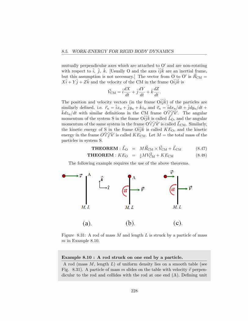
8.5. WORK-ENERGY FOR RIGID BODY DYNAMICS
mutually perpendicular axes which are attached to O′ and are non-rotatingwith respect to i, j, k. [Usually O and the axes ijk are an inertial frame,but this assumption is not necessary.] The vector from O to O′ is ~RCM =Xi+ Y j + Zk and the velocity of the CM in the frame Oijk is
~VCM = idX
dt+ j
dY
dt+ k
dZ
dt.
The position and velocity vectors (in the frame Oijk) of the particles aresimilarly defined. i.e. ~rn = ixn + jyn + kzn and ~vn = idxn/dt + jdyn/dt +kdzn/dt with similar definitions in the CM frame O′i′j′k′. The angularmomentum of the system S in the frame Oijk is called ~LO, and the angularmomentum of the same system in the frame O′i′j′k′ is called ~LCM. Similarly,the kinetic energy of S in the frame Oijk is called KEO, and the kineticenergy in the frame O′i′j′k′ is called KECM. Let M = the total mass of theparticles in system S.
THEOREM : ~LO = M ~RCM × ~VCM + ~LCM (8.47)
THEOREM : KEO = 12MV 2
CM +KECM (8.48)
The following example requires the use of the above theorems.
Figure 8.31: A rod of mass M and length L is struck by a particle of massm in Example 8.10.
Example 8.10 : A rod struck on one end by a particle.
A rod (mass M , length L) of uniform density lies on a smooth table (seeFig. 8.31). A particle of mass m slides on the table with velocity ~v perpen-dicular to the rod and collides with the rod at one end (A). Defining unit
228
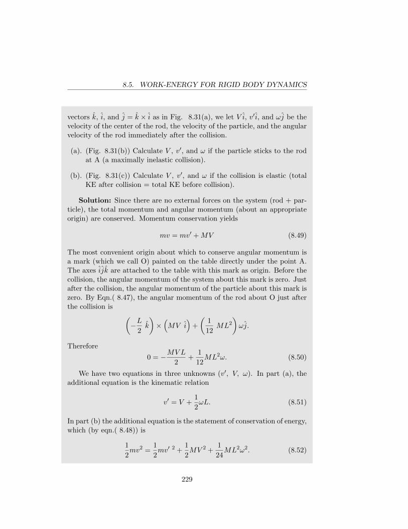
8.5. WORK-ENERGY FOR RIGID BODY DYNAMICS
vectors k, i, and j = k × i as in Fig. 8.31(a), we let V i, v ′i, and ωj be thevelocity of the center of the rod, the velocity of the particle, and the angularvelocity of the rod immediately after the collision.
(a). (Fig. 8.31(b)) Calculate V , v′, and ω if the particle sticks to the rodat A (a maximally inelastic collision).
(b). (Fig. 8.31(c)) Calculate V , v′, and ω if the collision is elastic (totalKE after collision = total KE before collision).
Solution: Since there are no external forces on the system (rod + par-ticle), the total momentum and angular momentum (about an appropriateorigin) are conserved. Momentum conservation yields
mv = mv′ +MV (8.49)
The most convenient origin about which to conserve angular momentum isa mark (which we call O) painted on the table directly under the point A.The axes ijk are attached to the table with this mark as origin. Before thecollision, the angular momentum of the system about this mark is zero. Justafter the collision, the angular momentum of the particle about this mark iszero. By Eqn.( 8.47), the angular momentum of the rod about O just afterthe collision is (
−L2k
)×(MV i
)+
(1
12ML2
)ωj.
Therefore
0 = −MV L
2+
1
12ML2ω. (8.50)
We have two equations in three unknowns (v′, V, ω). In part (a), theadditional equation is the kinematic relation
v′ = V +1
2ωL. (8.51)
In part (b) the additional equation is the statement of conservation of energy,which (by eqn.( 8.48)) is
1
2mv2 =
1
2mv′ 2 +
1
2MV 2 +
1
24ML2ω2. (8.52)
229
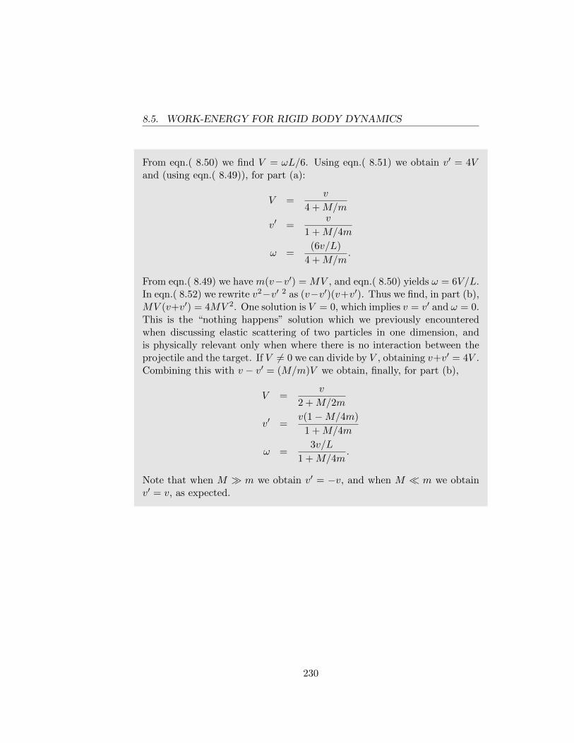
8.5. WORK-ENERGY FOR RIGID BODY DYNAMICS
From eqn.( 8.50) we find V = ωL/6. Using eqn.( 8.51) we obtain v′ = 4Vand (using eqn.( 8.49)), for part (a):
V =v
4 +M/m
v′ =v
1 +M/4m
ω =(6v/L)
4 +M/m.
From eqn.( 8.49) we have m(v−v′) = MV , and eqn.( 8.50) yields ω = 6V/L.In eqn.( 8.52) we rewrite v2−v′ 2 as (v−v′)(v+v′). Thus we find, in part (b),MV (v+v′) = 4MV 2. One solution is V = 0, which implies v = v′ and ω = 0.This is the “nothing happens” solution which we previously encounteredwhen discussing elastic scattering of two particles in one dimension, andis physically relevant only when where there is no interaction between theprojectile and the target. If V 6= 0 we can divide by V , obtaining v+v′ = 4V .Combining this with v − v′ = (M/m)V we obtain, finally, for part (b),
V =v
2 +M/2m
v′ =v(1−M/4m)
1 +M/4m
ω =3v/L
1 +M/4m.
Note that when M � m we obtain v′ = −v, and when M � m we obtainv′ = v, as expected.
230
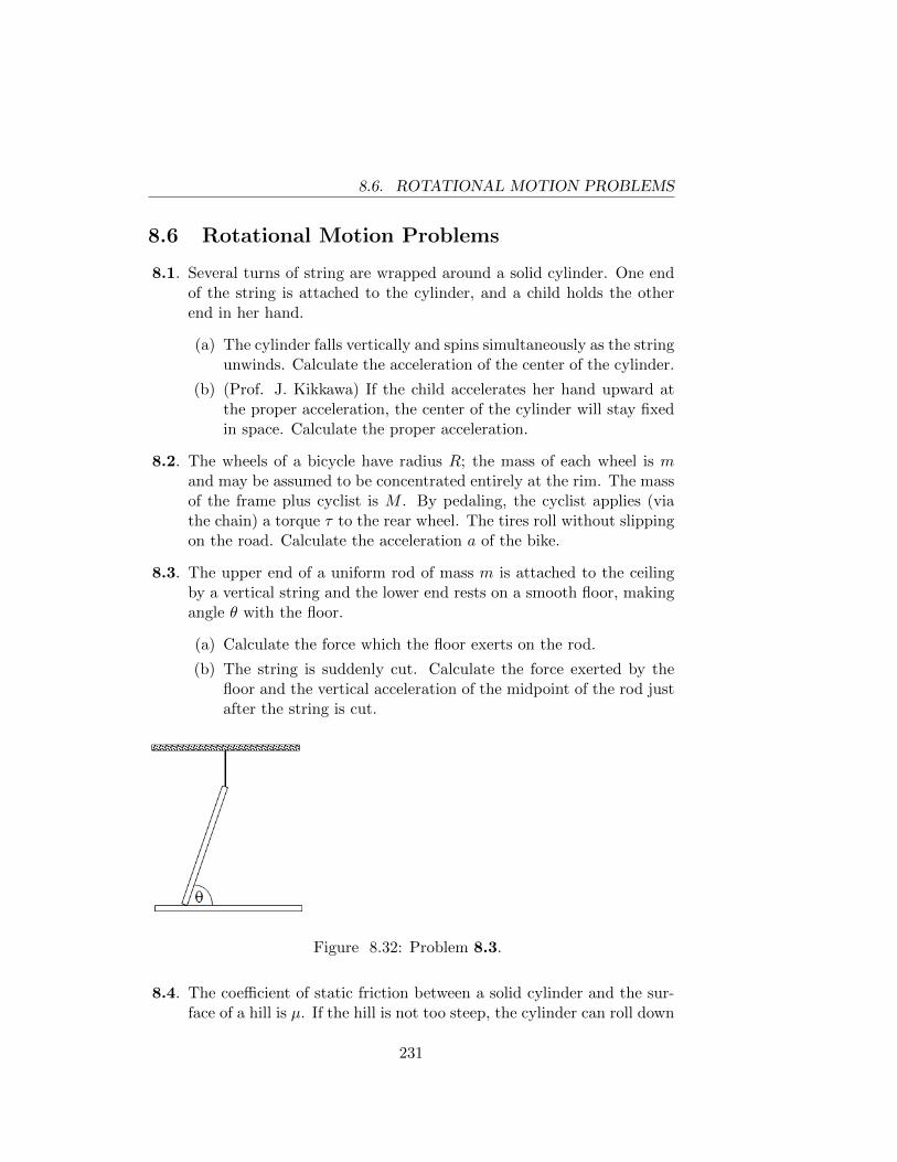
8.6. ROTATIONAL MOTION PROBLEMS
8.6 Rotational Motion Problems
8.1. Several turns of string are wrapped around a solid cylinder. One endof the string is attached to the cylinder, and a child holds the otherend in her hand.
(a) The cylinder falls vertically and spins simultaneously as the stringunwinds. Calculate the acceleration of the center of the cylinder.
(b) (Prof. J. Kikkawa) If the child accelerates her hand upward atthe proper acceleration, the center of the cylinder will stay fixedin space. Calculate the proper acceleration.
8.2. The wheels of a bicycle have radius R; the mass of each wheel is mand may be assumed to be concentrated entirely at the rim. The massof the frame plus cyclist is M . By pedaling, the cyclist applies (viathe chain) a torque τ to the rear wheel. The tires roll without slippingon the road. Calculate the acceleration a of the bike.
8.3. The upper end of a uniform rod of mass m is attached to the ceilingby a vertical string and the lower end rests on a smooth floor, makingangle θ with the floor.
(a) Calculate the force which the floor exerts on the rod.
(b) The string is suddenly cut. Calculate the force exerted by thefloor and the vertical acceleration of the midpoint of the rod justafter the string is cut.
Figure 8.32: Problem 8.3.
8.4. The coefficient of static friction between a solid cylinder and the sur-face of a hill is µ. If the hill is not too steep, the cylinder can roll down
231
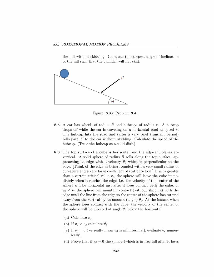
8.6. ROTATIONAL MOTION PROBLEMS
the hill without skidding. Calculate the steepest angle of inclinationof the hill such that the cylinder will not skid.
Figure 8.33: Problem 8.4.
8.5. A car has wheels of radius R and hubcaps of radius r. A hubcapdrops off while the car is traveling on a horizontal road at speed v.The hubcap hits the road and (after a very brief transient period)rolls parallel to the car without skidding. Calculate the speed of thehubcap. (Treat the hubcap as a solid disk.)
8.6. The top surface of a cube is horizontal and the adjacent planes arevertical. A solid sphere of radius R rolls along the top surface, ap-proaching an edge with a velocity ~v0 which is perpendicular to theedge. [Think of the edge as being rounded with a very small radius ofcurvature and a very large coefficient of static friction.] If v0 is greaterthan a certain critical value vc, the sphere will leave the cube imme-diately when it reaches the edge, i.e. the velocity of the center of thesphere will be horizontal just after it loses contact with the cube. Ifv0 < vc the sphere will maintain contact (without slipping) with theedge until the line from the edge to the center of the sphere has rotatedaway from the vertical by an amount (angle) θc. At the instant whenthe sphere loses contact with the cube, the velocity of the center ofthe sphere will be directed at angle θc below the horizontal.
(a) Calculate vc.
(b) If v0 < vc calculate θc.
(c) If v0 = 0 (we really mean v0 is infinitesimal), evaluate θc numer-ically.
(d) Prove that if v0 = 0 the sphere (which is in free fall after it loses
232
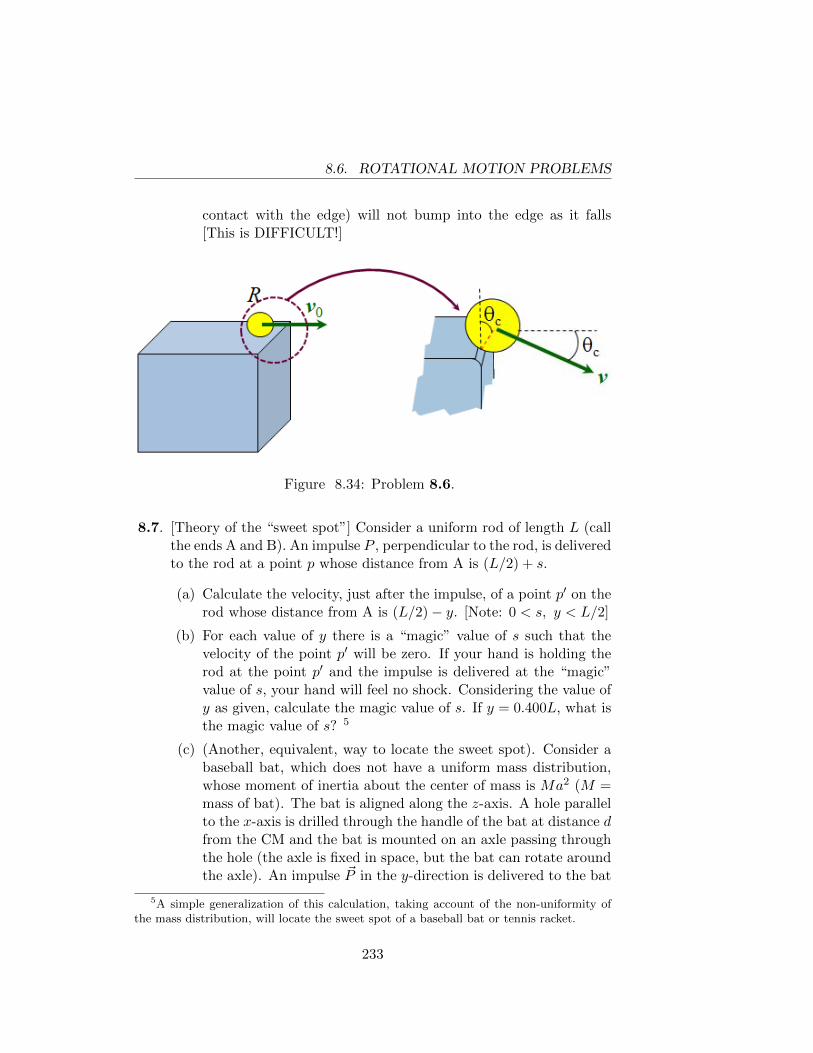
8.6. ROTATIONAL MOTION PROBLEMS
contact with the edge) will not bump into the edge as it falls[This is DIFFICULT!]
Figure 8.34: Problem 8.6.
8.7. [Theory of the “sweet spot”] Consider a uniform rod of length L (callthe ends A and B). An impulse P , perpendicular to the rod, is deliveredto the rod at a point p whose distance from A is (L/2) + s.
(a) Calculate the velocity, just after the impulse, of a point p′ on therod whose distance from A is (L/2)− y. [Note: 0 < s, y < L/2]
(b) For each value of y there is a “magic” value of s such that thevelocity of the point p′ will be zero. If your hand is holding therod at the point p′ and the impulse is delivered at the “magic”value of s, your hand will feel no shock. Considering the value ofy as given, calculate the magic value of s. If y = 0.400L, what isthe magic value of s? 5
(c) (Another, equivalent, way to locate the sweet spot). Consider abaseball bat, which does not have a uniform mass distribution,whose moment of inertia about the center of mass is Ma2 (M =mass of bat). The bat is aligned along the z-axis. A hole parallelto the x-axis is drilled through the handle of the bat at distance dfrom the CM and the bat is mounted on an axle passing throughthe hole (the axle is fixed in space, but the bat can rotate aroundthe axle). An impulse ~P in the y-direction is delivered to the bat
5A simple generalization of this calculation, taking account of the non-uniformity ofthe mass distribution, will locate the sweet spot of a baseball bat or tennis racket.
233
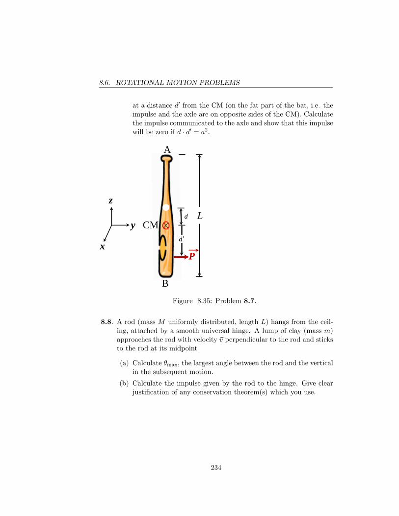
8.6. ROTATIONAL MOTION PROBLEMS
at a distance d′ from the CM (on the fat part of the bat, i.e. theimpulse and the axle are on opposite sides of the CM). Calculatethe impulse communicated to the axle and show that this impulsewill be zero if d · d′ = a2.
L
A
B
P
CM d ′
x
y
z d
Figure 8.35: Problem 8.7.
8.8. A rod (mass M uniformly distributed, length L) hangs from the ceil-ing, attached by a smooth universal hinge. A lump of clay (mass m)approaches the rod with velocity ~v perpendicular to the rod and sticksto the rod at its midpoint
(a) Calculate θmax, the largest angle between the rod and the verticalin the subsequent motion.
(b) Calculate the impulse given by the rod to the hinge. Give clearjustification of any conservation theorem(s) which you use.
234
Chapter 9
REMARKS ON NEWTON’SLAW OF UNIVERSALGRAVITATION -contributed by LarryGladney
For centuries humankind had understood that there are repeating, pre-dictable patterns in the motion of the planets in night sky, in the positionand phases of the Moon, and in the ocean tides. Not until Newton wereall of these patterns to be understood through the application of a singlelaw of physics which, with the accompanying advances in mathematics alsomade by Newton, literally brought the universe into the realm of humanknowledge. This Law of Universal Gravitation is so complete that eventoday it is still used as the basis for understanding the orbits of the hun-dreds of artificial satellites that circle the earth and for engineering the Marslanding missions. It was not until two centuries after Newton that Einsteinrevolutionized our understanding of gravity yet again.
We can only touch on the ramifications that come from Newton’s Lawof Universal Gravitation here. This law, when combined with his three lawsof motion, is the basis for innumerable applications in astronomy, geology,and physics. Remarkably, these connections to other fields are all accessibleto the beginning student of physics. A testament to the genius of Newton isthat his Law of Universal Gravity still has not been supplanted after morethan three centuries of research and thinking on the subject. Although
235
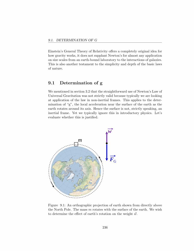
9.1. DETERMINATION OF G
Einstein’s General Theory of Relativity offers a completely original idea forhow gravity works, it does not supplant Newton’s for almost any applicationon size scales from an earth-bound laboratory to the interactions of galaxies.This is also another testament to the simplicity and depth of the basic lawsof nature.
9.1 Determination of g
We mentioned in section 3.2 that the straightforward use of Newton’s Law ofUniversal Gravitation was not strictly valid because typically we are lookingat application of the law in non-inertial frames. This applies to the deter-mination of “g”, the local acceleration near the surface of the earth as theearth rotates around its axis. Hence the surface is not, strictly speaking, aninertial frame. Yet we typically ignore this in introductory physics. Let’sevaluate whether this is justified.
FG
m w
Figure 9.1: An orthographic projection of earth shown from directly abovethe North Pole. The mass m rotates with the surface of the earth. We wishto determine the effect of earth’s rotation on the weight ~w.
236
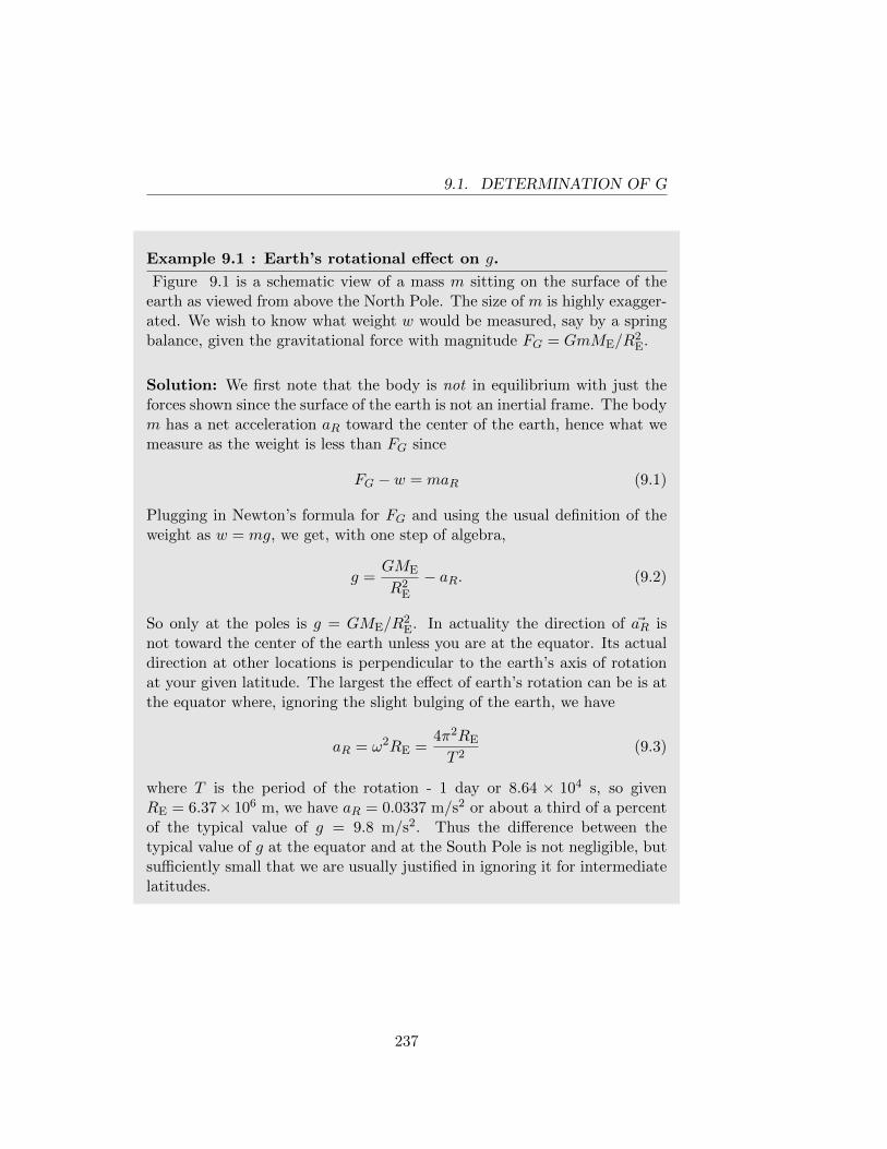
9.1. DETERMINATION OF G
Example 9.1 : Earth’s rotational effect on g.
Figure 9.1 is a schematic view of a mass m sitting on the surface of theearth as viewed from above the North Pole. The size of m is highly exagger-ated. We wish to know what weight w would be measured, say by a springbalance, given the gravitational force with magnitude FG = GmME/R
2E.
Solution: We first note that the body is not in equilibrium with just theforces shown since the surface of the earth is not an inertial frame. The bodym has a net acceleration aR toward the center of the earth, hence what wemeasure as the weight is less than FG since
FG − w = maR (9.1)
Plugging in Newton’s formula for FG and using the usual definition of theweight as w = mg, we get, with one step of algebra,
g =GME
R2E
− aR. (9.2)
So only at the poles is g = GME/R2E. In actuality the direction of ~aR is
not toward the center of the earth unless you are at the equator. Its actualdirection at other locations is perpendicular to the earth’s axis of rotationat your given latitude. The largest the effect of earth’s rotation can be is atthe equator where, ignoring the slight bulging of the earth, we have
aR = ω2RE =4π2RE
T 2(9.3)
where T is the period of the rotation - 1 day or 8.64 × 10⁴ s, so givenRE = 6.37× 10⁶ m, we have aR = 0.0337 m/s2 or about a third of a percentof the typical value of g = 9.8 m/s2. Thus the difference between thetypical value of g at the equator and at the South Pole is not negligible, butsufficiently small that we are usually justified in ignoring it for intermediatelatitudes.
237
9.1. DETERMINATION OF G
Example 9.2 : Effect of altitude on g.
We also take the acceleration g due to gravity as a constant. It is obviousfrom the gravitation law that this is not true as the altitude of a particularlocation on the earth’s surface can place it farther away or closer to theearth’s center. About how large is this altitude effect for “typical” altitudesyou are likely to encounter?
Solution: We want to see how g changes as a function of altitude or changein distance from the earth’s center. For such problems it is usually acceptableto calculate the fractional change. For the case in point, a mass m a distancer from the earth’s center experiences force F due to gravity where
F =GmME
r2⇒
dF = −2GmME
r3dr ⇒
dF
F= −2
dr
r. (9.4)
The result shows that the fractional change in the force is just twice thenegative fractional change in the radius where we note that the negative signis crucial since it indicates that the force magnitude decreases if the changein distance is positive. Let’s assess the fractional change for someone takingoff in an airplane from ground level and cruising at an altitude of 10 km(about 33,000 feet).
F = mg ⇒ dF = m dg ⇒dF
F=dg
g= −2
dr
r(9.5)
= −2104 m
6.37× 10⁶ mdg
g= −0.31% (9.6)
No wonder you never feel any lighter on an airplane ride! A change of 3 partsin a thousand is comparable to the effect due to the earth’s rotation and isnot noticeable for people. However, instruments can easily measure smallerfractions than this and hence use this method to make a crude estimate ofthe shape of the earth, the so-called geoid.
238
9.2. KEPLER’S FIRST LAW OF PLANETARY MOTION
9.2 Kepler’s First Law of Planetary Motion
A comet (e.g. Halley’s comet) moves in a long thin elliptical orbit with thesun at one focus of the ellipse. From our previous discussion of angular mo-mentum conservation in section 8.1, it follows that vtan is maximum whenthe comet is closest to the sun and minimum when the comet is farthestaway. In section 3.2 we enumerated Kepler’s Laws of Planetary Motion andshowed how the second and third of these could be derived from Newton’sLaw of Universal Gravitation. The fact that the orbits of planets or of Hal-ley’s comet must be ellipses was not shown as it requires a little more math.For completeness though, it is reasonable to take what we have learned inprevious chapters to show that elliptical orbits are the exact prediction ofNewton’s prescription of a 1/r2 attractive force law for gravity.
First we note that the problem of considering the trajectory for a point par-ticle moving in the gravitational field of a much more massive body is moreeasily considered in polar coordinates rather than Cartesian ones. The argu-ment for why this should be so is rather simple and due to Newton himself.Experience, and the mathematics of constant acceleration tell us that all tra-jectories of freely moving objects near the surface of the earth are parabolic.Given that we know that objects further from the surface experience a dif-ferent acceleration, how does that affect the trajectory? Newton began histhinking on the subject by first assuming constant gravitational accelerationand doing a thought experiment for the question: what if you fired a pro-jectile horizontally from a cannon atop a very high mountain? Assume themountain is so high that the projectile moves mostly above the atmosphereso that we may ignore air resistance1 (see Fig. 9.2). The projectile willstill initially fall at whatever the local gravitational acceleration determinesalthough its horizontal motion is unchanged. The parabolic path thereforeis still expected. Now however, given the height of the mountain, we canexpect that the range of the projectile is extended beyond what would hap-pen for the same initial speed of a projectile fired from the ground. Giventhe curvature of the earth, we can expect that the projectile must fall fur-ther than just the vertical height of the mountain. Let’s say that the localgravitational acceleration is still about 10 meters/s2. Then, for a sufficientlypowerful cannon we expect that the initial speed of the projectile can be highenough that the range is such that the earth’s surface has “curved away”from the bottom of the mountain so that the projectile must travel further
1Clearly this is all imaginary! There are no such mountains on earth.
239
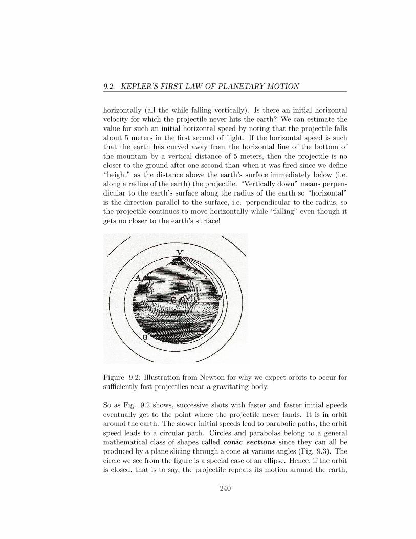
9.2. KEPLER’S FIRST LAW OF PLANETARY MOTION
horizontally (all the while falling vertically). Is there an initial horizontalvelocity for which the projectile never hits the earth? We can estimate thevalue for such an initial horizontal speed by noting that the projectile fallsabout 5 meters in the first second of flight. If the horizontal speed is suchthat the earth has curved away from the horizontal line of the bottom ofthe mountain by a vertical distance of 5 meters, then the projectile is nocloser to the ground after one second than when it was fired since we define“height” as the distance above the earth’s surface immediately below (i.e.along a radius of the earth) the projectile. “Vertically down” means perpen-dicular to the earth’s surface along the radius of the earth so “horizontal”is the direction parallel to the surface, i.e. perpendicular to the radius, sothe projectile continues to move horizontally while “falling” even though itgets no closer to the earth’s surface!
Figure 9.2: Illustration from Newton for why we expect orbits to occur forsufficiently fast projectiles near a gravitating body.
So as Fig. 9.2 shows, successive shots with faster and faster initial speedseventually get to the point where the projectile never lands. It is in orbitaround the earth. The slower initial speeds lead to parabolic paths, the orbitspeed leads to a circular path. Circles and parabolas belong to a generalmathematical class of shapes called conic sections since they can all beproduced by a plane slicing through a cone at various angles (Fig. 9.3). Thecircle we see from the figure is a special case of an ellipse. Hence, if the orbitis closed, that is to say, the projectile repeats its motion around the earth,
240
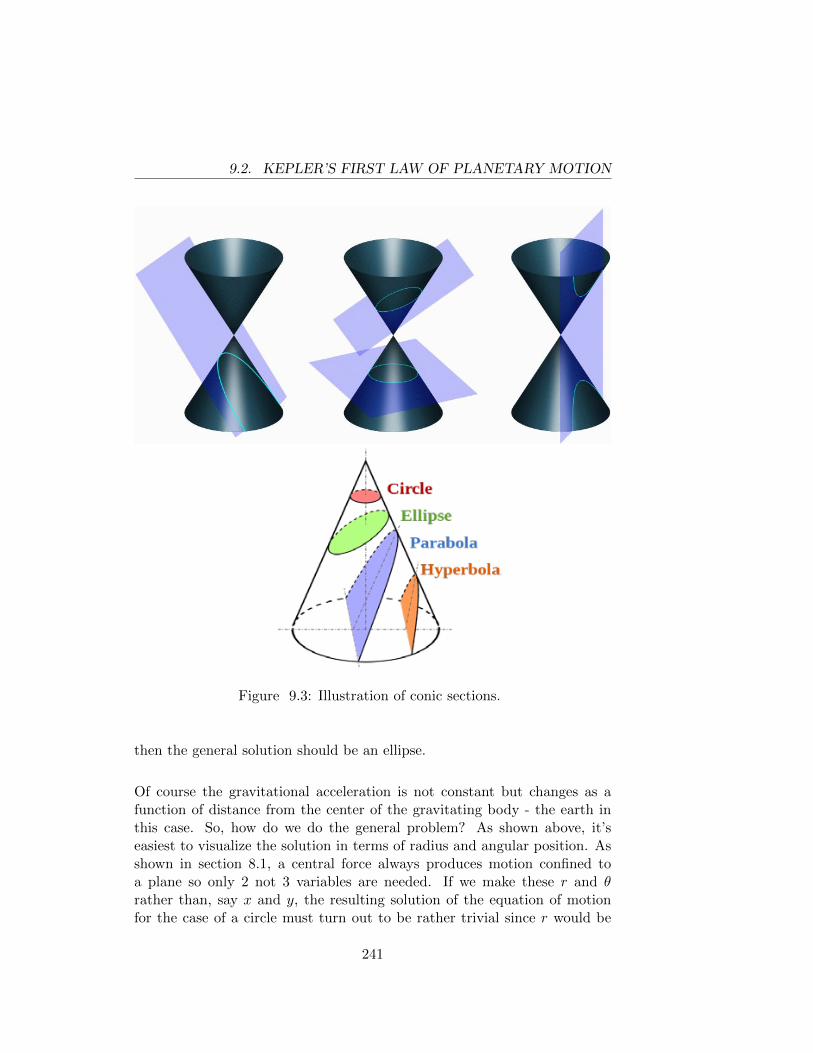
9.2. KEPLER’S FIRST LAW OF PLANETARY MOTION
Figure 9.3: Illustration of conic sections.
then the general solution should be an ellipse.
Of course the gravitational acceleration is not constant but changes as afunction of distance from the center of the gravitating body - the earth inthis case. So, how do we do the general problem? As shown above, it’seasiest to visualize the solution in terms of radius and angular position. Asshown in section 8.1, a central force always produces motion confined toa plane so only 2 not 3 variables are needed. If we make these r and θrather than, say x and y, the resulting solution of the equation of motionfor the case of a circle must turn out to be rather trivial since r would be
241
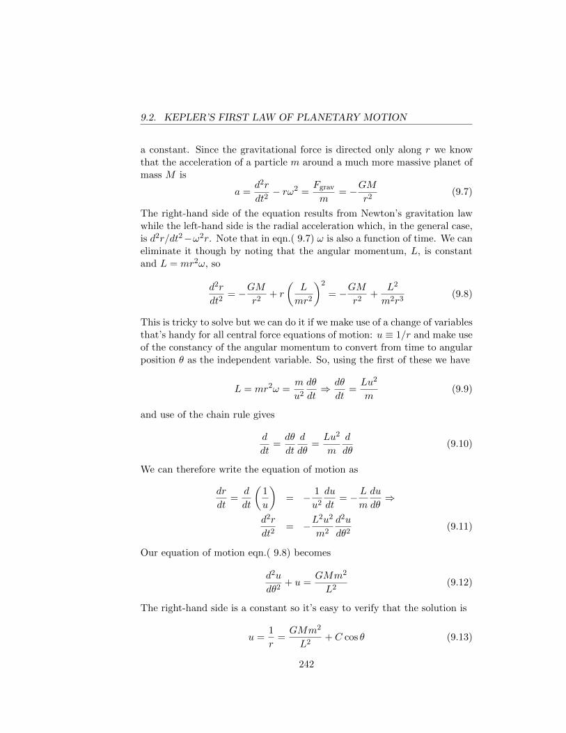
9.2. KEPLER’S FIRST LAW OF PLANETARY MOTION
a constant. Since the gravitational force is directed only along r we knowthat the acceleration of a particle m around a much more massive planet ofmass M is
a =d2r
dt2− rω2 =
Fgrav
m= −GM
r2(9.7)
The right-hand side of the equation results from Newton’s gravitation lawwhile the left-hand side is the radial acceleration which, in the general case,is d2r/dt2−ω2r. Note that in eqn.( 9.7) ω is also a function of time. We caneliminate it though by noting that the angular momentum, L, is constantand L = mr2ω, so
d2r
dt2= −GM
r2+ r
(L
mr2
)2
= −GMr2
+L2
m2r3(9.8)
This is tricky to solve but we can do it if we make use of a change of variablesthat’s handy for all central force equations of motion: u ≡ 1/r and make useof the constancy of the angular momentum to convert from time to angularposition θ as the independent variable. So, using the first of these we have
L = mr2ω =m
u2
dθ
dt⇒ dθ
dt=Lu2
m(9.9)
and use of the chain rule gives
d
dt=dθ
dt
d
dθ=Lu2
m
d
dθ(9.10)
We can therefore write the equation of motion as
dr
dt=
d
dt
(1
u
)= − 1
u2
du
dt= − L
m
du
dθ⇒
d2r
dt2= −L
2u2
m2
d2u
dθ2(9.11)
Our equation of motion eqn.( 9.8) becomes
d2u
dθ2+ u =
GMm2
L2(9.12)
The right-hand side is a constant so it’s easy to verify that the solution is
u =1
r=GMm2
L2+ C cos θ (9.13)
242
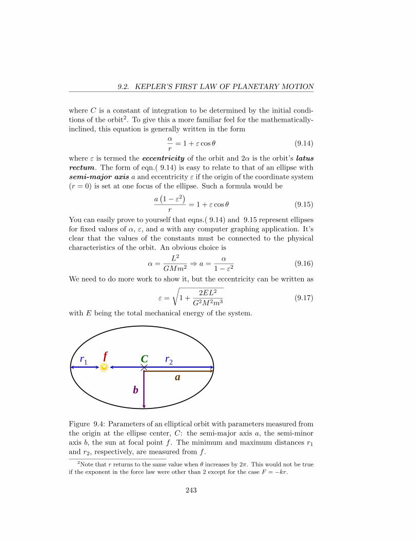
9.2. KEPLER’S FIRST LAW OF PLANETARY MOTION
where C is a constant of integration to be determined by the initial condi-tions of the orbit2. To give this a more familiar feel for the mathematically-inclined, this equation is generally written in the form
α
r= 1 + ε cos θ (9.14)
where ε is termed the eccentricity of the orbit and 2α is the orbit’s latusrectum . The form of eqn.( 9.14) is easy to relate to that of an ellipse withsemi-major axis a and eccentricity ε if the origin of the coordinate system(r = 0) is set at one focus of the ellipse. Such a formula would be
a(1− ε2
)r
= 1 + ε cos θ (9.15)
You can easily prove to yourself that eqns.( 9.14) and 9.15 represent ellipsesfor fixed values of α, ε, and a with any computer graphing application. It’sclear that the values of the constants must be connected to the physicalcharacteristics of the orbit. An obvious choice is
α =L2
GMm2⇒ a =
α
1− ε2(9.16)
We need to do more work to show it, but the eccentricity can be written as
ε =
√1 +
2EL2
G2M2m3(9.17)
with E being the total mechanical energy of the system.
r1 r2 f C
a b
Figure 9.4: Parameters of an elliptical orbit with parameters measured fromthe origin at the ellipse center, C: the semi-major axis a, the semi-minoraxis b, the sun at focal point f . The minimum and maximum distances r1
and r2, respectively, are measured from f .
2Note that r returns to the same value when θ increases by 2π. This would not be trueif the exponent in the force law were other than 2 except for the case F = −kr.
243
9.2. KEPLER’S FIRST LAW OF PLANETARY MOTION
Example 9.3 : Orbits and Halley’s comet.
Sir Edmund Halley determined the orbit of the famous comet that bearshis name. To date it is still the only short-period (namely you can seeit more than once in a human lifetime) comet that is clearly visible tothe human eye from earth. The orbit has a period of about 76 years andan eccentricity of 0.967. Find the maximum and minimum distances ofHalley’s comet from the sun.
Solution: First we should note that the properties of ellipses make it easyto find the minimum and maximum radii (which we denote by r1 and r2,respectively) from the focus (the location of the sun) once we know the meanradius and the eccentricity. You should remember from math class that
r1 = a(1− ε)r2 = a(1 + ε)
where a is the mean radius or semi-major axis, and that
a =r1 + r2
2b =
√r1r2
with b being the semi-minor axis. To get the mean radius in this case weneed to extend the proof of Kepler’s Third Law of Planetary Motion fromsection 3.2 to handle elliptical rather than just circular orbits. To do so it isconvenient to make use of the proof of Kepler’s Second Law from section 8.1,namely that the area swept out for one orbit is the area of the ellipse andthis is a constant due to angular momentum conservation. That is to say,the area A swept out by a line from the focus to the orbiting comet per unittime is
dA
dt=
1
2r2dθ
dt=
L
2m(9.18)
where L is the angular momentum for the orbit. For one complete period Tthe area swept out is just
TdA
dt= T
L
2m= πab (9.19)
since πab is the area of an ellipse. From eqn.( 9.13) we see that the extremaof r occur when θ = 0 and π, and thus
1
r1+
1
r2=r1 + r2
r1r2=
2GMm2
L2(9.20)
244
9.2. KEPLER’S FIRST LAW OF PLANETARY MOTION
which can be rewritten as
2a
b2=
1
2
GM
(dA/dt)2 =1
2
GM
(πab/T )2 (9.21)
and finally
T 2 =4π2a3
GM(9.22)
This is the general form of Kepler’s Third Law appropriate for any closedorbit. For a circle a is just the constant radius. Finally, with this result inhand, we can answer the original question. Note that there are 3.15 × 10⁷
seconds in a year (it’s actually a useful shorthand to remember that this isabout π × 107 s/y).
T 2 =4π2a3
GM⇒
a =
[GMT 2
4π2
]1/3
=
(
6.67× 10⁻¹¹ N·m2
kg2
) (1.99× 1030 kg
) (76 y · π × 107 s
y
)2
4π2
1/3
a = 2.68× 10¹² m⇒rmin = a(1− ε) = 2.68× 10¹² m(1− 0.967) = 8.84× 10¹⁰ m
rmax = a(1 + ε) = 2.68× 10¹² m(1 + 0.967) = 5.27× 10¹² m
245
9.3. GRAVITATIONAL ORBIT PROBLEMS
9.3 Gravitational Orbit Problems
9.1. A space vehicle is initially stationary (with respect to the earth) 300kilometers above the earth’s surface. What velocity (parallel to theearth’s surface) must the vehicle be projected at to achieve circularorbit at that altitude? Also find the period of the orbit.
9.2. The most efficient (in terms of energy expended) way to send a space-craft from the Earth to another planet is to use the Hohmann transferorbit in which the spacecraft is put into an elliptical orbit with a per-ihelion at the (nearly) circular orbit of the Earth around the Sun andthe aphelion at the (nearly) circular orbit of the planet to be vis-ited/invaded. Ignore Earth and Mars gravity. You can find relevantsolar system parameters (mass and distance of Mars from the sun, etc.from any number of textbooks or Internet sources).
(a) Determine the direction the rockets are to be fired for going fromthe Earth to Mars and for the return trip of Mars to Earth.
(b) With what speed must the spacecraft be launched from low Earthorbit and how long does the journey to Mars take?
(c) Where must Mars be (in relation to Earth) when the spacecraftis launched from Earth?
246
Chapter 10
APPENDICES
247

248
Appendix A
Appendix A
A.1 Vectors
Many of the entities with which physics deals (including forces, velocitiesand accelerations) have both a magnitude and a direction. Such entities arecalled vectors. Notationally, vectors are represented by boldface letters or(as in this text) by ordinary letters with arrows above them (for example,~v = velocity).
Newton’s Second Law (in vector notation ~F = m~a) states that the mag-nitude of the acceleration of a particle of mass m is proportional (withproportionality factor 1/m) to the magnitude of the force acting on the par-ticle and the direction of the acceleration is the same as the direction ofthe force. Vector notation provides a compact way of stating the relationbetween the acceleration and the force. If we introduce a set of mutuallyperpendicular x, y, and z axes, the vector equation ~F = m~a is equivalentto three numerical equations (Fx = max, Fy = may, Fz = maz), where Fxis the force in the x-direction and ax is the acceleration in the x-direction,etc. In addition to the virtue of providing a compact way of writing themathematical relation between acceleration and force, the vector notationmakes it clear that this relation does not depend on the orientation of ouraxes (i.e. the directions in which the axes point).
More generally, when we use vector notation in writing an equation, weare stating in compact form a relation (or relations) among the magnitudesand directions of the physical entities represented by the vectors. This re-lation is true, independently of the orientation of our axes, and we are freeto choose the orientation of the axes in whatever way we find convenient.Sometimes (e.g. as in the derivation of the Work-Energy Theorem) it is
249
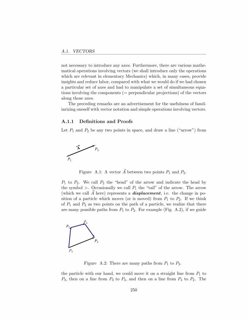
A.1. VECTORS
not necessary to introduce any axes. Furthermore, there are various mathe-matical operations involving vectors (we shall introduce only the operationswhich are relevant in elementary Mechanics) which, in many cases, provideinsights and reduce labor, compared with what we would do if we had chosena particular set of axes and had to manipulate a set of simultaneous equa-tions involving the components (= perpendicular projections) of the vectorsalong those axes.
The preceding remarks are an advertisement for the usefulness of famil-iarizing oneself with vector notation and simple operations involving vectors.
A.1.1 Definitions and Proofs
Let P1 and P2 be any two points in space, and draw a line (“arrow”) from
Figure A.1: A vector ~A between two points P1 and P2.
P1 to P2. We call P2 the “head” of the arrow and indicate the head bythe symbol >. Occasionally we call P1 the “tail” of the arrow. The arrow(which we call ~A here) represents a displacement , i.e. the change in po-sition of a particle which moves (or is moved) from P1 to P2. If we thinkof P1 and P2 as two points on the path of a particle, we realize that thereare many possible paths from P1 to P2. For example (Fig. A.2), if we guide
Figure A.2: There are many paths from P1 to P2.
the particle with our hand, we could move it on a straight line from P1 toP3, then on a line from P3 to P4, and then on a line from P4 to P2. The
250
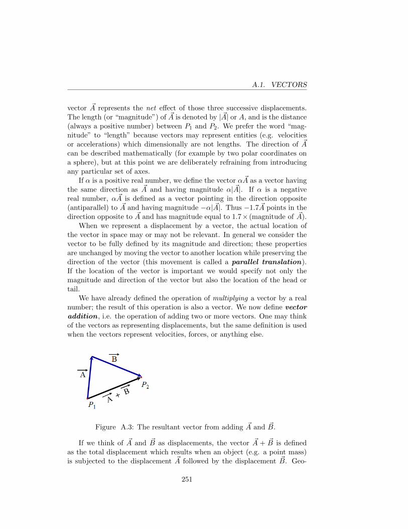
A.1. VECTORS
vector ~A represents the net effect of those three successive displacements.The length (or “magnitude”) of ~A is denoted by | ~A| or A, and is the distance(always a positive number) between P1 and P2. We prefer the word “mag-nitude” to “length” because vectors may represent entities (e.g. velocitiesor accelerations) which dimensionally are not lengths. The direction of ~Acan be described mathematically (for example by two polar coordinates ona sphere), but at this point we are deliberately refraining from introducingany particular set of axes.
If α is a positive real number, we define the vector α ~A as a vector havingthe same direction as ~A and having magnitude α| ~A|. If α is a negativereal number, α ~A is defined as a vector pointing in the direction opposite(antiparallel) to ~A and having magnitude −α| ~A|. Thus −1.7 ~A points in thedirection opposite to ~A and has magnitude equal to 1.7× (magnitude of ~A).
When we represent a displacement by a vector, the actual location ofthe vector in space may or may not be relevant. In general we consider thevector to be fully defined by its magnitude and direction; these propertiesare unchanged by moving the vector to another location while preserving thedirection of the vector (this movement is called a parallel translation).If the location of the vector is important we would specify not only themagnitude and direction of the vector but also the location of the head ortail.
We have already defined the operation of multiplying a vector by a realnumber; the result of this operation is also a vector. We now define vectoraddition , i.e. the operation of adding two or more vectors. One may thinkof the vectors as representing displacements, but the same definition is usedwhen the vectors represent velocities, forces, or anything else.
Figure A.3: The resultant vector from adding ~A and ~B.
If we think of ~A and ~B as displacements, the vector ~A + ~B is definedas the total displacement which results when an object (e.g. a point mass)is subjected to the displacement ~A followed by the displacement ~B. Geo-
251
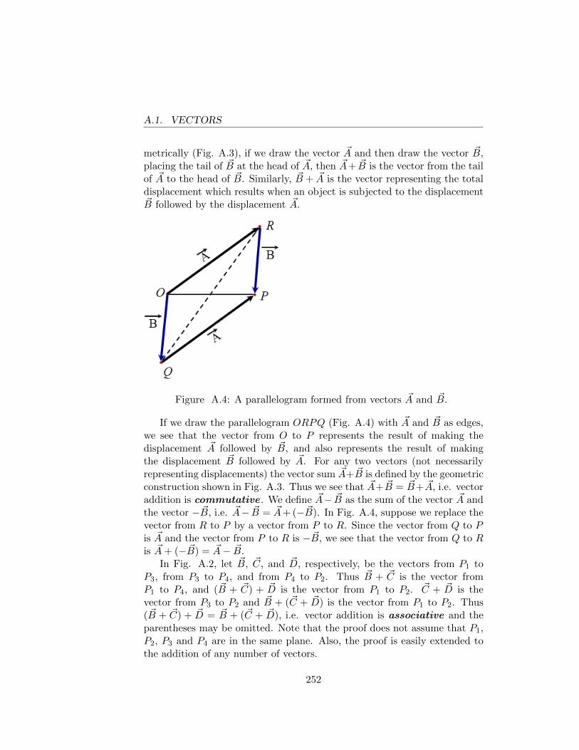
A.1. VECTORS
metrically (Fig. A.3), if we draw the vector ~A and then draw the vector ~B,placing the tail of ~B at the head of ~A, then ~A+ ~B is the vector from the tailof ~A to the head of ~B. Similarly, ~B + ~A is the vector representing the totaldisplacement which results when an object is subjected to the displacement~B followed by the displacement ~A.
Figure A.4: A parallelogram formed from vectors ~A and ~B.
If we draw the parallelogram ORPQ (Fig. A.4) with ~A and ~B as edges,we see that the vector from O to P represents the result of making thedisplacement ~A followed by ~B, and also represents the result of makingthe displacement ~B followed by ~A. For any two vectors (not necessarilyrepresenting displacements) the vector sum ~A+ ~B is defined by the geometricconstruction shown in Fig. A.3. Thus we see that ~A+ ~B = ~B+ ~A, i.e. vectoraddition is commutative . We define ~A− ~B as the sum of the vector ~A andthe vector − ~B, i.e. ~A− ~B = ~A+ (− ~B). In Fig. A.4, suppose we replace thevector from R to P by a vector from P to R. Since the vector from Q to Pis ~A and the vector from P to R is − ~B, we see that the vector from Q to Ris ~A+ (− ~B) = ~A− ~B.
In Fig. A.2, let ~B, ~C, and ~D, respectively, be the vectors from P1 toP3, from P3 to P4, and from P4 to P2. Thus ~B + ~C is the vector fromP1 to P4, and ( ~B + ~C) + ~D is the vector from P1 to P2. ~C + ~D is thevector from P3 to P2 and ~B + (~C + ~D) is the vector from P1 to P2. Thus( ~B + ~C) + ~D = ~B + (~C + ~D), i.e. vector addition is associative and theparentheses may be omitted. Note that the proof does not assume that P1,P2, P3 and P4 are in the same plane. Also, the proof is easily extended tothe addition of any number of vectors.
252
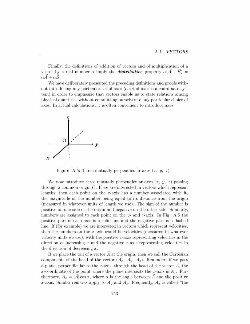
A.1. VECTORS
Finally, the definitions of addition of vectors and of multiplication of avector by a real number α imply the distributive property α( ~A + ~B) =α ~A+ α~B.
We have deliberately presented the preceding definitions and proofs with-out introducing any particular set of axes (a set of axes is a coordinate sys-tem) in order to emphasize that vectors enable us to state relations amongphysical quantities without committing ourselves to any particular choice ofaxes. In actual calculations, it is often convenient to introduce axes.
Figure A.5: Three mutually perpendicular axes (x, y, z).
We now introduce three mutually perpendicular axes (x, y, z) passingthrough a common origin O. If we are interested in vectors which representlengths, then each point on the x-axis has a number associated with it,the magnitude of the number being equal to its distance from the origin(measured in whatever units of length we use). The sign of the number ispositive on one side of the origin and negative on the other side. Similarly,numbers are assigned to each point on the y- and z-axis. In Fig. A.5 thepositive part of each axis is a solid line and the negative part is a dashedline. If (for example) we are interested in vectors which represent velocities,then the numbers on the x-axis would be velocities (measured in whatevervelocity units we use), with the positive x-axis representing velocities in thedirection of increasing x and the negative x-axis representing velocities inthe direction of decreasing x.
If we place the tail of a vector ~A at the origin, then we call the Cartesiancomponents of the head of the vector (Ax, Ay, Az). Reminder: if we pass
a plane, perpendicular to the x-axis, through the head of the vector ~A, thex-coordinate of the point where the plane intersects the x-axis is Ax. Fur-thermore, Ax = | ~A| cosα, where α is the angle between ~A and the positivex-axis. Similar remarks apply to Ay and Az. Frequently, Ax is called “the
253
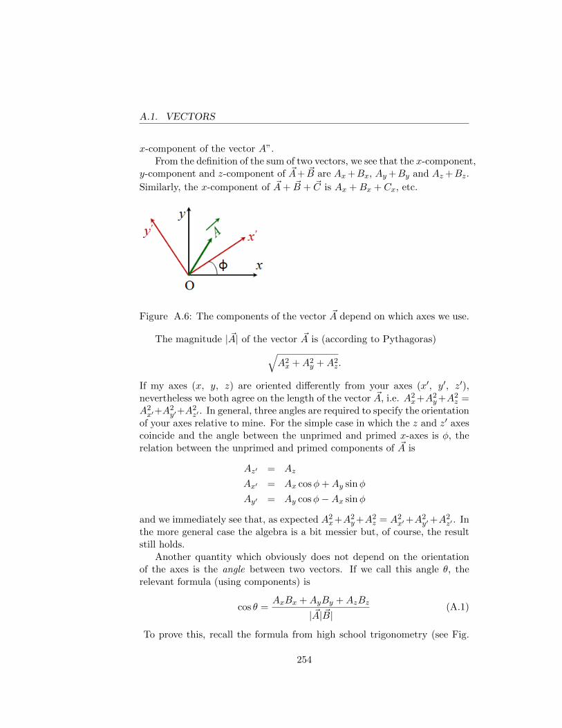
A.1. VECTORS
x-component of the vector A”.From the definition of the sum of two vectors, we see that the x-component,
y-component and z-component of ~A+ ~B are Ax+Bx, Ay +By and Az +Bz.
Similarly, the x-component of ~A+ ~B + ~C is Ax +Bx + Cx, etc.
Figure A.6: The components of the vector ~A depend on which axes we use.
The magnitude | ~A| of the vector ~A is (according to Pythagoras)√A2x +A2
y +A2z.
If my axes (x, y, z) are oriented differently from your axes (x′, y′, z′),nevertheless we both agree on the length of the vector ~A, i.e. A2
x+A2y+A2
z =A2x′+A
2y′+A
2z′ . In general, three angles are required to specify the orientation
of your axes relative to mine. For the simple case in which the z and z′ axescoincide and the angle between the unprimed and primed x-axes is φ, therelation between the unprimed and primed components of ~A is
Az′ = Az
Ax′ = Ax cosφ+Ay sinφ
Ay′ = Ay cosφ−Ax sinφ
and we immediately see that, as expected A2x+A2
y+A2z = A2
x′+A2y′+A
2z′ . In
the more general case the algebra is a bit messier but, of course, the resultstill holds.
Another quantity which obviously does not depend on the orientationof the axes is the angle between two vectors. If we call this angle θ, therelevant formula (using components) is
cos θ =AxBx +AyBy +AzBz
| ~A| ~B|(A.1)
To prove this, recall the formula from high school trigonometry (see Fig.
254
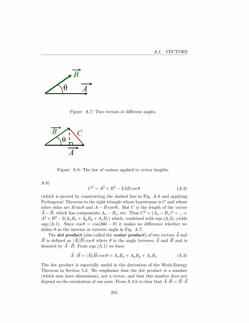
A.1. VECTORS
Figure A.7: Two vectors at different angles.
Figure A.8: The law of cosines applied to vector lengths.
A.8)C2 = A2 +B2 − 2AB cos θ (A.2)
(which is proved by constructing the dashed line in Fig. A.8 and applyingPythagoras’ Theorem to the right triangle whose hypotenuse is C and whoseother sides are B sin θ and A − B cos θ). But C is the length of the vector~A− ~B, which has components Ax −Bx, etc. Thus C2 = (Ax −Bx)2 + ... =A2 +B2− 2(AxBx +AyBy +AzBz) which, combined with eqn.(A.2), yieldseqn.(A.1). Since cos θ = cos(360 − θ) it makes no difference whether wedefine θ as the interior or exterior angle in Fig. A.7.
The dot product (also called the scalar product) of two vectors ~A and~B is defined as | ~A|| ~B| cos θ where θ is the angle between ~A and ~B and isdenoted by ~A · ~B. From eqn.(A.1) we have
~A · ~B = | ~A|| ~B| cos θ = AxBx +AyBy +AzBz. (A.3)
The dot product is especially useful in the derivation of the Work-EnergyTheorem in Section 5.2. We emphasize that the dot product is a number(which may have dimensions), not a vector, and that this number does notdepend on the orientation of our axes. From A.3 it is clear that ~A · ~B = ~B · ~A
255
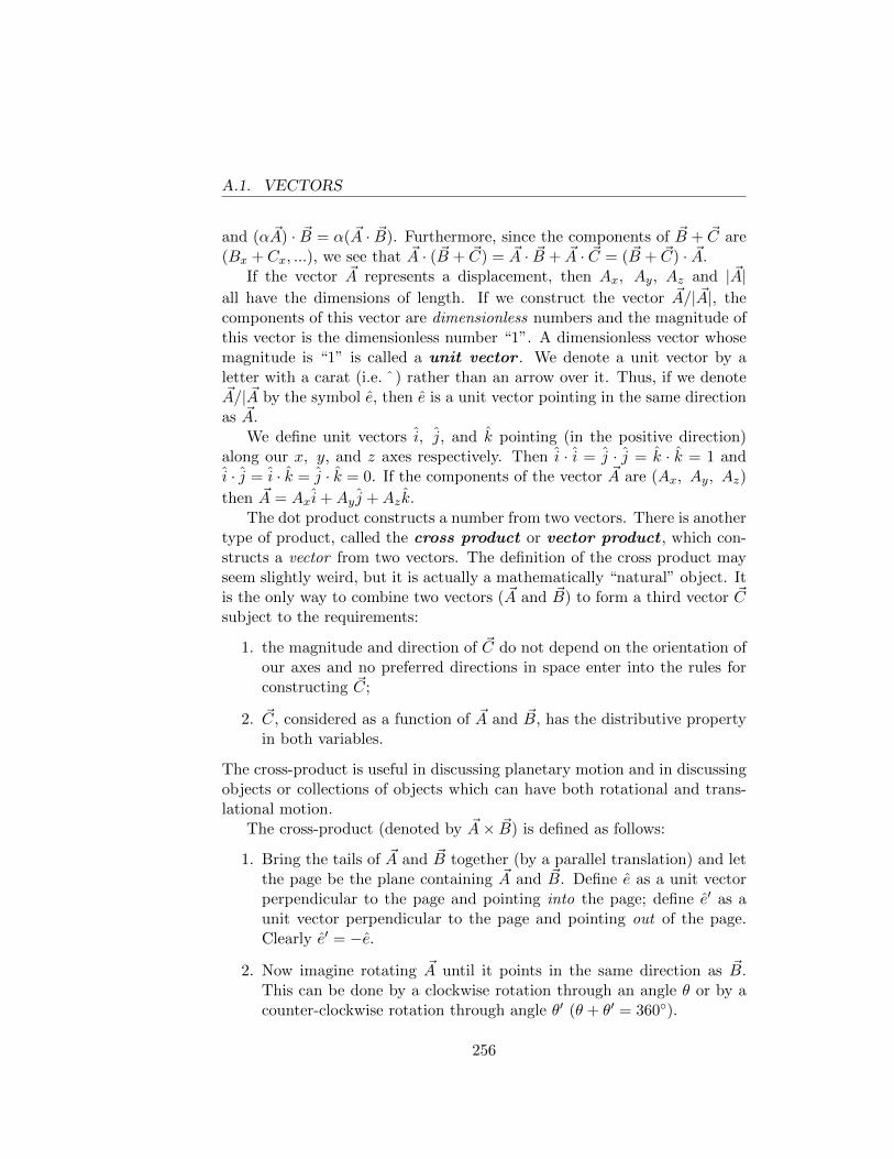
A.1. VECTORS
and (α ~A) · ~B = α( ~A · ~B). Furthermore, since the components of ~B + ~C are(Bx + Cx, ...), we see that ~A · ( ~B + ~C) = ~A · ~B + ~A · ~C = ( ~B + ~C) · ~A.
If the vector ~A represents a displacement, then Ax, Ay, Az and | ~A|all have the dimensions of length. If we construct the vector ~A/| ~A|, thecomponents of this vector are dimensionless numbers and the magnitude ofthis vector is the dimensionless number “1”. A dimensionless vector whosemagnitude is “1” is called a unit vector . We denote a unit vector by aletter with a carat (i.e. ˆ) rather than an arrow over it. Thus, if we denote~A/| ~A by the symbol e, then e is a unit vector pointing in the same directionas ~A.
We define unit vectors i, j, and k pointing (in the positive direction)along our x, y, and z axes respectively. Then i · i = j · j = k · k = 1 andi · j = i · k = j · k = 0. If the components of the vector ~A are (Ax, Ay, Az)
then ~A = Axi+Ay j +Azk.The dot product constructs a number from two vectors. There is another
type of product, called the cross product or vector product , which con-structs a vector from two vectors. The definition of the cross product mayseem slightly weird, but it is actually a mathematically “natural” object. Itis the only way to combine two vectors ( ~A and ~B) to form a third vector ~Csubject to the requirements:
1. the magnitude and direction of ~C do not depend on the orientation ofour axes and no preferred directions in space enter into the rules forconstructing ~C;
2. ~C, considered as a function of ~A and ~B, has the distributive propertyin both variables.
The cross-product is useful in discussing planetary motion and in discussingobjects or collections of objects which can have both rotational and trans-lational motion.
The cross-product (denoted by ~A× ~B) is defined as follows:
1. Bring the tails of ~A and ~B together (by a parallel translation) and letthe page be the plane containing ~A and ~B. Define e as a unit vectorperpendicular to the page and pointing into the page; define e′ as aunit vector perpendicular to the page and pointing out of the page.Clearly e′ = −e.
2. Now imagine rotating ~A until it points in the same direction as ~B.This can be done by a clockwise rotation through an angle θ or by acounter-clockwise rotation through angle θ′ (θ + θ′ = 360◦).
256
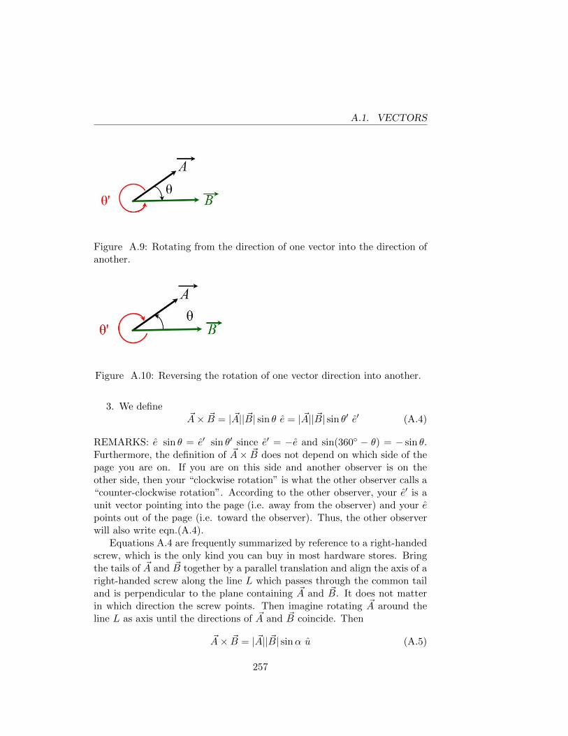
A.1. VECTORS
Figure A.9: Rotating from the direction of one vector into the direction ofanother.
Figure A.10: Reversing the rotation of one vector direction into another.
3. We define~A× ~B = | ~A|| ~B| sin θ e = | ~A|| ~B| sin θ′ e′ (A.4)
REMARKS: e sin θ = e′ sin θ′ since e′ = −e and sin(360◦ − θ) = − sin θ.Furthermore, the definition of ~A× ~B does not depend on which side of thepage you are on. If you are on this side and another observer is on theother side, then your “clockwise rotation” is what the other observer calls a“counter-clockwise rotation”. According to the other observer, your e′ is aunit vector pointing into the page (i.e. away from the observer) and your epoints out of the page (i.e. toward the observer). Thus, the other observerwill also write eqn.(A.4).
Equations A.4 are frequently summarized by reference to a right-handedscrew, which is the only kind you can buy in most hardware stores. Bringthe tails of ~A and ~B together by a parallel translation and align the axis of aright-handed screw along the line L which passes through the common tailand is perpendicular to the plane containing ~A and ~B. It does not matterin which direction the screw points. Then imagine rotating ~A around theline L as axis until the directions of ~A and ~B coincide. Then
~A× ~B = | ~A|| ~B| sinα u (A.5)
257
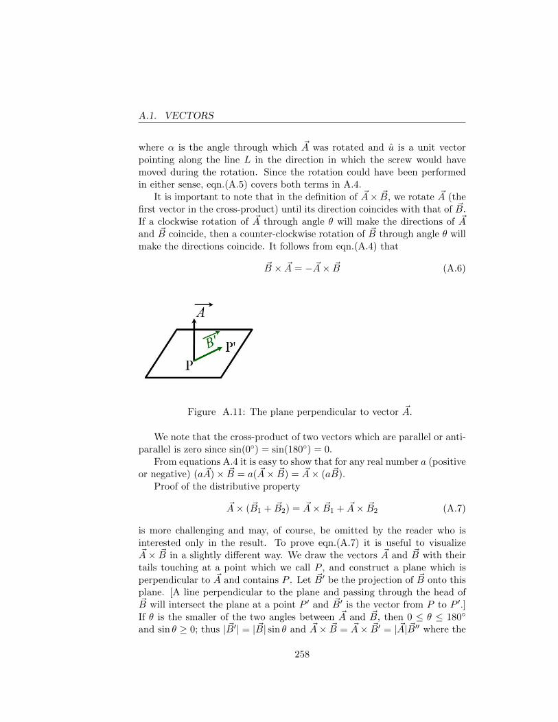
A.1. VECTORS
where α is the angle through which ~A was rotated and u is a unit vectorpointing along the line L in the direction in which the screw would havemoved during the rotation. Since the rotation could have been performedin either sense, eqn.(A.5) covers both terms in A.4.
It is important to note that in the definition of ~A× ~B, we rotate ~A (thefirst vector in the cross-product) until its direction coincides with that of ~B.If a clockwise rotation of ~A through angle θ will make the directions of ~Aand ~B coincide, then a counter-clockwise rotation of ~B through angle θ willmake the directions coincide. It follows from eqn.(A.4) that
~B × ~A = − ~A× ~B (A.6)
Figure A.11: The plane perpendicular to vector ~A.
We note that the cross-product of two vectors which are parallel or anti-parallel is zero since sin(0◦) = sin(180◦) = 0.
From equations A.4 it is easy to show that for any real number a (positiveor negative) (a ~A)× ~B = a( ~A× ~B) = ~A× (a ~B).
Proof of the distributive property
~A× ( ~B1 + ~B2) = ~A× ~B1 + ~A× ~B2 (A.7)
is more challenging and may, of course, be omitted by the reader who isinterested only in the result. To prove eqn.(A.7) it is useful to visualize~A× ~B in a slightly different way. We draw the vectors ~A and ~B with theirtails touching at a point which we call P , and construct a plane which isperpendicular to ~A and contains P . Let ~B′ be the projection of ~B onto thisplane. [A line perpendicular to the plane and passing through the head of~B will intersect the plane at a point P ′ and ~B′ is the vector from P to P ′.]If θ is the smaller of the two angles between ~A and ~B, then 0 ≤ θ ≤ 180◦
and sin θ ≥ 0; thus | ~B′| = | ~B| sin θ and ~A× ~B = ~A× ~B′ = | ~A| ~B′′ where the
258
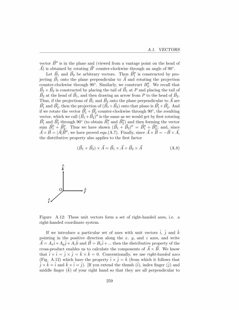
A.1. VECTORS
vector ~B′′ is in the plane and (viewed from a vantage point on the head of~A) is obtained by rotating ~B′ counter-clockwise through an angle of 90◦.
Let ~B1 and ~B2 be arbitrary vectors. Then ~B′′1 is constructed by pro-jecting ~B1 onto the plane perpendicular to ~A and rotating the projectioncounter-clockwise through 90◦. Similarly, we construct B′′2 . We recall that~B1 + ~B2 is constructed by placing the tail of ~B1 at P and placing the tail of~B2 at the head of ~B1, and then drawing an arrow from P to the head of ~B2.Thus, if the projections of ~B1 and ~B2 onto the plane perpendicular to ~A are~B′1 and ~B′2, then the projection of ( ~B1 + ~B2) onto that plane is ~B′1 + ~B′2. Andif we rotate the vector ~B′1 + ~B′2 counter-clockwise through 90◦, the resultingvector, which we call ( ~B1 + ~B2)′′ is the same as we would get by first rotating~B′1 and ~B′2 through 90◦ (to obtain ~B′′1 and ~B′′2 ) and then forming the vectorsum ~B′′1 + ~B′′2 . Thus we have shown ( ~B1 + ~B2)′′ = ~B′′1 + ~B′′2 ; and, since~A× ~B = | ~A| ~B′′, we have proved eqn.(A.7). Finally, since ~A× ~B = − ~B × ~A,the distributive property also applies to the first factor
( ~B1 + ~B2)× ~A = ~B1 × ~A+ ~B2 × ~A (A.8)
Figure A.12: These unit vectors form a set of right-handed axes, i.e. aright-handed coordinate system.
If we introduce a particular set of axes with unit vectors i, j and kpointing in the positive direction along the x, y, and z axes, and write~A = Axi+Ay j+Azk and ~B = Bxi+ ... then the distributive property of the
cross-product enables us to calculate the components of ~A × ~B. We knowthat i × i = j × j = k × k = 0. Conventionally, we use right-handed axes(Fig. A.12) which have the property i × j = k (from which it follows thatj × k = i and k × i = j). [If you extend the thumb (i), index finger (j) andmiddle finger (k) of your right hand so that they are all perpendicular to
259
A.1. VECTORS
each other, they form a right-handed set of axes.] We find
~A× ~B = (AyBz −AzBy )i+ (AzBx −AxBz)j + (AxBy −AyBx)k. (A.9)
Frequently we deal with vectors which vary with time. For example, if~r is the vector from a fixed origin to the instantaneous position of a movingparticle, then d~r/dt is the velocity vector of the particle. The derivative of avector ~A(t) is defined in exactly the same way as the derivative of a functionf(t), i.e.
d ~A
dt= lim
∆t→0
~A(t+ ∆t)− ~A(t)
∆t(A.10)
If ~A = Axi + Ay j + Azk and the unit vectors i, j, k are constant in time,then
d ~A
dt= i
dAxdt
+ jdAydt
+ kdAzdt
.
The derivative of the dot product can be obtained directly from eqn.(A.3)or (without introducing unit vectors) from eqn.(A.10). For example
d
dt
(~A · ~B
)= lim
∆t→0
[~A(t+ ∆t) · ~B(t+ ∆t)− ~A(t) · ~B(t)
]∆t
. (A.11)
If we add zero (in the form ~A(t+∆t)· ~B(t)− ~A(t+∆t)· ~B(t)) to the numeratorof eqn.(A.11), then the right side of that equation becomes[
~A(t+ ∆t) ·(~B(t+ ∆t)− ~B(t)
)+(~A(t+ ∆t)− ~A(t)
)· ~B(t)
]∆t
Letting ∆t→ 0 we obtain
d
dt
(~A · ~B
)= ~A · d
~B
dt+d ~A
dt· ~B (A.12)
and note that the order of the factors in the two terms is irrelevant since~a ·~b = ~b ·~a. We can carry out the same manipulations for the cross-product(substituting × for ·) but must be careful to preserve the order of the factorssince ~a×~b = −~b× ~a. Thus we obtain
d
dt
(~A× ~B
)= ~A×
(d ~B
dt
)+
(d ~A
dt
)× ~B. (A.13)
260
Appendix B
Appendix B
B.1 Useful Theorems about Energy, Angular Mo-mentum, & Moment of Inertia
Recall the definition of the center of mass (CM) of a collection of particles:
M ~RCM =∑i
mi ~ri (M =∑i
mi). (B.1)
Equivalently ∑i
mi ~r′i = 0 where ~r ′i = ~ri − ~RCM (B.2)
Differentiating eqn.(B.2) with respect to time we obtain∑i
mi~v′i = 0 where ~v ′i =
d~r ′idt
= ~vi − ~VCM (B.3)
Suppose we have an inertial frame Oijk (an appropriate origin O anda set of axes non-rotating with respect to distant stars) and another frameO′i′j′k′ (where O′ is the CM of our system and i′j′k′ are also non-rotating).The kinetic energy (KE) of our system, as measured in the frame Oijk, is
KEO =1
2
∑i
mi v2i .
The KE as measured in the frame O′i′j′k′ is
KECM =1
2
∑i
mi v′2i . (B.4)
261
B.1. USEFUL THEOREMS ABOUT ENERGY, ANGULARMOMENTUM, & MOMENT OF INERTIA
THEOREM: KEO = KECM + 12MV 2
CM.
The proof is simply to write v2i =
(~v ′i + ~VCM
)·(~v ′i + ~VCM
)and to note
that the cross-term in the square vanishes because∑mi ~v
′i = 0.
The angular momentum, as measured in the frame Oijk, is
~LO =∑i
mi~ri × ~vi.
We replace ~ri by ~RCM + ~r ′i and ~vi by ~VCM + ~v ′i . Two of the four terms in
the expansion of ~LO vanish [~RCM ×∑mi~v
′i = 0 and
∑mi~r
′i × ~VCM = 0].
Defining~LCM =
∑i
mi~r′i × ~vi
′
we have the
THEOREM : ~LO = ~LCM +M ~RCM × ~VCM. (B.5)
We have already discussed the fact that the internal forces in a systemmake no contribution to the total force and total torque acting on the system.We derived the result ~τ0, ext = d~L0/dt where
~τ0, ext =∑i
~ri × ~Fi, ext
and ~Fext is the external force acting on the ith particle. Writing ~ri = ~r ′i +~RCM we find
~τ0, ext = ~τCM, ext + ~RCM × ~Fext
where ~τCM, ext is the torque (due to external forces) measured in the CM
system and ~Fext is the total external force. We note from eqn.(B.5)
d~L0
dt=d~LCM
dt+M~VCM × ~VCM + ~RCM ×M ~ACM. (B.6)
The second term on the right of eqn.(B.6) is zero and the third term is equalto ~RCM × ~Fext. Thus we find
THEOREM : ~τCM, ext =d~LCM
dt. (B.7)
In particular, this theorem implies that when an object (or collection ofobjects) is falling under the influence of a uniform gravitational field, the
262
B.1. USEFUL THEOREMS ABOUT ENERGY, ANGULARMOMENTUM, & MOMENT OF INERTIA
angular momentum of the system around its CM remains constant (sincegravity exerts no torque around the CM).
Recall that the moment of inertia of a body, around a line L, is the sumover the mass elements of the body of the mass of the element multipliedby the square of the distance of the element from the line L. A usefultheorem, most easily stated in words, is the parallel axis theorem : If Iis the moment of inertia of a body about a line L and I ′ is the moment ofinertia of the body about a line L′ which is parallel to L and passes throughthe CM, then I = I ′ +Ma2 where a is the perpendicular distance betweenL and L′ and M is the mass of the body.Proof : Let O be a point on the line L and let e be a unit vector pointing(in either sense) along L. Let ~ri be a vector from O to the mass element mi.Then
I =∑i
mi
[~ri · ~ri − (e · ~ri)2
].
If O′ is the CM and ~r ′i is the vector from O′ to mass element mi, then I ′ =∑mi
[~r ′i · ~r ′i − (e · ~r ′i )2
]. If ~R is the vector from O to O′ then ~ri = ~R+~r ′i .
Inserting this into the expression for I we see that the terms 2~R ·∑mi~r
′i
and 2e ·∑mi~r
′i vanish since
∑mi~r
′i = 0. Thus
I = I ′ +M
[~R · ~R−
(e · ~R
)2]
= I ′ +Ma2.
In Chapter 8 we discussed some simple examples of rigid body motionin which the angular velocity ωj is perpendicular to the page and the bodyis a figure of revolution about the axis of rotation j. We are interestedin the angular momentum ~LO =
∑~ri ×mi~vi, where O is a point fixed in
the body and ~ri is the vector from O to mi and ~vi = d~ri/dt. We write~ri = xi i + yi j + zi k where i, j, k are vectors fixed in the body. Thecoordinates xi, yi, zi do not change in time, but the unit vectors i andk rotate with the body. One easily sees di/dt = ω j × i = −ω k anddk/dt = ω j × k = ω i. Thus ~vi = −ωxi k + ωzi i and
~LO = ω∑i
mi
[(x2i + z2
i
)j − xiyi i− yizi k
]. (B.8)
The first term on the right side of eqn.(B.8) is just the moment of inertiaabout the axis j through the point O. The other terms vanish if the objecthas sufficient symmetry: if the body is a figure of revolution about the y-axis, then if there is a mass element at (x, y) there is an equal mass element
263
B.1. USEFUL THEOREMS ABOUT ENERGY, ANGULARMOMENTUM, & MOMENT OF INERTIA
at (−x, y) and the second sum on the right vanishes (as does the thirdsum); similarly, if the body is symmetric about the plane y = 0 so thatthere are equal mass elements at (x, y) and (x, −y), then the second andthird sums on the right vanish. In these cases we can write ~L = Iω j, as inthe two-dimensional case.
In Chapter 8 we proved the Work-Energy Theorem for a rigid bodyrotating about a fixed axis (see eqns.( 8.37) and ( 8.38)). Extension of theproof of Chapter 8, by using the force and torque equations describing anarbitrary motion of a rigid body, involves some slightly complicated vectormanipulations which are not appropriate for inclusion here. However, as wementioned in Chapter 8, since we have proved that, for each particle in asystem, the work done on the particle is equal to the change in its K.E., theWork-Energy Theorem will apply to the system as a whole provided we canshow that the internal forces make no contribution to the total work. It isessential to assume that the system is a rigid body since the internal forceswill usually do work if the distances between the particles change.
Consider a pair of particles whose positions (with respect to some axes)at a certain instant are ~ri and ~rj , and slightly later the positions are ~ri+∆~riand ~rj + ∆~rj . The vector from i to j is ~rij = ~rj − ~ri and the square of thedistance between the two particles is ~rij · ~rij . If the body is rigid, theinterparticle distances don’t change; thus (through first order in the smallquantities) ~rij · ∆~rij = 0, where ∆~rij = ∆~rj − ∆~ri. If the force exerted
by i on j is ~fij (and the force exerted by j on i is −~fij) then the work
done by i on j is ~fij ·∆~rj and the work done by j on i is −~fij ·∆~ri. The
sum of the two works is ~fij · ∆~rij . This dot product will be zero if ~fij isparallel or anti-parallel to ~rij , i.e. if the forces are central forces. The onlynon-central forces are those between steady currents (i.e. moving charges)in matter. The magnetic force on a moving charge is always perpendicularto the velocity of the charge and therefore does no work [this part of theargument does not require that the system be a rigid body].
CONCLUSION: the Work-Energy Theorem applies to a rigid body withonly external forces contributing to the work.
264
Appendix C
Appendix C
C.1 Proof That Force Is A Vector
It is frequently asserted that it is an experimental fact that force is a vector.Indeed this is true since if ~F = m~a, then ~F must be a vector since ~a isdefinitely a vector. Recall that in chapter 2 we defined ~F independently ofmotion, the unit of force being the push or pull exerted by some standardobject (“the mouse”). A team of n mice pulling in a given direction wasrepresented by an arrow of length n pointing in that direction (see Fig.2.1which we reproduce here). If we introduce x and y axes making angles of θand 90◦−θ with the direction in which the n mice are pulling, do we need todo an experiment to demonstrate that the team of n mice is equivalent to apair of teams: n cos θ mice pulling along the x-axis and n sin θ mice pullingalong the y-axis?
I claim we can prove this by pure thought.
Suppose 0 ≤ θ ≤ 90◦, i.e. the team are pulling in the first quadrant. Iregard it as clear that if appropriate numbers (n1, n2) of mice pull in thenegative directions along the x- and y-axes, the tug-of-war will be a tie. Ifone requires a “proof” of this, it is clear that as the ratio n1/n2 is varied thedirection of the resultant pull due to the teams on the axes will vary, andwill be in the opposite direction from the pull of the n-team when the ratiohas the “right” value. Then, by multiplying n1 and n2 by the same factor,one can adjust the magnitude of the resultant pull so as to cancel that ofthe n-team.
If we now let the teams of n1 and n2 pull in the positive directions alongthe x and y-axes, we can say that the pair of teams is equivalent to the
265
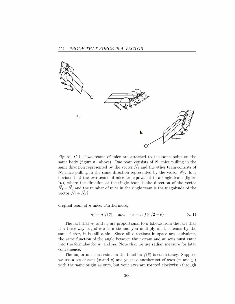
C.1. PROOF THAT FORCE IS A VECTOR
Figure C.1: Two teams of mice are attached to the same point on thesame body (figure a. above). One team consists of N1 mice pulling in thesame direction represented by the vector ~N1 and the other team consists ofN2 mice pulling in the same direction represented by the vector ~N2. Is itobvious that the two teams of mice are equivalent to a single team (figureb.), where the direction of the single team is the direction of the vector~N1 + ~N2 and the number of mice in the single team is the magnitude of thevector ~N1 + ~N2?
original team of n mice. Furthermore,
n1 = n f(θ) and n2 = n f(π/2− θ) (C.1)
The fact that n1 and n2 are proportional to n follows from the fact thatif a three-way tug-of-war is a tie and you multiply all the teams by thesame factor, it is still a tie. Since all directions in space are equivalent,the same function of the angle between the n-team and an axis must enterinto the formulas for n1 and n2. Note that we use radian measure for laterconvenience.
The important constraint on the function f(θ) is consistency. Supposewe use a set of axes (x and y) and you use another set of axes (x′ and y′)with the same origin as ours, but your axes are rotated clockwise (through
266
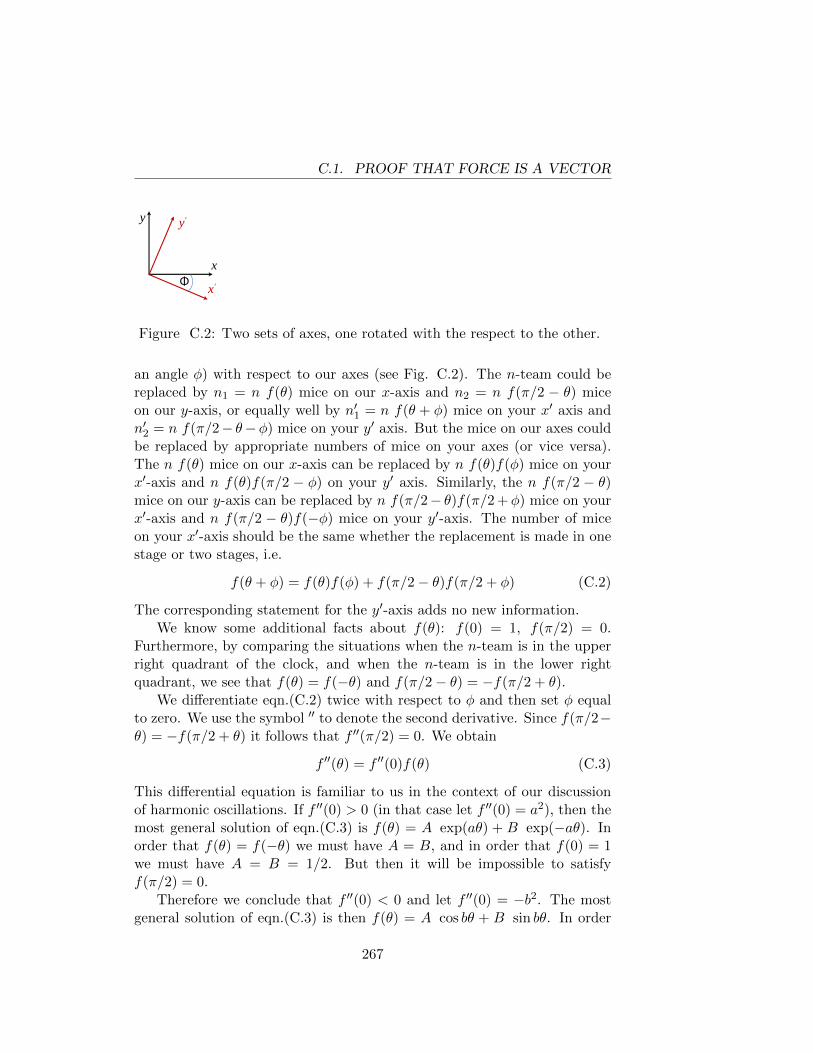
C.1. PROOF THAT FORCE IS A VECTOR
y y'
x'
x
Φ
Figure C.2: Two sets of axes, one rotated with the respect to the other.
an angle φ) with respect to our axes (see Fig. C.2). The n-team could bereplaced by n1 = n f(θ) mice on our x-axis and n2 = n f(π/2 − θ) miceon our y-axis, or equally well by n′1 = n f(θ + φ) mice on your x′ axis andn′2 = n f(π/2− θ−φ) mice on your y′ axis. But the mice on our axes couldbe replaced by appropriate numbers of mice on your axes (or vice versa).The n f(θ) mice on our x-axis can be replaced by n f(θ)f(φ) mice on yourx′-axis and n f(θ)f(π/2 − φ) on your y′ axis. Similarly, the n f(π/2 − θ)mice on our y-axis can be replaced by n f(π/2− θ)f(π/2 +φ) mice on yourx′-axis and n f(π/2 − θ)f(−φ) mice on your y′-axis. The number of miceon your x′-axis should be the same whether the replacement is made in onestage or two stages, i.e.
f(θ + φ) = f(θ)f(φ) + f(π/2− θ)f(π/2 + φ) (C.2)
The corresponding statement for the y′-axis adds no new information.We know some additional facts about f(θ): f(0) = 1, f(π/2) = 0.
Furthermore, by comparing the situations when the n-team is in the upperright quadrant of the clock, and when the n-team is in the lower rightquadrant, we see that f(θ) = f(−θ) and f(π/2− θ) = −f(π/2 + θ).
We differentiate eqn.(C.2) twice with respect to φ and then set φ equalto zero. We use the symbol ′′ to denote the second derivative. Since f(π/2−θ) = −f(π/2 + θ) it follows that f ′′(π/2) = 0. We obtain
f ′′(θ) = f ′′(0)f(θ) (C.3)
This differential equation is familiar to us in the context of our discussionof harmonic oscillations. If f ′′(0) > 0 (in that case let f ′′(0) = a2), then themost general solution of eqn.(C.3) is f(θ) = A exp(aθ) + B exp(−aθ). Inorder that f(θ) = f(−θ) we must have A = B, and in order that f(0) = 1we must have A = B = 1/2. But then it will be impossible to satisfyf(π/2) = 0.
Therefore we conclude that f ′′(0) < 0 and let f ′′(0) = −b2. The mostgeneral solution of eqn.(C.3) is then f(θ) = A cos bθ + B sin bθ. In order
267
C.1. PROOF THAT FORCE IS A VECTOR
that f(θ) = −f(θ) and f(0) = 1 we must have A = 1 and B = 0. In orderthat f(π/2) = 0 we must have b = 1, 3, 5, ... The odd integers greater than1 may be eliminated by the obvious (surely!) requirement that f(θ) ≥ 0for 0 ≤ θ ≤ π/2. Thus f(θ) = cos θ, which proves that force has all thecharacteristics of a vector. In particular, if two teams (each represented byan arrow) are pulling on the same point, they are equivalent to a single teamrepresented by the arrow which is the vector sum of the two arrows.
268
Appendix D
Appendix D
D.1 Equivalence of Acceleration of Axes and aFictional Gravitational Force
We provide here a proof for the addition of a fictional gravitational force toexplain the motion of a particle in a non-inertial frame when the accelerationof the frame can be determined relative to an inertial frame.
PROOF: If the axes of the inertial frame are ijk and axes attached to the(accelerating) box are i′j′k′, and the primed axes are non-rotating withrespect to the unprimed axes and have acceleration ~A relative to theunprimed axes, then a particle which has acceleration ~a′ relative tothe primed axes has acceleration ~a′ + ~A relative to the inertial frame.The equation of motion of the particle is ~F = m(~a′ + ~A), where ~F isthe total force acting on the particle. We can rewrite this as ~F ′ = m~a′,where ~F ′ is the sum of the real force ~F and the fictional force −m~A.Q.E.D.
269
D.1. EQUIVALENCE OF ACCELERATION OF AXES AND AFICTIONAL GRAVITATIONAL FORCE
270
Appendix E
Appendix E
E.1 Developing Your Problem-Solving Skills: Help-ful(?) Suggestions
A Dialogue: S = student P = professor or instructor
S: I understand the principles but have trouble with many of the problems.Is there some systematic method, something like a computer programor a set of rules, for approaching a problem and solving it withoutgoing up a bunch of blind alleys? When you solve a problem on theblackboard, you proceed in a straight line from the problem to thesolution. At each stage you seem to know which principle is relevant,and how to turn that principle into a useful equation. Do I have tosolve a thousand problems and make several thousand mistakes beforeI become pretty good at this game?
P: That would definitely be a good idea if you have enough time and pa-tience, but you still won’t become proficient unless you learn fromyour mistakes. Roughly speaking (and omitting discussion of embar-rassments like arithmetic errors and not knowing the difference be-tween the sine and the cosine), there are two kinds of errors: errorsof commission and errors of omission. A catalogue, even if edited toinclude only interesting (i.e. instructive) errors, would be quite volu-minous.
Some examples of errors of commission would be to write ~F = m~ain a non-inertial (illegal) frame (e.g. to measure ~a with respect to
271
E.1. DEVELOPING YOUR PROBLEM-SOLVING SKILLS:HELPFUL(?) SUGGESTIONS
axes attached to a rotating merry-go-round), or, when describing themotion of a pendulum, to use a kinematic formula which is applicableonly to the motion of an object moving with constant acceleration.
An error of omission would be to omit a useful force or torque equa-tion, or to omit important kinematic information, such as the relationbetween the velocities of various parts of a pulley system. In eithercase the number of unknown quantities will exceed the number ofequations.
S: Well, you haven’t really told me how to improve my proficiency, exceptby watching your elegant solutions on the blackboard.
P: Be that as it may, you have taught me something about the quality ofmy teaching. Maybe I should give back my teaching prize, which wasprobably based on my avuncular charm plus my skill in quickly solvingfreshman mechanics problems. Evidently, I haven’t adequately shownyou how I organize my thinking about a problem before I write downany equations. Of course, experience with similar problems is helpful,but I think there is something here which can be taught.
Before you write down any equations, you should understand howmany unknown quantities there are in a problem, and should have aclear program for constructing a set of equations, based on Newton’sLaws and/or kinematic constraints, which are sufficient to determinethe values of those quantities. It may be useful to write down a conciselist of the steps of the program, or, with experience , you can hold theprogram in your head. Of course, you may have found several distinctprograms, and, if time permits, you should execute each of them. Ifthey don’t all yield the same answers, it is important to identify theerror(s). Learning will surely occur.
S: It seems you’ve done most of the talking.
P: That’s my specialty. But you’ve got to do most of the thinking.
272
Appendix
PREFACE TO SOLUTIONSMANUAL
This instructor’s manual has complete solutions to problems for the open-source textbook “Classical Mechanics: A Critical Introduction” by ProfessorMichael Cohen. Students are strongly urged to solve the problems beforelooking at the solutions.
The responsibility for errors rests with me and I would appreciate beingnotified of any errors found in the solutions manual.
Sincerely,
Larry GladneyDepartment of Physics and AstronomyUniversity of PennsylvaniaPhiladelphia, PA 19104-6396email: [email protected]
273
274
Appendix 1
KINEMATICS
1.1 Kinematics Problems Solutions
1.1.1 One-Dimensional Motion
1.1. (a) We find the area under the velocity vs. time graph to get thedistance traveled (i.e. the displacement). From Fig.Soln:1.1 wecan easily divide the area under the velocity vs. time plot into 3areas. Adding the areas gives the answer.
area 1 = 12(35 m/s− 10 m/s)(10 s− 0) = 125 m
area 2 = (10 m/s− 0)(20 s− 0) = 200 m
area 3 = (10 m/s− 0)(40 s− 20 s) = 200 m
total distance from t = 0 to t = 40 = 525 m
(b) The acceleration is just the slope of the velocity vs. time graph,so
a =v(t = 60)− v(t = 40)
60 s− 40 s= −0.5 m/s2
(c) We need the total displacement of the car at t = 60 seconds.
area t = 40→ 60 =1
2(60 s− 40 s)(10 m/s− 0) = 100 m
275
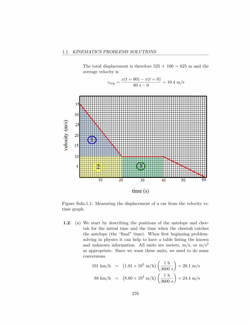
1.1. KINEMATICS PROBLEMS SOLUTIONS
The total displacement is therefore 525 + 100 = 625 m and theaverage velocity is
vavg =x(t = 60)− x(t = 0)
60 s− 0= 10.4 m/s
Figure Soln:1.1: Measuring the displacement of a car from the velocity vs.time graph.
1.2. (a) We start by describing the positions of the antelope and chee-tah for the initial time and the time when the cheetah catchesthe antelope (the “final” time). When first beginning problem-solving in physics it can help to have a table listing the knownand unknown information. All units are meters, m/s, or m/s2
as appropriate. Since we want these units, we need to do someconversions.
101 km/h =(1.01× 10⁵ m/h
)( 1 h
3600 s
)= 28.1 m/s
88 km/h =(8.80× 10⁴ m/h
)( 1 h
3600 s
)= 24.4 m/s
276
1.1. KINEMATICS PROBLEMS SOLUTIONS
cheetah antelope
initial position x0c = 0. x0a = 50.0final position xc =? xa = xc
initial velocity v0c = 28.1 v0a = 24.4final velocity vc = 28.1 va = 24.4
acceleration ac = 0. aa = ac = 0
The problem specifies that we get the time at which the positionsof the cheetah and antelope are the same. Using eqn.( 1.11c), wehave
xc = xa
x0c + v0ct = x0a + v0at⇒t =
x0a
v0c − v0a
=50.0 m
(28.1− 24.4) m/s
t = 13.5 s
The distance traveled by the cheetah is
xc = v0ct = (28.1 m/s)(13.5 s) = 379 m.
(b) The situation is the same as for part a. except that now the start-ing position of the antelope is unknown and the time of captureis t = 20 s. Thus,
xc = xa
x0c + v0ct = v0ct = x0a + v0at⇒x0a = (v0c − v0a)t
= (28.1 m/s− 24.4 m/s)(20.0 s) = 74.0 m
1.3. (a) We do not know the height of the bottom of the window abovethe release point of the throw but this does not matter as theacceleration is constant and known and the time of travel acrossa known distance is also known. Therefore, if v0 is the speed ofthe ball as it passes the bottom of the window, t is the time forthe ball to cross from the bottom to the top of the window, y0 isthe position of the bottom of the window, and y1 is the position
277
1.1. KINEMATICS PROBLEMS SOLUTIONS
of the top of the window, then
y1 = y0 + v0t− 12gt2 ⇒
v0 =(y1 − y0) + (1/2)gt2
t
=(3.00 m) + (1/2)(9.80 m/s2)(0.400 s)2
0.400 sv0 = 9.46 m/s
This gives us the position of the top of the ball’s flight since thefinal speed is zero. So,
v2f = 0 = v2
0 − 2g(yf − y0)⇒
yf − y0 =v2
0
2g=
(9.46 m/s)2
2(9.80 m/s2)= 4.57 m
Therefore the maximum height above the top of the window is
yf − y1 = (4.57− 3.00) m = 1.57 m
(b) The speed of the ball when it first reaches the top of the windowis
v1 = v0 − gt = 9.46 m/s− (9.80 m/s2)(0.400 s) = 5.54 m/s
The time interval, ∆t, between passing the top of the window onthe way up (v1) and on the way down (we call this vdown) is
vdown = vup − g∆t⇒
∆t =−v1 − v1
−g
=−2(5.54 m/s2)
−9.80 m/s2
∆t = 1.13 s
1.4. We solve the problem in a reference frame which has the velocity whichthe elevator had when the ball was released (we assume that the balldoes not hit the ceiling of the elevator). If we take t=0 at the instantwhen the ball was released and denote the vertical coordinate by y,then yfloor = 1
2A t2 and yball = v0t − 1
2gt2 . The height of the ball
278
1.1. KINEMATICS PROBLEMS SOLUTIONS
above the floor is yb − yf = v0t− 12(g +A)t2. This is maximum when
t = v0/(g +A) and has the value hmax = v20/2(g +A).
We see that the maximum height above the floor which the ball reachesis the same as the maximum height it would reach if it were projectedupward with velocity v0 in a non-accelerating box on a planet where theacceleration of gravity is g+A (rather than g). We shall see (Example3.2) that the upward force which the floor exerts on a person of massm in an accelerating elevator (this is the force which a scale measures)is m(g + A), which is what the scale would read if the elevator werenot accelerating but were on a planet where the acceleration of gravityis (g +A).
Quite generally (see Appendix D), we can show that if a box hasacceleration A (and is not rotating) relative to an inertial frame (i.e. aframe in which Newton’s laws hold), we can treat axes attached to thebox as though they were an inertial frame, provided that when we listthe forces acting on an object in the box we add to the list a fictionalforce −mA. This extra “force” has the same form as the gravitationalforce mg. We call it “fictional” because it is not due to the action ofany identifiable piece of matter.
1.5. (a) The walkway is less than 200 m in length. If we call the lengthof the walkway x, then for the race to end in a tie, Miriam mustrun the distance 200−x m at a rate of 6 m/s so that sum of timeon the walkway (determined by her speed of 6 + 2 = 8 m/s) andoff the walkway equals Alison’s 200 m divided by her constantspeed of 7 m/s. So,
200 m
7.00 m/s=
x
8.00 m/s+
200 m− x6.00 m/s
⇒
A common factor for the numbers 6, 7, and 8 is 168 (7 · 8 · 3) somultiply through by this factor (i.e. 168 m/s) and solve for x.
24(200 m) = 21x+ 28(200 m− x)⇒7x = (28− 24)(200 m)⇒x = 114 m
279
1.1. KINEMATICS PROBLEMS SOLUTIONS
(b) Now we must look at the times separately for Alison and Miriam.
tMiriam =200 m
6.00 m/s= 33.3 s
tAlison =114 m
(7.00− 2.00) m/s+
(200− 114) m
7.00 m/s= 35.1 s
Miriam wins the race.
1.1.2 Two and Three Dimensional Motion
1.6. We make use of equations from the chapter.
(a) We make use of eqn.( 1.15).
~v(t) =d~r
dt= [(4t− 7)i− 2tj] m/s⇒
~v(t = 2) = [i− 4j] m/s
(b)
~a(t) =d~v
dt= [4i− 2j] m/s2 = ~a(t = 5 s)
(c) The average velocity is given by eqn.(1.1).
vav =~r(t = 3)− ~r(t = 1)
3− 1
=[(18− 21)− (2− 7)]i− (9− 1)j
2m/s
vav = (i− 4j) m/s
1.7. Note that the slope of the hill can be described in terms of
− tan θ1 =yhxh
with θ1 = 10.0◦ and (xh, yh) being coordinates of the hill surface. Weadopt the usual convention of up being the +y direction so we needto have the angle θ1 of the hill as directed below the horizontal. Theposition of the skier as a function of time, assuming the takeoff pointis set as coordinate (0,+6.00 m), is
xs = v0 cos θ2t
ys = 6.00 m + v0 sin θ2t− 12gt2
280
1.1. KINEMATICS PROBLEMS SOLUTIONS
Eliminating t from the two equations gives
ys = 6.00 m + xs tan θ2 −g
2
x2s
(v0 cos θ2)2
The definition of “landing” is to have xs = xh simultaneously withys = yh. Let’s just drop the subscripts then and define x as horizontaldistance from the takeoff point. Then
y = −x tan θ1 = 6.00 m + x tan θ2 −gx2
2(v0 cos θ2)2⇒
0 = 6.00 m + x (tan 15.0◦ + tan 10.0◦)−(9.80 m/s2
)x2
2 (30.0 m/s · cos 15.0◦)2
= 6.00 m + x(0.44428)−(5.83534× 10⁻³ m−1
)x2 ⇒
x =−0.44428±
√0.197381 + 4(0.00583534)(6.00)
2 (−0.00583534 m−1)
= 87.8 m
Note that the other root from the square root gives the answer cor-responding to where the trajectory would start on the incline if theramp were not present.
1.8. The period is derived from the speed of a point on the outer rim andthis is in turn determined by the centripetal acceleration value. If r isthe radius to the outer rim and the period is τ , then
a =g
5=
v2
r⇒
v =
√rg
5
τ =2πr
v= 2π
√5r
g
= 2(3.141593)
√5(1000 m)
9.81 m/s2
τ = 142 s
1.9. The radius can be derived from the definition of centripetal accelera-
281
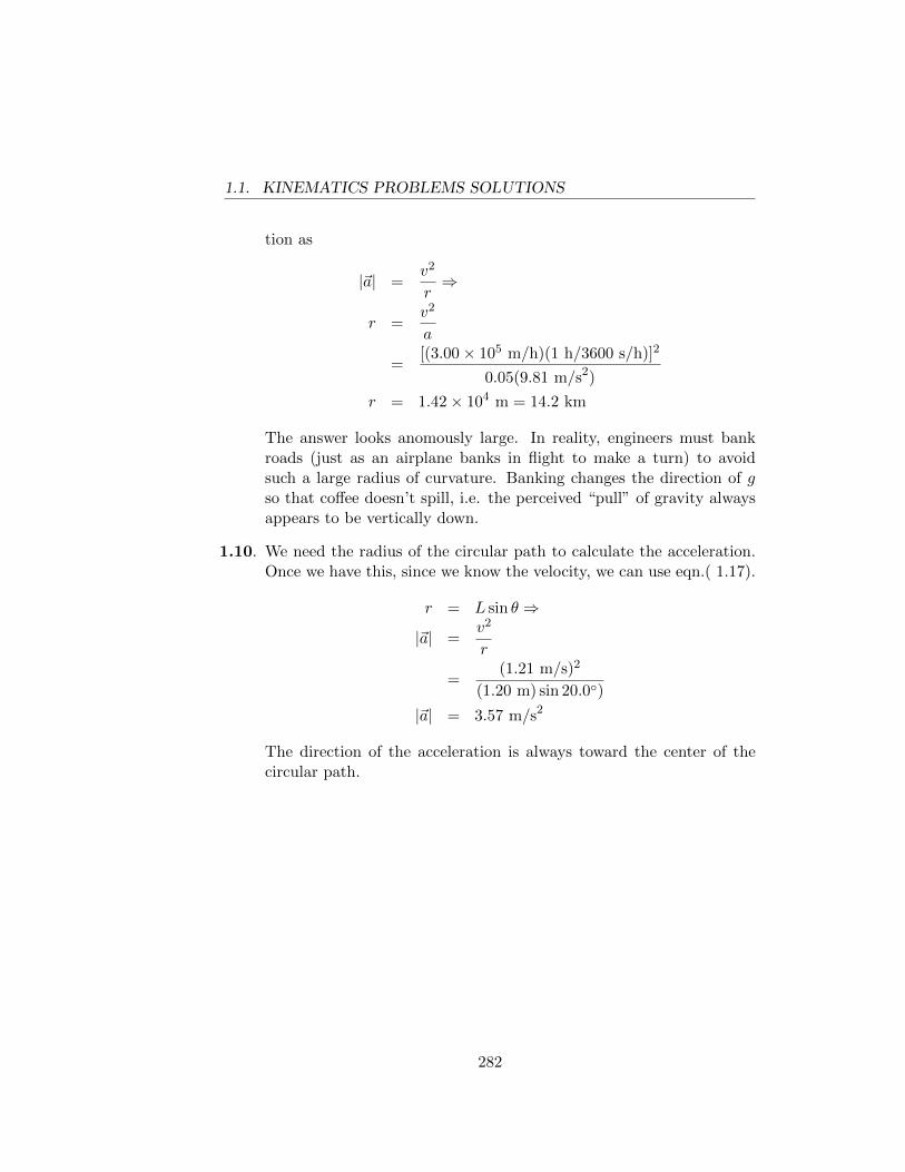
1.1. KINEMATICS PROBLEMS SOLUTIONS
tion as
|~a| =v2
r⇒
r =v2
a
=[(3.00× 10⁵ m/h)(1 h/3600 s/h)]2
0.05(9.81 m/s2)
r = 1.42× 10⁴ m = 14.2 km
The answer looks anomously large. In reality, engineers must bankroads (just as an airplane banks in flight to make a turn) to avoidsuch a large radius of curvature. Banking changes the direction of gso that coffee doesn’t spill, i.e. the perceived “pull” of gravity alwaysappears to be vertically down.
1.10. We need the radius of the circular path to calculate the acceleration.Once we have this, since we know the velocity, we can use eqn.( 1.17).
r = L sin θ ⇒
|~a| =v2
r
=(1.21 m/s)2
(1.20 m) sin 20.0◦)
|~a| = 3.57 m/s2
The direction of the acceleration is always toward the center of thecircular path.
282
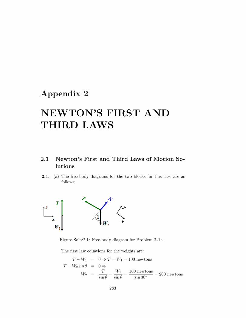
Appendix 2
NEWTON’S FIRST ANDTHIRD LAWS
2.1 Newton’s First and Third Laws of Motion So-lutions
2.1. (a) The free-body diagrams for the two blocks for this case are asfollows:
Figure Soln:2.1: Free-body diagram for Problem 2.1a.
The first law equations for the weights are:
T −W1 = 0⇒ T = W1 = 100 newtons
T −W2 sin θ = 0⇒
W2 =T
sin θ=
W1
sin θ=
100 newtons
sin 30◦= 200 newtons
283
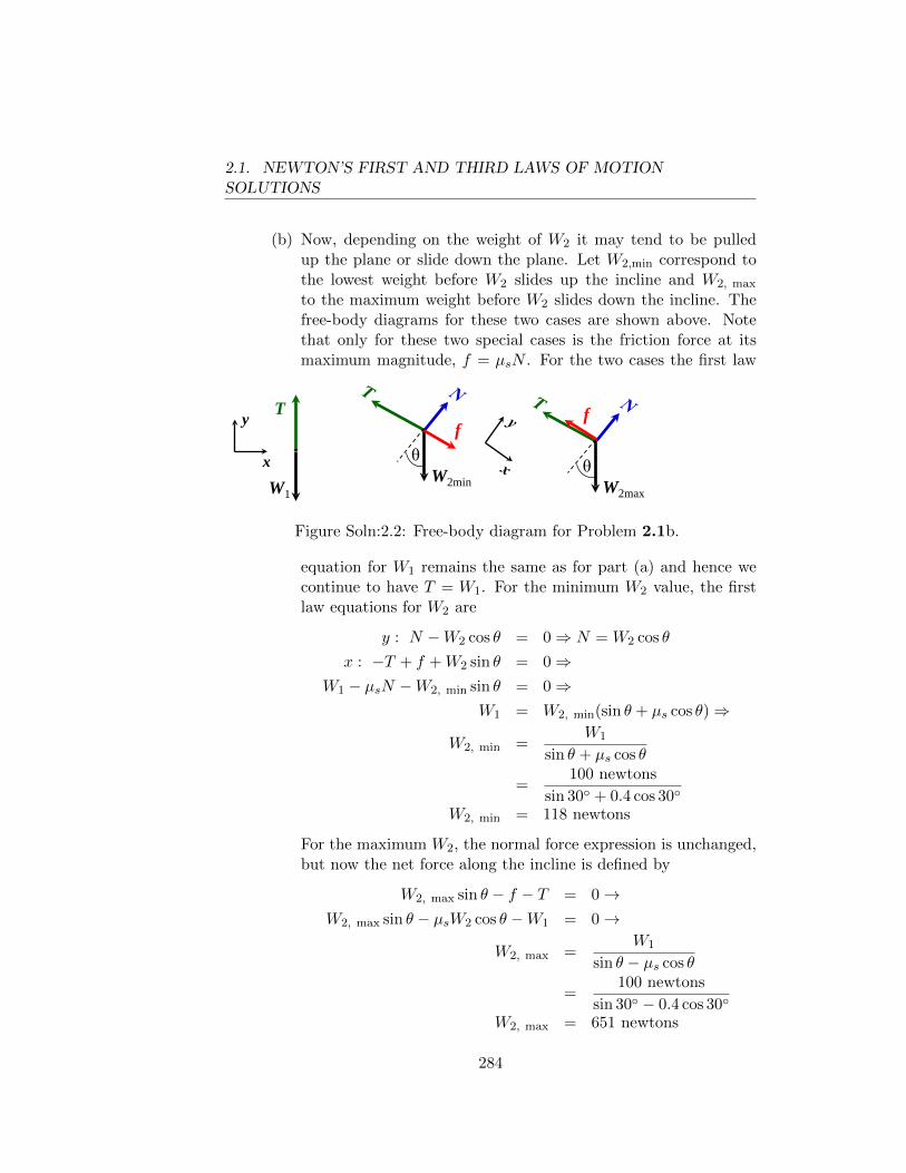
2.1. NEWTON’S FIRST AND THIRD LAWS OF MOTIONSOLUTIONS
(b) Now, depending on the weight of W2 it may tend to be pulledup the plane or slide down the plane. Let W2,min correspond tothe lowest weight before W2 slides up the incline and W2, max
to the maximum weight before W2 slides down the incline. Thefree-body diagrams for these two cases are shown above. Notethat only for these two special cases is the friction force at itsmaximum magnitude, f = µsN . For the two cases the first law
W1
θ
T
W2min
y
x θ W2max
f f
Figure Soln:2.2: Free-body diagram for Problem 2.1b.
equation for W1 remains the same as for part (a) and hence wecontinue to have T = W1. For the minimum W2 value, the firstlaw equations for W2 are
y : N −W2 cos θ = 0⇒ N = W2 cos θ
x : −T + f +W2 sin θ = 0⇒W1 − µsN −W2, min sin θ = 0⇒
W1 = W2, min(sin θ + µs cos θ)⇒
W2, min =W1
sin θ + µs cos θ
=100 newtons
sin 30◦ + 0.4 cos 30◦
W2, min = 118 newtons
For the maximum W2, the normal force expression is unchanged,but now the net force along the incline is defined by
W2, max sin θ − f − T = 0→W2, max sin θ − µsW2 cos θ −W1 = 0→
W2, max =W1
sin θ − µs cos θ
=100 newtons
sin 30◦ − 0.4 cos 30◦
W2, max = 651 newtons
284
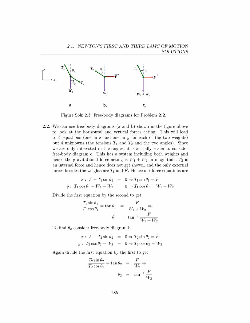
2.1. NEWTON’S FIRST AND THIRD LAWS OF MOTIONSOLUTIONS
θ2
W1 W2
F
θ1 T1 T2 θ2 y
x T2
F
W1 + W2
θ1 T1
a. b. c.
Figure Soln:2.3: Free-body diagrams for Problem 2.2.
2.2. We can use free-body diagrams (a and b) shown in the figure aboveto look at the horizontal and vertical forces acting. This will leadto 4 equations (one in x and one in y for each of the two weights)but 4 unknowns (the tensions T1 and T2 and the two angles). Sincewe are only interested in the angles, it is actually easier to considerfree-body diagram c. This has a system including both weights andhence the gravitational force acting is W1 + W2 in magnitude, ~T2 isan internal force and hence does not get shown, and the only externalforces besides the weights are ~T1 and ~F . Hence our force equations are
x : F − T1 sin θ1 = 0⇒ T1 sin θ1 = F
y : T1 cos θ1 −W1 −W2 = 0⇒ T1 cos θ1 = W1 +W2
Divide the first equation by the second to get
T1 sin θ1
T1 cos θ1= tan θ1 =
F
W1 +W2⇒
θ1 = tan−1 F
W1 +W2
To find θ2 consider free-body diagram b.
x : F − T2 sin θ2 = 0⇒ T2 sin θ2 = F
y : T2 cos θ2 −W2 = 0⇒ T2 cos θ2 = W2
Again divide the first equation by the first to get
T2 sin θ2
T2 cos θ2= tan θ2 =
F
W2⇒
θ2 = tan−1 F
W2
285
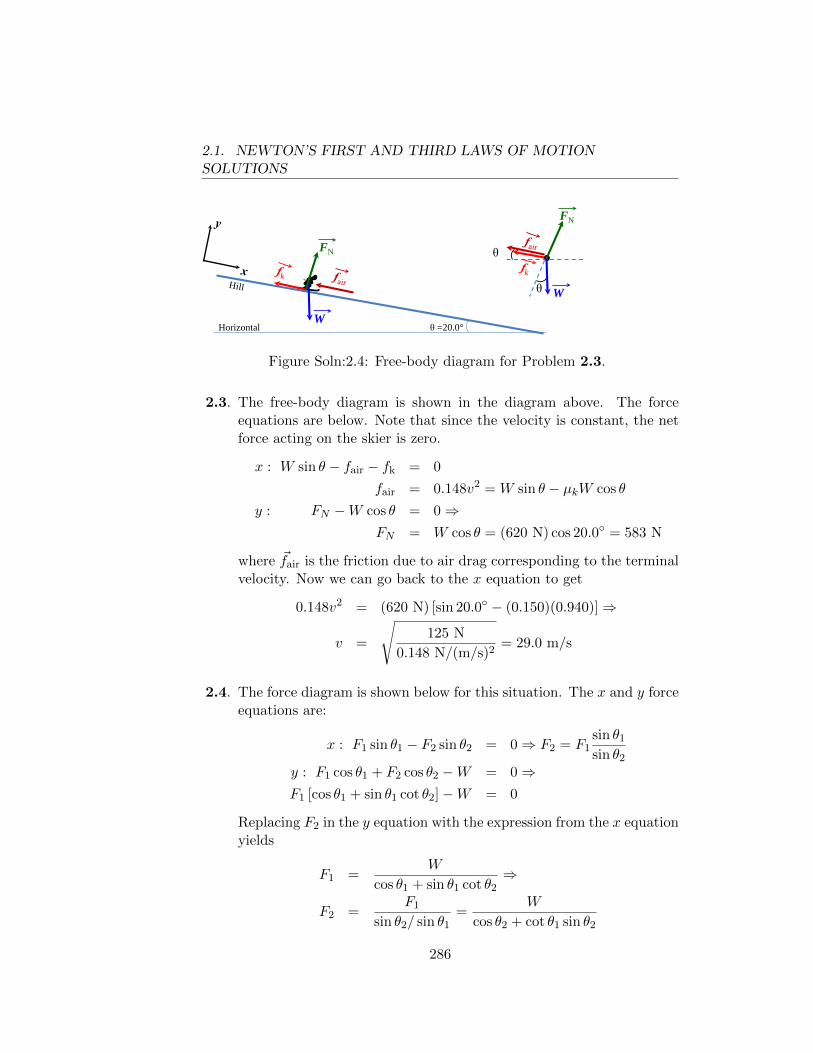
2.1. NEWTON’S FIRST AND THIRD LAWS OF MOTIONSOLUTIONS
θ =20.0° Horizontal W
θ
W
FN
FN
θ
Figure Soln:2.4: Free-body diagram for Problem 2.3.
2.3. The free-body diagram is shown in the diagram above. The forceequations are below. Note that since the velocity is constant, the netforce acting on the skier is zero.
x : W sin θ − fair − fk = 0
fair = 0.148v2 = W sin θ − µkW cos θ
y : FN −W cos θ = 0⇒FN = W cos θ = (620 N) cos 20.0◦ = 583 N
where ~fair is the friction due to air drag corresponding to the terminalvelocity. Now we can go back to the x equation to get
0.148v2 = (620 N) [sin 20.0◦ − (0.150)(0.940)]⇒
v =
√125 N
0.148 N/(m/s)2= 29.0 m/s
2.4. The force diagram is shown below for this situation. The x and y forceequations are:
x : F1 sin θ1 − F2 sin θ2 = 0⇒ F2 = F1sin θ1
sin θ2
y : F1 cos θ1 + F2 cos θ2 −W = 0⇒F1 [cos θ1 + sin θ1 cot θ2]−W = 0
Replacing F2 in the y equation with the expression from the x equationyields
F1 =W
cos θ1 + sin θ1 cot θ2⇒
F2 =F1
sin θ2/ sin θ1=
W
cos θ2 + cot θ1 sin θ2
286
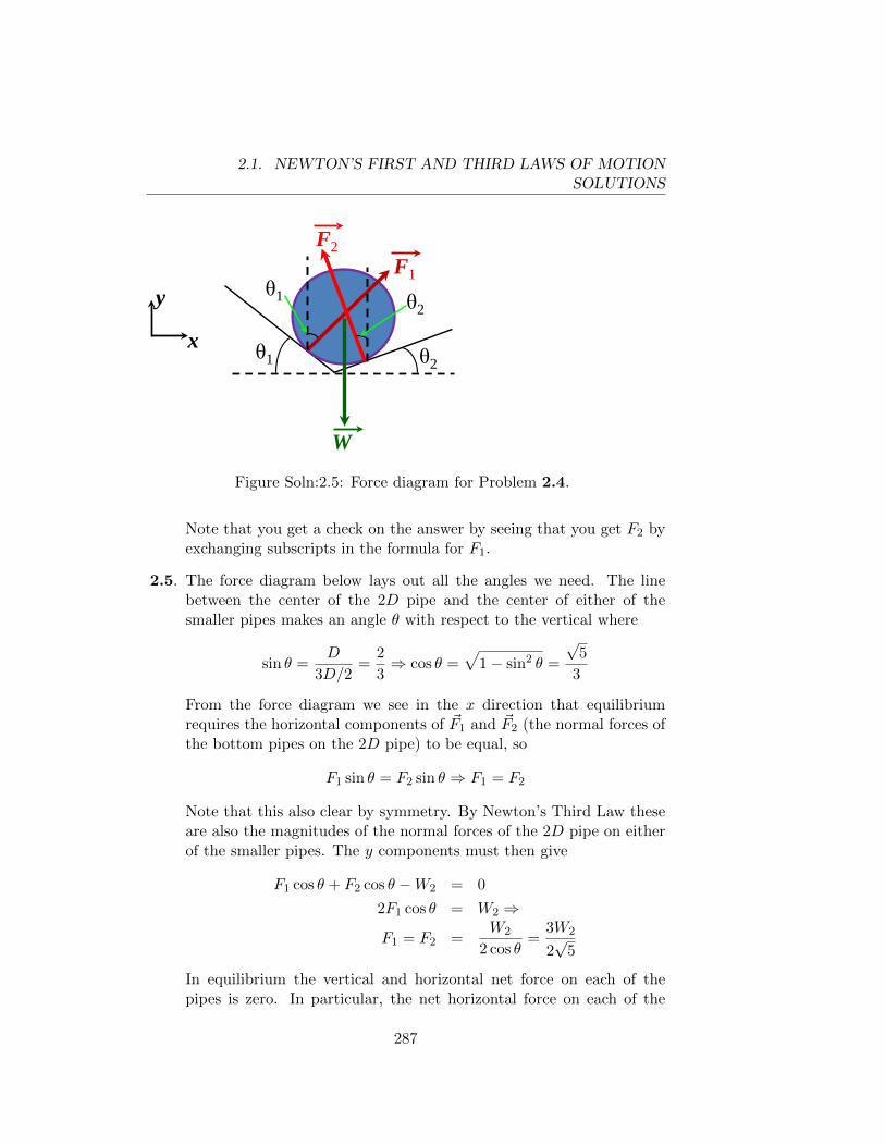
2.1. NEWTON’S FIRST AND THIRD LAWS OF MOTIONSOLUTIONS
θ2 θ1
W
θ2 θ1
F1 F2
x
y
Figure Soln:2.5: Force diagram for Problem 2.4.
Note that you get a check on the answer by seeing that you get F2 byexchanging subscripts in the formula for F1.
2.5. The force diagram below lays out all the angles we need. The linebetween the center of the 2D pipe and the center of either of thesmaller pipes makes an angle θ with respect to the vertical where
sin θ =D
3D/2=
2
3⇒ cos θ =
√1− sin2 θ =
√5
3
From the force diagram we see in the x direction that equilibriumrequires the horizontal components of ~F1 and ~F2 (the normal forces ofthe bottom pipes on the 2D pipe) to be equal, so
F1 sin θ = F2 sin θ ⇒ F1 = F2
Note that this also clear by symmetry. By Newton’s Third Law theseare also the magnitudes of the normal forces of the 2D pipe on eitherof the smaller pipes. The y components must then give
F1 cos θ + F2 cos θ −W2 = 0
2F1 cos θ = W2 ⇒
F1 = F2 =W2
2 cos θ=
3W2
2√
5
In equilibrium the vertical and horizontal net force on each of thepipes is zero. In particular, the net horizontal force on each of the
287
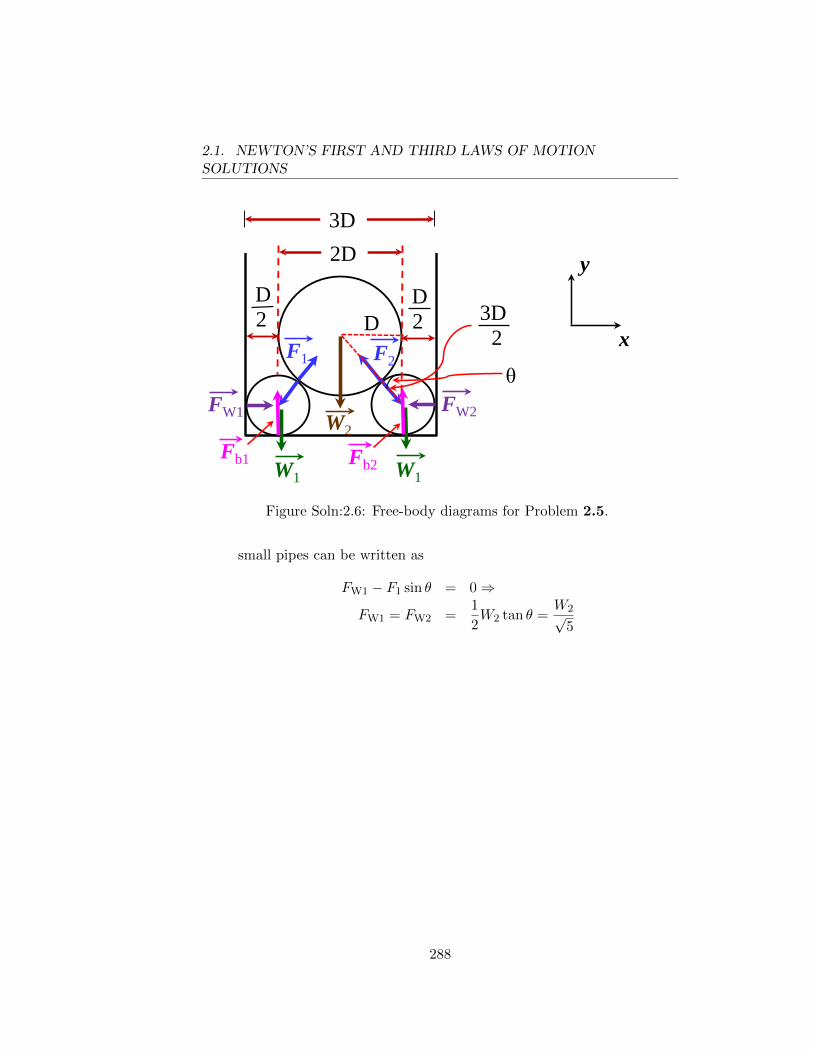
2.1. NEWTON’S FIRST AND THIRD LAWS OF MOTIONSOLUTIONS
2D 3D
W1 W1
W2
D 2
D 2
F1 F2
FW1 FW2
D 3D 2
θ
Fb1 Fb2
y
x
Figure Soln:2.6: Free-body diagrams for Problem 2.5.
small pipes can be written as
FW1 − F1 sin θ = 0⇒
FW1 = FW2 =1
2W2 tan θ =
W2√5
288
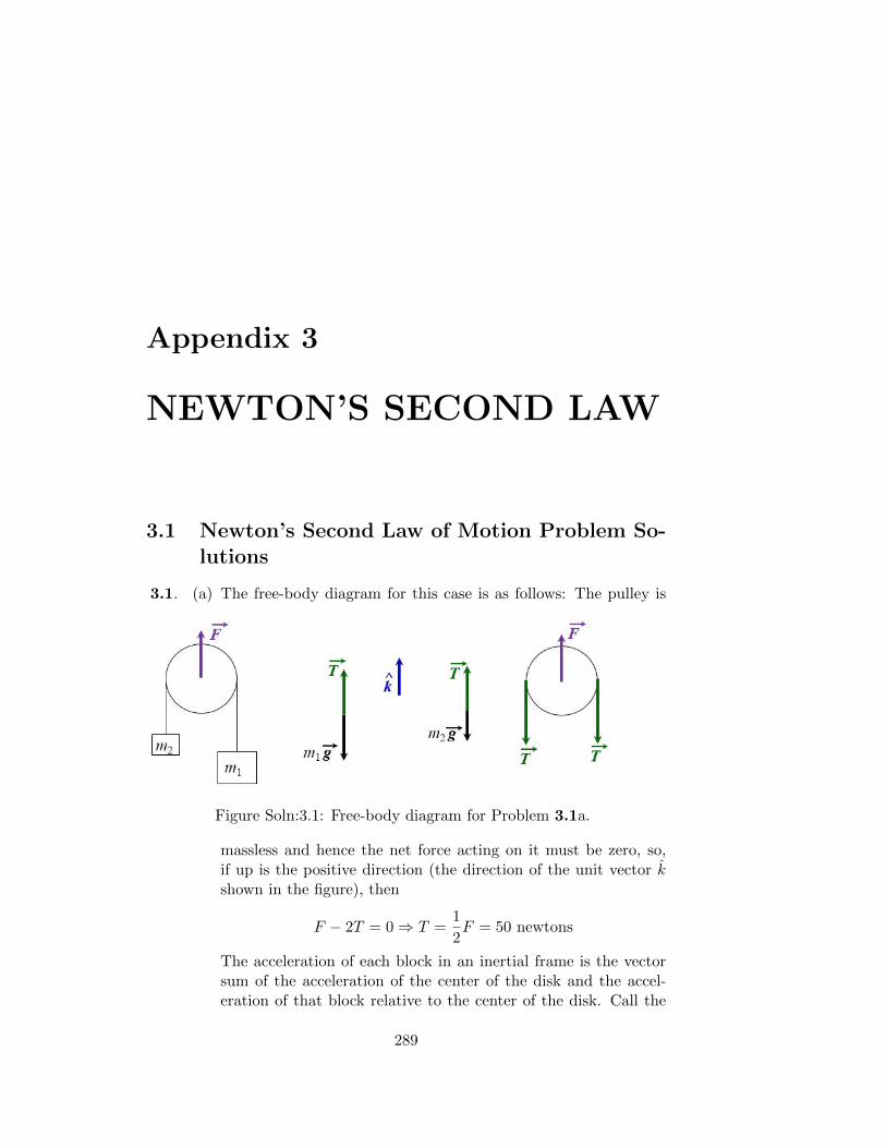
Appendix 3
NEWTON’S SECOND LAW
3.1 Newton’s Second Law of Motion Problem So-lutions
3.1. (a) The free-body diagram for this case is as follows: The pulley is
Figure Soln:3.1: Free-body diagram for Problem 3.1a.
massless and hence the net force acting on it must be zero, so,if up is the positive direction (the direction of the unit vector kshown in the figure), then
F − 2T = 0⇒ T =1
2F = 50 newtons
The acceleration of each block in an inertial frame is the vectorsum of the acceleration of the center of the disk and the accel-eration of that block relative to the center of the disk. Call the
289
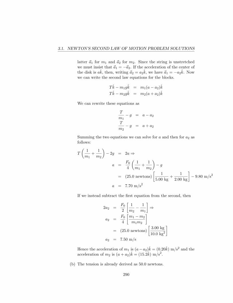
3.1. NEWTON’S SECOND LAW OF MOTION PROBLEM SOLUTIONS
latter ~a1 for m1 and ~a2 for m2. Since the string is unstretchedwe must insist that ~a1 = −~a2. If the acceleration of the center ofthe disk is ak, then, writing ~a2 = a2k, we have ~a1 = −a2k. Nowwe can write the second law equations for the blocks.
T k −m1gk = m1(a− a2)k
T k −m2gk = m2(a+ a2)k
We can rewrite these equations as
T
m1− g = a− a2
T
m2− g = a+ a2
Summing the two equations we can solve for a and then for a2 asfollows:
T
(1
m1+
1
m2
)− 2g = 2a⇒
a =F0
4
(1
m1+
1
m2
)− g
= (25.0 newtons)
[1
5.00 kg+
1
2.00 kg
]− 9.80 m/s2
a = 7.70 m/s2
If we instead subtract the first equation from the second, then
2a2 =F0
2
[1
m2− 1
m1
]⇒
a2 =F0
4
[m1 −m2
m1m2
]= (25.0 newtons)
[3.00 kg
10.0 kg2
]a2 = 7.50 m/s
Hence the acceleration of m1 is (a−a2)k = (0.20k) m/s2 and theacceleration of m2 is (a+ a2)k = (15.2k) m/s2.
(b) The tension is already derived as 50.0 newtons.
290
3.1. NEWTON’S SECOND LAW OF MOTION PROBLEM SOLUTIONS
3.2. We solve the problem in an inertial frame which has the velocity whichthe elevator had when the ball was released (we assume that the balldoes not hit the ceiling of the elevator). If we take t = 0 at the instantwhen the ball was released and denote the vertical coordinate by y,then yfloor = 1
2At2 and yball = v0t− 1
2gt2. The height of the ball above
the floor is yball − yfinal = v0t − 12(g + A)t2. This is maximum when
t = v0/(g +A) and has the value
hmax =v2
0
2(g +A).
We see that the maximum height above the floor which the ball reachesis the same as the maximum height it would reach if it were projectedupward with velocity v0 in a non-accelerating box on a planet wherethe acceleration of gravity is ~g + ~A (rather than ~g where ~g = −gkwhere k points vertically upward from the earth). We have alreadyseen (Example 3.2) that the upward force which the floor exerts on aperson of mass m in an accelerating elevator (this is the force whicha scale measures) is m(g + A), which is what the scale would readif the elevator were not accelerating but were on a planet where theacceleration of gravity is (~g + ~A).
Quite generally, we can show that if a box has acceleration ~A (and isnot rotating) relative to an inertial frame, we can treat axes attachedto the box as though they were an inertial frame, provided that whenwe list the forces acting on an object in the box we add to the lista fictional force −m~A. This extra “force” has the same form as thegravitational force m~g . We call it “fictional” because it is not due tothe action of any identifiable piece of matter.
PROOF: If the axes of the inertial frame are ijk and axes attached tothe box are i′j′k′, then a particle which has acceleration ~a′ relative tothe primed axes has acceleration ~a′ + ~A relative to the inertial frame.The equation of motion of the particle is ~F = m(~a′ + ~A), where ~F isthe total force acting on the particle. We can rewrite this as ~F ′ = m~a′,where ~F ′ is the sum of the real force ~F and the fictional force −m~A.Q.E.D.
3.3. (a) If the board is not slipping then the acceleration of the boy inan inertial frame is also ~a. The boy must therefore have force~F = mboy~a acting on him and he must exert a force of the samemagnitude on the board. The minimum acceleration of the boy
291
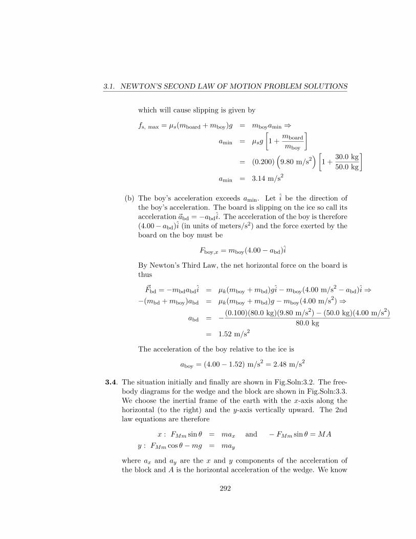
3.1. NEWTON’S SECOND LAW OF MOTION PROBLEM SOLUTIONS
which will cause slipping is given by
fs, max = µs(mboard +mboy)g = mboyamin ⇒
amin = µsg
[1 +
mboard
mboy
]= (0.200)
(9.80 m/s2
)[1 +
30.0 kg
50.0 kg
]amin = 3.14 m/s2
(b) The boy’s acceleration exceeds amin. Let i be the direction ofthe boy’s acceleration. The board is slipping on the ice so call itsacceleration ~abd = −abdi. The acceleration of the boy is therefore(4.00− abd)i (in units of meters/s2) and the force exerted by theboard on the boy must be
Fboy,x = mboy(4.00− abd)i
By Newton’s Third Law, the net horizontal force on the board isthus
~Fbd = −mbdabdi = µk(mboy +mbd)gi−mboy(4.00 m/s2 − abd)i⇒−(mbd +mboy)abd = µk(mboy +mbd)g −mboy(4.00 m/s2)⇒
abd = −(0.100)(80.0 kg)(9.80 m/s2)− (50.0 kg)(4.00 m/s2)
80.0 kg
= 1.52 m/s2
The acceleration of the boy relative to the ice is
aboy = (4.00− 1.52) m/s2 = 2.48 m/s2
3.4. The situation initially and finally are shown in Fig.Soln:3.2. The free-body diagrams for the wedge and the block are shown in Fig.Soln:3.3.We choose the inertial frame of the earth with the x-axis along thehorizontal (to the right) and the y-axis vertically upward. The 2ndlaw equations are therefore
x : FMm sin θ = max and − FMm sin θ = MA
y : FMm cos θ −mg = may
where ax and ay are the x and y components of the acceleration ofthe block and A is the horizontal acceleration of the wedge. We know
292
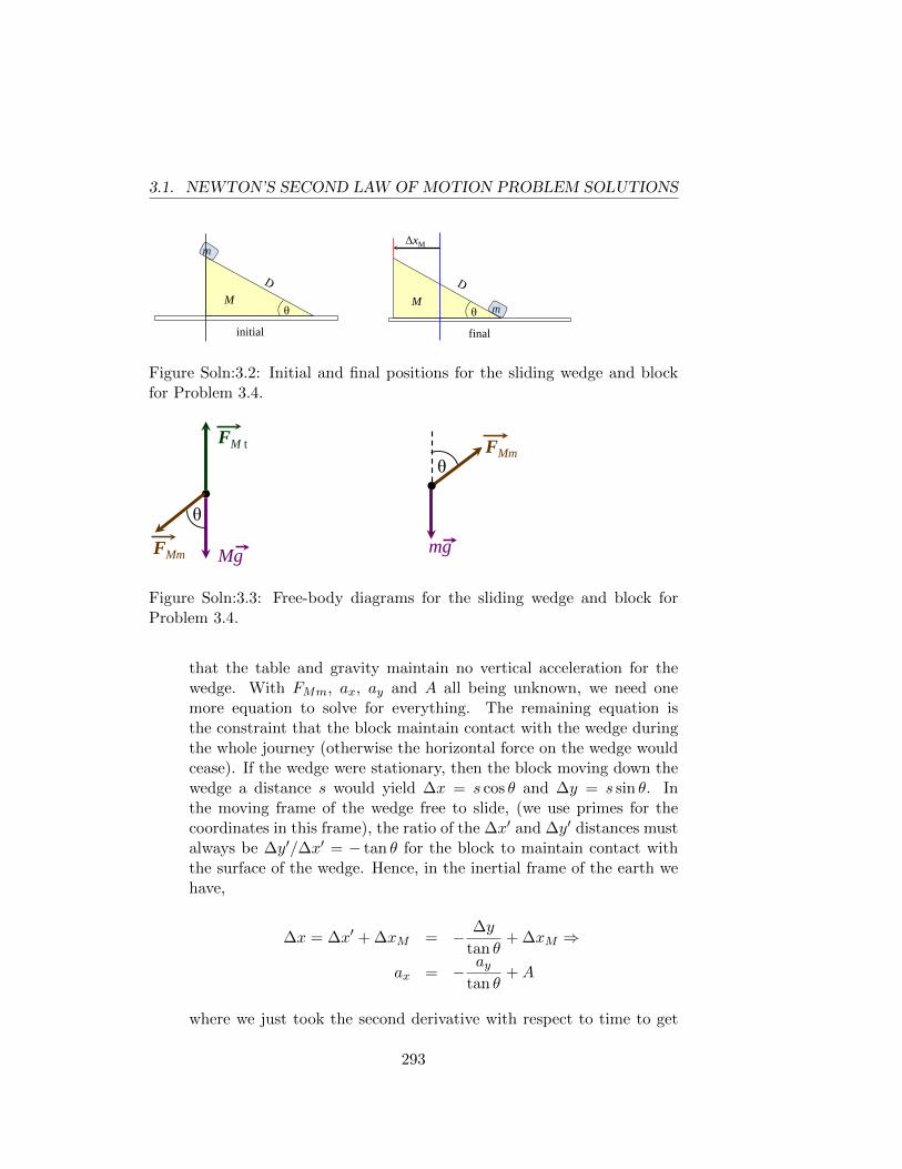
3.1. NEWTON’S SECOND LAW OF MOTION PROBLEM SOLUTIONS
m
θ M
initial final
θ M m
ΔxM
Mg
FM t
θ
FMm mg
FMm θ Figure Soln:3.2: Initial and final positions for the sliding wedge and block
for Problem 3.4.
m
θ M
initial final
θ M m
ΔxM
Mg
FM t
θ
FMm mg
FMm θ
Figure Soln:3.3: Free-body diagrams for the sliding wedge and block forProblem 3.4.
that the table and gravity maintain no vertical acceleration for thewedge. With FMm, ax, ay and A all being unknown, we need onemore equation to solve for everything. The remaining equation isthe constraint that the block maintain contact with the wedge duringthe whole journey (otherwise the horizontal force on the wedge wouldcease). If the wedge were stationary, then the block moving down thewedge a distance s would yield ∆x = s cos θ and ∆y = s sin θ. Inthe moving frame of the wedge free to slide, (we use primes for thecoordinates in this frame), the ratio of the ∆x′ and ∆y′ distances mustalways be ∆y′/∆x′ = − tan θ for the block to maintain contact withthe surface of the wedge. Hence, in the inertial frame of the earth wehave,
∆x = ∆x′ + ∆xM = − ∆y
tan θ+ ∆xM ⇒
ax = − aytan θ
+A
where we just took the second derivative with respect to time to get
293
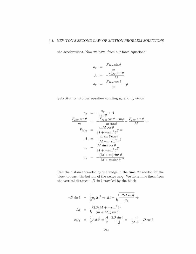
3.1. NEWTON’S SECOND LAW OF MOTION PROBLEM SOLUTIONS
the accelerations. Now we have, from our force equations
ax =FMm sin θ
m
A = −FMm sin θ
M
ay =FMm cos θ
m− g
Substituting into our equation coupling ax and ay yields
ax = − aytan θ
+A
FMm sin θ
m= −FMm cos θ −mg
m tan θ− FMm sin θ
M⇒
FMm =mM cos θ
M +m sin2 θg ⇒
A = − m sin θ cos θ
M +m sin2 θg
ax =M sin θ cos θ
M +m sin2 θg
ay = −(M +m) sin2 θ
M +m sin2 θg
Call the distance traveled by the wedge in the time ∆t needed for theblock to reach the bottom of the wedge xMf . We determine them fromthe vertical distance −D sin θ traveled by the block
−D sin θ =1
2ay∆t
2 ⇒ ∆t =
√−2D sin θ
ay⇒
∆t =
√2D(M +m sin2 θ)
(m+M)g sin θ
xMf =1
2A∆t2 =
A
2· 2D sin θ
|ay|= − m
M +mD cos θ
294
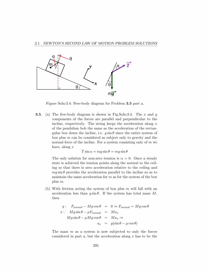
3.1. NEWTON’S SECOND LAW OF MOTION PROBLEM SOLUTIONS
θ mg
T
α m
x
y θ
α
θ
Figure Soln:3.4: Free-body diagram for Problem 3.5 part a.
3.5. (a) The free-body diagram is shown in Fig.Soln:3.4. The x and ycomponents of the forces are parallel and perpendicular to theincline, respectively. The string keeps the acceleration along xof the pendulum bob the same as the acceleration of the rectan-gular box down the incline, i.e. g sin θ since the entire system ofbox plus m can be considered as subject only to gravity and thenormal force of the incline. For a system consisting only of m wehave, along x
T sinα+mg sin θ = mg sin θ
The only solution for non-zero tension is α = 0. Once a steadystate is achieved the tension points along the normal to the ceil-ing so that there is zero acceleration relative to the ceiling andmg sin θ provides the acceleration parallel to the incline so as tomaintain the same acceleration for m as for the system of the boxplus m.
(b) With friction acting the system of box plus m will fall with anacceleration less than g sin θ. If the system has total mass M ,then
y : Fnormal −Mg cos θ = 0⇒ Fnormal = Mg cos θ
x : Mg sin θ − µFnormal = Max
Mg sin θ − µMg cos θ = Max ⇒ax = g(sin θ − µ cos θ)
The mass m as a system is now subjected to only the forcesconsidered in part a, but the acceleration along x has to be the
295
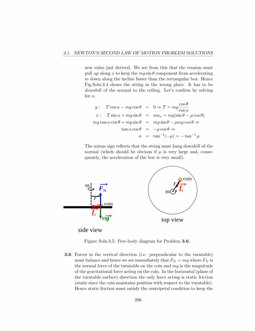
3.1. NEWTON’S SECOND LAW OF MOTION PROBLEM SOLUTIONS
new value just derived. We see from this that the tension mustpull up along x to keep the mg sin θ component from acceleratingm down along the incline faster than the rectangular box. HenceFig.Soln:3.4 shows the string in the wrong place. It has to bedownhill of the normal to the ceiling. Let’s confirm by solvingfor α.
y : T cosα−mg cos θ = 0⇒ T = mgcos θ
cosαx : T sinα+mg sin θ = max = mg(sin θ − µ cos θ)
mg tanα cos θ +mg sin θ = mg sin θ − µmg cos θ ⇒tanα cos θ = −µ cos θ ⇒
α = tan−1(−µ) = − tan−1 µ
The minus sign reflects that the string must hang downhill of thenormal (which should be obvious if µ is very large and, conse-quently, the acceleration of the box is very small).
side view top view
r coin
ω ω
r coin
FN
mg
fs
fs
Figure Soln:3.5: Free-body diagram for Problem 3.6.
3.6. Forces in the vertical direction (i.e. perpendicular to the turntable)must balance and hence we see immediately that FN = mg where FN isthe normal force of the turntable on the coin and mg is the magnitudeof the gravitational force acting on the coin. In the horizontal (plane ofthe turntable surface) direction the only force acting is static friction(static since the coin maintains position with respect to the turntable).Hence static friction must satisfy the centripetal condition to keep the
296
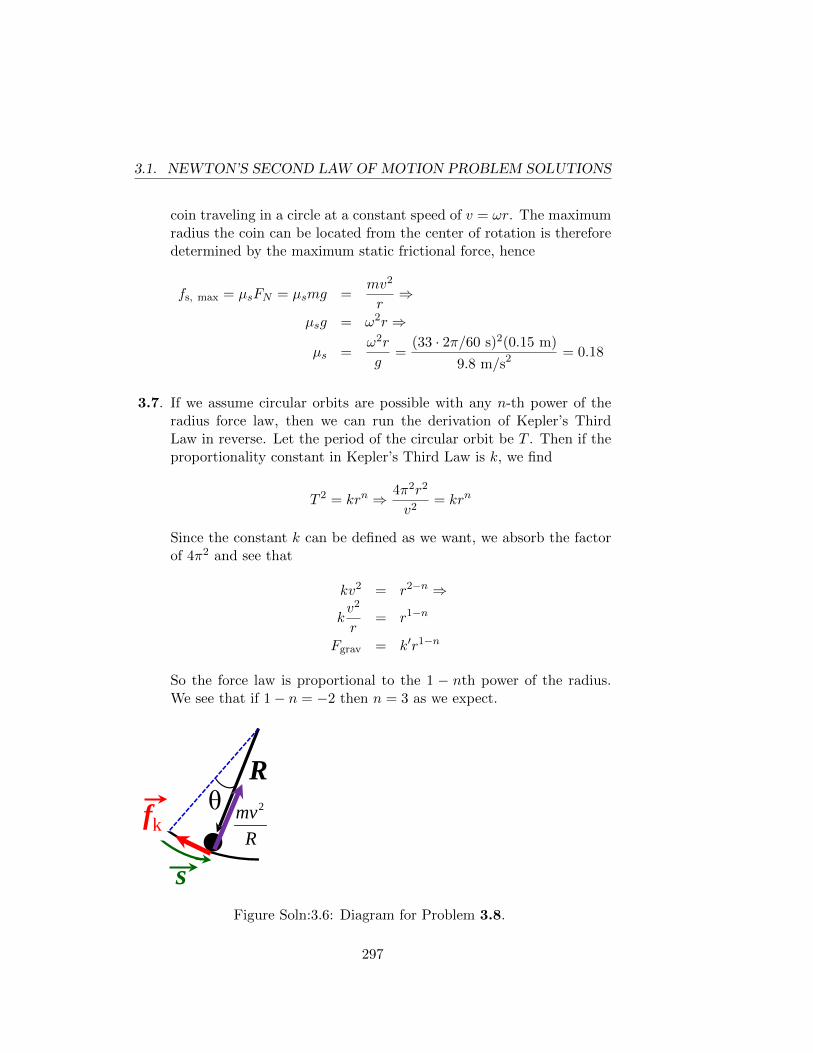
3.1. NEWTON’S SECOND LAW OF MOTION PROBLEM SOLUTIONS
coin traveling in a circle at a constant speed of v = ωr. The maximumradius the coin can be located from the center of rotation is thereforedetermined by the maximum static frictional force, hence
fs, max = µsFN = µsmg =mv2
r⇒
µsg = ω2r ⇒
µs =ω2r
g=
(33 · 2π/60 s)2(0.15 m)
9.8 m/s2 = 0.18
3.7. If we assume circular orbits are possible with any n-th power of theradius force law, then we can run the derivation of Kepler’s ThirdLaw in reverse. Let the period of the circular orbit be T . Then if theproportionality constant in Kepler’s Third Law is k, we find
T 2 = krn ⇒ 4π2r2
v2= krn
Since the constant k can be defined as we want, we absorb the factorof 4π2 and see that
kv2 = r2−n ⇒
kv2
r= r1−n
Fgrav = k′r1−n
So the force law is proportional to the 1 − nth power of the radius.We see that if 1− n = −2 then n = 3 as we expect.
R
s
θ R
mv2fk
Figure Soln:3.6: Diagram for Problem 3.8.
297
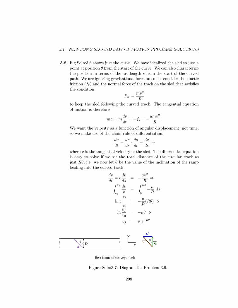
3.1. NEWTON’S SECOND LAW OF MOTION PROBLEM SOLUTIONS
3.8. Fig.Soln:3.6 shows just the curve. We have idealized the sled to just apoint at position θ from the start of the curve. We can also characterizethe position in terms of the arc-length s from the start of the curvedpath. We are ignoring gravitational force but must consider the kineticfriction (fk) and the normal force of the track on the sled that satisfiesthe condition
FN =mv2
Rto keep the sled following the curved track. The tangential equationof motion is therefore
ma = mdv
dt= −fs = −µmv
2
R.
We want the velocity as a function of angular displacement, not time,so we make use of the chain rule of differentiation.
dv
dt=dv
ds· dsdt
=dv
ds· v
where v is the tangential velocity of the sled. The differential equationis easy to solve if we set the total distance of the circular track asjust Rθ, i.e. we now let θ be the value of the inclination of the rampleading into the curved track.
dv
dt= v
dv
ds= −µv
2
R⇒∫ vf
v0
dv
v=
∫ Rθ
0− µRds
ln v
∣∣∣∣vfv0
= − µR
(Rθ)⇒
lnvfv0
= −µθ ⇒
vf = v0e−µθ
D d θ
Rest frame of conveyor belt
θ v0 v
V
x
y
Figure Soln:3.7: Diagram for Problem 3.9.
298
3.1. NEWTON’S SECOND LAW OF MOTION PROBLEM SOLUTIONS
3.9. The hint steers us to consider the inertial frame to be that wherethe conveyor belt is at rest, i.e. a frame moving with respect to thefloor at velocity ~V . In the floor’s frame, the puck would execute acurved path as it slows its velocity relative to the conveyor belt. Thismakes calculating the effect of friction tricky. In the rest frame of theconveyor belt, the puck moves along a straight line since there areno forces acting perpendicular to the path of the puck in this frame(except for gravity which points downward and hence has no directeffect on the puck’s motion relative to the conveyor belt). The puckgoes diagonally backward in this frame and, since the frictional forceis bounded, the velocity of the puck (relative to the floor) is still ~v0
just after the puck is on the belt.
The kinetic friction force is µmg with m being the mass of the puckso the acceleration along the path has magnitude µg. Looking at they component of the puck’s motion, the acceleration due to friction is
ay = −µg cos θ = µgv0√
v20 + V 2
The minimum value of v0 has the puck just reaching the other edge ofthe belt as its y velocity goes to zero, so
v2y = v2
0 + 2ayy
0 = v20 −
2µgv0D√v2
0 + V 2⇒
v40 =
(2µgD)2v20
v20 + V 2
We could also get to this equation by considering motion along thediagonal. In that case we have
0 = v20 + V 2 − 2µg
D
cos θ⇒
=√v2
0 + V 2 − 2µgD
v0⇒
v40 =
(2µgD)2v20
v20 + V 2
299
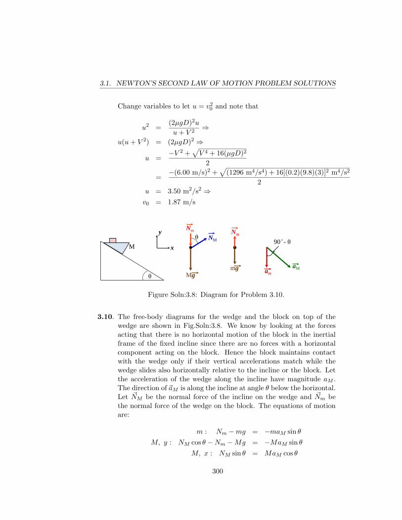
3.1. NEWTON’S SECOND LAW OF MOTION PROBLEM SOLUTIONS
Change variables to let u = v20 and note that
u2 =(2µgD)2u
u+ V 2⇒
u(u+ V 2) = (2µgD)2 ⇒
u =−V 2 +
√V 4 + 16(µgD)2
2
=−(6.00 m/s)2 +
√(1296 m4/s4) + 16[(0.2)(9.8)(3)]2 m4/s2
2u = 3.50 m2/s2 ⇒v0 = 1.87 m/s
θ
M θ
Nm Nm
Mg mg
x
y NM
aM am
90 - θ
Figure Soln:3.8: Diagram for Problem 3.10.
3.10. The free-body diagrams for the wedge and the block on top of thewedge are shown in Fig.Soln:3.8. We know by looking at the forcesacting that there is no horizontal motion of the block in the inertialframe of the fixed incline since there are no forces with a horizontalcomponent acting on the block. Hence the block maintains contactwith the wedge only if their vertical accelerations match while thewedge slides also horizontally relative to the incline or the block. Letthe acceleration of the wedge along the incline have magnitude aM .The direction of ~aM is along the incline at angle θ below the horizontal.Let ~NM be the normal force of the incline on the wedge and ~Nm bethe normal force of the wedge on the block. The equations of motionare:
m : Nm −mg = −maM sin θ
M, y : NM cos θ −Nm −Mg = −MaM sin θ
M, x : NM sin θ = MaM cos θ
300
3.1. NEWTON’S SECOND LAW OF MOTION PROBLEM SOLUTIONS
The simultaneous solution for these three equations in the three un-knowns NM , Nm, and aM is
NM =(m+M)Mg cos θ
M +m sin2 θ
Nm =mMg cos2 θ
M +m sin2 θ
aM =(m+M)g sin θ
M +m sin2 θ
The acceleration ~aM parallel to the incline is the solution requested.
We can use less algebra to get the solution if we note that the accel-eration of the block along the vertical direction must be
ay = aM sin θ
and its acceleration along the direction of the incline is
ay cos(90◦ − θ) = aM sin2 θ.
Then looking only at the components of the force on the wedge andblock which are parallel to the incline, we have
mg sin θ −Nm sin θ = maM sin2 θ
Mg sin θ +Nm sin θ = MaM
Adding the two equations gives the wedge acceleration immediately.
(m+M)g sin θ = aM (M +m sin2 θ)⇒
aM =(m+M)g sin θ
M +m sin2 θ
3.11. For M to be in equilibrium we should have the tension in the stringequal to the weight Mg. The conditions for minimum and maximumradius of the toy car are therefore set when the maximum static fric-tional force points inward and outward, respectively, with respect tothe center of the circular path (see Fig.Soln:3.9). We see this becausethe centripetal condition requires, according to Fig.Soln:3.9,
~T + ~fs = −mv2
ri⇒ − (T ± fs) i = −mv
2
ri
301
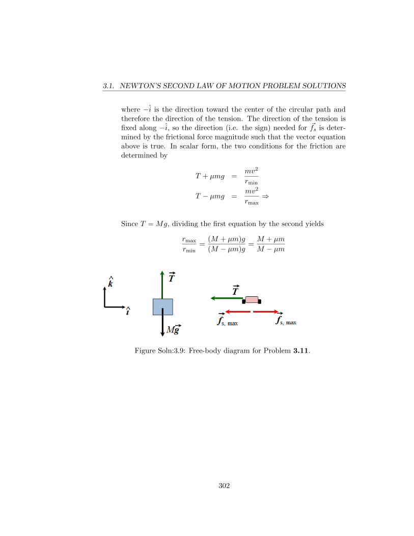
3.1. NEWTON’S SECOND LAW OF MOTION PROBLEM SOLUTIONS
where −i is the direction toward the center of the circular path andtherefore the direction of the tension. The direction of the tension isfixed along −i, so the direction (i.e. the sign) needed for ~fs is deter-mined by the frictional force magnitude such that the vector equationabove is true. In scalar form, the two conditions for the friction aredetermined by
T + µmg =mv2
rmin
T − µmg =mv2
rmax⇒
Since T = Mg, dividing the first equation by the second yields
rmax
rmin=
(M + µm)g
(M − µm)g=M + µm
M − µm
Figure Soln:3.9: Free-body diagram for Problem 3.11.
302
Appendix 4
MOMENTUM
4.1 Momentum Problem Solutions
4.1. Note that the definition of center of mass location with respect to theorigin is
~R =
∑imi~ri∑imi
For each particle n in the system∣∣∣~R− ~rn∣∣∣2 =
(∑imi~riM
− ~rn)·(∑
jmj~rj
M− ~rn
)
=1
M2
[∑i
mi (~ri − ~rn)
]·
∑j
mj (~rj − ~rn)
Now (~ri − ~rn) ·(~rj − ~rn) is unchanged under all possible motions of therigid body of which mi, mj , and mn are part. Therefore the distanceof the CM from all particles (index n) in the body is unchanged underall motions of the body. Hence CM is a point of the body.
4.2. The total force on the floor at any given amount of rope drop y, i.e.whenever the top of the rope has fallen a distance y below its initialrelease point and therefore there is a total length of rope y already onthe floor, is
F (y) =dp
dt+mg
303
4.1. MOMENTUM PROBLEM SOLUTIONS
where dp/dt is the magnitude of the force necessary to bring an in-finitesimal length of rope with mass dm to a halt if it has acquiredspeed v in its fall and hence, by Newton’s Third Law, the rope con-tributes this magnitude of force to the table. m is the mass of ropealready on the table and is therefore equal to λy with λ = M/L. Theinstantaneous velocity for any infinitesimal length of rope dm can becalled v where v2 = 2gy since we consider dm to be in free-fall. There-fore, dp = dm v and dm = λ ·dy with dy being the infinitesimal lengthcorresponding to mass dm. Thus,
F (y) = vdm
dt+ λyg
= v ·(λ dy
dt
)+ λyg
= v2λ+ λyg
F (y) = 2gy · λ+ λyg = 3λgy
To answer part b. we just note that the maximum force occurs wheny is maximum, i.e. y = L so the maximum force is 3Mg and occurswhen the last bit of rope hits the table. This makes sense because thislast dm hits with the maximum speed (since it falls from the greatestheight, L) and the (nearly) maximum weight of rope is already on thetable.
4.3. (a) Linear momentum conservation demands
~p1 = −~p2
where ~p1 and ~p2 are the momenta of fragments 1 and 2, respec-tively. The fragments must fly off in directions that are collinear.So, the horizontal velocities can be determined from the distancestraveled and the times given.
v1x =120 m
10.0 s= 12.0 m/s
v2x =24.0 m
4.00 s= 6.00 m/s
Given that the sum of the x momenta for the fragments must addto zero, we have
p1x = m1v1x = p2x = m2v2x ⇒ (E.1)
m2 = m112.0
6.00= 2m1 (E.2)
304
4.1. MOMENTUM PROBLEM SOLUTIONS
When the skyrocket reaches its highest point its velocity is zeroso the vertical momenta of the fragments must also be equal inmagnitude and opposite signs.
m1v1y = −m2v2y ⇒ v1y = −2v2y
If we use the explosion site as the origin of our coordinate systemthen the vertical drop of the fragments is described by
−h = v1y(10 s)− 9.8 m/s2
2(100 s2)
−h = (10v1y − 490) m
and
−h = v2y(4 s)− 9.8 m/s2
2(16 s2)
= (−2v1y − 78.4) m⇒10v1y − 490 = −2v1y − 78.4⇒
v1y = 34.3 m/s⇒ v2y = −17.2 m/s⇒h = (4 s)(17.15 m/s) + 78.4 m
= 147 m
(b) Given that fragment 1 goes up, we get the maximum height fromthat fragment’s travel. With the ground as the origin, we have
0 = v21y − 2(9.8 m/s2)(ymax − 147 m)⇒
ymax = 147 m +(34.3 m/s)2
19.6 m/s2= 207 m
305
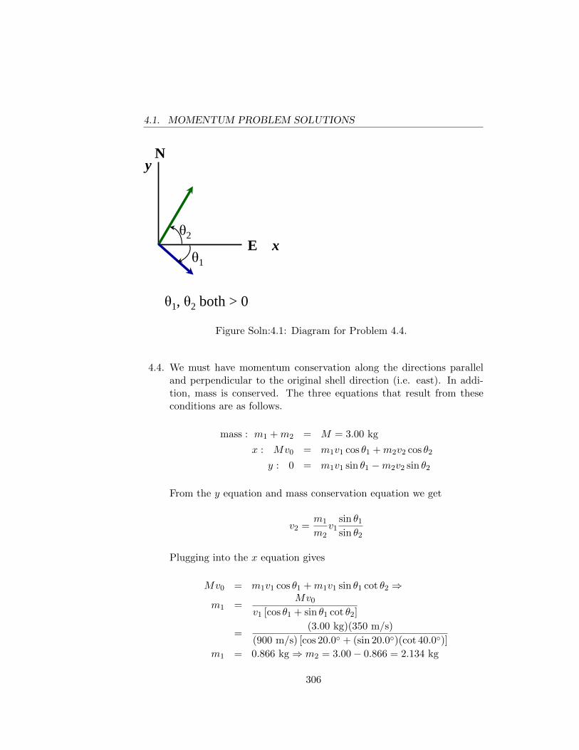
4.1. MOMENTUM PROBLEM SOLUTIONS
N
E x
y
θ1
θ2
θ1, θ2 both > 0
Figure Soln:4.1: Diagram for Problem 4.4.
4.4. We must have momentum conservation along the directions paralleland perpendicular to the original shell direction (i.e. east). In addi-tion, mass is conserved. The three equations that result from theseconditions are as follows.
mass : m1 +m2 = M = 3.00 kg
x : Mv0 = m1v1 cos θ1 +m2v2 cos θ2
y : 0 = m1v1 sin θ1 −m2v2 sin θ2
From the y equation and mass conservation equation we get
v2 =m1
m2v1
sin θ1
sin θ2
Plugging into the x equation gives
Mv0 = m1v1 cos θ1 +m1v1 sin θ1 cot θ2 ⇒
m1 =Mv0
v1 [cos θ1 + sin θ1 cot θ2]
=(3.00 kg)(350 m/s)
(900 m/s) [cos 20.0◦ + (sin 20.0◦)(cot 40.0◦)]
m1 = 0.866 kg⇒ m2 = 3.00− 0.866 = 2.134 kg
306
4.1. MOMENTUM PROBLEM SOLUTIONS
Therefore
v2 =m1
m2v1
sin θ1
sin θ2
=0.866 kg
2.134 kg(900 m/s)
sin 20.0◦
sin 40.0◦
v2 = 194 m/s
Note: Many students miss this problem because they have two equa-tions (x and y momenta) in 3 unknowns and did not realize the con-straint on the sum of the masses of the fragments constitutes the thirdequation!
4.5. The thrust is a force with magnitude equal to the time rate of momen-tum change of the exhaust gas. The time rate of change of the massof the rocket is the time rate of mass of fuel expended as exhaust gas,so∣∣∣∣dMdt
∣∣∣∣ =fuel burned
burn time=
2.300× 10⁶ kg − 1.310× 10⁵ kg
150 s= 1.446×10⁴ kg/s
The thrust magnitude, T , is therefore
T = u
∣∣∣∣dMdt∣∣∣∣⇒
u =T
|dM/dt|
=3.402× 10⁷ N
1.446× 10⁴ kg/s
u = 2.35× 10³ m/s
We should note that the ideal rocket equation (Eqn.( 4.14)) is notso accurate here since we have to consider the effect of gravity. Themodification comes in Eqn.( 4.13) where, instead of having momentumbe conserved, we must look at the change in momentum due to anexternal gravitational force, i.e.
(Mv −Mg dt) i = (M + dM)(v + dv) i− dM(v − u) i⇒Mv −Mg dt = Mv +M dv + v dM + dM dv − v dM + u dM ⇒
M dv = −u dM −Mg dt
307
4.1. MOMENTUM PROBLEM SOLUTIONS
where we drop the product of differentials and we note that dM isnegative. Dividing through by M as in Chapter 4 and eliminating dtby noting that
dt =dM
dM/dt
yields
dv = −u dM
M− g dM
dM/dt
Integrating then gives (remember that dM < 0)∫ v
v0
dv′ = −u∫ M
M0
dM ′
M ′− g
dM/dt
∫ M
M0
dM ′ ⇒
v − v0 = −u lnM
M0− gM −M0
dM/dt.
The ideal rocket equation modified by gravity is
v = v0 − u ln
(M
M0
)− gM −M0
dM/dt
There are two assumptions made here. The first is that 67 kilometersis a small enough altitude relative to the earth’s radius that we cancontinue to use g = 9.80 m/s2 as the gravitational acceleration. Wehave also assumed that at time t = 0
M0dv
dt= −udM
dt−M0g > 0⇒ −udM
dt> M0g
otherwise the rocket does not initially lift off but just sits on the launchpad burning fuel until the total mass is sufficiently small enough forthe thrust to lift the rocket.
The relevant numbers for this problem require us to get the mass atthe end of the first stage firing. These numbers are
M0 = 2.80× 10⁶ kg
M = launch mass−mass of 1st stage
= (2.8× 10⁶ − 2.3× 10⁶) kg
u = exhaust velocity = 2.35× 10³ m/s
t = time for first stage = 150 s
308
4.1. MOMENTUM PROBLEM SOLUTIONS
Therefore the velocity of the rocket at 67 kilometers altitude would be
v = 0−(2.35× 10³ m/s
)ln
(5.00× 10⁵ kg
2.80× 10⁶ kg
)− (9.80 m/s2)(150 s)
= 2.578× 10³ m/s
4.6. We know the velocity of the cannonball, but in a non-inertial frame.As the cannonball accelerates along the barrel of the cannon, the factthat the cannonball is accelerating means that a force is being exertedon it by the cannon and hence the cannon must have a force exertedon it by the cannonball according to Newton’s third law. As the can-nonball exits the cannon, it is moving at angle α with respect to thehorizontal in the inertial frame (fixed with respect to the ground). Thespeed of the flatcar is calculable since the momentum of the systemalong the horizontal (x) is conserved as there are no external forcesacting along x. Call the speed of the flatcar along the x-axis u just asthe cannonball leaves the barrel. The appropriate vector diagram forfinding the velocity of the cannonball is Fig.Soln:4.2 where ~V ′ is thefinal velocity of the cannonball with respect to the ground. Momen-tum conservation along the x-axis yields (assuming to the right is thepositive x direction)
mV ′ cosα = Mu
mV cos θ −mu = Mu⇒
u =mV cos θ
m+M
The angle α is derived from the vector diagram by noting that V ′y = Vy,i.e. the vertical components are equal. The horizontal component of~V ′ we have already calculated above. Thus,
V ′y = V ′ sinα = V sin θ
V ′x = V ′ cosα =Mu
m⇒
V ′yV ′x
= tanα =m
Mu· V sin θ ⇒
=mV sin θ
M· m+M
mV cos θ
tanα =m+M
Mtan θ
309
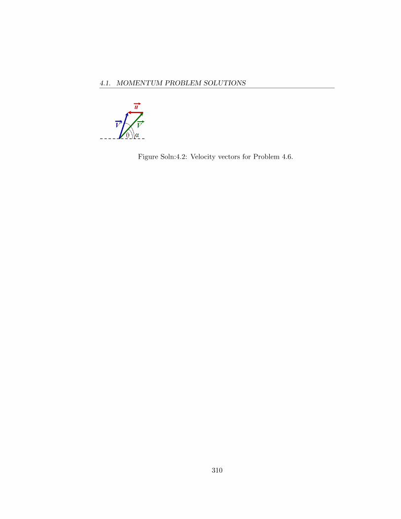
4.1. MOMENTUM PROBLEM SOLUTIONS
Figure Soln:4.2: Velocity vectors for Problem 4.6.
310
Appendix 5
WORK AND ENERGY
5.1 Work and Conservation of Energy ProblemSolutions
5.1. Assume that the racket and ball meet in a one-dimensional elasticcollision as conserving kinetic energy in the collision leaves more energyfor the ball and hence corresponds to the highest velocity it can have.In such a case we can use the velocity exchange formula, i.e. vball −vracket = −(uball − uracket) where u indicates initial velocity and vindicates final velocity just after the collision. Using this, we see thatthe relative velocity of racket and ball becomes
vball − vracket = −(−uball − uracket)
where the −u0 occurs since the ball is moving opposite to the directionof the racket (which we assume is positive x direction). However theracket is held by the player and its velocity does not change (or atleast not by an appreciable amount). So vracket = u1. Therefore
vball − uracket = uball + uracket ⇒ vball, max = uball + 2uracket
Even if you didn’t know the velocity exchange formula, you can visu-alize the collision in an inertial frame moving with the same constantvelocity as the racket. In this frame the racket looks like a stationarywall and the ball approaches the wall with speed uball + uracket andrebounds with equal speed in the opposite direction. Relative to theground, the velocity of the rebounding ball is therefore uball + 2uracket.
311
5.1. WORK AND CONSERVATION OF ENERGY PROBLEMSOLUTIONS
5.2. Let u be the velocity of the block relative to the wedge. We usethis velocity since its direction is always known relative to the wedge.For the system consisting of the block and wedge but not the tableon which the wedge rests, we have (assuming the x-axisis along thehorizontal with +x being to the right)
∑Px = 0 = −MV +m(u cos θ − V )⇒
u cos θ =M +m
mV ⇒
u =M +m
m
V
cos θ⇒
u sin θ =M +m
mV tan θ .
where V is the speed of the wedge. By use of energy conservation andthe substitution of u cos θ from the momentum equation we have
KE0 + U0 = KEfinal + Ufinal
mgh =1
2MV 2 +
1
2m[(u cos θ − V )2 + (u sin θ)2
]⇒
2mgh = MV 2 +m
[(M
mV + V − V
)2
+
(M +m
mV tan θ
)2]
= V 2
[M +
M2
m+
(M +m)2
mtan2 θ
]⇒
2m2gh = V 2[M(M +m) + (M +m)2 tan2 θ
]⇒
2m2gh
M +m= V 2
[M + (M +m) tan2 θ
]= V 2
[M cos2 θ +M sin2 θ +m sin2 θ
cos2 θ
]⇒
V =
√2m2gh cos2 θ
(M +m)(M +m sin2 θ)
5.3. (a) The jumper’s maximum velocity occurs at the point where thebungee cord exerts a force which just counteracts gravity (atwhich point the jumper’s acceleration is zero). After this pointthe acceleration is upward and the jumper decelerates until com-
312
5.1. WORK AND CONSERVATION OF ENERGY PROBLEMSOLUTIONS
ing to rest momentarily and then moves upward.
Fjumper = mg − kx = 0⇒
x =mg
k
=(80.0 kg)(9.80 m/s2)
200. N/m
x = 3.92 m
So the maximum velocity occurs at 53.9 meters below the bridge.
(b) The maximum velocity occurs when the bungee cord is stretchedby 3.92 meters, so, setting the coordinate system origin at 50.0meters below the bridge,
KE0 + PE0 = KEf + PEf
0 +mg(50.0) =1
2mv2
max +mg(−3.92 m) +1
2k(3.92 m)2 ⇒
vmax =
√2(9.80 m/s2)(53.92 m)− (200 N/m)(3.92 m)2
80.0 kg
= 32.4 m/s
(c) The maximum acceleration occurs for the maximum net forceacting on the jumper. Until the 50.0 meters is reached onlygravity acts and the jumper’s acceleration is 9.80 m/s2. Oncethe bungee cord is stretched by more than 3.92 meters, the netforce is upward. The question is then whether the net force ofkx − mg > |mg| for any point before the velocity goes to zerosince at the stop point the cord is at its maximum length for thisjumper and exerting the maximum upward force. Hence we wantto find the maximum stretch of the rope, xmax. Let mg/k = δ asa shorthand.
mg(50.0 + x) =1
2kx2
max ⇒
100δ + 2δxmax = x2max ⇒
x2max − 2δxmax − 100δ = 0⇒
xmax = δ
[1 +
√1 +
100
δ
]
313
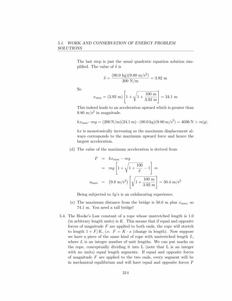
5.1. WORK AND CONSERVATION OF ENERGY PROBLEMSOLUTIONS
The last step is just the usual quadratic equation solution sim-plified. The value of δ is
δ =(80.0 kg)(9.80 m/s2)
200 N/m= 3.92 m
So
xmax = (3.92 m)
[1 +
√1 +
100 m
3.92 m
]= 24.1 m
This indeed leads to an acceleration upward which is greater than9.80 m/s2 in magnitude.
kxmax−mg = (200 N/m)(24.1 m)−(80.0 kg)(9.80 m/s2) = 4036 N > m|g|.
kx is monotonically increasing so the maximum displacement al-ways corresponds to the maximum upward force and hence thelargest acceleration.
(d) The value of the maximum acceleration is derived from
F = kxmax −mg
= mg
[1 +
√1 +
100
δ− 1
]⇒
amax =(9.8 m/s2
) [√1 +
100 m
3.92 m
]= 50.4 m/s2
Being subjected to 5g’s is an exhilarating experience.
(e) The maximum distance from the bridge is 50.0 m plus xmax, so74.1 m. You need a tall bridge!
5.4. The Hooke’s Law constant of a rope whose unstretched length is 1.0(in arbitrary length units) is K. This means that if equal and oppositeforces of magnitude F are applied to both ends, the rope will stretchto length 1 + F/K, i.e. F = K · x (change in length). Now supposewe have a piece of the same kind of rope with unstretched length L,where L is an integer number of unit lengths. We can put marks onthe rope, conceptually dividing it into L (note that L is an integerwith no units) equal length segments. If equal and opposite forcesof magnitude F are applied to the two ends, every segment will bein mechanical equilibrium and will have equal and opposite forces F
314
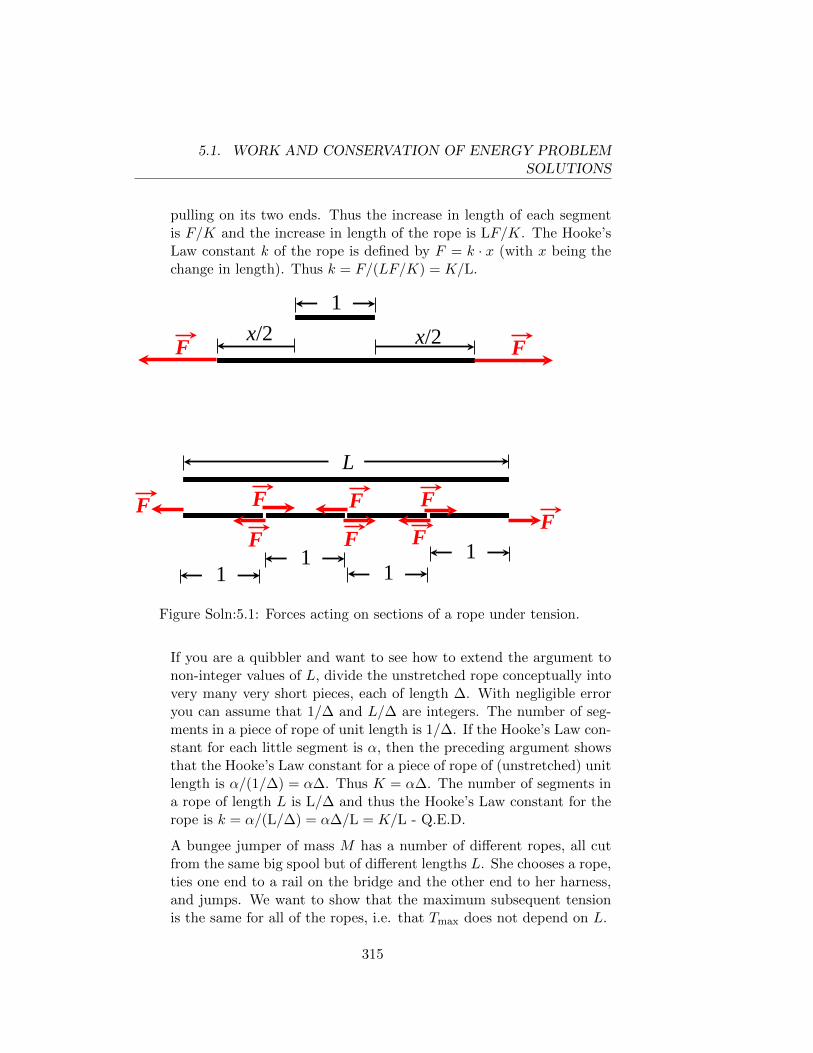
5.1. WORK AND CONSERVATION OF ENERGY PROBLEMSOLUTIONS
pulling on its two ends. Thus the increase in length of each segmentis F/K and the increase in length of the rope is LF/K. The Hooke’sLaw constant k of the rope is defined by F = k · x (with x being thechange in length). Thus k = F/(LF/K) = K/L.
x/2 x/2 1
F F
L
F
F
F F
F F
F F
1 1
1 1
Figure Soln:5.1: Forces acting on sections of a rope under tension.
If you are a quibbler and want to see how to extend the argument tonon-integer values of L, divide the unstretched rope conceptually intovery many very short pieces, each of length ∆. With negligible erroryou can assume that 1/∆ and L/∆ are integers. The number of seg-ments in a piece of rope of unit length is 1/∆. If the Hooke’s Law con-stant for each little segment is α, then the preceding argument showsthat the Hooke’s Law constant for a piece of rope of (unstretched) unitlength is α/(1/∆) = α∆. Thus K = α∆. The number of segments ina rope of length L is L/∆ and thus the Hooke’s Law constant for therope is k = α/(L/∆) = α∆/L = K/L - Q.E.D.
A bungee jumper of mass M has a number of different ropes, all cutfrom the same big spool but of different lengths L. She chooses a rope,ties one end to a rail on the bridge and the other end to her harness,and jumps. We want to show that the maximum subsequent tensionis the same for all of the ropes, i.e. that Tmax does not depend on L.
315
5.1. WORK AND CONSERVATION OF ENERGY PROBLEMSOLUTIONS
Clearly the maximum tension occurs when the rope is maximallystretched, i.e. when the jumper is at her low point and has zero ve-locity. Let the length of the rope at this point be L + x. We takethe jumper’s gravitational potential energy as zero at the bridge andthus it equals −Mg(L+ x) at the low point. Because the rope’s massis much less than the jumper’s, we neglect its gravitational P.E. TheP.E. of the unstretched rope is zero and the P.E. of the stretched ropeis 1
2kx2. The jumper’s K.E. is zero on the bridge and zero at the low
point.
Thus 0 = −Mg(L+x)+ 12kx2. We could solve this quadratic equation
for its positive root and then calculate the maximum tension Tmax =kx = (K/L)x. If the statement of the problem is correct, then Tmax
does not depend on L, i.e. x/L does not depend on L. We can seethis even without solving the quadratic equation. Let y = x/L. Thenx = yL and our equation is
0 = −Mg(L+ yL) + 12(K/L)(yL)2 ⇒
= −Mg(1 + y) + 12Ky2
Note that L has disappeared, so its clear that y and Tmax do notdepend on L. This fact is known to many jumpers and rock climbers.
5.5. We seek to prove that if linear momentum is conserved in one frame,i.e. for a system of n particles
n∑j=1
mj~vji =
n∑j=1
mj~vjf
where the i and f subscripts refer to the velocities before and afterthe collision, then it is true in all other inertial frames. We can writedown the initial and final momenta in any other inertial frame movingwith velocity ~V with respect to the first inertial frame as follows:
n∑j=1
mj~vji − ~V
n∑j=1
mj =
n∑j=1
mj~vjf − ~V
n∑j=1
mj
n∑j=1
mj
(~vji − ~V
)=
n∑j=1
mj
(~vjf − ~V
)n∑j=1
mj~v′ji =
n∑j=1
mj~v′jf
316
5.1. WORK AND CONSERVATION OF ENERGY PROBLEMSOLUTIONS
Hence momentum is also conserved in the new inertial frame. Wenow turn to the argument for kinetic energy associated with motion.Kinetic energy conservation is
n∑j=1
1
2mjv
2ji =
n∑j=1
1
2mjv
2jf
For a different inertial frame A′, as stated above,
n∑j=1
1
2mjv
′ 2ji =
n∑j=1
1
2mj
(~vji − ~V
)2
=n∑j=1
1
2mj
[v2ji − 2~V · ~vji + V 2
]⇒
=
n∑j=1
1
2mj
[v2jf − 2V · ~vji + V 2
]where the last line is from our previous expression for kinetic energyconservation in the original inertial frame. Momentum conservationin the original inertial frame means
n∑j=1
mj~vji =n∑j=1
mj~vjf ⇒
~V ·n∑j=1
mj~vji = ~V ·n∑j=1
mj~vjf ⇒
2~V ·n∑j=1
1
2mj~vji = 2~V ·
n∑j=1
1
2mj~vjf
Therefore, we can rewrite our previous initial kinetic energy for thenew inertial frame as
n∑j=1
1
2mjv
′ 2ji =
n∑j=1
1
2mj
[v2jf − 2~V · ~vjf + V 2
]=
n∑j=1
1
2mj
(~vjf − ~V
)2
n∑j=1
1
2mjv
′ 2ji =
n∑j=1
1
2mjv
′ 2jf
so kinetic energy is conserved in this frame.
317
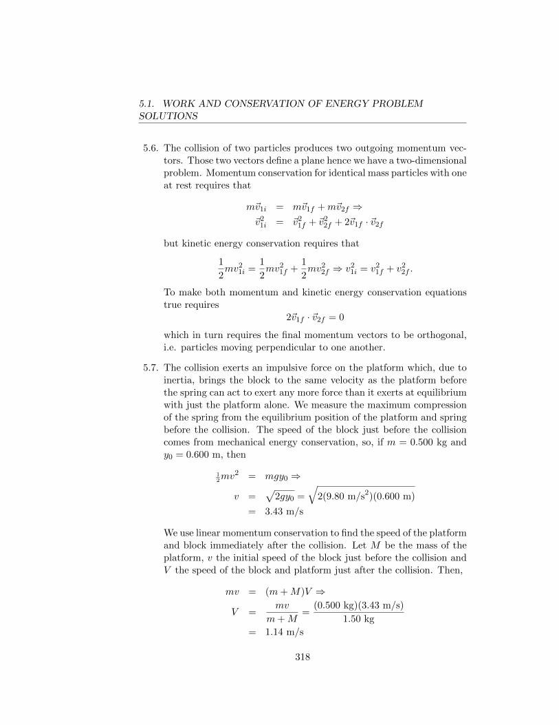
5.1. WORK AND CONSERVATION OF ENERGY PROBLEMSOLUTIONS
5.6. The collision of two particles produces two outgoing momentum vec-tors. Those two vectors define a plane hence we have a two-dimensionalproblem. Momentum conservation for identical mass particles with oneat rest requires that
m~v1i = m~v1f +m~v2f ⇒~v2
1i = ~v21f + ~v2
2f + 2~v1f · ~v2f
but kinetic energy conservation requires that
1
2mv2
1i =1
2mv2
1f +1
2mv2
2f ⇒ v21i = v2
1f + v22f .
To make both momentum and kinetic energy conservation equationstrue requires
2~v1f · ~v2f = 0
which in turn requires the final momentum vectors to be orthogonal,i.e. particles moving perpendicular to one another.
5.7. The collision exerts an impulsive force on the platform which, due toinertia, brings the block to the same velocity as the platform beforethe spring can act to exert any more force than it exerts at equilibriumwith just the platform alone. We measure the maximum compressionof the spring from the equilibrium position of the platform and springbefore the collision. The speed of the block just before the collisioncomes from mechanical energy conservation, so, if m = 0.500 kg andy0 = 0.600 m, then
12mv2 = mgy0 ⇒
v =√
2gy0 =
√2(9.80 m/s2)(0.600 m)
= 3.43 m/s
We use linear momentum conservation to find the speed of the platformand block immediately after the collision. Let M be the mass of theplatform, v the initial speed of the block just before the collision andV the speed of the block and platform just after the collision. Then,
mv = (m+M)V ⇒
V =mv
m+M=
(0.500 kg)(3.43 m/s)
1.50 kg
= 1.14 m/s
318
5.1. WORK AND CONSERVATION OF ENERGY PROBLEMSOLUTIONS
After the collision we can use energy conservation. Let y be the dis-tance the spring compresses from the equilibrium position (which is tosay the equilibrium position at which the platform on top of the springis at rest before the collision with the block). The spring is alreadycompressed by a distance Mg/k before the block hits the platform, so
Kf + Uf = K0 + U0
12k
(Mg
k+ y
)2
= 12(m+M)V 2 + (m+M)gy +
1
2
(Mg
k
)2
⇒
0 = ky2 − 2gmy − (m+M)V 2 ⇒
y =mg +
√m2g2 + kV 2(m+M)
k
=(4.90 N) +
√(4.90 N)2 + (120 N/m)(1.14 m/s)2(1.50 kg)
120 N/m
y = 0.175 m = 17.5 cm
5.8. (a) The qualitative figure is below where we represent x as the dis-tance from one of the planets along the line between the planets.We are free to place the origin of the coordinate system anywherewe like. An easy choice is on the line between the planets. Forthe figure below it is obvious that
|~R1 − ~r| = D − x and |~R2 − ~r| = x
where x is a positive distance. The potential energy function is
u(x) = −GM[
1
x+
1
D − x
]= −GM
[D
x(D − x)
]u(x) = − GM
D(x/D)(1− x/D)
We plot u(x) in arbitrary units of energy.
(b) This problem is somewhat unphysical as the stations cannot sta-bly be at rest with respect to the planets at their positions. Nev-ertheless we take the positions and note that the initial totalmechanical energy of the projectile must exceed the maximum
319
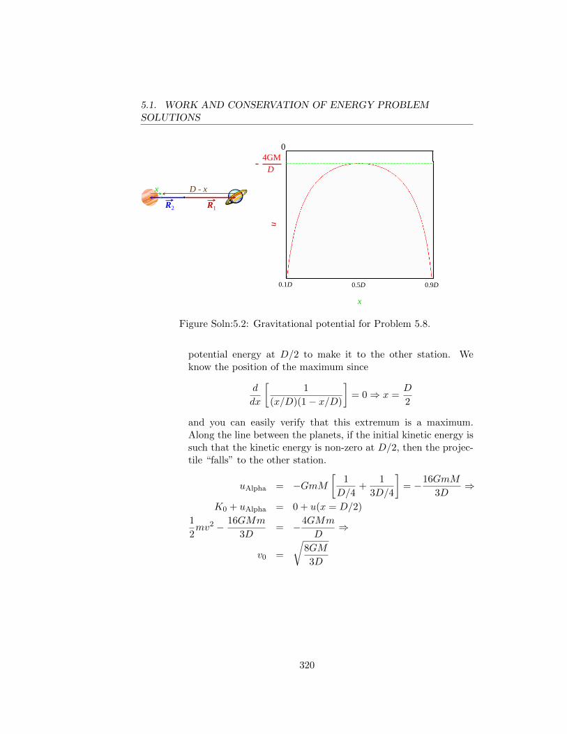
5.1. WORK AND CONSERVATION OF ENERGY PROBLEMSOLUTIONS
R1R2
x D - x
x
0.1D 0.5D 0.9D
u
04GM- D
Figure Soln:5.2: Gravitational potential for Problem 5.8.
potential energy at D/2 to make it to the other station. Weknow the position of the maximum since
d
dx
[1
(x/D)(1− x/D)
]= 0⇒ x =
D
2
and you can easily verify that this extremum is a maximum.Along the line between the planets, if the initial kinetic energy issuch that the kinetic energy is non-zero at D/2, then the projec-tile “falls” to the other station.
uAlpha = −GmM[
1
D/4+
1
3D/4
]= −16GmM
3D⇒
K0 + uAlpha = 0 + u(x = D/2)
1
2mv2 − 16GMm
3D= −4GMm
D⇒
v0 =
√8GM
3D
320
Appendix 6
Simple Harmonic Motion
6.1 Simple Harmonic Motion Problem Solutions
6.1. We showed that the equation of motion is the same as that for a framewhere the gravitational acceleration is modified to ~g ′ where ~g ′ = ~g−~a.The period of the pendulum must therefore be
period = 2π
√`
g′= 2π
√`√
g2 + a2
6.2. The motion of the particle is identical to that of the bob of a simplependulum. The tension in this case is replaced by the normal forceof the bowl surface on the particle. We could use the forces actingon the particle to derive the equation of motion. Let’s instead takethe approach of section 6.4 and look at the mechanical energy. FromFig.Soln:6.1 we see that the height of the particle above the lowestpoint of the spherical surface is
y = R−R cos θ = R(1− cos θ)
There is no friction so all the forces are conservative and we can write
KE + PE = E⇒ 1
2mv2 +mgy = constant
where m is the mass of the particle. We note that the angular speedof the particle at any instant is dθ/dt = v/R. We take the derivative
321
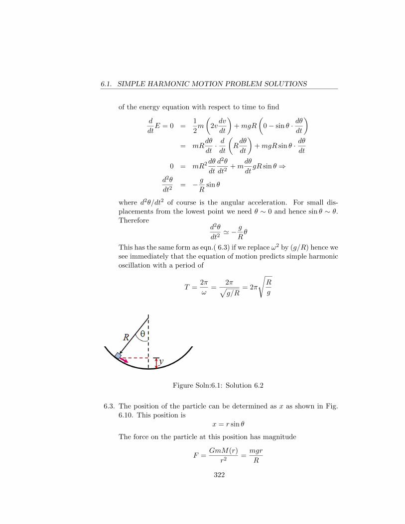
6.1. SIMPLE HARMONIC MOTION PROBLEM SOLUTIONS
of the energy equation with respect to time to find
d
dtE = 0 =
1
2m
(2vdv
dt
)+mgR
(0− sin θ · dθ
dt
)= mR
dθ
dt· ddt
(Rdθ
dt
)+mgR sin θ · dθ
dt
0 = mR2dθ
dt
d2θ
dt2+m
dθ
dtgR sin θ ⇒
d2θ
dt2= − g
Rsin θ
where d2θ/dt2 of course is the angular acceleration. For small dis-placements from the lowest point we need θ ∼ 0 and hence sin θ ∼ θ.Therefore
d2θ
dt2' − g
Rθ
This has the same form as eqn.( 6.3) if we replace ω2 by (g/R) hence wesee immediately that the equation of motion predicts simple harmonicoscillation with a period of
T =2π
ω=
2π√g/R
= 2π
√R
g
Figure Soln:6.1: Solution 6.2
6.3. The position of the particle can be determined as x as shown in Fig.6.10. This position is
x = r sin θ
The force on the particle at this position has magnitude
F =GmM(r)
r2=mgr
R
322
6.1. SIMPLE HARMONIC MOTION PROBLEM SOLUTIONS
where M(r) = Mr3/R3 since the mass density is uniform (and henceequals M/[(4/3)πR3]) and g = GM/R2. The vector component of~F directed perpendicular to the tunnel is offset by the normal forcesholding the particle in the tunnel. The component parallel to thetunnel surface is
Fx = −mgrR· sin θ
where the minus sign indicates that the direction of the force alwayspoints towards the center of the tunnel. At this point θ = 0 and theparallel-directed force is zero hence this point represents an equilibriumposition. Hence the equation describing the particle’s motion is
max = Fx = −mgrR
sin θ = −mgxR⇒
ax =d2x
dt2= − g
Rx
This has the same form as eqn.( 6.3) so we determine this motion to besimple harmonic oscillation along the tunnel with angular frequency
ω =
√g
R.
The time to cross from one end of the tunnel to the other is half aperiod of oscillation
12T = 1
2· 2π ·
√R
g
= (3.14159)
√6.37× 10⁶ m
9.81 m/s2
t = 2530 s = 42.2 minutes
Note that the result is independent of the mass of the particle or lengthof the tunnel! Another interesting note is that the period is equal tothat of a satellite in a circular orbit skimming the rooftops on earth.
6.4. For the top block the normal force due to the bottom block is mg.The maximum horizontal force that can be exerted on the top blockis given by the maximum static frictional force of µmg. Therefore themaximum acceleration possible for the top block before slipping occursis µg. To get the maximum acceleration for the amplitude given we
323
6.1. SIMPLE HARMONIC MOTION PROBLEM SOLUTIONS
refer to eqn.( 6.13). In this case we are free to set the reference pointx0 = 0. The angular frequency is given by
ω2 =k
m+M
From the equation of motion, eqn.( 6.13) we see that the maximum ac-celeration magnitude occurs at the amplitude positions (the maximummagnitude for x), so
amax = −ω2 · xmax = −ω2 ·A
µming =kA
m+M⇒
µmin = 0.136
Of course it is simpler to just note that
amax =Fmax
M +m=
kA
M +m= µming
324
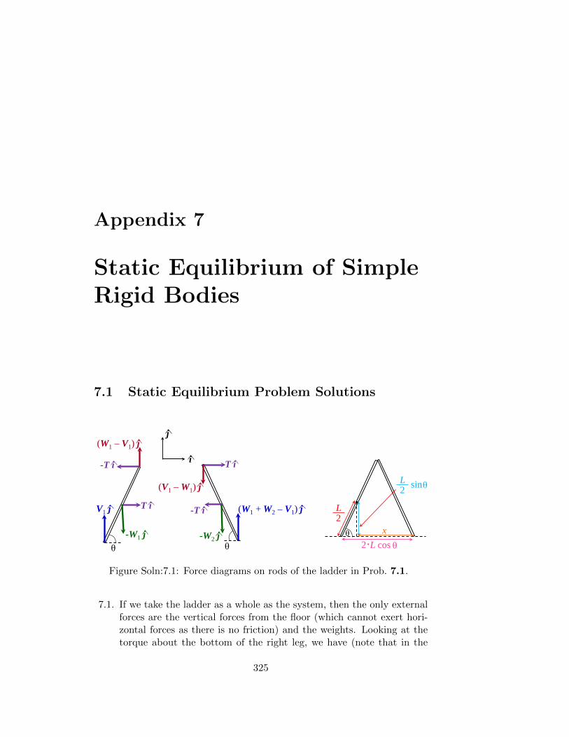
Appendix 7
Static Equilibrium of SimpleRigid Bodies
7.1 Static Equilibrium Problem Solutions
-W1 j
V1 j
θ θ
j
i
T i -T i
-W2 j
(W1 + W2 – V1) j
-T i T i
(W1 – V1) j
(V1 – W1) j
L2θ
L2 sinθ
.2 L cos θx
Figure Soln:7.1: Force diagrams on rods of the ladder in Prob. 7.1.
7.1. If we take the ladder as a whole as the system, then the only externalforces are the vertical forces from the floor (which cannot exert hori-zontal forces as there is no friction) and the weights. Looking at thetorque about the bottom of the right leg, we have (note that in the
325
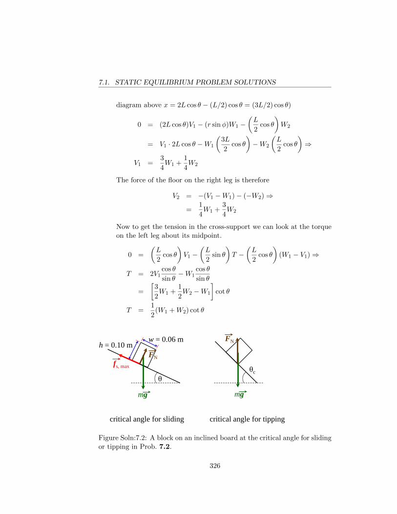
7.1. STATIC EQUILIBRIUM PROBLEM SOLUTIONS
diagram above x = 2L cos θ − (L/2) cos θ = (3L/2) cos θ)
0 = (2L cos θ)V1 − (r sinφ)W1 −(L
2cos θ
)W2
= V1 · 2L cos θ −W1
(3L
2cos θ
)−W2
(L
2cos θ
)⇒
V1 =3
4W1 +
1
4W2
The force of the floor on the right leg is therefore
V2 = −(V1 −W1)− (−W2)⇒
=1
4W1 +
3
4W2
Now to get the tension in the cross-support we can look at the torqueon the left leg about its midpoint.
0 =
(L
2cos θ
)V1 −
(L
2sin θ
)T −
(L
2cos θ
)(W1 − V1)⇒
T = 2V1cos θ
sin θ−W1
cos θ
sin θ
=
[3
2W1 +
1
2W2 −W1
]cot θ
T =1
2(W1 +W2) cot θ
θ
w = 0.06 m h = 0.10 m
mg
fs, max FN
mg
FN
critical angle for tipping
θc
critical angle for sliding
Figure Soln:7.2: A block on an inclined board at the critical angle for slidingor tipping in Prob. 7.2.
326
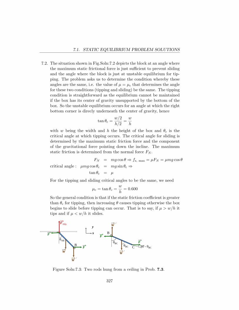
7.1. STATIC EQUILIBRIUM PROBLEM SOLUTIONS
7.2. The situation shown in Fig.Soln:7.2 depicts the block at an angle wherethe maximum static frictional force is just sufficient to prevent slidingand the angle where the block is just at unstable equilibrium for tip-ping. The problem asks us to determine the condition whereby theseangles are the same, i.e. the value of µ = µc that determines the anglefor these two conditions (tipping and sliding) be the same. The tippingcondition is straightforward as the equilibrium cannot be maintainedif the box has its center of gravity unsupported by the bottom of thebox. So the unstable equilibrium occurs for an angle at which the rightbottom corner is direcly underneath the center of gravity, hence
tan θc =w/2
h/2=w
h
with w being the width and h the height of the box and θc is thecritical angle at which tipping occurs. The critical angle for sliding isdetermined by the maximum static friction force and the componentof the gravitational force pointing down the incline. The maximumstatic friction is determined from the normal force FN .
FN = mg cos θ ⇒ fs, max = µFN = µmg cos θ
critical angle : µmg cos θc = mg sin θc ⇒tan θc = µ
For the tipping and sliding critical angles to be the same, we need
µc = tan θc =w
h= 0.600
So the general condition is that if the static friction coefficient is greaterthan θc for tipping, then increasing θ causes tipping otherwise the boxbegins to slide before tipping can occur. That is to say, if µ > w/h ittips and if µ < w/h it slides.
F
W W
FABy
θAB
θBC 90 - θBC
x
y
B
B
C θBC
F
F
F
W
W
Figure Soln:7.3: Two rods hung from a ceiling in Prob. 7.3.
327
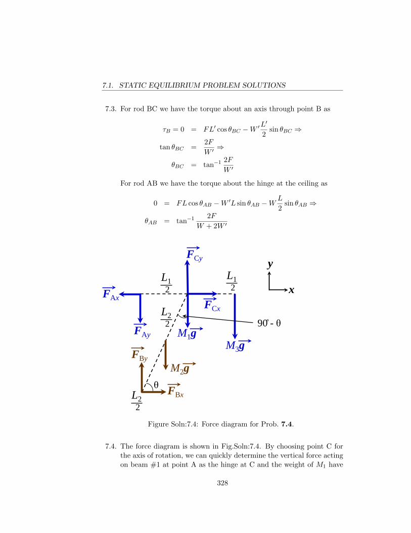
7.1. STATIC EQUILIBRIUM PROBLEM SOLUTIONS
7.3. For rod BC we have the torque about an axis through point B as
τB = 0 = FL′ cos θBC −W ′L′
2sin θBC ⇒
tan θBC =2F
W ′⇒
θBC = tan−1 2F
W ′
For rod AB we have the torque about the hinge at the ceiling as
0 = FL cos θAB −W ′L sin θAB −WL
2sin θAB ⇒
θAB = tan−1 2F
W + 2W ′
M1g M3g
L1 2
L1 2
FCy
FCx x
y
FAx
FAy
FBy
FBx
M2g
L2 2
L2 2
θ
90 - θ
Figure Soln:7.4: Force diagram for Prob. 7.4.
7.4. The force diagram is shown in Fig.Soln:7.4. By choosing point C forthe axis of rotation, we can quickly determine the vertical force actingon beam #1 at point A as the hinge at C and the weight of M1 have
328
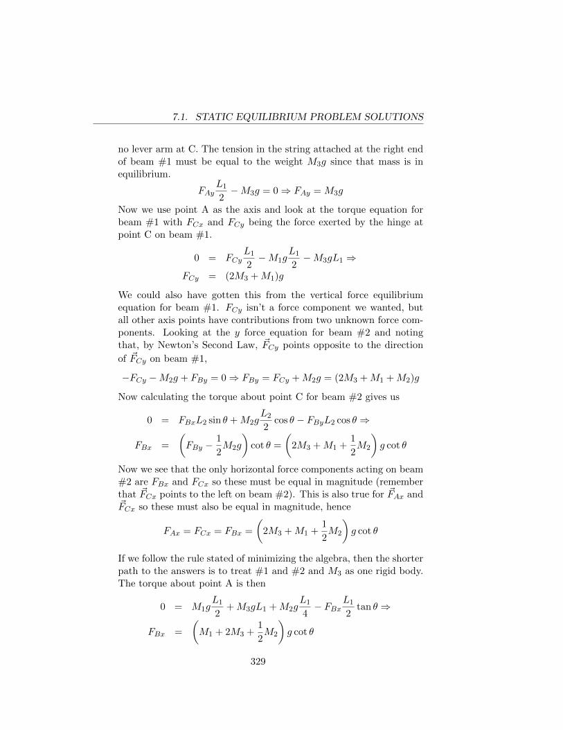
7.1. STATIC EQUILIBRIUM PROBLEM SOLUTIONS
no lever arm at C. The tension in the string attached at the right endof beam #1 must be equal to the weight M3g since that mass is inequilibrium.
FAyL1
2−M3g = 0⇒ FAy = M3g
Now we use point A as the axis and look at the torque equation forbeam #1 with FCx and FCy being the force exerted by the hinge atpoint C on beam #1.
0 = FCyL1
2−M1g
L1
2−M3gL1 ⇒
FCy = (2M3 +M1)g
We could also have gotten this from the vertical force equilibriumequation for beam #1. FCy isn’t a force component we wanted, butall other axis points have contributions from two unknown force com-ponents. Looking at the y force equation for beam #2 and notingthat, by Newton’s Second Law, ~FCy points opposite to the direction
of ~FCy on beam #1,
−FCy −M2g + FBy = 0⇒ FBy = FCy +M2g = (2M3 +M1 +M2)g
Now calculating the torque about point C for beam #2 gives us
0 = FBxL2 sin θ +M2gL2
2cos θ − FByL2 cos θ ⇒
FBx =
(FBy −
1
2M2g
)cot θ =
(2M3 +M1 +
1
2M2
)g cot θ
Now we see that the only horizontal force components acting on beam#2 are FBx and FCx so these must be equal in magnitude (rememberthat ~FCx points to the left on beam #2). This is also true for ~FAx and~FCx so these must also be equal in magnitude, hence
FAx = FCx = FBx =
(2M3 +M1 +
1
2M2
)g cot θ
If we follow the rule stated of minimizing the algebra, then the shorterpath to the answers is to treat #1 and #2 and M3 as one rigid body.The torque about point A is then
0 = M1gL1
2+M3gL1 +M2g
L1
4− FBx
L1
2tan θ ⇒
FBx =
(M1 + 2M3 +
1
2M2
)g cot θ
329
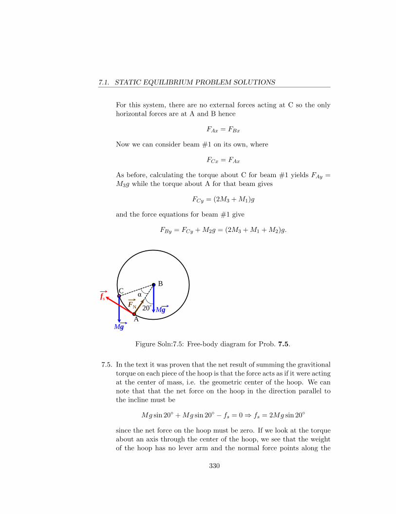
7.1. STATIC EQUILIBRIUM PROBLEM SOLUTIONS
For this system, there are no external forces acting at C so the onlyhorizontal forces are at A and B hence
FAx = FBx
Now we can consider beam #1 on its own, where
FCx = FAx
As before, calculating the torque about C for beam #1 yields FAy =M3g while the torque about A for that beam gives
FCy = (2M3 +M1)g
and the force equations for beam #1 give
FBy = FCy +M2g = (2M3 +M1 +M2)g.
20° A
B C
Mg
Mg
fs α FN
Figure Soln:7.5: Free-body diagram for Prob. 7.5.
7.5. In the text it was proven that the net result of summing the gravitionaltorque on each piece of the hoop is that the force acts as if it were actingat the center of mass, i.e. the geometric center of the hoop. We cannote that that the net force on the hoop in the direction parallel tothe incline must be
Mg sin 20◦ +Mg sin 20◦ − fs = 0⇒ fs = 2Mg sin 20◦
since the net force on the hoop must be zero. If we look at the torqueabout an axis through the center of the hoop, we see that the weightof the hoop has no lever arm and the normal force points along the
330
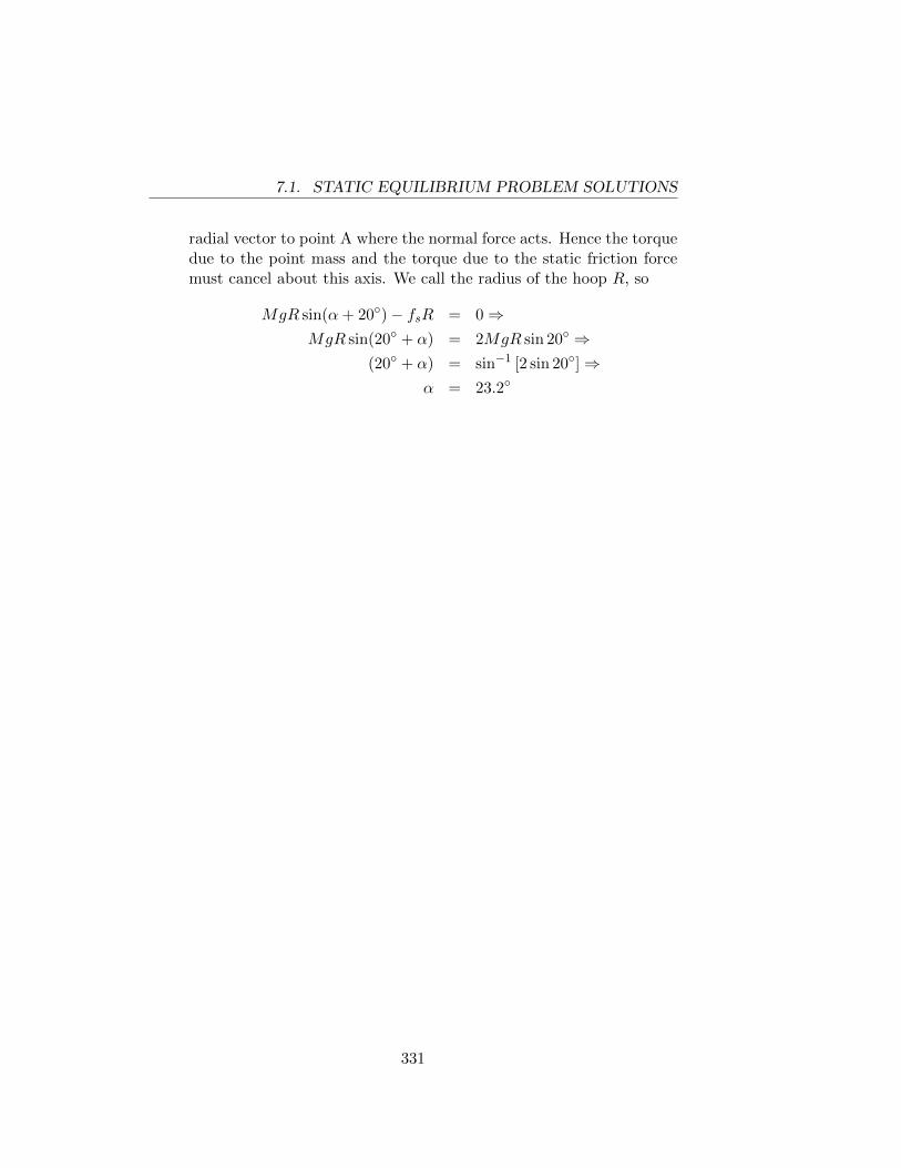
7.1. STATIC EQUILIBRIUM PROBLEM SOLUTIONS
radial vector to point A where the normal force acts. Hence the torquedue to the point mass and the torque due to the static friction forcemust cancel about this axis. We call the radius of the hoop R, so
MgR sin(α+ 20◦)− fsR = 0⇒MgR sin(20◦ + α) = 2MgR sin 20◦ ⇒
(20◦ + α) = sin−1 [2 sin 20◦]⇒α = 23.2◦
331
7.1. STATIC EQUILIBRIUM PROBLEM SOLUTIONS
332
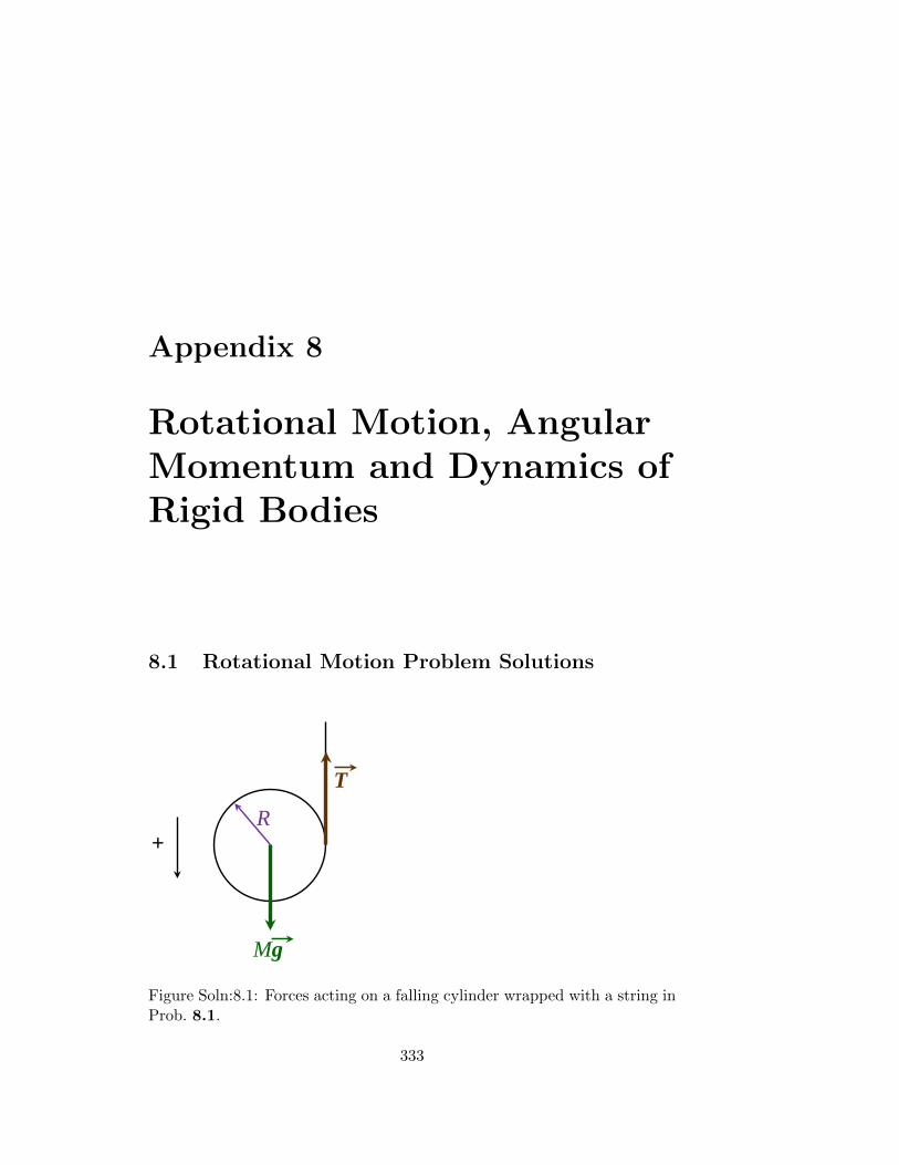
Appendix 8
Rotational Motion, AngularMomentum and Dynamics ofRigid Bodies
8.1 Rotational Motion Problem Solutions
R
Mg
T
+
Figure Soln:8.1: Forces acting on a falling cylinder wrapped with a string inProb. 8.1.
333
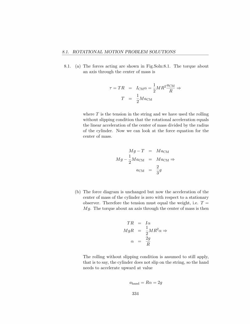
8.1. ROTATIONAL MOTION PROBLEM SOLUTIONS
8.1. (a) The forces acting are shown in Fig.Soln:8.1. The torque aboutan axis through the center of mass is
τ = TR = ICMα =1
2MR2aCM
R⇒
T =1
2MaCM
where T is the tension in the string and we have used the rollingwithout slipping condition that the rotational acceleration equalsthe linear acceleration of the center of mass divided by the radiusof the cylinder. Now we can look at the force equation for thecenter of mass.
Mg − T = MaCM
Mg − 1
2MaCM = MaCM ⇒
aCM =2
3g
(b) The force diagram is unchanged but now the acceleration of thecenter of mass of the cylinder is zero with respect to a stationaryobserver. Therefore the tension must equal the weight, i.e. T =Mg. The torque about an axis through the center of mass is then
TR = Iα
MgR =1
2MR2α⇒
α =2g
R
The rolling without slipping condition is assumed to still apply,that is to say, the cylinder does not slip on the string, so the handneeds to accelerate upward at value
ahand = Rα = 2g
334
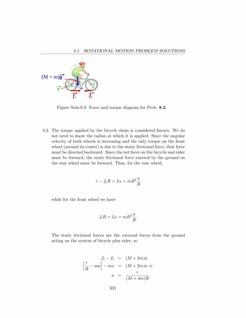
8.1. ROTATIONAL MOTION PROBLEM SOLUTIONS
fr ff
(M + m)g
τ
Figure Soln:8.2: Force and torque diagram for Prob. 8.2.
8.2. The torque applied by the bicycle chain is considered known. We donot need to know the radius at which it is applied. Since the angularvelocity of both wheels is increasing and the only torque on the frontwheel (around its center) is due to the static frictional force, that forcemust be directed backward. Since the net force on the bicycle and ridermust be forward, the static frictional force exerted by the ground onthe rear wheel must be forward. Thus, for the rear wheel,
τ − frR = Iα = mR2 a
R
while for the front wheel we have
ffR = Iα = mR2 a
R.
The static frictional forces are the external forces from the groundacting on the system of bicycle plus rider, so
fr − ff = (M + 2m)a[ τR−ma
]−ma = (M + 2m)a⇒
a =τ
(M + 4m)R
335
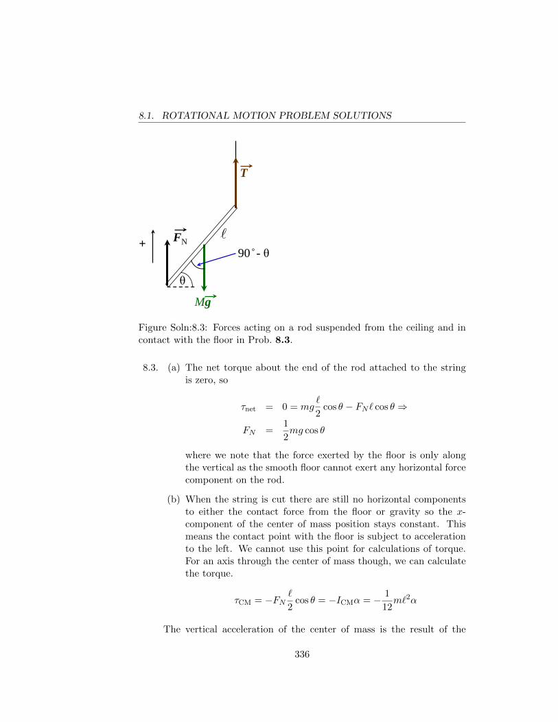
8.1. ROTATIONAL MOTION PROBLEM SOLUTIONS
Mg
T
+ FN 90 - θ
θ
Figure Soln:8.3: Forces acting on a rod suspended from the ceiling and incontact with the floor in Prob. 8.3.
8.3. (a) The net torque about the end of the rod attached to the stringis zero, so
τnet = 0 = mg`
2cos θ − FN` cos θ ⇒
FN =1
2mg cos θ
where we note that the force exerted by the floor is only alongthe vertical as the smooth floor cannot exert any horizontal forcecomponent on the rod.
(b) When the string is cut there are still no horizontal componentsto either the contact force from the floor or gravity so the x-component of the center of mass position stays constant. Thismeans the contact point with the floor is subject to accelerationto the left. We cannot use this point for calculations of torque.For an axis through the center of mass though, we can calculatethe torque.
τCM = −FN`
2cos θ = −ICMα = − 1
12m`2α
The vertical acceleration of the center of mass is the result of the
336
8.1. ROTATIONAL MOTION PROBLEM SOLUTIONS
normal force and gravity, so
FN −mg = −maCM = −m∣∣∣∣d2y(t)
dt2
∣∣∣∣assuming y is the vertical (up) direction and aCM is the magnitude ofthe acceleration of the CM. To relate the angular acceleration to thevertical acceleration we note that the vertical position of the floor asan origin determines that
y(t) =`
2sin θ(t)⇒
dy(t)
dt=
`
2cos θ(t)
dθ(t)
dt⇒
d2y(t)
dt2=
`
2
[− sin θ(t)
(dθ(t)
dt
)2
+ cos θ(t)d2θ(t)
dt2
]
For the time t = 0, we have the initial linear and angular velocity of
the CM as zero, so dθ(t)/dt
∣∣∣∣t=0
= 0. Hence, the vertical acceleration
of the CM of the rod at t = 0 is
d2y(t)
dt2
∣∣∣∣t=0
= −aCM = −α`2
cos θ.
We can use the force and torque equations to solve for aCM, i.e. thevertical acceleration.
FN =m`α
6 cos θ
=m`
6 cos θ· 2aCM
` cos θ
m(g − aCM) =m
3 cos2 θaCM ⇒
g = aCM
[1
3 cos2 θ+ 1
]⇒
aCM =3g cos2 θ
1 + 3 cos2 θ⇒ ~aCM = − 3g cos2 θ
1 + 3 cos2 θy
and the normal force is
~FN =maCM
3 cos2 θy =
mg
1 + 3 cos2 θy
337
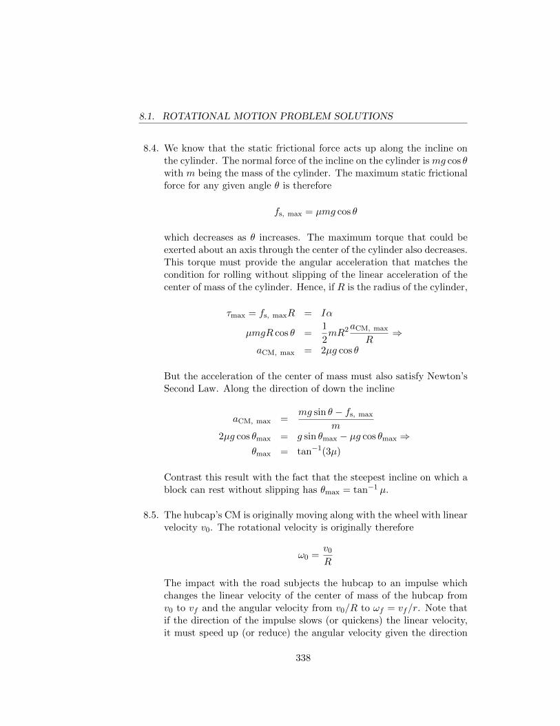
8.1. ROTATIONAL MOTION PROBLEM SOLUTIONS
8.4. We know that the static frictional force acts up along the incline onthe cylinder. The normal force of the incline on the cylinder is mg cos θwith m being the mass of the cylinder. The maximum static frictionalforce for any given angle θ is therefore
fs, max = µmg cos θ
which decreases as θ increases. The maximum torque that could beexerted about an axis through the center of the cylinder also decreases.This torque must provide the angular acceleration that matches thecondition for rolling without slipping of the linear acceleration of thecenter of mass of the cylinder. Hence, if R is the radius of the cylinder,
τmax = fs, maxR = Iα
µmgR cos θ =1
2mR2aCM, max
R⇒
aCM, max = 2µg cos θ
But the acceleration of the center of mass must also satisfy Newton’sSecond Law. Along the direction of down the incline
aCM, max =mg sin θ − fs, max
m2µg cos θmax = g sin θmax − µg cos θmax ⇒
θmax = tan−1(3µ)
Contrast this result with the fact that the steepest incline on which ablock can rest without slipping has θmax = tan−1 µ.
8.5. The hubcap’s CM is originally moving along with the wheel with linearvelocity v0. The rotational velocity is originally therefore
ω0 =v0
R
The impact with the road subjects the hubcap to an impulse whichchanges the linear velocity of the center of mass of the hubcap fromv0 to vf and the angular velocity from v0/R to ωf = vf/r. Note thatif the direction of the impulse slows (or quickens) the linear velocity,it must speed up (or reduce) the angular velocity given the direction
338
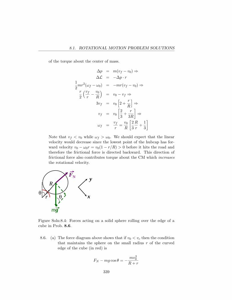
8.1. ROTATIONAL MOTION PROBLEM SOLUTIONS
of the torque about the center of mass.
∆p = m(vf − v0)⇒∆L = −∆p · r
1
2mr2(ωf − ω0) = −mr(vf − v0)⇒r
2
(vfr− v0
R
)= v0 − vf ⇒
3vf = v0
[2 +
r
R
]⇒
vf = v0
[2
3+
r
3R
]⇒
ωf =vfr
=v0
R
[2
3
R
r+
1
3
]Note that vf < v0 while ωf > ω0. We should expect that the linearvelocity would decrease since the lowest point of the hubcap has for-ward velocity v0 − ω0r = v0(1 − r/R) > 0 before it hits the road andtherefore the frictional force is directed backward. This direction offrictional force also contributes torque about the CM which increasesthe rotational velocity.
r
R
mg
FN
θ θ
y
x
Figure Soln:8.4: Forces acting on a solid sphere rolling over the edge of acube in Prob. 8.6.
8.6. (a) The force diagram above shows that if v0 < vc then the conditionthat maintains the sphere on the small radius r of the curvededge of the cube (in red) is
FN −mg cos θ = − mv20
R+ r
339
8.1. ROTATIONAL MOTION PROBLEM SOLUTIONS
This is the centripetal condition required for a circular path. As-suming that r � R we can ignore r and just assume the radius ofthe curved path is just R the radius of the sphere. The definitionof “maintain contact” is that the normal force not be zero, so ifthe initial velocity of the center of mass of the sphere is too high,FN would have to be less than zero (non-physical!) to satisfy theequation. Hence the sphere leaves the cube without any devia-tion in the direction of ~v0. Therefore we want to evaluate vc forθ = 0.
mg cos θ − mv2c
R= 0⇒ vc =
√Rg cos θ =
√Rg
(b) Now we allow for θ > 0. The linear velocity of the center of massand the angular velocity about the center of mass increase as thesphere’s center drops as it rolls over the edge. The initial kineticenergy can be calculated as
K0 =1
2mv2
0 +1
2Iω2
CM
=1
2mv2
0 +1
2· 2
5mR2 · v
20
R2
K0 =7
10mv2
0
It is more convenient to consider the motion as pure rotationabout the stationary point (assumes no slipping!) of contact ofthe sphere with the cube edge. Then, using the parallel-axistheorem and the rolling without slipping condition that angularspeed around the center of mass is the same as angular speed ofthe center of mass around the axis through the point of rollingcontact, we have
K0 =1
2Iedgeω
2edge
=1
2
(2
5mR2 +mR2
)v2
0
R2
K0 =7
10mv2
0
The speed increases as the sphere rolls over the edge as the centerof mass goes down. Considering the cube’s top surface as the zero
340
8.1. ROTATIONAL MOTION PROBLEM SOLUTIONS
point of the vertical position, we calculate this increase in speedas
−∆U = mgR−mgR cos θ = ∆K =7
10mv2
f −7
10mv2
0 ⇒
gR(1− cos θ) =7
10v2f −
7
10v2
0
From our analysis in part a of this problem, we know that thereis a maximum speed corresponding to maintaining contact, i.e.when the normal force goes to zero.
FN −mg cos θ = −mv2
R⇒
0−mg cos θc = −mv2
f
R⇒
v2f = gR cos θ
Plugging this into our previous energy equation, we see
gR(1− cos θc) =7
10gR cos θc −
7
10v2
0 ⇒17
10gR cos θc = gR+
7
10v2
0 ⇒
θc = cos−1
[7
17
v20
gR+
10
17
](c) As before, the normal force goes to zero at the critical angle θc,
so if v0 = 0, the formula from part b gives us
θc = cos−1 10
17= 54.0◦
(d) Consider Fig.Soln:8.5 where we show the sphere just leaving theedge of the cube. We know the critical angle θc for which thishappens if v0 = 0. From the figure we see that if, in the time ittakes for the sphere’s center of mass to travel horizontally by adistance ∆x, the sphere has traveled down vertically less than adistance ∆y = R cos θ, then the left edge of the sphere misses thelast point of contact of sphere and cube and therefore there is nobump. The free-fall formulae for the center of mass are
∆x = vCM cos θc(∆t)
∆y = vCM sin θc(∆t) +1
2g(∆t)2
341
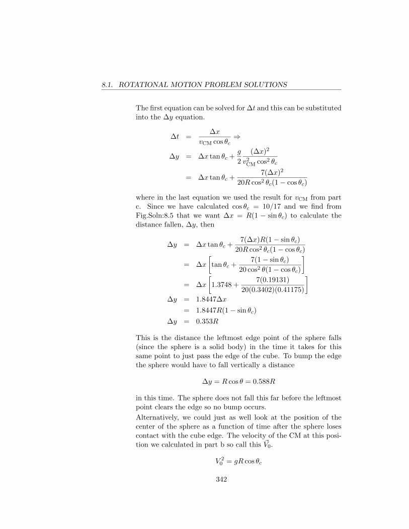
8.1. ROTATIONAL MOTION PROBLEM SOLUTIONS
The first equation can be solved for ∆t and this can be substitutedinto the ∆y equation.
∆t =∆x
vCM cos θc⇒
∆y = ∆x tan θc +g
2
(∆x)2
v2CM cos2 θc
= ∆x tan θc +7(∆x)2
20R cos2 θc(1− cos θc)
where in the last equation we used the result for vCM from partc. Since we have calculated cos θc = 10/17 and we find fromFig.Soln:8.5 that we want ∆x = R(1 − sin θc) to calculate thedistance fallen, ∆y, then
∆y = ∆x tan θc +7(∆x)R(1− sin θc)
20R cos2 θc(1− cos θc)
= ∆x
[tan θc +
7(1− sin θc)
20 cos2 θ(1− cos θc)
]= ∆x
[1.3748 +
7(0.19131)
20(0.3402)(0.41175)
]∆y = 1.8447∆x
= 1.8447R(1− sin θc)
∆y = 0.353R
This is the distance the leftmost edge point of the sphere falls(since the sphere is a solid body) in the time it takes for thissame point to just pass the edge of the cube. To bump the edgethe sphere would have to fall vertically a distance
∆y = R cos θ = 0.588R
in this time. The sphere does not fall this far before the leftmostpoint clears the edge so no bump occurs.
Alternatively, we could just as well look at the position of thecenter of the sphere as a function of time after the sphere losescontact with the cube edge. The velocity of the CM at this posi-tion we calculated in part b so call this ~V0.
V 20 = gR cos θc
342
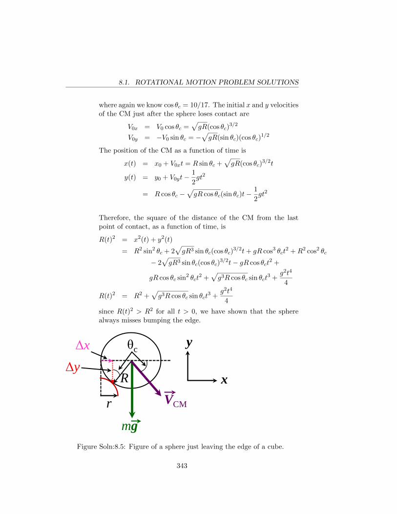
8.1. ROTATIONAL MOTION PROBLEM SOLUTIONS
where again we know cos θc = 10/17. The initial x and y velocitiesof the CM just after the sphere loses contact are
V0x = V0 cos θc =√gR(cos θc)
3/2
V0y = −V0 sin θc = −√gR(sin θc)(cos θc)
1/2
The position of the CM as a function of time is
x(t) = x0 + V0xt = R sin θc +√gR(cos θc)
3/2t
y(t) = y0 + V0yt−1
2gt2
= R cos θc −√gR cos θc(sin θc)t−
1
2gt2
Therefore, the square of the distance of the CM from the lastpoint of contact, as a function of time, is
R(t)2 = x2(t) + y2(t)
= R2 sin2 θc + 2√gR3 sin θc(cos θc)
3/2t+ gR cos3 θct2 +R2 cos2 θc
− 2√gR3 sin θc(cos θc)
3/2t− gR cos θct2 +
gR cos θc sin2 θct2 +
√g3R cos θc sin θct
3 +g2t4
4
R(t)2 = R2 +√g3R cos θc sin θct
3 +g2t4
4
since R(t)2 > R2 for all t > 0, we have shown that the spherealways misses bumping the edge.
r
R
mg
θc y
x VCM
Δy Δx
Figure Soln:8.5: Figure of a sphere just leaving the edge of a cube.
343
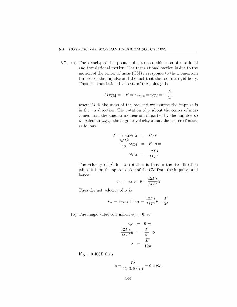
8.1. ROTATIONAL MOTION PROBLEM SOLUTIONS
8.7. (a) The velocity of this point is due to a combination of rotationaland translational motion. The translational motion is due to themotion of the center of mass (CM) in response to the momentumtransfer of the impulse and the fact that the rod is a rigid body.Thus the translational velocity of the point p′ is
MvCM = −P ⇒ vtrans = vCM = − PM
where M is the mass of the rod and we assume the impulse isin the −x direction. The rotation of p′ about the center of masscomes from the angular momentum imparted by the impulse, sowe calculate ωCM, the angular velocity about the center of mass,as follows.
L = ICMωCM = P · sML2
12ωCM = P · s⇒
ωCM =12Ps
ML2
The velocity of p′ due to rotation is thus in the +x direction(since it is on the opposite side of the CM from the impulse) andhence
vrot = ωCM · y =12Ps
ML2y
Thus the net velocity of p′ is
vp′ = vtrans + vrot =12Ps
ML2y − P
M
(b) The magic value of s makes vp′ = 0, so
vp′ = 0⇒12Ps
ML2y =
P
M⇒
s =L2
12y
If y = 0.400L then
s =L2
12(0.400L)= 0.208L
344
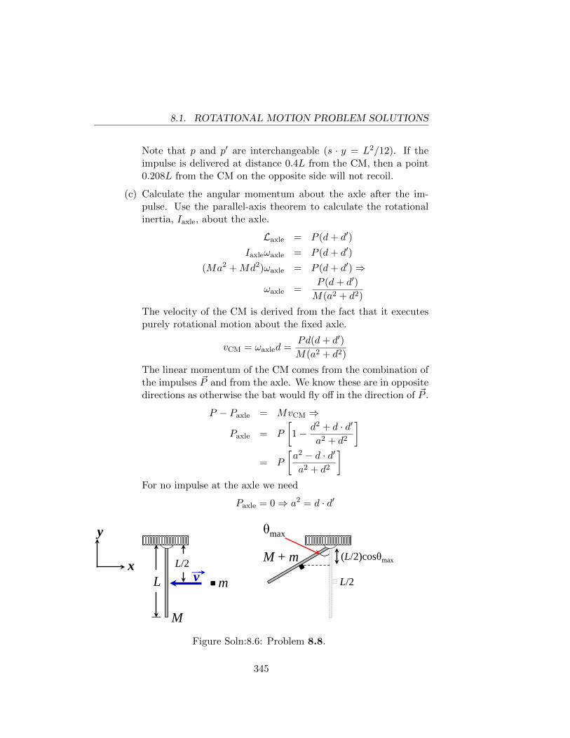
8.1. ROTATIONAL MOTION PROBLEM SOLUTIONS
Note that p and p′ are interchangeable (s · y = L2/12). If theimpulse is delivered at distance 0.4L from the CM, then a point0.208L from the CM on the opposite side will not recoil.
(c) Calculate the angular momentum about the axle after the im-pulse. Use the parallel-axis theorem to calculate the rotationalinertia, Iaxle, about the axle.
Laxle = P (d+ d′)
Iaxleωaxle = P (d+ d′)
(Ma2 +Md2)ωaxle = P (d+ d′)⇒
ωaxle =P (d+ d′)
M(a2 + d2)
The velocity of the CM is derived from the fact that it executespurely rotational motion about the fixed axle.
vCM = ωaxled =Pd(d+ d′)
M(a2 + d2)
The linear momentum of the CM comes from the combination ofthe impulses ~P and from the axle. We know these are in oppositedirections as otherwise the bat would fly off in the direction of ~P .
P − Paxle = MvCM ⇒
Paxle = P
[1− d2 + d · d′
a2 + d2
]= P
[a2 − d · d′
a2 + d2
]For no impulse at the axle we need
Paxle = 0⇒ a2 = d · d′
L
y
x v
L/2
m
M
M + m (L/2)cosθmax
θmax
L/2
Figure Soln:8.6: Problem 8.8.
345
8.1. ROTATIONAL MOTION PROBLEM SOLUTIONS
8.8. (a) The collision is inelastic so mechanical energy is not conserved.The hinge exerts external forces on the rod so the linear momen-tum of the rod and clay is not conserved in the collision either.Angular momentum of the rod and clay about an axis through thehinge and perpendicular to the x− y plane is conserved since thehinge can apply no torque about that axis. The angular velocityjust after the collision is therefore calculable as follows.
Linitial = Lfinal = Itotalω
mv · L2
=
[Irod about end +m ·
(L
2
)2]ω
mvL
2=
[1
3ML2 +
1
4mL2
]ω ⇒
ω =6mv
L[4M + 3m]
After the collision, rotational mechanical energy is conserved asagain the hinge provides no external torque for an axis throughthe hinge and gravity acting on the center of the mass of the sys-tem of rod and clay is conservative. So we can find the maximumangle of swing from equilibrium as follows:
∆K = −∆Ugrav
0− 1
2Itotalω
2 = −(m+M)gL
2(1− cos θmax)⇒
3m2v2
2(4M + 3m)=
1
2(m+M)gL (1− cos θmax)⇒
θmax = cos−1
[1− 3m2v2
gL(m+M)(3m+ 4M)
]Note: what happens if the term in the square brackets is less than−1? In that case the rod would rotate full circle forever (if theceiling weren’t there).
(b) Gravity plays no role in the collision since it is a finite force (andcan therefore produce no impulse) and even if it could producean impulse that impulse would be orthogonal to the momentumchange in this problem.
346
8.1. ROTATIONAL MOTION PROBLEM SOLUTIONS
We take our system to consist of the rod and clay. The linearmomentum of the system just before the collision is
~pinitial = mvi
and just after the collision
~pafter = (M +m)~VCM
= (M +m)L
2ωi
~pafter =M +m
4M + 3m(3mv)i
The only external impulse on the system is exerted by the hinge.Call this impulse ∆~phinge. Then
∆~phinge = ~pafter − ~pinitial
= mv
[3(M +m)
3m+ 4M− 1
]i
= − mMv
3m+ 4Mi
The impulse given by the rod to the hinge is
∆~phinge =mMv
3m+ 4Mi
We should note that the total impulse given to the hinge by therod and ceiling is zero.
347
8.1. ROTATIONAL MOTION PROBLEM SOLUTIONS
348
Appendix 9
Remarks on Gravitation
9.1 Remarks on Gravity Problem Solutions
9.1. The kinetic energy of a circular orbit is half the gravitational potentialenergy of the orbit. So
K + U =1
2U ⇒
K = −1
2U =
GMEm
2(RE + 3.00× 10⁵ m)⇒
v =
√GME
RE + 3.00× 105
=
√(6.67× 10⁻¹¹ m3/(kg · s2)) (5.97× 1024 kg)
6.67× 10⁶ m
v = 7.73× 10³ m/s
The period of such an orbit is easy to get from Kepler’s Third Law.
period =
[4π2r3
GME
]1/2
=
[4(3.14159)2
(6.67× 10⁶
)3(6.67× 10⁻¹¹ m3/(kg · s2)) (5.97× 1024 kg)
]1/2
period = 5420 s = 1.51 hours
9.2. (a) The orbit diagram for this case is as follows: The Hohmann or-
349
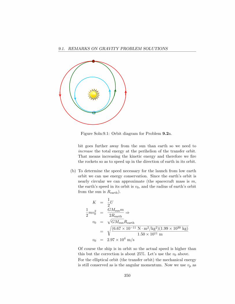
9.1. REMARKS ON GRAVITY PROBLEM SOLUTIONS
Figure Soln:9.1: Orbit diagram for Problem 9.2a.
bit goes further away from the sun than earth so we need toincrease the total energy at the perihelion of the transfer orbit.That means increasing the kinetic energy and therefore we firethe rockets so as to speed up in the direction of earth in its orbit.
(b) To determine the speed necessary for the launch from low earthorbit we can use energy conservation. Since the earth’s orbit isnearly circular we can approximate (the spacecraft mass is m,the earth’s speed in its orbit is v0, and the radius of earth’s orbitfrom the sun is Rearth).
K =1
2U
1
2mv2
0 =GMsunm
2Rearth⇒
v0 =√GMsunRearth
=
√(6.67× 10⁻¹¹ N ·m2/kg2)(1.99× 1030 kg)
1.50× 10¹¹ m
v0 = 2.97× 10⁴ m/s
Of course the ship is in orbit so the actual speed is higher thanthis but the correction is about 25%. Let’s use the v0 above.
For the elliptical orbit (the transfer orbit) the mechanical energyis still conserved as is the angular momentum. Now we use vp as
350
9.1. REMARKS ON GRAVITY PROBLEM SOLUTIONS
the speed of the probe relative to the sun at the perihelion point(the launch from earth).
Eperihelion = Eaphelion ⇒1
2mv2
peri −GMsun
Rearth=
1
2mv2
aph −GMsunm
RMars
Lperi = Laph
mvperiRearth = mvaphRMars ⇒
vaph = vperiRearth
RMars
Combining the angular momentum result with the energy con-servation result, we see that
1
2v2
peri −GMsun
Rearth=
1
2v2
peri
R2earth
R2Mars
− GMsun
RMars⇒
v2peri
[R2
Mars −R2Mars
2R2Mars
]= GMsun
[RMars −Rearth
RearthRMars
]⇒
vperi =
√GMsun
2RMars
Rearth(RMars +Rearth)
=
√2(6.67× 10⁻¹¹ N ·m2/kg2)(1.99× 1030 kg)(2.28× 10¹¹ m)
(1.50× 10¹¹ m)(2.28 + 1.50)× 1011 m
vperi = 3.27× 10⁴ m/s
So the launch speed must be
vlaunch = (3.27− 2.97)× 104 m/s = 2.93× 10³ m/s ' 3 km/s
To get the time needed we can just take advantage of our deriva-tion of Kepler’s Third Law for elliptical orbits.
T =1
2
√4π2
GMsun
[rearth + rMars
2
]2
=
√(3.141593)2(3.78× 10¹¹ m)3
8(6.67× 10⁻¹¹ N ·m2/kg2)(1.99× 1030 kg)
T = 2.24× 10⁷ s ' 8.5 months
351
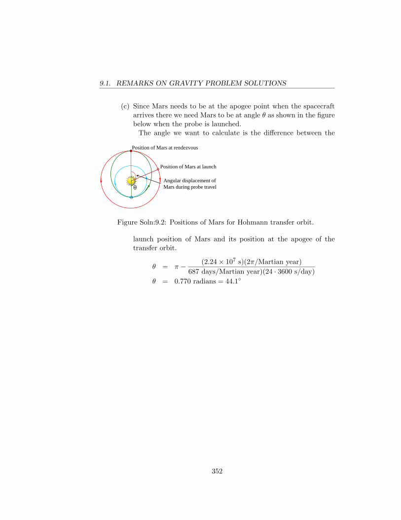
9.1. REMARKS ON GRAVITY PROBLEM SOLUTIONS
(c) Since Mars needs to be at the apogee point when the spacecraftarrives there we need Mars to be at angle θ as shown in the figurebelow when the probe is launched.
The angle we want to calculate is the difference between the
θ
Position of Mars at rendezvous
Position of Mars at launch
Angular displacement of Mars during probe travel
Figure Soln:9.2: Positions of Mars for Hohmann transfer orbit.
launch position of Mars and its position at the apogee of thetransfer orbit.
θ = π − (2.24× 10⁷ s)(2π/Martian year)
687 days/Martian year)(24 · 3600 s/day)
θ = 0.770 radians = 44.1◦
352
Bibliography
[HB01] Gerald Holton and Stephen G. Brush, From copernicus to ein-stein and beyond, Addison-Wesley, Rutgers University Press, Pis-cataway, NJ, 2001.
[MS82] S. Aoki B. Guinot G.H. Kaplan H. Kinoshita D.D. McCarthy andP.K. Seidelmann, The new definition of universal time, Astronomyand Astrophysics 105(2) (1982), 361.
[New] Isaac Newton, Principia Mathematica, edited, with commen-tary by Stephen Hawking, Google Books reference, available athttp://books.google.com/books.
[New02] , Principia Mathematica, Running Press Book Publish-ers, 125 South Twenty-second Street, Philadelphia, PA 19103-4399,2002.
[Noo01] Randall K. Noon, Forensic engineering investigation, CRC PressLLC, 2000 N.W. Corporate Blvd, Boca Raton, FL 33431, 2001.
[oST10] National Institute of Standards and Technology, Digital libraryof mathematical functions, Cambridge University Press, UPH,Shaftesbury Road, Cambridge, CB2 8BS, United Kingdom, 2010.
[Ph.00] A. Stanley Mackenzie Ph.D., The laws of gravitation: Memoirs bynewton, bouguer and cavendish, American Book Company, PO Box2638, Woodstock, GA 20188-1383, 1900.
[Sta] NASA Staff, Solar system exploration - earth’s moon: Facts &figures, Retrieved 2012-09-29.
[TN] P.J. Mohr B.N. Taylor and D.B. Newell, The 2010 codata recom-mended values of the fundamental physical constants, National In-situte of Standards and Technology, Gaithersburg, MD 20899.
353
BIBLIOGRAPHY BIBLIOGRAPHY
[Val45] Paul Valery, Regards sur le monde actuel et autres essais, Paris:Gallimard, 5, rue Gaston-Gallimard, 75328 Paris cedex 07, 1945.
354
Index
amplitude, 160angular acceleration, 201angular frequency, 160angular momentum, 195associative, 252Atwood’s machine, 76average acceleration, 6average force, 115average velocity, 2average x-velocity, 11
calorie, 150center of mass, 111, 208center-of-mass system, 146central force, 94central forces, 178centrifugal force, 87centripetal acceleration, 14centripetal force, 86circle of reference, 163coefficient of kinetic friction, 63coefficient of static friction, 55commutative, 252completely inelastic, 144completely inelastic collision, 108components of the position vector, 11conic sections, 240Conservation of Energy, 142conservative, 139constant acceleration, 9cross product, 256
determinate, 190
dimensional analysis, 170displacement, 250distributive, 253dot product, 255drift velocity, 144dynamic balancing, 115
eccentricity, 243elastic, 144electrostatic force, 178equation of motion, 195, 241equilibrium, 32, 155equilibrium position, 155escape velocity, 141
food calories, 150foot-pound, 149force, 26free-body diagram, 34frequency, 114, 160frictional, 27frictional force, 52
geoid, 238gravitation, 97gravitational constant, 96gravitational potential energy, 138
Hooke’s Law, 156hoop, 201horsepower, 149
ideal rocket equation, 120
355
INDEX INDEX
impact parameter, 149impulse, 220impulsive, 220inelastic, 144inertial frame, 199inertial frames, 28instantaneous velocity, 2
joule, 149
Kepler’s Second Law, 196Kinematics, 1kinetic energy, 127, 142
latus rectum, 243Law of Universal Gravitation, 235line integral, 126
mass, 70maximally inelastic, 144mechanical advantage, 48moment of inertia, 201, 217, 263
newton, 33, 70Newton’s Third Law of Motion, 38non-conservative, 140normal, 27
parallel axis theorem, 263parallel translation, 251pendulum, 166position vector, 11potential energy, 137, 140, 142pound, 33power, 149Principle of Conservation of Energy,
137, 140, 142Principle of Conservation of Momen-
tum, 106, 143
quantum mechanics, 143
rate of change of velocity, 6reference point, 140rigid body, 223rolling without slipping, 211rotational inertia, 201rotational power, 222rotational work, 222
scalar product, 255semi-major axis, 243sidereal day, 100simple harmonic motion, 155slope, 3slug, 70spring constant, 156statically balancing, 114statically indeterminate, 190sweet spot, 233
tension, 35, 44torque, 175, 176total mechanical energy, 137, 142total work, 137trajectory, 16
uniform circular motion, 12uniform rod, 202unit vector, 256
vector addition, 251vector notation, 11vector product, 256vectors, 249
watt, 149wattage, 149weight, 33work, 125Work-Energy Theorem, 125, 127
356


![Classical Mechanics - people.phys.ethz.chdelducav/cmscript.pdf · References [1]LandauandLifshitz,Mechanics,CourseofTheoreticalPhysicsVol.1., PergamonPress [2]Classical Mechanics,](https://static.fdocuments.us/doc/165x107/5e1e9832bac1ea74484e9601/classical-mechanics-delducavcmscriptpdf-references-1landauandlifshitzmechanicscourseoftheoreticalphysicsvol1.jpg)


![[Kibble] - Classical Mechanics](https://static.fdocuments.us/doc/165x107/552056344a79596f718b4715/kibble-classical-mechanics.jpg)