City of San Mateo Clean Water Program Control System PLC ...
148
City of San Mateo Clean Water Program Control System PLC Programming Standards Revision 3 Prepared for City of San Mateo JULY, 2017 Prepared by CH2M
Transcript of City of San Mateo Clean Water Program Control System PLC ...

City of San Mateo Clean Water Program Control System PLC Programming
Standards Revision 3
Prepared for
City of San Mateo JULY, 2017
Prepared by CH2M

SAN_MATEO_PLC_PROGRAM_STANDARDS_REV3 ii V 1.2 April 16, 2010
Contents
Section Page 1.0 Introduction ......................................................................................................................... 1-1
1.1 Purpose .................................................................................................................... 1-1 1.1.1 Target Audience ........................................................................................ 1-1
1.2 Hardware Standards .............................................................................................. 1-1 1.2.1 General ........................................................................................................ 1-1 1.2.2 Large Control System Components ........................................................ 1-2
1.3 PLC Software Standards ........................................................................................ 1-3
2.0 PLC Software Development ............................................................................................. 2-1 2.1 Program Structure .................................................................................................. 2-1 2.2 IO Configuration .................................................................................................... 2-1
2.2.1 Ethernet Card Configuration – ControlLogix ....................................... 2-2 2.2.2 ControlNet Card Configuration – ControlLogix .................................. 2-2 2.2.3 DeviceNet Card Configuration – ControlLogix .................................... 2-3 2.2.4 Analog Input Card Configuration – ControlLogix ............................... 2-3 2.2.5 Analog Output Card Configuration – ControlLogix............................ 2-4 2.2.6 Digital Input Card Configuration – ControlLogix ................................ 2-5 2.2.7 Digital Output Card Configuration – ControlLogix ............................ 2-5
2.3 PLC Tag Database .................................................................................................. 2-5 2.3.1 Controller Scope and Program Scope ..................................................... 2-6 2.3.2 Base Tags and Alias Tags ......................................................................... 2-6 2.3.3 Produced Tags and Consumed Tags ...................................................... 2-7
2.4 PLC Control Code .................................................................................................. 2-7 2.4.1 Tasks ............................................................................................................ 2-8 2.4.2 Programs ..................................................................................................... 2-9 2.4.3 Routines ...................................................................................................... 2-9
3.0 Tagging/Naming Conventions......................................................................................... 3-1 3.1 PLC Naming Conventions .................................................................................... 3-1
3.1.1 PLC File and Controller Names .............................................................. 3-1 3.1.2 PLC Hardware Names (Communication and IO modules) ................ 3-1 3.1.3 ControlLogix Task Names ....................................................................... 3-2 3.1.4 ControlLogix Program File Names ......................................................... 3-2 3.1.5 ControlLogix Routine Names .................................................................. 3-2
3.2 PLC Software Tagging Criteria ............................................................................ 3-3 3.2.1 Tagging Overview ..................................................................................... 3-3 3.2.2 Tag Numbering Format ............................................................................ 3-3
4.0 User-Defined Elements ..................................................................................................... 4-1 4.1 General ..................................................................................................................... 4-1
4.1.1 User Data Type .......................................................................................... 4-1 4.2 Add-On Instructions .............................................................................................. 4-4
CONTENTS
SAN_MATEO_PLC_PROGRAM_STANDARDS_REV3 iii JULY, 2017
5.0 PLC Program Documentation .......................................................................................... 5-1 5.1 Routine Documentation ........................................................................................ 5-1 5.2 Tag Descriptions ..................................................................................................... 5-2
6.0 PLC Program Development .............................................................................................. 6-1 6.1 General ..................................................................................................................... 6-1 6.2 Tags and Data ......................................................................................................... 6-2
6.2.1 Analog Input Data ..................................................................................... 6-4 6.2.2 Messaging Data between PLCs ............................................................... 6-4 6.2.3 Standard Program Structure .................................................................... 6-5
7.0 PLC Programming Best Practices .................................................................................... 7-1 7.1 Simplify Rungs of Code ......................................................................................... 7-1 7.2 Data Types ............................................................................................................... 7-2 7.3 Prefacing Conditions .............................................................................................. 7-2 7.4 Discrete Controls .................................................................................................... 7-3 7.5 Equations ................................................................................................................. 7-3 7.6 Timers....................................................................................................................... 7-3 7.7 Counters ................................................................................................................... 7-4 7.8 Button Control ........................................................................................................ 7-5 7.9 Sequence Control .................................................................................................... 7-6 7.10 PID Control ............................................................................................................. 7-6 7.11 SCADA Set points .................................................................................................. 7-6 7.12 Alarming .................................................................................................................. 7-7
8.0 Glossary ................................................................................................................................ 8-1 Tables Table 4-1 Approved UDT ................................................................................................................ 4-3
Figures Figure 2-1 Sample IO Configuration .............................................................................................. 2-2 Figure 2-2 Sample Program Configuration ................................................................................... 2-8 Figure 4-1 Sample Non-optimized UDT Configuration ............................................................. 4-2 Figure 4-2 Sample Optimized UDT Configuration ..................................................................... 4-2 Figure 4-3 Sample Tag ..................................................................................................................... 4-4 Figure 4-4 Access to Add-On Instructions .................................................................................... 4-5 Figure 5-1 Sample Ladder Routine ................................................................................................ 5-1 Figure 5-2. Sample Function Block Routine .................................................................................. 5-2 Figure 5-4 Sample Tag Descriptions and Tag Names ................................................................. 5-3 Figure 6-3. Analog Tag Aliased to Analog Input Card ............................................................... 6-4 Figure 7-1 Complicated Rungs of Ladder Code ........................................................................... 7-1 Figure 7-2 Simplified Rungs of Ladder Code ............................................................................... 7-2 Figure 7-3 Prefacing Conditions in Ladder ................................................................................... 7-3 Figure 7-5 Counter Using CTU ....................................................................................................... 7-4 Figure 7-6 Counter Using ADD ...................................................................................................... 7-5 Figure 7-7 Two-State Toggle Control ............................................................................................. 7-5

CONTENTS
SAN_MATEO_PLC_PROGRAM_STANDARDS_REV3 iv JULY, 2017
Figure 7-8 Sample SCADA Setpoints............................................................................................. 7-7 Figure 7-9 Sample Alarm Cascading Interlock............................................................................. 7-7

SAN_MATEO_PLC_PROGRAM_STANDARDS_REV3 v AUGUST 2016
Acronyms and Abbreviations
A/M auto/manual
A-B Allen-Bradley
AI analog input
AO analog output
AOI Add-On Instruction
BOOL Boolean
cfm cubic feet per minute
CPR Coordinated Product Release
CPT compute block
CV control variable
DI discrete input
DINT double integer – 32 bits
DO discrete output
FB function block
ft3/minute cubic feet per minute
FVNR full-voltage non-reversing
FVR full-voltage reversing
gph gallons per hour
gpm gallons per minute
GUI graphical user interface
HMI human-machine interface
INT integer – 16 bits
IO Input / Output
JSR jump to subroutine command
LAD ladder
mgd million gallons per day
MSG message commands
NOP No Operation Command
ODVA Open DeviceNet Vendors Association

ACRONYMS AND ABBREVIATIONS
SAN_MATEO_PLC_PROGRAM_STANDARDS_REV3 vi JULY, 2017
PCS Process Control System
PID Proportional Integral Derivative
P&ID process and instrumentation diagram
PLC programmable logic controller
PV process variable
RTH run time hours
SCADA Supervisory Control and Data Acquisition
SFC sequential function chart
SINT single integer – 8 bits
SP Set point
ST structured text
T&D treatment and disposal
TBD to be determined
UDT User-defined Data Type
VSD variable-speed drive

SAN_MATEO_PLC_PROGRAM_STANDARDS_REV3 1-1 AUGUST 2016
1.0 Introduction
1.1 Purpose The purpose of this document is to establish the City of San Mateo enterprise-wide programmable logic controller (PLC) program standards as applied to plant control systems utilizing Allen-Bradley (A-B) ControlLogix hardware. Hardware and software standards are needed to provide uniformity across multiple control system projects. Specific goals include:
• Provide a common structure and program development methodology for all PLC programs
• Define standards for PLC program development as applied to A-B ControlLogic hardware platforms.
• Reduce installation and maintenance of both PLC and human-machine interface (HMI) programs thus reducing the City’s operating expenses and capital expenditures.
For further reference and additional information, please refer to the following documents.
• City of San Mateo Clean Water Program Control System HMI Programming Standards • City of San Mateo Clean Water Program Design Standard 05 – Equipment and Instrument
Identification Standards
1.1.1 Target Audience It is expected that users of this document will have a general knowledge of PLC based control systems and a working knowledge of the A-B ControlLogix hardware platforms. In addition, users should have a working knowledge of the Common Industrial Protocol (CIP) communications including their configuration and operation.
1.2 Hardware Standards 1.2.1 General The City of San Mateo control system is based on the A-B ControlLogix Redundant PLC for primary control, which is the latest in the progression of A-B control hardware. Field devices such as motors, valves, and instruments will interface to the control system through a series of IO racks. Field device interface can be hardwired between the field device and an IO module, providing individual equipment signals per wire set. Or signals can be networked between field devices and a communication module providing for multiple equipment signals per wire set.
The system will use several modes of communication to achieve the required system functionality, including the following.

1.0 INTRODUCTION
SAN_MATEO_PLC_PROGRAM_STANDARDS_REV3 1-2 JULY, 2017
• Ethernet IP Communications: The Ethernet network will provide the connection between PLCs and the Supervisory Control And Data Acquisition (SCADA) system. In addition, PLC-to-PLC communications will primarily use the Ethernet network.
• ControlNet Communications: Remote racks (a rack housing communications and/or IO modules but not including a CPU) can communicate with their parent PLC via a ControlNet communications network. For control systems utilizing ControlNet communications, the primary input/output (IO) rack (IO rack containing a CPU) will include at least one ControlNet communications module. The primary IO rack can contain multiple ControlNet communications modules providing for multiple ControlNet networks for a single CPU. All remote IO racks included in the ControlNet system will then include one ControlNet communications module to be located in the first slot of the rack (slot 0).
− Non-redundant PLC systems: ControlNet module in primary rack will be configured as the ControlNet network master and include the lowest node number on the network.
− Redundant PLC systems: ControlNet modules in primary redundant racks will NOT be configured as the ControlNet network master. Node numbers for redundant CPU racks to be configured to reduce the likelihood of redundant rack ControlNet modules becoming the network master.
• DeviceNet Communications: Any device which complies with the Open DeviceNet Vendors Association (ODVA) open protocol standards for DeviceNet devices can be integrated into a DeviceNet network installed as part of a the City’s facility control system. For the City’s wastewater treatment facilities, this will primarily include (but not be limited to) adjustable speed drives. DeviceNet communication modules can reside in a primary PLC rack or in PLC remote racks. Multiple DeviceNet networks can be included within a facility control system. The design intent is to limit the number of nodes on any single network to 32 devices. In addition to ASDs, most motorized and control valves could also be controlled via a DeviceNet network.
Stand-alone control systems provided as part of a vendor package system or control systems with minimal IO may be classified as a small control system if the total number of modules (IO and communications) does not exceed 7. Control systems fitting these criteria will have the option of using the Allen-Bradley CompactLogix platform. All other PLC hardware shall be based on the standard control system equipment. All PLC-based control systems implemented for the City projects will use approved hardware selected from the lists in the adjoining sections.
1.2.2 Large Control System Components All A-B control hardware and software will be Coordinated Product Release 9 (CPR9) compliant. Hardware module types and firmware revision numbers indicated below are minimum base requirements. The actual modules used in a system shall be based upon the project specific design and specifications. Any deviation from the following listed components must be approved by the City prior to being used. The base design is based upon the 16 point DI card, but the 32 point DI card can be used at the discretion of the City.

1.0 INTRODUCTION
SAN_MATEO_PLC_PROGRAM_STANDARDS_REV3 1-3 JULY, 2017
All modules will have firmware set to most current revision number that is compatible with the version of the Enhanced Redundancy Module used in the base project (V27), provided that the latest firmware revisions maintain compatibility with existing systems. Ensure all software revisions and patch levels are at the same level throughout the integrated system.
1.3 PLC Software Standards The following standard software packages are required to develop plant control system PLC programs and meet standards developed by the City.
Rockwell Automation – RSLogix5000 Version 27 Rockwell Automation – RSNetworx for DeviceNet Version 21.01.00 Rockwell Automation – RSNetworx for ControlNet Version 21.01.00 Rockwell Automation – ControlFlash Version 12.00.00
NOTE: ControlFlash software is used to flash the firmware revisions of ControlLogix and CompactLogix cards to the desired level. The latest firmware files can be found at: http://support.rockwellautomation.com/ControlFlash/. For ControlLogix, the processor flash firmware must be updated lock-step with the RSLogix 5000 version. For other modules, you only need to update the flash firmware if you want the new feature/functionality described in the release note. It is not recommend updating these other modules ahead of the programming software as it may not be compatible. The manual for using ControlFlash can be found at: http://literature.rockwellautomation.com/idc/groups/literature/documents/qs/1756-qs105_-en-e.pdf.

SAN_MATEO_PLC_PROGRAM_STANDARDS_REV3 2-1 AUGUST 2016
2.0 PLC Software Development
2.1 Program Structure An A-B ControlLogix PLC program includes three main components, which work together to form the overall PLC program. The components of the PLC program include:
• IO configuration • PLC program internal tag database • Control code
2.2 IO Configuration The IO configuration provides a map for the CPU to define modules (IO and communication) included in the control system as well as their locations within the system. The IO configuration also serves to tell the CPU what version of hardware is being used in the control system and to set the data transfer rate between the CPU and the modules. The IO configuration is based on design documents created by the design Engineers for the control system. Design documents can include:
• Process and instrumentation diagram (P&IDs) • Process control narratives • Control system layout drawings • IO list
Configuration of the system is done by the programmer at the start of system programming. Configuration entails selecting modules, placing modules in appropriate locations, providing suitable module names, and setting module parameters.
The sample configuration in Figure 2-1, Sample I/O Configuration, shows the CPU at slot [0] and includes a default indication of device type (1756-L61) and a programmer-assigned name (_59PLC100). Remaining modules include communications and IO modules.
The following sections detail the standard configuration settings for each major type of module based on the module types specified in Section 1.2. Any deviations from the standard configuration must be approved by The City prior to system development.

2.0 PLC SOFTWARE DEVELOPMENT
SAN_MATEO_PLC_PROGRAM_STANDARDS_REV3 2-2 JULY, 2017
Figure 2-1 Sample IO Configuration
2.2.1 Ethernet Card Configuration – ControlLogix Each Ethernet module will include the following configuration settings.
Ethernet Card Configuration Settings General Tab
IP Address As Assigned by the City of San Mateo Revision 4 Electronic Keying Compatible Keying
Connection Tab Requested Packet Interval N/A Inhibit Module Not Checked Major Fault On Controller If… Not Checked
2.2.2 ControlNet Card Configuration – ControlLogix Each ControlNet module will include the following configuration settings.
ControlNet Card Configuration Settings General Tab
Comm Format Rack Optimized (for Remote Racks) Node As Assigned Revision 20.11 Electronic Keying Compatible Keying
Connection Tab Requested Packet Interval 100 ms

2.0 PLC SOFTWARE DEVELOPMENT
SAN_MATEO_PLC_PROGRAM_STANDARDS_REV3 2-3 JULY, 2017
ControlNet Card Configuration Settings Inhibit Module Not Checked Major Fault On Controller If… Not Checked
Refer to the Rockwell Software ControlNet module user guide for information on network configuration (PN 957988-68).
2.2.3 DeviceNet Card Configuration – ControlLogix Each DeviceNet module will include the following configuration settings.
DeviceNet Card Configuration Settings General Tab
Node 1 Revision 11 Electronic Keying Compatible Keying Input Size 124 Output Size 123 Status Size 32
Connection Tab Requested Packet Interval 100 ms Inhibit Module Not Checked Major Fault On Controller If… Not Checked
Refer to the Rockwell Software DeviceNet module user guide for information on network configuration (PN 955134-55).
2.2.4 Analog Input Card Configuration – ControlLogix Each analog input module will include the following configuration settings.
Analog Input Card Configuration Settings General Tab (Module Definition)
Series A Revision 1 Electronic Keying Compatible Module Connection Data Input Data Analog and HART PV Coordinated System Time Time stamped Data Format Float
Connection Tab Requested Packet Interval 100 ms Inhibit Module Not Checked Major Fault On Controller If… Not Checked Use Scheduled Connection… Checked (If in Remote Rack)
Configuration Tab – All Channels RTS 100 ms Module Filter [-3 db] 50 Hz

2.0 PLC SOFTWARE DEVELOPMENT
SAN_MATEO_PLC_PROGRAM_STANDARDS_REV3 2-4 JULY, 2017
Analog Input Card Configuration Settings
Enable HART Checked for all HART Devices Not checked for non-HART Devices
Keep HART replies 15 Seconds (HART) Pass Through Once per Module Scan Input Range 0 ma to 20 ma Sensor Offset 0.0 Digital Filter 0 Scaling: High Signal 20.0 Scaling: Low Signal 4.0 Scaling: High Engineering 20.0 Scaling: Low Engineering 4.0
Calibration Tab Do not make changes to this tab unless fully versed in calibration procedures associated with the analog input module.
2.2.5 Analog Output Card Configuration – ControlLogix Each analog output module will include the following configuration settings.
Analog Output Card Configuration Settings General Tab
Comm Format Float Data Revision 1 Electronic Keying Compatible Keying
Connection Tab Requested Packet Interval 100 ms Inhibit Module Not Checked Major Fault On Controller If… Not Checked Use Scheduled Connection… Checked (If in Remote Rack)
Configuration Tab – All Channels Output Range 0 ma to 20 ma Sensor Offset 0.0 Hold for Initiation As required Scaling: High Signal 20.0 Scaling: Low Signal 4.0 Scaling: High Engineering 100.0 Scaling: Low Engineering 0.0
Output State Tab – All Channels Output State in Program Mode Hold Last State Output State in Fault Mode Hold Last State Communications Failure Change outputs to Fault Mode state
Limits Tab – All Channels Disable All Alarms Checked Latch Limit Alarms Not Checked High Clamp 100 Low Clamp 0 Ramp in Run Mode Not Checked

2.0 PLC SOFTWARE DEVELOPMENT
SAN_MATEO_PLC_PROGRAM_STANDARDS_REV3 2-5 JULY, 2017
Analog Output Card Configuration Settings Calibration Tab
Do not make changes to this tab unless fully versed in calibration procedures associated with the analog output module.
2.2.6 Digital Input Card Configuration – ControlLogix Each digital input module will include the following configuration settings.
Digital Input Card Configuration Settings General Tab
Comm Format Input Data (If in Local Rack) Rack Optimized (If in Remote Rack)
Revision 3 Electronic Keying Compatible Keying
Connection Tab Requested Packet Interval 100 ms if Local Rack, N/A if Remote Rack Inhibit Module Not Checked Major Fault On Controller If… Not Checked
Configuration Tab Enable Change of State: Off -> On Not Checked Enable Change of State: On -> Off Not Checked Input Filter Time: ALL 1 ms
2.2.7 Digital Output Card Configuration – ControlLogix Each digital output module will include the following configuration settings.
Digital Output Card Configuration Settings General Tab
Comm Format Output Data (If in Local Rack) Rack Optimized (If in Remote Rack)
Revision 3 Electronic Keying Compatible Keying
Connection Tab Requested Packet Interval 100 ms if Local Rack, N/A if Remote Rack Inhibit Module Not Checked Major Fault On Controller If… Not Checked
Configuration Tab Output State in Program Mode Hold Last State
Output State in Fault Mode Off (change as necessary based on equipment requirements)
Major Fault On Controller If… Change outputs to Fault Mode state
2.3 PLC Tag Database The tag database is used to define storage locations within the PLC for data used in the processing of control code. The tag database is created from a number of sources including the PLC IO configuration documents and the physical device IO list design documents.

2.0 PLC SOFTWARE DEVELOPMENT
SAN_MATEO_PLC_PROGRAM_STANDARDS_REV3 2-6 JULY, 2017
When the PLC’s IO configuration is developed (based on standards outlined in Section 2.2), the PLC creates default database tags to define storage locations for data received from and sent to control modules. Default tag names for these locations do not lend themselves easily to use through the PLC program. Therefore, a standard programming procedure is used to create additional tags, which better define the intended purpose or data source. After creation of the additional tags, the default data is mapped to the better defined data locations. For input data (discrete and analog inputs), this has the added benefit of ensuring that inputs maintain a consistent state for one entire program cycle scan.
The IO list, which is created as part of the control system design, provides a list of physical devices connected to the control system. Some devices, such as transmitters, are hard-wired to IO modules. Other devices, such as motor starters, can be connected through a communications network such as DeviceNet. Database tags are created for these field devices to define storage locations for their data.
With the exception of the default tags for IO modules, all other tags in the database are created manually by the programmer. Utilizing the import/export capabilities of the RSLogix programming environment, the time needed to configure the tag database can be reduced through the use of spreadsheet applications such as Microsoft Excel™.
2.3.1 Controller Scope and Program Scope PLC tags can be controller scoped or program scoped. Controller-scoped tags are configured such that they are accessible by all parts of the control program as well as being accessible to applications outside of the PLC, such as the SCADA system.
Program-scoped tags are configured within a separate data memory area associated with a program. Within the PLC program they are only accessible by the program in which they are configured. This allows for the ability to use a common tag name multiple times across a number of separate programs. This can find use when applying standardized control code across multiple programs.
For data dedicated to transfer to/from an external application, such as the SCADA/HMI systems, either individual tags or user-defined data type (UDT) controller scoped tags may be used. If a UDT tag is used, it should only contain data that is normally used by the external application.
2.3.2 Base Tags and Alias Tags RSLogix5000 allows for the creation of two primary types of data tags including base tags and alias tags. A base tag defines an actual area of CPU memory and is the primary data storage identifier for a given piece of information. Configuration of this type of tag includes data types such as integer, real, bool, timer, counter, etc. Base tags can be configured as a single point or as an array, and they can also be configured with a user data type (UDT).
An alias tag is used to reference the CPU memory location defined by another tag without utilizing another block of memory of similar size. An alias tag may refer to a base tag or to another alias tag. An alias tag may also reference a specific point within a larger structured tag. An example of this would be referencing a single bit within an integer, referencing a specific integer within an integer array, or referencing an element within a UDT. Alias tags

2.0 PLC SOFTWARE DEVELOPMENT
SAN_MATEO_PLC_PROGRAM_STANDARDS_REV3 2-7 JULY, 2017
allow for the creation of tag names that better identify a purpose without the need to consume excessive memory in the CPU.
In general, where an alias tag has been created, the alias tag (and not the base tag) should be used for all control programming in the PLC. This requirement is to be followed to reduce the risk of writing conflicting commands to registers. There are, however, some instances where it is appropriate to use the base tag for control, an example of which is the zeroing of all registers in an array. Special care should be taken in these instances to prevent overwriting critical data.
Where alias tags are used, tag descriptions are to be linked to the alias tag and not the base tag.
RSLogix uses a minimum of 32 bits in the creation of a base tag. Therefore, creating a base tag that uses less than 32 bits of data will result in unusable CPU memory space. Integer (INT), Single Integer (SINT), and Boolean (BOOL) data types use 16 bits, 8 bits, and 1 bit respectively. Therefore, these three data types are not be used in the configuration of a base tag. A more efficient use of space is to create data arrays (single tag with multiple elements) of integer (INT), single-integer (SINT), or double-integer (DINT) type. Alias tags can then be created, which point to elements within the array. For integer data, an integer data array with an even-numbered array size should be used. For single-integer arrays, the array size should be in multiples of four. For Boolean data, double-integer arrays should be used.
2.3.3 Produced Tags and Consumed Tags Finally, tags can be configured as produced or consumed rather than as base or alias. A produced tag is intended for transmission across a network such that it is available to be read by other controllers. Produced tags are always controller scoped. Consumed tags are configured to be read from a network connection. The local controller is the consumer, and the remote controller is the producer. Like produced tags, consumed tags are always at the controller-scope level.
A produced tag uses one network connection at a CPU, and only a limited number of connections are available in any CPU. Because of this, where data from one PLC is needed by another PLC over a network connection, non-cached message commands (MSG) will be used to read data between PLCs. In order to avoid overwriting local control commands in a receiving PLC, write messages shall not be used.
2.4 PLC Control Code The control code is the heart of the PLC program and relies on both the IO configuration and the tag database for operation. In the RSLogix 5000 programming environment, each control program is organized into tasks, programs, and routines, as shown in Figure 2-2, Sample Program Configuration.

2.0 PLC SOFTWARE DEVELOPMENT
SAN_MATEO_PLC_PROGRAM_STANDARDS_REV3 2-8 JULY, 2017
Figure 2-2 Sample Program Configuration
2.4.1 Tasks Tasks occupy the highest level of organization in the program structure and can be continuous, periodic, or event-driven. All tasks, except for the single continuous task, can be assigned a priority level from 1 to 15, with 1 being the highest priority level. If two tasks are triggered at the same time, the task with the higher priority will execute first. If two tasks with the same priority are triggered at the same time, the controller switches between the two tasks every millisecond. The continuous task runs at a fixed priority lower than all other tasks in the controller.
A continuous task is one that runs continuously (i.e., in the background), through all its assigned programs, unless interrupted by another task. All CPU time not allocated to other operations (such as communications, periodic, or event-driven tasks) is used to execute the programs within the continuous task. Once the continuous task completes a full execution scan, an update of outputs is triggered at which time the scan immediately starts over at the top. A continuous task is created automatically upon creation of a new control program. For The City control systems, the continuous task will form the basis of the control program. A ControlLogix PLC program can contain multiple tasks; however, only one continuous task is allowed in any ControlLogix program.
2.0 PLC SOFTWARE DEVELOPMENT
SAN_MATEO_PLC_PROGRAM_STANDARDS_REV3 2-9 JULY, 2017
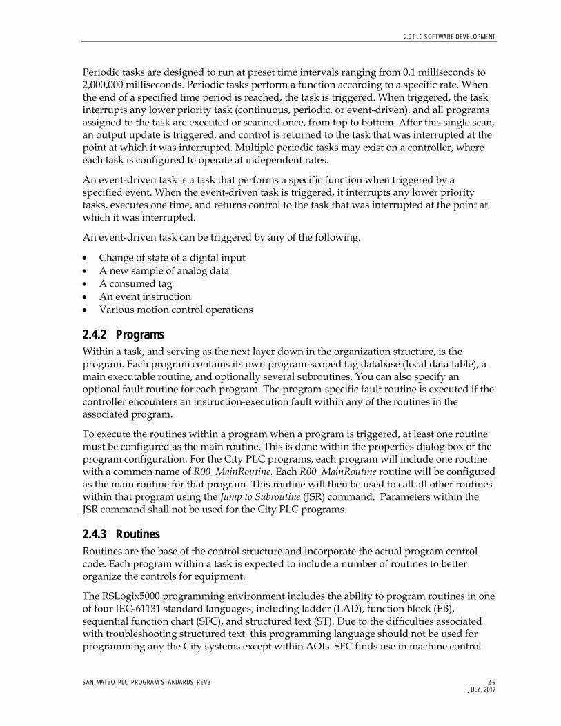
Periodic tasks are designed to run at preset time intervals ranging from 0.1 milliseconds to 2,000,000 milliseconds. Periodic tasks perform a function according to a specific rate. When the end of a specified time period is reached, the task is triggered. When triggered, the task interrupts any lower priority task (continuous, periodic, or event-driven), and all programs assigned to the task are executed or scanned once, from top to bottom. After this single scan, an output update is triggered, and control is returned to the task that was interrupted at the point at which it was interrupted. Multiple periodic tasks may exist on a controller, where each task is configured to operate at independent rates.
An event-driven task is a task that performs a specific function when triggered by a specified event. When the event-driven task is triggered, it interrupts any lower priority tasks, executes one time, and returns control to the task that was interrupted at the point at which it was interrupted.
An event-driven task can be triggered by any of the following.
• Change of state of a digital input • A new sample of analog data • A consumed tag • An event instruction • Various motion control operations
2.4.2 Programs Within a task, and serving as the next layer down in the organization structure, is the program. Each program contains its own program-scoped tag database (local data table), a main executable routine, and optionally several subroutines. You can also specify an optional fault routine for each program. The program-specific fault routine is executed if the controller encounters an instruction-execution fault within any of the routines in the associated program.
To execute the routines within a program when a program is triggered, at least one routine must be configured as the main routine. This is done within the properties dialog box of the program configuration. For the City PLC programs, each program will include one routine with a common name of R00_MainRoutine. Each R00_MainRoutine routine will be configured as the main routine for that program. This routine will then be used to call all other routines within that program using the Jump to Subroutine (JSR) command. Parameters within the JSR command shall not be used for the City PLC programs.
2.4.3 Routines Routines are the base of the control structure and incorporate the actual program control code. Each program within a task is expected to include a number of routines to better organize the controls for equipment.
The RSLogix5000 programming environment includes the ability to program routines in one of four IEC-61131 standard languages, including ladder (LAD), function block (FB), sequential function chart (SFC), and structured text (ST). Due to the difficulties associated with troubleshooting structured text, this programming language should not be used for programming any the City systems except within AOIs. SFC finds use in machine control

2.0 PLC SOFTWARE DEVELOPMENT
SAN_MATEO_PLC_PROGRAM_STANDARDS_REV3 2-10 JULY, 2017
where a defined repetitive sequence is required. Therefore, the applicability of SFC is limited for a process-intensive application.
The two main programming languages to be utilized for the City control programs will be ladder and function block. Due to the operations available, discrete (or Boolean) logic is best served through the use of ladder code. Function block on the other hand, allows for a large section of code to be viewed simultaneously, leading to easier troubleshooting. An FB, as applied by Rockwell Software, serves as a data tag and hence utilizes more CPU memory than functions used in the ladder programming environment. Therefore, line for line, a routine programmed in ladder will use less memory space in the CPU than a routine programmed in FB. As a result, it may be advantageous (though not mandatory) to configure routines using the ladder programming language.

SAN_MATEO_PLC_PROGRAM_STANDARDS_REV3 3-1 AUGUST 2016
3.0 Tagging/Naming Conventions
3.1 PLC Naming Conventions The City requires that new PLC programming be coded using Rockwell Automation’s RSLogix 5000 software (CPR9). In the RSLogix 5000 programming environment, ControlLogix projects are broken down into tasks, programs, and routines. These software components and other specific subcomponents of the software need to have names applied, which uniquely identify them.
3.1.1 PLC File and Controller Names The RSLogix 5000 PLC file names and the ControlLogix controller names should be representative of the controller’s primary control function as well as include a reference to the site name. The following syntax should be used.
_ffPLCnnn
ff Facility Number nnn Control Panel Number
Example: _97PLC100
Refer to Design Standard 05 – Equipment and Instrument Identification Standards document for a listing of the tag numbering components.
3.1.2 PLC Hardware Names (Communication and IO modules) Communication and IO modules added to a PLC configuration require unique names. The names assigned to communications and IO modules should provide an indication of module type, rack location, and slot location. These names should align themselves with information associated with facility loop databases. For communication and IO modules, the following syntax should be used.
RxxSyy_AA
AA Module Type (DI, DO, AI, AO, EN, CN, DN, MB, SR) where DI = Discrete Input
DO = Discrete Output AI = Analog Input AO = Analog Output EN = Ethernet Communications CN = ControlNet Communications DN = DeviceNet Communications MB = Modbus Communications SR = Serial Communications HC = High Speed Counter PI = Pulse Input

3.0 TAGGING/NAMING CONVENTIONS
SAN_MATEO_PLC_PROGRAM_STANDARDS_REV3 3-2 JULY, 2017
Rxx Rack Number (00 – xx) Syy Slot Number (00 – 16)
Example 1: R03S06_DI; Discrete input module in rack 03, slot 06 Example 2: R00S01_EN; Ethernet communications module in rack 00, slot 01
3.1.3 ControlLogix Task Names Within a ControlLogix PLC program, only one continuous task can be configured. However, multiple periodic or event driven tasks can be added. Task names should be such that the task priority, function of the task, and the rate at which a task is called (periodic tasks only) is shown. The following syntax is to be used for task names.
Taa_bbbbbbbbbb_XXms
Taa Task Number aa – Task number: The lower the task number the higher the priority in the range 01 to 15. Task 00 is reserved for the continuous task and represents lowest priority task.
bbbbbbbbbb Task Descriptive Name (25 characters max) XXms Reserved for periodic tasks. XX indicates the task time interval in
milliseconds.
3.1.4 ControlLogix Program File Names The PLC program should be divided into logical program groups such that all control code for a given unit process is contained within a separate program. For each program, the following syntax should be used.
Paa_bbbbbbbbbb
aa Program execution order in the task bbbbbbbbbb Program Descriptive Name (25 characters max)
3.1.5 ControlLogix Routine Names Routines should be given a name representative of the logic they execute. Every program will contain one main routine used to call all other subroutines in that program utilizing a series of JSR instruction. The main routine will simply be called R00_MainRoutine. The subroutine name should contain a prefix that will allow the routines to be put in order to show how they are called from the main program. The following syntax should be used.
Raa_bbbbbbbbbb
aa Routine order of sequence when jumped to from the R00_MainRoutine
bbbbbbbbbb Routine Descriptive Name (25 characters max)

3.0 TAGGING/NAMING CONVENTIONS
SAN_MATEO_PLC_PROGRAM_STANDARDS_REV3 3-3 JULY, 2017
3.2 PLC Software Tagging Criteria 3.2.1 Tagging Overview The tagging scheme is designed to be as simple as possible and still provide adequate capability to uniquely identify each control system loop.
3.2.2 Tag Numbering Format The software tag number will be a sequence of alpha and numeric components. The base tag should use a format of:
_ffISAlllnn
Where a data type includes subcomponents (elements), the tag will automatically include the necessary element information and follow a format of:
_ffISAlllnn.aaaaaaaa
ff Facility Number (F) ISA ISA or related symbol defining equipment type lll Loop Number (LN) nn Unit Number (UN) aaaaaaaa Data Type Element (TA)
Example: _01PIT23456.PV
Refer to Design Standard 05 – Equipment and Instrument Identification Standards document for a listing of the tag numbering components. Additional components will be added to the Design Standard 05 – Equipment and Instrument Identification Standards as needed during detailed design.

SAN_MATEO_PLC_PROGRAM_STANDARDS_REV3 4-1 AUGUST 2016
4.0 User-Defined Elements
4.1 General The A-B ControlLogix V27 CPU includes two forms of user-definable elements. These functions provide the ability for the programmer to create UDT and AOI. Using both types of user-definable elements enables the programmer to create more efficiently organized programs with increased standardization.
4.1.1 User Data Type The UDT is a custom data type (similar to an integer or real data type) that is created by the programmer. A UDT will usually incorporate a collection of tags of various data types into a single defined entity. An element in a UDT can be assigned any data type currently available in the CPU including that of another UDT. Once created, a UDT is available as a data type option available when creating database tags. Therefore, when a new tag is created in the tag database, the new tag can be assigned a UDT data type in the same way that it would be assigned an integer or real data type. The newly created tag of data type UDT will include all the elements of the UDT, which will show up as elements of the base tag (Base_Tag.element).
A consideration when creating a new UDT is that the processor uses memory based on the order used within the definition of the structure. The next 2 examples show two structures that have the exact same members, but the 1st example does not group data members of the same type consecutively and the second example does. Example #1 uses 32 bytes (256 bits or 16 words) of memory and Example #2 uses only 20 bytes (160 bits or 10 words). In other words, example #2 uses 60% less memory than example #1 just because it is grouped properly in the UDT. It is also important to note that the processor sets aside memory to optimize communication with SCADA. This means that there is actually a double impact if the UDTs are not set up properly.
The exception to grouping data structures according to data type occurs when you need to set up a UDT to match a particular system variable from the PLC status file. In these cases the UDT should be setup to match the data format presented in the user manuals. Member names for these UDTs should match the examples in order to allow the easiest troubleshooting.
Structure Name: EXAMPLE1
NAME Data Type Description
BOOL1 BOOL 1st BOOL
INT1 INT 1st INTEGER
BOOL2 BOOL 2nd BOOL

4.0 USER-DEFINED ELEMENTS
SAN_MATEO_PLC_PROGRAM_STANDARDS_REV3 4-2 JULY, 2017
NAME Data Type Description
INT2 INT 2nd INTEGER
BOOL3 BOOL 3rd BOOL
TIMER TIMER Internal Timer
BOOL4 BOOL 4th BOOL
INT3 INT 3rd INTEGER
BOOL5 BOOL 5th BOOL
Figure 4-1 Sample Non-optimized UDT Configuration
Structure Name: EXAMPLE2
NAME Data Type Description
TIMER TIMER Internal Timer
BOOL1 BOOL 1st BOOL
BOOL2 BOOL 2nd BOOL
BOOL3 BOOL 3rd BOOL
BOOL4 BOOL 4th BOOL
BOOL5 BOOL 5th BOOL
INT1 INT 1st INTEGER
INT2 INT 2nd INTEGER
INT3 INT 3rd INTEGER
Figure 4-2 Sample Optimized UDT Configuration
User-defined data types, or structures, will be set up based on the Add On Instruction (reference next section for details) that is to be used and will encompass all of the SCADA interface points required for the template. Each member of the structure is referenced using an extension name. The structure is then assigned as a data type for a PLC tag. The program then references each member in the following format "TAG.NAME." where TAG is the PLC tag, or address, and NAME is the element within the user-defined data structure.
For the City of San Mateo projects, UDTs are created to serve one of two main purposes. A UDT can be created to fill a specific task such as reading the date and time from the CPU. A UDT can also be designed to work with specific equipment such as motor starters or field devices.
Data created to work with specific equipment types may be split into two UDTs. One UDT designed to handle all PLC internal data. The other equipment-specific UDT designed to provide an interface to the HMI. Separating UDT data into internal data and HMI data

4.0 USER-DEFINED ELEMENTS
SAN_MATEO_PLC_PROGRAM_STANDARDS_REV3 4-3 JULY, 2017
simplifies the tasks associated with creating the HMI applications as well as preventing unnecessary data from being passed between a PLC and HMI. Where applicable, this approach is implemented.
UDTs designed for interfacing to SCADA/HMI systems will not include any additional identifier in the UDT name. UDTs designed for internal PLC use will include an additional “_DATA” identifier at the end of the UDT name
Table 4-1 lists HMI specific UDTs created for the City PLC programs. Additional UDTs will be added as the City projects evolve.
TABLE 4-1 Approved UDT
UDT Name UDT
Purpose Description and Functions A01 Analog Input Scaling and Alarming Analog input scaling, analog alarming, analog alarm
setpoint adjustment, test mode selection, alarm disable mode selection, and calibration mode selection
C01 PID Data Standard PID control algorithm data block including setpoint (SP), process variable (PV), control variable (CV), tuning parameters, auto/manual selection and control, and cascade mode control
C02 Compliance Data Standard process variable compliance data including interval time, high and low ranges, daily and monthly min/max, out of compliance time
C03 Totalization Data Standard totalization data including total today, total Monday, total Tuesday, total Wednesday, total Thursday, total Friday, total Saturday, total Sunday.
C04 Dosage Control Chemical Injection control data C05 Lead/Lag Control Data block used for standard Lead/Lag selection and
control. C06 Sequencer Control Data block used for standard Lead-Lag1-Lag2-Lag3-
Standby selection and control. D01 Discrete Alarm Discrete alarm data including alarm state and alarm
disable. M01 Fixed Speed Motor Data Block Standard motor data block (FVNR and FVR) including
on/off/fail status, A/M selection and indication, RTH, NOS, RTH reset, NOS reset, run direction, motor current, and thermal utilization
M02 ASD Data Block Standard ASD data block including on/off/fail status, A/M selection and indication, RTH, NOS, RTH reset, NOS reset, run direction, motor current, thermal utilization, and motor speed (percent)
V01 Two Position Valve Data Block Standard two position valve data block including open status, close status, transitioning status, fail alarm, and A/M selection and control
V02 Open-Stop-Close Valve Data Block Standard discrete control variable position valve data block including opening status, closing status, stopped status, full open status, full closed status, fail alarm, and A/M selection and control
V03 Modulating Valve Data Block Modulating valve data block including valve position indication (percent), fail alarm, and A/M selection and control
Notes: A/M auto/manual

4.0 USER-DEFINED ELEMENTS
SAN_MATEO_PLC_PROGRAM_STANDARDS_REV3 4-4 JULY, 2017
TABLE 4-1 Approved UDT
UDT Name UDT
Purpose Description and Functions CV control variable ft3/minute cubic feet per minute FVNR full-voltage nonreversing FVR full-voltage reversing g/sec grams per second mgd million gallons per day NOS number of starts (Cycles) PV process variable RTH run time hours SP setpoint ASD adjustable-speed drive
Figure 4-3 shows sample tag _97LIT00200. The tag is configured with a data type of A01 (analog input). As shown, the tag includes a number of elements which are a mix of real and Boolean data types. Every tag that is assigned a data type of A01 will include the same set of tag elements.
Figure 4-3 Sample Tag
4.2 Add-On Instructions The AOI is a custom-designed control element created by the programmer to incorporate PLC code designed for a specific task. The AOI is then applied, as a standard programming element, during PLC programming. AOIs are best applied to programming tasks requiring repetitive standardized code such as analog input scaling or analog alarm generation.
For the City PLC programs, an AOI can be created using ladder or FB. Once created, an AOI becomes a standard programming element accessed during PLC code creation in the same manner as other programming elements such as timers/counters or computational

4.0 USER-DEFINED ELEMENTS
SAN_MATEO_PLC_PROGRAM_STANDARDS_REV3 4-5 JULY, 2017
elements. As indicated in Figure 4-4, Access to Add-On Instructions, AOIs are accessed from the Add-On tab during programming.
Figure 4-4 Access to Add-On Instructions
The programmers shall use the Rockwell Automation generated AOIs for the City of San Mateo PLC programs. Additional AOIs will be added as the City’s projects evolve. For detailed description of a particular AOI, refer to the Rockwell Automation Guidelines.

SAN_MATEO_PLC_PROGRAM_STANDARDS_REV3 5-1 AUGUST 2016
5.0 PLC Program Documentation
All control programs created for the City need to include a minimum level of documentation integrated into the control code. This documentation is required to allow others, besides the original programmer, to understand the operation and functionality of the control code. This documentation is critical during the commissioning process and for future maintenance requirements.
Program documentation needs to describe individual control routines, to describe individual data tags, and to track changes to control code for maintenance purposes.
5.1 Routine Documentation Sufficient documentation within each routine should be included to adequately describe the functionality for each section of code, how the section of code works, and what variables affect the logic.
For a routine programmed using ladder, the first rung in the ladder file should use the No operation Command (NOP) instruction with a description of the purpose of the routine. Additional NOP rungs should be added, where appropriate, to separate the ladder routine into logical blocks, with each NOP rung providing a description of the purpose of the given section of code. Finally, individual rungs of PLC code should be documented, where required, to clarify complex code such as lengthy calculations, jump routines, or index-addressed code.
Figure 5-1 shows a sample ladder routine with typical documentation.
Figure 5-1 Sample Ladder Routine
For routines programmed in the FB language, the text box will serve the same purpose as the documented NOP rung in ladder routines. For an FB routine, one text box should provide a description of the routines purpose. Additional text boxes should then be added, where appropriate, to clarify sections of code.
5.0 PLC PROGRAM DOCUMENTATION
SAN_MATEO_PLC_PROGRAM_STANDARDS_REV3 5-2 JULY, 2017
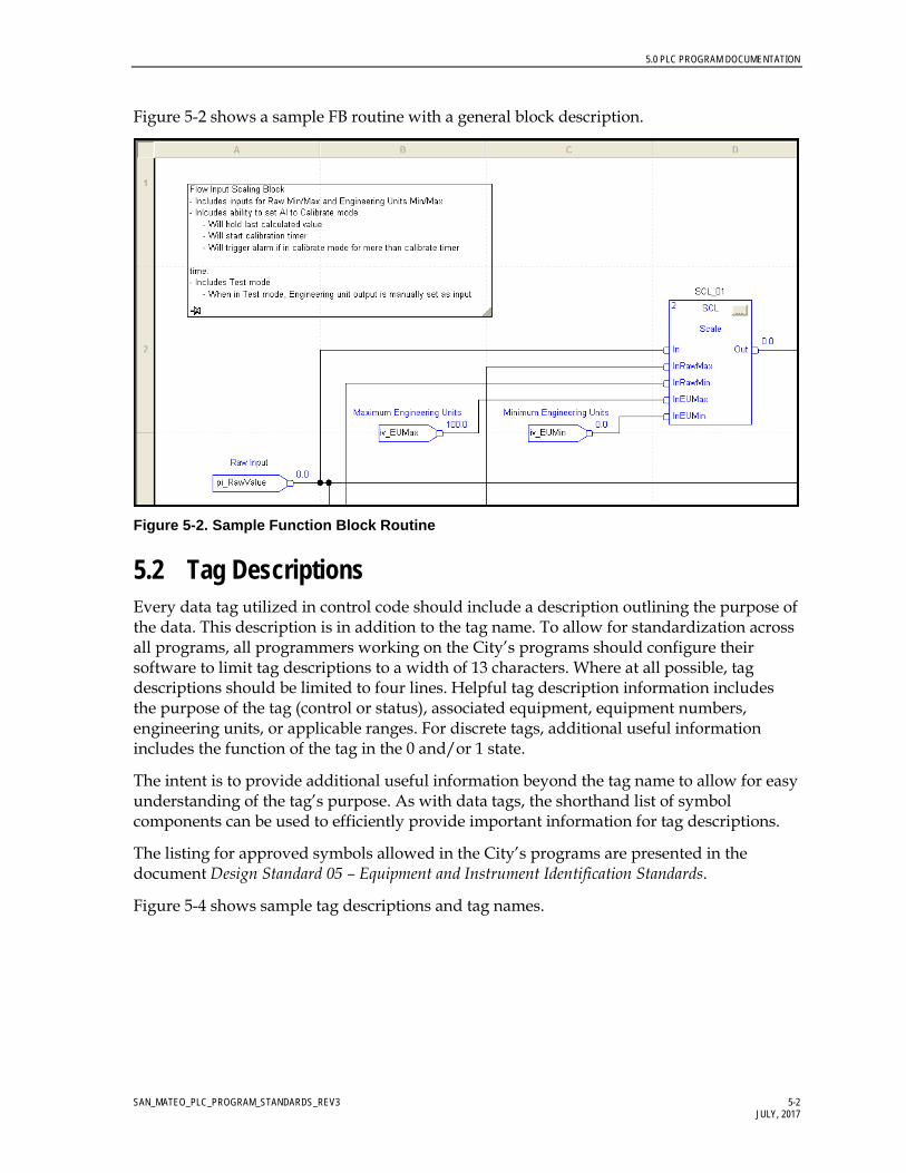
Figure 5-2 shows a sample FB routine with a general block description.
Figure 5-2. Sample Function Block Routine
5.2 Tag Descriptions Every data tag utilized in control code should include a description outlining the purpose of the data. This description is in addition to the tag name. To allow for standardization across all programs, all programmers working on the City’s programs should configure their software to limit tag descriptions to a width of 13 characters. Where at all possible, tag descriptions should be limited to four lines. Helpful tag description information includes the purpose of the tag (control or status), associated equipment, equipment numbers, engineering units, or applicable ranges. For discrete tags, additional useful information includes the function of the tag in the 0 and/or 1 state.
The intent is to provide additional useful information beyond the tag name to allow for easy understanding of the tag’s purpose. As with data tags, the shorthand list of symbol components can be used to efficiently provide important information for tag descriptions.
The listing for approved symbols allowed in the City’s programs are presented in the document Design Standard 05 – Equipment and Instrument Identification Standards.
Figure 5-4 shows sample tag descriptions and tag names.

5.0 PLC PROGRAM DOCUMENTATION
SAN_MATEO_PLC_PROGRAM_STANDARDS_REV3 5-3 JULY, 2017
Figure 5-4 Sample Tag Descriptions and Tag Names

SAN_MATEO_PLC_PROGRAM_STANDARDS_REV3 6-1 AUGUST 2016
6.0 PLC Program Development
One key objective for PLC program development is to provide a program structure that is easy for O&M staff to understand and troubleshoot. A PLC program is built once and then adapted to changing operational needs for years. Defining PLC programming standards will make the PLC programs easier to understand and will reduce operating costs for the City of San Mateo, allowing for a more sustainable system.
Creation of a new control program requires a basic understanding of the control system requirements and selected hardware. The ControlLogix CPU part number and firmware version should be known at the outset of program creation. With this information and a preliminary IO layout, a new control program can be started.
Once a new program has been started, the steps required to program a fully functioning control program include:
• Create add-on elements (UDT and AOIs) − Import from standards files
• Add IO configuration (IO racks, IO modules, etc.) • Create preliminary tag database for field devices • Configure basic program structure (tasks and programs) • Add standard routines (Overhead, System Monitoring, etc.)
− Import from standards files • Add recurring code using UDTs and AOIs
− Analog Scaling − Analog Alarms
• Add detail control code • Add initialization, fault handling, and power-up routines
All RSLogix5000-based programs will be configured based on the common standards listed below. A standard template/example PLC program file shall be provided by the City of San Mateo, containing all necessary elements, including but not limited to the following: AOI’s, UDT’s, program structure and standard logic used in all PLCs.
6.1 General This section lists standards to be implemented in the creation or modification of any the City’s facility PLC programs. • All control code that is to be continuously scanned through the main continuous task
(T00_Main_Task) will be separated into logical programs within the main task. − Programs will be based on unit processes

6.0 PLC PROGRAM DEVELOPMENT
SAN_MATEO_PLC_PROGRAM_STANDARDS_REV3 6-2 JULY, 2017
• Each program within a task will include one main routine that will be used to call all other routines within a program. − No control code other than routine calls (JSR) will be included in a main routine. − All main routines will be named R00_MainRoutine
• Routines can be programmed in IEC 61131 compliant ladder, FB, or SFC. − Structured text will not be allowed unless specific approval is granted by the City of
San Mateo. − Function Block routines will use a D sheet size (22 by 34 inches) set to landscape
mode. • An overhead routine (to be included in the overhead program within the main task) is to
be included. This routine is used to provide standard code not affiliated with any specific process area and which may be used throughout the remainder of the PLC program. Such code may include (but is not limited to): − continuous timers for general program use − PID control timer(s) − Provide a daily roll over bit
o Roll over time used to trigger the roll over bit must be adjustable while the CPU is in run mode without the need to perform online edits.
• All programs will include an initialization routine. − This routine is separate from any power-up or fault handling routines. − This routine will be used to set hard-coded and default setpoints as well as to
initialize or reset sequence controls. − Activation of initialization routines will be from manually toggled bits. No
automatic initialization should be included to prevent accidental overwriting of existing configurations.
− All initialization routines will be named R99_Initialize • A control system monitoring routine is to be included in the overhead project. This
routine will include PLC code which will: − Read the time and date from the CPU − Retrieve the CPU run/remote/program status − Retrieve the CPU key switch position − Retrieve the maximum and last scan times − Retrieve the major and minor fault bits − Retrieve the fault status from applicable IO cards controlled by the CPU
• All PLC to PLC communications will be configured using Produced/Consumed tag arrays.
6.2 Tags and Data This section lists standards to be implemented in the creation or modification of tags or data for any the City’s PLC programs.

6.0 PLC PROGRAM DEVELOPMENT
SAN_MATEO_PLC_PROGRAM_STANDARDS_REV3 6-3 JULY, 2017
• Tag descriptions will be included for all data tags used in PLC control code.
− The control program tags and descriptions will be configured per Sections 4 and 5 of this document as well as the Design Standard 05 (Equipment and Instrumentation Guide).
• Separate tags will be configured for status and control functions to/from all HMI units.
− Where possible, UDTs dedicated to HMI data should be used.
• Boolean data type is not allowed for base tags.
− A minimum of one double-integer array should be created to allow for the use of Boolean tags in the PLC program.
− Actual tags used in the control program will be aliased to bits within the double integer array as required.
• Integer data types are not allowed for base tags
− A minimum of one integer array should be created to allow for the use of Integer tags in the PLC program.
− Array size will be in multiples of 2 registers (for example, array size 2, 4, 6, 8).
− Actual integer tags used in the control program will be aliased to the integer array as required.
• Single-integer data types are not allowed for base tags.
− Where necessary, one single-integer array will be created to allow for the use of integer tags in the PLC program.
− Array size will be in multiples of 4 registers (for example, array size 4, 8, 12, 16).
− Actual single-integer tags used in the control program will be aliased to the single-integer array, as required.
• Indexed addressing is not allowed for equipment control.
− Indexed addressing may be utilized for noncritical functions such as data transfer to/from the HMI if approved by the City of San Mateo.
− In cases where indexed addressing is used, sufficient documentation must be included in the program to clearly describe the functioning of the code and all addressing associated with the code.
• UDTs are allowed.
− A library of approved UDTs will be provided as part of the City’s standard sample PLC program.
− Additional UDTs can be used if approved by the City prior to implementation.

6.0 PLC PROGRAM DEVELOPMENT
SAN_MATEO_PLC_PROGRAM_STANDARDS_REV3 6-4 JULY, 2017
• AOIs not specifically noted elsewhere in this document or detailed in the City AOI Detail documents (Appendix A), are allowed if approved by the City prior to implementation.
− Any AOI created outside of the City control must allow access to the source code. Locking or password protecting of AOIs is not allowed.
6.2.1 Analog Input Data • Scaling of analog inputs to engineering units will be done using PLC code based on a
standard AOI. Aside from the scaling routine, all PLC logic shall use the scaled engineering unit values. o Scaling of analog inputs to engineering units will not be done in the IO cards. o High-High, High, Low, and Low-Low analog alarms will be provided for each
analog input using a standard AOI. • Create one routine for each analog input module to provide scaling for each channel
within an analog input module. • For each analog input, alias the instrument tag to the appropriate analog input module
element. o Example: For level transmitter 03LIT00200 physically terminated in Rack 01, Slot 02,
Channel 00, Figure 6-3 shows analog tag _03LIT00200_Level aliased to the first input (channel 00) of the analog input card.
Figure 6-3. Analog Tag Aliased to Analog Input Card
6.2.2 Messaging Data between PLCs • Data required from a different PLC shall be obtained by doing data reads. Data writes
are not to be used at any time. • To reduce system overhead and reduce network traffic, all data shall be packed into
arrays by the originating PLC, prior to being read. The READING PLC will be brake out the data array into individual elements for use by the program.
• Data shall be separated into REAL and INTEGER data arrays within the originating PLC and receiving PLC. Real data will use the Real data array with a length of 10 elements. INTEGER and BOOL data types will us the INTEGER array with a length of 20 elements.
• The data array names within a given PLC shall be based upon the name of the PLC and the data type.
o Example: Real data stored in _03PLC100 to be read by other PLCs: REAL array in _03PLC100 will be: _03PLC100_Real. REAL array in _04PLC100 will be: _04PLC100_Real.

6.0 PLC PROGRAM DEVELOPMENT
SAN_MATEO_PLC_PROGRAM_STANDARDS_REV3 6-5 JULY, 2017
• For BOOL data types, individual tags are mapped to bits within an INT word, which is part of the integer data array. This reduces the number of words required for communications. Within the integer data array a variable number of integers, located at the end of the array, will be dedicated to BOOL data. It is desirable to limit BOOL data as much as possible to limit unused bits in the system.
o Example: Transfer of BOOL elements from _03PLC100 _03PM00101.Remote – Pump 1 Local Remote Hand Switch _03PMP00101.Failed – Pump 1 Fault Status _03PMP00101.Running – Pump 1 running status _03PMP00102.Remote – Pump 2 Local Remote Hand Switch _03PMP00102.Failed – Pump 2 Fault Status _03PMP00102.Running – Pump 2 running status
o The BOOLs in _03PLC100 can be mapped into INT elements as follows: _03PM00101.Remote – _03PLC100_Int[0].0 _03PMP00101.Failed – _03PLC100_Int[0].1 _03PMP00101.Running – _03PLC100_Int[0].2 _03PM00102.Remote – _03PLC100 PLC_Int[1].0 _03PMP00102.Failed – _03PLC100 PLC_Int[1].1 _03PMP00102.Running – _03PLC100_PLC_Int[1].2
Refer to Appendix D for a listing of all Message Data mappings.
6.2.3 Standard Program Structure All ControlLogix programs shall be based on the tasks, programs, and routines structure indicated below.
• Main Task (continuous – T00_Main_Task) o Overhead Program (P01_Overhead) Main Routine (R00_MainRoutine) Overhead Routine (R01_Overhead) Control System Monitoring Routine (R02_System_Stat) I/O module Status Monitoring Routine (R03_IO_Card_Monitoring) DeviceNet Network Monitoring Routine (R03_DNET_Stat)
o Input Data Map Program (P02_Input_Scaling) Main Routine (R00_MainRoutine) Analog Scaling Routine 1 (R10_AI_Card1) Analog Scaling Routine 2 (R11_AI_Card2) Analog Scaling Routine 3 (R12_AI_Card3)
o Unit Process 1 Code Program (P10_UnitAreaName) Main Routine (R00_MainRoutine) Routine 1 Sub-process 1 controls (R01_SubProcessName) Routine 2 Sub-process 2 controls (R02_SubProcessName)

6.0 PLC PROGRAM DEVELOPMENT
SAN_MATEO_PLC_PROGRAM_STANDARDS_REV3 6-6 JULY, 2017
Routine 3 Sub-process 3 controls (R03_SubProcessName) Program Initialization Routine (R99_Initialize)
o Unit Process 2 Code Program (P11_UnitAreaName) Main Routine (R00_MainRoutine) Routine 1 Sub-process 1 controls (R01_SubProcessName) Routine 2 Sub-process 2 controls (R02_SubProcessName) Routine 3 Sub-process 3 controls (R03_SubProcessName)
o Communications Program (P91_Communications) Main Routine (R00_MainRoutine) Communications 1 Routine (PLC_x/PLC_a messages) (R01_PLCa) Communications 2 Routine (PLC_x/PLC_b messages) (R02_PLCb) Communications 3 Routine (Other communications such as Modbus or Serial
if required) o Initialization Program (P99_System_Initialize) Main Routine (R00_MainRoutine)
• Periodic Task 1 (T01_Cmplnce_5000ms) o Compliance (P02_Cmplnce) Main Routine (R00_MainRoutine) Compliance control code (R01_Compliance)
o PIDs (P10_UnitAreaName) Main Routine (R00_MainRoutine) Compliance control code (R01_process_PID)
• Periodic Task 2 (Txx_description_xxMS; where applicable) • Event Task 1 (Txx_description; where applicable) • Event Task 2 (Txx_description; where applicable) • Etc. • Unscheduled Programs/Phases
o Revision Control Program Revision Document 1 Revision Document 2
o Temporary Ladder Routine For Code Development o Temporary Function Block Routine For Code Development

SAN_MATEO_PLC_PROGRAM_STANDARDS_REV3 7-1 AUGUST 2016
7.0 PLC Programming Best Practices
When creating a PLC program, there are numerous paths to the same result. There is no right or wrong way to program a PLC. Only what works and what does not. As such, some specific practices result in a better developed PLC program, with “better” being a relative term and having numerous shades of grey. This section sets out to document various “Best Practices” which should be used when developing PLC programs for the City of San Mateo.
7.1 Simplify Rungs of Code For ladder routines, avoid long complicated rungs of code (Figure 7-1).
• Break up a complicated rung of code into smaller parts. • Avoid excessive branching in a single rung of code. • Use a single rung comment at the beginning of the group to explain what you are doing
(Figure 7-2).
Avoid this… Figure 7-1 Complicated Rungs of Ladder Code

7.0 PLC PROGRAMMING BEST PRACTICES
SAN_MATEO_PLC_PROGRAM_STANDARDS_REV3 7-2 July 2016
Try using this instead… Figure 7-2 Simplified Rungs of Ladder Code
7.2 Data Types Use a data type appropriate for the information being manipulated.
• The RSLogix5000 software is configured to select a default data type (usually DINT). • Maintain consistency throughout the PLC program for given functions keeping in mind:
− DINT Range: -2147483648 to 2147483647 − INT Range: -32768 to 32767 − SINT Range: -127 to 128
7.3 Prefacing Conditions When prefacing an output with test or condition, apply a test or condition to each line.
• Do not rely on a default condition on the first branch with conditional test on the second branch.

7.0 PLC PROGRAMMING BEST PRACTICES
SAN_MATEO_PLC_PROGRAM_STANDARDS_REV3 7-3 July 2016
• Apply conditional test to each branch
• In Figure 7-3 below, Rung 26 is not the preferred method, Rung 27 is the preferred method
Figure 7-3 Prefacing Conditions in Ladder
7.4 Discrete Controls Discrete controls include the functions OTE (output Energize), OTL (output Latch), OTU (Output Unlatch). Where possible, utilize the OTE function for discrete control. The OTL and OTU pairs should not be overused where the OTE can provide the same functionality.
7.5 Equations Long, complicated equations (such as in chemical dosing) should be split into smaller calculations where feasible. The compute block (CPT) is useful, but equations can get a bit long and hard to follow. Splitting calculations into smaller parts with subtotals allows for easier verification of calculations during commissioning.
ADD, SUB, MUL, DIV use less memory than CPT; therefore, with easy, simple calculations avoid using the CPT block.
7.6 Timers • Timer setpoints from HMI should be in required units (hour, minutes, seconds).
• If seconds only then PLC should be configured to convert seconds to milliseconds (ms) for input to timer setpoint (MUL to convert seconds to ms).
• If setpoint requires minutes and seconds, use separate tags for minutes and seconds (including separate tags for setpoint feedback). Combine times in PLC code if applicable using appropriate logic.

7.0 PLC PROGRAMMING BEST PRACTICES
SAN_MATEO_PLC_PROGRAM_STANDARDS_REV3 7-4 July 2016
o For example, if hours and minutes are required for the setpoint inputs, the programmer can convert hours to minutes then add the minutes setpoint to provide total time setpoint.
• Where called for, include countdown logic to provide an indication of the time remaining to the activation of specified function.
− Time remaining should utilize same format as time setpoint including separate tags for hours or minutes as required.
7.7 Counters Counters can be done in different ways. One option is to use a counter block (CTU or CTD) (Figure 7-5). Another is to use an ADD block (Figure 7-6).
• CTU/CTD provides additional status information. • ADD uses less memory. • No preferred method. Just be consistent within a section of code (routine or program).
Figure 7-5 Counter Using CTU

7.0 PLC PROGRAMMING BEST PRACTICES
SAN_MATEO_PLC_PROGRAM_STANDARDS_REV3 7-5 July 2016
Figure 7-6 Counter Using ADD
7.8 Button Control A two-state toggle control method using single command bit with feedback, shown in Figure 7-7.
• Can be used for auto/manual selection and feedback • Is not applicable to PanelView Plus, as buttons do not include a set value function • Provides for positive control confirmation:
− If control from SCADA configured to use momentary command, it is possible for the PLC to miss the command. This logic eliminates this possibility.
• Requires button action on SCADA using Set Tag to 1 type action • Separates status feedback for use in PLC code and for status display on SCADA.
Figure 7-7 Two-State Toggle Control

7.0 PLC PROGRAMMING BEST PRACTICES
SAN_MATEO_PLC_PROGRAM_STANDARDS_REV3 7-6 July 2016
7.9 Sequence Control Sequence control is any group of control actions in which the result of one action (step) initiates an adjacent action (step + 1), normally applied to sequences of more than two steps.
• Sequence Indication and Control
− For every sequence-controlled operation, the PLC should be configured to include a sequence reset button in case a sequence hangs up.
− For every sequence controller, PLC should include a sequence fail alarm indication.
− For every sequence controller, PLC should include a sequence step indication. o Step indication of data type SINT or INT o Do not use data type real for sequence step indication
7.10 PID Control • PIDs configured to use independent tuning parameters
• PIDs are not to be programmed within process control routines under the main continuous task and but rather as separate periodic tasks
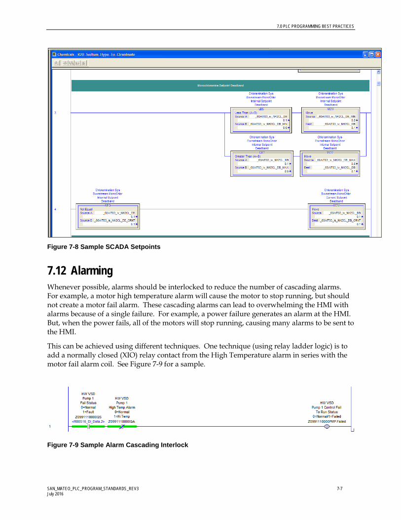
7.11 SCADA Set points PLC should be configured to verify that set point is within allowable range (see sample code in Figure 7-8).
• If set point is greater than maximum allowable, move max to set point • If set point is less than minimum allowable, move min to set point • Finally, move se tpoint to required location
Use a separate feedback tag for set point inputs. Indicate on HMI.
7.0 PLC PROGRAMMING BEST PRACTICES
SAN_MATEO_PLC_PROGRAM_STANDARDS_REV3 7-7 July 2016
Figure 7-8 Sample SCADA Setpoints
7.12 Alarming Whenever possible, alarms should be interlocked to reduce the number of cascading alarms. For example, a motor high temperature alarm will cause the motor to stop running, but should not create a motor fail alarm. These cascading alarms can lead to overwhelming the HMI with alarms because of a single failure. For example, a power failure generates an alarm at the HMI. But, when the power fails, all of the motors will stop running, causing many alarms to be sent to the HMI.
This can be achieved using different techniques. One technique (using relay ladder logic) is to add a normally closed (XIO) relay contact from the High Temperature alarm in series with the motor fail alarm coil. See Figure 7-9 for a sample.
Figure 7-9 Sample Alarm Cascading Interlock

SAN_MATEO_PLC_PROGRAM_STANDARDS_REV3 8-1 July 2016
8.0 Glossary
AOI Add-On Instruction – Reusable PLC programming instruction, created by the programmer, to provide specific control functions or features
Back Plane Interfaced used to pass data into and out of modules. The backplane can be physical (ControlLogix IO rack) or virtual (CompactLogix, which does not include a separate IO rack)
Base Rack IO rack containing a PLC. May or may not include IO modules
CPR Coordinated Product Release – Term used by Rockwell Software to define a suite of software and hardware firmware levels tested by Rockwell Software and certified to work together. For the City control system projects all software used and hardware firmware will be CPR9 compliant.
CTD down counter
CTU up counter
Event Instruction The EVENT instruction is used to trigger one execution of an event task.
Event Task A task that performs a specific function when triggered by a specified event. When the event task is triggered, it interrupts any lower priority tasks, executes one time, and returns control to the task that was interrupted, at the point at which it was interrupted.
human-machine interface
An open architecture operator interface that is configured using object technology
Input/Output External signals interfaced to the PLC control system. Can be hard wired or networked from physical devices (transmitters, motors, etc) or software applications (HMI, Historian Data Collector, Etc)
IO Module Input or Output module, installed within an IO Rack, used to provide a hardwired interface to field devices such as transmitters or motors
IO Rack For modular-based PLC control system, the IO Rack is the base structure used to house the various modules making up the PLC control system

8.0 GLOSSARY
SAN_MATEO_PLC_PROGRAM_STANDARDS_REV3 8-2 July 2016
programmable logic controller
A modular microprocessor-based hardware device designed to monitor field device control signals, evaluate programmed logic based on field device signals, and provide appropriate output signals to control equipment for facility operation.
Remote IO IO modules contained within a remote rack
Remote Rack IO rack not containing a PLC, but which interfaces to a PLC via a network connection
UDT User Data Type created by the programmer containing single or multiple data elements of various types.

SAN_MATEO_PLC_PROGRAM_STANDARDS_REV3 8-1 July 2016

SAN_MATEO_PLC_PROGRAM_STANDARDS_REV3 8-1 July 2016

SAN_MATEO_PLC_PROGRAM_STANDARDS_REV3 July, 2016

City of San Mateo Clean Water Program Control System SCADA Programming
Standards
Revision 2
Prepared for
City of San Mateo
AUGUST, 2016
Prepared by CH2M

SAN_MATEO_HMI_PROGRAM_STANDARDS_REV2.DOCX ii AUGUST, 2016
Contents
Section Page
Acronyms and Abbreviations ......................................................................................................... vi
1.0 Introduction ......................................................................................................................... 1-1 1.1 Purpose .................................................................................................................... 1-1
1.1.1 Target Audience ........................................................................................ 1-1 1.2 Overview ................................................................................................................. 1-1
1.2.1 Primary Objectives .................................................................................... 1-1 1.2.2 Scope ........................................................................................................... 1-2
1.3 Overall Philosophy ................................................................................................. 1-2 1.4 HMI Design Delivery ............................................................................................. 1-4
1.4.1 Approach .................................................................................................... 1-4 1.4.2 HMI Delivery Methodology .................................................................... 1-4
1.4.2.1 HMI Application Source Information .................................. 1-4 1.4.2.2 HMI Application Pre-Design ................................................. 1-4 1.4.2.3 HMI Standard Graphic Object Library ................................ 1-5 1.4.2.4 HMI Graphics Development ................................................. 1-5 1.4.2.5 HMI Database Development ................................................. 1-5 1.4.2.6 Operational Information Development ............................... 1-5 1.4.2.7 Historian Reporting ................................................................ 1-6 1.4.2.8 HMI Application Testing and Commissioning .................. 1-6
2.0 General Requirements ....................................................................................................... 2-1 2.1 System Architecture ............................................................................................... 2-1
2.1.1 General ........................................................................................................ 2-1 2.2 Software and Guidelines ....................................................................................... 2-2
2.2.1 HMI Software Requirements ................................................................... 2-2
3.0 HMI Graphics Layout and Navigation ........................................................................... 3-1 3.1 Graphics Components ........................................................................................... 3-1
3.1.1 Top Banner ................................................................................................. 3-2 3.1.2 Alarm Banner ............................................................................................. 3-2 3.1.3 Navigation Bar ........................................................................................... 3-2
3.2 Main Process Area .................................................................................................. 3-3 3.2.1 Level 1 ......................................................................................................... 3-3 3.2.2 Level 2 ......................................................................................................... 3-4 3.2.3 Level 3 ......................................................................................................... 3-5 3.2.4 Level 4 ......................................................................................................... 3-5
4.0 Color and Graphic Standards ........................................................................................... 4-1 4.1 General ..................................................................................................................... 4-1 4.2 Selection Buttons .................................................................................................... 4-1 4.3 Numeric Data .......................................................................................................... 4-2

CONTENTS
SAN_MATEO_HMI_PROGRAM_STANDARDS_REV2.DOCX iii AUGUST 2016
4.4 Object Information and Colors ............................................................................. 4-3 4.4.1 Valves and Gate Status ............................................................................. 4-4 4.4.2 Motor, Pump, and Fan Status .................................................................. 4-5 4.4.3 Instruments ................................................................................................ 4-5
5.0 Indication and Control Standards ................................................................................... 5-1 5.1 Overview ................................................................................................................. 5-1 5.2 Indication Standards .............................................................................................. 5-1
5.2.1 Analog Field Device .................................................................................. 5-1 5.3 Levels of Control .................................................................................................... 5-3
5.3.1 Equipment Control .................................................................................... 5-3 5.3.2 System Control......................................................................................... 5-12
6.0 Additional Display Information ..................................................................................... 6-1 6.1 Trend Display Organization ................................................................................. 6-1 6.2 Control System Monitoring .................................................................................. 6-1
7.0 Alarm Management ........................................................................................................... 7-1 7.1 Alarm Priorities ...................................................................................................... 7-2
7.1.1 Critical Alarms (Level 1)........................................................................... 7-2 7.1.2 Urgent Alarms (Level 2) ........................................................................... 7-3 7.1.3 High Alarm (Level 3) ................................................................................ 7-3 7.1.4 Alarm (Level 4) .......................................................................................... 7-3 7.1.5 Out Of Service ............................................................................................ 7-4
8.0 Glossary ................................................................................................................................ 8-1

CONTENTS
SAN_MATEO_HMI_PROGRAM_STANDARDS_REV2.DOCX iv AUGUST 2016
Tables
TABLE 4-1 Standard Color Conventions ...................................................................................... 4-1 TABLE 7-1 Sample Alarming Criteria and Priorities .................................................................. 7-2
Figures
Figure 1-1 HMI Lifecycle from ISA Standard 101.01 ................................................................... 1-3 Figure 2-1 City of San Mateo Existing WWTP System Architecture ......................................... 2-1 Figure 3-1 Layout on a standard HMI Monitor ........................................................................... 3-1 Figure 3-2 Sample Top Banner ....................................................................................................... 3-2 Figure 3-3 Sample Alarm Banner ................................................................................................... 3-2 Figure 3-4 Sample Navigation Tree ............................................................................................... 3-3 Figure 3-5: Sample Navigation from Displays ............................................................................. 3-4 Figure 4-1: Standard Display for Analog values .......................................................................... 4-2 Figure 4-2: Standard Display for Numeric Entry ......................................................................... 4-3 Figure 4-3: Standard Symbols for Valves and Gates ................................................................... 4-4 Figure 4-4: Standard Symbols for Pumps and Motors ................................................................ 4-5 Figure 4-5: Standard Symbols for Instruments............................................................................. 4-6 Figure 5-1 Standard Analog Pop-Up (Operations Tab) .............................................................. 5-1 Figure 5-2 Standard Analog Pop-Up (Alarms Tab) ..................................................................... 5-2 Figure 5-3 Standard Analog Pop-Up (Trend Tab) ....................................................................... 5-2 Figure 5-4 Standard Analog Pop-Up (Maintenance Tab) ........................................................... 5-3 Figure 5-5 Standard Modulating Valve Pop-Up (Operations Tab) ........................................... 5-4 Figure 5-6 Standard Modulating Valve Pop-Up (Alarms Tab) .................................................. 5-4 Figure 5-7 Standard Modulating Valve Pop-Up (Trend Tab) .................................................... 5-5 Figure 5-8 Standard Modulating Valve Pop-Up (Maintenance Tab) ........................................ 5-5 Figure 5-9 Standard Open-Close Valve Pop-Up (Operations Tab) ........................................... 5-6 Figure 5-10 Standard Open-Close Valve Pop-Up (Alarms Tab) ................................................ 5-6 Figure 5-11 Standard Open-Close Valve Pop-Up (Trend Tab) .................................................. 5-7 Figure 5-12 Standard Open-Close Valve Pop-Up (Maintenance Tab) ...................................... 5-7 Figure 5-13 Standard Constant Speed Pump Pop-Up (Operations Tab) .................................. 5-8 Figure 5-14 Standard Constant Speed Pump Pop-Up (Alarms Tab) ........................................ 5-8 Figure 5-15 Standard Constant Speed Pump Pop-Up (Trend Tab) ........................................... 5-9 Figure 5-16 Standard Constant Speed Pump Pop-Up (Maintenance Tab) ............................... 5-9 Figure 5-17 Standard Adjustable Speed Pump Pop-Up (Operations Tab) ............................. 5-10 Figure 5-18 Standard Adjustable Speed Pump Pop-Up (Alarms Tab) ................................... 5-10 Figure 5-19 Standard Adjustable Speed Pump Pop-Up (Trend Tab) ...................................... 5-11 Figure 5-20 Standard Adjustable Speed Pump Pop-Up (Maintenance Tab) .......................... 5-11 Figure 5-21 Lead / Lag Selection Pop-Up (Operations Tab) .................................................... 5-12 Figure 5-22 Lead / Lag Selection Pop-Up (Trend Tab) ............................................................. 5-13 Figure 5-23 Lead / Lag Selection Pop-Up (Maintenance Tab) ................................................. 5-13 Figure 5-24 PID Pop-Up (Operations Tab) .................................................................................. 5-14 Figure 5-25 PID Pop-Up (Maintenance Tab) .............................................................................. 5-14 Figure 5-26 PID Pop-Up (Trend Tab) ........................................................................................... 5-15 Figure 5-27 PID Pop-Up (Operations Tab) .................................................................................. 5-15 Figure 5-28 Dosage Pump Pop-Up (Trend Tab) ......................................................................... 5-16 Figure 6-1 Control System Overview Display Example ............................................................. 6-2

CONTENTS
SAN_MATEO_HMI_PROGRAM_STANDARDS_REV2.DOCX v AUGUST 2016
Figure 6-2 Example of a Control System Display for each component .................................... 6-3 Figure 7-1 Alarm Management Lifecycle ...................................................................................... 7-1 Figure 7-2 Symbol for Level 1 Alarms ........................................................................................... 7-3 Figure 7-3 Symbol for Level 2 Alarms ........................................................................................... 7-3 Figure 7-4 Symbol for Level 3 Alarms ........................................................................................... 7-3 Figure 7-5 Symbol for Level 4 Alarms ........................................................................................... 7-4

SAN_MATEO_HMI_PROGRAM_STANDARDS_REV2.DOCX vi AUGUST, 2016
Acronyms and Abbreviations
A/M auto/manual
A-B Allen-Bradley
AI analog input
AO analog output
AOI Add-On Instruction
ASD Adjustable Speed Drive
BOOL Boolean
cfm cubic feet per minute
CPR Coordinated Product Release
CPT compute block
CV control variable
DI discrete input
DINT double integer – 32 bits
DO discrete output
FB function block
ft3/minute cubic feet per minute
FSAT Factory Software Acceptance Test
FVNR full-voltage non-reversing
FVR full-voltage reversing
gph gallons per hour
gpm gallons per minute
GUI graphical user interface
HMI human-machine interface
I/O Input / Output
INT integer – 16 bits
IO Input / Output
JSR jump to subroutine command
LAD ladder
LAN Local Area Network

ACRONYMS AND ABBREVIATIONS
SAN_MATEO_HMI_PROGRAM_STANDARDS_REV2.DOCX vii AUGUST 2016
LCS Local control station in the field
LGO Library graphical object
mgd million gallons per day
MSG message commands
NOP No Operation Command
NOS number of starts
O&M Operations and Maintenance
ODVA Open DeviceNet Vendors Association
P&ID Process and Instrumentation Diagram
PCN Process Control Narrative
PCS Process Control System
PID Proportional Integral Derivative
PLC Programmable Logic Controller
PV Process variable
RIO Remote Input / Output
RTH run time hours
SCADA Supervisory Control And Data Acquisition
SFC sequential function chart
SINT single integer – 8 bits
SP Set point
ST structured text
TBD to be determined
UDT User Data Type
WAN Wide Area Network

SAN_MATEO_HMI_PROGRAM_STANDARDS_REV2.DOCX 1-1 AUGUST 2016
1.0 Introduction
1.1 Purpose
The purpose of this document is to establish the City of San Mateo (City) enterprise wide Human Machine Interface (HMI) application standards as applied to plant control systems utilizing Schneider Electric’s Wonderware System Platform software.
1.1.1 Target Audience
It is expected that users of this document will have a general knowledge of industrial control systems and a working knowledge of the Schneider Electric’s Wonderware System Platform software. In addition, users should have a working knowledge of Ethernet IP and communications between an HMI application and PLC controllers.
For further reference and additional information, please refer to the following documents.
City of San Mateo Clean Water Program Control System PLC Programming Standards
International Society of Automation (ISA) / American National Standard 101.01-2015: Human Machine Interfaces for Process Automation Systems
International Society of Automation (ISA) / American National Standard 18.2-2009: Management of Alarm Systems for the Process Systems
City of San Mateo Clean Water Program Design Standard 05 – Equipment and Instrument Identification Standards
1.2 Overview
1.2.1 Primary Objectives
The purpose of this design guide is to establish conventions, standards and methodologies used in the development of Human-Machine Interface (HMI) graphics applications for the City of San Mateo. These standards are required to:
Provide consistent HMI look, feel and operation for all HMI applications, independent of the HMI application development source.
Collect and convey accurate information to all users to allow for the execution of informed control decisions.
Provide the operations and maintenance (O&M) staff with information necessary to keep the plant running efficiently.
Provide the framework for maintaining O&M productivity.
Facilitate expandability and maintenance

1.0 INTRODUCTION
SAN_MATEO_HMI_PROGRAM_STANDARDS_REV2.DOCX 1-2 AUGUST 2016
The basis for design is Schneider Electric’s Wonderware System Platform software. Unless authorized by the City, all HMI applications must conform to the standards outlined in this document.
1.2.2 Scope
This design guide is intended to document standards for the City of San Mateo HMI applications as well as to describe methods to implement the standards during application development. Each HMI system configuration must comply with the intent of the HMI design guidelines.
For the purposes of this document, an HMI application is one component of a larger integrated control system architecture. The HMI application will include:
Hardware used to configure and run the HMI applications (workstations, servers, application development computers, etc.)
HMI application development software
Graphic screens representative of one or more physical installations whose purpose is to provide status information and control functions for the intended facility or equipment.
Communications interface whose purpose is to provide communications between the HMI application and other control system components such as PLCs, data logging applications, alarm call out systems and maintenance management systems.
Additional requirements may include:
Hardware used to configure and run the Historian applications (workstations, servers, application development computers, etc.)
Historian application development software
Historian application (data archiving)
1.3 Overall Philosophy
This standard document was developed based on the output from two operator workshops conducted in April 2016 and the ISA Standard 101.01 for the HMI for Process Automation Systems. The ISA standard was developed to address the philosophy, design, implementation, operation and maintenance of HMI systems. The ultimate goal of these standards were to improve effectiveness in improving safety, quality, productivity and reliability within a HMI system.
The core idea behind the ISA standard is that standards should be created for the entire HMI lifecycle, shown in Figure 1-1.

1.0 INTRODUCTION
SAN_MATEO_HMI_PROGRAM_STANDARDS_REV2.DOCX 1-3 AUGUST 2016
Figure 1-1 HMI Lifecycle from ISA Standard 101.01
These HMI Program Standards are the first step in developing the system standards, including the style guide. The design and implementation phases will be completed by the Contractors hired during the City of San Mateo projects. The City will develop the processes for auditing, validating, changing and improving these standards in due course.
The HMI display standards outlined in this document were developed with the operator participation, while using the following guiding visual considerations from the ISA 101.01 standards.
- Color: using color coding for emphasis and clarity - Background-foreground interactions: providing a sufficient contrast between the
foreground and background - Density of information on a particular display: developing multiple levels so that the
information is provided in an effective manner. - Visual dynamics: blinking is only reserved for unacknowledged alarms, while text
and numbers will be shown without any movement or blinking
The ISA standard outlines the many different display styles and HMI structures. During the workshops with the plant operations, it was decided that the overall display style for the San Mateo HMI application will be a hybrid between a high performance style and traditional process flow diagrams, while using some of the standard Wonderware symbols. The main process graphic displays will be functional, while not strictly being a copy of the system P&ID. The background color will be gray with only the pumps that are running and valves that open shown in Red. Chapters 4 and 5 of this document provide the details of HMI graphic standards.

1.0 INTRODUCTION
SAN_MATEO_HMI_PROGRAM_STANDARDS_REV2.DOCX 1-4 AUGUST 2016
1.4 HMI Design Delivery
1.4.1 Approach
HMI applications for the City of San Mateo projects are developed by contractors and/or City personnel. Development of HMI applications will follow the standards and methodologies outlined in this document.
Integration of new HMI applications into the City of San Mateo control system will be documented as part of each specific projects design specifications.
1.4.2 HMI Delivery Methodology
HMI application developers are required to follow a defined sequence to deliver an approved HMI graphics application for the City of San Mateo projects. The following sections outline key development milestones.
Submittals provide the vehicle to align contractor efforts with HMI design guidelines.
1.4.2.1 HMI Application Source Information
Much of the information necessary to develop an HMI application comes from design information. The following is a list of sources of design information used to develop an HMI application.
P&IDs
Process control narratives (PCN)
Control and information system block diagrams
Standard graphical object libraries for software development
Mechanical, structural, civil, electrical, and architectural drawings
Equipment specific vendor data and drawings
Loop Database
IO List
1.4.2.2 HMI Application Pre-Design
The objective of the HMI application pre-design phase is to develop a foundation for an HMI application. The foundation includes preliminary efforts at system development. Through Submittals, City of San Mateo is provided with an opportunity to review and approve the proposed HMI application approach, thus allowing the continued development of an HMI application.
The following list outlines the pre-design efforts and deliverables required by the HMI developer.
Configure HMI application communications
Develop preliminary TAG database
Develop preliminary HMI screens.
Generate list of proposed HMI graphics

1.0 INTRODUCTION
SAN_MATEO_HMI_PROGRAM_STANDARDS_REV2.DOCX 1-5 AUGUST 2016
1.4.2.3 HMI Standard Graphic Object Library
City of San Mateo will retain a library of standard graphic objects for use in HMI applications. The graphical objects library will be used by the HMI developer to standardize HMI applications. As new applications are developed and additional equipment controls not previously required are implemented, the HMI developer may be required to create new graphic objects to be included in the standard City of San Mateo graphics library. Graphic objects created by HMI developers for the purpose of adding to the graphic object library will be developed using the standards defined in this document.
This phase of the project may overlap other phases of HMI application development as required. All new graphic objects developed for the object library will be tested by the HMI developer prior to integrating into the graphic object library. The HMI developer will be required to provide verification to City of San Mateo that all blocks developed function as designed.
1.4.2.4 HMI Graphics Development
This phase of application development is to create final HMI graphics screens including all features and functions as defined by the various design documents provided by City of San Mateo (see Section 1.3.2.1). As with the pre-design, submittals will provide City of San Mateo with an opportunity to review and approve the HMI application.
1.4.2.5 HMI Database Development
This task will develop the HMI database which is an integral part of the HMI application and is used to define data between the HMI application and other control system components. The HMI database also serves to maintain data internal to the HMI application. Direct Data (Tag) read/writes from/to the PLC are not to be used for the project.
Information used to develop and configure the HMI database will come from information outlined in PCN, Loop Database, and the IO list (see Section 1.3.2.1)
Tags developed as part of an HMI application will conform to the format defined in the following documents:
- City of San Mateo Clean Water Program Control System PLC Programming Standards
- City of San Mateo Clean Water Program Design Guide 05 – Equipment and Instrument Identification Standards
1.4.2.6 Operational Information Development
The operational information development phase is used to produce documents describing the configuration, use, and maintenance of the HMI and Historian applications. Required information to be provided by the HMI developer includes:
Documentation describing the configuration of the HMI and Historian applications
Details of hierarchical arrangement of graphic and navigational details
Detailed descriptions for each graphic included in an HMI application

1.0 INTRODUCTION
SAN_MATEO_HMI_PROGRAM_STANDARDS_REV2.DOCX 1-6 AUGUST 2016
Overall function of each screen
Process information available
Control functions integrated into or accessed from each screen including ranges for set points, details of sequence control operation, etc.
Operations training information
Alarm configuration and operation
Standard operating procedure (SOP) as they pertain to graphic screen use and alarm functions
1.4.2.7 Historian Reporting
The historian is used to archive facility process information such as pressures, levels, motor run time hours, etc. Once archived, data can be used to assess facility operating efficiency as well as to provide documentation for various government and non-government agencies.
Development of the historian application requires information as outlined in Section 1.3.2.1. Requirements for historian configuration, data use, and reporting functions are defined on a project by project basis.
1.4.2.8 HMI Application Testing and Commissioning
The final task associated with HMI application development involves testing the HMI application in a simulated environment (FSAT) followed by testing of the application at the actual facility under actual conditions (commissioning).

SAN_MATEO_HMI_PROGRAM_STANDARDS_REV2.DOCX 2-1 AUGUST 2016
2.0 General Requirements
2.1 System Architecture
2.1.1 General
City of San Mateo facilities will utilize one or more computers to provide a Human-Machine Interface. The HMI application for the City’s WWTP is based on Schneider Electric’s Wonderware System Platform software. The Wonderware application will utilize redundant HMI servers. The primary HMI server will poll the various facility PLCs to retrieve data and to send commands to the PLCs. In the event that the data server or graphic server on the primary server fails, the Wonderware system will automatically switch to the redundant server.
The SCADA system will be provided with redundant virtual servers, each hosting a terminal server, a historian, an I/O server and a domain server. The Central Control Room will be host to two Thick Client machines, while the remaining operator interface HMI computers will be “Thin Clients” which are used to access the HMI servers via Remote Terminal Services and a Remote Desktop Connection (RDC).
The Control Block Diagram for the existing WWTP is shown the Figure below.
Figure 2-1 City of San Mateo Existing WWTP System Architecture
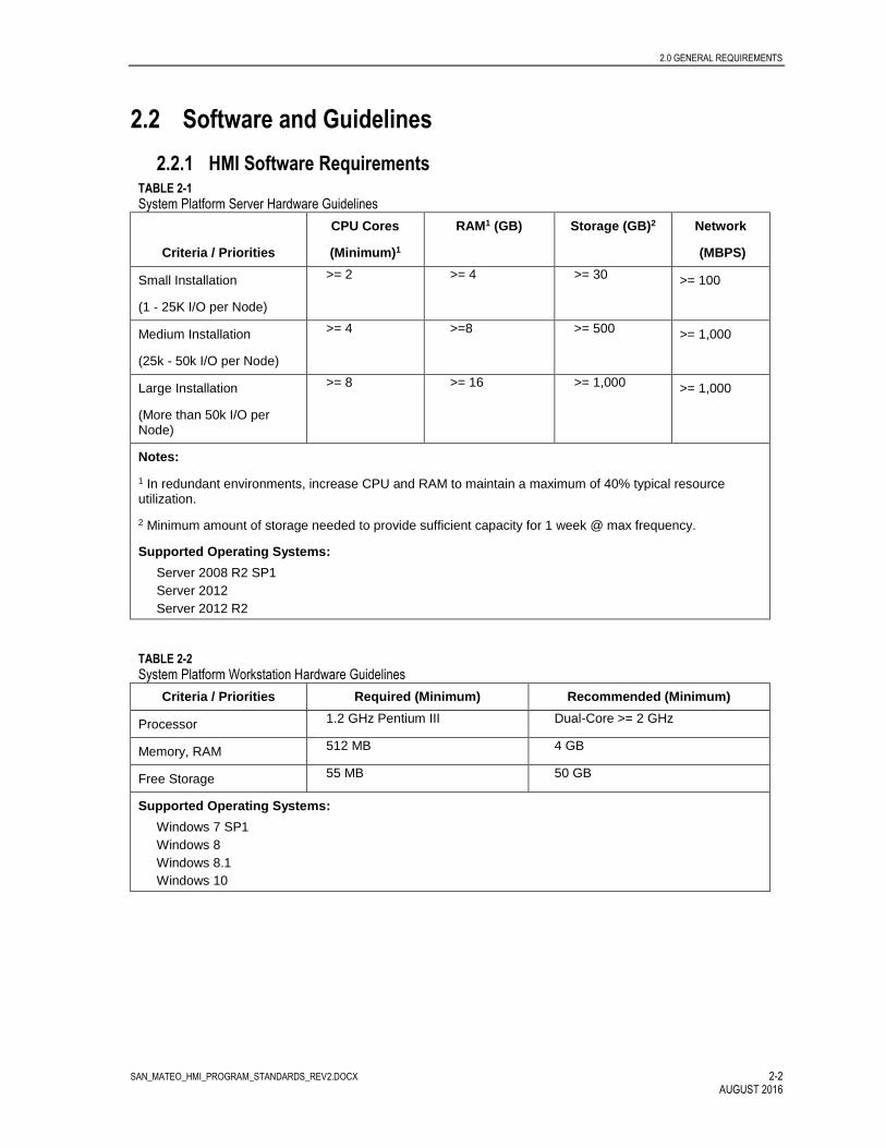
2.0 GENERAL REQUIREMENTS
SAN_MATEO_HMI_PROGRAM_STANDARDS_REV2.DOCX 2-2 AUGUST 2016
2.2 Software and Guidelines
2.2.1 HMI Software Requirements TABLE 2-1 System Platform Server Hardware Guidelines
Criteria / Priorities
CPU Cores
(Minimum)1
RAM1 (GB) Storage (GB)2 Network
(MBPS)
Small Installation
(1 - 25K I/O per Node)
>= 2 >= 4 >= 30 >= 100
Medium Installation
(25k - 50k I/O per Node)
>= 4 >=8 >= 500 >= 1,000
Large Installation
(More than 50k I/O per Node)
>= 8 >= 16 >= 1,000 >= 1,000
Notes:
1 In redundant environments, increase CPU and RAM to maintain a maximum of 40% typical resource utilization.
2 Minimum amount of storage needed to provide sufficient capacity for 1 week @ max frequency.
Supported Operating Systems:
Server 2008 R2 SP1
Server 2012
Server 2012 R2
TABLE 2-2 System Platform Workstation Hardware Guidelines
Criteria / Priorities Required (Minimum) Recommended (Minimum)
Processor 1.2 GHz Pentium III Dual-Core >= 2 GHz
Memory, RAM 512 MB 4 GB
Free Storage 55 MB 50 GB
Supported Operating Systems:
Windows 7 SP1
Windows 8
Windows 8.1
Windows 10
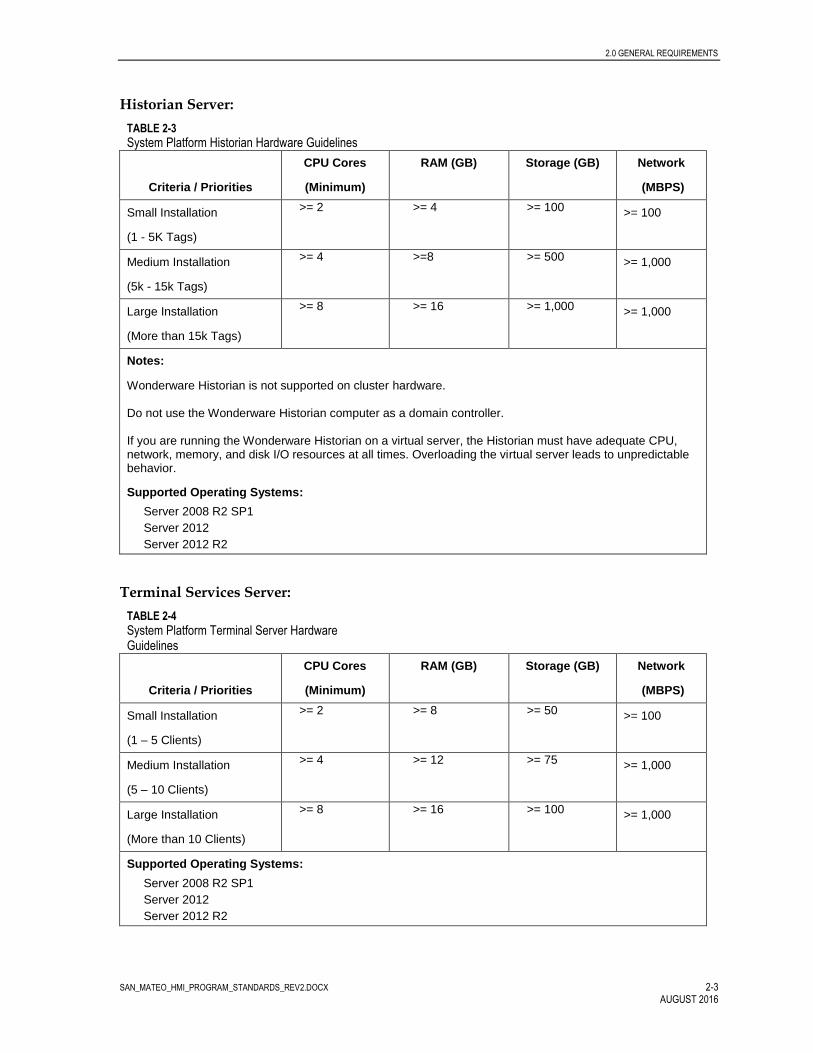
2.0 GENERAL REQUIREMENTS
SAN_MATEO_HMI_PROGRAM_STANDARDS_REV2.DOCX 2-3 AUGUST 2016
Historian Server:
TABLE 2-3 System Platform Historian Hardware Guidelines
Criteria / Priorities
CPU Cores
(Minimum)
RAM (GB) Storage (GB) Network
(MBPS)
Small Installation
(1 - 5K Tags)
>= 2 >= 4 >= 100 >= 100
Medium Installation
(5k - 15k Tags)
>= 4 >=8 >= 500 >= 1,000
Large Installation
(More than 15k Tags)
>= 8 >= 16 >= 1,000 >= 1,000
Notes:
Wonderware Historian is not supported on cluster hardware. Do not use the Wonderware Historian computer as a domain controller. If you are running the Wonderware Historian on a virtual server, the Historian must have adequate CPU, network, memory, and disk I/O resources at all times. Overloading the virtual server leads to unpredictable behavior.
Supported Operating Systems:
Server 2008 R2 SP1
Server 2012
Server 2012 R2
Terminal Services Server:
TABLE 2-4 System Platform Terminal Server Hardware Guidelines
Criteria / Priorities
CPU Cores
(Minimum)
RAM (GB) Storage (GB) Network
(MBPS)
Small Installation
(1 – 5 Clients)
>= 2 >= 8 >= 50 >= 100
Medium Installation
(5 – 10 Clients)
>= 4 >= 12 >= 75 >= 1,000
Large Installation
(More than 10 Clients)
>= 8 >= 16 >= 100 >= 1,000
Supported Operating Systems:
Server 2008 R2 SP1
Server 2012
Server 2012 R2

SAN_MATEO_HMI_PROGRAM_STANDARDS_REV2.DOCX 3-1 AUGUST 2016
3.0 HMI Graphics Layout and Navigation
3.1 Graphics Components
The HMI system is designed to convey information on the status of the facility as well as provide control functionality to allow for the operation of the facility. To that end, HMI applications will provide the following functionality:
Methods for logging into and out of the local HMI system for security purposes.
Methods to navigate between graphics screens for the various areas of a facility.
Standard pertinent operational information such as current alarms, date, time.
Detailed information on facility operations as well as methods for controlling the facility.
Access to operational control functions through security limited pop-up graphics.
To provide the required functionality HMI monitors are divided into four standard components including a Top Banner, Main Process area, Alarm Banner and Navigation area. The Top Banner, Main Process area and Alarm Banner are designed to fit a widescreen monitor format with a resolution of 1920x1200 with the Navigation area configured to be automatically hidden when not in use.
Figure 3-1 shows the standard layout applied to City of San Mateo HMI applications, as it would appear on an HMI monitor.
Figure 3-1 Layout on a standard HMI Monitor
Top Banner (1900 X 95)
Alarm Banner (1900 X 95)
Main Process Area (1900 X 1105) Navigation Bar (225 X 1200) Hidden in Normal View

3.0 HMI GRAPHICS LAYOUT AND NAVIGATION
SAN_MATEO_HMI_PROGRAM_STANDARDS_REV2.DOCX 3-2 AUGUST 2016
3.1.1 Top Banner
The Top Banner is fixed in place with a screen position of X:255, Y:0 and a size of 1900x95 pixels. The Top Banner is common to all screens provides the following information:
Arrow to Show the Main Navigation Menu
Log In and Log Out button
Back button
Forward button
Liquid Stream Process Flow Overview button
Solids Process Flow Overview button
Trends button
Alarm Summary (with the numbers of Level 1 and 2 alarms shown on the button).
Figure 3-2 shows a sample Top Banner which can be utilized for a typical City of San Mateo HMI application.
Figure 3-2 Sample Top Banner
3.1.2 Alarm Banner
The Alarm Banner will be shown on every HMI display. This Banner will only show the alarms from the highest two levels (Urgent and High). This banner will only show the unacknowledged alarms of these two levels on this banner.
A more detailed description of the alarm levels will be described in Chapter 7.
Figure 3-3 shows a sample Alarm Banner which can be utilized for a typical City of San Mateo HMI application.
Figure 3-3 Sample Alarm Banner
3.1.3 Navigation Bar
The Navigation area is the primary method by which users can transition from Main Overview (or Process Area) Screen to Main Overview (or Process Area) Screen within an HMI application. The navigation window will be configured into a tree structure which will appear when the user clicks on the Arrow on the top left hand corner of any display. No direct access to control function pop-up graphics is included in the navigation tree. The
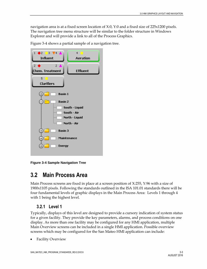
3.0 HMI GRAPHICS LAYOUT AND NAVIGATION
SAN_MATEO_HMI_PROGRAM_STANDARDS_REV2.DOCX 3-3 AUGUST 2016
navigation area is at a fixed screen location of X:0, Y:0 and a fixed size of 225x1200 pixels. The navigation tree menu structure will be similar to the folder structure in Windows Explorer and will provide a link to all of the Process Graphics.
Figure 3-4 shows a partial sample of a navigation tree.
Figure 3-4 Sample Navigation Tree
3.2 Main Process Area
Main Process screens are fixed in place at a screen position of X:255, Y:96 with a size of 1900x1105 pixels. Following the standards outlined in the ISA 101.01 standards there will be four fundamental levels of graphic displays in the Main Process Area: Levels 1 through 4 with 1 being the highest level.
3.2.1 Level 1
Typically, displays of this level are designed to provide a cursory indication of system status for a given facility. They provide the key parameters, alarms, and process conditions on one display. As more than one facility may be configured for any HMI application, multiple Main Overview screens can be included in a single HMI application. Possible overview screens which may be configured for the San Mateo HMI application can include:
Facility Overview

3.0 HMI GRAPHICS LAYOUT AND NAVIGATION
SAN_MATEO_HMI_PROGRAM_STANDARDS_REV2.DOCX 3-4 AUGUST 2016
Wet Stream Process Flow Overview
Solids Stream Process Overview
Control System Overview
Power Distribution System Overview The Facility Overview could be an image from Google Earth™ showing the entire plant. The two Process overviews will be similar to a Process Flow diagram. These two displays will show the equipment that is currently On in Red and will have links to the facilities that have critical (level 1) alarms.
3.2.2 Level 2
These displays typically contain more detail than the level 1 displays and are high level process displays. These are typically an operator’s primary operating display during normal operations for routine changes and monitoring. Displays of this level can include process unit overviews or primary displays for every major system. These displays are based on functionality and are meant to allow the operator to perform specific tasks using a limited number of displays and minimal navigation.
As an overall philosophy, the displays from Level 2 and below, the graphics will be a hybrid of High Performance HMI standards, while using some of 3-D symbols made available from Wonderware. Where possible the process flow will be shown starting from the left hand side of each graphic display.
The standard configuration for the equipment shown on this level and down (levels 3 and 4) shall be so that the tag identifier, description and engineering range shall be shown when the user mouse is hovered over the piece of equipment.
Navigation from one level 2 display to another will be using hyperlinked text.
Figure 3-5: Sample Navigation from Displays

3.0 HMI GRAPHICS LAYOUT AND NAVIGATION
SAN_MATEO_HMI_PROGRAM_STANDARDS_REV2.DOCX 3-5 AUGUST 2016
3.2.3 Level 3
These displays contain more detail than the Level 2 displays and are typically subsystem detail displays. These displays are where the operator performs non-routine operations such as lineup changes, equipment switching, or complex control related routine tasks.
Navigation to these displays will be from buttons on the Level 2 displays. Navigation away from this level of displays will be either from buttons or using the Hypertext standard shown for the Level 2 displays.
3.2.4 Level 4
This level is usually used for diagnostic displays. All system information should be available on displays at this level. These displays are not intended to be used for process or system control. On some occasions, displays of this level may not require a full-screen display allowing system information to be displayed in faceplates or a popup.
Navigation to these displays will be from buttons and these level displays will need to be closed to continue any other operation.

SAN_MATEO_HMI_PROGRAM_STANDARDS_REV2.DOCX 4-1 AUGUST 2016
4.0 Color and Graphic Standards
4.1 General
Table 4-1 shows the desired RGB numbers for objects within the project. The use of text, graphic symbol animation, colors etc. will be used to minimize the effects of color-blindness to the extent possible.
TABLE 4-1
Standard Color Conventions
Item Name Color Name Comments
Text - Heading Black: (RGB: 255, 255, 255) Tahoma, 12 point, Bold
Text - Labels Black: (RGB: 255, 255, 255) Tahoma, 11 point
Text – Descriptor Black: (RGB: 255, 255, 255) Tahoma, 8 point
Text – Tag name Black: (RGB: 255, 255, 255) Tahoma, 10 point, Bold
Text – Engineering Units Black: (RGB: 255, 255, 255) Tahoma, 8 point
Text - Process Value Blue: (RGB: 0, 0, 132) Tahoma, 12 point, Bold
Text – Set point Green: (RGB: 0, 132, 0) Tahoma, 12 point, Bold
Text – Navigation Links Blue: (RGB: 0, 0, 255) Tahoma, 11 point, Italic
Text within Control Buttons Black: (RGB: 255, 255, 255) Tahoma, 12 point
Displays (Background) Gray 2: (RGB: 224, 224, 224) Height - 1105, Width – 1900 / gray with no pattern
Menu Buttons Gray 2: (RGB: 224, 224, 224) Height – 83, Width - 87
Motor ON State Red: (RGB: 255, 0, 0)
Motor OFF State Gray 2: (RGB: 224, 224, 224)
Valve OPENED state Red: (RGB: 255, 0, 0)
Valve CLOSED state Gray 2: (RGB: 224, 224, 224)
Process Piping Gray 4: (RGB 192, 192, 192) Animated to show as ‘full’ when there is flow through that pipe.
4.2 Selection Buttons
Selector buttons can be configured in various colors and sizes where specific requirements warrant. Standard control function, where applicable, will utilize a format based on the following standards:
Style = 3D
Background Color = Gray 2
Back Style = Solid

4.0 COLOR AND GRAPHIC STANDARDS
SAN_MATEO_HMI_PROGRAM_STANDARDS_REV2.DOCX 4-2 AUGUST 2016
Font = Tahoma 12 pt
Width = 75
Height = 25
4.3 Numeric Data
Numeric data is split into numeric display and numeric input. Engineering Units associated with numerical values will be located external to the data display box and utilize the standard text configuration. Configuration of data will be specific to the data being displayed. However, the following default configuration will be implemented where appropriate:
Field length = variable
Decimal Place = variable
Format = decimal
Overflow = Round Value
Leading characters = blanks
Justification = center
Numeric inputs allow operators to input values such as set points. Differentiating numeric input values from numeric display values makes it easier for operators to distinguish between the two.
The visible attributes of numeric display of a typical analog values have a default configuration as shown below.
Figure 4-1: Standard Display for Analog values
The analog display shall be configured so that a mini-trend (for the past 24 hours) is shown with the analog value. The vertical scale shall represent the minimum and maximum of the engineering range.
The visible attributes of numeric input values have a default configuration including:
Background color = light orange
Foreground color = black
Text style = Tahoma, Bold, 10 pt

4.0 COLOR AND GRAPHIC STANDARDS
SAN_MATEO_HMI_PROGRAM_STANDARDS_REV2.DOCX 4-3 AUGUST 2016
Figure 4-2: Standard Display for Numeric Entry
4.4 Object Information and Colors
Various objects on the SCADA graphics will include levels of animation to provide an indication of equipment status. Animation allows for the physical appearance of a graphical object to be changed based on the value of an associated tag. Objects in which animation may be applied include valves, gates, pumps, fans, motors, etc.
In general, the following standards will be adopted for the symbols:
- Local / Remote switch status (from the field signal): ‘L’ or ‘R’ next to the piece of equipment. The L will be in a square, while the ‘R’ will be in box with rounded edges.
- Manual /Automatic status (from the HMI): ‘M’ or ‘A’ next to the piece of equipment. The ‘M’ will be in square, while the ‘A’ will be in a box with rounded edges.
- Fully Opened or Fully Closed Status (from the field signals): ‘O’ or ‘C’ next to the piece of equipment, in boxes with rounded edges. If the valve is fully opened, it will also be filled in red. A fully closed valve will be shown in gray.
- Valve or gate in Transition (or unknown): ‘T’ will be shown in an inverted triangle
- Valve or Gate position: analog value shown in a text box with the ‘%’ located outside the box.
- Equipment out of service or not ready: The symbol will have a yellow circle with a diagonal line across it.
- Pump On or Off (from the field signals): ‘O’ and ‘S’ (for off or stopped) will be in boxes with rounded edges next to the piece of equipment.
- Calibrate mode: A ‘C’ in cyan will be located adjoining the instrument. This setting will hold the last live data value and activate calibration timer.
- Test mode: A ‘T’ in cyan will be located adjoining the instrument. This setting will set the engineering units to an operator selected value.

4.0 COLOR AND GRAPHIC STANDARDS
SAN_MATEO_HMI_PROGRAM_STANDARDS_REV2.DOCX 4-4 AUGUST 2016
4.4.1 Valves and Gate Status
The standard valve or gate symbols are shown below:
Figure 4-3: Standard Symbols for Valves and Gates

4.0 COLOR AND GRAPHIC STANDARDS
SAN_MATEO_HMI_PROGRAM_STANDARDS_REV2.DOCX 4-5 AUGUST 2016
4.4.2 Motor, Pump, and Fan Status
The standard pump symbols are shown below:
Figure 4-4: Standard Symbols for Pumps and Motors
4.4.3 Instruments
The standard instrument symbols are shown below:

4.0 COLOR AND GRAPHIC STANDARDS
SAN_MATEO_HMI_PROGRAM_STANDARDS_REV2.DOCX 4-6 AUGUST 2016
Figure 4-5: Standard Symbols for Instruments

SAN_MATEO_HMI_PROGRAM_STANDARDS_REV2.DOCX 5-1 AUGUST 2016
5.0 Indication and Control Standards
5.1 Overview
The objective of this section is to establish standards used in the development of graphic objects and graphic control functions. This is required to maintain a common functionality across the enterprise. Common functionality is important to minimize the chance for operator errors due to implementing similar functions different ways.
5.2 Indication Standards
5.2.1 Analog Field Device
The following standard graphic applications will be used as a standard for analog points.
Figures 5-1 through 5-4 shows an example of a standard pop-up associated with an analog field device.
Figure 5-1 Standard Analog Pop-Up (Operations Tab)
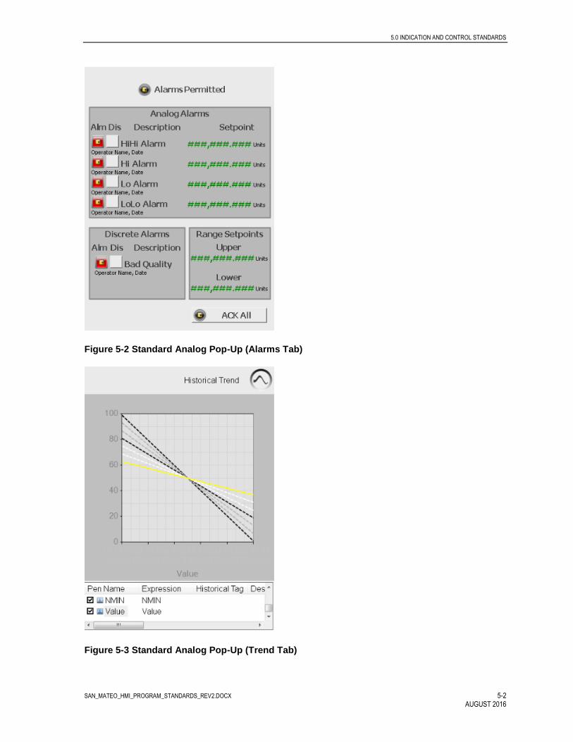
5.0 INDICATION AND CONTROL STANDARDS
SAN_MATEO_HMI_PROGRAM_STANDARDS_REV2.DOCX 5-2 AUGUST 2016
Figure 5-2 Standard Analog Pop-Up (Alarms Tab)
Figure 5-3 Standard Analog Pop-Up (Trend Tab)

5.0 INDICATION AND CONTROL STANDARDS
SAN_MATEO_HMI_PROGRAM_STANDARDS_REV2.DOCX 5-3 AUGUST 2016
Figure 5-4 Standard Analog Pop-Up (Maintenance Tab)
5.3 Levels of Control
For all the City of San Mateo control system graphic applications, two levels of control are defined: equipment control and system control. Equipment controls are associated with individual pieces of equipment such as a single motor, valve, or instrument. System controls are utilized for the operation and control of multi-equipment systems. All equipment and system control functions are implemented through the use of pop-up graphics.
5.3.1 Equipment Control
Graphic applications developed for City of San Mateo facilities will be configured to use a series of standard equipment level control graphics in the form of pop-up graphics.
Figures 5-5 through 5-8 shows an example of a standard equipment pop-up associated with a modulating valve.

5.0 INDICATION AND CONTROL STANDARDS
SAN_MATEO_HMI_PROGRAM_STANDARDS_REV2.DOCX 5-4 AUGUST 2016
Figure 5-5 Standard Modulating Valve Pop-Up (Operations Tab)
Figure 5-6 Standard Modulating Valve Pop-Up (Alarms Tab)

5.0 INDICATION AND CONTROL STANDARDS
SAN_MATEO_HMI_PROGRAM_STANDARDS_REV2.DOCX 5-5 AUGUST 2016
Figure 5-7 Standard Modulating Valve Pop-Up (Trend Tab)
Figure 5-8 Standard Modulating Valve Pop-Up (Maintenance Tab)

5.0 INDICATION AND CONTROL STANDARDS
SAN_MATEO_HMI_PROGRAM_STANDARDS_REV2.DOCX 5-6 AUGUST 2016
Figures 5-9 through 5-12 shows an example of a standard equipment pop-up associated with an open-close valve.
Figure 5-9 Standard Open-Close Valve Pop-Up (Operations Tab)
Figure 5-10 Standard Open-Close Valve Pop-Up (Alarms Tab)

5.0 INDICATION AND CONTROL STANDARDS
SAN_MATEO_HMI_PROGRAM_STANDARDS_REV2.DOCX 5-7 AUGUST 2016
Figure 5-11 Standard Open-Close Valve Pop-Up (Trend Tab)
Figure 5-12 Standard Open-Close Valve Pop-Up (Maintenance Tab)

5.0 INDICATION AND CONTROL STANDARDS
SAN_MATEO_HMI_PROGRAM_STANDARDS_REV2.DOCX 5-8 AUGUST 2016
Figures 5-13 through 5-16 shows an example of a standard equipment pop-up associated with a constant speed pump.
Figure 5-13 Standard Constant Speed Pump Pop-Up (Operations Tab)
Figure 5-14 Standard Constant Speed Pump Pop-Up (Alarms Tab)
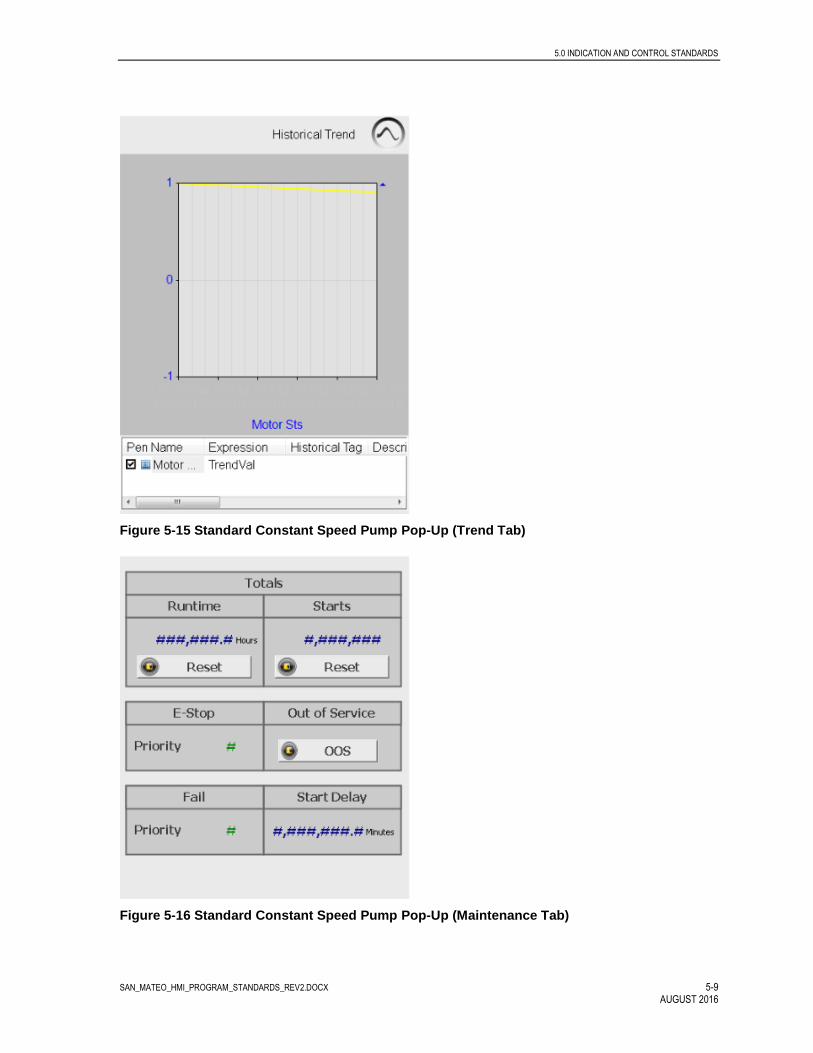
5.0 INDICATION AND CONTROL STANDARDS
SAN_MATEO_HMI_PROGRAM_STANDARDS_REV2.DOCX 5-9 AUGUST 2016
Figure 5-15 Standard Constant Speed Pump Pop-Up (Trend Tab)
Figure 5-16 Standard Constant Speed Pump Pop-Up (Maintenance Tab)

5.0 INDICATION AND CONTROL STANDARDS
SAN_MATEO_HMI_PROGRAM_STANDARDS_REV2.DOCX 5-10 AUGUST 2016
Figures 5-17 through 5-20 shows an example of a standard equipment pop-up associated with an adjustable speed pump.
Figure 5-17 Standard Adjustable Speed Pump Pop-Up (Operations Tab)
Figure 5-18 Standard Adjustable Speed Pump Pop-Up (Alarms Tab)

5.0 INDICATION AND CONTROL STANDARDS
SAN_MATEO_HMI_PROGRAM_STANDARDS_REV2.DOCX 5-11 AUGUST 2016
Figure 5-19 Standard Adjustable Speed Pump Pop-Up (Trend Tab)
Figure 5-20 Standard Adjustable Speed Pump Pop-Up (Maintenance Tab)

5.0 INDICATION AND CONTROL STANDARDS
SAN_MATEO_HMI_PROGRAM_STANDARDS_REV2.DOCX 5-12 AUGUST 2016
5.3.2 System Control
System level controls generally affect more than one equipment item, and are therefore applied to group systems. Each system level control pop-up is generally unique with the exception of standard PID controllers. Therefore, system control pop-ups are developed on an as needed basis. Though unique in nature, system control pop-ups are required to conform to the standards outlined in this document.
Typical system controls are provided for:
Lead/Lag selection
PID loop or multi-loop controls
Figures 5-21 through 5-23 are examples of a simple system control pop-up consisting two pumps in a lead lag sequence.
Figure 5-21 Lead / Lag Selection Pop-Up (Operations Tab)

5.0 INDICATION AND CONTROL STANDARDS
SAN_MATEO_HMI_PROGRAM_STANDARDS_REV2.DOCX 5-13 AUGUST 2016
Figure 5-22 Lead / Lag Selection Pop-Up (Trend Tab)
Figure 5-23 Lead / Lag Selection Pop-Up (Maintenance Tab)
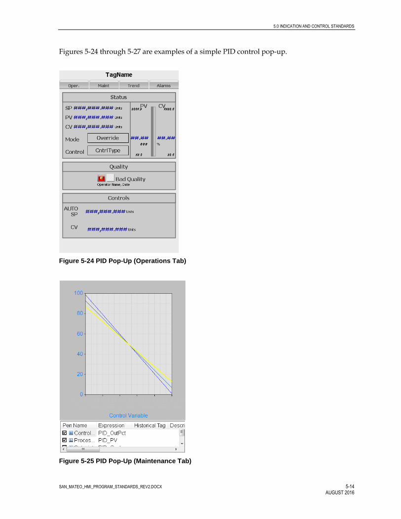
5.0 INDICATION AND CONTROL STANDARDS
SAN_MATEO_HMI_PROGRAM_STANDARDS_REV2.DOCX 5-14 AUGUST 2016
Figures 5-24 through 5-27 are examples of a simple PID control pop-up.
Figure 5-24 PID Pop-Up (Operations Tab)
Figure 5-25 PID Pop-Up (Maintenance Tab)

5.0 INDICATION AND CONTROL STANDARDS
SAN_MATEO_HMI_PROGRAM_STANDARDS_REV2.DOCX 5-15 AUGUST 2016
Figure 5-26 PID Pop-Up (Trend Tab)
Figure 5-27 PID Pop-Up (Operations Tab)
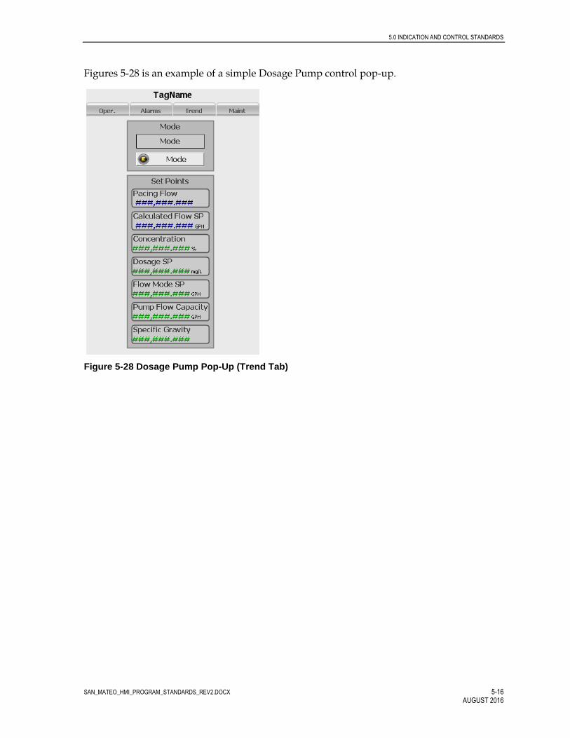
5.0 INDICATION AND CONTROL STANDARDS
SAN_MATEO_HMI_PROGRAM_STANDARDS_REV2.DOCX 5-16 AUGUST 2016
Figures 5-28 is an example of a simple Dosage Pump control pop-up.
Figure 5-28 Dosage Pump Pop-Up (Trend Tab)

SAN_MATEO_HMI_PROGRAM_STANDARDS_REV2.DOCX 6-1 AUGUST 2016
6.0 Additional Display Information
6.1 Trend Display Organization
Trends provide current information in a graphical format to describe how a process is running. This information can be used to determine how a process should be operated in the future to better meet government regulations or improve operating efficiency. Since trends require considerable system resources, trending requirements should be established early to allow for effective incorporation into the display design.
Trend data is generally provided from one of two sources including real time data or historical data. Real time data is used in cases where only current information is required with the data provided directly from an HMI tag. Historical data is used in cases where the option of reviewing past information is desired.
The standard Wonderware trend application can accommodate a number of pens representing individual data points. The ‘trend’ button shown on the top banner of all HMI displays, will open a new page. The operators will be able to create custom trends from this page, by picking the points to be shown on each trend and saving these trends. The standard Wonderware trending application provides the user with a lot of flexibility within this application. The user can select which points need to be shown on a custom trend by picking the points from the Historian. Thereafter, the user can define the color and range for each point. Each user can also change the time span for each trend. These trends can then be saved and accessed by any of the users of the system.
The system integrator shall work with the plant staff to establish all of the initial trends to be created with each system upgrade. For example, trend pages should be created for each process area with the important values for that area shown on one trend. The actual trend groups will be determined with the San Mateo staff based on the project needs. A list of proposed trends should be submitted to the San Mateo staff for approval prior to the witnessed system testing.
In addition to the Wonderware base Trend application, the programmer shall also use the ‘aahistClient’ application to create embedded trends for all of the analog values. These ‘mini’ trends will be displayed with each analog point as shown in Figure 4-1.
6.2 Control System Monitoring
The Control System Overview screen will provide general information on the health and status of the control system including network and control system I/O status. Network information will be displayed for:
Ethernet I/O Network
DeviceNet Network (where applicable)
ControlNet Network (where applicable)
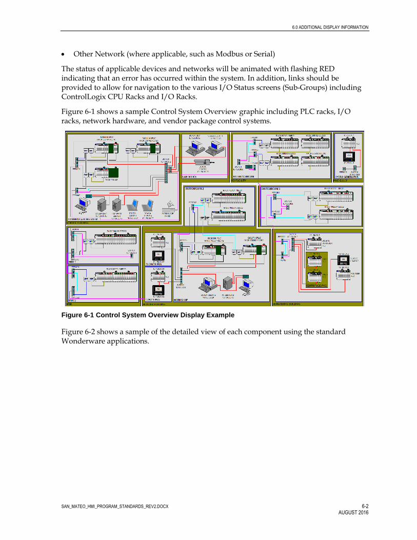
6.0 ADDITIONAL DISPLAY INFORMATION
SAN_MATEO_HMI_PROGRAM_STANDARDS_REV2.DOCX 6-2 AUGUST 2016
Other Network (where applicable, such as Modbus or Serial)
The status of applicable devices and networks will be animated with flashing RED indicating that an error has occurred within the system. In addition, links should be provided to allow for navigation to the various I/O Status screens (Sub-Groups) including ControlLogix CPU Racks and I/O Racks.
Figure 6-1 shows a sample Control System Overview graphic including PLC racks, I/O racks, network hardware, and vendor package control systems.
Figure 6-1 Control System Overview Display Example
Figure 6-2 shows a sample of the detailed view of each component using the standard Wonderware applications.

6.0 ADDITIONAL DISPLAY INFORMATION
SAN_MATEO_HMI_PROGRAM_STANDARDS_REV2.DOCX 6-3 AUGUST 2016
Figure 6-2 Example of a Control System Display for each component

SAN_MATEO_HMI_PROGRAM_STANDARDS_REV2.DOCX 7-1 AUGUST 2016
7.0 Alarm Management
Alarms are used within an HMI application to indicate an adverse process condition or to bring attention to potential problems with equipment.
The alarming standards for the San Mateo HMI application will be created using the framework of the ANSI/ISA 18.2 Alarm Management Standard. Based on this standard philosophy, the City should address the topic of alarm management as a process that involves design, implementation, operation, monitoring, maintenance and change management. Figure 7-1 is an illustration of the lifecycle model that should be adopted by the City.
Figure 7-1 Alarm Management Lifecycle
At the onset it is critical that the City develops an alarm philosophy that documents the objectives of the alarming system. This philosophy document should also outline the process for the stages following the design and implementation of the alarms with the

7.0 ALARM MANAGEMENT
SAN_MATEO_HMI_PROGRAM_STANDARDS_REV2.DOCX 7-2 AUGUST 2016
control system. It is important to have a documented process to monitor and assess the performance of the alarming system on an annual basis. This will lead to a documented process to manage the change of the alarms and alarming standards. The first step would be for the Contractor to work with the City to develop a matrix as shown below that detail the issues and consequences. The table shown below is a sample matrix during the initial alarm workshop.
TABLE 7-1 Sample Alarming Criteria and Priorities
Criteria / Priorities Level 1 / Urgent Level 2 / High Level 3 /
Medium Level 4 / Low
Cost / Financial Loss / Downtime
- Cost greater than $100K
- Requires Snr Management Reporting
- Shutdown of treatment
- Cost between $10K and $100K
- Requires Reporting
- Short duration of outage
- Cost less than 10K
- Requires Internal Reporting
- No outage
No Loss
Environmental damage and public perception
- Involved community and multiple complaints
- Uncontained release of hazardous materials
- Extensive cleanup
- Contamination causes non-permanent damage
- Single or few complaints
- Requires reporting to a local or state agency
- Contained release
- Internal report
No Effect
Response Time - Less than 5 minutes
- Between 5 and 15 minutes
- Between 15 minutes and 1 hour
Over 1 hour
Health and Safety - Extremely hazardous conditions
- Dangerous conditions
-
7.1 Alarm Priorities
The alarm management system will provide the capability to assign each alarm within a group to four alarm priorities: Critical, Urgent, High and Low. The alarms are assigned a priority value of 1 (Critical) to 4 (Alarm).
Out Of Service indications will be assigned a priority of 8 and will not be displayed on the regular alarm displays. There will be a special alarm page configured to display all Out Of Service equipment. Priority alarms 1 and 2 will be sent for remote annunciation, using the WIN-911 software. Alarm priority 3, 4 and 8 alarms will not sent to the WIN-911 software.
7.1.1 Critical Alarms (Level 1)
These Critical alarms (priority 1) are typically alarms that involve personnel safety or which require immediate operator attention. Some of the typical Level 1 alarms are:

7.0 ALARM MANAGEMENT
SAN_MATEO_HMI_PROGRAM_STANDARDS_REV2.DOCX 7-3 AUGUST 2016
High-High Hydrogen sulfide, H2S
High-High, Lower Explosive Limit LEL
Chemical shower in use
This level alarm will be displayed as shown below with two exclamation marks within a purple circle inside a black square.
Figure 7-2 Symbol for Level 1 Alarms
7.1.2 Urgent Alarms (Level 2)
These urgent process alarms (priority 2) would typically be alarms that require immediate action, such as permit violations and/or equipment damage. Some examples would be.
Effluent pumping station (EPS) pump failure
High-high influent pump station (IPS) level
High-high EPS level
This level alarm will be displayed as shown below with one exclamation mark within an orange diamond inside a black square.
Figure 7-3 Symbol for Level 2 Alarms
7.1.3 High Alarm (Level 3)
Medium-priority alarms (priority 3) are those alarms that require operator attention, but not necessarily immediately. Some examples would be:
High LEL
High/low levels
Equipment failures
This level alarm will be displayed as shown below with one exclamation mark within a dark yellow rectangle inside a black square.
Figure 7-4 Symbol for Level 3 Alarms
7.1.4 Alarm (Level 4)
Alarms (priority 4) are informational and are designed to help the operator understand current operating conditions and make informed decisions. A typical example would be:
!!
!
!
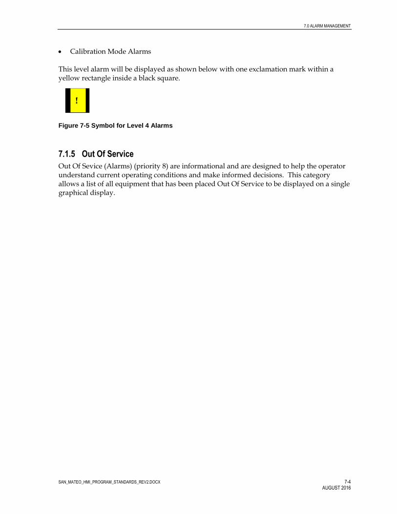
7.0 ALARM MANAGEMENT
SAN_MATEO_HMI_PROGRAM_STANDARDS_REV2.DOCX 7-4 AUGUST 2016
Calibration Mode Alarms This level alarm will be displayed as shown below with one exclamation mark within a yellow rectangle inside a black square.
Figure 7-5 Symbol for Level 4 Alarms
7.1.5 Out Of Service
Out Of Sevice (Alarms) (priority 8) are informational and are designed to help the operator understand current operating conditions and make informed decisions. This category allows a list of all equipment that has been placed Out Of Service to be displayed on a single graphical display.
!

SAN_MATEO_HMI_PROGRAM_STANDARDS_REV2.DOCX 8-1 AUGUST 2016
8.0 Glossary
AOI Add-On Instruction – Reusable PLC programming instruction, created by the programmer, to provide specific control functions or features
Back Plane Interfaced used to pass data into and out of modules. The backplane can be physical (ControlLogix IO rack) or virtual (CompactLogix, which does not include a separate IO rack)
Base Rack IO rack containing a PLC CPU. May or may not include IO modules
Button Dynamic object used to perform a specified function(s) one time when activated. Common functions include Start, Stop, Reset, Set to Auto, move data, change state, etc.
CPR Coordinated Product Release – Term used by Rockwell Software to define a suite of software and hardware firmware levels tested by Rockwell Software and certified to work together. For City of San Mateo control system projects all software used and hardware firmware will be CPR9 compliant.
CTD down counter
CTU up counter
Display/Graphic Refers to the text and graphics in an individual window.
Dynamic Object A graphic object on a screen with associated actions. Sample actions include blinking, change of color, change of position, and change in visibility, etc.
Event Instruction The EVENT instruction is used to trigger one execution of an event task.
Event Task A task that performs a specific function when triggered by a specified event. When the event task is triggered, it interrupts any lower priority tasks, executes one time, and returns control to the task that was interrupted, at the point at which it was interrupted.
Human-machine interface An open architecture operator interface that is configured using object technology
Input/Output External signals interfaced to the PLC control system. Can be hard wired or networked from physical devices (transmitters, motors, etc) or software applications (HMI, Historian Data Collector, Etc)

8.0 GLOSSARY
SAN_MATEO_HMI_PROGRAM_STANDARDS_REV2.DOCX 8-2 AUGUST 2016
IO Module Input or Output module, installed within an IO Rack, used to provide a hardwired interface to field devices such as transmitters or motors
IO Rack For modular-based PLC control system, the IO Rack is the base structure used to house the various modules making up the PLC control system
Navigation Graphic Graphic window configured for the sole purpose of allowing the activation of the Overview Graphics
Numeric Indicator Dynamic object used to display numeric information on graphics.
Numeric Input Dynamic object used to provide a mode for the input of numeric data (such as set points) on a graphic
Object Keys An object key is a key or key sequence that is associated with a graphic object and has had its usual action redefined by assigning a command or macro to it. An object key can have separate press, repeat, and release actions assigned.
Overview Graphic Primary graphic used for the display of process and control system information.
Parameter File A text file used to link tag place holder values with specific data tags.
Pop-Up Graphic A secondary graphic that is activated from another graphic, usually through the use of a dynamic object.
Process Variable Values are numeric data links that display the value of process variables such as flows, pressure, and levels.
Screen Refers to the entire face of a computer monitor.
Selector Dynamic object used to allow selection from one of multiple available states.
UDT User Defined Data Type (Data structure used within PLC Control program).

City of San Mateo Clean Water Program Control System PLC Programming
Standards Revision 3
Prepared for
City of San Mateo JULY, 2017
Prepared by CH2M

SAN_MATEO_PLC_PROGRAM_STANDARDS_REV3 ii V 1.2 April 16, 2010
Contents
Section Page 1.0 Introduction ......................................................................................................................... 1-1
1.1 Purpose .................................................................................................................... 1-1 1.1.1 Target Audience ........................................................................................ 1-1
1.2 Hardware Standards .............................................................................................. 1-1 1.2.1 General ........................................................................................................ 1-1 1.2.2 Large Control System Components ........................................................ 1-2
1.3 PLC Software Standards ........................................................................................ 1-3
2.0 PLC Software Development ............................................................................................. 2-1 2.1 Program Structure .................................................................................................. 2-1 2.2 IO Configuration .................................................................................................... 2-1
2.2.1 Ethernet Card Configuration – ControlLogix ....................................... 2-2 2.2.2 ControlNet Card Configuration – ControlLogix .................................. 2-2 2.2.3 DeviceNet Card Configuration – ControlLogix .................................... 2-3 2.2.4 Analog Input Card Configuration – ControlLogix ............................... 2-3 2.2.5 Analog Output Card Configuration – ControlLogix............................ 2-4 2.2.6 Digital Input Card Configuration – ControlLogix ................................ 2-5 2.2.7 Digital Output Card Configuration – ControlLogix ............................ 2-5
2.3 PLC Tag Database .................................................................................................. 2-5 2.3.1 Controller Scope and Program Scope ..................................................... 2-6 2.3.2 Base Tags and Alias Tags ......................................................................... 2-6 2.3.3 Produced Tags and Consumed Tags ...................................................... 2-7
2.4 PLC Control Code .................................................................................................. 2-7 2.4.1 Tasks ............................................................................................................ 2-8 2.4.2 Programs ..................................................................................................... 2-9 2.4.3 Routines ...................................................................................................... 2-9
3.0 Tagging/Naming Conventions......................................................................................... 3-1 3.1 PLC Naming Conventions .................................................................................... 3-1
3.1.1 PLC File and Controller Names .............................................................. 3-1 3.1.2 PLC Hardware Names (Communication and IO modules) ................ 3-1 3.1.3 ControlLogix Task Names ....................................................................... 3-2 3.1.4 ControlLogix Program File Names ......................................................... 3-2 3.1.5 ControlLogix Routine Names .................................................................. 3-2
3.2 PLC Software Tagging Criteria ............................................................................ 3-3 3.2.1 Tagging Overview ..................................................................................... 3-3 3.2.2 Tag Numbering Format ............................................................................ 3-3
4.0 User-Defined Elements ..................................................................................................... 4-1 4.1 General ..................................................................................................................... 4-1
4.1.1 User Data Type .......................................................................................... 4-1 4.2 Add-On Instructions .............................................................................................. 4-4

CONTENTS
SAN_MATEO_PLC_PROGRAM_STANDARDS_REV3 iii JULY, 2017
5.0 PLC Program Documentation .......................................................................................... 5-1 5.1 Routine Documentation ........................................................................................ 5-1 5.2 Tag Descriptions ..................................................................................................... 5-2
6.0 PLC Program Development .............................................................................................. 6-1 6.1 General ..................................................................................................................... 6-1 6.2 Tags and Data ......................................................................................................... 6-2
6.2.1 Analog Input Data ..................................................................................... 6-4 6.2.2 Messaging Data between PLCs ............................................................... 6-4 6.2.3 Standard Program Structure .................................................................... 6-5
7.0 PLC Programming Best Practices .................................................................................... 7-1 7.1 Simplify Rungs of Code ......................................................................................... 7-1 7.2 Data Types ............................................................................................................... 7-2 7.3 Prefacing Conditions .............................................................................................. 7-2 7.4 Discrete Controls .................................................................................................... 7-3 7.5 Equations ................................................................................................................. 7-3 7.6 Timers....................................................................................................................... 7-3 7.7 Counters ................................................................................................................... 7-4 7.8 Button Control ........................................................................................................ 7-5 7.9 Sequence Control .................................................................................................... 7-6 7.10 PID Control ............................................................................................................. 7-6 7.11 SCADA Set points .................................................................................................. 7-6 7.12 Alarming .................................................................................................................. 7-7
8.0 Glossary ................................................................................................................................ 8-1 Tables Table 4-1 Approved UDT ................................................................................................................ 4-3
Figures Figure 2-1 Sample IO Configuration .............................................................................................. 2-2 Figure 2-2 Sample Program Configuration ................................................................................... 2-8 Figure 4-1 Sample Non-optimized UDT Configuration ............................................................. 4-2 Figure 4-2 Sample Optimized UDT Configuration ..................................................................... 4-2 Figure 4-3 Sample Tag ..................................................................................................................... 4-4 Figure 4-4 Access to Add-On Instructions .................................................................................... 4-5 Figure 5-1 Sample Ladder Routine ................................................................................................ 5-1 Figure 5-2. Sample Function Block Routine .................................................................................. 5-2 Figure 5-4 Sample Tag Descriptions and Tag Names ................................................................. 5-3 Figure 6-3. Analog Tag Aliased to Analog Input Card ............................................................... 6-4 Figure 7-1 Complicated Rungs of Ladder Code ........................................................................... 7-1 Figure 7-2 Simplified Rungs of Ladder Code ............................................................................... 7-2 Figure 7-3 Prefacing Conditions in Ladder ................................................................................... 7-3 Figure 7-5 Counter Using CTU ....................................................................................................... 7-4 Figure 7-6 Counter Using ADD ...................................................................................................... 7-5 Figure 7-7 Two-State Toggle Control ............................................................................................. 7-5

CONTENTS
SAN_MATEO_PLC_PROGRAM_STANDARDS_REV3 iv JULY, 2017
Figure 7-8 Sample SCADA Setpoints............................................................................................. 7-7 Figure 7-9 Sample Alarm Cascading Interlock............................................................................. 7-7

SAN_MATEO_PLC_PROGRAM_STANDARDS_REV3 v AUGUST 2016
Acronyms and Abbreviations
A/M auto/manual
A-B Allen-Bradley
AI analog input
AO analog output
AOI Add-On Instruction
BOOL Boolean
cfm cubic feet per minute
CPR Coordinated Product Release
CPT compute block
CV control variable
DI discrete input
DINT double integer – 32 bits
DO discrete output
FB function block
ft3/minute cubic feet per minute
FVNR full-voltage non-reversing
FVR full-voltage reversing
gph gallons per hour
gpm gallons per minute
GUI graphical user interface
HMI human-machine interface
INT integer – 16 bits
IO Input / Output
JSR jump to subroutine command
LAD ladder
mgd million gallons per day
MSG message commands
NOP No Operation Command
ODVA Open DeviceNet Vendors Association

ACRONYMS AND ABBREVIATIONS
SAN_MATEO_PLC_PROGRAM_STANDARDS_REV3 vi JULY, 2017
PCS Process Control System
PID Proportional Integral Derivative
P&ID process and instrumentation diagram
PLC programmable logic controller
PV process variable
RTH run time hours
SCADA Supervisory Control and Data Acquisition
SFC sequential function chart
SINT single integer – 8 bits
SP Set point
ST structured text
T&D treatment and disposal
TBD to be determined
UDT User-defined Data Type
VSD variable-speed drive

SAN_MATEO_PLC_PROGRAM_STANDARDS_REV3 1-1 AUGUST 2016
1.0 Introduction
1.1 Purpose The purpose of this document is to establish the City of San Mateo enterprise-wide programmable logic controller (PLC) program standards as applied to plant control systems utilizing Allen-Bradley (A-B) ControlLogix hardware. Hardware and software standards are needed to provide uniformity across multiple control system projects. Specific goals include:
• Provide a common structure and program development methodology for all PLC programs
• Define standards for PLC program development as applied to A-B ControlLogic hardware platforms.
• Reduce installation and maintenance of both PLC and human-machine interface (HMI) programs thus reducing the City’s operating expenses and capital expenditures.
For further reference and additional information, please refer to the following documents.
• City of San Mateo Clean Water Program Control System HMI Programming Standards • City of San Mateo Clean Water Program Design Standard 05 – Equipment and Instrument
Identification Standards
1.1.1 Target Audience It is expected that users of this document will have a general knowledge of PLC based control systems and a working knowledge of the A-B ControlLogix hardware platforms. In addition, users should have a working knowledge of the Common Industrial Protocol (CIP) communications including their configuration and operation.
1.2 Hardware Standards 1.2.1 General The City of San Mateo control system is based on the A-B ControlLogix Redundant PLC for primary control, which is the latest in the progression of A-B control hardware. Field devices such as motors, valves, and instruments will interface to the control system through a series of IO racks. Field device interface can be hardwired between the field device and an IO module, providing individual equipment signals per wire set. Or signals can be networked between field devices and a communication module providing for multiple equipment signals per wire set.
The system will use several modes of communication to achieve the required system functionality, including the following.
1.0 INTRODUCTION
SAN_MATEO_PLC_PROGRAM_STANDARDS_REV3 1-2 JULY, 2017
• Ethernet IP Communications: The Ethernet network will provide the connection between PLCs and the Supervisory Control And Data Acquisition (SCADA) system. In addition, PLC-to-PLC communications will primarily use the Ethernet network.
• ControlNet Communications: Remote racks (a rack housing communications and/or IO modules but not including a CPU) can communicate with their parent PLC via a ControlNet communications network. For control systems utilizing ControlNet communications, the primary input/output (IO) rack (IO rack containing a CPU) will include at least one ControlNet communications module. The primary IO rack can contain multiple ControlNet communications modules providing for multiple ControlNet networks for a single CPU. All remote IO racks included in the ControlNet system will then include one ControlNet communications module to be located in the first slot of the rack (slot 0).
− Non-redundant PLC systems: ControlNet module in primary rack will be configured as the ControlNet network master and include the lowest node number on the network.
− Redundant PLC systems: ControlNet modules in primary redundant racks will NOT be configured as the ControlNet network master. Node numbers for redundant CPU racks to be configured to reduce the likelihood of redundant rack ControlNet modules becoming the network master.
• DeviceNet Communications: Any device which complies with the Open DeviceNet Vendors Association (ODVA) open protocol standards for DeviceNet devices can be integrated into a DeviceNet network installed as part of a the City’s facility control system. For the City’s wastewater treatment facilities, this will primarily include (but not be limited to) adjustable speed drives. DeviceNet communication modules can reside in a primary PLC rack or in PLC remote racks. Multiple DeviceNet networks can be included within a facility control system. The design intent is to limit the number of nodes on any single network to 32 devices. In addition to ASDs, most motorized and control valves could also be controlled via a DeviceNet network.
Stand-alone control systems provided as part of a vendor package system or control systems with minimal IO may be classified as a small control system if the total number of modules (IO and communications) does not exceed 7. Control systems fitting these criteria will have the option of using the Allen-Bradley CompactLogix platform. All other PLC hardware shall be based on the standard control system equipment. All PLC-based control systems implemented for the City projects will use approved hardware selected from the lists in the adjoining sections.
1.2.2 Large Control System Components All A-B control hardware and software will be Coordinated Product Release 9 (CPR9) compliant. Hardware module types and firmware revision numbers indicated below are minimum base requirements. The actual modules used in a system shall be based upon the project specific design and specifications. Any deviation from the following listed components must be approved by the City prior to being used. The base design is based upon the 16 point DI card, but the 32 point DI card can be used at the discretion of the City.

1.0 INTRODUCTION
SAN_MATEO_PLC_PROGRAM_STANDARDS_REV3 1-3 JULY, 2017
All modules will have firmware set to most current revision number that is compatible with the version of the Enhanced Redundancy Module used in the base project (V27), provided that the latest firmware revisions maintain compatibility with existing systems. Ensure all software revisions and patch levels are at the same level throughout the integrated system.
1.3 PLC Software Standards The following standard software packages are required to develop plant control system PLC programs and meet standards developed by the City.
Rockwell Automation – RSLogix5000 Version 27 Rockwell Automation – RSNetworx for DeviceNet Version 21.01.00 Rockwell Automation – RSNetworx for ControlNet Version 21.01.00 Rockwell Automation – ControlFlash Version 12.00.00
NOTE: ControlFlash software is used to flash the firmware revisions of ControlLogix and CompactLogix cards to the desired level. The latest firmware files can be found at: http://support.rockwellautomation.com/ControlFlash/. For ControlLogix, the processor flash firmware must be updated lock-step with the RSLogix 5000 version. For other modules, you only need to update the flash firmware if you want the new feature/functionality described in the release note. It is not recommend updating these other modules ahead of the programming software as it may not be compatible. The manual for using ControlFlash can be found at: http://literature.rockwellautomation.com/idc/groups/literature/documents/qs/1756-qs105_-en-e.pdf.

SAN_MATEO_PLC_PROGRAM_STANDARDS_REV3 2-1 AUGUST 2016
2.0 PLC Software Development
2.1 Program Structure An A-B ControlLogix PLC program includes three main components, which work together to form the overall PLC program. The components of the PLC program include:
• IO configuration • PLC program internal tag database • Control code
2.2 IO Configuration The IO configuration provides a map for the CPU to define modules (IO and communication) included in the control system as well as their locations within the system. The IO configuration also serves to tell the CPU what version of hardware is being used in the control system and to set the data transfer rate between the CPU and the modules. The IO configuration is based on design documents created by the design Engineers for the control system. Design documents can include:
• Process and instrumentation diagram (P&IDs) • Process control narratives • Control system layout drawings • IO list
Configuration of the system is done by the programmer at the start of system programming. Configuration entails selecting modules, placing modules in appropriate locations, providing suitable module names, and setting module parameters.
The sample configuration in Figure 2-1, Sample I/O Configuration, shows the CPU at slot [0] and includes a default indication of device type (1756-L61) and a programmer-assigned name (_59PLC100). Remaining modules include communications and IO modules.
The following sections detail the standard configuration settings for each major type of module based on the module types specified in Section 1.2. Any deviations from the standard configuration must be approved by The City prior to system development.

2.0 PLC SOFTWARE DEVELOPMENT
SAN_MATEO_PLC_PROGRAM_STANDARDS_REV3 2-2 JULY, 2017
Figure 2-1 Sample IO Configuration
2.2.1 Ethernet Card Configuration – ControlLogix Each Ethernet module will include the following configuration settings.
Ethernet Card Configuration Settings General Tab
IP Address As Assigned by the City of San Mateo Revision 4 Electronic Keying Compatible Keying
Connection Tab Requested Packet Interval N/A Inhibit Module Not Checked Major Fault On Controller If… Not Checked
2.2.2 ControlNet Card Configuration – ControlLogix Each ControlNet module will include the following configuration settings.
ControlNet Card Configuration Settings General Tab
Comm Format Rack Optimized (for Remote Racks) Node As Assigned Revision 20.11 Electronic Keying Compatible Keying
Connection Tab Requested Packet Interval 100 ms

2.0 PLC SOFTWARE DEVELOPMENT
SAN_MATEO_PLC_PROGRAM_STANDARDS_REV3 2-3 JULY, 2017
ControlNet Card Configuration Settings Inhibit Module Not Checked Major Fault On Controller If… Not Checked
Refer to the Rockwell Software ControlNet module user guide for information on network configuration (PN 957988-68).
2.2.3 DeviceNet Card Configuration – ControlLogix Each DeviceNet module will include the following configuration settings.
DeviceNet Card Configuration Settings General Tab
Node 1 Revision 11 Electronic Keying Compatible Keying Input Size 124 Output Size 123 Status Size 32
Connection Tab Requested Packet Interval 100 ms Inhibit Module Not Checked Major Fault On Controller If… Not Checked
Refer to the Rockwell Software DeviceNet module user guide for information on network configuration (PN 955134-55).
2.2.4 Analog Input Card Configuration – ControlLogix Each analog input module will include the following configuration settings.
Analog Input Card Configuration Settings General Tab (Module Definition)
Series A Revision 1 Electronic Keying Compatible Module Connection Data Input Data Analog and HART PV Coordinated System Time Time stamped Data Format Float
Connection Tab Requested Packet Interval 100 ms Inhibit Module Not Checked Major Fault On Controller If… Not Checked Use Scheduled Connection… Checked (If in Remote Rack)
Configuration Tab – All Channels RTS 100 ms Module Filter [-3 db] 50 Hz

2.0 PLC SOFTWARE DEVELOPMENT
SAN_MATEO_PLC_PROGRAM_STANDARDS_REV3 2-4 JULY, 2017
Analog Input Card Configuration Settings
Enable HART Checked for all HART Devices Not checked for non-HART Devices
Keep HART replies 15 Seconds (HART) Pass Through Once per Module Scan Input Range 0 ma to 20 ma Sensor Offset 0.0 Digital Filter 0 Scaling: High Signal 20.0 Scaling: Low Signal 4.0 Scaling: High Engineering 20.0 Scaling: Low Engineering 4.0
Calibration Tab Do not make changes to this tab unless fully versed in calibration procedures associated with the analog input module.
2.2.5 Analog Output Card Configuration – ControlLogix Each analog output module will include the following configuration settings.
Analog Output Card Configuration Settings General Tab
Comm Format Float Data Revision 1 Electronic Keying Compatible Keying
Connection Tab Requested Packet Interval 100 ms Inhibit Module Not Checked Major Fault On Controller If… Not Checked Use Scheduled Connection… Checked (If in Remote Rack)
Configuration Tab – All Channels Output Range 0 ma to 20 ma Sensor Offset 0.0 Hold for Initiation As required Scaling: High Signal 20.0 Scaling: Low Signal 4.0 Scaling: High Engineering 100.0 Scaling: Low Engineering 0.0
Output State Tab – All Channels Output State in Program Mode Hold Last State Output State in Fault Mode Hold Last State Communications Failure Change outputs to Fault Mode state
Limits Tab – All Channels Disable All Alarms Checked Latch Limit Alarms Not Checked High Clamp 100 Low Clamp 0 Ramp in Run Mode Not Checked

2.0 PLC SOFTWARE DEVELOPMENT
SAN_MATEO_PLC_PROGRAM_STANDARDS_REV3 2-5 JULY, 2017
Analog Output Card Configuration Settings Calibration Tab
Do not make changes to this tab unless fully versed in calibration procedures associated with the analog output module.
2.2.6 Digital Input Card Configuration – ControlLogix Each digital input module will include the following configuration settings.
Digital Input Card Configuration Settings General Tab
Comm Format Input Data (If in Local Rack) Rack Optimized (If in Remote Rack)
Revision 3 Electronic Keying Compatible Keying
Connection Tab Requested Packet Interval 100 ms if Local Rack, N/A if Remote Rack Inhibit Module Not Checked Major Fault On Controller If… Not Checked
Configuration Tab Enable Change of State: Off -> On Not Checked Enable Change of State: On -> Off Not Checked Input Filter Time: ALL 1 ms
2.2.7 Digital Output Card Configuration – ControlLogix Each digital output module will include the following configuration settings.
Digital Output Card Configuration Settings General Tab
Comm Format Output Data (If in Local Rack) Rack Optimized (If in Remote Rack)
Revision 3 Electronic Keying Compatible Keying
Connection Tab Requested Packet Interval 100 ms if Local Rack, N/A if Remote Rack Inhibit Module Not Checked Major Fault On Controller If… Not Checked
Configuration Tab Output State in Program Mode Hold Last State
Output State in Fault Mode Off (change as necessary based on equipment requirements)
Major Fault On Controller If… Change outputs to Fault Mode state
2.3 PLC Tag Database The tag database is used to define storage locations within the PLC for data used in the processing of control code. The tag database is created from a number of sources including the PLC IO configuration documents and the physical device IO list design documents.
2.0 PLC SOFTWARE DEVELOPMENT
SAN_MATEO_PLC_PROGRAM_STANDARDS_REV3 2-6 JULY, 2017
When the PLC’s IO configuration is developed (based on standards outlined in Section 2.2), the PLC creates default database tags to define storage locations for data received from and sent to control modules. Default tag names for these locations do not lend themselves easily to use through the PLC program. Therefore, a standard programming procedure is used to create additional tags, which better define the intended purpose or data source. After creation of the additional tags, the default data is mapped to the better defined data locations. For input data (discrete and analog inputs), this has the added benefit of ensuring that inputs maintain a consistent state for one entire program cycle scan.
The IO list, which is created as part of the control system design, provides a list of physical devices connected to the control system. Some devices, such as transmitters, are hard-wired to IO modules. Other devices, such as motor starters, can be connected through a communications network such as DeviceNet. Database tags are created for these field devices to define storage locations for their data.
With the exception of the default tags for IO modules, all other tags in the database are created manually by the programmer. Utilizing the import/export capabilities of the RSLogix programming environment, the time needed to configure the tag database can be reduced through the use of spreadsheet applications such as Microsoft Excel™.
2.3.1 Controller Scope and Program Scope PLC tags can be controller scoped or program scoped. Controller-scoped tags are configured such that they are accessible by all parts of the control program as well as being accessible to applications outside of the PLC, such as the SCADA system.
Program-scoped tags are configured within a separate data memory area associated with a program. Within the PLC program they are only accessible by the program in which they are configured. This allows for the ability to use a common tag name multiple times across a number of separate programs. This can find use when applying standardized control code across multiple programs.
For data dedicated to transfer to/from an external application, such as the SCADA/HMI systems, either individual tags or user-defined data type (UDT) controller scoped tags may be used. If a UDT tag is used, it should only contain data that is normally used by the external application.
2.3.2 Base Tags and Alias Tags RSLogix5000 allows for the creation of two primary types of data tags including base tags and alias tags. A base tag defines an actual area of CPU memory and is the primary data storage identifier for a given piece of information. Configuration of this type of tag includes data types such as integer, real, bool, timer, counter, etc. Base tags can be configured as a single point or as an array, and they can also be configured with a user data type (UDT).
An alias tag is used to reference the CPU memory location defined by another tag without utilizing another block of memory of similar size. An alias tag may refer to a base tag or to another alias tag. An alias tag may also reference a specific point within a larger structured tag. An example of this would be referencing a single bit within an integer, referencing a specific integer within an integer array, or referencing an element within a UDT. Alias tags

2.0 PLC SOFTWARE DEVELOPMENT
SAN_MATEO_PLC_PROGRAM_STANDARDS_REV3 2-7 JULY, 2017
allow for the creation of tag names that better identify a purpose without the need to consume excessive memory in the CPU.
In general, where an alias tag has been created, the alias tag (and not the base tag) should be used for all control programming in the PLC. This requirement is to be followed to reduce the risk of writing conflicting commands to registers. There are, however, some instances where it is appropriate to use the base tag for control, an example of which is the zeroing of all registers in an array. Special care should be taken in these instances to prevent overwriting critical data.
Where alias tags are used, tag descriptions are to be linked to the alias tag and not the base tag.
RSLogix uses a minimum of 32 bits in the creation of a base tag. Therefore, creating a base tag that uses less than 32 bits of data will result in unusable CPU memory space. Integer (INT), Single Integer (SINT), and Boolean (BOOL) data types use 16 bits, 8 bits, and 1 bit respectively. Therefore, these three data types are not be used in the configuration of a base tag. A more efficient use of space is to create data arrays (single tag with multiple elements) of integer (INT), single-integer (SINT), or double-integer (DINT) type. Alias tags can then be created, which point to elements within the array. For integer data, an integer data array with an even-numbered array size should be used. For single-integer arrays, the array size should be in multiples of four. For Boolean data, double-integer arrays should be used.
2.3.3 Produced Tags and Consumed Tags Finally, tags can be configured as produced or consumed rather than as base or alias. A produced tag is intended for transmission across a network such that it is available to be read by other controllers. Produced tags are always controller scoped. Consumed tags are configured to be read from a network connection. The local controller is the consumer, and the remote controller is the producer. Like produced tags, consumed tags are always at the controller-scope level.
A produced tag uses one network connection at a CPU, and only a limited number of connections are available in any CPU. Because of this, where data from one PLC is needed by another PLC over a network connection, non-cached message commands (MSG) will be used to read data between PLCs. In order to avoid overwriting local control commands in a receiving PLC, write messages shall not be used.
2.4 PLC Control Code The control code is the heart of the PLC program and relies on both the IO configuration and the tag database for operation. In the RSLogix 5000 programming environment, each control program is organized into tasks, programs, and routines, as shown in Figure 2-2, Sample Program Configuration.
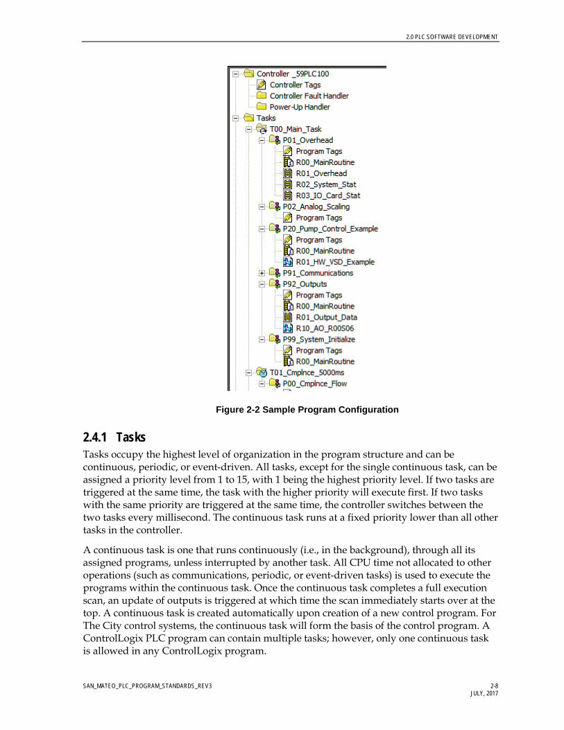
2.0 PLC SOFTWARE DEVELOPMENT
SAN_MATEO_PLC_PROGRAM_STANDARDS_REV3 2-8 JULY, 2017
Figure 2-2 Sample Program Configuration
2.4.1 Tasks Tasks occupy the highest level of organization in the program structure and can be continuous, periodic, or event-driven. All tasks, except for the single continuous task, can be assigned a priority level from 1 to 15, with 1 being the highest priority level. If two tasks are triggered at the same time, the task with the higher priority will execute first. If two tasks with the same priority are triggered at the same time, the controller switches between the two tasks every millisecond. The continuous task runs at a fixed priority lower than all other tasks in the controller.
A continuous task is one that runs continuously (i.e., in the background), through all its assigned programs, unless interrupted by another task. All CPU time not allocated to other operations (such as communications, periodic, or event-driven tasks) is used to execute the programs within the continuous task. Once the continuous task completes a full execution scan, an update of outputs is triggered at which time the scan immediately starts over at the top. A continuous task is created automatically upon creation of a new control program. For The City control systems, the continuous task will form the basis of the control program. A ControlLogix PLC program can contain multiple tasks; however, only one continuous task is allowed in any ControlLogix program.

2.0 PLC SOFTWARE DEVELOPMENT
SAN_MATEO_PLC_PROGRAM_STANDARDS_REV3 2-9 JULY, 2017
Periodic tasks are designed to run at preset time intervals ranging from 0.1 milliseconds to 2,000,000 milliseconds. Periodic tasks perform a function according to a specific rate. When the end of a specified time period is reached, the task is triggered. When triggered, the task interrupts any lower priority task (continuous, periodic, or event-driven), and all programs assigned to the task are executed or scanned once, from top to bottom. After this single scan, an output update is triggered, and control is returned to the task that was interrupted at the point at which it was interrupted. Multiple periodic tasks may exist on a controller, where each task is configured to operate at independent rates.
An event-driven task is a task that performs a specific function when triggered by a specified event. When the event-driven task is triggered, it interrupts any lower priority tasks, executes one time, and returns control to the task that was interrupted at the point at which it was interrupted.
An event-driven task can be triggered by any of the following.
• Change of state of a digital input • A new sample of analog data • A consumed tag • An event instruction • Various motion control operations
2.4.2 Programs Within a task, and serving as the next layer down in the organization structure, is the program. Each program contains its own program-scoped tag database (local data table), a main executable routine, and optionally several subroutines. You can also specify an optional fault routine for each program. The program-specific fault routine is executed if the controller encounters an instruction-execution fault within any of the routines in the associated program.
To execute the routines within a program when a program is triggered, at least one routine must be configured as the main routine. This is done within the properties dialog box of the program configuration. For the City PLC programs, each program will include one routine with a common name of R00_MainRoutine. Each R00_MainRoutine routine will be configured as the main routine for that program. This routine will then be used to call all other routines within that program using the Jump to Subroutine (JSR) command. Parameters within the JSR command shall not be used for the City PLC programs.
2.4.3 Routines Routines are the base of the control structure and incorporate the actual program control code. Each program within a task is expected to include a number of routines to better organize the controls for equipment.
The RSLogix5000 programming environment includes the ability to program routines in one of four IEC-61131 standard languages, including ladder (LAD), function block (FB), sequential function chart (SFC), and structured text (ST). Due to the difficulties associated with troubleshooting structured text, this programming language should not be used for programming any the City systems except within AOIs. SFC finds use in machine control

2.0 PLC SOFTWARE DEVELOPMENT
SAN_MATEO_PLC_PROGRAM_STANDARDS_REV3 2-10 JULY, 2017
where a defined repetitive sequence is required. Therefore, the applicability of SFC is limited for a process-intensive application.
The two main programming languages to be utilized for the City control programs will be ladder and function block. Due to the operations available, discrete (or Boolean) logic is best served through the use of ladder code. Function block on the other hand, allows for a large section of code to be viewed simultaneously, leading to easier troubleshooting. An FB, as applied by Rockwell Software, serves as a data tag and hence utilizes more CPU memory than functions used in the ladder programming environment. Therefore, line for line, a routine programmed in ladder will use less memory space in the CPU than a routine programmed in FB. As a result, it may be advantageous (though not mandatory) to configure routines using the ladder programming language.

SAN_MATEO_PLC_PROGRAM_STANDARDS_REV3 3-1 AUGUST 2016
3.0 Tagging/Naming Conventions
3.1 PLC Naming Conventions The City requires that new PLC programming be coded using Rockwell Automation’s RSLogix 5000 software (CPR9). In the RSLogix 5000 programming environment, ControlLogix projects are broken down into tasks, programs, and routines. These software components and other specific subcomponents of the software need to have names applied, which uniquely identify them.
3.1.1 PLC File and Controller Names The RSLogix 5000 PLC file names and the ControlLogix controller names should be representative of the controller’s primary control function as well as include a reference to the site name. The following syntax should be used.
_ffPLCnnn
ff Facility Number nnn Control Panel Number
Example: _97PLC100
Refer to Design Standard 05 – Equipment and Instrument Identification Standards document for a listing of the tag numbering components.
3.1.2 PLC Hardware Names (Communication and IO modules) Communication and IO modules added to a PLC configuration require unique names. The names assigned to communications and IO modules should provide an indication of module type, rack location, and slot location. These names should align themselves with information associated with facility loop databases. For communication and IO modules, the following syntax should be used.
RxxSyy_AA
AA Module Type (DI, DO, AI, AO, EN, CN, DN, MB, SR) where DI = Discrete Input
DO = Discrete Output AI = Analog Input AO = Analog Output EN = Ethernet Communications CN = ControlNet Communications DN = DeviceNet Communications MB = Modbus Communications SR = Serial Communications HC = High Speed Counter PI = Pulse Input

3.0 TAGGING/NAMING CONVENTIONS
SAN_MATEO_PLC_PROGRAM_STANDARDS_REV3 3-2 JULY, 2017
Rxx Rack Number (00 – xx) Syy Slot Number (00 – 16)
Example 1: R03S06_DI; Discrete input module in rack 03, slot 06 Example 2: R00S01_EN; Ethernet communications module in rack 00, slot 01
3.1.3 ControlLogix Task Names Within a ControlLogix PLC program, only one continuous task can be configured. However, multiple periodic or event driven tasks can be added. Task names should be such that the task priority, function of the task, and the rate at which a task is called (periodic tasks only) is shown. The following syntax is to be used for task names.
Taa_bbbbbbbbbb_XXms
Taa Task Number aa – Task number: The lower the task number the higher the priority in the range 01 to 15. Task 00 is reserved for the continuous task and represents lowest priority task.
bbbbbbbbbb Task Descriptive Name (25 characters max) XXms Reserved for periodic tasks. XX indicates the task time interval in
milliseconds.
3.1.4 ControlLogix Program File Names The PLC program should be divided into logical program groups such that all control code for a given unit process is contained within a separate program. For each program, the following syntax should be used.
Paa_bbbbbbbbbb
aa Program execution order in the task bbbbbbbbbb Program Descriptive Name (25 characters max)
3.1.5 ControlLogix Routine Names Routines should be given a name representative of the logic they execute. Every program will contain one main routine used to call all other subroutines in that program utilizing a series of JSR instruction. The main routine will simply be called R00_MainRoutine. The subroutine name should contain a prefix that will allow the routines to be put in order to show how they are called from the main program. The following syntax should be used.
Raa_bbbbbbbbbb
aa Routine order of sequence when jumped to from the R00_MainRoutine
bbbbbbbbbb Routine Descriptive Name (25 characters max)

3.0 TAGGING/NAMING CONVENTIONS
SAN_MATEO_PLC_PROGRAM_STANDARDS_REV3 3-3 JULY, 2017
3.2 PLC Software Tagging Criteria 3.2.1 Tagging Overview The tagging scheme is designed to be as simple as possible and still provide adequate capability to uniquely identify each control system loop.
3.2.2 Tag Numbering Format The software tag number will be a sequence of alpha and numeric components. The base tag should use a format of:
_ffISAlllnn
Where a data type includes subcomponents (elements), the tag will automatically include the necessary element information and follow a format of:
_ffISAlllnn.aaaaaaaa
ff Facility Number (F) ISA ISA or related symbol defining equipment type lll Loop Number (LN) nn Unit Number (UN) aaaaaaaa Data Type Element (TA)
Example: _01PIT23456.PV
Refer to Design Standard 05 – Equipment and Instrument Identification Standards document for a listing of the tag numbering components. Additional components will be added to the Design Standard 05 – Equipment and Instrument Identification Standards as needed during detailed design.

SAN_MATEO_PLC_PROGRAM_STANDARDS_REV3 4-1 AUGUST 2016
4.0 User-Defined Elements
4.1 General The A-B ControlLogix V27 CPU includes two forms of user-definable elements. These functions provide the ability for the programmer to create UDT and AOI. Using both types of user-definable elements enables the programmer to create more efficiently organized programs with increased standardization.
4.1.1 User Data Type The UDT is a custom data type (similar to an integer or real data type) that is created by the programmer. A UDT will usually incorporate a collection of tags of various data types into a single defined entity. An element in a UDT can be assigned any data type currently available in the CPU including that of another UDT. Once created, a UDT is available as a data type option available when creating database tags. Therefore, when a new tag is created in the tag database, the new tag can be assigned a UDT data type in the same way that it would be assigned an integer or real data type. The newly created tag of data type UDT will include all the elements of the UDT, which will show up as elements of the base tag (Base_Tag.element).
A consideration when creating a new UDT is that the processor uses memory based on the order used within the definition of the structure. The next 2 examples show two structures that have the exact same members, but the 1st example does not group data members of the same type consecutively and the second example does. Example #1 uses 32 bytes (256 bits or 16 words) of memory and Example #2 uses only 20 bytes (160 bits or 10 words). In other words, example #2 uses 60% less memory than example #1 just because it is grouped properly in the UDT. It is also important to note that the processor sets aside memory to optimize communication with SCADA. This means that there is actually a double impact if the UDTs are not set up properly.
The exception to grouping data structures according to data type occurs when you need to set up a UDT to match a particular system variable from the PLC status file. In these cases the UDT should be setup to match the data format presented in the user manuals. Member names for these UDTs should match the examples in order to allow the easiest troubleshooting.
Structure Name: EXAMPLE1
NAME Data Type Description
BOOL1 BOOL 1st BOOL
INT1 INT 1st INTEGER
BOOL2 BOOL 2nd BOOL

4.0 USER-DEFINED ELEMENTS
SAN_MATEO_PLC_PROGRAM_STANDARDS_REV3 4-2 JULY, 2017
NAME Data Type Description
INT2 INT 2nd INTEGER
BOOL3 BOOL 3rd BOOL
TIMER TIMER Internal Timer
BOOL4 BOOL 4th BOOL
INT3 INT 3rd INTEGER
BOOL5 BOOL 5th BOOL
Figure 4-1 Sample Non-optimized UDT Configuration
Structure Name: EXAMPLE2
NAME Data Type Description
TIMER TIMER Internal Timer
BOOL1 BOOL 1st BOOL
BOOL2 BOOL 2nd BOOL
BOOL3 BOOL 3rd BOOL
BOOL4 BOOL 4th BOOL
BOOL5 BOOL 5th BOOL
INT1 INT 1st INTEGER
INT2 INT 2nd INTEGER
INT3 INT 3rd INTEGER
Figure 4-2 Sample Optimized UDT Configuration
User-defined data types, or structures, will be set up based on the Add On Instruction (reference next section for details) that is to be used and will encompass all of the SCADA interface points required for the template. Each member of the structure is referenced using an extension name. The structure is then assigned as a data type for a PLC tag. The program then references each member in the following format "TAG.NAME." where TAG is the PLC tag, or address, and NAME is the element within the user-defined data structure.
For the City of San Mateo projects, UDTs are created to serve one of two main purposes. A UDT can be created to fill a specific task such as reading the date and time from the CPU. A UDT can also be designed to work with specific equipment such as motor starters or field devices.
Data created to work with specific equipment types may be split into two UDTs. One UDT designed to handle all PLC internal data. The other equipment-specific UDT designed to provide an interface to the HMI. Separating UDT data into internal data and HMI data
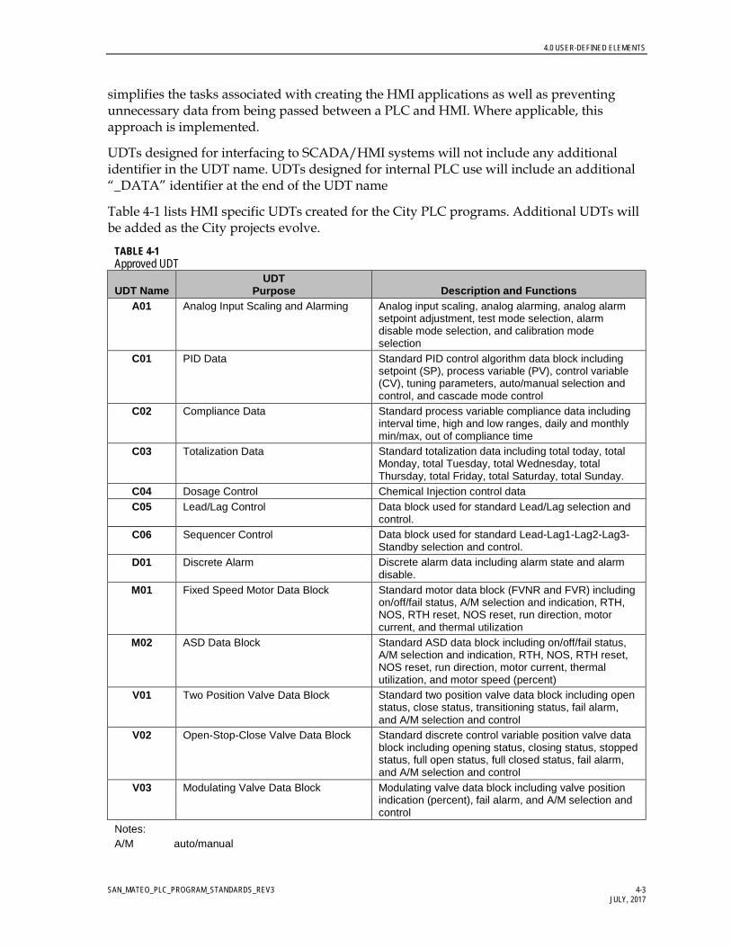
4.0 USER-DEFINED ELEMENTS
SAN_MATEO_PLC_PROGRAM_STANDARDS_REV3 4-3 JULY, 2017
simplifies the tasks associated with creating the HMI applications as well as preventing unnecessary data from being passed between a PLC and HMI. Where applicable, this approach is implemented.
UDTs designed for interfacing to SCADA/HMI systems will not include any additional identifier in the UDT name. UDTs designed for internal PLC use will include an additional “_DATA” identifier at the end of the UDT name
Table 4-1 lists HMI specific UDTs created for the City PLC programs. Additional UDTs will be added as the City projects evolve.
TABLE 4-1 Approved UDT
UDT Name UDT
Purpose Description and Functions A01 Analog Input Scaling and Alarming Analog input scaling, analog alarming, analog alarm
setpoint adjustment, test mode selection, alarm disable mode selection, and calibration mode selection
C01 PID Data Standard PID control algorithm data block including setpoint (SP), process variable (PV), control variable (CV), tuning parameters, auto/manual selection and control, and cascade mode control
C02 Compliance Data Standard process variable compliance data including interval time, high and low ranges, daily and monthly min/max, out of compliance time
C03 Totalization Data Standard totalization data including total today, total Monday, total Tuesday, total Wednesday, total Thursday, total Friday, total Saturday, total Sunday.
C04 Dosage Control Chemical Injection control data C05 Lead/Lag Control Data block used for standard Lead/Lag selection and
control. C06 Sequencer Control Data block used for standard Lead-Lag1-Lag2-Lag3-
Standby selection and control. D01 Discrete Alarm Discrete alarm data including alarm state and alarm
disable. M01 Fixed Speed Motor Data Block Standard motor data block (FVNR and FVR) including
on/off/fail status, A/M selection and indication, RTH, NOS, RTH reset, NOS reset, run direction, motor current, and thermal utilization
M02 ASD Data Block Standard ASD data block including on/off/fail status, A/M selection and indication, RTH, NOS, RTH reset, NOS reset, run direction, motor current, thermal utilization, and motor speed (percent)
V01 Two Position Valve Data Block Standard two position valve data block including open status, close status, transitioning status, fail alarm, and A/M selection and control
V02 Open-Stop-Close Valve Data Block Standard discrete control variable position valve data block including opening status, closing status, stopped status, full open status, full closed status, fail alarm, and A/M selection and control
V03 Modulating Valve Data Block Modulating valve data block including valve position indication (percent), fail alarm, and A/M selection and control
Notes: A/M auto/manual

4.0 USER-DEFINED ELEMENTS
SAN_MATEO_PLC_PROGRAM_STANDARDS_REV3 4-4 JULY, 2017
TABLE 4-1 Approved UDT
UDT Name UDT
Purpose Description and Functions CV control variable ft3/minute cubic feet per minute FVNR full-voltage nonreversing FVR full-voltage reversing g/sec grams per second mgd million gallons per day NOS number of starts (Cycles) PV process variable RTH run time hours SP setpoint ASD adjustable-speed drive
Figure 4-3 shows sample tag _97LIT00200. The tag is configured with a data type of A01 (analog input). As shown, the tag includes a number of elements which are a mix of real and Boolean data types. Every tag that is assigned a data type of A01 will include the same set of tag elements.
Figure 4-3 Sample Tag
4.2 Add-On Instructions The AOI is a custom-designed control element created by the programmer to incorporate PLC code designed for a specific task. The AOI is then applied, as a standard programming element, during PLC programming. AOIs are best applied to programming tasks requiring repetitive standardized code such as analog input scaling or analog alarm generation.
For the City PLC programs, an AOI can be created using ladder or FB. Once created, an AOI becomes a standard programming element accessed during PLC code creation in the same manner as other programming elements such as timers/counters or computational

4.0 USER-DEFINED ELEMENTS
SAN_MATEO_PLC_PROGRAM_STANDARDS_REV3 4-5 JULY, 2017
elements. As indicated in Figure 4-4, Access to Add-On Instructions, AOIs are accessed from the Add-On tab during programming.
Figure 4-4 Access to Add-On Instructions
The programmers shall use the Rockwell Automation generated AOIs for the City of San Mateo PLC programs. Additional AOIs will be added as the City’s projects evolve. For detailed description of a particular AOI, refer to the Rockwell Automation Guidelines.

SAN_MATEO_PLC_PROGRAM_STANDARDS_REV3 5-1 AUGUST 2016
5.0 PLC Program Documentation
All control programs created for the City need to include a minimum level of documentation integrated into the control code. This documentation is required to allow others, besides the original programmer, to understand the operation and functionality of the control code. This documentation is critical during the commissioning process and for future maintenance requirements.
Program documentation needs to describe individual control routines, to describe individual data tags, and to track changes to control code for maintenance purposes.
5.1 Routine Documentation Sufficient documentation within each routine should be included to adequately describe the functionality for each section of code, how the section of code works, and what variables affect the logic.
For a routine programmed using ladder, the first rung in the ladder file should use the No operation Command (NOP) instruction with a description of the purpose of the routine. Additional NOP rungs should be added, where appropriate, to separate the ladder routine into logical blocks, with each NOP rung providing a description of the purpose of the given section of code. Finally, individual rungs of PLC code should be documented, where required, to clarify complex code such as lengthy calculations, jump routines, or index-addressed code.
Figure 5-1 shows a sample ladder routine with typical documentation.
Figure 5-1 Sample Ladder Routine
For routines programmed in the FB language, the text box will serve the same purpose as the documented NOP rung in ladder routines. For an FB routine, one text box should provide a description of the routines purpose. Additional text boxes should then be added, where appropriate, to clarify sections of code.

5.0 PLC PROGRAM DOCUMENTATION
SAN_MATEO_PLC_PROGRAM_STANDARDS_REV3 5-2 JULY, 2017
Figure 5-2 shows a sample FB routine with a general block description.
Figure 5-2. Sample Function Block Routine
5.2 Tag Descriptions Every data tag utilized in control code should include a description outlining the purpose of the data. This description is in addition to the tag name. To allow for standardization across all programs, all programmers working on the City’s programs should configure their software to limit tag descriptions to a width of 13 characters. Where at all possible, tag descriptions should be limited to four lines. Helpful tag description information includes the purpose of the tag (control or status), associated equipment, equipment numbers, engineering units, or applicable ranges. For discrete tags, additional useful information includes the function of the tag in the 0 and/or 1 state.
The intent is to provide additional useful information beyond the tag name to allow for easy understanding of the tag’s purpose. As with data tags, the shorthand list of symbol components can be used to efficiently provide important information for tag descriptions.
The listing for approved symbols allowed in the City’s programs are presented in the document Design Standard 05 – Equipment and Instrument Identification Standards.
Figure 5-4 shows sample tag descriptions and tag names.

5.0 PLC PROGRAM DOCUMENTATION
SAN_MATEO_PLC_PROGRAM_STANDARDS_REV3 5-3 JULY, 2017
Figure 5-4 Sample Tag Descriptions and Tag Names

SAN_MATEO_PLC_PROGRAM_STANDARDS_REV3 6-1 AUGUST 2016
6.0 PLC Program Development
One key objective for PLC program development is to provide a program structure that is easy for O&M staff to understand and troubleshoot. A PLC program is built once and then adapted to changing operational needs for years. Defining PLC programming standards will make the PLC programs easier to understand and will reduce operating costs for the City of San Mateo, allowing for a more sustainable system.
Creation of a new control program requires a basic understanding of the control system requirements and selected hardware. The ControlLogix CPU part number and firmware version should be known at the outset of program creation. With this information and a preliminary IO layout, a new control program can be started.
Once a new program has been started, the steps required to program a fully functioning control program include:
• Create add-on elements (UDT and AOIs) − Import from standards files
• Add IO configuration (IO racks, IO modules, etc.) • Create preliminary tag database for field devices • Configure basic program structure (tasks and programs) • Add standard routines (Overhead, System Monitoring, etc.)
− Import from standards files • Add recurring code using UDTs and AOIs
− Analog Scaling − Analog Alarms
• Add detail control code • Add initialization, fault handling, and power-up routines
All RSLogix5000-based programs will be configured based on the common standards listed below. A standard template/example PLC program file shall be provided by the City of San Mateo, containing all necessary elements, including but not limited to the following: AOI’s, UDT’s, program structure and standard logic used in all PLCs.
6.1 General This section lists standards to be implemented in the creation or modification of any the City’s facility PLC programs. • All control code that is to be continuously scanned through the main continuous task
(T00_Main_Task) will be separated into logical programs within the main task. − Programs will be based on unit processes

6.0 PLC PROGRAM DEVELOPMENT
SAN_MATEO_PLC_PROGRAM_STANDARDS_REV3 6-2 JULY, 2017
• Each program within a task will include one main routine that will be used to call all other routines within a program. − No control code other than routine calls (JSR) will be included in a main routine. − All main routines will be named R00_MainRoutine
• Routines can be programmed in IEC 61131 compliant ladder, FB, or SFC. − Structured text will not be allowed unless specific approval is granted by the City of
San Mateo. − Function Block routines will use a D sheet size (22 by 34 inches) set to landscape
mode. • An overhead routine (to be included in the overhead program within the main task) is to
be included. This routine is used to provide standard code not affiliated with any specific process area and which may be used throughout the remainder of the PLC program. Such code may include (but is not limited to): − continuous timers for general program use − PID control timer(s) − Provide a daily roll over bit
o Roll over time used to trigger the roll over bit must be adjustable while the CPU is in run mode without the need to perform online edits.
• All programs will include an initialization routine. − This routine is separate from any power-up or fault handling routines. − This routine will be used to set hard-coded and default setpoints as well as to
initialize or reset sequence controls. − Activation of initialization routines will be from manually toggled bits. No
automatic initialization should be included to prevent accidental overwriting of existing configurations.
− All initialization routines will be named R99_Initialize • A control system monitoring routine is to be included in the overhead project. This
routine will include PLC code which will: − Read the time and date from the CPU − Retrieve the CPU run/remote/program status − Retrieve the CPU key switch position − Retrieve the maximum and last scan times − Retrieve the major and minor fault bits − Retrieve the fault status from applicable IO cards controlled by the CPU
• All PLC to PLC communications will be configured using Produced/Consumed tag arrays.
6.2 Tags and Data This section lists standards to be implemented in the creation or modification of tags or data for any the City’s PLC programs.

6.0 PLC PROGRAM DEVELOPMENT
SAN_MATEO_PLC_PROGRAM_STANDARDS_REV3 6-3 JULY, 2017
• Tag descriptions will be included for all data tags used in PLC control code.
− The control program tags and descriptions will be configured per Sections 4 and 5 of this document as well as the Design Standard 05 (Equipment and Instrumentation Guide).
• Separate tags will be configured for status and control functions to/from all HMI units.
− Where possible, UDTs dedicated to HMI data should be used.
• Boolean data type is not allowed for base tags.
− A minimum of one double-integer array should be created to allow for the use of Boolean tags in the PLC program.
− Actual tags used in the control program will be aliased to bits within the double integer array as required.
• Integer data types are not allowed for base tags
− A minimum of one integer array should be created to allow for the use of Integer tags in the PLC program.
− Array size will be in multiples of 2 registers (for example, array size 2, 4, 6, 8).
− Actual integer tags used in the control program will be aliased to the integer array as required.
• Single-integer data types are not allowed for base tags.
− Where necessary, one single-integer array will be created to allow for the use of integer tags in the PLC program.
− Array size will be in multiples of 4 registers (for example, array size 4, 8, 12, 16).
− Actual single-integer tags used in the control program will be aliased to the single-integer array, as required.
• Indexed addressing is not allowed for equipment control.
− Indexed addressing may be utilized for noncritical functions such as data transfer to/from the HMI if approved by the City of San Mateo.
− In cases where indexed addressing is used, sufficient documentation must be included in the program to clearly describe the functioning of the code and all addressing associated with the code.
• UDTs are allowed.
− A library of approved UDTs will be provided as part of the City’s standard sample PLC program.
− Additional UDTs can be used if approved by the City prior to implementation.
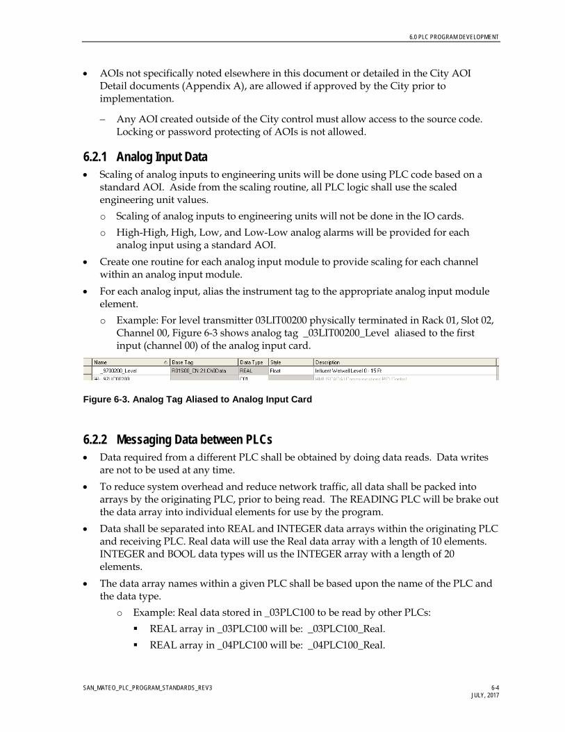
6.0 PLC PROGRAM DEVELOPMENT
SAN_MATEO_PLC_PROGRAM_STANDARDS_REV3 6-4 JULY, 2017
• AOIs not specifically noted elsewhere in this document or detailed in the City AOI Detail documents (Appendix A), are allowed if approved by the City prior to implementation.
− Any AOI created outside of the City control must allow access to the source code. Locking or password protecting of AOIs is not allowed.
6.2.1 Analog Input Data • Scaling of analog inputs to engineering units will be done using PLC code based on a
standard AOI. Aside from the scaling routine, all PLC logic shall use the scaled engineering unit values. o Scaling of analog inputs to engineering units will not be done in the IO cards. o High-High, High, Low, and Low-Low analog alarms will be provided for each
analog input using a standard AOI. • Create one routine for each analog input module to provide scaling for each channel
within an analog input module. • For each analog input, alias the instrument tag to the appropriate analog input module
element. o Example: For level transmitter 03LIT00200 physically terminated in Rack 01, Slot 02,
Channel 00, Figure 6-3 shows analog tag _03LIT00200_Level aliased to the first input (channel 00) of the analog input card.
Figure 6-3. Analog Tag Aliased to Analog Input Card
6.2.2 Messaging Data between PLCs • Data required from a different PLC shall be obtained by doing data reads. Data writes
are not to be used at any time. • To reduce system overhead and reduce network traffic, all data shall be packed into
arrays by the originating PLC, prior to being read. The READING PLC will be brake out the data array into individual elements for use by the program.
• Data shall be separated into REAL and INTEGER data arrays within the originating PLC and receiving PLC. Real data will use the Real data array with a length of 10 elements. INTEGER and BOOL data types will us the INTEGER array with a length of 20 elements.
• The data array names within a given PLC shall be based upon the name of the PLC and the data type.
o Example: Real data stored in _03PLC100 to be read by other PLCs: REAL array in _03PLC100 will be: _03PLC100_Real. REAL array in _04PLC100 will be: _04PLC100_Real.

6.0 PLC PROGRAM DEVELOPMENT
SAN_MATEO_PLC_PROGRAM_STANDARDS_REV3 6-5 JULY, 2017
• For BOOL data types, individual tags are mapped to bits within an INT word, which is part of the integer data array. This reduces the number of words required for communications. Within the integer data array a variable number of integers, located at the end of the array, will be dedicated to BOOL data. It is desirable to limit BOOL data as much as possible to limit unused bits in the system.
o Example: Transfer of BOOL elements from _03PLC100 _03PM00101.Remote – Pump 1 Local Remote Hand Switch _03PMP00101.Failed – Pump 1 Fault Status _03PMP00101.Running – Pump 1 running status _03PMP00102.Remote – Pump 2 Local Remote Hand Switch _03PMP00102.Failed – Pump 2 Fault Status _03PMP00102.Running – Pump 2 running status
o The BOOLs in _03PLC100 can be mapped into INT elements as follows: _03PM00101.Remote – _03PLC100_Int[0].0 _03PMP00101.Failed – _03PLC100_Int[0].1 _03PMP00101.Running – _03PLC100_Int[0].2 _03PM00102.Remote – _03PLC100 PLC_Int[1].0 _03PMP00102.Failed – _03PLC100 PLC_Int[1].1 _03PMP00102.Running – _03PLC100_PLC_Int[1].2
Refer to Appendix D for a listing of all Message Data mappings.
6.2.3 Standard Program Structure All ControlLogix programs shall be based on the tasks, programs, and routines structure indicated below.
• Main Task (continuous – T00_Main_Task) o Overhead Program (P01_Overhead) Main Routine (R00_MainRoutine) Overhead Routine (R01_Overhead) Control System Monitoring Routine (R02_System_Stat) I/O module Status Monitoring Routine (R03_IO_Card_Monitoring) DeviceNet Network Monitoring Routine (R03_DNET_Stat)
o Input Data Map Program (P02_Input_Scaling) Main Routine (R00_MainRoutine) Analog Scaling Routine 1 (R10_AI_Card1) Analog Scaling Routine 2 (R11_AI_Card2) Analog Scaling Routine 3 (R12_AI_Card3)
o Unit Process 1 Code Program (P10_UnitAreaName) Main Routine (R00_MainRoutine) Routine 1 Sub-process 1 controls (R01_SubProcessName) Routine 2 Sub-process 2 controls (R02_SubProcessName)

6.0 PLC PROGRAM DEVELOPMENT
SAN_MATEO_PLC_PROGRAM_STANDARDS_REV3 6-6 JULY, 2017
Routine 3 Sub-process 3 controls (R03_SubProcessName) Program Initialization Routine (R99_Initialize)
o Unit Process 2 Code Program (P11_UnitAreaName) Main Routine (R00_MainRoutine) Routine 1 Sub-process 1 controls (R01_SubProcessName) Routine 2 Sub-process 2 controls (R02_SubProcessName) Routine 3 Sub-process 3 controls (R03_SubProcessName)
o Communications Program (P91_Communications) Main Routine (R00_MainRoutine) Communications 1 Routine (PLC_x/PLC_a messages) (R01_PLCa) Communications 2 Routine (PLC_x/PLC_b messages) (R02_PLCb) Communications 3 Routine (Other communications such as Modbus or Serial
if required) o Initialization Program (P99_System_Initialize) Main Routine (R00_MainRoutine)
• Periodic Task 1 (T01_Cmplnce_5000ms) o Compliance (P02_Cmplnce) Main Routine (R00_MainRoutine) Compliance control code (R01_Compliance)
o PIDs (P10_UnitAreaName) Main Routine (R00_MainRoutine) Compliance control code (R01_process_PID)
• Periodic Task 2 (Txx_description_xxMS; where applicable) • Event Task 1 (Txx_description; where applicable) • Event Task 2 (Txx_description; where applicable) • Etc. • Unscheduled Programs/Phases
o Revision Control Program Revision Document 1 Revision Document 2
o Temporary Ladder Routine For Code Development o Temporary Function Block Routine For Code Development

SAN_MATEO_PLC_PROGRAM_STANDARDS_REV3 7-1 AUGUST 2016
7.0 PLC Programming Best Practices
When creating a PLC program, there are numerous paths to the same result. There is no right or wrong way to program a PLC. Only what works and what does not. As such, some specific practices result in a better developed PLC program, with “better” being a relative term and having numerous shades of grey. This section sets out to document various “Best Practices” which should be used when developing PLC programs for the City of San Mateo.
7.1 Simplify Rungs of Code For ladder routines, avoid long complicated rungs of code (Figure 7-1).
• Break up a complicated rung of code into smaller parts. • Avoid excessive branching in a single rung of code. • Use a single rung comment at the beginning of the group to explain what you are doing
(Figure 7-2).
Avoid this… Figure 7-1 Complicated Rungs of Ladder Code

7.0 PLC PROGRAMMING BEST PRACTICES
SAN_MATEO_PLC_PROGRAM_STANDARDS_REV3 7-2 July 2016
Try using this instead… Figure 7-2 Simplified Rungs of Ladder Code
7.2 Data Types Use a data type appropriate for the information being manipulated.
• The RSLogix5000 software is configured to select a default data type (usually DINT). • Maintain consistency throughout the PLC program for given functions keeping in mind:
− DINT Range: -2147483648 to 2147483647 − INT Range: -32768 to 32767 − SINT Range: -127 to 128
7.3 Prefacing Conditions When prefacing an output with test or condition, apply a test or condition to each line.
• Do not rely on a default condition on the first branch with conditional test on the second branch.
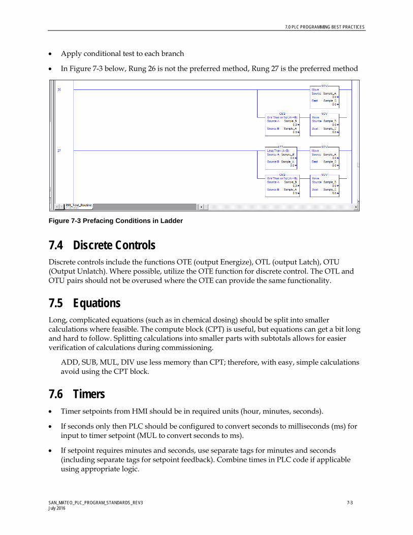
7.0 PLC PROGRAMMING BEST PRACTICES
SAN_MATEO_PLC_PROGRAM_STANDARDS_REV3 7-3 July 2016
• Apply conditional test to each branch
• In Figure 7-3 below, Rung 26 is not the preferred method, Rung 27 is the preferred method
Figure 7-3 Prefacing Conditions in Ladder
7.4 Discrete Controls Discrete controls include the functions OTE (output Energize), OTL (output Latch), OTU (Output Unlatch). Where possible, utilize the OTE function for discrete control. The OTL and OTU pairs should not be overused where the OTE can provide the same functionality.
7.5 Equations Long, complicated equations (such as in chemical dosing) should be split into smaller calculations where feasible. The compute block (CPT) is useful, but equations can get a bit long and hard to follow. Splitting calculations into smaller parts with subtotals allows for easier verification of calculations during commissioning.
ADD, SUB, MUL, DIV use less memory than CPT; therefore, with easy, simple calculations avoid using the CPT block.
7.6 Timers • Timer setpoints from HMI should be in required units (hour, minutes, seconds).
• If seconds only then PLC should be configured to convert seconds to milliseconds (ms) for input to timer setpoint (MUL to convert seconds to ms).
• If setpoint requires minutes and seconds, use separate tags for minutes and seconds (including separate tags for setpoint feedback). Combine times in PLC code if applicable using appropriate logic.

7.0 PLC PROGRAMMING BEST PRACTICES
SAN_MATEO_PLC_PROGRAM_STANDARDS_REV3 7-4 July 2016
o For example, if hours and minutes are required for the setpoint inputs, the programmer can convert hours to minutes then add the minutes setpoint to provide total time setpoint.
• Where called for, include countdown logic to provide an indication of the time remaining to the activation of specified function.
− Time remaining should utilize same format as time setpoint including separate tags for hours or minutes as required.
7.7 Counters Counters can be done in different ways. One option is to use a counter block (CTU or CTD) (Figure 7-5). Another is to use an ADD block (Figure 7-6).
• CTU/CTD provides additional status information. • ADD uses less memory. • No preferred method. Just be consistent within a section of code (routine or program).
Figure 7-5 Counter Using CTU

7.0 PLC PROGRAMMING BEST PRACTICES
SAN_MATEO_PLC_PROGRAM_STANDARDS_REV3 7-5 July 2016
Figure 7-6 Counter Using ADD
7.8 Button Control A two-state toggle control method using single command bit with feedback, shown in Figure 7-7.
• Can be used for auto/manual selection and feedback • Is not applicable to PanelView Plus, as buttons do not include a set value function • Provides for positive control confirmation:
− If control from SCADA configured to use momentary command, it is possible for the PLC to miss the command. This logic eliminates this possibility.
• Requires button action on SCADA using Set Tag to 1 type action • Separates status feedback for use in PLC code and for status display on SCADA.
Figure 7-7 Two-State Toggle Control

7.0 PLC PROGRAMMING BEST PRACTICES
SAN_MATEO_PLC_PROGRAM_STANDARDS_REV3 7-6 July 2016
7.9 Sequence Control Sequence control is any group of control actions in which the result of one action (step) initiates an adjacent action (step + 1), normally applied to sequences of more than two steps.
• Sequence Indication and Control
− For every sequence-controlled operation, the PLC should be configured to include a sequence reset button in case a sequence hangs up.
− For every sequence controller, PLC should include a sequence fail alarm indication.
− For every sequence controller, PLC should include a sequence step indication. o Step indication of data type SINT or INT o Do not use data type real for sequence step indication
7.10 PID Control • PIDs configured to use independent tuning parameters
• PIDs are not to be programmed within process control routines under the main continuous task and but rather as separate periodic tasks
7.11 SCADA Set points PLC should be configured to verify that set point is within allowable range (see sample code in Figure 7-8).
• If set point is greater than maximum allowable, move max to set point • If set point is less than minimum allowable, move min to set point • Finally, move se tpoint to required location
Use a separate feedback tag for set point inputs. Indicate on HMI.

7.0 PLC PROGRAMMING BEST PRACTICES
SAN_MATEO_PLC_PROGRAM_STANDARDS_REV3 7-7 July 2016
Figure 7-8 Sample SCADA Setpoints
7.12 Alarming Whenever possible, alarms should be interlocked to reduce the number of cascading alarms. For example, a motor high temperature alarm will cause the motor to stop running, but should not create a motor fail alarm. These cascading alarms can lead to overwhelming the HMI with alarms because of a single failure. For example, a power failure generates an alarm at the HMI. But, when the power fails, all of the motors will stop running, causing many alarms to be sent to the HMI.
This can be achieved using different techniques. One technique (using relay ladder logic) is to add a normally closed (XIO) relay contact from the High Temperature alarm in series with the motor fail alarm coil. See Figure 7-9 for a sample.
Figure 7-9 Sample Alarm Cascading Interlock

SAN_MATEO_PLC_PROGRAM_STANDARDS_REV3 8-1 July 2016
8.0 Glossary
AOI Add-On Instruction – Reusable PLC programming instruction, created by the programmer, to provide specific control functions or features
Back Plane Interfaced used to pass data into and out of modules. The backplane can be physical (ControlLogix IO rack) or virtual (CompactLogix, which does not include a separate IO rack)
Base Rack IO rack containing a PLC. May or may not include IO modules
CPR Coordinated Product Release – Term used by Rockwell Software to define a suite of software and hardware firmware levels tested by Rockwell Software and certified to work together. For the City control system projects all software used and hardware firmware will be CPR9 compliant.
CTD down counter
CTU up counter
Event Instruction The EVENT instruction is used to trigger one execution of an event task.
Event Task A task that performs a specific function when triggered by a specified event. When the event task is triggered, it interrupts any lower priority tasks, executes one time, and returns control to the task that was interrupted, at the point at which it was interrupted.
human-machine interface
An open architecture operator interface that is configured using object technology
Input/Output External signals interfaced to the PLC control system. Can be hard wired or networked from physical devices (transmitters, motors, etc) or software applications (HMI, Historian Data Collector, Etc)
IO Module Input or Output module, installed within an IO Rack, used to provide a hardwired interface to field devices such as transmitters or motors
IO Rack For modular-based PLC control system, the IO Rack is the base structure used to house the various modules making up the PLC control system
8.0 GLOSSARY
SAN_MATEO_PLC_PROGRAM_STANDARDS_REV3 8-2 July 2016
programmable logic controller
A modular microprocessor-based hardware device designed to monitor field device control signals, evaluate programmed logic based on field device signals, and provide appropriate output signals to control equipment for facility operation.
Remote IO IO modules contained within a remote rack
Remote Rack IO rack not containing a PLC, but which interfaces to a PLC via a network connection
UDT User Data Type created by the programmer containing single or multiple data elements of various types.

SAN_MATEO_PLC_PROGRAM_STANDARDS_REV3 8-1 July 2016

SAN_MATEO_PLC_PROGRAM_STANDARDS_REV3 8-1 July 2016

SAN_MATEO_PLC_PROGRAM_STANDARDS_REV3 July, 2016