
CITY OF LA PINE, OREGON 2016 STANDARDS AND ... Design Standards Page i CITY OF LA PINE, OREGON 2016...
33
2016 Design Standards Page i CITY OF LA PINE, OREGON 2016 STANDARDS AND SPECIFICATIONS DESIGN STANDARDS GENERAL ........................................................................................................................... 1 I. DESIGN PARAMETERS ................................................................................................... 1 II. A. STREET ........................................................................................................................... 1 1. General ............................................................................................................................. 1 2. Utility Access Roads and Fire Access Roads................................................................... 2 3. Slope ................................................................................................................................. 2 4. Sight Distance .................................................................................................................. 3 5. Vertical Curves ................................................................................................................. 3 6. Horizontal Curves ............................................................................................................ 4 7. Road Crown...................................................................................................................... 7 8. Access Spacing Guidelines .............................................................................................. 7 9. Curbs Radius .................................................................................................................... 7 10. Curbs............................................................................................................................. 7 11. Sidewalks ...................................................................................................................... 8 12. Accessibility ................................................................................................................. 8 13. Concrete (Portland Cement Concrete (PCC)) .............................................................. 8 14. Street Signs ................................................................................................................... 9 15. Cluster Postal Delivery Boxes ...................................................................................... 9
Transcript of CITY OF LA PINE, OREGON 2016 STANDARDS AND ... Design Standards Page i CITY OF LA PINE, OREGON 2016...

2016 Design Standards Page i
CITY OF LA PINE, OREGON
2016 STANDARDS AND SPECIFICATIONS
DESIGN STANDARDS
GENERAL ........................................................................................................................... 1 I.
DESIGN PARAMETERS ................................................................................................... 1 II.
A. STREET ........................................................................................................................... 1
1. General ............................................................................................................................. 1
2. Utility Access Roads and Fire Access Roads................................................................... 2
3. Slope ................................................................................................................................. 2
4. Sight Distance .................................................................................................................. 3
5. Vertical Curves ................................................................................................................. 3
6. Horizontal Curves ............................................................................................................ 4
7. Road Crown...................................................................................................................... 7
8. Access Spacing Guidelines .............................................................................................. 7
9. Curbs Radius .................................................................................................................... 7
10. Curbs ............................................................................................................................. 7
11. Sidewalks ...................................................................................................................... 8
12. Accessibility ................................................................................................................. 8
13. Concrete (Portland Cement Concrete (PCC)) .............................................................. 8
14. Street Signs ................................................................................................................... 9
15. Cluster Postal Delivery Boxes ...................................................................................... 9
2016 Design Standards Page ii
16. Street Lights ................................................................................................................ 10
17. Pavement Section ....................................................................................................... 10
18. Dead End Streets and Alleys ...................................................................................... 11
19. Pavement Taper .......................................................................................................... 11
20. Cut and Fill Slope Construction ................................................................................. 12
B. STORMWATER ............................................................................................................ 13
1. General ........................................................................................................................... 13
2. Storm Sewer Design ....................................................................................................... 13
C. SEWER .......................................................................................................................... 14
1. General ........................................................................................................................... 14
2. Septic Tanks and Inlet Piping......................................................................................... 14
3. Sewer Main .................................................................................................................... 15
4. Sulfide Control ............................................................................................................... 18
5. Sewer Services ............................................................................................................... 18
6. Sanitary Sewer Manholes ............................................................................................... 19
7. Cleanouts ........................................................................................................................ 19
8. Access to Sewer Facilities .............................................................................................. 19
9. Sampling Manholes ........................................................................................................ 19
D. WATER .......................................................................................................................... 20
1. Main Line ....................................................................................................................... 20
2. Meters ............................................................................................................................. 21
3. Fire Hydrants .................................................................................................................. 21
E. UTILITIES ......................................................................................................................... 23
1. Prohibition on Cutting Recently Constructed Streets..................................................... 23
2. Utility Conduit................................................................................................................ 23
3. Shared Trenches ............................................................................................................. 23
4. Private Utilities in Public Rights-of-Way ...................................................................... 23
5. Trench Patching in Paved Right-of-way Areas .............................................................. 23
6. Trench Backfill ............................................................................................................... 24
F. IRRIGATION .................................................................................................................... 25
1. General ........................................................................................................................... 25
2016 Design Standards Page iii
DRAWINGS ...................................................................................................................... 26 III.
A. SUBMITTAL ................................................................................................................. 26
B. PLAN SCALE AND SIZE ............................................................................................. 26
C. INFORMATION REQUIRED ON PLANS .................................................................. 26
1. General ........................................................................................................................... 26
2. Streets ............................................................................................................................. 28
3. Stormwater – See Chapter 3 Central Oregon Stormwater Manual ................................ 28
4. Sanitary Sewer................................................................................................................ 29
5. Water .............................................................................................................................. 29
6. Construction Cost Estimate and Fees ............................................................................. 30
2016 Design Standards Page 1
GENERAL I.
These are the minimum design standards for the City of La Pine. The following standards shall be
adhered to unless an exception is granted in writing by the City Engineer. Exceptions will be granted
based upon a design that is the functional equivalent of the design parameters listed herein. Street
standards are generally in conformance with the “American Association of State Highway and
Transportation Officials (AASHTO) Geometric Design of Highways and Streets” 2011 Edition. This
document is referred to as AASHTO throughout these standards.
NOTE: Many of the existing streets in the City of La Pine are under the jurisdiction of Deschutes
County. In addition to City requirements, streets under the jurisdiction of Deschutes County
require separate approvals and permits from the Deschutes County Road Department prior to
construction. Contact the City for questions regarding the jurisdiction of specific streets.
DESIGN PARAMETERS II.
A. STREET
1. General
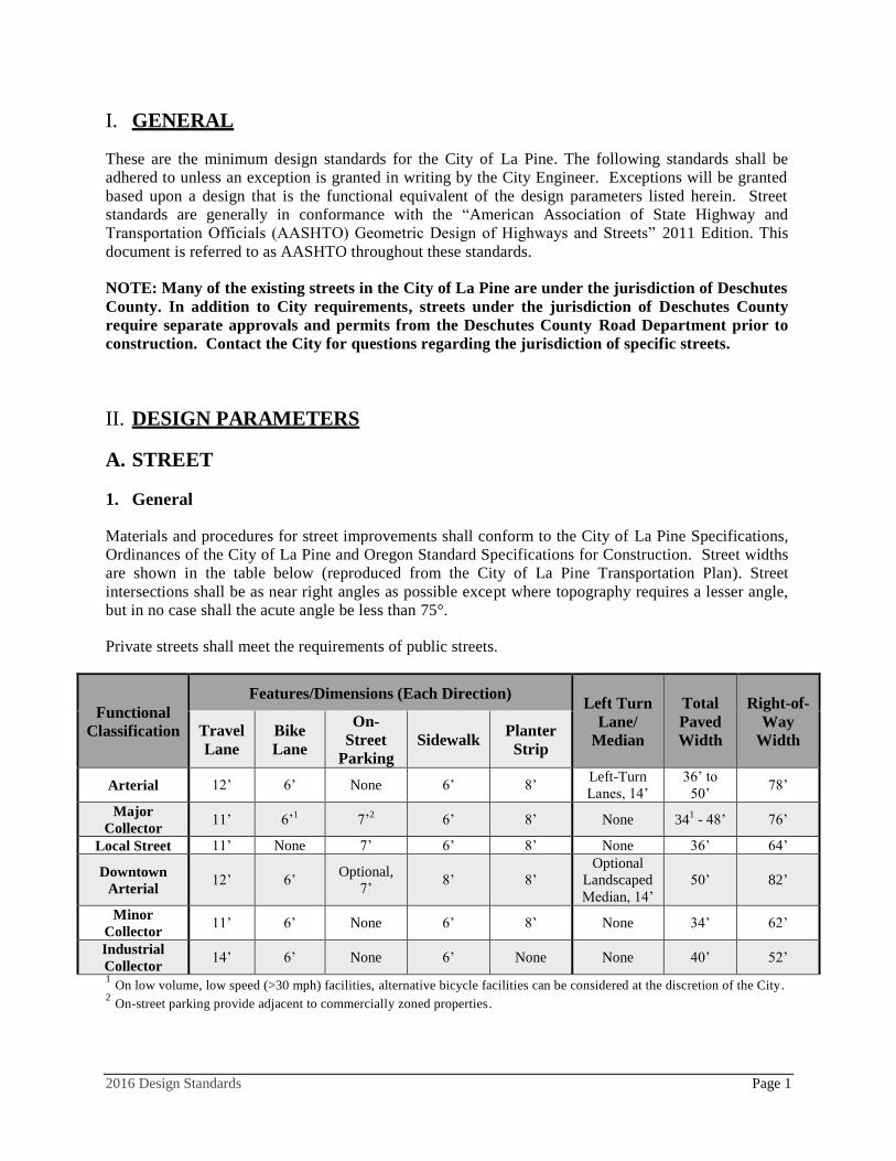
Materials and procedures for street improvements shall conform to the City of La Pine Specifications,
Ordinances of the City of La Pine and Oregon Standard Specifications for Construction. Street widths
are shown in the table below (reproduced from the City of La Pine Transportation Plan). Street
intersections shall be as near right angles as possible except where topography requires a lesser angle,
but in no case shall the acute angle be less than 75°.
Private streets shall meet the requirements of public streets.
Functional
Classification
Features/Dimensions (Each Direction) Left Turn
Lane/
Median
Total
Paved
Width
Right-of-
Way
Width Travel
Lane
Bike
Lane
On-
Street
Parking
Sidewalk Planter
Strip
Arterial 12’ 6’ None 6’ 8’ Left-Turn
Lanes, 14’
36’ to
50’ 78’
Major
Collector 11’ 6’
1 7’
2 6’ 8’ None 34
1 - 48’ 76’
Local Street 11’ None 7’ 6’ 8’ None 36’ 64’
Downtown
Arterial 12’ 6’
Optional,
7’ 8’ 8’
Optional
Landscaped
Median, 14’
50’ 82’
Minor
Collector 11’ 6’ None 6’ 8’ None 34’ 62’
Industrial
Collector 14’ 6’ None 6’ None None 40’ 52’
1 On low volume, low speed (>30 mph) facilities, alternative bicycle facilities can be considered at the discretion of the City.
2 On-street parking provide adjacent to commercially zoned properties.
2016 Design Standards Page 2
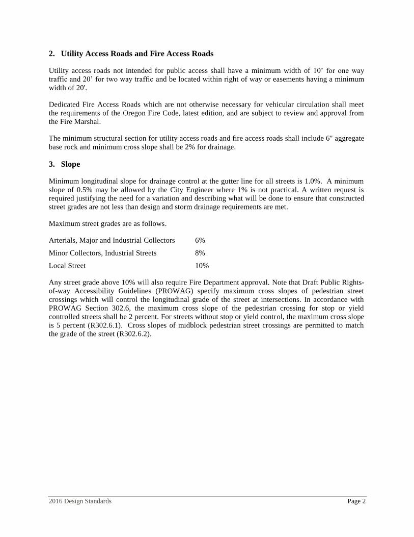
2. Utility Access Roads and Fire Access Roads
Utility access roads not intended for public access shall have a minimum width of 10’ for one way
traffic and 20’ for two way traffic and be located within right of way or easements having a minimum
width of 20'.
Dedicated Fire Access Roads which are not otherwise necessary for vehicular circulation shall meet
the requirements of the Oregon Fire Code, latest edition, and are subject to review and approval from
the Fire Marshal.
The minimum structural section for utility access roads and fire access roads shall include 6" aggregate
base rock and minimum cross slope shall be 2% for drainage.
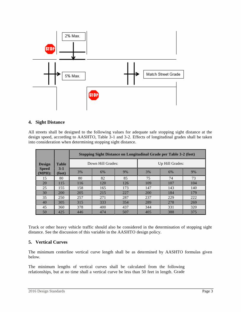
3. Slope
Minimum longitudinal slope for drainage control at the gutter line for all streets is 1.0%. A minimum
slope of 0.5% may be allowed by the City Engineer where 1% is not practical. A written request is
required justifying the need for a variation and describing what will be done to ensure that constructed
street grades are not less than design and storm drainage requirements are met.
Maximum street grades are as follows.
Arterials, Major and Industrial Collectors 6%
Minor Collectors, Industrial Streets 8%
Local Street 10%
Any street grade above 10% will also require Fire Department approval. Note that Draft Public Rights-
of-way Accessibility Guidelines (PROWAG) specify maximum cross slopes of pedestrian street
crossings which will control the longitudinal grade of the street at intersections. In accordance with
PROWAG Section 302.6, the maximum cross slope of the pedestrian crossing for stop or yield
controlled streets shall be 2 percent. For streets without stop or yield control, the maximum cross slope
is 5 percent (R302.6.1). Cross slopes of midblock pedestrian street crossings are permitted to match
the grade of the street (R302.6.2).
2016 Design Standards Page 3
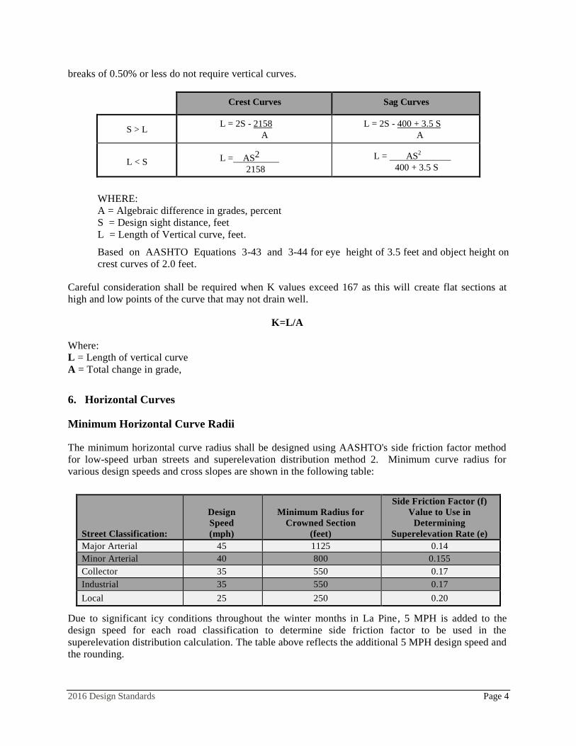
4. Sight Distance
All streets shall be designed to the following values for adequate safe stopping sight distance at the
design speed, according to AASHTO, Table 3-1 and 3-2. Effects of longitudinal grades shall be taken
into consideration when determining stopping sight distance.
Truck or other heavy vehicle traffic should also be considered in the determination of stopping sight
distance. See the discussion of this variable in the AASHTO design policy.
5. Vertical Curves
The minimum centerline vertical curve length shall be as determined by AASHTO formulas given
below.
The minimum lengths of vertical curves shall be calculated from the following
relationships, but at no time shall a vertical curve be less than 50 feet in length. Grade
Design
Speed
(MPH):
Table
3-1
(feet)
Stopping Sight Distance on Longitudinal Grade per Table 3-2 (feet)
Down Hill Grades: Up Hill Grades:
3% 6% 9% 3% 6% 9%
15 80 80 82 85 75 74 73
20 115 116 120 126 109 107 104
25 155 158 165 173 147 143 140
30 200 205 215 227 200 184 179
35 250 257 271 287 237 229 222
40 305 315 333 354 289 278 269
45 360 378 400 437 344 331 320
50 425 446 474 507 405 388 375
2016 Design Standards Page 4
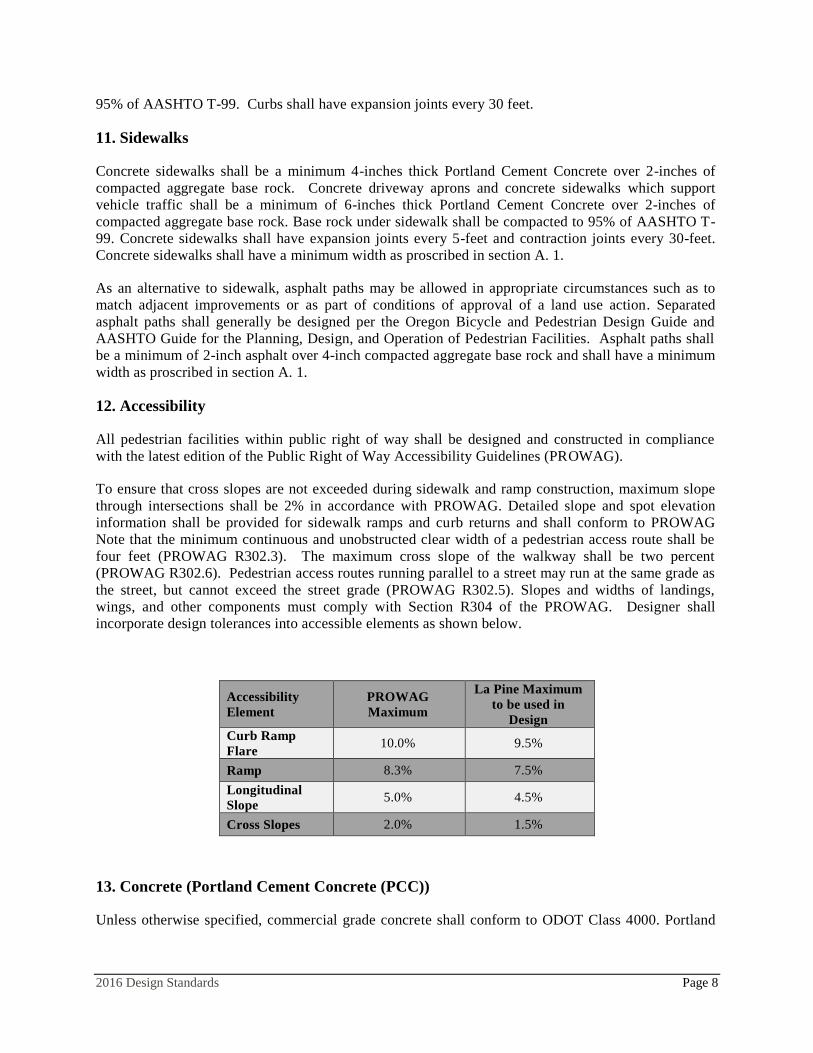
breaks of 0.50% or less do not require vertical curves.
Crest Curves Sag Curves
S > L L = 2S - 2158
A
L = 2S - 400 + 3.5 S
A
L < S L = AS2
2158
L = AS2
400 + 3.5 S
WHERE:
A = Algebraic difference in grades, percent
S = Design sight distance, feet
L = Length of Vertical curve, feet.
Based on AASHTO Equations 3-43 and 3-44 for eye height of 3.5 feet and object height on
crest curves of 2.0 feet.
Careful consideration shall be required when K values exceed 167 as this will create flat sections at
high and low points of the curve that may not drain well.
K=L/A
Where:
L = Length of vertical curve
A = Total change in grade,
6. Horizontal Curves
Minimum Horizontal Curve Radii
The minimum horizontal curve radius shall be designed using AASHTO's side friction factor method
for low-speed urban streets and superelevation distribution method 2. Minimum curve radius for
various design speeds and cross slopes are shown in the following table:
Street Classification:
Design
Speed
(mph)
Minimum Radius for
Crowned Section
(feet)
Side Friction Factor (f)
Value to Use in
Determining
Superelevation Rate (e)
Major Arterial 45 1125 0.14
Minor Arterial 40 800 0.155
Collector 35 550 0.17
Industrial 35 550 0.17
Local 25 250 0.20
Due to significant icy conditions throughout the winter months in La Pine, 5 MPH is added to the
design speed for each road classification to determine side friction factor to be used in the
superelevation distribution calculation. The table above reflects the additional 5 MPH design speed and
the rounding.

2016 Design Standards Page 5
Horizontal Sight Distance
The insides of curves can present obstructions in a driver’s ability to see objects in their driving path.
Required stopping sight distances (from the Stopping Sight Distance table above) shall be obtained for
all horizontal curve design using the following methodology.
Considering the graphic below, use the following geometric relations to determine proper horizontal
setbacks from driver’s eye to the obstruction.
M = R(1-cos(28.65S/R)) and S = Rcos-1
(1-M/R)/28.65
Where:
M = mid-ordinate shown as “HSO” in the graphic below
S = Stopping Sight Distance (Chord)
R = Radius of the arc lying along the centerline of the travel lane
The Line of Sight (Chord) must be equal to or greater than the value shown in the Stopping Sight
Distance shown above.
Superelevation Rate
Superelevation is to be used only as a design element to enhance drivability of horizontal curves on
arterial and collector streets. The use of superelevation for any purpose will require the approval of the
City Engineer and will be decided on a case by case basis. Design superelevation rates for local streets

2016 Design Standards Page 6
will not exceed 4%. The maximum design superelevation for collectors and arterials shall generally be
6%. Minimum superelevation for any classification shall be 2%. Plans incorporating superelevation
shall show either left and right roadway elevations or superelevation diagrams on the profile.
Superelevation rates (e) will be determined using the following equation.
e = V2/15R – f
Where:
e is the superelevation rate.
V is the design speed.
R is the radius of the curve.
f is the side friction factor obtained from the above table.
Superelevation Transition, Runoff, and Tangent Runout
The designer must be concerned with three profiles in the development of a superelevated section: left
roadway, centerline and right roadway. Superelevation shall be obtained by rotating two of these
profiles around the third stable profile (referred to as the axis of rotation and is usually the centerline)
which reflects the overall design.
The superelevation transition section consists of the superelevation runoff and tangent runout
(sometimes referred to as crown runout) sections. The superelevation runoff section consists of the
length of roadway needed to accomplish a change in outside-lane cross slope from zero (flat) to full
superelevation, or vice versa. The tangent runout section consists of the length of roadway needed to
accomplish a change in outside-lane cross slope from the normal cross slope rate to zero (flat), or vice
versa. To limit lateral acceleration, the pavement rotation in the superelevation transition section should
be achieved over a length that is sufficient to make such rotation imperceptible to drivers. To be
pleasing in appearance, the pavement edges should not appear distorted to the driver.
In confined situations (e.g. reversing curves, intersections in close proximity, etc.), shorter superelevation
transitions may be used with the approval of the City Engineer. In no case shall the change in cross slope
exceed 6% per station.
One-fourth (1/4th) of the runoff section may be placed within the horizontal curve. No transition
section shall be less than 100' in length. The minimum transition section lengths shall be determined
in accordance with the AASHTO Policy on Geometric Design of Highways and Streets 2011 Edition,
Chapter 3 Transition Design Controls. AASHTO Table 3-17b provides runoff length for various
design speeds, number of lanes and superelevation rates. Superelevated roadways where longitudinal
grade is flat (less than 1%) present particular drainage problems within superelevation runoff /
transition portions of the curve or approach / departure sections. Superelevation of roadways where
longitudinal grade is flat will require approval of the City Engineer.
Additionally, concentrated drainage flows crossing the roadway will not be permitted under any
circumstances. Therefore, these concentrated flows will be intercepted / diverted / disposed of in the
location of the beginning of the superelevation transition for both approach and departure ends of the
curve and in both directions of travel.
Reverse Curves
On all streets having a design speed of greater than 30 mph there shall be a minimum 100' tangent
section between reverse horizontal curves.

2016 Design Standards Page 7
7. Road Crown
Collector and arterial streets shall be designed with either a crowned or a superelevated section through
curves. A shed section on collector and arterial streets is not acceptable. On other classes of streets
with design speeds less than 30 mph, shed sections are permissible. Shed section cross slope shall not
be greater than 2%. Cross slopes less than 2% require approval of the City Engineer. Where a non-
standard street width is designed, the crown shall be based on a 2% cross slope.
8. Access Spacing Guidelines
The following outlines the access spacing guidelines within La Pine. These guidelines pertain to public
and private access. When parcels are abutted by multiple roadways, access should be provided from
the lowest order facility, where feasible.
Access points on local streets shall be a minimum of ten feet (10’) apart as measured from
edge of driveway to edge of driveway.
Access points on Collector Streets shall be a minimum of one hundred feet (100’) apart as
measured from centerline of access to centerline of access.
Access points on Arterial Streets shall be a minimum of three hundred feet (300’) apart as
measured from centerline of access to centerline of access.
9. Curbs Radius
The minimum curb radius shall be as follows:
Arterial - Arterial 35'
Local-Local 15'
Local-Collector 20'
Local-Arterial 25'
Collector-Collector 25'
Collector-Arterial 35'
Industrial - Any 35' *
*(35' radius with parking eliminated within 40' of intersection measured from curb
return)
When evaluating curb return radius, designers should consider the location of sidewalk ramps and
attempt to line up crosswalks with sidewalks to maintain a straight walking path across intersections.
A reduced curb radius may be allowed in areas with high pedestrian traffic to improve crosswalk
alignment and visibility. Curb radii less than the standard shown herein must be approved by the City
Engineer.
Street striping shall be designed in accordance with the current ODOT Traffic Line Manual.
10. Curbs
Concrete curbs shall be a minimum 12-inches in height, 6-inches wide at the top and 8-inches wide at
the base. Curb face exposure shall be 6-inches. On streets with a design speed of 35mph or higher,
curbs shall be 16-inches in height, 6-inches wide at the top, 9-inches wide at the base, and curb face
exposure shall be 7-inches. Base rock under curb shall be a minimum of 2-inches thick, compacted to
2016 Design Standards Page 8
95% of AASHTO T-99. Curbs shall have expansion joints every 30 feet.
11. Sidewalks
Concrete sidewalks shall be a minimum 4-inches thick Portland Cement Concrete over 2-inches of
compacted aggregate base rock. Concrete driveway aprons and concrete sidewalks which support
vehicle traffic shall be a minimum of 6-inches thick Portland Cement Concrete over 2-inches of
compacted aggregate base rock. Base rock under sidewalk shall be compacted to 95% of AASHTO T-
99. Concrete sidewalks shall have expansion joints every 5-feet and contraction joints every 30-feet.
Concrete sidewalks shall have a minimum width as proscribed in section A. 1.
As an alternative to sidewalk, asphalt paths may be allowed in appropriate circumstances such as to
match adjacent improvements or as part of conditions of approval of a land use action. Separated
asphalt paths shall generally be designed per the Oregon Bicycle and Pedestrian Design Guide and
AASHTO Guide for the Planning, Design, and Operation of Pedestrian Facilities. Asphalt paths shall
be a minimum of 2-inch asphalt over 4-inch compacted aggregate base rock and shall have a minimum
width as proscribed in section A. 1.
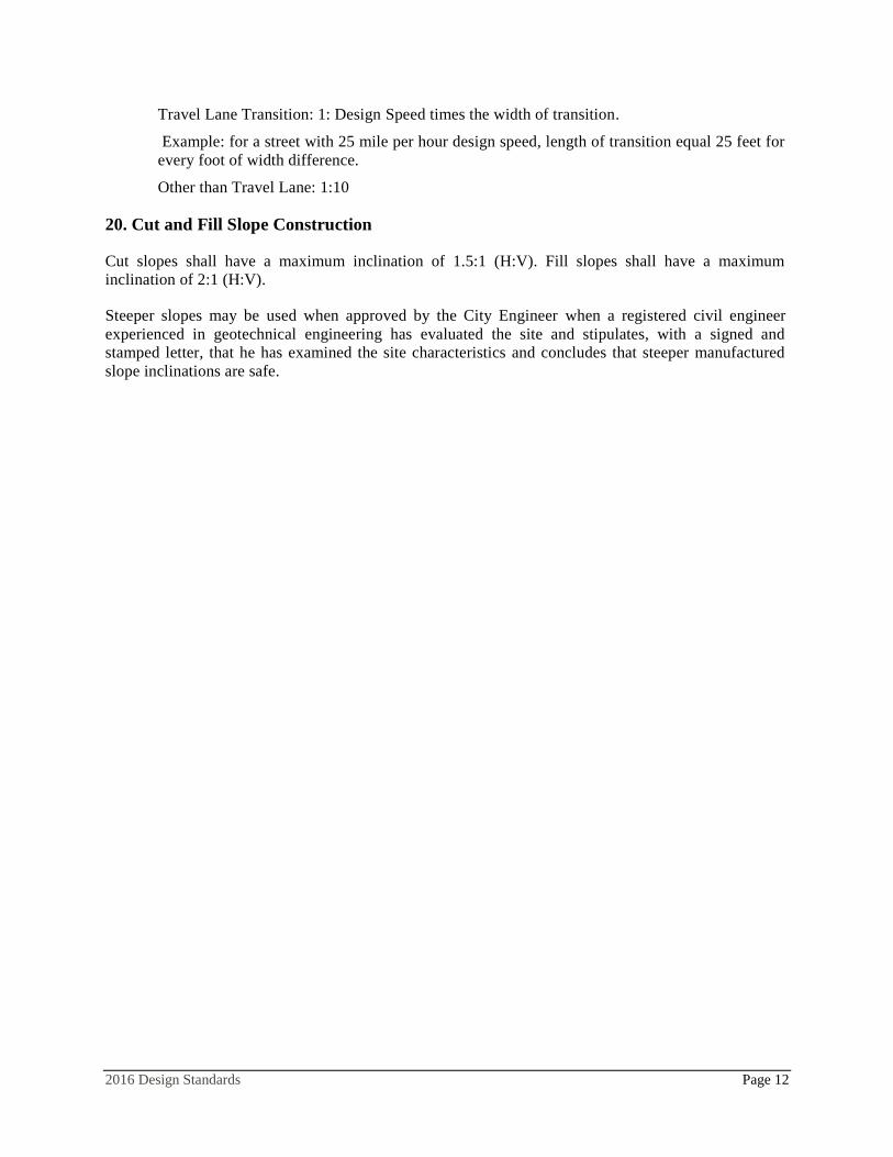
12. Accessibility
All pedestrian facilities within public right of way shall be designed and constructed in compliance
with the latest edition of the Public Right of Way Accessibility Guidelines (PROWAG).
To ensure that cross slopes are not exceeded during sidewalk and ramp construction, maximum slope
through intersections shall be 2% in accordance with PROWAG. Detailed slope and spot elevation
information shall be provided for sidewalk ramps and curb returns and shall conform to PROWAG
Note that the minimum continuous and unobstructed clear width of a pedestrian access route shall be
four feet (PROWAG R302.3). The maximum cross slope of the walkway shall be two percent
(PROWAG R302.6). Pedestrian access routes running parallel to a street may run at the same grade as
the street, but cannot exceed the street grade (PROWAG R302.5). Slopes and widths of landings,
wings, and other components must comply with Section R304 of the PROWAG. Designer shall
incorporate design tolerances into accessible elements as shown below.
Accessibility
Element
PROWAG
Maximum
La Pine Maximum
to be used in
Design
Curb Ramp
Flare 10.0% 9.5%
Ramp 8.3% 7.5%
Longitudinal
Slope 5.0% 4.5%
Cross Slopes 2.0% 1.5%
13. Concrete (Portland Cement Concrete (PCC))
Unless otherwise specified, commercial grade concrete shall conform to ODOT Class 4000. Portland

2016 Design Standards Page 9
Cement shall be Type I or Type II. Concrete shall contain no additives that cause rapid setting. Air
entrainment of 4% - 7% is required.
Weather Limitations
Concrete shall be placed when the air temperature in the work zone is at least 35°F. Concrete shall not
be placed on frozen ground. Concrete work shall be protected from freezing for seven days after
placement blankets or other insulation methods will be used to protect the concrete for a minimum of
seven days and recording thermometers will be used to verify the concrete surface temperature does
not fall below 32°F. Any concrete indicated as being damaged from freezing shall be rejected and
replaced.
The Inspector can require the Contractor to provide a minimum recording thermometer, having not less
than 2° divisions, to verify that the temperature at the surface of the work does not fall below 32°F.
The reading shall be taken as close to the surface of the concrete as possible.
Curing
Concrete shall be cured by application of a liquid membrane forming compound applied uniformly to
the damp concrete by pressure spray methods, or by keeping the concrete protected by covering and
moist for a minimum of 72 hours. Curing compounds shall conform to the requirements of AASHTO
M 148. All compounds shall be Class A. Solvent based compounds shall be Type 1-D.
Concrete curbs shall be allowed to cure for a minimum of 72 hours before starting spreading and
compaction operations for aggregate base against or within 2 feet of new curbs. Curbs cracked,
chipped or damaged by equipment operations shall be removed and replaced prior to paving. Curbs
shall be replaced in sections by sawcutting at the nearest expansion joints.
Finishing
Concrete shall be finished to a smooth and uniform texture by troweling and floating. The surface shall
have a light broomed finish transverse to the direction of traffic, unless otherwise specified.
14. Street Signs
Street signage must conform to the latest edition of the Manual on Uniform Traffic Control Devices.
The Contractor shall verify the correctness of all street sign legends and names immediately prior to
installation.
15. Cluster Postal Delivery Boxes
Cluster box locations shall be shown on the plans. US Postal Service must agree on location and type
of delivery boxes. Cluster Postal Delivery Boxes should be constructed on residential streets in an area
that minimizes impact on abutting properties.
Cluster mailboxes shall meet accessibility requirements in the Americans with Disabilities Act (ADA)
and PROWAG.
a) Provide a 72-inch wide concrete pad adjacent to cluster mailboxes with turning space that
conforms to Section 304 of the 2010 ADA Standards for Accessible Design.

2016 Design Standards Page 10
b) Provide a pedestrian access route to adjacent sidewalk complying with PROWAG Section
R301.
c) Provide a pedestrian access route to on street parking complying with PROWAG Section R301
within 25 feet of the mailbox.
Cluster Postal Delivery Boxes desired along arterial or collector streets should be constructed off
public right-of-way on common ground dedicated to that purpose and provided with appropriate
driveway access. Cluster Postal Delivery Boxes shall not be constructed on arterial street right-of-way.
Cluster Postal Delivery Boxes may be constructed on collector street right-of-way provided that a
turnout meeting the following requirements is constructed.
a) The center of the turnout shall be located in the center of a tangent section of the Collector.
This tangent section shall have a length of not less than two times the stopping sight distance
for the design speed.
b) The required right-of-way width shall be increased to provide for the parking bay.
c) The bay shall not be located less than the design stopping sight distance from any intersection.
d) The bay of the turnout shall be a minimum of 40' in length and not less than 10' in depth.
e) Tapered approach sections into the bay shall be not less than 10:1.
f) Curb radius in the bay shall be not less than 50' radius.
g) There shall be adequate stopping sight distance on either end of the turnouts into the parking
bay.
h) The bay shall be signed with the following:
10 Minute Parking
No U-turns (MUTCD # R3-4a or R3-4 with R3-4p)
16. Street Lights
Street lights shall be shown on the plans and provided at the following locations:
Intersections
Cul-de-sac if over 200 feet from the intersection
Mid-block for blocks longer than 400 feet from center of intersection to center of intersection
High-use driveways and other locations designated by the City Engineer.
Poles and fixtures shall conform to the power provider standards.
Standard Mid State Electric head fixtures shall be used except that in downtown areas the City may
require decorative poles and lights to match adjacent improvements, or as indicated in conditions of
approval of a land use action.
17. Pavement Section
Roadway shall be asphalt concrete (AC) with state spec ¾”- base rock. The pavement sections shall be
as follows.

2016 Design Standards Page 11
Street Classification: AC (Lift)
(inches) Binder
Base Rock
(inches)
Subgrade
Compaction
Major Arterial
5 (3/2)
Level 3, 1\2” dense
graded
PG 70-28 (top)
PG 64-28 (bottom)
12 90%
Minor Arterial
5 (3/2)
Level 3, 1\2” dense
graded
PG 70-28 (both lifts)
12 90%
Collector
4 (2/2)
Level 3, 1\2” dense
graded
PG 64-28 (both lifts)
10 90%
Industrial
4 (2/2)
Level 3, 1\2” dense
graded
PG 64-28 (both lifts)
12 90%
Local
3 (1 lift)
Level 2, 1\2” dense
graded
PG 64-28 8 90%
All Classifications Compact to 92% Compact to
100% 90%
Asphaltic Concrete Pavement
Asphaltic Concrete Pavement (ACP) shall be designed and constructed in accordance with ODOT
Standard Specifications section 00744.
Weather Limitations
Asphalt concrete shall not be placed during rain, snow, or other adverse weather conditions. The
minimum surface temperature for paving is dependent on the thickness of the lift.
More than 2-inches – Minimum 40° F Surface Temperature
2-inches to 2.5-inchs – Minimum 50° F Surface Temperature
Less than 2-inches – Minimum 60° F Surface Temperature
18. Dead End Streets and Alleys
A turnaround must be provided on all dead end streets, alleys and all weather access roads. Through
alleys are encouraged, but where they cannot be provided and the alley is a required emergency access,
either a standard cul-de-sac or alternate turnaround meeting the requirements of the Oregon Fire Code
must be provided. Dead end alleys shall have a hammerhead turnaround per Oregon fire code.
19. Pavement Taper
When street transitions to a different pavement width, the edge of the pavement shall be tapered as
follows:
2016 Design Standards Page 12
Travel Lane Transition: 1: Design Speed times the width of transition.
Example: for a street with 25 mile per hour design speed, length of transition equal 25 feet for
every foot of width difference.
Other than Travel Lane: 1:10
20. Cut and Fill Slope Construction
Cut slopes shall have a maximum inclination of 1.5:1 (H:V). Fill slopes shall have a maximum
inclination of 2:1 (H:V).
Steeper slopes may be used when approved by the City Engineer when a registered civil engineer
experienced in geotechnical engineering has evaluated the site and stipulates, with a signed and
stamped letter, that he has examined the site characteristics and concludes that steeper manufactured
slope inclinations are safe.

2016 Design Standards Page 13
B. STORMWATER
1. General
Stormwater systems in the public right-of-way and private property shall be designed and tested in
accordance with the latest version of the Central Oregon Stormwater Manual. Roadside swales are
generally appropriate to treat and dissipate stormwater within right of way in La Pine, however, piped
storm sewer systems are also acceptable and may be necessary due to design constraints. Drywells are
not approvable within public right of way.
2. Storm Sewer Design
a. Storm sewers shall generally conform to the same specifications as sanitary sewers (see
Section II C).
b. Flanking inlets at sags will not be required provided that the primary inlet is shown to be
adequate to capture the design flow.
c. Double-sized catch basins are normally required for inlets. A single catch basin is acceptable
for the collection of water where special situations apply.
d. Curb inlet catch basins shall be installed in arterial and major collector streets to provide better
bicycle routes.
e. Inlets shall be provided at intersections of collectors and arterials. Inlets should be provided at
intersections of local streets. These inlets shall be so arranged that water is not directed
through the intersection or in certain cases, around a curb return.
f. Inlets should be provided to avoid ice formation on the roadway.
g. Valley gutter intersections may be allowed with approval of the City Engineer in situations
such as intersections of short cul-de-sacs with local streets.
h. Storm pipe shall meet one of the following requirements.
Depth Material Diameter Standard Comment
< 30” PVC < 18” AWWA C900 or C905
> 30” PVC < 18” ASTM D3034
> 30” PVC > = 18” ASTM F697
> 30” Polypropylene 12” to 30” ASTM F2736
Smooth interior, annular exterior
corrugations and bell and spigot
joints with gaskets
> 30” Polypropylene 30” to 60” ASTM F2764
Smooth interior, annular exterior
corrugations and bell and spigot
joints with gaskets
3. Trench Backfill
Trench backfill shall conform to Section 00405 of the Oregon Standard Specifications for
Construction, current edition.

2016 Design Standards Page 14
C. SEWER
The City of La Pine uses an effluent sewer collection system or septic tank effluent gravity (STEG)
system to collect sewage from residences and businesses. Septic tanks are required at every sewer
lateral to sewer main lines. Guidelines and Design Criteria were adopted from the DEQ Guidelines for
Design of Septic Tank Effluent Pump or Gravity (STEP/STEG) Sewer Projects Involving Common
Sewers.
1. General
Sewer/water line separation and construction is established by Oregon State Health Department
Standards. Materials and procedures for sewer facilities shall conform to Oregon D.E.Q. specifications
and APWA Standard Specifications.
Sewer facilities shall be installed in rights-of-way except in those situations where, in the
determination of the City Engineer, drainage basins cannot be served from the right-of-way. In those
cases, an easement will be required. All public sewer easements shall have a minimum width of 20
feet.
General Requirements are as Follows:
Standard Sewer System: A septic tank effluent gravity (STEG) system shall be used to collect
sewage from residence and businesses. Mainlines are effluent only, all solids shall be contained.
Septic tank effluent pressure (STEP) systems will be considered case-by-case.
Cleanouts: Cleanouts shall be installed on mainlines at a maximum of 400 foot intervals in the City of
La Pine STEG system, and shall be located at all pipe intersections and angle points. Manholes are not
typically utilized in the City of La Pine wastewater collection system.
Septic Tank: A septic tank is required at each developed property. Tank capacity shall be 1000 gallons
minimum, and shall be sized according to OAR 340-71-220(3). All new septic tanks, existing septic
tanks, or used septic tanks must pass a leakage test prior to use. The City maintains septic tanks within
city limits. The maintenance of septic tanks ends at the upstream wall of the septic tank. A
maintenance easement must be created outside of public right away around septic tanks. Sewer lines
upstream of the septic tanks are private and are not maintained by the City.
Construction Plans: Engineering firms submitting sewer plans shall include a sewer profile. The
profile will include the existing ground elevation, proposed street grade, existing utilities or other
underground apparatus, pipe diameter, material and slope, manhole locations, station and invert
elevations, horizontal and vertical scales, and trench backfill information. Plan views shall show all
horizontal control required to build the sewer, streets, property lines and right-of-way, all planimetrics,
utilities, north arrow and scale.
2. Septic Tanks and Inlet Piping
Single tanks serving multiple lots under separate ownership will not be allowed. Each property
shall have a separate septic tank and sewer lateral.
Systems serving facilities such as RV parks, mobile home parks, apartments, and unit
developments are usually under the control of a single customer or responsible association. At

2016 Design Standards Page 15
the discretion of the engineer, such systems may be designed with shared tanks, subject to
requirements of the Oregon State Plumbing Code.
Tanks shall be sized according to flow per criteria published in OAR 340-71-220(3). Minimum
tank capacity shall be 1000 gallons.
Construction details and configuration of tanks shall generally conform to OAR 340-73-050,
Dosing Tank Construction. All tanks shall feature inlet and outlet risers with lockable covers.
Covers shall be designed for H-20 loading in traffic areas. Inlet riser shall be minimum 24"
diameter. Outlet risers shall be sized to accommodate and access the equipment installed, with
24" diameter as a minimum. Intermediate 24" risers will be required on large tanks over 3000
gallons.
Tanks shall be designed for all anticipated structural loads, including soil backfill. Where
vehicle access is allowed, the tank shall be protected with an appropriate structural slab and
steel covers for the tank risers. All designs shall be stamped per OAR 34-052.
To assure retention of solids and grease in the tank, all tanks shall feature a plastic effluent
screen. Screens shall conform to the standard published in OAR 340-73-056. No unscreened
discharges will be allowed.
Flotation of tanks in areas of high groundwater shall be anticipated in system design. Structural
design features and operational procedures shall be employed to prevent flotation.
Existing tanks which fully meet the requirements, including leakage test, may be considered
for use in the STEG system case-by-case.
Pipe connections to tanks shall be made with an approved commercial water stop manufactured
for the intended purpose. Field improvised water stops or adapters will not be approved.
All sewage from the building including kitchen, laundry, and bath wastes shall be intercepted
and conveyed to the STEG tank. No grey water systems will be allowed.
Septic tanks shall be tested hydrostatically after installation and after all pipe penetrations have
been completed.
For leakage testing, tanks shall be filled to a marked point 2" above the base of the risers.
Leakage shall not exceed 1 gallon in 24 hours.
3. Sewer Main
a. Design Parameters
a. Location: Sewer mains should be located in accordance with the Department of
Environmental Quality and OAR Chapter 340, Division 52. Sewer mains shall be located on
roadway centerline on tangent sections and as close as practicable to this configuration on
curves. Gravity sewer mains from cleanout to cleanout shall run in a straight alignment.
b. Depth: Minimum cover for all standard sewer lines except sewer services shall be 36 inches.
c. Minimum Diameter: For gravity sewer, the minimum size shall be 6 inches. Size of
2016 Design Standards Page 16
pressure lines will be determined by the design engineer.
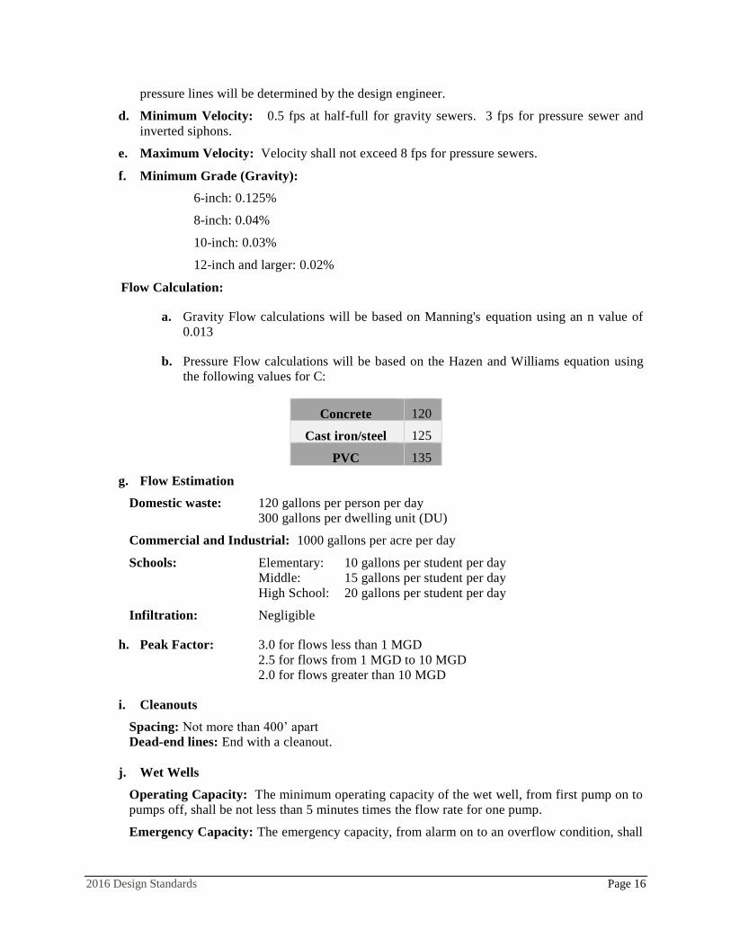
d. Minimum Velocity: 0.5 fps at half-full for gravity sewers. 3 fps for pressure sewer and
inverted siphons.
e. Maximum Velocity: Velocity shall not exceed 8 fps for pressure sewers.
f. Minimum Grade (Gravity):
6-inch: 0.125%
8-inch: 0.04%
10-inch: 0.03%
12-inch and larger: 0.02%
Flow Calculation:
a. Gravity Flow calculations will be based on Manning's equation using an n value of
0.013
b. Pressure Flow calculations will be based on the Hazen and Williams equation using
the following values for C:
Concrete 120
Cast iron/steel 125
PVC 135
g. Flow Estimation
Domestic waste: 120 gallons per person per day
300 gallons per dwelling unit (DU)
Commercial and Industrial: 1000 gallons per acre per day
Schools: Elementary: 10 gallons per student per day
Middle: 15 gallons per student per day
High School: 20 gallons per student per day
Infiltration: Negligible
h. Peak Factor: 3.0 for flows less than 1 MGD
2.5 for flows from 1 MGD to 10 MGD
2.0 for flows greater than 10 MGD
i. Cleanouts
Spacing: Not more than 400’ apart
Dead-end lines: End with a cleanout.
j. Wet Wells
Operating Capacity: The minimum operating capacity of the wet well, from first pump on to
pumps off, shall be not less than 5 minutes times the flow rate for one pump.
Emergency Capacity: The emergency capacity, from alarm on to an overflow condition, shall
2016 Design Standards Page 17
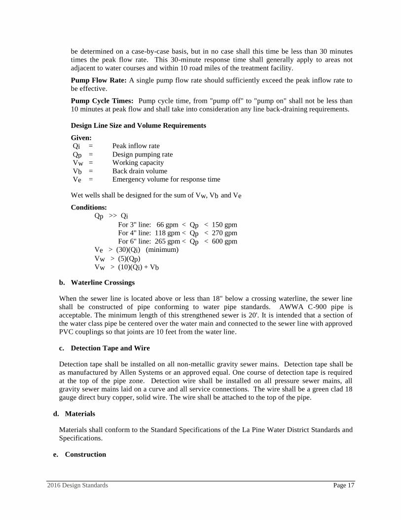
be determined on a case-by-case basis, but in no case shall this time be less than 30 minutes
times the peak flow rate. This 30-minute response time shall generally apply to areas not
adjacent to water courses and within 10 road miles of the treatment facility.
Pump Flow Rate: A single pump flow rate should sufficiently exceed the peak inflow rate to
be effective.
Pump Cycle Times: Pump cycle time, from "pump off" to "pump on" shall not be less than
10 minutes at peak flow and shall take into consideration any line back-draining requirements.
Design Line Size and Volume Requirements
Given:
Qi = Peak inflow rate
Qp = Design pumping rate
Vw = Working capacity
Vb = Back drain volume
Ve = Emergency volume for response time
Wet wells shall be designed for the sum of Vw, Vb and Ve
Conditions: Qp >> Qi
For 3" line: 66 gpm < Qp < 150 gpm
For 4" line: 118 gpm < Qp < 270 gpm
For 6" line: 265 gpm < Qp < 600 gpm
Ve > (30)(Qi) (minimum)
Vw > (5)(Qp) Vw > (10)(Qi) + Vb
b. Waterline Crossings
When the sewer line is located above or less than 18" below a crossing waterline, the sewer line
shall be constructed of pipe conforming to water pipe standards. AWWA C-900 pipe is
acceptable. The minimum length of this strengthened sewer is 20'. It is intended that a section of
the water class pipe be centered over the water main and connected to the sewer line with approved
PVC couplings so that joints are 10 feet from the water line.
c. Detection Tape and Wire
Detection tape shall be installed on all non-metallic gravity sewer mains. Detection tape shall be
as manufactured by Allen Systems or an approved equal. One course of detection tape is required
at the top of the pipe zone. Detection wire shall be installed on all pressure sewer mains, all
gravity sewer mains laid on a curve and all service connections. The wire shall be a green clad 18
gauge direct bury copper, solid wire. The wire shall be attached to the top of the pipe.
d. Materials
Materials shall conform to the Standard Specifications of the La Pine Water District Standards and
Specifications.
e. Construction

2016 Design Standards Page 18
Construction shall conform to the City of La Pine Standard Specifications and applicable Standard
Drawings. Prior to installing a sewer facility in an unimproved street, the street must be brought to
sub-grade to ensure that adequate bury, depth of cover, and utility separation is acquired. In the
event the street is to be improved at a later date, the street shall be properly staked to the approved
design prior to the commencement of sewer line construction.
4. Sulfide Control
Because of corrosion, odor, and safety concerns, STEG discharges into unarmored gravity sewers shall
not exceed 0.1 mg/l hydrogen sulfide content. To assure against sulfide formation in slow-moving
lines, sewers shall be sized to flow no more than half-full at average daily flow and to provide at least
0.5 fps velocity when flowing half-full.
STEP/STEG system designs shall include effective controls to prevent the development of
hydrogen sulfide in service lines, pressure sewers, and sections of small-diameter, gravity
sewers.
For sewer segments with minimum grade, minimum velocity, and potential to flow more than
half full, the City may require that downstream conventional sewer manholes and cleanouts
shall be armored with approved acid-proof coatings for a sufficient distance to dissipate the
hydrogen sulfide.
5. Sewer Services
All single family residential sewer service laterals shall be a minimum of four (4) inches in diameter
which shall be connected to a septic tank located outside of right-of-way. The slope of the pipe from
the septic tank to the main line shall be 1% or greater.
Each service line shall have a minimum of 30-inches of cover at the property or right-of-way line.
Each service line shall be vented at the upper end. Venting shall be continuous through the tank and
building stack.
All new duplex and multi-family service laterals shall be a minimum of six inches in diameter, except
when higher flows require a larger line size. However, existing 4-inch service laterals with clean out
may be used to serve duplex or multi-family lots with approval of City Engineer, unless flow rates are
greater than the capacity of the existing line.
Commercial and industrial service laterals shall be a minimum of six inches in diameter. However,
existing four (4)-inch service laterals with clean out may be used, with approval of the City Engineer.
Separate and independent building sewers shall be provided for buildings on separate lots or parcels.
Sewer services shall be extended at minimum grade or steeper as required to provide gravity service to
each building. Sewer services shall not have less than 30-inches of cover at the property line, and shall
be located as required to provide gravity service to each lot or parcel.
Pressure sewer services shall be designed by a competent professional. The pump curve with the
operating point indicated shall be submitted to the City Engineer or Public Works Manager so it may
be ascertained that the proposed installation will not conflict with the operation of the City system.
Pressure mains shall be a minimum of 3 inches in diameter and all check valves, gate valves will have
the capacity to pass a 3-inch ball. The service line shall be sized one size larger than the pump outlet.

2016 Design Standards Page 19
6. Sanitary Sewer Manholes
Manholes are not typically used on sewer mains in the City of La Pine and may only be substituted for
cleanouts when approved by the City Engineer and Public Works Manager.
7. Cleanouts
Cleanout spacing shall be 400’ maximum. Conventional open-channel manholes typically not be
allowed except where desired to site a flume for flow measurement. Cleanouts shall be sealed with a
screwed cap or plug secured under a tamperproof (bolt-down) cover.
Cleanouts shall be located as shown on the design plans or as directed by the City Engineer, or
representative, in a manner to provide complete accessibility and to minimize the possibility of damage
from vehicles or injury to pedestrians.
Location of the center of cleanouts in a vehicle wheel track is not acceptable. Location of the center of
cleanouts within 5 feet of the curb line is not acceptable. Location of cleanouts outside of paved areas
is not generally acceptable. If cleanouts cannot be located in the pavement, then a six-inch thick
concrete pad, 2.5 foot square centered on the cleanouts cover must be provided.
Changes in the direction of flow within sewer cleanouts shall be no more than 90º and shall be
accomplished with two (2) 45º fittings with the cleanout connected to the upstream fitting.
8. Access to Sewer Facilities
Where cleanouts lie outside of the paved roadway, an access road with dedicated right-of-way or
easement, shall be constructed to provide all weather access to the cleanout. This access road shall
meet all weather service road standards or be paved. Support facilities such as, but not limited, to
drainage structures, vehicular turnaround with 38 foot turning radius, or a pad-lockable gate may be
required on any cleanout location outside of the paved roadway.
9. Sampling Manholes
At the discretion of the City on a case-by-case basis, sanitary sewer sampling manholes may be
required for City effluent monitoring. Sampling manholes, when required, shall be constructed up-
gradient from any discharge into the public sewer system, and shall be accessible by City staff at all
times. The sampling manhole shall be constructed, owned and maintained by the property owner. The
manhole may be located at the sewer connection within public right-of-way. Privately owned
sampling manholes within public right-of-way are subject to revocable right-of-way approval. At the
option of the property owner, the sampling manhole may be located on private property within an
easement that provides unobstructed access to City personnel. If manholes cannot be located in the
pavement, then a six -inch thick concrete pad 5 foot square centered on the manhole cover must be
provided.
10. Trench Backfill
Trench backfill shall conform to Section 00405 of the Oregon Standard Specifications for
Construction, current edition.

2016 Design Standards Page 20
D. WATER
Materials and procedures for water facilities shall conform to the Standard Specifications of the City of
La Pine Standards and Specifications, Oregon Health Division Administrative Rules, and AWWA
standards. Water facilities shall be installed in public rights-of-way except in those situations where,
in the determination of the City Engineer, service areas and/or pressure levels will be better served by
an alternate design. In those cases, an easement will be required.
1. Main Line
a. Minimum Size and Depth
The minimum size for mainline shall be 8 inches except as otherwise indicated in the current City of
La Pine Water System Facilities Plan. Lines must be sized to provide the following required fire flows
per the most current version of the Oregon Fire Code and La Pine Rural Fire Protection District.
All main lines shall end with a fire hydrant for maintenance purposes. Hydrant lines may be 6" if total
length is less than 400 feet. Hydrant runs longer than 400 feet will require 8" line. A fire flow analysis
will be required to determine the size for lines longer than 400 feet. Minimum cover on all water lines
shall be 36”.
b. Required Information on Drawings
All drawings that include water and sewer mains submitted for review by the City Engineer shall have
the street station and offset, size, number, and type of fittings specified at the location they occur.
Specifying only the deflection angle of the line (e.g. 30°) is not acceptable.
c. Location
Water mains shall be located centerline with a minimum 10-foot horizontal separation from parallel
sewer lines. Separation from sewer lines shall be in accordance with OAR 333-61-0050.
d. Service Lines
A separate water service, including meter, shall be required for each lot of record. All water fittings,
boxes and meters are subject to City approval.
Service lines are to terminate in an approved meter box. Service lines shall be constructed, complete
and with all incidentals to the terminus of the meter box, to be located directly behind the sidewalk or,
if there is no sidewalk, directly behind the curb. An approved meter shall be installed in the meter box.
A back flow prevention device, as approved by the Oregon State Health Division and the City of La
Pine, shall be installed on all new services larger than 1" diameter and all fire service lines. Backflow
devices shall be installed at the property line unless otherwise approved by the City Engineer.
e. Valves
Valves in water mains shall be located in the street right-of-way, preferably in intersections unless
otherwise approved. Maximum distance between valves is 1,000 feet on transmission mains and 500
feet on distribution mains. Valves will be provided so as to minimize the number needed to be closed

2016 Design Standards Page 21
to isolate sections of line and minimize the number of customers impacted by shutdowns. A cross will
normally require 3 or 4 valves, and a tee 2 or 3 valves. Valves are required on the end of lines for
future extension. Valves shall be installed on flanged tees or crosses, unless otherwise approved by the
City Engineer. No valve shall be located closer than 3 feet from existing or proposed gutter line. All
valves shall conform to AWWA Standards. All intersections shall have approved valves. Butterfly
valves shall be used on all waterlines 10" or larger; or where 18" of cover to the top of a gate valve
body cannot be obtained. Where valves are located outside of paved areas they shall be provided with
a concrete collar not less than 30" square. Valve clusters may be set in a single collar provided there is
not less than 12" from the edge of the valve to the edge of the collar.
f. Detection Tape and Wire
Detection wire and tape shall be installed on all non-metallic main line, non-metallic service line,
angled or meandering service lines. Detection tape shall be as manufactured by Allen Systems or an
approved equal. One course of detection tape shall be installed 12" above the pipe. Detection wire
shall be a Blue 18 gauge UF bury solid copper wire located within 6" of the top of the pipe. The wire
shall have electrical continuity and a lead shall be brought to within 6 inches of the surface. Wherever
there is a splice, it shall be repaired according to manufacturer’s recommendation.
g. All Weather Access
Where water facilities requiring maintenance access lie outside paved right-of-way, a paved access pad
sufficient for service equipment to operate without blocking the traveled way shall be provided.
Where water facilities (such as fire hydrants and valves) lie away from paved right-of-way, an all-
weather access road shall be constructed to provide all weather access to the facilities. This access road
shall meet all weather service road standards or be paved. Support facilities such as, but not limited to,
drainage structures, vehicular turnarounds, or a pad-lockable gates may be required on any water
facility location.
h. Thrust Restraint.
Thrust restraint shall be provided for water fittings. Concrete thrust blocks shall be provided. Pipe joint
restraints may be allowed when approved by the City Engineer or Public Works Manager.
2. Meters
Approved water meters and meter boxes shall meet the La Pine Water District Construction Standards.
3. Fire Hydrants
a. General
Each hydrant shall be connected to the main with a 6-inch branch controlled by an independent 6-inch
gate valve bolted to a flanged tee. On hydrant lines over one hundred (100) feet long, a second valve
shall be required within 10 feet of the hydrant. No other lines are allowed to be connected to this fire
hydrant line. Fire hydrants shall be painted color “safety yellow”.
b. Location
Hydrants shall be placed at maximum 400' intervals. Any other spacing requires approval of the La

2016 Design Standards Page 22
Pine Fire Marshall. Hydrants shall be located as shown on the plans or as directed by the City
Engineer, in a manner to provide complete accessibility and to minimize the possibility of damage
from vehicles or injury to pedestrians.
c. Concrete Pad
A concrete pad 6’ x 6’ shall be installed around the barrel.
d. Bollards
All hydrants shall be protected by four bollards set in a concrete pad. Bollards shall be 4” or 6” steel,
set 6” from the corners of the concrete pad, filled with concrete, and painted color “safety yellow”.
4. Trench Backfill
Trench backfill shall conform to Section 00405 of the Oregon Standard Specifications for
Construction, current edition.
2016 Design Standards Page 23
E. UTILITIES
1. Prohibition on Cutting Recently Constructed Streets
No open cut for utilities will be allowed within 2 years of completion of a street construction project,
unless approved by City Engineer. If permitted within two years of pavement installation, additional
paving and/or improved backfill will be required. This may include, removal to centerline or full width
of street, full street overlays, grinding and inlay or controlled density backfill.
2. Utility Conduit
Where any utility is not completely installed by the time of the sub-grade inspection, provisions such as
utility conduit placed under all areas to be improved, shall be implemented to protect the improvement.
This installation shall be acceptable to the affected utility and the City of La Pine. Conduit banks shall be
spaced no greater than 300' apart and not less than one per block.
3. Shared Trenches
Underground utilities shall not be located closer than 10 feet horizontally from any water or sewer
main. With special permission from the City Engineer this separation may be reduced, but should
never be less than 5 feet. Utility crossings of water or sewer mains shall be as close to perpendicular
as practical.
4. Private Utilities in Public Rights-of-Way
a. General
Utility companies shall construct facilities in City of La Pine public rights-of-way in strict
accordance with City of La Pine Standards and Specifications. Utility companies and their agents
shall cooperate with the City of La Pine to provide for City inspection of their facilities during
construction to ensure that City of La Pine facilities are not damaged during construction. If a city
facility is damaged during construction, it shall be repaired or reconstructed to current City
standards. Public Utility easements shall be required adjacent to all city street rights-of-way for
power, communication and gas lines.
b. Plan Submittal
Utility companies must submit plans and profiles of any proposed work in City of La Pine for
review by the City Engineer. These plans must be approved by the City of La Pine before start of
construction. Emergency work requiring immediate action shall be exempt from this requirement.
All existing underground utilities shall be shown on these plans and shall have been field located
by the appropriate utility company through the "one call" network. Failure to field locate existing
utilities on the plans will be cause for the City to deny permission to work in the public right-of-
way.
5. Trench Patching in Paved Right-of-way Areas
Trench backfill and patching in pavement areas shall conform to the provisions of Section 00495 of the

2016 Design Standards Page 24
Oregon Standard Specifications for Construction, current edition.
6. Trench Backfill
Trench backfill shall conform to Section 00405 of the Oregon Standard Specifications for
Construction, current edition.
2016 Design Standards Page 25
F. IRRIGATION
1. General
Irrigation laterals shall be installed in conduit to the outside limits of public rights-of-way. The
construction shall conform to the requirements of the La Pine Water District Construction Standards.
Pipe used for irrigation in City right-of-way shall meet the requirements of AWWA C900 or C905.

2016 Design Standards Page 26
DRAWINGS III.
A. SUBMITTAL
For information concerning the process of submitting plans, see the City of La Pine development
provisions.
B. PLAN SCALE AND SIZE
The drawing scale shall be such as to clearly show the proposed improvements and any conflicts with
existing or proposed improvements. Where clarity is not compromised, it is preferred that street, sewer
and water be combined on one drawing to better disclose the potential for utility conflicts. Plan views
shall incorporate a grid to assist in the determination of distance and elevation of improvements. The
preferred scale for combined drawings showing multiple facilities is 1" = 20'. Depending on the
amount of information shown on the drawings, the scale may be increased to 1" = 40'. Smaller scales
will not be accepted. All construction drawings submitted shall be 24 inches by 36 inches (D size)
overall size.
C. INFORMATION REQUIRED ON PLANS
1. General
a. Vicinity map
b. North arrow, preferably to top or right of each sheet
c. Project title or name
d. Sheet Index
e. Quantities for Engineering Fees are required on private development plans only.
f. Approval signature block including Public Works Director, City Engineer, La Pine Rural Fire
Protection District, and all Utility Providers impacted by project.
g. Owner/Developer name, address, and phone number
h. Consulting Engineer/Surveyor name, address, and phone number
i. Any associated City or County Land Use application number
j. Indicate State Highway benchmark used to establish control
k. Existing topography and planimetrics.
l. Location of all utilities and roads, existing and proposed
m. Rights-of-way, property lines, and any easements
n. Provide the following notes on all plan sets.
1. Provide the following notes on all public improvement plan sets.
a) City Engineers signature does not grant approval for construction to begin.
b) Excavation shall conform to the provisions of OAR 952-001-0090.
c) All materials and workmanship shall conform to the current City of La Pine Public
Works requirements.

2016 Design Standards Page 27
d) Contractor is required to notify the City of La Pine 24 hours in advance of
commencing construction and to coordinate inspections until project is deemed
complete by the Engineering Department.
e) Access to existing properties/residences affected by construction activities shall be
maintained at all times by the contractor. Emergency access and coordination of La
Pine Emergency Services shall be required.
f) Survey monuments, controls or property corners which are disturbed or destroyed
by construction activities shall be re-established, restored and/or replaced at the
contractor’s expense.
g) Public street lights and utility layout shall be installed per approved construction
plans. Public street lights shall be constructed, installed and completed prior to
City acceptance of project.
h) Contractor shall coordinate installation of public street lights with the local power
company. All costs related to street light installation including but not limited to
base, pole, conduit and wiring shall be provided by the project owner/developer.
i) Contractor is responsible for contacting the Oregon Utility Notification
Center or LOCATE prior to excavation. Contractor shall verify location and
elevation of existing utilities prior to the start of construction.
j) The location of proposed drywells/UICD’s shall not conflict with existing
domestic water wells or existing nor planned City municipal water wells.
k) Topography survey is based on State Highway Datum.
l) All necessary changes to design plans, revealed during construction, must be
approved by the Design Engineer and City of La Pine and documented on the
project as-built pan set.
m) Plan approval by the City does not relieve the design engineer of liability or
responsibility for errors and omissions in the plans.
2. Provide the following on all private improvement plan sets
a) Inspection of public and site grading/drainage improvements will be performed by
the City of La Pine Engineering Department with the exception of plumbing
code/permit improvements.
b) Contractor is required to notify the City of La Pine 24 hours in advance of
commencing construction and to coordinate inspections until project is deemed
complete by the Engineering Department.
c) Where applicable, all materials and workmanship shall conform to the current City
of La Pine Public Works Standards and Specifications requirements.
d) Access to existing properties/residences affected by construction activities shall be
maintained at all times by the contractor. Emergency access and coordination of La
Pine Emergency Services shall be required.
e) Survey monuments, controls or property corners which are disturbed or destroyed
by construction activities shall be re-established, restored and/or replaced at the
contractor’s expense.

2016 Design Standards Page 28
f) Topography survey is based on State Highway Datum.
g) All necessary changes to design plans, revealed during construction, must be
approved by the Design Engineer and City of La Pine.
h) Plan approval by the City does not relieve the design engineer of liability or
responsibility for errors and omissions in the plans.
2. Streets
a. North arrow, preferably to top or right of page
b. Vertical and horizontal curve data
c. Indicate roadway centerline and stationing along centerline
d. Indicate slopes of centerline, and gutter lines if necessary
e. Indicate curb return radius
f. Indicate grades at the ends and midpoint of the curb returns
g. Detailed design of each curb ramp showing slopes of all ramps and landings with spot
elevations as necessary and in conformance with Public Right-of-way Accessibility
Guidelines.
h. Indicate drainage system and location and size, in square foot, of drainage area served by every
dry well
i. Indicate the location of utilities, existing and proposed
j. All relevant street system details
k. Demonstrate that streets may be extended thru adjacent properties if so desired
l. Show location, direction, size, type and of MUTCD number of all permanent street signing
Show location and size of any postal delivery boxes to be placed on public right-of-way
Existing street lights within one block radius of project boundary
m. Location of street lights to be installed by local power company
3. Stormwater – See Chapter 3 Central Oregon Stormwater Manual
a. Location of manholes, inlets and storm line
b. Stationing of structures relative to street stationing
c. Invert and rim elevations at junction and sediment manholes and inlets
d. Inlet type, size, rim elevation
e. Swale and pond edge, slope, contours, inlets, outlets, surfacing, overflow, outlet protection
f. All relevant storm system details.
g. A profile demonstrating that sufficient cover will be maintained and showing finished street
where applicable.
h. Drainage report including narrative, basin map and other figures, calculations,
downstream analysis and other required submittals as appropriate
i. Wellhead protection areas within project.
2016 Design Standards Page 29
4. Sanitary Sewer
1. Engineer's design calculations covering hydraulics and the sizing of STEP/STEG tanks,
pumps, and lines. In general, system design shall conform with recommendations published in
Manual of Practice FD-12, Alternative Sewer Systems, Water Pollution Control Federation,
2008 and with applicable Oregon Administrative Rules.
2. Technical standards and specifications for STEP/STEG systems to be installed, including
acceptance testing.
3. Copy of access easement form to be signed by owner.
4. Engineer's evaluation of hydrogen sulfide production from the STEP/STEG mainlines and
design of control measures to protect gravity sewer system against corrosion.
5. List of spares and repair materials to be supplied to the OWNER to assure reliable operation of
the system.
6. Copy of the current approved construction, design, and equipment standards that have been
adopted by the OWNER.
7. For each new system or extension, a Land Use Compatibility Statement in accordance with
OAR 340-
8. A copy of the Proposal form or similar itemized list of quantities involved in the project.
9. The name and address of the OWNER, developer, and engineer shall be shown on the plans.
Easements shall also be shown. Blanket easements may be indicated by note.
a. Location of manholes, sewer line
b. Location of gravity grease interceptors and sampling manholes as required
c. Stationing along sewer line
d. Entering and exiting invert elevations at manholes
e. Sewer is designed and extended to provide service to adjacent properties
f. All relevant sewer system details
g. Sewer cleanout locations
h. A profile demonstrating that sufficient cover will be maintained and showing finished
street where applicable.
5. Water
a. Location of valves, fittings and fire hydrants, and water lines
b. Stationing along waterline
c. Water system is designed to provide service to adjacent properties
d. All relevant water system details.

2016 Design Standards Page 30
e. A profile demonstrating that sufficient cover will be maintained and showing finished street
grade where applicable.
6. Construction Cost Estimate and Fees
An estimate of probable cost must be provided to determine City fees and bonding requirements. Final
plans will not be approved until fees have been paid and bonds are in place.


