Cisco UCS S3260 System Storage Management · Feature Description...
18
Cisco UCS S3260 System Storage Management • Storage Server Features and Components Overview, on page 1 • Cisco UCS S3260 Storage Management Operations, on page 9 • Disk Sharing for High Availability, on page 10 • Storage Enclosure Operations, on page 14 • SAS Expander Configuration Policy, on page 15 Storage Server Features and Components Overview Storage Server Features The following table summarizes the Cisco UCS S3260 system features: Table 1: Cisco UCS S3260 System Features Description Feature Four rack unit (4RU) chassis Chassis • Cisco UCS S3260 M3 server nodes: Two Intel Xeon E5-2600 v2 Series processors inside each server node. • Cisco UCS S3260 M4 server nodes: Two Intel Xeon E5-2600 v4 Series processors inside each server node. • Cisco UCS S3260 M5 server nodes: Two Intel Skylake 2S-EP processors inside each server node. Processors Up to 16 DIMMs inside each server node. Memory This system supports multi-bit error protection. Multi-bit error protection Cisco UCS S3260 System Storage Management 1
Transcript of Cisco UCS S3260 System Storage Management · Feature Description...
Cisco UCS S3260 System Storage Management
• Storage Server Features and Components Overview, on page 1• Cisco UCS S3260 Storage Management Operations, on page 9• Disk Sharing for High Availability, on page 10• Storage Enclosure Operations, on page 14• SAS Expander Configuration Policy, on page 15
Storage Server Features and Components OverviewStorage Server Features
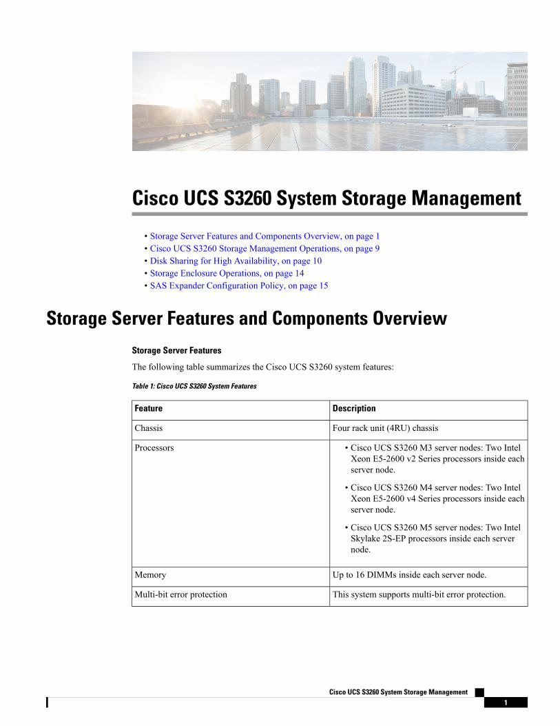
The following table summarizes the Cisco UCS S3260 system features:
Table 1: Cisco UCS S3260 System Features
DescriptionFeature
Four rack unit (4RU) chassisChassis
• Cisco UCS S3260 M3 server nodes: Two IntelXeon E5-2600 v2 Series processors inside eachserver node.
• Cisco UCS S3260 M4 server nodes: Two IntelXeon E5-2600 v4 Series processors inside eachserver node.
• Cisco UCS S3260 M5 server nodes: Two IntelSkylake 2S-EP processors inside each servernode.
Processors
Up to 16 DIMMs inside each server node.Memory
This system supports multi-bit error protection.Multi-bit error protection
Cisco UCS S3260 System Storage Management1
DescriptionFeature
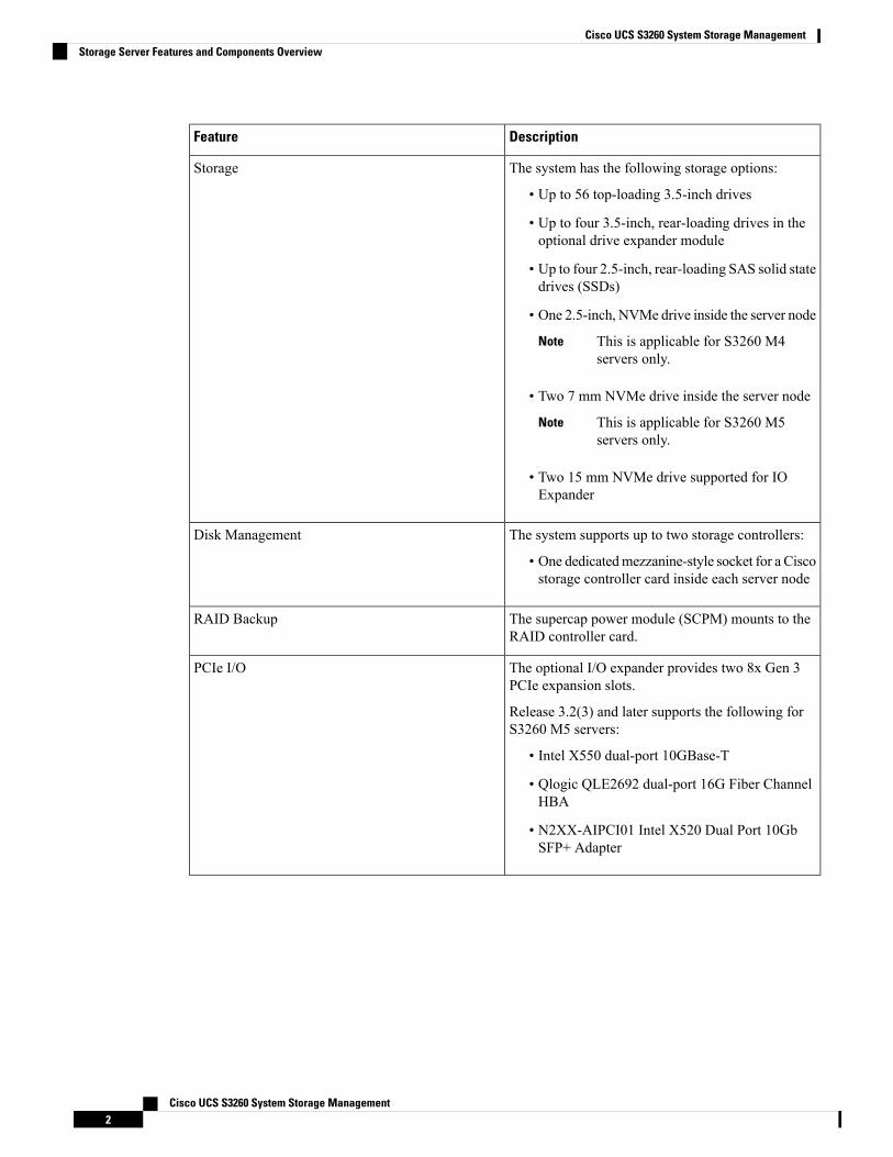
The system has the following storage options:
• Up to 56 top-loading 3.5-inch drives
• Up to four 3.5-inch, rear-loading drives in theoptional drive expander module
• Up to four 2.5-inch, rear-loading SAS solid statedrives (SSDs)
• One 2.5-inch, NVMe drive inside the server node
This is applicable for S3260 M4servers only.
Note
• Two 7 mm NVMe drive inside the server node
This is applicable for S3260 M5servers only.
Note
• Two 15 mm NVMe drive supported for IOExpander
Storage
The system supports up to two storage controllers:
• One dedicatedmezzanine-style socket for a Ciscostorage controller card inside each server node
Disk Management
The supercap power module (SCPM) mounts to theRAID controller card.
RAID Backup
The optional I/O expander provides two 8x Gen 3PCIe expansion slots.
Release 3.2(3) and later supports the following forS3260 M5 servers:
• Intel X550 dual-port 10GBase-T
• Qlogic QLE2692 dual-port 16G Fiber ChannelHBA
• N2XX-AIPCI01 Intel X520 Dual Port 10GbSFP+ Adapter
PCIe I/O
Cisco UCS S3260 System Storage Management2
Cisco UCS S3260 System Storage ManagementStorage Server Features and Components Overview
DescriptionFeature
The system can have one or two system I/O controllers(SIOCs). These provide rear-panel management anddata connectivity.
• Two SFP+ 40 Gb ports each SIOC.
• One 10/100/1000 Ethernet dedicatedmanagement port on each SIOC.
The server nodes each have one rear-panel KVMconnector that can be used with a KVM cable, whichprovides two USB, one VGA DB-15, and one serialDB-9 connector.
Network and Management I/O
Two or four power supplies, 1050 W each(hot-swappable and redundant as 2+2).
Power
Four internal fan modules that pull front-to-rearcooling, hot-swappable. Each fan module containstwo fans.
In addition, there is one fan in each power supply.
Cooling
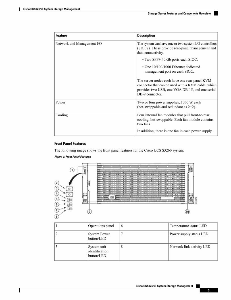
Front Panel Features
The following image shows the front panel features for the Cisco UCS S3260 system:Figure 1: Front Panel Features
Temperature status LED6Operations panel1
Power supply status LED7System Powerbutton/LED
2
Network link activity LED8System unitidentificationbutton/LED
3
Cisco UCS S3260 System Storage Management3
Cisco UCS S3260 System Storage ManagementStorage Server Features and Components Overview

Pull-out asset tag (not visibleunder front bezel)
9System status LED4
Internal-drive status LEDs10Fan status LED5
Rear Panel Features
The following image shows the rear panel features for the Cisco UCS S3260 system:Figure 2: Front Panel Features
Disk Slots
Not used at this time8Server bay 1
• (Optional) I/Oexpander, asshown (withCisco UCSS3260 M4 andM5 server nodeonly)
• (Optional)server node
• (Optional)driveexpansionmodule
1
Cisco UCS S3260 System Storage Management4
Cisco UCS S3260 System Storage ManagementStorage Server Features and Components Overview

Not used at this time9Server bay 2
• (Optional)server node(Cisco UCSS3260 M4 andM5 shown)
(Optional)driveexpansionmodule
2
Solid state drive bays (up tofour 2.5-inch SAS SSDs)
• SSDs in bays 1 and 2require a server node inserver bay 1
• SSDs in bays 3 and 4require a server node inserver bay 2
10System I/Ocontroller (SIOC)
• SIOC 1 isrequired if youhave a servernode in serverbay 1
• SIOC 2 isrequired if youhave servernode in serverbay 2
3
Cisco UCS S3260 M4 servernode label (M4 SVRN)
This label identifiesa Cisco UCS S3260M4 and M5 servernode. The CiscoUCS S3260 M3server node does nothave a label.
Note
11Power supplies(four, redundant as2+2)
4
KVM console connector (oneeach server node).
Used with a KVM cable thatprovides two USB, one VGA,and one serial connector
1240-Gb SFP+ ports(two on each SIOC)
5
Server node unit identificationbutton/LED
13ChassisManagementController (CMS)Debug FirmwareUtility port (oneeach SIOC)
6
Cisco UCS S3260 System Storage Management5
Cisco UCS S3260 System Storage ManagementStorage Server Features and Components Overview

Server node power button1410/100/1000dedicatedmanagement port,RJ-45 connector(one each SIOC)
7
Server node reset button (resetschipset in the server node
15
Storage Server Components
Server Nodes
The Cisco UCS S3260 system consists of one or two server nodes, each with two CPUs, DIMM memory of128, 256, or 512 GB, and a RAID card up to 4 GB cache or a pass-through controller. The server nodes canbe one of the following:
• Cisco UCS S3260 M3 Server Node
• Cisco UCS S3260 M4 Server Node—This node might include an optional I/O expander module thatattaches to the top of the server node.
• Cisco UCS S3260 M5 Server Node—This node might include an optional I/O expander module thatattaches to the top of the server node.
Disk Slots
The Cisco UCS S3260 chassis has 4 rows of 14 disk slots on the HDD motherboard and 4 additional diskslots on the HDD expansion tray. The following image shows the disk arrangement for the 56 top-accessible,hot swappable 3.5-inch 6 TB or 4 TB 7200 rpm NL-SAS HDD drives. A disk slot has two SAS ports andeach is connected a SAS expander in the chassis.Figure 3: Cisco UCS S3260 Top View
The following image shows the CiscoUCS S3260 chassis with the 4 additional disk slots on the HDD expansiontray.
Cisco UCS S3260 System Storage Management6
Cisco UCS S3260 System Storage ManagementStorage Server Features and Components Overview

Figure 4: Cisco UCS 3260 with the HDD expansion tray (Rear View)
If you have two server nodes with two SIOCs, you will have the following functionality:
1. The top server node works with the left SIOC (Server Slot1 with SIOC1).
2. The bottom server works with the right SIOC (Sever Slot 2 with SIOC2).
If you have one server node with two SIOCs, you can enable Server SIOCConnectivity functionality. Beginningwith release 3.1(3), Cisco UCS S3260 system supports Server SIOC Connectivity functionality. Using thisfunctionality, you can configure the data path through both the primary and auxiliary SIOCs when the chassishas single server and dual SIOCs set up.
SAS Expanders
The Cisco UCS S3260 system has two SAS expanders that run in redundant mode and connect the disks atthe chassis level to storage controllers on the servers. The SAS expanders provide two paths between a storagecontroller, and hence enable high availability. They provide the following functionality:
• Manage the pool of hard drives.
• Disk zone configuration of the hard drives to storage controllers on the servers.
Beginning with release 3.2(3a), Cisco UCS Manager can enable single path access to disk by configuringsingle DiskPort per disk slot. This ensures that the server discovers only a single device and avoid a multi-pathconfiguration.
The following table describes how the ports in each SAS expander are connected to the disks based on thetype of deployment.
ConnectivityPort range
Top accessible disks1-56
Disks in the HDD expansion tray.57-60
The number of SAS uplinks between storage controller and SAS expander can vary based on the type ofcontroller equipped in the server.
Note
Storage Enclosures
Cisco UCS S3260 System Storage Management7
Cisco UCS S3260 System Storage ManagementStorage Server Features and Components Overview
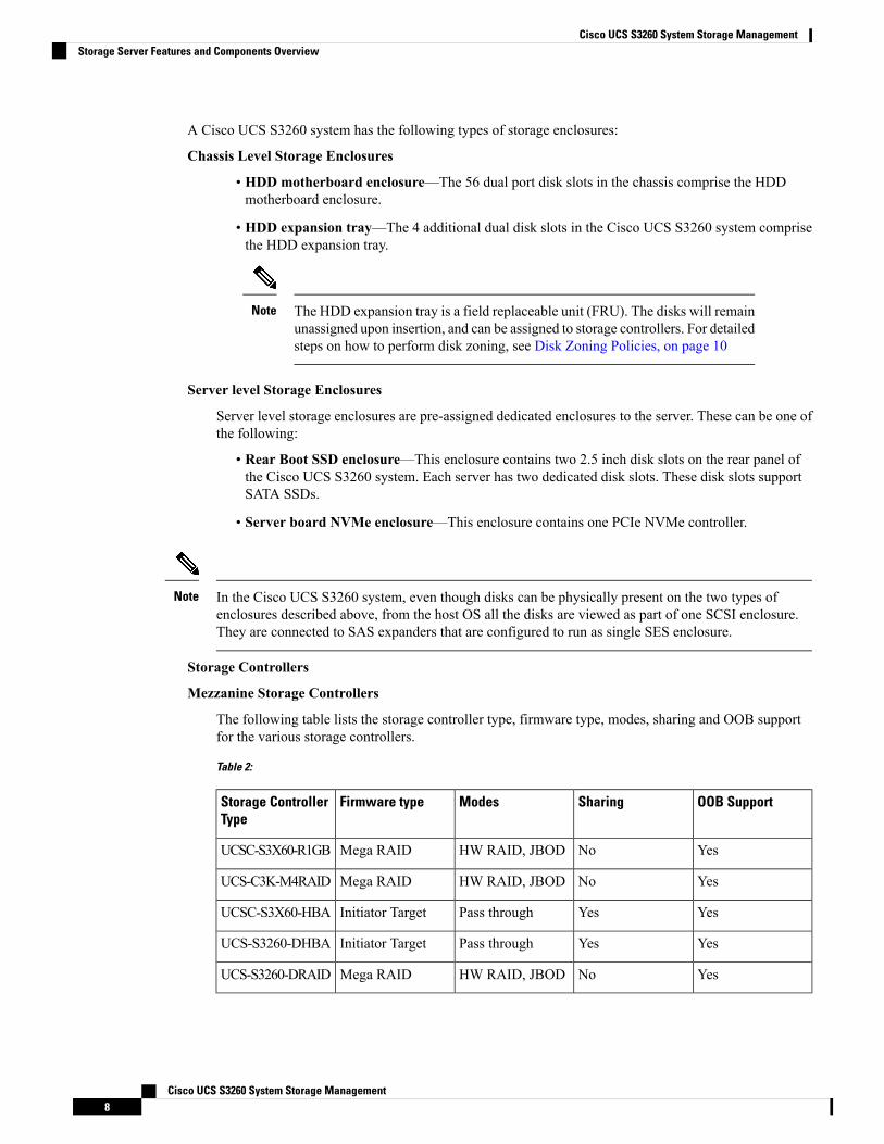
A Cisco UCS S3260 system has the following types of storage enclosures:
Chassis Level Storage Enclosures
• HDD motherboard enclosure—The 56 dual port disk slots in the chassis comprise the HDDmotherboard enclosure.
• HDD expansion tray—The 4 additional dual disk slots in the Cisco UCS S3260 system comprisethe HDD expansion tray.
The HDD expansion tray is a field replaceable unit (FRU). The disks will remainunassigned upon insertion, and can be assigned to storage controllers. For detailedsteps on how to perform disk zoning, see Disk Zoning Policies, on page 10
Note
Server level Storage Enclosures
Server level storage enclosures are pre-assigned dedicated enclosures to the server. These can be one ofthe following:
• Rear Boot SSD enclosure—This enclosure contains two 2.5 inch disk slots on the rear panel ofthe Cisco UCS S3260 system. Each server has two dedicated disk slots. These disk slots supportSATA SSDs.
• Server board NVMe enclosure—This enclosure contains one PCIe NVMe controller.
In the Cisco UCS S3260 system, even though disks can be physically present on the two types ofenclosures described above, from the host OS all the disks are viewed as part of one SCSI enclosure.They are connected to SAS expanders that are configured to run as single SES enclosure.
Note
Storage Controllers
Mezzanine Storage Controllers
The following table lists the storage controller type, firmware type, modes, sharing and OOB supportfor the various storage controllers.
Table 2:
OOB SupportSharingModesFirmware typeStorage ControllerType
YesNoHW RAID, JBODMega RAIDUCSC-S3X60-R1GB
YesNoHW RAID, JBODMega RAIDUCS-C3K-M4RAID
YesYesPass throughInitiator TargetUCSC-S3X60-HBA
YesYesPass throughInitiator TargetUCS-S3260-DHBA
YesNoHW RAID, JBODMega RAIDUCS-S3260-DRAID
Cisco UCS S3260 System Storage Management8
Cisco UCS S3260 System Storage ManagementStorage Server Features and Components Overview

Other storage controllersSW RAID Controller—The servers in the Cisco UCS S3260 system support two dedicated internalSSDs embedded into the PCIe riser that is connected to the SW RAID Controller. This controller issupported on the Cisco C3000 M3 servers.
NVMe Controller—This controller is used by servers in the Cisco UCS S3260 system for inventoryand firmware updates of NVMe disks.
For more details about the storage controllers supported in the various server nodes, see the related servicenote:
• Cisco UCS C3X60 M3 Server Node For Cisco UCS S3260 Storage Server Service Note
• Cisco UCS C3X60 M4 Server Node For Cisco UCS S3260 Storage Server Service Note
• Cisco UCS S3260 M5 Server Node For Cisco UCS S3260 Storage Server Service Note
Cisco UCS S3260 Storage Management OperationsThe following table summarizes the various storage management operations that you can perform with theCisco UCS Manager integrated Cisco UCS S3260 system.
See:DescriptionOperation
"Disk Zoning Policies" section in this guide.The SAS expanders in theCisco UCS S3260 system canmanage the pool of drives atthe chassis level. To sharedisks for high availability,perform the following:
1. Creating disk zoningpolicies.
2. Creating disk slots andassigning ownership.
3. Associating disks tochassis profile.
Disk Sharing for HighAvailability
"Storage Profiles" section in the Cisco UCSManager StorageManagementGuide, Release3.2.
You can utilize Cisco UCSManager's Storage Profile andDisk Group Policies fordefining storage disks, diskallocation andmanagement inthe Cisco UCS S3260 system.
Storage Profiles, Disk GroupsandDiskGroupConfigurationPolicies
"RemovingChassis Level Storage Enclosures"section in this guide.
You can swap the HDDexpansion tray with a server,or remove the tray if it waspreviously inserted.
Storage Enclosure Operations
Cisco UCS S3260 System Storage Management9
Cisco UCS S3260 System Storage ManagementCisco UCS S3260 Storage Management Operations
Disk Sharing for High Availability
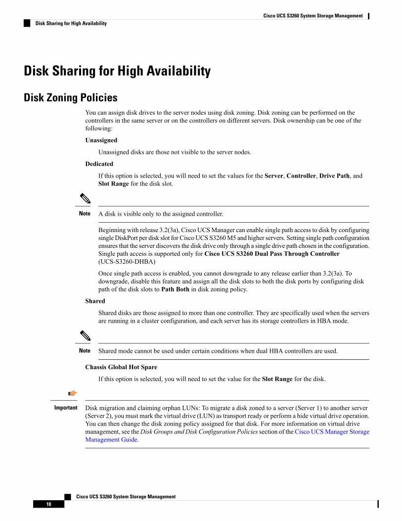
Disk Zoning PoliciesYou can assign disk drives to the server nodes using disk zoning. Disk zoning can be performed on thecontrollers in the same server or on the controllers on different servers. Disk ownership can be one of thefollowing:
Unassigned
Unassigned disks are those not visible to the server nodes.
Dedicated
If this option is selected, you will need to set the values for the Server, Controller, Drive Path, andSlot Range for the disk slot.
A disk is visible only to the assigned controller.Note
Beginning with release 3.2(3a), Cisco UCSManager can enable single path access to disk by configuringsingle DiskPort per disk slot for Cisco UCS S3260M5 and higher servers. Setting single path configurationensures that the server discovers the disk drive only through a single drive path chosen in the configuration.Single path access is supported only for Cisco UCS S3260 Dual Pass Through Controller(UCS-S3260-DHBA)
Once single path access is enabled, you cannot downgrade to any release earlier than 3.2(3a). Todowngrade, disable this feature and assign all the disk slots to both the disk ports by configuring diskpath of the disk slots to Path Both in disk zoning policy.
Shared
Shared disks are those assigned to more than one controller. They are specifically used when the serversare running in a cluster configuration, and each server has its storage controllers in HBA mode.
Shared mode cannot be used under certain conditions when dual HBA controllers are used.Note
Chassis Global Hot Spare
If this option is selected, you will need to set the value for the Slot Range for the disk.
Disk migration and claiming orphan LUNs: To migrate a disk zoned to a server (Server 1) to another server(Server 2), you must mark the virtual drive (LUN) as transport ready or perform a hide virtual drive operation.You can then change the disk zoning policy assigned for that disk. For more information on virtual drivemanagement, see theDisk Groups and Disk Configuration Policies section of the Cisco UCSManager StorageManagement Guide.
Important
Cisco UCS S3260 System Storage Management10
Cisco UCS S3260 System Storage ManagementDisk Sharing for High Availability

Creating a Disk Zoning Policy
Procedure
PurposeCommand or Action
Enters organization mode for the specified organization.To enter the root organization mode, type / as theorg-name .
UCS-A# scope org org-nameStep 1
Creates a disk zoning policy name with the specified diskzoning policy name.
UCS-A org/ # create disk-zoning-policy diskzoningpolicy-name
Step 2
Commits the transaction to the system configuration.UCS-A /org/disk-zoning-policy* # commit-bufferStep 3
Example
The following example creates the dzp1 disk zoning policy:
UCS-A# scope orgUCS-A /org # create disk-zoning-policy dzp1UCS-A /org/disk-zoning-policy*# commit-bufferUCS-A /org/disk-zoning-policy#
Creating Disk Slots and Assigning Ownership
Procedure
PurposeCommand or Action
Enters organization mode for the specified organization.To enter the root organization mode, type / as theorg-name .
UCS-A# scope org org-nameStep 1
Enters the disk zoning policy.UCS-A org/ # disk-zoning-policy disk-zoning-policy-nameStep 2
Creates disk slot with the specified slot number.UCS-A org/disk-zoning-policy # create disk-slot slot-idStep 3
Specifies the disk ownership to be one of the following:UCS-A org/disk-zoning-policy/disk-slot* # set ownershipownership-type{chassis-global-host-spare\dedicated\shared\unassigned}
Step 4
• chassis-global-hot-spare—Chassis Global Hot Spare
• dedicated—Dedicated
Beginning with release 3.2(3a), Cisco UCS Managercan enable single path access to disk by configuringsingle DiskPort per disk slot. This ensures that theserver discovers only a single device and avoid amulti-path configuration.
Drive Path options are:
Cisco UCS S3260 System Storage Management11
Cisco UCS S3260 System Storage ManagementCreating a Disk Zoning Policy
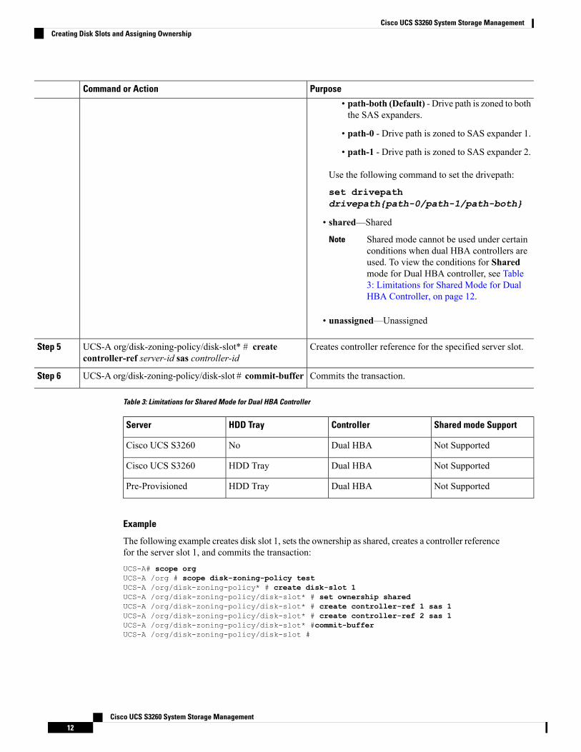
PurposeCommand or Action
• path-both (Default) - Drive path is zoned to boththe SAS expanders.
• path-0 - Drive path is zoned to SAS expander 1.
• path-1 - Drive path is zoned to SAS expander 2.
Use the following command to set the drivepath:
set drivepathdrivepath{path-0/path-1/path-both}
• shared—Shared
Shared mode cannot be used under certainconditions when dual HBA controllers areused. To view the conditions for Sharedmode for Dual HBA controller, see Table3: Limitations for Shared Mode for DualHBA Controller, on page 12.
Note
• unassigned—Unassigned
Creates controller reference for the specified server slot.UCS-A org/disk-zoning-policy/disk-slot* # createcontroller-ref server-id sas controller-id
Step 5
Commits the transaction.UCS-A org/disk-zoning-policy/disk-slot # commit-bufferStep 6
Table 3: Limitations for Shared Mode for Dual HBA Controller
Shared mode SupportControllerHDD TrayServer
Not SupportedDual HBANoCisco UCS S3260
Not SupportedDual HBAHDD TrayCisco UCS S3260
Not SupportedDual HBAHDD TrayPre-Provisioned
Example
The following example creates disk slot 1, sets the ownership as shared, creates a controller referencefor the server slot 1, and commits the transaction:UCS-A# scope orgUCS-A /org # scope disk-zoning-policy testUCS-A /org/disk-zoning-policy* # create disk-slot 1UCS-A /org/disk-zoning-policy/disk-slot* # set ownership sharedUCS-A /org/disk-zoning-policy/disk-slot* # create controller-ref 1 sas 1UCS-A /org/disk-zoning-policy/disk-slot* # create controller-ref 2 sas 1UCS-A /org/disk-zoning-policy/disk-slot* #commit-bufferUCS-A /org/disk-zoning-policy/disk-slot #
Cisco UCS S3260 System Storage Management12
Cisco UCS S3260 System Storage ManagementCreating Disk Slots and Assigning Ownership

Associating Disk Zoning Policies to Chassis Profile
Procedure
PurposeCommand or Action
Enters organization mode for the specified organization.To enter the root organization mode, type / as theorg-name .
UCS-A# scope org org-nameStep 1
Creates a chassis profile with the specified name.UCS-A org/ # create chassis-profile chassis-profile-nameStep 2
Sets the specified disk-zoning-policy.UCS-A org/chassis-profile* # set disk-zoning-policydisk-zoning-policy
Step 3
Commits the transaction.UCS-A org/chassis-profile* # commit-bufferStep 4
Associates the disks in the disk zoning policy to the chassiswith the specified chassis number.
UCS-A org/chassis-profile # associate chassis chassis-idStep 5
Example
The following example creates the ch1 chassis profile, sets the disk zoning policy all56shared,commits the transaction and associates the disk in the all56shared policy with chassis 3:UCS-A# scope orgUCS-A /org # create chassis-profile ch1UCS-A /org/chassis-profile* # set disk-zoning-policy all56sharedUCS-A /org/chassis-profile* # commit-bufferUCS-A /org/chassis-profile # associate chassis 3UCS-A /org/fw-chassis-pack/pack-image #
Disk MigrationBefore you can migrate a disk zoned from one server to another, you must mark the virtual drive(LUN) astransport ready or perform a hide virtual drive operation. This will ensure that all references from the serviceprofile have been removed prior to disk migration. For more information on virtual drives, please refer to the"virtual drives" section in the Cisco UCS Manager Storage Management Guide, Release 3.2.
Procedure
PurposeCommand or Action
Enters chassis mode for the specified chassis.UCS-A# scope chassis chassis-numStep 1
Enters the virtual drive container with the specified number.UCS-A /chassis# scope virtual-drive-containervirtual-drive-container-num
Step 2
Enters the virtual drive for the specified virtual drivecontainer.
UCS-A /chassis/virtual-drive-container# scopevirtual-drive virtual-drive--num
Step 3
Cisco UCS S3260 System Storage Management13
Cisco UCS S3260 System Storage ManagementAssociating Disk Zoning Policies to Chassis Profile
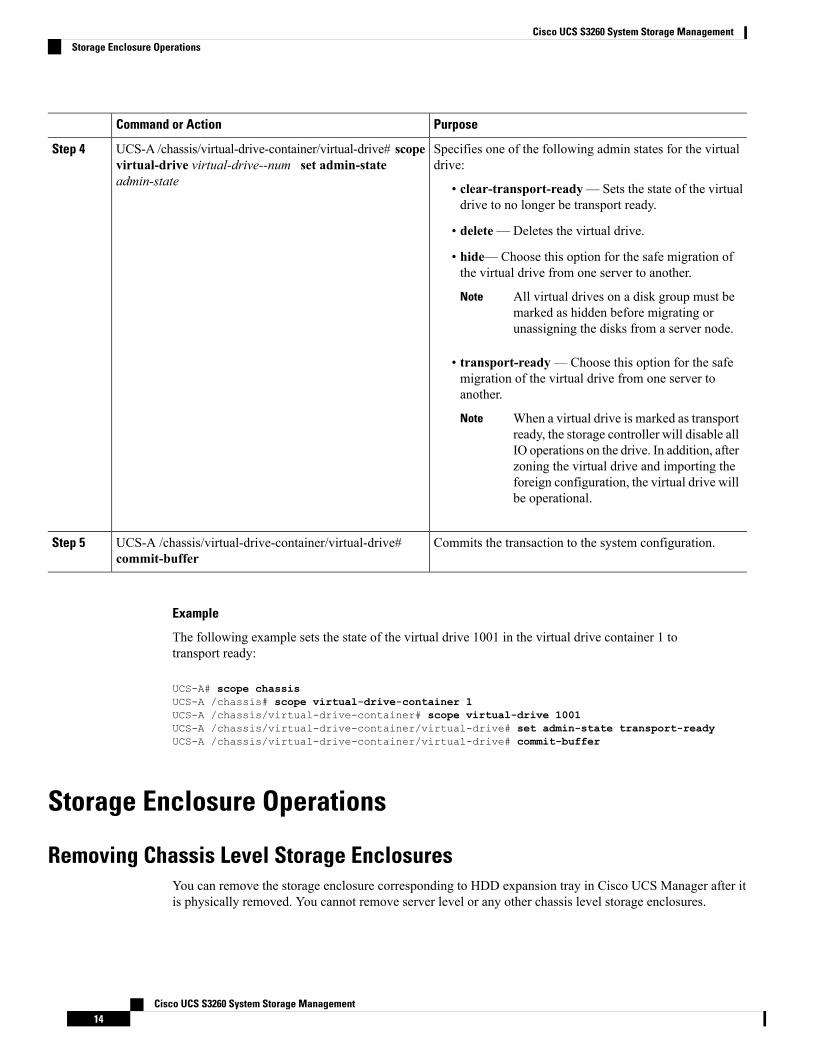
PurposeCommand or Action
Specifies one of the following admin states for the virtualdrive:
UCS-A /chassis/virtual-drive-container/virtual-drive# scopevirtual-drive virtual-drive--num set admin-stateadmin-state
Step 4
• clear-transport-ready— Sets the state of the virtualdrive to no longer be transport ready.
• delete—Deletes the virtual drive.
• hide—Choose this option for the safe migration ofthe virtual drive from one server to another.
All virtual drives on a disk group must bemarked as hidden before migrating orunassigning the disks from a server node.
Note
• transport-ready—Choose this option for the safemigration of the virtual drive from one server toanother.
When a virtual drive is marked as transportready, the storage controller will disable allIO operations on the drive. In addition, afterzoning the virtual drive and importing theforeign configuration, the virtual drive willbe operational.
Note
Commits the transaction to the system configuration.UCS-A /chassis/virtual-drive-container/virtual-drive#commit-buffer
Step 5
Example
The following example sets the state of the virtual drive 1001 in the virtual drive container 1 totransport ready:
UCS-A# scope chassisUCS-A /chassis# scope virtual-drive-container 1UCS-A /chassis/virtual-drive-container# scope virtual-drive 1001UCS-A /chassis/virtual-drive-container/virtual-drive# set admin-state transport-readyUCS-A /chassis/virtual-drive-container/virtual-drive# commit-buffer
Storage Enclosure Operations
Removing Chassis Level Storage EnclosuresYou can remove the storage enclosure corresponding to HDD expansion tray in Cisco UCS Manager after itis physically removed. You cannot remove server level or any other chassis level storage enclosures.
Cisco UCS S3260 System Storage Management14
Cisco UCS S3260 System Storage ManagementStorage Enclosure Operations
Procedure
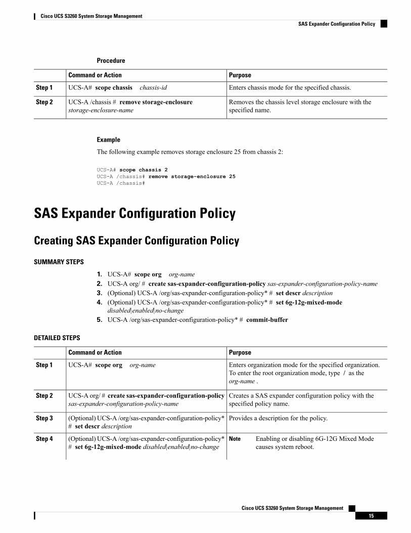
PurposeCommand or Action
Enters chassis mode for the specified chassis.UCS-A# scope chassis chassis-idStep 1
Removes the chassis level storage enclosure with thespecified name.
UCS-A /chassis # remove storage-enclosurestorage-enclosure-name
Step 2
Example
The following example removes storage enclosure 25 from chassis 2:
UCS-A# scope chassis 2UCS-A /chassis# remove storage-enclosure 25UCS-A /chassis#
SAS Expander Configuration Policy
Creating SAS Expander Configuration Policy
SUMMARY STEPS
1. UCS-A# scope org org-name2. UCS-A org/ # create sas-expander-configuration-policy sas-expander-configuration-policy-name3. (Optional) UCS-A /org/sas-expander-configuration-policy* # set descr description4. (Optional) UCS-A /org/sas-expander-configuration-policy* # set 6g-12g-mixed-mode
disabled|enabled|no-change5. UCS-A /org/sas-expander-configuration-policy* # commit-buffer
DETAILED STEPS
PurposeCommand or Action
Enters organization mode for the specified organization.To enter the root organization mode, type / as theorg-name .
UCS-A# scope org org-nameStep 1
Creates a SAS expander configuration policy with thespecified policy name.
UCS-A org/ # create sas-expander-configuration-policysas-expander-configuration-policy-name
Step 2
Provides a description for the policy.(Optional) UCS-A /org/sas-expander-configuration-policy*# set descr description
Step 3
(Optional) UCS-A /org/sas-expander-configuration-policy*# set 6g-12g-mixed-mode disabled|enabled|no-change
Step 4 Enabling or disabling 6G-12G Mixed Modecauses system reboot.
Note
Cisco UCS S3260 System Storage Management15
Cisco UCS S3260 System Storage ManagementSAS Expander Configuration Policy

PurposeCommand or Action
• Disabled—Connection Management is disabled inthis policy and the Sas Expander uses only 6G speedseven if 12G is available.
• Enabled—ConnectionManagement is enabled in thispolicy and it intelligently shifts between 6G and 12 Gspeeds based on availability.
• No Change (Default) —Pre-existing configuration isretained.
Commits the transaction to the system configuration.UCS-A /org/sas-expander-configuration-policy* #commit-buffer
Step 5
Example
The following example creates the secp1 SAS expander configuration policy:
UCS-A# scope orgUCS-A /org # create sas-expander-configuration-policy secp1UCS-A /org/sas-expander-configuration-policy*# set 6g-12g-mixed-mode enabledUCS-A /org/sas-expander-configuration-policy*# commit-bufferUCS-A /org/sas-expander-configuration-policy#
Deleting a SAS Expander Configuration Policy
SUMMARY STEPS
1. UCS-A# scope org org-name2. UCS-A org/ # delete sas-expander-configuration-policy sas-expander-configuration-policy-name3. UCS-A /org* # commit-buffer
DETAILED STEPS
PurposeCommand or Action
Enters organization mode for the specified organization.To enter the root organization mode, type / as theorg-name .
UCS-A# scope org org-nameStep 1
Deletes a SAS expander configuration policy with thespecified policy name.
UCS-A org/ # delete sas-expander-configuration-policysas-expander-configuration-policy-name
Step 2
Commits the transaction to the system configuration.UCS-A /org* # commit-bufferStep 3
Example
The following example deletes the secp1 SAS expander configuration policy:
Cisco UCS S3260 System Storage Management16
Cisco UCS S3260 System Storage ManagementDeleting a SAS Expander Configuration Policy

UCS-A# scope orgUCS-A /org # delete create sas-expander-configuration-policy secp1UCS-A /org*# commit-bufferUCS-A /org/#
Cisco UCS S3260 System Storage Management17
Cisco UCS S3260 System Storage ManagementDeleting a SAS Expander Configuration Policy

Cisco UCS S3260 System Storage Management18
Cisco UCS S3260 System Storage ManagementDeleting a SAS Expander Configuration Policy