Cisco UCS S3260 M5 Storage Server Disk I/O ......Cisco UCS S3260 Storage Server The Cisco UCS S3260...
24
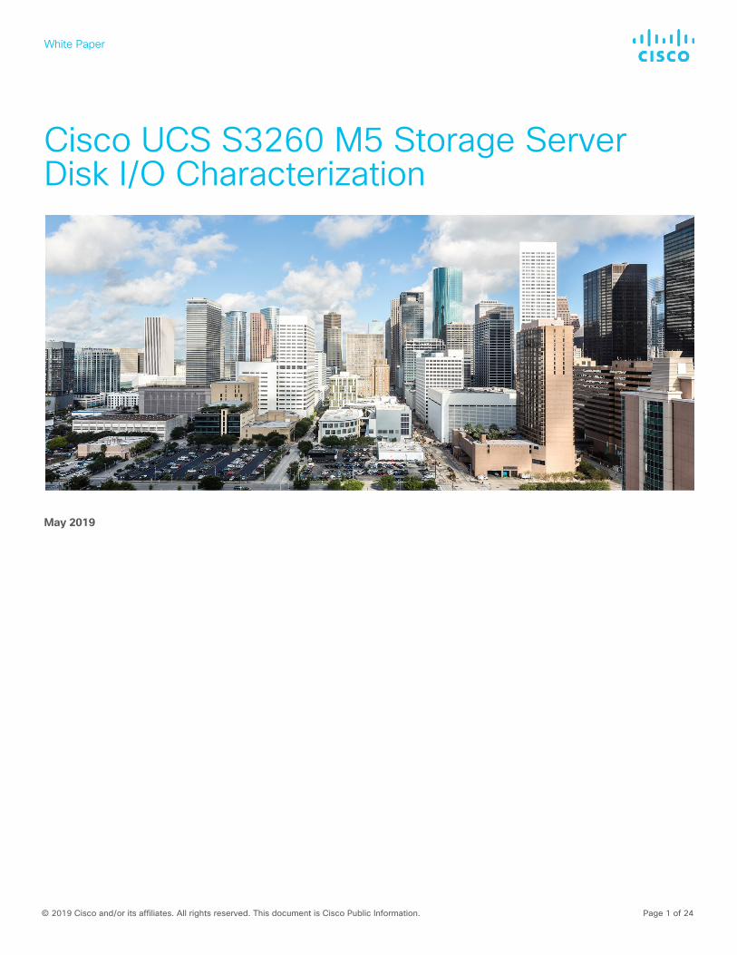
White Paper © 2019 Cisco and/or its affiliates. All rights reserved. This document is Cisco Public Information. Page 1 of 24 Cisco UCS S3260 M5 Storage Server Disk I/O Characterization May 2019
Transcript of Cisco UCS S3260 M5 Storage Server Disk I/O ......Cisco UCS S3260 Storage Server The Cisco UCS S3260...
White Paper
© 2019 Cisco and/or its affiliates. All rights reserved. This document is Cisco Public Information. Page 1 of 24
Cisco UCS S3260 M5 Storage Server Disk I/O Characterization
May 2019
White Paper
© 2019 Cisco and/or its affiliates. All rights reserved. This document is Cisco Public Information. Page 2 of 24
Contents Introduction ................................................................................................................................................................................... 3 Scope of this document ................................................................................................................................................................. 3 Hardware components .................................................................................................................................................................. 3
Cisco UCS S3260 Storage Server ............................................................................................................................................ 3 Server specifications ................................................................................................................................................................ 5
Storage components ..................................................................................................................................................................... 6 Hard-disk drives ....................................................................................................................................................................... 6 Boot drives ............................................................................................................................................................................... 6 Storage controller ..................................................................................................................................................................... 6 Virtual disk options ................................................................................................................................................................... 7
Workload characterization ............................................................................................................................................................. 8 Flexible I/O overview ................................................................................................................................................................ 8 Test parameters and configuration ......................................................................................................................................... 10
Hardware configuration ............................................................................................................................................................... 10 Software configuration ........................................................................................................................................................... 10 Virtual drive parameters for various RAID levels ...................................................................................................................... 11
Performance results .................................................................................................................................................................... 12 7200-rpm 10-TB HDD JBOD performance ................................................................................................................................. 12 7200-rpm 10-TB HDD RAID 0 performance ................................................................................................................................ 16 7200-rpm 10-TB HDD RAID 6 performance ................................................................................................................................ 20 For more information ................................................................................................................................................................... 24
White Paper
© 2019 Cisco and/or its affiliates. All rights reserved. This document is Cisco Public Information. Page 3 of 24
Introduction This document describes the I/O performance characteristics of the Cisco UCS® S3260 Storage Server using the embedded Cisco® 12-Gbps RAID controller. Performance comparisons of “just a bunch of disks” (JBOD) configuration, various redundant array of independent disk (RAID) configurations, and controller options are presented.
The performance data in this document was obtained using the Flexible I/O (fio) measurement tool, with analysis based on the metrics of input and output operations per second (IOPS) for random I/O workloads, and megabytes per second (MBps) throughput for sequential I/O workloads. From this analysis, specific recommendations are made for storage configuration parameters.
Many combinations of drive types and RAID levels are possible. For the characterization tests reported here, performance evaluations were limited to 10-terabyte (TB) 7200-rpm 3.5-inch large-form-factor (LFF) hard-disk drives (HDDs) with a JBOD mode configuration and RAID 0 and RAID 6 virtual disk configurations.
Scope of this document
For the I/O characterization tests, performance was evaluated using HDDs with a JBOD configuration and RAID 0 and RAID 6 virtual disks configurations, because many of the workloads targeted for Cisco UCS S3260 Storage Servers use these configurations. The S3260 server used for the I/O performance characterization tests supports up to 56 HDDs per server node and up to 2 boot SATA solid-state disks (SSDs).
Disk I/O performance for the S3260 was tested and validated on a single-server Cisco UCS S3260 M5 Storage Server node equipped with two Intel® Xeon® Scalable Gold 6132 processors, 192 GB of memory, fifty-six 10-TB 7200-rpm NL-SAS HDDs, and one 480-GB SSD boot drive.
Hardware components
Cisco UCS S3260 Storage Server
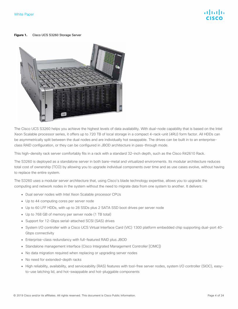
The Cisco UCS S3260 Storage Server (Figure 1) is a modular, high-density, high-availability dual-node rack server well suited for service providers, enterprises, and industry-specific environments. It addresses the need for dense cost-effective storage for ever-growing amounts of data. Designed for a new class of cloud-scale applications, it is simple to deploy and excellent for big data applications, software-defined storage environments, unstructured data repositories, media streaming, and content distribution.
White Paper
© 2019 Cisco and/or its affiliates. All rights reserved. This document is Cisco Public Information. Page 4 of 24
Figure 1. Cisco UCS S3260 Storage Server
The Cisco UCS S3260 helps you achieve the highest levels of data availability. With dual-node capability that is based on the Intel Xeon Scalable processor series, it offers up to 720 TB of local storage in a compact 4-rack-unit (4RU) form factor. All HDDs can be asymmetrically split between the dual nodes and are individually hot swappable. The drives can be built in to an enterprise-class RAID configuration, or they can be configured in JBOD architecture in pass-through mode.
This high-density rack server comfortably fits in a rack with a standard 32-inch depth, such as the Cisco R42610 Rack.
The S3260 is deployed as a standalone server in both bare-metal and virtualized environments. Its modular architecture reduces total cost of ownership (TCO) by allowing you to upgrade individual components over time and as use cases evolve, without having to replace the entire system.
The S3260 uses a modular server architecture that, using Cisco’s blade technology expertise, allows you to upgrade the computing and network nodes in the system without the need to migrate data from one system to another. It delivers:
● Dual server nodes with Intel Xeon Scalable processor CPUs
● Up to 44 computing cores per server node
● Up to 60 LFF HDDs, with up to 28 SSDs plus 2 SATA SSD boot drives per server node
● Up to 768 GB of memory per server node (1 TB total)
● Support for 12-Gbps serial-attached SCSI (SAS) drives
● System I/O controller with a Cisco UCS Virtual Interface Card (VIC) 1300 platform embedded chip supporting dual-port 40-Gbps connectivity
● Enterprise-class redundancy with full-featured RAID plus JBOD
● Standalone management interface (Cisco Integrated Management Controller [CIMC])
● No data migration required when replacing or upgrading server nodes
● No need for extended-depth racks
● High reliability, availability, and serviceability (RAS) features with tool-free server nodes, system I/O controller (SIOC), easy-to-use latching lid, and hot-swappable and hot-pluggable components
White Paper
© 2019 Cisco and/or its affiliates. All rights reserved. This document is Cisco Public Information. Page 5 of 24
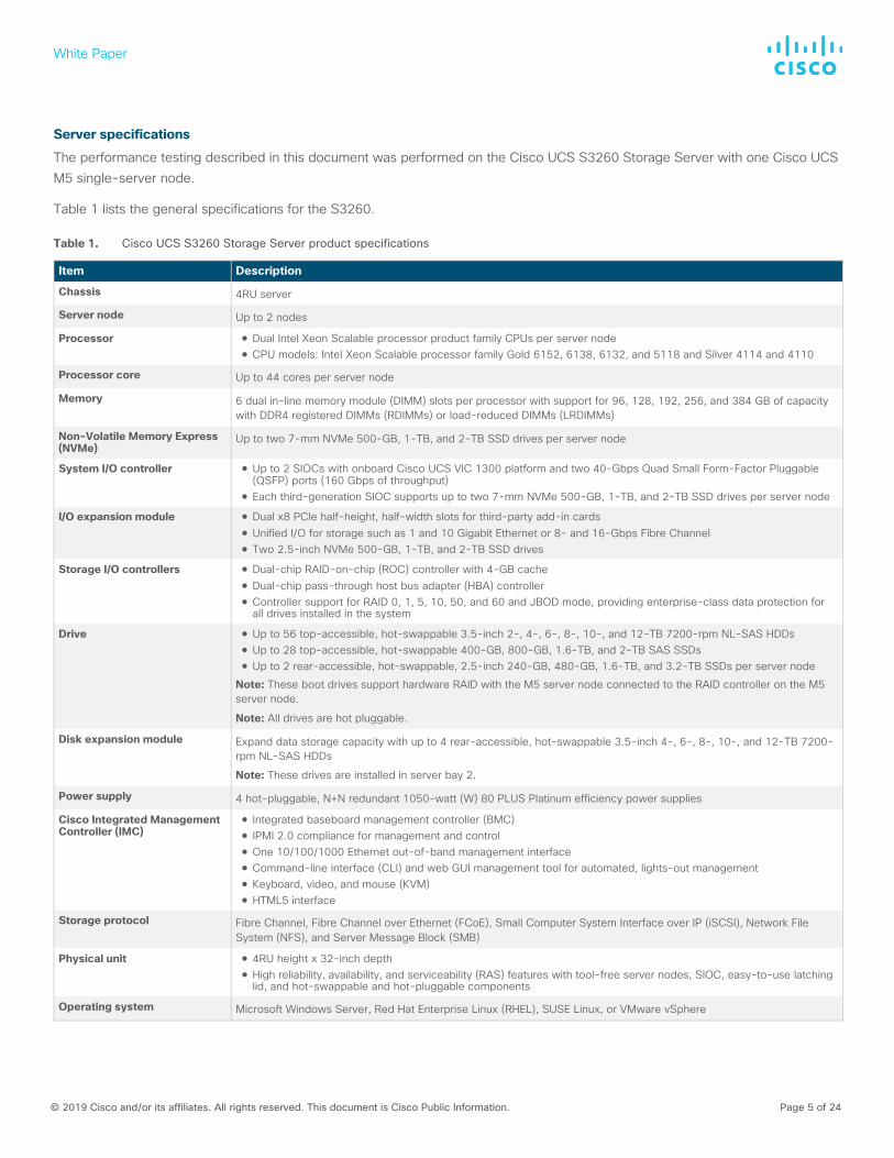
Server specifications
The performance testing described in this document was performed on the Cisco UCS S3260 Storage Server with one Cisco UCS M5 single-server node.
Table 1 lists the general specifications for the S3260.
Table 1. Cisco UCS S3260 Storage Server product specifications
Item Description
Chassis 4RU server
Server node Up to 2 nodes
Processor ● Dual Intel Xeon Scalable processor product family CPUs per server node ● CPU models: Intel Xeon Scalable processor family Gold 6152, 6138, 6132, and 5118 and Silver 4114 and 4110
Processor core Up to 44 cores per server node
Memory 6 dual in-line memory module (DIMM) slots per processor with support for 96, 128, 192, 256, and 384 GB of capacity with DDR4 registered DIMMs (RDIMMs) or load-reduced DIMMs (LRDIMMs)
Non-Volatile Memory Express (NVMe)
Up to two 7-mm NVMe 500-GB, 1-TB, and 2-TB SSD drives per server node
System I/O controller ● Up to 2 SIOCs with onboard Cisco UCS VIC 1300 platform and two 40-Gbps Quad Small Form-Factor Pluggable (QSFP) ports (160 Gbps of throughput)
● Each third-generation SIOC supports up to two 7-mm NVMe 500-GB, 1-TB, and 2-TB SSD drives per server node
I/O expansion module ● Dual x8 PCIe half-height, half-width slots for third-party add-in cards ● Unified I/O for storage such as 1 and 10 Gigabit Ethernet or 8- and 16-Gbps Fibre Channel ● Two 2.5-inch NVMe 500-GB, 1-TB, and 2-TB SSD drives
Storage I/O controllers ● Dual-chip RAID-on-chip (ROC) controller with 4-GB cache ● Dual-chip pass-through host bus adapter (HBA) controller ● Controller support for RAID 0, 1, 5, 10, 50, and 60 and JBOD mode, providing enterprise-class data protection for
all drives installed in the system
Drive ● Up to 56 top-accessible, hot-swappable 3.5-inch 2-, 4-, 6-, 8-, 10-, and 12-TB 7200-rpm NL-SAS HDDs ● Up to 28 top-accessible, hot-swappable 400-GB, 800-GB, 1.6-TB, and 2-TB SAS SSDs ● Up to 2 rear-accessible, hot-swappable, 2.5-inch 240-GB, 480-GB, 1.6-TB, and 3.2-TB SSDs per server node
Note: These boot drives support hardware RAID with the M5 server node connected to the RAID controller on the M5 server node.
Note: All drives are hot pluggable.
Disk expansion module Expand data storage capacity with up to 4 rear-accessible, hot-swappable 3.5-inch 4-, 6-, 8-, 10-, and 12-TB 7200-rpm NL-SAS HDDs
Note: These drives are installed in server bay 2.
Power supply 4 hot-pluggable, N+N redundant 1050-watt (W) 80 PLUS Platinum efficiency power supplies
Cisco Integrated Management Controller (IMC)
● Integrated baseboard management controller (BMC) ● IPMI 2.0 compliance for management and control ● One 10/100/1000 Ethernet out-of-band management interface ● Command-line interface (CLI) and web GUI management tool for automated, lights-out management ● Keyboard, video, and mouse (KVM) ● HTML5 interface
Storage protocol Fibre Channel, Fibre Channel over Ethernet (FCoE), Small Computer System Interface over IP (iSCSI), Network File System (NFS), and Server Message Block (SMB)
Physical unit ● 4RU height x 32-inch depth ● High reliability, availability, and serviceability (RAS) features with tool-free server nodes, SIOC, easy-to-use latching
lid, and hot-swappable and hot-pluggable components
Operating system Microsoft Windows Server, Red Hat Enterprise Linux (RHEL), SUSE Linux, or VMware vSphere
White Paper
© 2019 Cisco and/or its affiliates. All rights reserved. This document is Cisco Public Information. Page 6 of 24
For complete configuration details, please refer to the S3260 specifications sheet at https://www.cisco.com/c/dam/en/us/products/collateral/servers-unified-computing/ucs-c-series-rack-servers/c3260-spec-sheet.pdf.
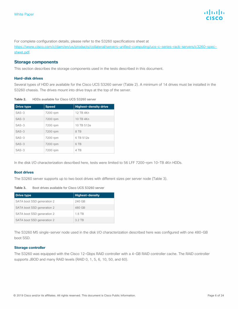
Storage components This section describes the storage components used in the tests described in this document.
Hard-disk drives
Several types of HDD are available for the Cisco UCS S3260 server (Table 2). A minimum of 14 drives must be installed in the S3260 chassis. The drives mount into drive trays at the top of the server.
Table 2. HDDs available for Cisco UCS S3260 server
Drive type Speed Highest-density drive
SAS-3 7200 rpm 12 TB 4Kn
SAS-3 7200 rpm 10 TB 4Kn
SAS-3 7200 rpm 10 TB 512e
SAS-3 7200 rpm 8 TB
SAS-3 7200 rpm 6 TB 512e
SAS-3 7200 rpm 6 TB
SAS-3 7200 rpm 4 TB
In the disk I/O characterization described here, tests were limited to 56 LFF 7200-rpm 10-TB 4Kn HDDs.
Boot drives
The S3260 server supports up to two boot drives with different sizes per server node (Table 3).
Table 3. Boot drives available for Cisco UCS S3260 server
Drive type Highest-density
SATA boot SSD generation 2 240 GB
SATA boot SSD generation 2 480 GB
SATA boot SSD generation 2 1.6 TB
SATA boot SSD generation 2 3.2 TB
The S3260 M5 single-server node used in the disk I/O characterization described here was configured with one 480-GB boot SSD.
Storage controller
The S3260 was equipped with the Cisco 12-Gbps RAID controller with a 4-GB RAID controller cache. The RAID controller supports JBOD and many RAID levels (RAID 0, 1, 5, 6, 10, 50, and 60).
White Paper
© 2019 Cisco and/or its affiliates. All rights reserved. This document is Cisco Public Information. Page 7 of 24
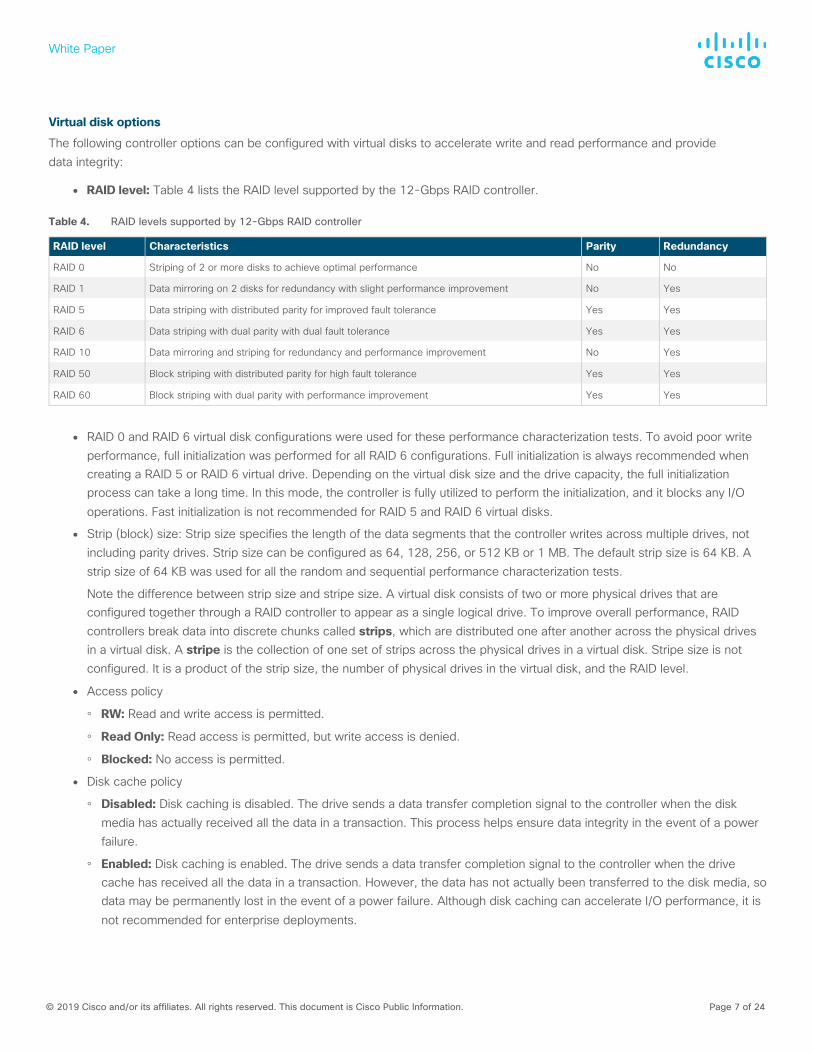
Virtual disk options
The following controller options can be configured with virtual disks to accelerate write and read performance and provide data integrity:
● RAID level: Table 4 lists the RAID level supported by the 12-Gbps RAID controller.
Table 4. RAID levels supported by 12-Gbps RAID controller
RAID level Characteristics Parity Redundancy
RAID 0 Striping of 2 or more disks to achieve optimal performance No No
RAID 1 Data mirroring on 2 disks for redundancy with slight performance improvement No Yes
RAID 5 Data striping with distributed parity for improved fault tolerance Yes Yes
RAID 6 Data striping with dual parity with dual fault tolerance Yes Yes
RAID 10 Data mirroring and striping for redundancy and performance improvement No Yes
RAID 50 Block striping with distributed parity for high fault tolerance Yes Yes
RAID 60 Block striping with dual parity with performance improvement Yes Yes
● RAID 0 and RAID 6 virtual disk configurations were used for these performance characterization tests. To avoid poor write performance, full initialization was performed for all RAID 6 configurations. Full initialization is always recommended when creating a RAID 5 or RAID 6 virtual drive. Depending on the virtual disk size and the drive capacity, the full initialization process can take a long time. In this mode, the controller is fully utilized to perform the initialization, and it blocks any I/O operations. Fast initialization is not recommended for RAID 5 and RAID 6 virtual disks.
● Strip (block) size: Strip size specifies the length of the data segments that the controller writes across multiple drives, not including parity drives. Strip size can be configured as 64, 128, 256, or 512 KB or 1 MB. The default strip size is 64 KB. A strip size of 64 KB was used for all the random and sequential performance characterization tests.
Note the difference between strip size and stripe size. A virtual disk consists of two or more physical drives that are configured together through a RAID controller to appear as a single logical drive. To improve overall performance, RAID controllers break data into discrete chunks called strips, which are distributed one after another across the physical drives in a virtual disk. A stripe is the collection of one set of strips across the physical drives in a virtual disk. Stripe size is not configured. It is a product of the strip size, the number of physical drives in the virtual disk, and the RAID level.
● Access policy
◦ RW: Read and write access is permitted.
◦ Read Only: Read access is permitted, but write access is denied.
◦ Blocked: No access is permitted.
● Disk cache policy
◦ Disabled: Disk caching is disabled. The drive sends a data transfer completion signal to the controller when the disk media has actually received all the data in a transaction. This process helps ensure data integrity in the event of a power failure.
◦ Enabled: Disk caching is enabled. The drive sends a data transfer completion signal to the controller when the drive cache has received all the data in a transaction. However, the data has not actually been transferred to the disk media, so data may be permanently lost in the event of a power failure. Although disk caching can accelerate I/O performance, it is not recommended for enterprise deployments.
White Paper
© 2019 Cisco and/or its affiliates. All rights reserved. This document is Cisco Public Information. Page 8 of 24
● I/O cache policy
◦ Direct: All read data is transferred directly to host memory, bypassing the RAID controller cache. Any read-ahead data is cached. All write data is transferred directly from host memory, bypassing the RAID controller cache if Write Through cache mode is set. The Direct policy is recommended for all configurations.
◦ Cached: All read and write data passes through the controller cache memory on its way to or from host memory. Subsequent read requests for the same data can then be addressed from the controller cache. Note that “cached I/O” refers to the caching of read data, and “read ahead” refers to the caching of speculative future read data.
● Read policy
◦ No Read Ahead (normal read): Only the requested data is read, and the controller does not read ahead any data.
◦ Always Read Ahead: The controller reads sequentially ahead of requested data and stores the additional data in cache memory, anticipating that the data will be needed soon.
● Write policy
◦ Write Through: Data is written directly to the disks. The controller sends a data transfer completion signal to the host when the drive subsystem has received all the data in a transaction.
◦ Write Back: Data is first written to the controller cache memory, and when the cache receives acknowledgment from the host, data is flushed to the disks. Data is written to the disks when the commit operation occurs at the controller cache. The controller sends a data transfer completion signal to the host when the controller cache has received all the data in a transaction.
◦ Write Back with Battery Backup: Battery backup is used to provide data integrity protection in the event of a power failure. Battery backup is always recommended for enterprise deployments.
Workload characterization This section provides an overview of fio, the I/O measurement tool that was used as a workload generator and as the means for measuring I/O performance in the various tests discussed in this document.
Flexible I/O overview
Flexible I/O, or fio, is a versatile I/O workload generator. It is flexible enough to allow detailed workload configurations, and it contains the reporting tools necessary to make sense of the data after tests are complete. Fio is widely used as an industry-standard benchmarking and stress-testing tool. It is also used for I/O verification purposes.
It supports workload options not found in other benchmarking tools as well as rigorously detailed I/O statistics. Any mix of random and sequential I/O operations and any mix of read and write operations are easy to define. The internal design of fio is flexible as well. Definition of a workload is completely separate from the I/O engine (a term fio uses to signify the way that I/O is delivered to the kernel).
Fio also supports three different types of output format: classic, comma-separated values (CSV), and JavaScript Object Notation (JSON). The classic output is the default; it dumps workload statistics at the end of the workload. The CSV format is also supported, though its use is slowly diminishing in favor of the JSON-based output format.
Fio spawns a number of threads, or processes, performing a particular type of I/O action as specified by the user. Fio uses a number of global parameters, each inherited by the thread unless other supplied parameters override a given setting. Fio typically is used to write a job file that matches the I/O load that you want to simulate.
White Paper
© 2019 Cisco and/or its affiliates. All rights reserved. This document is Cisco Public Information. Page 9 of 24
Configurable parameters include the following:
● Block size
● Percentage distribution of random and sequential operations
● Percentage distribution of read and write operations
● I/O size
● I/O engine
● Number of jobs
● Outstanding I/O
Fio collects a wide variety of measurement data, including the following:
● IOPS (average number of I/O operations performed)
● MBps (average bandwidth rate)
● File (dump information related to file actions)
● I/O (dump information related to I/O queuing)
● Average response time (total, read, and write)
● Mem (dump information related to memory allocations
● Maximum response time (total, read, and write)
● Submission latency
● Completion latency
● Errors
● Bytes read
● Bytes written
● Read I/O operations
● Write I/O operations
● Number of I/O operations performed by all groups
● Number of megabytes I/O operations performed
● Aggregate bandwidth of threads in the group
● Maximum size
● Queue depth
White Paper
© 2019 Cisco and/or its affiliates. All rights reserved. This document is Cisco Public Information. Page 10 of 24
The relevant metrics used for this performance characterization are IOPS and MBps:
● IOPS: I/O operations per second is a common performance metric used to measure computer storage devices, including HDDs. This metric is used to evaluate performance for random I/O workloads.
● MBps: Megabytes per second measures throughput, or the amount of data transferred to a computer storage device. This metric is used to evaluate performance for sequential I/O workloads. MBps should not be confused with Mbps, which refers to megabits per second.
More information is available at https://github.com/axboe/fio.
Test parameters and configuration
Tables 5 through 8 list the hardware and software configurations used for these I/O performance measurement tests, including server configuration, JBOD and RAID configurations, virtual drive parameters, fio settings, and BIOS settings.
Hardware configuration Table 5 lists the server configuration used for these tests.
Table 5. Server configuration
Product name Cisco UCS S3260 M5
Server node 1 x S3260 M5 server node
BIOS version Release S3X60M5.4.0.2a.0.1107180127
CPU 2 Intel Xeon Gold 6132 processors at 2.60 GHz
Number of cores 28
Number of threads 56
Total memory 192 GB
Memory DIMMs 192 GB: 12 x 16-GB RDIMMs at 1 DIMM per channel (DPC)
Memory speed 2666 MHz
RAID controller Cisco 12-Gbps SAS modular RAID controller
HDDs 56 x 10-TB 12-Gbps SAS 7200-rpm LFF HDDs (UCS-C3K-56HD10)
SIOC 1 x UCSS-S3260-SIOC with embedded Cisco UCS VIC 1300 platform
Software configuration
The software test configurations were as follows:
● The JBOD configuration was tested with up to 56 disks.
● For RAID 0 configurations, each RAID 0 virtual drive was created with a single disk.
● For RAID 6 configurations, each RAID 6 virtual drive was created with seven disks.
White Paper
© 2019 Cisco and/or its affiliates. All rights reserved. This document is Cisco Public Information. Page 11 of 24
Virtual drive parameters for various RAID levels
Table 6 lists the configuration parameters used for various RAID levels configured for the tests reported in this document.
Table 6. Virtual drive parameters for various RAID levels
Workload RAID level Strip size Disk cache policy I/O cache policy Read policy Write policy
Random I/O RAID 0 64 KB Disabled Direct I/O Always read ahead Write back good battery backup unit (BBU)
Random I/O RAID 6 64 KB Disabled Direct I/O Always read ahead Write back good BBU
Sequential I/O RAID 0 64 KB Disabled Direct I/O Always read ahead Write back good BBU
Sequential I/O RAID 6 64 KB Disabled Direct I/O Always read ahead Write back good BBU
Table 7 lists the fio settings used for various I/O tests performed for the I/O characterization.
Table 7. FIO settings
Name Value
Fio version Release 3.6
I/O engine libaio
Run time 15 minutes
Ramp-up time 90 seconds
Direct 1
I/O depth 64
Table 8 lists the BIOS settings used for various I/O tests performed for the I/O characterization.
Table 8. BIOS settings for Cisco UCS S3260 M5 (system under test)
Name Value
BIOS version Release S3X60M5.4.0.2a
Intel Hyper-Threading Technology Enabled
Number of enabled cores All
Execute disable bit Enabled
Intel Virtualization Technology (VT) Enabled
Intel VT for Directed I/O (VT-d) Enabled
Intel VT-d Coherency support Disabled
Intel VT-d Address Translation Services (ATS) support Enabled
CPU performance Enterprise
Hardware prefetcher Enabled
Adjacent cache line prefetcher Enabled
Data cache unit (DCU) streamer prefetch Enabled
DCU IP prefetcher Enabled
Enhanced Intel SpeedStep Technology Enabled
White Paper
© 2019 Cisco and/or its affiliates. All rights reserved. This document is Cisco Public Information. Page 12 of 24
Name Value
Intel Turbo Boost Technology Enabled
Processor power state C6 Disabled
Processor power state C1 enhanced Disabled
Package C-state C0/C1 state
P-state coordination Hardware all (HW ALL)
Hardware P-states Native mode
Energy performance Balanced performance
Power performance tuning OS controls
Sub-NUMA clustering (SNC) Disabled
Workload configuration Balanced
Select memory reliability, availability, and serviceability (RAS) Maximum performance
Non-uniform memory access (NUMA) Enabled
IMC interleaving Auto
XPT prefetch Disabled
UPI prefetch Enabled
Patrol scrub Enabled
Altitude 300 meters
Performance results The performance data mentioned in this section was obtained using the fio measurement tool, with analysis based on the IOPS rate for random I/O workloads and on MBps throughput for sequential I/O workloads. From this analysis, specific recommendations can be made for storage configuration parameters.
The server specifications and BIOS settings used in these performance characterization tests are detailed in Table 5 and Table 8.
The I/O performance test results capture the maximum read IOPS and bandwidth achieved with the HDDs.
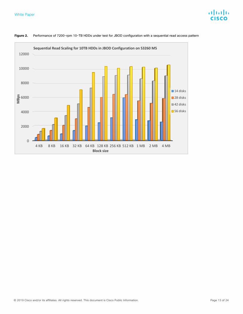
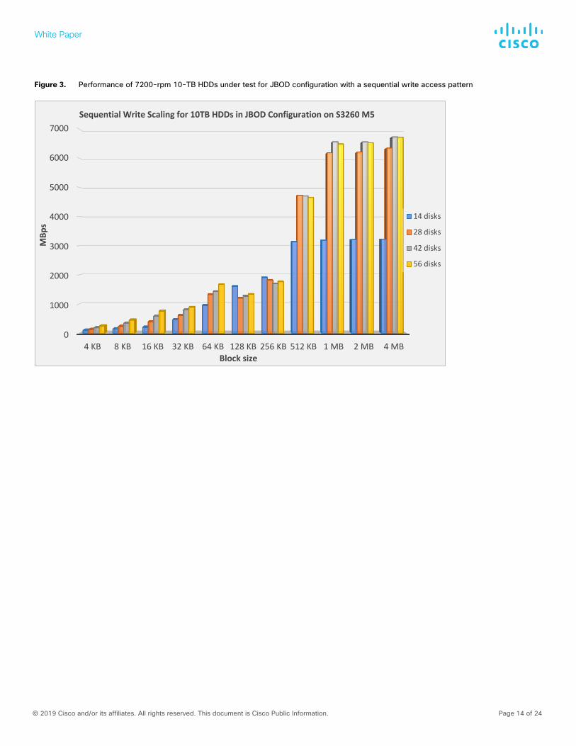
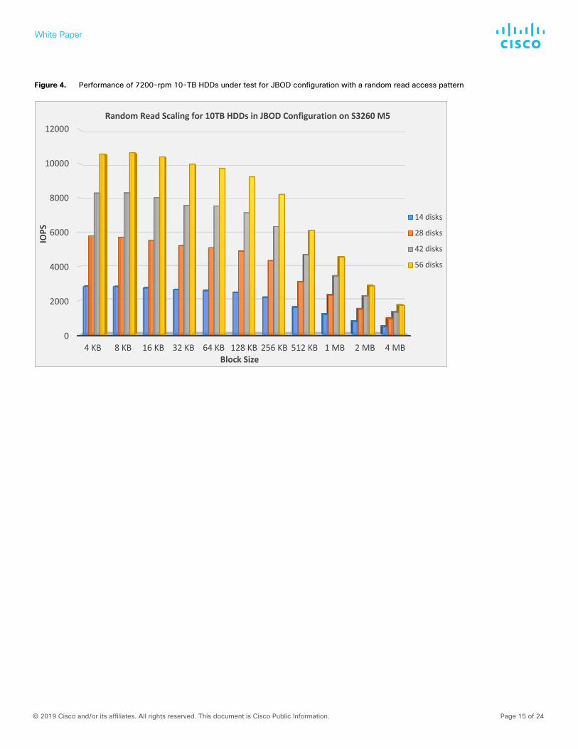
7200-rpm 10-TB HDD JBOD performance The graphs in Figures 2 through 5 were prepared from fio measurement data. They illustrate the I/O performance of 10-TB 7200-rpm LFF HDDs configured in a Cisco UCS S3260 M5 single-server node with 14 disks, 28 disks, 42 disks, and 56 disks in JBOD mode. These tests were performed to achieve the best performance from these drives without concern for latency.
White Paper
© 2019 Cisco and/or its affiliates. All rights reserved. This document is Cisco Public Information. Page 13 of 24
Figure 2. Performance of 7200-rpm 10-TB HDDs under test for JBOD configuration with a sequential read access pattern
0
2000
4000
6000
8000
10000
12000
4 KB 8 KB 16 KB 32 KB 64 KB 128 KB 256 KB 512 KB 1 MB 2 MB 4 MB
MBp
s
Block size
Sequential Read Scaling for 10TB HDDs in JBOD Configuration on S3260 M5
14 disks
28 disks
42 disks
56 disks
White Paper
© 2019 Cisco and/or its affiliates. All rights reserved. This document is Cisco Public Information. Page 14 of 24
Figure 3. Performance of 7200-rpm 10-TB HDDs under test for JBOD configuration with a sequential write access pattern
0
1000
2000
3000
4000
5000
6000
7000
4 KB 8 KB 16 KB 32 KB 64 KB 128 KB 256 KB 512 KB 1 MB 2 MB 4 MB
MBp
s
Block size
Sequential Write Scaling for 10TB HDDs in JBOD Configuration on S3260 M5
14 disks
28 disks
42 disks
56 disks
White Paper
© 2019 Cisco and/or its affiliates. All rights reserved. This document is Cisco Public Information. Page 15 of 24
Figure 4. Performance of 7200-rpm 10-TB HDDs under test for JBOD configuration with a random read access pattern
0
2000
4000
6000
8000
10000
12000
4 KB 8 KB 16 KB 32 KB 64 KB 128 KB 256 KB 512 KB 1 MB 2 MB 4 MB
IOPS
Block Size
Random Read Scaling for 10TB HDDs in JBOD Configuration on S3260 M5
14 disks
28 disks
42 disks
56 disks
White Paper
© 2019 Cisco and/or its affiliates. All rights reserved. This document is Cisco Public Information. Page 16 of 24
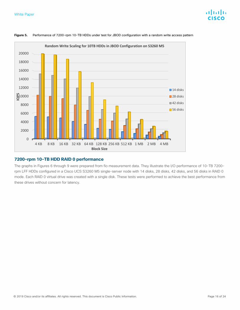
Figure 5. Performance of 7200-rpm 10-TB HDDs under test for JBOD configuration with a random write access pattern
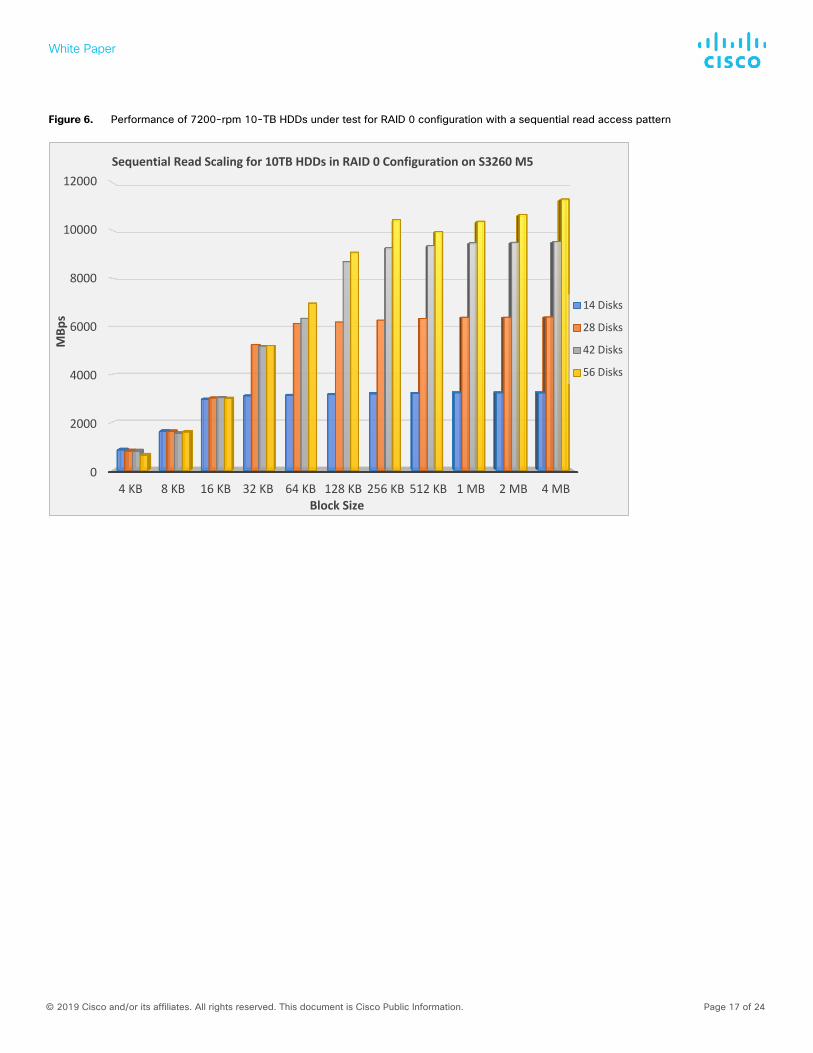
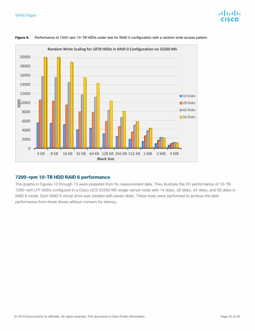
7200-rpm 10-TB HDD RAID 0 performance The graphs in Figures 6 through 9 were prepared from fio measurement data. They illustrate the I/O performance of 10-TB 7200-rpm LFF HDDs configured in a Cisco UCS S3260 M5 single-server node with 14 disks, 28 disks, 42 disks, and 56 disks in RAID 0 mode. Each RAID 0 virtual drive was created with a single disk. These tests were performed to achieve the best performance from these drives without concern for latency.
0
2000
4000
6000
8000
10000
12000
14000
16000
18000
20000
4 KB 8 KB 16 KB 32 KB 64 KB 128 KB 256 KB 512 KB 1 MB 2 MB 4 MB
IOPS
Block Size
Random Write Scaling for 10TB HDDs in JBOD Configuration on S3260 M5
14 disks
28 disks
42 disks
56 disks
White Paper
© 2019 Cisco and/or its affiliates. All rights reserved. This document is Cisco Public Information. Page 17 of 24
Figure 6. Performance of 7200-rpm 10-TB HDDs under test for RAID 0 configuration with a sequential read access pattern
0
2000
4000
6000
8000
10000
12000
4 KB 8 KB 16 KB 32 KB 64 KB 128 KB 256 KB 512 KB 1 MB 2 MB 4 MB
MBp
s
Block Size
Sequential Read Scaling for 10TB HDDs in RAID 0 Configuration on S3260 M5
14 Disks
28 Disks
42 Disks
56 Disks
White Paper
© 2019 Cisco and/or its affiliates. All rights reserved. This document is Cisco Public Information. Page 18 of 24
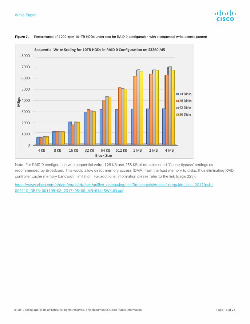
Figure 7. Performance of 7200-rpm 10-TB HDDs under test for RAID 0 configuration with a sequential write access pattern
Note: For RAID 0 configuration with sequential write, 128 KB and 256 KB block sizes need ‘Cache bypass’ settings as recommended by Broadcom. This would allow direct memory access (DMA) from the host memory to disks, thus eliminating RAID controller cache memory bandwidth limitation. For additional information please refer to the link (page 223):
https://www.cisco.com/c/dam/en/us/td/docs/unified_computing/ucs/3rd-party/lsi/mrsas/userguide_june_2017/pub-005110_DB15-001199-08_2017-06-09_MR-614-SW-UG.pdf
0
1000
2000
3000
4000
5000
6000
7000
8000
4 KB 8 KB 16 KB 32 KB 64 KB 512 KB 1 MB 2 MB 4 MB
MBp
s
Block Size
Sequential Write Scaling for 10TB HDDs in RAID 0 Configuration on S3260 M5
14 Disks
28 Disks
42 Disks
56 Disks
White Paper
© 2019 Cisco and/or its affiliates. All rights reserved. This document is Cisco Public Information. Page 19 of 24
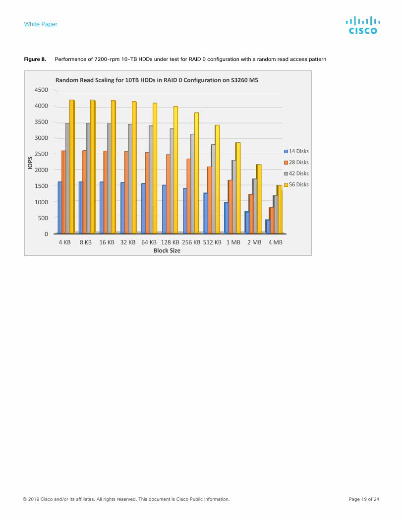
Figure 8. Performance of 7200-rpm 10-TB HDDs under test for RAID 0 configuration with a random read access pattern
0
500
1000
1500
2000
2500
3000
3500
4000
4500
4 KB 8 KB 16 KB 32 KB 64 KB 128 KB 256 KB 512 KB 1 MB 2 MB 4 MB
IOPS
Block Size
Random Read Scaling for 10TB HDDs in RAID 0 Configuration on S3260 M5
14 Disks
28 Disks
42 Disks
56 Disks
White Paper
© 2019 Cisco and/or its affiliates. All rights reserved. This document is Cisco Public Information. Page 20 of 24
Figure 9. Performance of 7200-rpm 10-TB HDDs under test for RAID 0 configuration with a random write access pattern
7200-rpm 10-TB HDD RAID 6 performance The graphs in Figures 10 through 13 were prepared from fio measurement data. They illustrate the I/O performance of 10-TB 7200-rpm LFF HDDs configured in a Cisco UCS S3260 M5 single-server node with 14 disks, 28 disks, 42 disks, and 56 disks in RAID 6 mode. Each RAID 6 virtual drive was created with seven disks. These tests were performed to achieve the best performance from these drives without concern for latency.
0
2000
4000
6000
8000
10000
12000
14000
16000
18000
20000
4 KB 8 KB 16 KB 32 KB 64 KB 128 KB 256 KB 512 KB 1 MB 2 MB 4 MB
IOPS
Block Size
Random Write Scaling for 10TB HDDs in RAID 0 Configuration on S3260 M5
14 Disks
28 Disks
42 Disks
56 Disks
White Paper
© 2019 Cisco and/or its affiliates. All rights reserved. This document is Cisco Public Information. Page 21 of 24
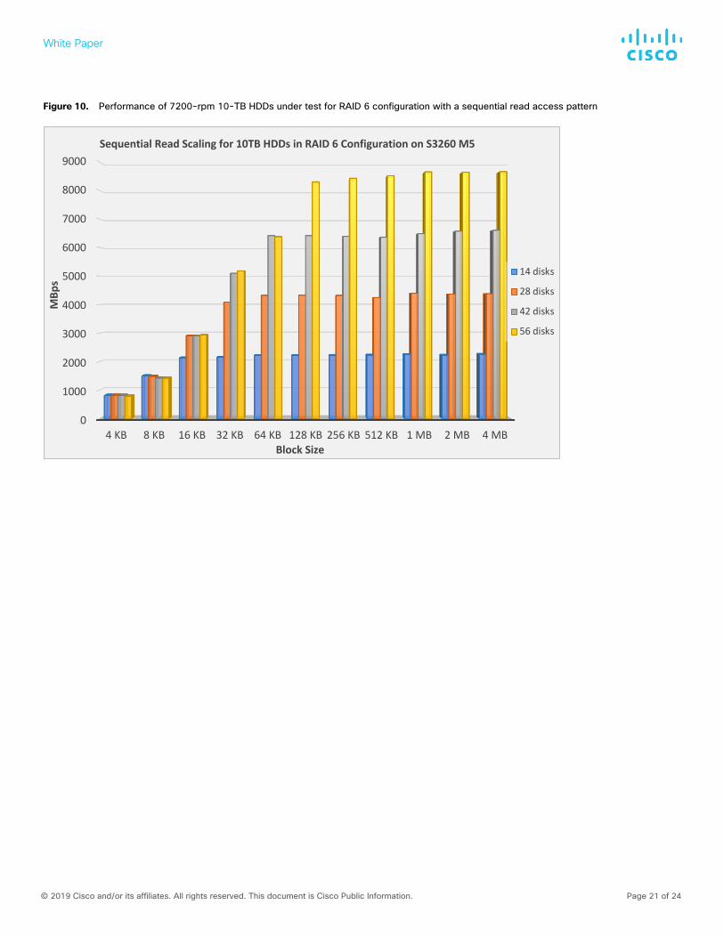
Figure 10. Performance of 7200-rpm 10-TB HDDs under test for RAID 6 configuration with a sequential read access pattern
0
1000
2000
3000
4000
5000
6000
7000
8000
9000
4 KB 8 KB 16 KB 32 KB 64 KB 128 KB 256 KB 512 KB 1 MB 2 MB 4 MB
MBp
s
Block Size
Sequential Read Scaling for 10TB HDDs in RAID 6 Configuration on S3260 M5
14 disks
28 disks
42 disks
56 disks
White Paper
© 2019 Cisco and/or its affiliates. All rights reserved. This document is Cisco Public Information. Page 22 of 24
Figure 11. Performance of 7200-rpm 10-TB HDDs under test for RAID 6 configuration with a sequential write access pattern
0
500
1000
1500
2000
2500
3000
3500
4000
4500
5000
4 KB 8 KB 16 KB 32 KB 64 KB 128 KB 256 KB 512 KB 1 MB 2 MB 4 MB
MBp
s
Block Size
Sequential Write Scaling for 10TB HDDs in RAID 6 Configuration on S3260 M5
14 disks
28 disks
42 disks
56 disks
White Paper
© 2019 Cisco and/or its affiliates. All rights reserved. This document is Cisco Public Information. Page 23 of 24
Figure 12. Performance of 7200-rpm 10-TB HDDs under test for RAID 6 configuration with a random read access pattern
0
500
1000
1500
2000
2500
3000
3500
4 KB 8 KB 16 KB 32 KB 64 KB 128 KB 256 KB 512 KB 1 MB 2 MB 4 MB
IOPS
Block Size
Random Read Scaling for 10TB HDDs in RAID 6 Configuration on S3260 M5
14 Disks
28 Disks
42 Disks
56 Disks
White Paper
© 2019 Cisco and/or its affiliates. All rights reserved. This document is Cisco Public Information. Page 24 of 24
Figure 13. Performance of 7200-rpm 10-TB HDDs under test for RAID 6 configuration with a random write access pattern
For more information For additional information, see:
● http://www.cisco.com/c/en/us/products/servers-unified-computing/ucs-s-series-storage-servers/index.html
● http://www.cisco.com/c/en/us/products/collateral/servers-unified-computing/ucs-s-series-storage-servers/datasheet-c78-738059.html
● http://www.cisco.com/c/dam/en/us/products/collateral/servers-unified-computing/ucs-s-series-storage-servers/s3260-specsheet.pdf
0
500
1000
1500
2000
2500
3000
4 KB 8 KB 16 KB 32 KB 64 KB 128 KB 256 KB 512 KB 1 MB 2 MB 4 MB
IOPS
Block Size
Random Write Scaling for 10TB HDDs in RAID 6 Configuration on S3260 M5
14 Disks
28 Disks
42 Disks
56 Disks
Printed in USA C11-740695-02 05/19