Cisco UCS B200 M3 Blade Server Installation and Service Note · Cisco UCS B200 M3 Blade Server...
36
Cisco UCS B200 M3 Blade Server Installation and Service Note 2 Cisco UCS B200 M3 Blade Server 2 Related Documentation 33 Obtaining Documentation and Submitting a Service Request 34
Transcript of Cisco UCS B200 M3 Blade Server Installation and Service Note · Cisco UCS B200 M3 Blade Server...

Cisco UCS B200 M3 Blade Server Installation and Service Note
2
Cisco UCS B200 M3 Blade Server 2
Related Documentation 33
Obtaining Documentation and Submitting a Service Request 34

Revised: June 13, 2013, OL-26624-01
Cisco UCS B200 M3 Blade ServerThe Cisco UCS B200 M3 is an Intel-based, half-width blade supporting two CPU sockets using Intel E5-2600 series CPUs and upto 24 DIMMs; it supports one modular LOM (dedicated slot for Cisco's Virtual Interface Card) and one mezzanine adapter. At thistime, the UCS B200 M2 (second generation) server is still available and is documented elsewhere. You can install up to eight UCSB200 Blade Servers to a UCS chassis, mixing with other models or Cisco UCS blade servers in the chassis if desired.
Figure 1: Cisco UCS B200 M3 Front Panel
Network link status LED7Asset tag 11
Blade health LED8Blade ejector handle2
Console connector9Ejector captive screw3
Reset button access10Hard drive bay 14
Beaconing LED and button11Hard drive bay 25
Power button and LED6
1 Each server has a blank plastic tag that pulls out of the front panel which is provided so that you can add your own asset tracking label without interfering withthe intended air flow.
LEDsServer LEDs indicate whether the blade server is in active or standby mode, the status of the network link, the over all health of theblade server, and whether the server is set to give a flashing blue beaconing indication.
The removable drives also have LEDs indicating hard disk access activity and disk health.
2

Table 1: Blade Server LEDs
DescriptionColorLED
Power off.OffPower
Normal operation.Green
Standby.Amber
None of the network links are up.OffLink
At least one network link is up.Green
Power off.OffHealth
Normal operation.Green
Minor error.Amber
Critical error.BlinkingAmber
Beaconing not enabled.OffBeaconing
Beaconing to locate a selected blade—If the LED is not blinking, theblade is not selected. You can initiate beaconing in UCSManager or withthe button.
Blinking blue1 Hz
Inactive.OffActivity
(Disk Drive)Outstanding I/O to disk drive.Green
Rebuild in progress. Health LED will flash in unison.FlashingAmber 4 Hz
Identify drive active.FlashingAmber 4 hz
Can mean either no fault detected or the drive is not installed.OffHealth
(Disk Drive)Identify drive active. If the Activity LED is also flashing amber, a driverebuild is in progress.
FlashingAmber 4 hz
Fault detected.Amber
3
ButtonsThe Reset button is just inside the chassis and must be pressed using the tip of a paper clip or a similar item. Hold the button downfor five seconds, and then release it to restart the server if other methods of restarting are not working.
The beaconing function for an individual server may get turned on or off by pressing the combination button and LED.
The power button and LED allows you to manually take a server temporarily out of service but leave it in a state where it can berestarted quickly. If the desired power state for a service profile associated with a blade server or an integrated rack-mount server isset to "off", using the power button or Cisco UCS Manager to reset the server will cause the desired power state of the server tobecome out of sync with the actual power state and the server may unexpected shutdown at a later time. To safely reboot a serverfrom a power-down state, use the Boot Server action in Cisco UCS Manager.
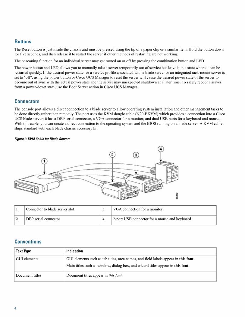
ConnectorsThe console port allows a direct connection to a blade server to allow operating system installation and other management tasks tobe done directly rather than remotely. The port uses the KVM dongle cable (N20-BKVM) which provides a connection into a CiscoUCS blade server; it has a DB9 serial connector, a VGA connector for a monitor, and dual USB ports for a keyboard and mouse.With this cable, you can create a direct connection to the operating system and the BIOS running on a blade server. A KVM cableships standard with each blade chassis accessory kit.
Figure 2: KVM Cable for Blade Servers
VGA connection for a monitor3Connector to blade server slot1
2-port USB connector for a mouse and keyboard4DB9 serial connector2
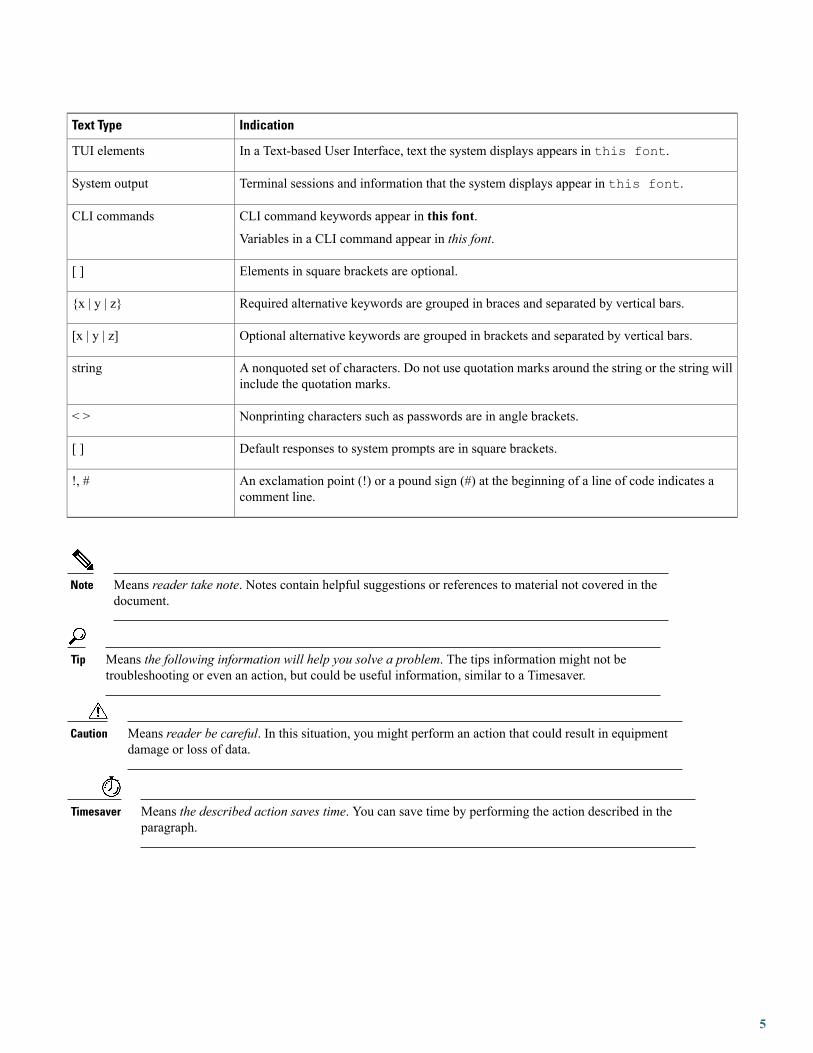
Conventions
IndicationText Type
GUI elements such as tab titles, area names, and field labels appear in this font.
Main titles such as window, dialog box, and wizard titles appear in this font.
GUI elements
Document titles appear in this font.Document titles
4
IndicationText Type
In a Text-based User Interface, text the system displays appears in this font.TUI elements
Terminal sessions and information that the system displays appear in this font.System output
CLI command keywords appear in this font.
Variables in a CLI command appear in this font.
CLI commands
Elements in square brackets are optional.[ ]
Required alternative keywords are grouped in braces and separated by vertical bars.{x | y | z}
Optional alternative keywords are grouped in brackets and separated by vertical bars.[x | y | z]
A nonquoted set of characters. Do not use quotation marks around the string or the string willinclude the quotation marks.
string
Nonprinting characters such as passwords are in angle brackets.< >
Default responses to system prompts are in square brackets.[ ]
An exclamation point (!) or a pound sign (#) at the beginning of a line of code indicates acomment line.
!, #
Means reader take note. Notes contain helpful suggestions or references to material not covered in thedocument.
Note
Means the following information will help you solve a problem. The tips information might not betroubleshooting or even an action, but could be useful information, similar to a Timesaver.
Tip
Means reader be careful. In this situation, you might perform an action that could result in equipmentdamage or loss of data.
Caution
Means the described action saves time. You can save time by performing the action described in theparagraph.
Timesaver
5

IMPORTANT SAFETY INSTRUCTIONS
This warning symbol means danger. You are in a situation that could cause bodily injury. Before youwork on any equipment, be aware of the hazards involved with electrical circuitry and be familiar withstandard practices for preventing accidents. Use the statement number provided at the end of each warningto locate its translation in the translated safety warnings that accompanied this device.
SAVE THESE INSTRUCTIONS
Warning
Installing and Removing a Blade Server Hard DriveThere are up to two front-accessible, hot-swappable, 2.5-inch drives per blade. An LSI SAS 2004 RAID controller is embedded inthe motherboard (it is not separately replaceable), and it supports RAID 0 and 1. You can remove blade server hard drives withoutremoving the blade server from the chassis. All other component replacements for a blade server requires removing the blade fromthe chassis. Unused hard drive bays should always be covered with cover plates (N20-BBLKD) to ensure proper cooling and ventilation.The chassis is omitted from illustrations here to simplify the drawing.
To prevent ESD damage, wear grounding wrist straps during these procedures and handle modules by thecarrier edges only.
Caution
If you ever need to move a RAID cluster from one server to another, both the old and new servers for thecluster must use the same LSI controller. For example, migration from a server with an LSI 1064E to aserver with an LSI MegaRAID is not supported. Migrating a RAID cluster from a B200 M1 or M2 to thisserver is not supported.
Caution
Replacing an HDD or SSDwith a drive of the same size, model, and manufacturer generally causes few problems with UCSManager.If the drive being replaced was part of a RAID array we recommend using a newly ordered drive of identical size, model, andmanufacturer to replace the failed drive. Cisco recommends following industry standard practice of using drives of the same capacitywhen creating RAID volumes. If drives of different capacities are used, the useable portion of the smallest drive will be used on alldrives that make up the RAID volume. Before upgrading or adding an HDD to a running system, check the service profile in UCSManager and make sure the new hardware configuration will be within the parameters allowed by the service profile.
Hard disk and RAID troubleshooting information is in the "Troubleshooting Server Hardware" chapter of the Cisco UCSTroubleshooting Guide.
The drives supported in this blade server are all hot pluggable and comewith the drive sled attached. Spare drive sleds are not available.The drives supported in this blade server are constantly being updated. A list of currently supported and available drives is in thespecification sheets at:
http://www.cisco.com/en/US/products/ps10280/products_data_sheets_list.htmlThe onboard RAID controller supports the following RAID levels:
• RAID 0 (data striping): Data is striped across all disks in the array, which provides fast throughput. There is no data redundancy,and all data is lost if any disk fails.
• RAID 1 (disk mirroring): Data is written to two disks, which provides complete data redundancy if one disk fails. The maximumarray size is equal to the available space on the smaller of the two drives.
6

• RAID 5 (disk striping with distributed parity): Data is striped across all disks in the array. Part of the capacity of each disk storesparity information that can be used to reconstruct data if a disk fails. RAID 5 provides good data throughput for applicationswith high read request rates.
• RAID 10 (combination of RAID 0 and RAID 1): data is striped across mirrored drives. RAID 10 breaks up data into smallerblocks and mirrors the blocks of data to each RAID 1 drive group. The first RAID 1 drive in each drive group then duplicatesits data to the second drive. The size of each block is determined by the stripe size parameter, which is set during the creationof the RAID set. The RAID 1 virtual drives must have the same stripe size.
Removing a Blade Server Hard Drive
To remove a hard drive from a blade server, follow these steps:
Procedure
Step 1 Push the button to release the ejector, and then pull the hard drive from its slot.
Figure 3: Removing the Hard Drive
Step 2 Place the hard drive on an antistatic mat or antistatic foam if you are not immediately reinstalling it in another server.Step 3 Install a hard disk drive blank faceplate (N20-BBLKD) to keep dust out of the blade server if the slot will remain empty.
Installing a Blade Server Hard Drive
To install a blade server hard drive in a blade server, follow these steps:
7
Procedure
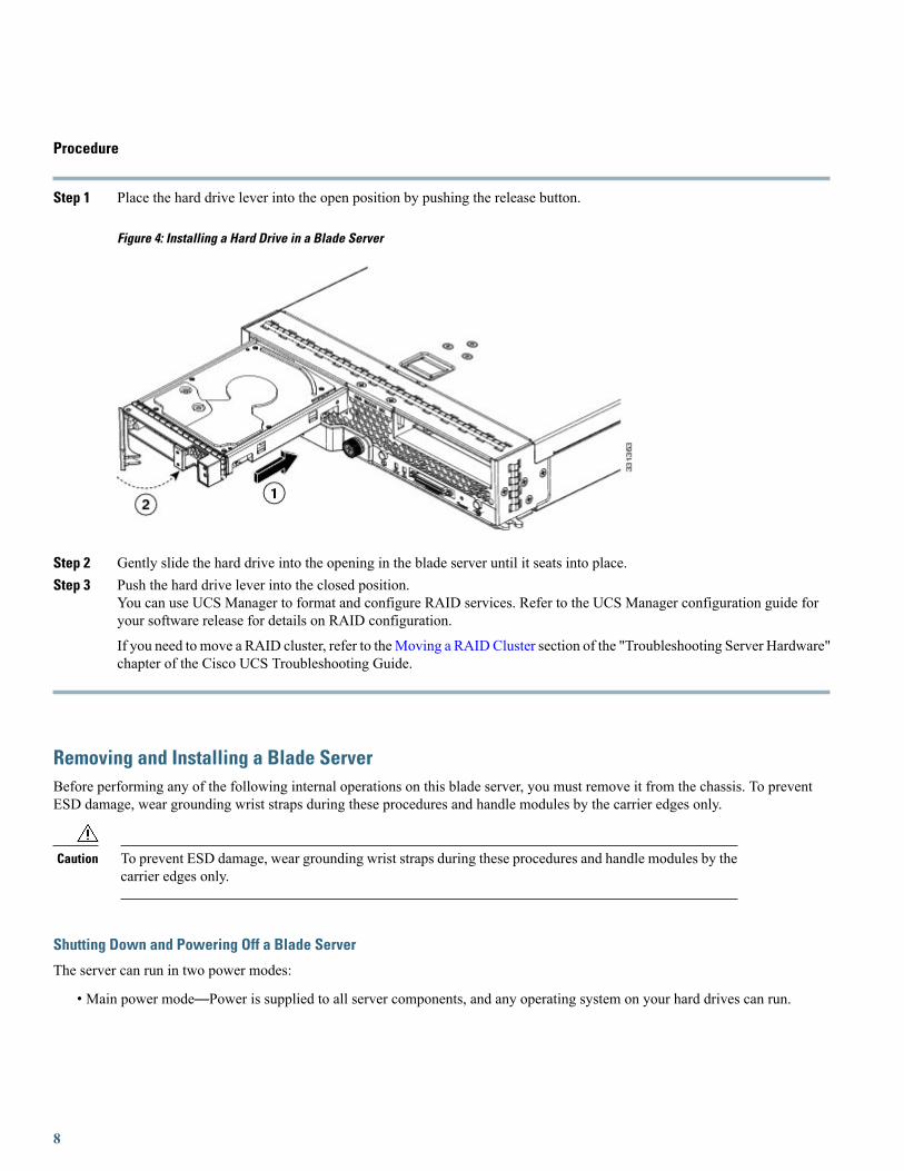
Step 1 Place the hard drive lever into the open position by pushing the release button.
Figure 4: Installing a Hard Drive in a Blade Server
Step 2 Gently slide the hard drive into the opening in the blade server until it seats into place.Step 3 Push the hard drive lever into the closed position.
You can use UCS Manager to format and configure RAID services. Refer to the UCS Manager configuration guide foryour software release for details on RAID configuration.
If you need to move a RAID cluster, refer to theMoving a RAIDCluster section of the "Troubleshooting Server Hardware"chapter of the Cisco UCS Troubleshooting Guide.
Removing and Installing a Blade ServerBefore performing any of the following internal operations on this blade server, you must remove it from the chassis. To preventESD damage, wear grounding wrist straps during these procedures and handle modules by the carrier edges only.
To prevent ESD damage, wear grounding wrist straps during these procedures and handle modules by thecarrier edges only.
Caution
Shutting Down and Powering Off a Blade Server
The server can run in two power modes:
• Main power mode—Power is supplied to all server components, and any operating system on your hard drives can run.
8
• Standby power mode—Power is supplied only to the service processor and the cooling fans, and it is safe to power off the serverfrom this mode.
After establishing a connection to the blade server’s operating system, you can directly shut down the blade server using the operatingsystem.
You can invoke a graceful shutdown or an emergency shutdown (hard shutdown) by using either of the following methods:
• Use the UCS Manager. See either the Cisco UCS Manager GUI Configuration Guide or the Cisco UCS Manager CLIConfiguration Guide.
• Use the Power button on the server front panel.
To use the Power button, follow these steps:
Procedure
Step 1 Check the color of the Power Status LED.
• Green indicates that the server is in main power mode and must be shut down before it can be safely powered off.Go to Step 2.
• Amber indicates that the server is already in standby mode and can be safely powered off. Go to Step 3.
Step 2 Invoke either a graceful shutdown or a hard shutdown:To avoid data loss or damage to your operating system, you should always invoke a graceful shutdown of theoperating system.
Caution
• Graceful shutdown—Press and release the Power button. The operating system performs a graceful shutdown andthe server goes to standby mode, which is indicated by an amber Power Status LED.
• Emergency shutdown—Press and hold the Power button for 4 seconds to force the main power off and immediatelyenter standby mode.
Step 3 If you are shutting down all blade servers in a chassis, you should now disconnect the power cords from the chassis tocompletely power off the servers. If you are only shutting down one server, you can skip unplugging the chassis and moveto removing the server.
Removing a Blade Server
Using UCS Manager, decommission the server before physically removing the server. To remove a blade server from the chassis,follow these steps:
9
Procedure
Step 1 Loosen the captive screw on the front of the blade.Step 2 Remove the blade from the chassis by pulling the ejector lever on the blade until it unseats the blade server.Step 3 Slide the blade part of the way out of the chassis, and place your other hand under the blade to support its weight.Step 4 Once removed, place the blade on an antistatic mat or antistatic foam if you are not immediately reinstalling it into another
slot.Step 5 If the slot is to remain empty, install a blank faceplate (N20-CBLKB1) to keep dust out of the chassis.
Installing a Half-width Blade Server
UCS B200 M3 and UCS B22 M3 half-width blade servers are interoperable in a UCS chassis with any other UCS blade servers,including prior generation B200 M2 and B200 M1 servers, or other UCS B-Series blade servers. To install a half-width blade server,follow these steps:
10

Procedure
Step 1 Grasp the front of the blade server and place your other hand under the blade to support it.
Figure 5: Positioning a Blade Server in the Chassis
Step 2 Open the ejector lever in the front of the blade server.Step 3 Gently slide the blade into the opening until you cannot push it any farther.Step 4 Press the ejector lever so that it catches the edge of the chassis and presses the blade server all the way in.Step 5 Tighten the captive screw on the front of the blade to no more than 3 in-lbs. Tightening with bare fingers only is unlikely
to lead to stripped or damaged captive screws.Step 6 Power on the server. UCS Manager automatically reacknowledges, reassociates, and recommissions the server, provided
any hardware changes are allowed by the service profile.
11
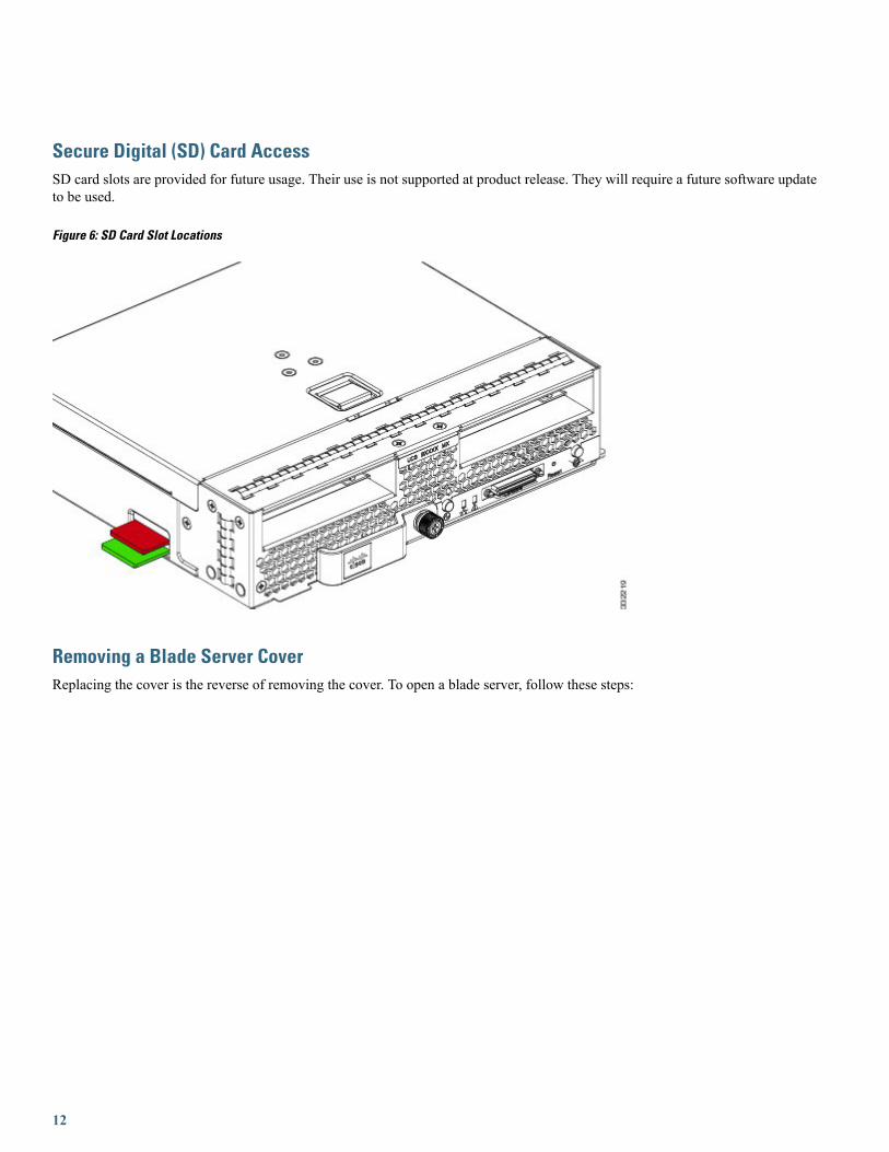
Secure Digital (SD) Card AccessSD card slots are provided for future usage. Their use is not supported at product release. They will require a future software updateto be used.
Figure 6: SD Card Slot Locations
Removing a Blade Server CoverReplacing the cover is the reverse of removing the cover. To open a blade server, follow these steps:
12
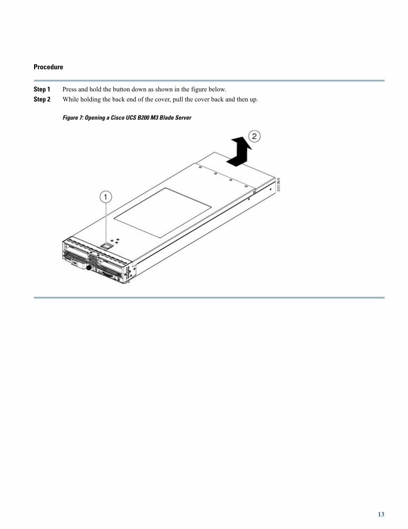
Procedure
Step 1 Press and hold the button down as shown in the figure below.Step 2 While holding the back end of the cover, pull the cover back and then up.
Figure 7: Opening a Cisco UCS B200 M3 Blade Server
13
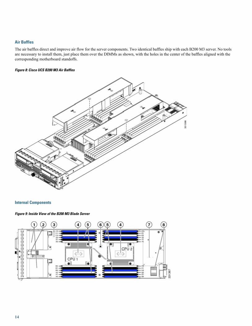
Air Baffles
The air baffles direct and improve air flow for the server components. Two identical baffles ship with each B200 M3 server. No toolsare necessary to install them, just place them over the DIMMs as shown, with the holes in the center of the baffles aligned with thecorresponding motherboard standoffs.
Figure 8: Cisco UCS B200 M3 Air Baffles
Internal Components
Figure 9: Inside View of the B200 M3 Blade Server
14

Internal USB connector 22Hard drive bays1
CPU and heat sink4Battery3
Diagnostic button6DIMM slots5
Adapter card connector (Adapter not shown installed)8Modular LOM (shown installed)7
2 Cisco UCS-USBFLSH-S-4GB= is recommended, but if another USB drive will be used it must be no wider than .8 inches, and no more than 1.345 inches longin order tp provide needed clearances to install or remove the USB drive.
Diagnostics Button and LEDs
At blade start-up, POST diagnostics test the CPUs, DIMMs, HDDs, and adapter cards, and any failure notifications are sent to UCSManager. You can view these notifications in the System Error Log or in the output of the show tech-support command. If errorsare found, an amber diagnostic LED also lights up next to the failed component. During run time, the blade BIOS, component drivers,and OS all monitor for hardware faults and will light up the amber diagnostic LED for a component if an uncorrectable error orcorrectable errors (such as a host ECC error) over the allowed threshold occur.
LED states are saved, and if you remove the blade from the chassis the LED values will persist for up to 10 minutes. Pressing theLED diagnostics button on the motherboard causes the LEDs that currently show a component fault to light for up to 30 seconds foreasier component identification. LED fault values are reset when the blade is reinserted into the chassis and booted, and the processbegins from its start.
If DIMM insertion errors are detected, they may cause the blade discovery to fail and errors will be reported in the server POSTinformation, which is viewable using the UCS Manager GUI or CLI. UCS blade servers require specific rules to be followed whenpopulating DIMMs in a blade server, and the rules depend on the blade server model. Refer to the documentation for a specific bladeserver for those rules.
HDD status LEDs are on the front face of the HDD. Faults on the CPU, DIMMs, or adapter cards also cause the server health LEDto light solid amber for minor error conditions or blinking amber for critical error conditions.
Working Inside the Blade ServerAll tasks in the following sections require that the server be removed from the Cisco UCS 5108 chassis.
Installing a Motherboard CMOS Battery
All Cisco UCS blade servers use a CR2032 battery (Cisco PID N20-MBLIBATT=) to preserve BIOS settings while the server ispowered down.
There is danger of explosion if the battery is replaced incorrectly. Replace the battery only with the sameor equivalent type recommended by the manufacturer. Dispose of used batteries according to themanufacturer’s instructions. Statement 1015
Warning
To install or replace a motherboard complementary metal-oxide semiconductor (CMOS) battery, follow these steps:
15
Procedure
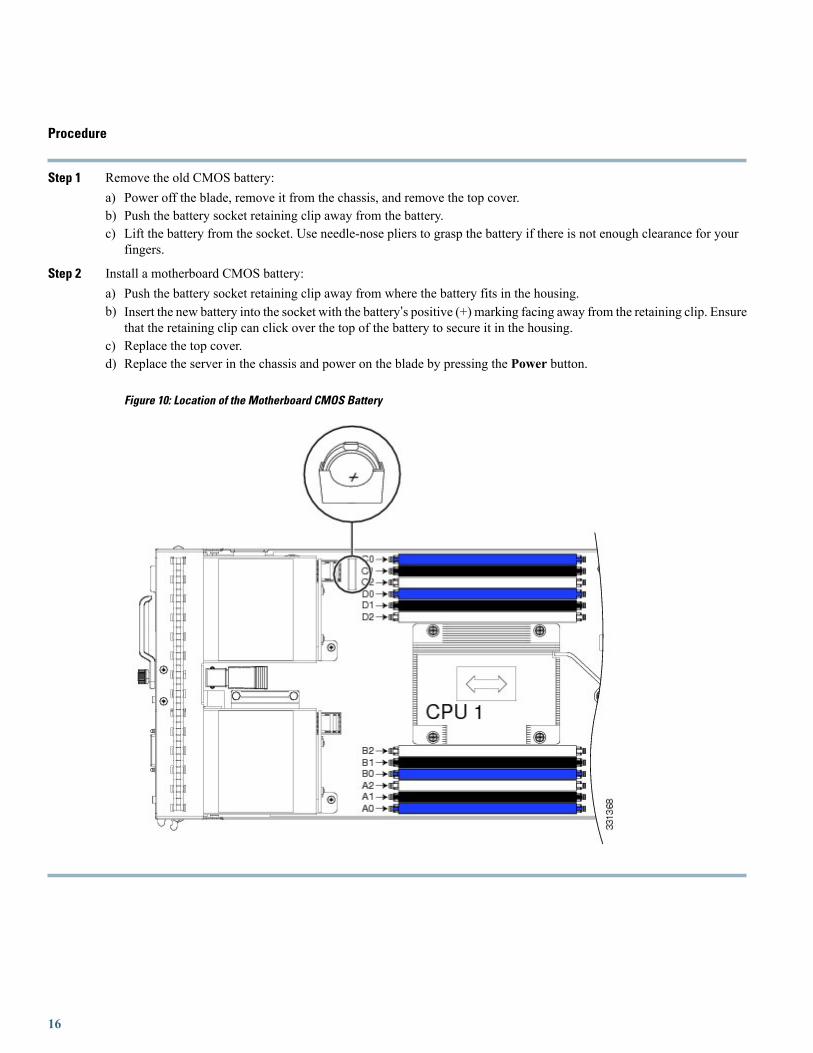
Step 1 Remove the old CMOS battery:a) Power off the blade, remove it from the chassis, and remove the top cover.b) Push the battery socket retaining clip away from the battery.c) Lift the battery from the socket. Use needle-nose pliers to grasp the battery if there is not enough clearance for your
fingers.
Step 2 Install a motherboard CMOS battery:a) Push the battery socket retaining clip away from where the battery fits in the housing.b) Insert the new battery into the socket with the battery’s positive (+) marking facing away from the retaining clip. Ensure
that the retaining clip can click over the top of the battery to secure it in the housing.c) Replace the top cover.d) Replace the server in the chassis and power on the blade by pressing the Power button.
Figure 10: Location of the Motherboard CMOS Battery
16

Removing a CPU and Heat Sink
You will use these procedures to move a CPU from one server to another, to replace a faulty CPU, or to upgrade from one CPU toanother.
The CPU pick and place tool is required to prevent damage to the connection pins between the motherboardand the CPU. Do not attempt this procedure without the required tool, which is included with each CPUoption kit.
Note
To remove a CPU and heat sink, follow these steps:
Procedure
Step 1 Unscrew the four captive screws securing the heat sink to the motherboard. See callout 1.Loosen one screw by a quarter turn, then move to the next in the X pattern shown in Figure 6. Continue loosening untilthe heat sink can be lifted off.
Step 2 Remove the heat sink (UCSB-HS-01-EP). See callout 2.Remove the existing thermal compound from the bottom of the heat sink using the cleaning kit (UCSX-HSCK= ) includedwith each CPU option kit. Follow the instructions on the two bottles of cleaning solvent.
17

Step 3 Unhook the first socket hook, marked with an icon. See callout 3.Step 4 Unhook the second socket hook, marked with an icon. See callout 4.Step 5 Open the socket latch. See callout 5.
Figure 11: Removing the Heat Sink and Accessing the CPU Socket (UCS B200 M3 Server Shown)
Step 6 Press the central button on the provided CPU pick and place tool (UCS-CPU-EP-PNP=) to release the catch.The CPU pick and place tool is included with each CPU option kit, or the tool may be purchased separately. Be sure touse the tool for the Intel Xeon E5-2600 Series processors.
Step 7 Remove an old CPU as follows:a) Place the CPU pick and place tool on the CPU socket aligned with the arrow pointing to the CPU registration mark as
shown in Figure 2.b) Press the button/handle on the tool to grasp the installed CPU.
18

c) Lift the tool and CPU straight up.
Figure 12: Proper Alignment of CPU Pick and Place Tool (for Intel Xeon E5-2600 Series Processors)
Alignment mark on the socket2Alignment mark on the button/handle of the pick andplace tool
1
Installing a New CPU and Heat Sink
Before installing a new CPU in a server, verify the following:
• The CPU is supported for that given server model. This may be verified via the server's Technical Specifications ordering guidesor by the relevant release of the Cisco UCS Capability Catalog.
• A BIOS update is available and installed that supports the CPU and the given server configuration.
• If the server will be managed by Cisco UCS Manager, the service profile for this server in UCS Manager will recognize andallow the new CPU.
19
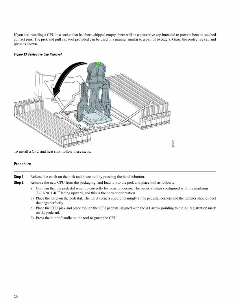
If you are installing a CPU in a socket that had been shipped empty, there will be a protective cap intended to prevent bent or touchedcontact pins. The pick and pull cap tool provided can be used in a manner similar to a pair of tweezers. Grasp the protective cap andpivot as shown.
Figure 13: Protective Cap Removal
To install a CPU and heat sink, follow these steps:
Procedure
Step 1 Release the catch on the pick and place tool by pressing the handle/button.Step 2 Remove the new CPU from the packaging, and load it into the pick and place tool as follows:
a) Confirm that the pedestal is set up correctly for your processor. The pedestal ships configured with the markings“LGA2011-R0” facing upward, and this is the correct orientation.
b) Place the CPU on the pedestal. The CPU corners should fit snugly at the pedestal corners and the notches should meetthe pegs perfectly.
c) Place the CPU pick and place tool on the CPU pedestal aligned with the A1 arrow pointing to the A1 registration markon the pedestal.
d) Press the button/handle on the tool to grasp the CPU.
20
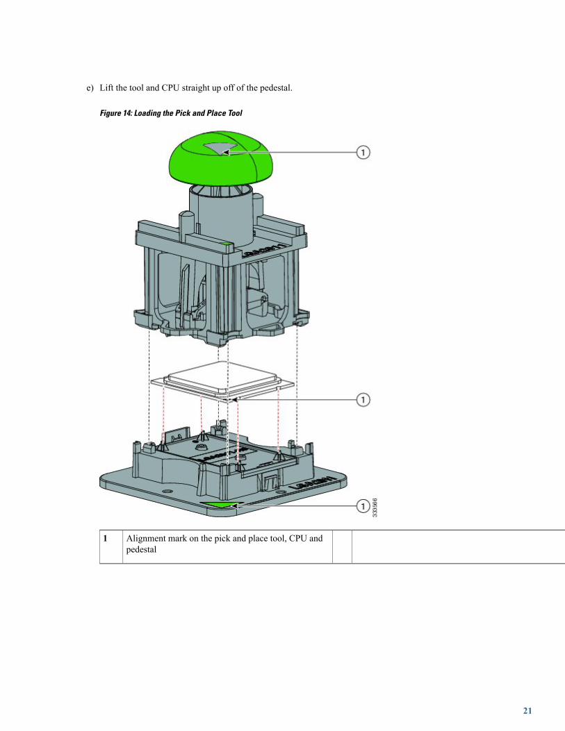
e) Lift the tool and CPU straight up off of the pedestal.
Figure 14: Loading the Pick and Place Tool
Alignment mark on the pick and place tool, CPU andpedestal
1
21
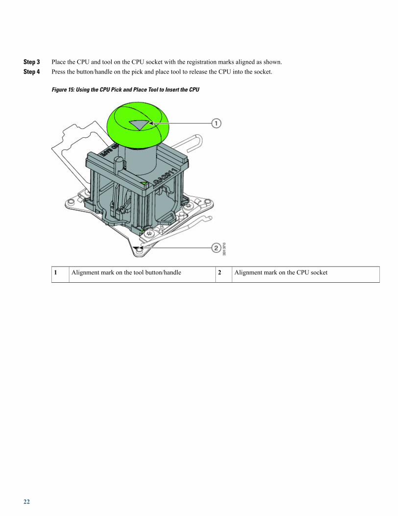
Step 3 Place the CPU and tool on the CPU socket with the registration marks aligned as shown.Step 4 Press the button/handle on the pick and place tool to release the CPU into the socket.
Figure 15: Using the CPU Pick and Place Tool to Insert the CPU
Alignment mark on the CPU socket2Alignment mark on the tool button/handle1
22

Step 5 Close the socket latch. See callout 1 below.Step 6 Secure the first hook, marked with an icon. See callout 2 below.Step 7 Secure the second hook, marked with an icon. See callout 3 below.
Figure 16: Replacing the Heat Sink (B200 M3 Shown)
Step 8 Using the syringe of thermal grease provided with replacement CPUs and servers (and available separately asUCS-CPU-GREASE=, the only exceptions are CiscoUCSC220M3 andC240M3 serverswhich useUCS-CPU-GREASE2=
23

instead), add 2 cubic centimeters of thermal grease to the top of the CPUwhere it will contact the heat sink. Use the patternshown. This should require half the contents of the syringe.
Figure 17: Thermal Grease Application Pattern
The thermal grease has very specific thermal properties, and thermal grease from other sources should not besubstituted. Using other thermal grease may lead to damage.
Caution
Step 9 Replace the heat sink. See callout 4.On certain models, heat sinks are keyed to fit into the plastic baffle extending from the motherboard. Do notforce a heat sink if it is not fitting well, rotate it and re-orient the heat sink.
Caution
Step 10 Secure the heat sink to the motherboard by tightening the four captive screws a quarter turn at a time in an X pattern asshown in the upper right.
Memory and Performance
Installing Memory
24

To install a DIMM into the blade server, follow these steps:
Procedure
Step 1 Open both DIMM connector latches.
Figure 18: Installing DIMMs in the Blade Server
Step 2 Press the DIMM into its slot evenly on both ends until it clicks into place.DIMMs are keyed, if a gentle force is not sufficient, make sure the notch on the DIMM is correctly aligned.
Be sure that the notch in the DIMM aligns with the slot. If the notch is misaligned you may damage the DIMM,the slot, or both.
Note
Step 3 Press the DIMM connector latches inward slightly to seat them fully.
Supported DIMMsThe DIMMs supported in this blade server are constantly being updated. A list of currently supported and available drives is in thespecification sheets at:
http://www.cisco.com/en/US/products/ps10280/products_data_sheets_list.htmlCisco does not support third-party memory DIMMs, and in some cases their use may irreparably damage the server and require anRMA and down time.
Memory Arrangement
25

The blade server contains 24 DIMM slots—12 for each CPU. Each set of 12 DIMM slots is arranged into four channels, where eachchannel has three DIMMs.
Figure 19: Memory Slots within the Blade Server
Channels E-H for CPU 22Channels A-D for CPU 11
DIMMs and ChannelsEach channel is identified by a letter—A, B, C, D for CPU1, and E, F, G, H for CPU 2. Each DIMM slot is numbered 0, 1, or 2. Notethat each DIMM slot 0 is blue, each slot 1 is black, and each slot 2 is off-white or beige.
The figure below shows how DIMMs and channels are physically laid out on the blade server. The DIMM slots in the upper andlower right are associated with the second CPU (CPU shown on right in the diagram), while the DIMM slots in the upper and lowerleft are associated with the first CPU (CPU shown on left).
Figure 20: Physical Representation of DIMMs and Channels
26

The figure below shows a logical view of the DIMMs and channels.
Figure 21: Logical Representation of DIMMs and Channels
DIMMs can be used in the blade server in a one DIMM per Channel (1DPC) configuration, in a two DIMMs per Channel (2DPC)configuration, or a three DIMMs per Channel (3DPC) configuration.
Each CPU in a Cisco UCS B200 M3 blade server supports four channels of three memory slots each. In a 1 DPC configuration,DIMMs are in slot 0 only. In a 2 DPC configuration, DIMMs are in both slot 0 and slot 1. In a 3 DPC configuration, DIMMs are inslot 0, slot 1, and slot 2.
27

Table 2: Supported DIMM Population Order
CPU 2 installed slotsCPU 1 installed slotsDIMMs per CPU
E0A01
E0, F0A0, B02
E0, F0, G0A0, B0, C03
E0, F0, G0, H0A0, B0, C0, D04 (Blue slots)
E0, F0, G0, H0, E1A0, B0, C0, D0, A15
E0, F0, G0, H0, E1, F1A0, B0, C0, D0, A1, B16
E0, F0, G0, H0, E1, F1, G1A0, B0, C0, D0, A1, B1, C17
E0, F0, G0, H0, E1, F1, G1, H1A0, B0, C0, D0, A1, B1, C1, D18 (Blue and black slots)
E0, F0, G0, H0, E1, F1, G1, H1, E2A0, B0, C0, D0, A1, B1, C1, D1,A29
E0, F0, G0, H0, E1, F1, G1, H1, E2, F2A0, B0, C0, D0, A1, B1, C1, D1,A2, B210
E0, F0, G0, H0?E1, F1, G1, H1, E2, F2,G2
A0, B0, C0, D0, A1, B1, C1, D1,A2, B2, C211
E0, F0, G0, H0, E1, F1, G1, H1, E2, F2,G2, H2
A0, B0, C0, D0?A1, B1, C1, D1,A2, B2, C2,D2
12 (Blue, black and beige slots)
Memory PerformanceWhen considering the memory configuration of your blade server, there are several things you need to consider. For example:
•When mixing DIMMs of different densities, the highest density DIMM goes in slot 0 then in descending density (ex: A0:UCS-MR-1X162RY-A , A1: UCS-MR-1X082RY-A, A2: UCS-MR-1X041RY-A)
• Your selected CPU(s) can have some affect on performance.
• DIMMs can be run in a 1DPC, a 2DPC, or a 3DPC configuration. 1 DPC and 2DPC can provide the maximum rated speed thatthe CPU and DIMMs are rated for. 3DPC causes the DIMMs to run at a slower speed.
Memory Mirroring and RASThe Intel E5-2600 CPUs within the blade server support memory mirroring only when an even number of Channels are populatedwith DIMMs. If one or three channels are populated with DIMMs, memory mirroring is automatically disabled. Furthermore, ifmemory mirroring is used, DRAM size is reduced by 50 percent for reasons of reliability.
Installing a Modular LOM
The Cisco VIC 1240 is a specialized modular Lan on Motherboard (mLOM) adapter that provides dual 2 x 10 Gb of Ethernet/ orFiber Channel over Ethernet (FCoE) connectivity to each chassis. It plugs into the dedicated mLOM connector only. It is currently
28
the only card that can be plugged into the mLOM connector and it will provide connectivity through either a 2100 series or 2200series IOM.
You must remove the adapter card to service the modular LOM.Note
To install an mLOM on the blade server, follow these steps:
Procedure
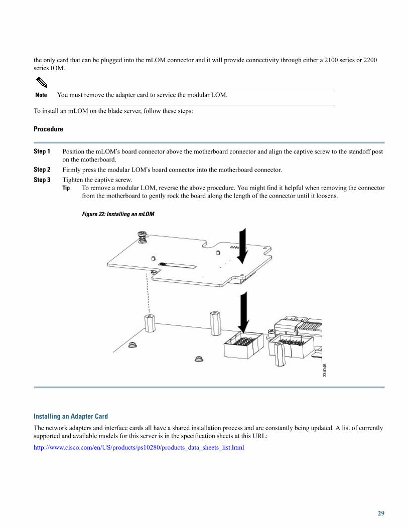
Step 1 Position the mLOM’s board connector above the motherboard connector and align the captive screw to the standoff poston the motherboard.
Step 2 Firmly press the modular LOM’s board connector into the motherboard connector.Step 3 Tighten the captive screw.
To remove a modular LOM, reverse the above procedure. You might find it helpful when removing the connectorfrom the motherboard to gently rock the board along the length of the connector until it loosens.
Figure 22: Installing an mLOM
Tip
Installing an Adapter Card
The network adapters and interface cards all have a shared installation process and are constantly being updated. A list of currentlysupported and available models for this server is in the specification sheets at this URL:
http://www.cisco.com/en/US/products/ps10280/products_data_sheets_list.html
29

If a VIC 1240 mLOM is not installed, you must have an adapter card installed.Note
Use of the adapters available for this server might require an upgrade to the FEX in the chassis. The2104XP FEX is not compatible with any Cisco-certified adapter. If a VIC 1240 mLOM card is installed,you will have connectivity through the mLOM but other adapters will not be recognized. Use of all slotsrequires Cisco UCS 2200 series FEXes.
Note
If you are switching from one type of adapter card to another, before you physically perform the switch make sure that you downloadthe latest device drivers and load them into the server’s operating system. For more information, see the firmware management chapterof one of the Cisco UCS Manager software configuration guides.
The Cisco UCS 785GB or 365GB MLC Fusion-io Drive and LSI 400GB SLC WarpDrive have the same form factor as M3 adaptercards and can be installed and removed using the same procedures. Using these drives in a B200 M3 or B22 M3 blade server requiresthe presence of a VIC 1240 mLOM to provide blade I/O. They will not work in M1 and M2 generation Cisco UCS servers. Thesedrives appear in Cisco UCS Manager as regular SSDs.
Procedure
Step 1 Position the adapter board connector above the motherboard connector and align the two adapter captive screws to thestandoff posts (see callout 1) on the motherboard.
Step 2 Firmly press the adapter connector into the motherboard connector (see callout 2) .Step 3 Tighten the two captive screws (see callout 3) .
30

Removing an adapter card is the reverse of installing it. You might find it helpful when removing the connectorfrom the motherboard to gently rock the board along the length of the connector until it loosens.
Tip
Figure 23: Installing an Adapter Card
Enabling a Trusted Platform ModuleThe Trusted Platform Module (TPM, Cisco Product ID UCSX-TPM1-001) is a component that can securely store artifacts used toauthenticate the server. These artifacts can include passwords, certificates, or encryption keys. A TPM can also be used to storeplatform measurements that help ensure that the platform remains trustworthy. Authentication (ensuring that the platform can provethat it is what it claims to be) and attestation (a process helping to prove that a platform is trustworthy and has not been breached)are necessary steps to ensure safer computing in all environments.
A TPM is a factory-configurable option for this server. It is a requirement for the Intel Trusted Execution Technology (TXT) securityfeature, which must be enabled in the BIOS settings for a server equipped with a TPM. A TPM can not be added later by customers,or moved from one server to another.
To enable the TPM:
31

Procedure
Step 1 Enable Quiet Mode in the BIOS policy of the server’s Service Profile.Step 2 Establish a direct connection to the server, either by connecting a keyboard, monitor, and mouse to the front panel using
a KVM dongle (N20-BKVM) or by other means.Step 3 Reboot the server.Step 4 Press F2 during reboot to enter the BIOS setup screens.Step 5 On the Advanced tab, select Trusted Computing and press Enter.Step 6 Set the TPM Support option to Enable.Step 7 Press F10 to save and exit. Allow the server to finish booting.
Server TroubleshootingFor general server troubleshooting information, refer to the Troubleshooting Server Hardware chapter of the CiscoUCSTroubleshootingGuide.
Server ConfigurationUCS blade servers are intended to be configured and managed using UCS Manager. Refer to the UCS Manager Configuration Guideappropriate for your UCS Manager version.
Server Specifications
Table 3: Physical Specifications for the Cisco UCS B200 M3 Blade Server
ValueSpecification
1.95 inches (50 mm)Height
8.00 inches (203 mm)Width
24.4 inches (620 mm)Depth
15.0 lbs (6.8 kg) 3Weight
3 The system weight listed here is an estimate for a fully configured system and will vary depending on peripheral devices installed.
32
Revised: June 13, 2013, OL-26624-01
Related DocumentationThe documentation set for the Cisco Unified Computing System environment is described in full at:
http://www.cisco.com/go/unifiedcomputing/b-series-doc
For specifics on which component models are supported on which servers refer to the server's Technical Specifications orderingguide at:
http://www.cisco.com/en/US/products/ps10493/products_data_sheets_list.html

Revised: June 13, 2013, OL-26624-01
Obtaining Documentation and Submitting a Service RequestFor information on obtaining documentation, submitting a service request, and gathering additional information, see the monthlyWhat's New in Cisco Product Documentation, which also lists all new and revised Cisco technical documentation.
Subscribe to theWhat's New in Cisco Product Documentation as a Really Simple Syndication (RSS) feed and set content to bedelivered directly to your desktop using a reader application. The RSS feeds are a free service and Cisco currently supports RSSversion 2.0.
Follow Cisco UCS Docs on Twitter to receive document update notifications.
34

© 2012 Cisco Systems, Inc. All rights reserved.
Europe HeadquartersAsia Pacific HeadquartersAmericas HeadquartersCisco Systems International BVAmsterdam, The Netherlands
Cisco Systems (USA) Pte. Ltd.Singapore
Cisco Systems, Inc.San Jose, CA 95134-1706USA
Cisco has more than 200 offices worldwide. Addresses, phone numbers, and fax numbers are listed on theCisco Website at www.cisco.com/go/offices.