Cisco Ssg20
86
Juniper Networks, Inc. 1194 North Mathilda Avenue Sunnyvale, CA 94089 USA 408-745-2000 www.juniper.net Part Number: 530-015646-01, Revision 03 Security Products SSG 20 Hardware Installation and Configuration Guide
-
Upload
albarkhairan -
Category
Documents
-
view
243 -
download
0
Transcript of Cisco Ssg20

8/3/2019 Cisco Ssg20
http://slidepdf.com/reader/full/cisco-ssg20 1/86
Juniper Networks, Inc.
1194 North Mathilda Avenue
Sunnyvale, CA 94089
USA
408-745-2000
www.juniper.net
Part Number: 530-015646-01, Revision 03
Security Products
SSG 20 Hardware Installation and Configuration Guide
8/3/2019 Cisco Ssg20
http://slidepdf.com/reader/full/cisco-ssg20 2/86
2
Copyright Notice
Copyright © 2006 Juniper Networks, Inc. All rights reserved.
Juniper Networks and the Juniper Networks logo are registered trademarks of Juniper Networks, Inc. in the United States and other countries. All othertrademarks, service marks, registered trademarks, or registered service marks in this document are the property of Juniper Networks or their respective
owners. All specifications are subject to change without notice. Juniper Networks assumes no responsibility for any inaccuracies in this document or forany obligation to update information in this document. Juniper Networks reserves the right to change, modify, transfer, or otherwise revise this publicationwithout notice.
FCC Statement
The following information is for FCC compliance of Class A devices: This equipment has been tested and found to comply with the limits for a Class Adigital device, pursuant to part 15 of the FCC rules. These limits are designed to provide reasonable protection against harmful interference when theequipment is operated in a commercial environment. The equipment generates, uses, and can radiate radio-frequency energy and, if not installed andused in accordance with the instruction manual, may cause harmful interference to radio communications. Operation of this equipment in a residentialarea is likely to cause harmful interference, in which case users will be required to correct the interference at their own expense.
The following information is for FCC compliance of Class B devices: The equipment described in this manual generates and may radiate radio-frequencyenergy. If it is not installed in accordance with Juniper Networks’ installation instructions, it may cause interference with radio and television reception.This equipment has been tested and found to comply with the limits for a C lass B digital device in accordance with the specifications in part 15 of the FCCrules. These specifications are designed to provide reasonable protection against such interference in a residential installation. However, there is noguarantee that interference will not occur in a particular installation.
If this equipment does cause harmful interference to radio or television reception, which can be determined by turning the equipment off and on, the useris encouraged to try to correct the interference by one or more of the following measures:
Reorient or relocate the receiving antenna.
Increase the separation between the equipment and receiver.
Consult the dealer or an experienced radio/TV technician for help.
Connect the equipment to an outlet on a circuit different from that to which the receiver is connected.
Caution: Changes or modifications to this product could void the user's warranty and authority to operate this device.
Disclaimer
THE SOFTWARE LICENSE AND LIMITED WARRANTY FOR THE ACCOMPANYING PRODUCT ARE SET FORTH IN THE INFORMATION PACKET THAT SHIPPEDWITH THE PRODUCT AND ARE INCORPORATED HEREIN BY THIS REFERENCE. IF YOU ARE UNABLE TO LOCATE THE SOFTWARE LICENSE OR LIMITEDWARRANTY, CONTACT YOUR JUNIPER NETWORKS REPRESENTATIVE FOR A COPY.
8/3/2019 Cisco Ssg20
http://slidepdf.com/reader/full/cisco-ssg20 3/86
Table of Contents 3
Table of Contents
About This Guide 5
Organization....................................................................................................6WebUI Conventions .........................................................................................6CLI Conventions...............................................................................................7Obtaining Documentation and Technical Support............................................8
Chapter 1 Hardware Overview 9
Port and Power Connectors ...........................................................................10Front Panel ....................................................................................................11
System Status LEDs.................................................................................11Port Descriptions.....................................................................................13
Ethernet Ports...................................................................................13Console Port .....................................................................................13AUX Port...........................................................................................14
Mini Physical Interface Module Port Descriptions....................................14Back Panel .....................................................................................................16
Power Adapter.........................................................................................16Radio Transceivers ..................................................................................16Grounding Lug.........................................................................................17
Antennae Types.......................................................................................18USB Port..................................................................................................18
Chapter 2 Installing and Connecting the Device 19
Before You Begin ...........................................................................................20Installing Equipment ......................................................................................20Connecting Interface Cables to a Device ........................................................22Connecting the Power....................................................................................22Connecting a Device to a Network.................................................................23
Connecting a Device to an Untrusted Network ........................................23Ethernet Ports...................................................................................24Serial (AUX/Console) Ports ................................................................24
Connecting Mini PIMs to an Untrusted Network ......................................24ADSL2/2+ Mini PIM .........................................................................24ISDN, T1, E1, and V.92 Mini PIMs.....................................................25
Connecting a Device to an Internal Network or a Workstation ................25Ethernet Ports...................................................................................25Wireless Antennae ............................................................................26
Chapter 3 Configuring the Device 27
Accessing a Device.........................................................................................28Using a Console Connection ....................................................................28Using the WebUI .....................................................................................29
8/3/2019 Cisco Ssg20
http://slidepdf.com/reader/full/cisco-ssg20 4/86
4 Table of Contents
SSG 20 Hardware Installation and Configuration Guide
Using Telnet ............................................................................................30Default Device Settings ..................................................................................31Basic Device Configuration ............................................................................33
Root Admin Name and Password ............................................................33Date and Time.........................................................................................34Bridge Group Interfaces...........................................................................34Administrative Access .............................................................................35Management Services..............................................................................35Hostname and Domain Name .................................................................36Default Route...........................................................................................36Management Interface Address ...............................................................36Backup Untrust Interface Configuration...................................................37
Basic Wireless Configuration..........................................................................37Mini PIM Configuration ..................................................................................41
ADSL2/2+ Interface ................................................................................41Virtual Circuits ..................................................................................42VPI/VCI and Multiplexing Method......................................................42
PPPoE or PPPoA ...............................................................................43Static IP Address and Netmask..........................................................44
ISDN Interface .........................................................................................45T1 Interface.............................................................................................45E1 Interface.............................................................................................46V.92 Modem Interface.............................................................................47
Basic Firewall Protections ..............................................................................48Verifying External Connectivity......................................................................48Resetting a Device to Factory Defaults ...........................................................49
Chapter 4 Servicing the Device 51
Required Tools and Parts ...............................................................................51Replacing a Mini-Physical Interface Module ...................................................51
Removing a Blank Faceplate....................................................................52Removing a Mini PIM ..............................................................................52Installing a Mini PIM................................................................................53
Upgrading Memory........................................................................................54
Appendix A Specifications 57
Physical..........................................................................................................58Electrical ........................................................................................................58Environmental Tolerance...............................................................................58Certifications..................................................................................................59
Safety ......................................................................................................59EMC Emissions........................................................................................59
EMC Immunity ........................................................................................59ETSI.........................................................................................................59T1 Interface.............................................................................................60
Connectors.....................................................................................................60
Appendix B Initial Configuration Wizard 63
Index.......................................................................................................................... 85

8/3/2019 Cisco Ssg20
http://slidepdf.com/reader/full/cisco-ssg20 5/86
5
About This Guide
The Juniper Networks Secure Services Gateway (SSG) 20 device is an integratedrouter and firewall platform that provides Internet Protocol Security (IPSec) virtualprivate network (VPN) and firewall services for a branch office or a retail outlet.
Juniper Networks offers two models of the SSG 20 device:
SSG 20, which supports auxiliary (AUX) connectivity
SSG 20-WLAN, which supports integrated 802.11a/b/g wireless standards
Both SSG 20 devices support universal serial bus (USB) storage and two miniphysical interface module (PIM) slots that can hold any of the mini PIMs. Thedevices also provide protocol conversions between local area networks (LANs) andwide area networks (WANs).
NOTE: The configuration instructions and examples in this document are based on thefunctionality of a device running ScreenOS 5.4. Your device might functiondifferently depending on the ScreenOS version you are running. For the latest
device documentation, refer to the Juniper Networks Technical Publicationswebsite at http://www.juniper.net/techpubs/hardware. To see which ScreenOSversions are currently available for your device, refer to the Juniper NetworksSupport website at http://www.juniper.net/customers/support/.
8/3/2019 Cisco Ssg20
http://slidepdf.com/reader/full/cisco-ssg20 6/86
SSG 20 Hardware Installation and Configuration Guide
6 Organization
Organization
This guide contains the following sections:
Chapter 1, “Hardware Overview,” describes the chassis and components of anSSG 20 device.
Chapter 2, “Installing and Connecting the Device,” describes how to mount anSSG 20 device and how to connect cables and power to the device.
Chapter 3, “Configuring the Device,” describes how to configure and managean SSG 20 device and how to perform some basic configuration tasks.
Chapter 4, “Servicing the Device,” describes service and maintenanceprocedures for the SSG 20 device.
Appendix A, “Specifications,” provides general system specifications for the
SSG 20 device.
Appendix B, “Initial Configuration Wizard,” provides detailed information aboutusing the Initial configuration Wizard (ICW) for an SSG 20 device.
WebUI Conventions
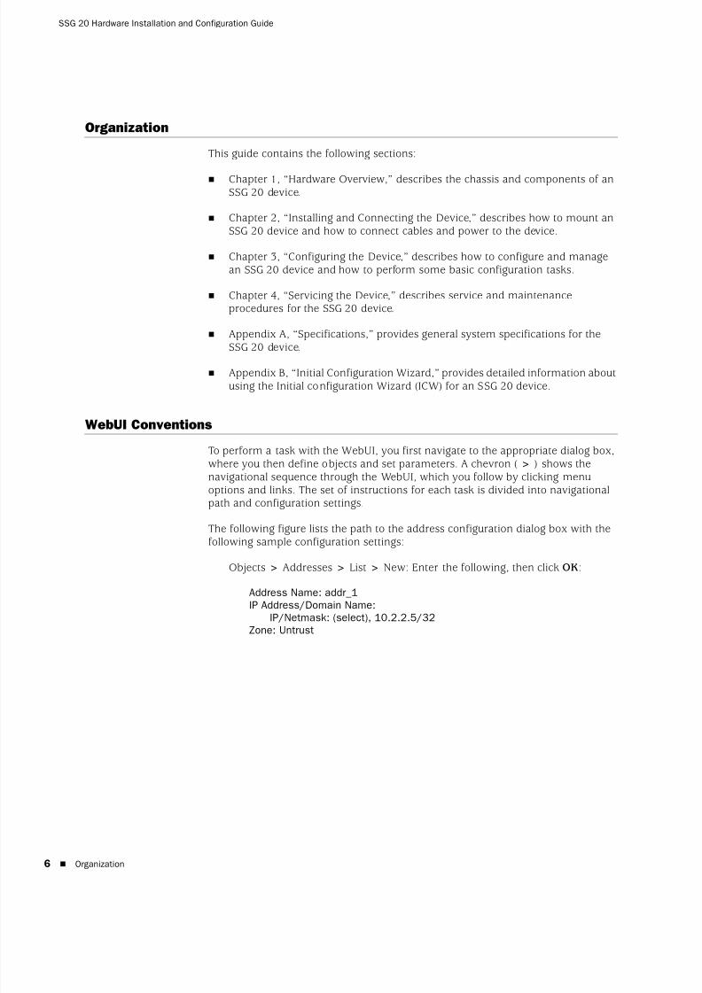
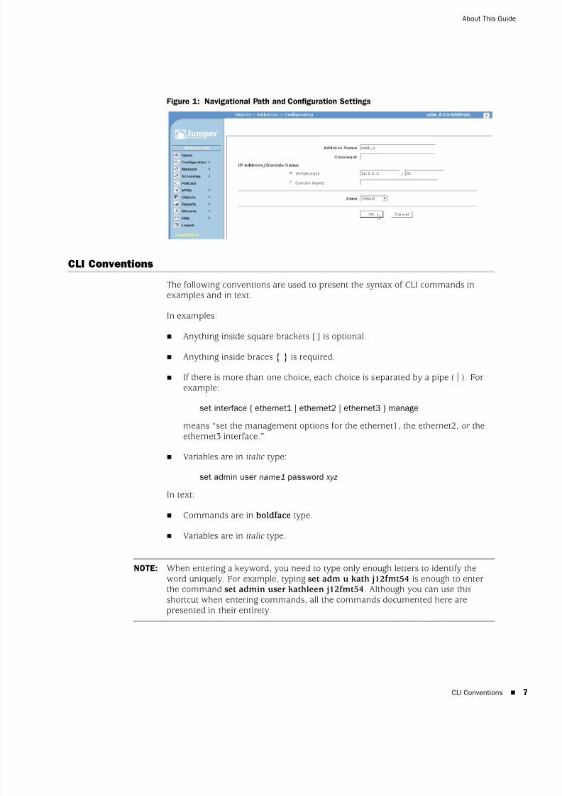
To perform a task with the WebUI, you first navigate to the appropriate dialog box,where you then define objects and set parameters. A chevron ( > ) shows thenavigational sequence through the WebUI, which you follow by clicking menuoptions and links. The set of instructions for each task is divided into navigationalpath and configuration settings.
The following figure lists the path to the address configuration dialog box with thefollowing sample configuration settings:
Objects > Addresses > List > New: Enter the following, then click OK:
Address Name: addr_1IP Address/Domain Name:
IP/Netmask: (select), 10.2.2.5/32Zone: Untrust
8/3/2019 Cisco Ssg20
http://slidepdf.com/reader/full/cisco-ssg20 7/86
CLI Conventions 7
About This Guide
Figure 1: Navigational Path and Configuration Settings
CLI Conventions
The following conventions are used to present the syntax of CLI commands inexamples and in text.
In examples:
Anything inside square brackets [ ] is optional.
Anything inside braces { } is required.
If there is more than one choice, each choice is separated by a pipe ( | ). Forexample:
set interface { ethernet1 | ethernet2 | ethernet3 } manage
means “set the management options for the ethernet1, the ethernet2, or theethernet3 interface.”
Variables are in italic type:
set admin user name1 password xyz
In text:
Commands are in boldface type.
Variables are in italic type.
NOTE: When entering a keyword, you need to type only enough letters to identify theword uniquely. For example, typing set adm u kath j12fmt54 is enough to enterthe command set admin user kathleen j12fmt54. Although you can use thisshortcut when entering commands, all the commands documented here arepresented in their entirety.

8/3/2019 Cisco Ssg20
http://slidepdf.com/reader/full/cisco-ssg20 8/86
SSG 20 Hardware Installation and Configuration Guide
8 Obtaining Documentation and Technical Support
Obtaining Documentation and Technical Support
To obtain technical documentation for any Juniper Networks product, visitwww.juniper.net/techpubs/ .
For technical support, open a support case using the Case Manager link athttp://www.juniper.net/support/ or call 1-888-314-JTAC (within the United States) or1-408-745-9500 (outside the United States).
If you find any errors or omissions in this document, please contact us at thefollowing email address:

8/3/2019 Cisco Ssg20
http://slidepdf.com/reader/full/cisco-ssg20 9/86
9
Chapter 1
Hardware Overview
This chapter provides detailed descriptions of the SSG 20 chassis and itscomponents. It contains the following sections:
“Port and Power Connectors” on page 10
“Front Panel” on page 11
“Back Panel” on page 16
8/3/2019 Cisco Ssg20
http://slidepdf.com/reader/full/cisco-ssg20 10/86
SSG 20 Hardware Installation and Configuration Guide
10 Port and Power Connectors
Port and Power Connectors
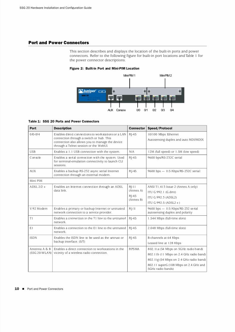
This section describes and displays the location of the built-in ports and powerconnectors. Refer to the following figure for built-in port locations and Table 1 forthe power connector descriptions.
Figure 2: Built-in Port and Mini-PIM Location
Table 1: SSG 20 Ports and Power Connectors
AUX 0/0
10 /100AUX
0/0 10/100 0/0 10/100 0/0 10 /100 0/0 10 /100
LINK
STATUS
POWER
PIM 2
PIM 1
b/g
802.11a
WLAN
SSG 20
1 2
Mini-PIM 2Mini-PIM 1
AUX Console 0/0 0/1 0/2 0/3 0/4
Port Description Connector Speed/Protocol
0/0-0/4 Enables direct connections to workstations or a LANconnection through a switch or hub. Thisconnection also allows you to manage the devicethrough a Telnet session or the WebUI.
RJ-45 10/100 Mbps Ethernet
Autosensing duplex and auto MDI/MDIX
USB Enables a 1.1 USB connection with the system. N/A 12M (full speed) or 1.5M (low speed)
Console Enables a serial connection with the system. Usedfor terminal-emulation connectivity to launch CLIsessions.
RJ-45 9600 bps/RS-232C serial
AUX Enables a backup RS-232 async serial Internet
connection through an external modem.
RJ-45 9600 bps — 115 Kbps/RS-232C serial
Mini PIM
ADSL 2/2+ Enables an Internet connection through an ADSLdata link.
RJ-11(Annex A)
RJ-45(Annex B)
ANSI T1.413 Issue 2 (Annex A only)
ITU G.992.1 (G.dmt)
ITU G.992.3 (ADSL2)
ITU G.992.5 (ADSL2+)
V.92 Modem Enables a primary or backup Internet or untrustednetwork connection to a service provider.
RJ-11 9600 bps — 115 Kbps/RS-232 serialautosensing duplex and polarity
T1 Enables a connection to the T1 line to the untrustednetwork.
RJ-45 1.544 Mbps (full-time slots)
E1 Enables a connection to the E1 line to the untrusted
network.
RJ-45 2.048 Mbps (full-time slots)
ISDN Enables the ISDN line to be used as the untrust orbackup interface. (S/T)
RJ-45 B-channels at 64 Kbps
Leased line at 128 Kbps
Antenna A & B(SSG 20-WLAN)
Enables a direct connection to workstations in thevicinity of a wireless radio connection.
RPSMA 802.11a (54 Mbps on 5GHz radio band)
802.11b (11 Mbps on 2.4 GHz radio band)
802.11g (54 Mbps on 2.4 GHz radio band)
802.11 superG (108 Mbps on 2.4 GHz and5GHz radio bands)

8/3/2019 Cisco Ssg20
http://slidepdf.com/reader/full/cisco-ssg20 11/86
Front Panel 11
Front Panel
This section describes the following elements on the front panel of an SSG 20device:
System Status LEDs
Port Descriptions
Mini Physical Interface Module Port Descriptions
System Status LEDs
The system status LEDs display information about critical device functions. Figure 3 illustrates the position of each status LED on the front of the SSG 20-WLAN device.The WLAN LEDs are only present on the SSG 20-WLAN device.
Figure 3: Status LEDs
When the system powers up, the POWER LED changes from off to blinking green,and the STATUS LED changes in the following sequence: red, green, blinking green.Startup takes approximately two minutes to complete. If you want to turn thesystem off and on again, we recommend you wait a few seconds between shuttingit down and powering it back up. Table 2 provides the name, color, status, anddescription of each system status LED.
Table 2: Status LED Descriptions
Name Color Status Description
POWER Green On steadily Indicates that the system is receiving power.
Off Indicates that the system is not receivingpower.
Red On steadily Indicates that the device is not operatingnormally.
Off Indicates that the device is operatingnormally.
STATUS Green On steadily Indicates that the system is starting orperforming diagnostics.
Blinking Indicates that the device is operatingnormally.
Red Blinking Indicates that there is an error detected.
PIM 1 Green On steadily Indicates that the mini PIM is functioning.
Blinking Indicates that the mini PIM is passing traffic.
Off Indicates that the mini PIM is notoperational.
STATUS
POWER
PIM 2
PIM 1
b/g
802.11a
WLAN
1 2
8/3/2019 Cisco Ssg20
http://slidepdf.com/reader/full/cisco-ssg20 12/86
SSG 20 Hardware Installation and Configuration Guide
12 Front Panel
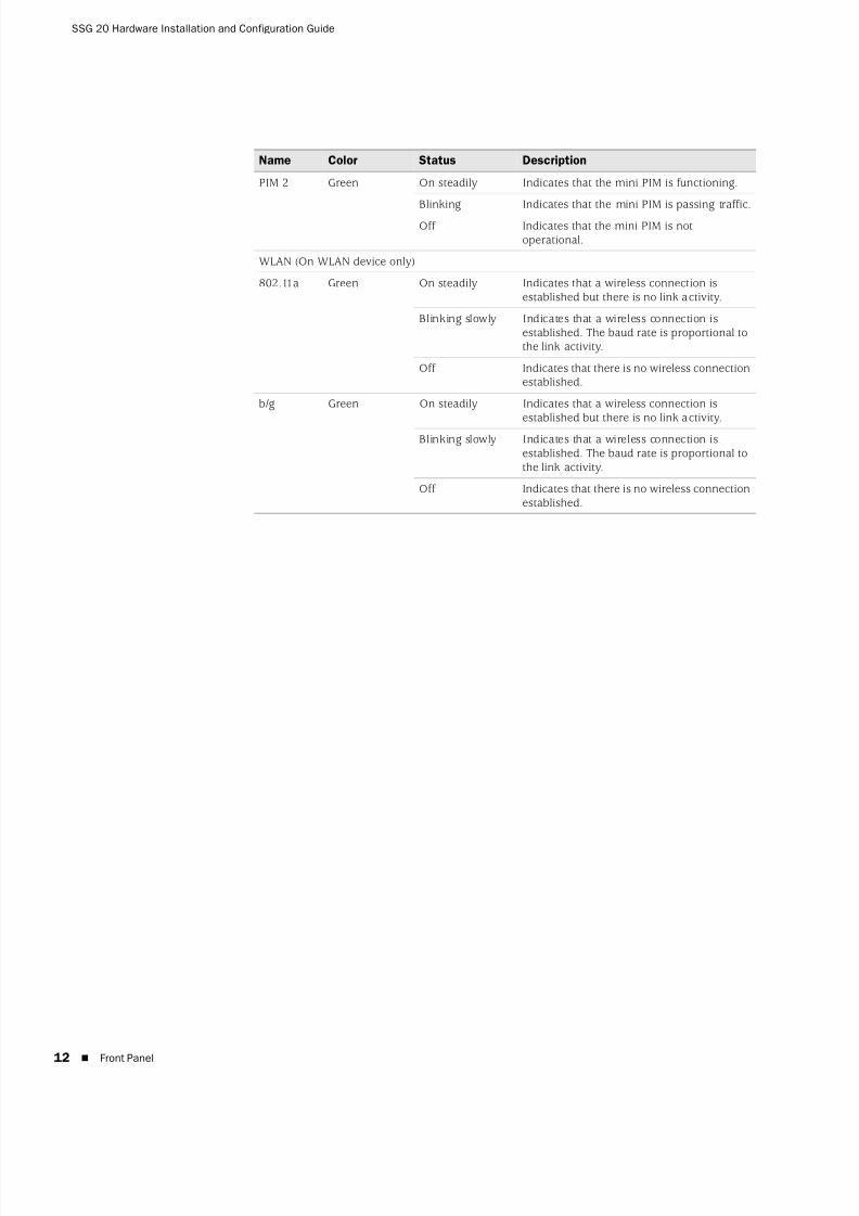
PIM 2 Green On steadily Indicates that the mini PIM is functioning.
Blinking Indicates that the mini PIM is passing traffic.
Off Indicates that the mini PIM is notoperational.
WLAN (On WLAN device only)
802.11a Green On steadily Indicates that a wireless connection isestablished but there is no link activity.
Blinking slowly Indicates that a wireless connection isestablished. The baud rate is proportional tothe link activity.
Off Indicates that there is no wireless connectionestablished.
b/g Green On steadily Indicates that a wireless connection isestablished but there is no link activity.
Blinking slowly Indicates that a wireless connection isestablished. The baud rate is proportional tothe link activity.
Off Indicates that there is no wireless connectionestablished.
Name Color Status Description
8/3/2019 Cisco Ssg20
http://slidepdf.com/reader/full/cisco-ssg20 13/86
Front Panel 13
Port Descriptions
This section explains the purpose and function of the following:
Ethernet Ports
Console Port
AUX Port
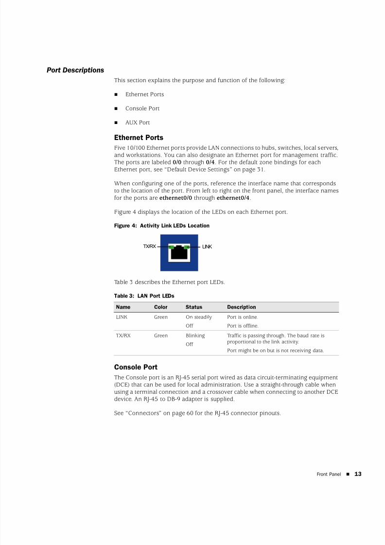
Ethernet Ports
Five 10/100 Ethernet ports provide LAN connections to hubs, switches, local servers,and workstations. You can also designate an Ethernet port for management traffic.The ports are labeled 0/0 through 0/4. For the default zone bindings for eachEthernet port, see “Default Device Settings” on page 31.
When configuring one of the ports, reference the interface name that corresponds
to the location of the port. From left to right on the front panel, the interface namesfor the ports are ethernet0/0 through ethernet0/4.
Figure 4 displays the location of the LEDs on each Ethernet port.
Figure 4: Activity Link LEDs Location
Table 3 describes the Ethernet port LEDs.
Table 3: LAN Port LEDs
Console Port
The Console port is an RJ-45 serial port wired as data circuit-terminating equipment(DCE) that can be used for local administration. Use a straight-through cable whenusing a terminal connection and a crossover cable when connecting to another DCEdevice. An RJ-45 to DB-9 adapter is supplied.
See “Connectors” on page 60 for the RJ-45 connector pinouts.
Name Color Status Description
LINK Green On steadily
Off
Port is online.
Port is offline.
TX/RX Green Blinking
Off
Traffic is passing through. The baud rate isproportional to the link activity.
Port might be on but is not receiving data.
LINKTX/RX
8/3/2019 Cisco Ssg20
http://slidepdf.com/reader/full/cisco-ssg20 14/86
SSG 20 Hardware Installation and Configuration Guide
14 Front Panel
AUX Port
The auxiliary (AUX) port is an RJ-45 serial port wired as data terminal equipment(DTE) that can be connected to a modem to allow remote administration. We do not
recommend using this port for regular remote administration. The AUX port istypically assigned to be the backup serial interface. The baud rate is adjustable from9600 bps to 115200 bps and requires hardware flow control. Use a straight-throughcable when connecting to a modem and a crossover cable when connecting toanother DTE device.
See “Connectors” on page 60 for the RJ-45 connector pinouts.
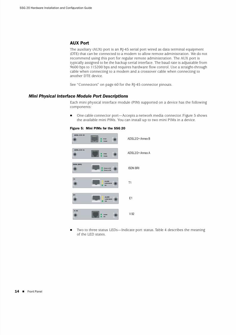
Mini Physical Interface Module Port Descriptions
Each mini physical interface module (PIM) supported on a device has the followingcomponents:
One cable connector port—Accepts a network media connector. Figure 5 showsthe available mini PIMs. You can install up to two mini PIMs in a device.
Figure 5: Mini PIMs for the SSG 20
Two to three status LEDs—Indicate port status. Table 4 describes the meaning
of the LED states.
ISDN BRI
T1
V.92
E1
ADSL2/2+ Annex A
ADSL2/2+ Annex B
ISDN (BRI)
Chann el B2
Chann el B1
V.92
CD
TX/RX
ADSL 2/2+ A
TX/RX
SYNC
T1
CD
LOOP BACK
ALARM
E1
CD
LOOP BACK
ALARM
TX/RX
SYNC
ADSL 2/2+ B
8/3/2019 Cisco Ssg20
http://slidepdf.com/reader/full/cisco-ssg20 15/86
Front Panel 15
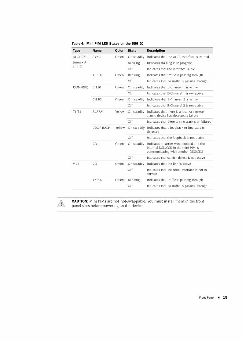
Table 4: Mini PIM LED States on the SSG 20
Type Name Color State Description
ADSL 2/2+
(Annex Aand B)
SYNC Green On steadily Indicates that the ADSL interface is trained
Blinking Indicates training is in progress
Off Indicates that the interface is idle
TX/RX Green Blinking Indicates that traffic is passing through
Off Indicates that no traffic is passing through
ISDN (BRI) CH B1 Green On steadily Indicates that B-Channel 1 is active
Off Indicates that B-Channel 1 is not active
CH B2 Green On steadily Indicates that B-Channel 2 is active
Off Indicates that B-Channel 2 is not active
T1/E1 ALARM Yellow On steadily Indicates that there is a local or remotealarm; device has detected a failure
Off Indicates that there are no alarms or failures
LOOP BACK Yellow On steadily Indicates that a loopback or line state isdetected
Off Indicates that the loopback is not active
CD Green On steadily Indicates a carrier was detected and theinternal DSU/CSU in the mini PIM iscommunicating with another DSU/CSU
Off Indicates that carrier detect is not active
V.92 CD Green On steadily Indicates that the link is active
Off Indicates that the serial interface is not inservice
TX/RX Green Blinking Indicates that traffic is passing throughOff Indicates that no traffic is passing through
CAUTION: Mini PIMs are not hot-swappable. You must install them in the frontpanel slots before powering on the device.
8/3/2019 Cisco Ssg20
http://slidepdf.com/reader/full/cisco-ssg20 16/86
SSG 20 Hardware Installation and Configuration Guide
16 Back Panel
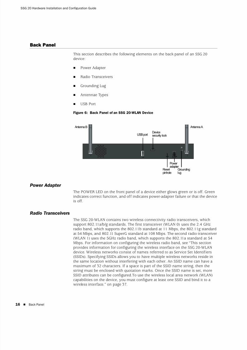
Back Panel
This section describes the following elements on the back panel of an SSG 20device:
Power Adapter
Radio Transceivers
Grounding Lug
Antennae Types
USB Port
Figure 6: Back Panel of an SSG 20-WLAN Device
Power Adapter
The POWER LED on the front panel of a device either glows green or is off. Greenindicates correct function, and off indicates power-adapter failure or that the deviceis off.
Radio Transceivers
The SSG 20-WLAN contains two wireless connectivity radio transceivers, whichsupport 802.11a/b/g standards. The first transceiver (WLAN 0) uses the 2.4 GHzradio band, which supports the 802.11b standard at 11 Mbps, the 802.11g standardat 54 Mbps, and 802.11 SuperG standard at 108 Mbps. The second radio transceiver(WLAN 1) uses the 5GHz radio band, which supports the 802.11a standard at 54Mbps. For information on configuring the wireless radio band, see “This sectionprovides information for configuring the wireless interface on the SSG 20-WLANdevice. Wireless networks consist of names referred to as Service Set Identifiers(SSIDs). Specifying SSIDs allows you to have multiple wireless networks reside inthe same location without interfering with each other. An SSID name can have amaximum of 32 characters. If a space is part of the SSID name string, then thestring must be enclosed with quotation marks. Once the SSID name is set, moreSSID attributes can be configured.To use the wireless local area network (WLAN)capabilities on the device, you must configure at least one SSID and bind it to awireless interface.” on page 37.
B A
LOCK
DC POWER12V A4
RESETUSB
Power adapter
USB port
Groundinglug
Antenna B Antenna A
Resetpinhole
Devicesecurity lock

8/3/2019 Cisco Ssg20
http://slidepdf.com/reader/full/cisco-ssg20 17/86
Back Panel 17
Grounding Lug
A one-hole grounding lug is provided on the rear of the chassis to connect thedevice to earth ground (see Figure 6).
To ground the device before connecting power, connect a grounding cable to earthground and then attach the cable to the lug on the rear of the chassis.

8/3/2019 Cisco Ssg20
http://slidepdf.com/reader/full/cisco-ssg20 18/86
SSG 20 Hardware Installation and Configuration Guide
18 Back Panel
Antennae Types
The SSG 20-WLAN device supports three types of custom-built radio antennae:
Diversity antennae — The diversity antennae provide 2dBi directionalcoverage and a fairly uniform level of signal strength within the area of coverage and are suitable for most installations. This type of antennae isshipped with the device.
External omnidirectional antenna — The external antenna provides 2dBiomnidirectional coverage. Unlike diversity antennae, which function as a pair,an external antenna operates to eliminate an echo effect that can sometimesoccur from slightly delayed characteristics in signal reception when two are inuse.
External directional antenna — The external directional antenna provides2dBi unidirectional coverage and is appropriate for locations like hallways andouter walls (with the antenna facing inward).
USB Port
The USB port on the back panel of an SSG 20 device accepts a universal serial bus(USB) storage device or USB storage device adapter with a compact-flash diskinstalled, as defined in the CompactFlash Specification published by theCompactFlash Association. When the USB storage device is installed andconfigured, it automatically acts as a secondary boot device if the primarycompact-flash disk fails on startup.
The USB port allows file transfers such as device configurations, user certifications,and update version images between an external USB storage device and theinternal flash storage located in the security device. The USB port supports USB 1.1
specification at either low speed (1.5M) or full speed (12M) file transfer.
To transfer files between the USB storage device and an SSG 20, perform thefollowing steps:
1. Insert the USB storage device into the USB port on the security device.
2. Save the files from the USB storage device to the internal flash storage on thedevice with the save {software | config | image-key} from usb filename toflash CLI command.
3. Before removing the USB storage device, stop the USB port with the execusb-device stop CLI command.
4. It is now safe to remove the USB storage device.
If you want to delete a file from the USB storage device, use the delete file usb:/filename CLI command.
If you want to view the saved file information on the USB storage device or internalflash storage, use the get file CLI command.

8/3/2019 Cisco Ssg20
http://slidepdf.com/reader/full/cisco-ssg20 19/86
19
Chapter 2
Installing and Connecting the Device
This chapter describes how to mount an SSG 20 device and connect cables andpower to the device. This chapter contains the following sections:
“Before You Begin” on page 20
“Installing Equipment” on page 20
“Connecting Interface Cables to a Device” on page 22
“Connecting the Power” on page 22
“Connecting a Device to a Network” on page 23
NOTE: For safety warnings and instructions, refer to the Juniper Networks Security Products Safety Guide. Before working on any equipment, you should be aware of the hazards involved with electrical circuitry and be familiar with standard
practices for preventing accidents.
8/3/2019 Cisco Ssg20
http://slidepdf.com/reader/full/cisco-ssg20 20/86
SSG 20 Hardware Installation and Configuration Guide
20 Before You Begin
Before You Begin
The location of the chassis, the layout of the mounting equipment, and the securityof your wiring room are crucial for proper system operation.
Observing the following precautions can prevent shutdowns, equipment failures,and injuries:
Before installation, always check that the power supply is disconnected fromany power source.
Ensure that the room in which you operate the device has adequate air
circulation and that the room temperature does not exceed 104°F (40°C). Do not place the device in an equipment-rack frame that blocks an intake or
exhaust port. Ensure that enclosed racks have fans and louvered sides.
Correct these hazardous conditions before any installation: moist or wet floors,leaks, ungrounded or frayed power cables, or missing safety grounds.
Installing Equipment
You can front-mount, wall-mount, or desk-mount an SSG 20 device. The mountingkits may be purchased separately.
To mount an SSG 20 device, you need a number-2 phillips screwdriver (notprovided) and screws that are compatible with the equipment rack (included in thekit).
WARNING: To prevent abuse and intrusion by unauthorized personnel, install theSSG 20 device in a secure environment.
NOTE: When mounting a device, make sure that it is within reach of the power outlet.
8/3/2019 Cisco Ssg20
http://slidepdf.com/reader/full/cisco-ssg20 21/86
Installing Equipment 21
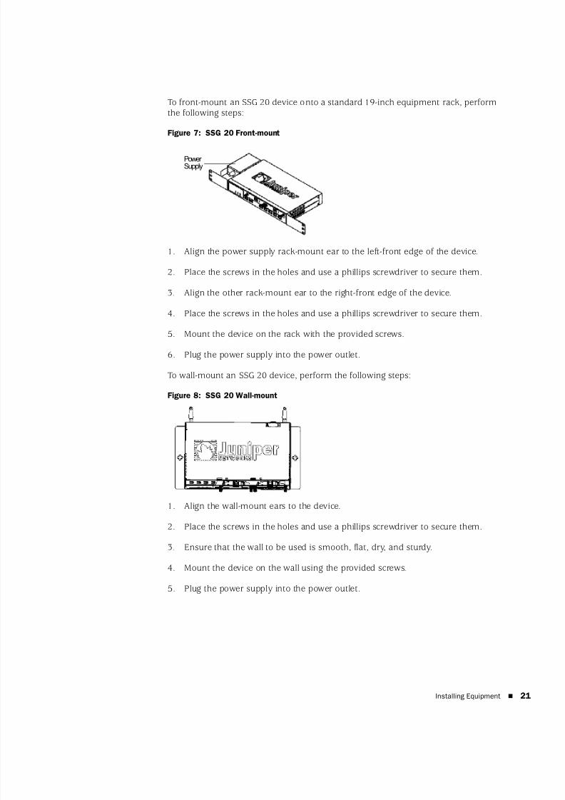
To front-mount an SSG 20 device onto a standard 19-inch equipment rack, performthe following steps:
Figure 7: SSG 20 Front-mount
1. Align the power supply rack-mount ear to the left-front edge of the device.
2. Place the screws in the holes and use a phillips screwdriver to secure them.
3. Align the other rack-mount ear to the right-front edge of the device.
4. Place the screws in the holes and use a phillips screwdriver to secure them.
5. Mount the device on the rack with the provided screws.
6. Plug the power supply into the power outlet.
To wall-mount an SSG 20 device, perform the following steps:
Figure 8: SSG 20 Wall-mount
1. Align the wall-mount ears to the device.
2. Place the screws in the holes and use a phillips screwdriver to secure them.
3. Ensure that the wall to be used is smooth, flat, dry, and sturdy.
4. Mount the device on the wall using the provided screws.
5. Plug the power supply into the power outlet.
Power Supply

8/3/2019 Cisco Ssg20
http://slidepdf.com/reader/full/cisco-ssg20 22/86
SSG 20 Hardware Installation and Configuration Guide
22 Connecting Interface Cables to a Device
To desk-mount an SSG 20 device, perform the following steps:
Figure 9: SSG 20 Desk-mount
1. Attach the desktop stand to the side of the device. We recommend using theside closest to the power adapter.
2. Place the mounted device on the desktop.3. Plug in the power adapter and connect the power supply to the power outlet.
Connecting Interface Cables to a Device
To connect the interface cable to a device, perform the following steps:
1. Have ready a length of the type of cable used by the interface.
2. Insert the cable connector into the cable-connector port on the interfacefaceplate.
3. Arrange the cable as follows to prevent it from dislodging or developing stresspoints:
a. Secure the cable so that it is not supporting its own weight as it hangs tothe floor.
b. Place any excess cable out of the way in a neatly coiled loop.
c. Use fasteners to maintain the shape of the cable loops.
Connecting the Power
To connect the power to a device, perform the following steps:1. Plug the DC-connector end of the power cable into the DC-power receptacle on
the back of the device.
2. Plug the AC-adapter end of the power cable into an AC-power source.
WARNING: We recommend using a surge protector for the power connection.
8/3/2019 Cisco Ssg20
http://slidepdf.com/reader/full/cisco-ssg20 23/86
Connecting a Device to a Network 23
Connecting a Device to a Network
An SSG 20 device provides firewall and general security for networks when it isplaced between internal networks and the untrusted network. This sectiondescribes the following:
Connecting a Device to an Untrusted Network
Connecting a Device to an Internal Network or a Workstation
Connecting a Device to an Untrusted Network
You can connect your SSG 20 device to an untrusted network in one of the followingways:
Ethernet Ports
Serial (AUX/Console) Ports
Connecting Mini PIMs to an Untrusted Network
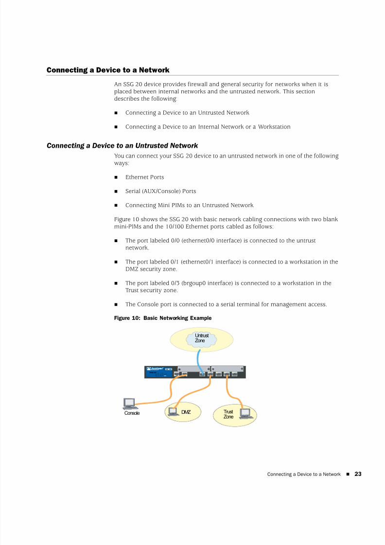
Figure 10 shows the SSG 20 with basic network cabling connections with two blankmini-PIMs and the 10/100 Ethernet ports cabled as follows:
The port labeled 0/0 (ethernet0/0 interface) is connected to the untrustnetwork.
The port labeled 0/1 (ethernet0/1 interface) is connected to a workstation in theDMZ security zone.
The port labeled 0/3 (brgoup0 interface) is connected to a workstation in theTrust security zone.
The Console port is connected to a serial terminal for management access.
Figure 10: Basic Networking Example
AUX 0/010 /100
AUX 0/010/100
0/010/100
0/010 /100
0/010 /100
LINK
STATUS
POWER
PIM 2
PIM 1
b/g
802.11a
WLAN
SSG 20
1 2
UntrustZone
TrustZone
DMZConsole
8/3/2019 Cisco Ssg20
http://slidepdf.com/reader/full/cisco-ssg20 24/86
SSG 20 Hardware Installation and Configuration Guide
24 Connecting a Device to a Network
Ethernet Ports
To establish a high-speed connection, connect the provided Ethernet cable from theEthernet port marked 0/0 on an SSG 20 device to the external router. The device
autosenses the correct speed, duplex, and MDI/MDIX settings.
Serial (AUX/Console) Ports
You can connect to the untrusted network with an RJ-45 straight-through serialcable and an external modem.
Connecting Mini PIMs to an Untrusted Network
This section explains how to connect the device mini PIMs to an untrusted network.
ADSL2/2+ Mini PIM
Connect the provided ADSL cable from the ADSL2/2+ mini PIM to your telephoneoutlet. The ADSL port on the Annex A version of the device uses an RJ-11 connector,while the Annex B version uses an RJ-45 connector. In the case of Annex B models,the cable you connect from the ADSL port to the telephone outlet is identical inappearance and wiring to a straight-through 10 Base-T Ethernet cable.
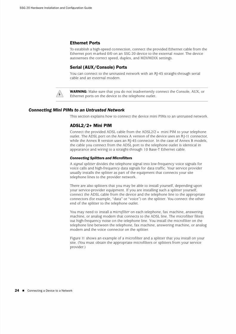
Connecting Splitters and Microfilters
A signal splitter divides the telephone signal into low-frequency voice signals forvoice calls and high-frequency data signals for data traffic. Your service providerusually installs the splitter as part of the equipment that connects your sitetelephone lines to the provider network.
There are also splitters that you may be able to install yourself, depending uponyour service-provider equipment. If you are installing such a splitter yourself,connect the ADSL cable from the device and the telephone line to the appropriateconnectors (for example, “data” or “voice”) on the splitter. You connect the otherend of the splitter to the telephone outlet.
You may need to install a microfilter on each telephone, fax machine, answeringmachine, or analog modem that connects to the ADSL line. The microfilter filtersout high-frequency noise on the telephone line. You install the microfilter on thetelephone line between the telephone, fax machine, answering machine, or analogmodem and the voice connector on the splitter.
Figure 11 shows an example of a microfilter and a splitter that you install on yoursite. (You must obtain the appropriate microfilters or splitters from your serviceprovider.)
WARNING: Make sure that you do not inadvertently connect the Console, AUX, orEthernet ports on the device to the telephone outlet.
8/3/2019 Cisco Ssg20
http://slidepdf.com/reader/full/cisco-ssg20 25/86
Connecting a Device to a Network 25
Figure 11: Microfilter and Splitter on Your Network Connection
ISDN, T1, E1, and V.92 Mini PIMs
To connect the mini PIMs to a device, perform the following steps:
1. Have ready a length of the type of cable used by the interface.
2. Insert the cable connector into the cable-connector port on the interfacefaceplate.
3. Arrange the cable as follows to prevent it from dislodging or developing stresspoints:
a. Secure the cable so that it is not supporting its own weight as it hangs tothe floor.
b. Place any excess cable out of the way in a neatly coiled loop.
c. Use fasteners to maintain the shape of the cable loops.
To configure the ISDN, E1, T1, or V.92 mini PIM, see “Mini PIM Configuration” onpage 41.
Connecting a Device to an Internal Network or a Workstation
You can connect your local area network (LAN) or workstation with the Ethernetand/or wireless interfaces.
Ethernet Ports
An SSG 20 device contains five Ethernet ports. You can use one or more of these
ports to connect to LANs through switches or hubs. You can also connect one or allof the ports directly to workstations, eliminating the need for a hub or switch. Youcan use either crossover or straight-through cables to connect the Ethernet ports toother devices. See “Default Device Settings” on page 31 for the defaultzone-to-interface bindings.
CONSOLEAUX
SSG 20TX/RX LINK
TX/RX
SYNC1 2
ADSL 2/2+
0/0 10/100 0/1 10/100 0/2 10/100 0/4 10/100 0/510/100
STATUS
POWER
PIM 2
PIM 1
b/g
802.11a
WLAN
TXRX
SYNC
ADSL 2+
D AT A V OICE
8/3/2019 Cisco Ssg20
http://slidepdf.com/reader/full/cisco-ssg20 26/86
SSG 20 Hardware Installation and Configuration Guide
26 Connecting a Device to a Network
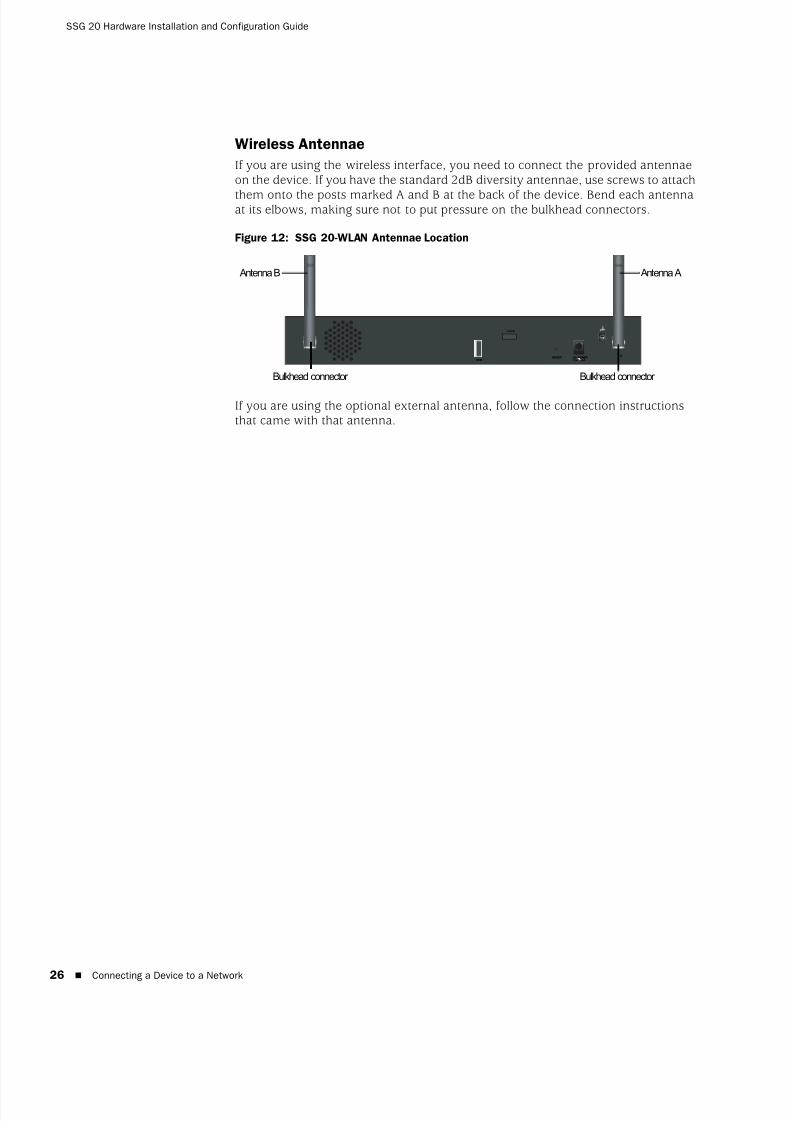
Wireless Antennae
If you are using the wireless interface, you need to connect the provided antennaeon the device. If you have the standard 2dB diversity antennae, use screws to attach
them onto the posts marked A and B at the back of the device. Bend each antennaat its elbows, making sure not to put pressure on the bulkhead connectors.
Figure 12: SSG 20-WLAN Antennae Location
If you are using the optional external antenna, follow the connection instructionsthat came with that antenna.
B A
LOCK
DC POWER12V A4
RESETUSB
Bulkhead connector Bulkhead connector
Antenna B Antenna A

8/3/2019 Cisco Ssg20
http://slidepdf.com/reader/full/cisco-ssg20 27/86
27
Chapter 3
Configuring the Device
ScreenOS software is preinstalled on an SSG 20 device. When the device is poweredon, it is ready to be configured. While the device has a default factory configurationthat allows you to initially connect to the device, you need to perform furtherconfiguration for your specific network requirements.
This chapter contains the following sections:
“Accessing a Device” on page 28
“Default Device Settings” on page 31
“Basic Device Configuration” on page 33
“Basic Wireless Configuration” on page 37
“Mini PIM Configuration” on page 41
“Basic Firewall Protections” on page 48
“Verifying External Connectivity” on page 48
“Resetting a Device to Factory Defaults” on page 49
NOTE: After you configure a device and verify connectivity through the remote network,you must register your product at www.juniper.net/support/ so certain ScreenOSservices, such as Deep Inspection Signature Service and Antivirus (purchasedseparately), can be activated on the device. After registering your product, use theWebUI to obtain the subscription for the service. For more information aboutregistering your product and obtaining subscriptions for specific services, refer tothe Fundamentals volume of the Concepts & Examples ScreenOS Reference Guide for
the ScreenOS version running on the device.
8/3/2019 Cisco Ssg20
http://slidepdf.com/reader/full/cisco-ssg20 28/86
SSG 20 Hardware Installation and Configuration Guide
28 Accessing a Device
Accessing a Device
You can configure and manage a device in several ways:
Console: The Console port on the device allows you to access the devicethrough a serial cable connected to your workstation or terminal. To configurethe device, you enter ScreenOS command line interface (CLI) commands onyour terminal or in a terminal-emulation program on your workstation.
WebUI: The ScreenOS Web User Interface (WebUI) is a graphical interfaceavailable through a browser. To initially use the WebUI, the workstation onwhich you run the browser must be on the same subnetwork as the device. Youcan also access the WebUI through a secure server using Secure Sockets Layer (SSL) with secure HTTP (S-HTTP).
Telnet/SSH: Telnet and SSH are applications that allows you to access devicesthrough an IP network. To configure the device, you enter ScreenOS CLI
commands in a Telnet session from your workstation. For more information,refer to the Administration volume of the Concepts & Examples ScreenOS Reference Guide.
NetScreen-Security Manager: NetScreen-Security Manager is a JuniperNetworks enterprise-level management application that enables you to controland manage Juniper Networks firewall/IPSec VPN devices. For instructions onhow to manage your device with NetScreen-Security Manager, refer to theNetScreen-Security Manager Administrator’s Guide.
Using a Console Connection
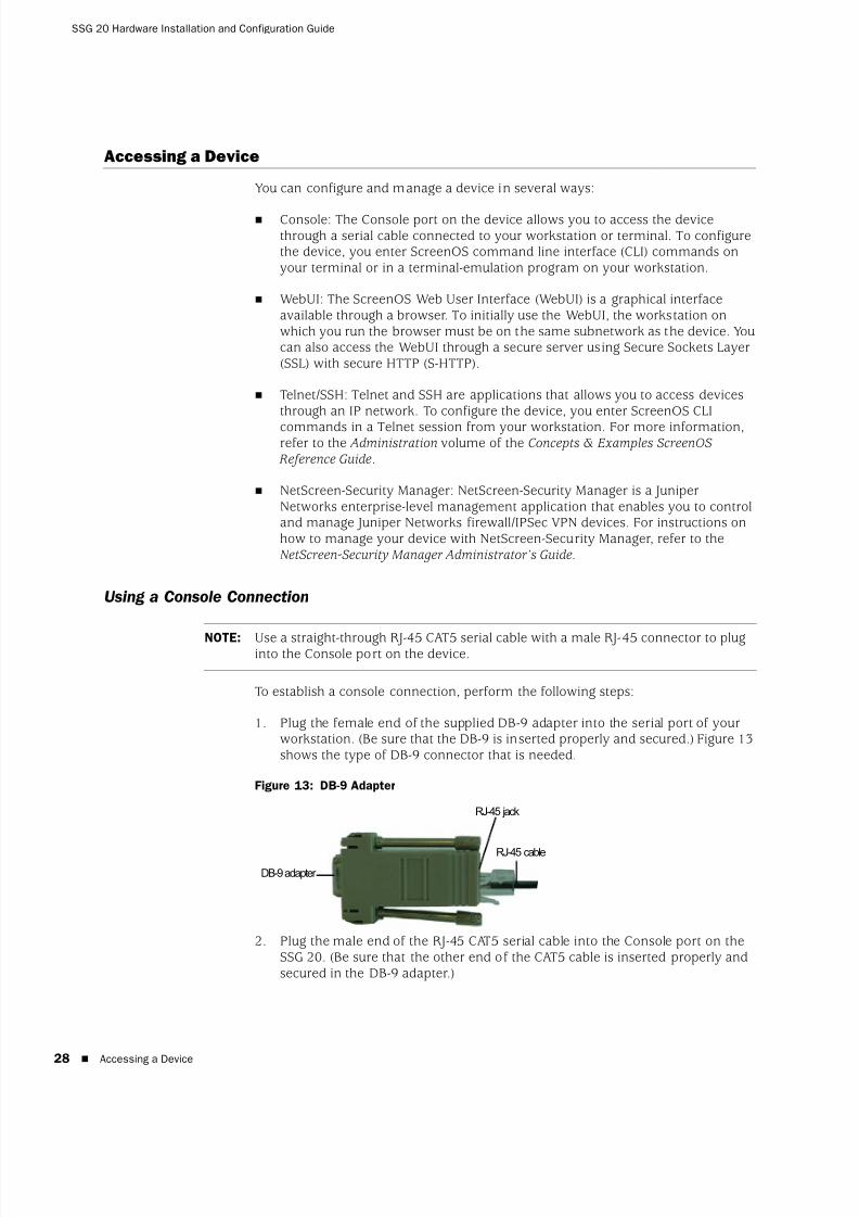
To establish a console connection, perform the following steps:
1. Plug the female end of the supplied DB-9 adapter into the serial port of yourworkstation. (Be sure that the DB-9 is inserted properly and secured.) Figure 13 shows the type of DB-9 connector that is needed.
Figure 13: DB-9 Adapter
2. Plug the male end of the RJ-45 CAT5 serial cable into the Console port on theSSG 20. (Be sure that the other end of the CAT5 cable is inserted properly andsecured in the DB-9 adapter.)
NOTE: Use a straight-through RJ-45 CAT5 serial cable with a male RJ-45 connector to pluginto the Console port on the device.
RJ-45 jack
DB-9 adapter
RJ-45 cable

8/3/2019 Cisco Ssg20
http://slidepdf.com/reader/full/cisco-ssg20 29/86
Accessing a Device 29
3. Launch a serial terminal-emulation program on your workstation. The requiredsettings to launch a console session are as follows:
Baud rate: 9600
Parity: None
Data bits: 8
Stop bit: 1
Flow Control: None
4. If you have not yet changed the default login for the admin name andpassword, enter netscreen at both the login and password prompts. (Uselowercase letters only. The login and password fields are both case-sensitive.)
For information on how to configure the device with the CLI commands, referto the Concepts & Examples ScreenOS Reference Guide.
5. (Optional) By default, the console times out and terminates automatically after10 minutes of idle time. To remove the timeout, enter set console timeout 0.
Using the WebUI
To use the WebUI, the workstation from which you are managing the device mustinitially be on the same subnetwork as the device. To access the device with theWebUI, perform the following steps:
1. Connect your workstation to the 0/2 — 0/4 port (bgroup0 interface in the Trustzone) on the device.
2. Ensure that your workstation is configured for Dynamic Host ConfigurationProtocol (DHCP) or is statically configured with an IP address in the192.168.1.0/24 subnet.
3. Launch your browser, enter the IP address for the bgroup0 interface (the defaultIP address is 192.168.1.1/24), then press Enter.
The WebUI application displays the login prompt as shown in Figure 14.
NOTE: When the device is accessed through the WebUI the first time, the InitialConfiguration Wizard (ICW) appears. If you decide to use the ICW to configureyour device, see “Initial Configuration Wizard” on page 63.

8/3/2019 Cisco Ssg20
http://slidepdf.com/reader/full/cisco-ssg20 30/86
SSG 20 Hardware Installation and Configuration Guide
30 Accessing a Device
Figure 14: WebUI Login Prompt
4. If you have not yet changed the default login for the admin name andpassword, enter netscreen at both the admin name and password prompts.(Use lowercase letters only. The login and password fields are bothcase-sensitive.)
Using Telnet
To establish a Telnet connection, perform the following steps:
1. Connect your workstation to the 0/2 — 0/4 port (bgroup0 interface in the Trustzone) on the device.
2. Ensure that your workstation is configured for DHCP or is statically configuredwith an IP address in the 192.168.1.0/24 subnet.
3. Start a Telnet client application to the IP address for the bgroup0 interface (thedefault IP address is 192.168.1.1). For example, enter telnet 192.168.1.1.
The Telnet application displays the login prompt.
4. If you have not yet changed the default login for the login and password, enternetscreen at both the login and password prompts. (Use lowercase letters only.The login and password fields are both case-sensitive.)
5. (Optional) By default, the console times out and terminates automatically after10 minutes of idle time. To remove the timeout, enter set console timeout 0.
8/3/2019 Cisco Ssg20
http://slidepdf.com/reader/full/cisco-ssg20 31/86
Default Device Settings 31
Default Device Settings
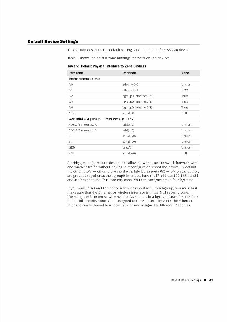
This section describes the default settings and operation of an SSG 20 device.
Table 5 shows the default zone bindings for ports on the devices.
Table 5: Default Physical Interface to Zone Bindings
A bridge group (bgroup) is designed to allow network users to switch between wiredand wireless traffic without having to reconfigure or reboot the device. By default,the ethernet0/2 — ethernet0/4 interfaces, labeled as ports 0/2 — 0/4 on the device,are grouped together as the bgroup0 interface, have the IP address 192.168.1.1/24,and are bound to the Trust security zone. You can configure up to four bgroups.
If you want to set an Ethernet or a wireless interface into a bgroup, you must firstmake sure that the Ethernet or wireless interface is in the Null security zone.Unsetting the Ethernet or wireless interface that is in a bgroup places the interfacein the Null security zone. Once assigned to the Null security zone, the Ethernetinterface can be bound to a security zone and assigned a different IP address.
Port Label Interface Zone
10/100 Ethernet ports:
0/0 ethernet0/0 Untrust
0/1 ethernet0/1 DMZ
0/2 bgroup0 (ethernet0/2) Trust
0/3 bgroup0 (ethernet0/3) Trust
0/4 bgroup0 (ethernet0/4) Trust
AUX serial0/0 Null
WAN mini PIM ports (x = mini PIM slot 1 or 2):
ADSL2/2+ (Annex A) adsl(x/0) Untrust
ADSL2/2+ (Annex B) adsl(x/0) Untrust
T1 serial(x/0) Untrust
E1 serial(x/0) Untrust
ISDN bri(x/0) Untrust
V.92 serial(x/0) Null
8/3/2019 Cisco Ssg20
http://slidepdf.com/reader/full/cisco-ssg20 32/86
SSG 20 Hardware Installation and Configuration Guide
32 Default Device Settings
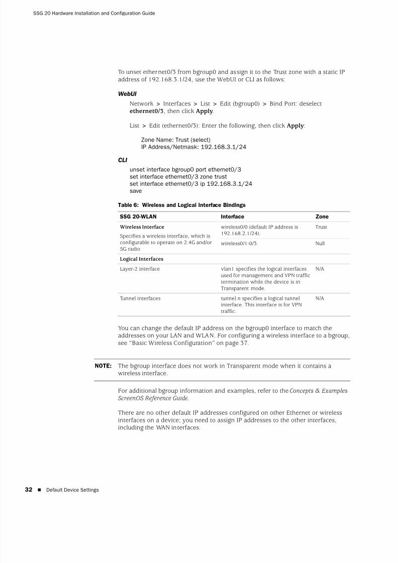
To unset ethernet0/3 from bgroup0 and assign it to the Trust zone with a static IPaddress of 192.168.3.1/24, use the WebUI or CLI as follows:
WebUI
Network > Interfaces > List > Edit (bgroup0) > Bind Port: deselectethernet0/3, then click Apply.
List > Edit (ethernet0/3): Enter the following, then click Apply:
Zone Name: Trust (select)IP Address/Netmask: 192.168.3.1/24
CLI
unset interface bgroup0 port ethernet0/3set interface ethernet0/3 zone trustset interface ethernet0/3 ip 192.168.3.1/24save
Table 6: Wireless and Logical Interface Bindings
You can change the default IP address on the bgroup0 interface to match theaddresses on your LAN and WLAN. For configuring a wireless interface to a bgroup,see “Basic Wireless Configuration” on page 37.
For additional bgroup information and examples, refer to the Concepts & ExamplesScreenOS Reference Guide.
There are no other default IP addresses configured on other Ethernet or wirelessinterfaces on a device; you need to assign IP addresses to the other interfaces,including the WAN interfaces.
SSG 20-WLAN Interface Zone
Wireless Interface
Specifies a wireless interface, which isconfigurable to operate on 2.4G and/or5G radio
wireless0/0 (default IP address is192.168.2.1/24).
Trust
wireless0/1-0/3. Null
Logical Interfaces
Layer-2 interface vlan1 specifies the logical interfacesused for management and VPN traffictermination while the device is inTransparent mode.
N/A
Tunnel interfaces tunnel.n specifies a logical tunnelinterface. This interface is for VPNtraffic.
N/A
NOTE: The bgroup interface does not work in Transparent mode when it contains awireless interface.

8/3/2019 Cisco Ssg20
http://slidepdf.com/reader/full/cisco-ssg20 33/86
Basic Device Configuration 33
Basic Device Configuration
This section describes the following basic configuration settings:
Root Admin Name and Password
Date and Time
Bridge Group Interfaces
Administrative Access
Management Services
Hostname and Domain Name
Default Route
Management Interface Address
Backup Untrust Interface Configuration
Root Admin Name and Password
The root admin user has complete privileges for configuring an SSG 20 device. Werecommend that you change the default root admin name and password (bothnetscreen) immediately.
To change the root admin name and password, use the WebUI or CLI as follows:
WebUI
Configuration > Admin > Administrators > Edit (for the netscreenadministrator name value): Enter the following, then click OK:
Administrator Name:Old Password: netscreenNew Password:Confirm New Password:
CLI
set admin name name
set admin password pswd_str save
NOTE: Passwords are not displayed in the WebUI.
8/3/2019 Cisco Ssg20
http://slidepdf.com/reader/full/cisco-ssg20 34/86
SSG 20 Hardware Installation and Configuration Guide
34 Basic Device Configuration
Date and Time
The time set on an SSG 20 device affects events such as the setup of VPN tunnels.The easiest way to set the date and time on the device is to use the WebUI to
synchronize the device system clock with the workstation clock.
To configure the date and time on a device, use the WebUI or CLI as follows:
WebUI
1. Configuration > Date/Time: Click the Sync Clock with Client button.
A pop-up message prompts you to specify if you have enabled the daylightsaving time option on your workstation clock.
2. Click Yes to synchronize the system clock and adjust it according todaylight saving time, or click No to synchronize the system clock withoutadjusting for daylight saving time.
You can also use the set clock CLI command in a Telnet or Console session tomanually enter the date and time for the device.
Bridge Group Interfaces
By default, the SSG 20 device has Ethernet interfaces ethernet0/2 — ethernet0/4grouped together in the Trust security zone. Grouping interfaces sets interfaces inone subnet. You can unset an interface from a group and assign it to a differentsecurity zone. Interfaces must be in the Null security zone before they can beassigned to a group. To place a grouped interface in the Null security zone, use theunset interface interface port interface CLI command.
The SSG 20-WLAN devices allow Ethernet and wireless interfaces to be groupedunder one subnet.
To configure a group with Ethernet and wireless interfaces, use the WebUI or CLI asfollows:
WebUI
Network > Interfaces > List > Edit (bgroup0) > Bind Port: deselectethernet0/3 and ethernet0/4, then click Apply.
Edit (bgroup1) > Bind Port: select ethernet0/3, ethernet0/4, and wireless0/2,then click Apply.
>Basic: Enter the following, then click Apply:
Zone Name: DMZ (select)IP Address/Netmask: 10.0.0.1/24
NOTE: Only wireless and Ethernet interfaces can be set in a bgroup.
8/3/2019 Cisco Ssg20
http://slidepdf.com/reader/full/cisco-ssg20 35/86
Basic Device Configuration 35
CLI
unset interface bgroup0 port ethernet0/3unset interface bgroup0 port ethernet0/4
set interface bgroup1 port ethernet0/3set interface bgroup1 port ethernet0/4set interface bgroup1 port wireless0/2set interface bgroup1 zone DMZset interface bgroup1 ip 10.0.0.1/24save
Administrative Access
By default, anyone in your network can manage a device if they know the login andpassword.
To configure the device to be managed only from a specific host on your network,use the WebUI or CLI as follows:
WebUI
Configuration > Admin > Permitted IPs: Enter the following, then click Add:
IP Address/Netmask: ip_addr/mask
CLI
set admin manager-ip ip_addr/mask
save
Management Services
ScreenOS provides services for configuring and managing the device, such as
SNMP, SSL, and SSH, which you can enable on a per-interface basis.
To configure the management services on the device, use the WebUI or CLI asfollows:
WebUI
Network > Interfaces > List > Edit (for ethernet0/0): Under Management Services, select or clear the management services you want to use on theinterface, then click Apply.
CLI
set interface ethernet0/0 manage webunset interface ethernet0/0 manage snmp
save
8/3/2019 Cisco Ssg20
http://slidepdf.com/reader/full/cisco-ssg20 36/86
SSG 20 Hardware Installation and Configuration Guide
36 Basic Device Configuration
Hostname and Domain Name
The domain name defines the network or subnetwork that the device belongs to,while the hostname refers to a specific device. The hostname and domain name
together uniquely identify the device in the network.
To configure the hostname and domain name on a device, use the WebUI or CLI asfollows:
WebUI
Network > DNS > Host: Enter the following, then click Apply:
Host Name: name
Domain Name: name
CLI
set hostname name
set domain namesave
Default Route
The default route is a static route used to direct packets addressed to networks thatare not explicitly listed in the routing table. If a packet arrives at the device with anaddress for which the device does not have routing information, the device sendsthe packet to the destination specified by the default route.
To configure the default route on the device, use the WebUI or CLI as follows:
WebUI
Network > Routing > Destination > New (trust-vr): Enter the following, thenclick OK:
IP Address/Netmask: 0.0.0.0/0.0.0.0Next Hop
Gateway: (select)Interface: ethernet0/2 (select)Gateway IP Address: ip_addr
CLI
set route 0.0.0.0/0 interface ethernet0/2 gateway ip_addr
save
Management Interface Address
The Trust interface has the default IP address 192.168.1.1/24 and is configured formanagement services. If you connect the 0/2 — 0/4 ports on the device to aworkstation, you can configure the device from a workstation in the 192.168.1.1/24subnetwork using a management service such as Telnet.
You can change the default IP address on the Trust interface. For example, youmight want to change the interface to match IP addresses that already exist on yourLAN.
8/3/2019 Cisco Ssg20
http://slidepdf.com/reader/full/cisco-ssg20 37/86
Basic Wireless Configuration 37
Backup Untrust Interface Configuration
The SSG 20 device allows you to configure a backup interface for untrust failover. Toset a backup interface for untrust failover, perform the following steps:
1. Set the backup interface in the Null security zone with the unset interfaceinterface [port interface] CLI command.
2. Bind the backup interface to the same security zone as the primary interfacewith the set interface interface zone zone_name CLI command.
To set the ethernet0/4 interface as the backup interface to the ethernet0/0 interface,
use the WebUI or CLI as follows:
WebUI
Network > Interfaces > Backup > Enter the following, then click Apply.
Primary: ethernet0/0Backup: ethernet0/4Type: track-ip (select)
CLI
unset interface bgroup0 port ethernet0/4set interface ethernet0/4 zone untrustset interface ethernet0/0 backup interface ethernet0/4 type track-ip
save
Basic Wireless Configuration
This section provides information for configuring the wireless interface on theSSG 20-WLAN device. Wireless networks consist of names referred to as Service SetIdentifiers (SSIDs). Specifying SSIDs allows you to have multiple wireless networksreside in the same location without interfering with each other. An SSID name canhave a maximum of 32 characters. If a space is part of the SSID name string, thenthe string must be enclosed with quotation marks. Once the SSID name is set, moreSSID attributes can be configured.To use the wireless local area network (WLAN)capabilities on the device, you must configure at least one SSID and bind it to awireless interface.
The SSG 20-WLAN device allows you to create up to 16 SSIDs, but only 4 of themcan be used simultaneously. You can configure the device to use the 4 SSIDs oneither one of the transceivers or split the use on both (for example, 3 SSIDs assignedto WLAN 0 and 1 SSID assigned to WLAN 1.) Use the set interface wireless_interface wlan {0 | 1 | both} CLI command to set the radio transceivers onthe SSG 20-WLAN device.
NOTE: The primary and backup interfaces must be in the same security zone. Oneprimary interface has only one backup interface, and one backup interface hasonly one primary interface.
8/3/2019 Cisco Ssg20
http://slidepdf.com/reader/full/cisco-ssg20 38/86
SSG 20 Hardware Installation and Configuration Guide
38 Basic Wireless Configuration
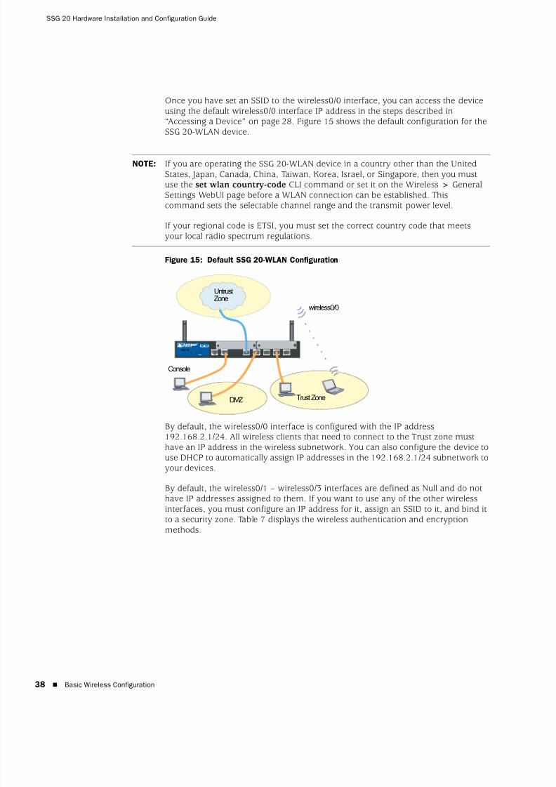
Once you have set an SSID to the wireless0/0 interface, you can access the deviceusing the default wireless0/0 interface IP address in the steps described in“Accessing a Device” on page 28. Figure 15 shows the default configuration for theSSG 20-WLAN device.
Figure 15: Default SSG 20-WLAN Configuration
By default, the wireless0/0 interface is configured with the IP address192.168.2.1/24. All wireless clients that need to connect to the Trust zone musthave an IP address in the wireless subnetwork. You can also configure the device touse DHCP to automatically assign IP addresses in the 192.168.2.1/24 subnetwork toyour devices.
By default, the wireless0/1 – wireless0/3 interfaces are defined as Null and do nothave IP addresses assigned to them. If you want to use any of the other wirelessinterfaces, you must configure an IP address for it, assign an SSID to it, and bind itto a security zone. Table 7 displays the wireless authentication and encryptionmethods.
NOTE: If you are operating the SSG 20-WLAN device in a country other than the UnitedStates, Japan, Canada, China, Taiwan, Korea, Israel, or Singapore, then you mustuse the set wlan country-code CLI command or set it on the Wireless > GeneralSettings WebUI page before a WLAN connection can be established. Thiscommand sets the selectable channel range and the transmit power level.
If your regional code is ETSI, you must set the correct country code that meetsyour local radio spectrum regulations.
AUX 0/0
10 /100
AUX0/0 10/100 0/0 10/100 0/0 10 /100 0/0 10 /100
LINK
STATUS
POWER
PIM 2
PIM 1
b/g
802.11a
WLAN
SSG 20
1 2
UntrustZone
Trust Zone
wireless0/0
Console
DMZ
8/3/2019 Cisco Ssg20
http://slidepdf.com/reader/full/cisco-ssg20 39/86
Basic Wireless Configuration 39
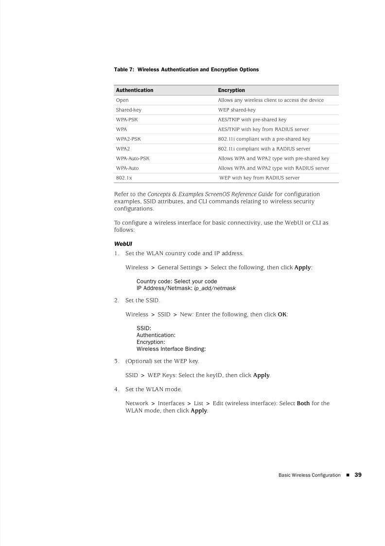
Table 7: Wireless Authentication and Encryption Options
Refer to the Concepts & Examples ScreenOS Reference Guide for configurationexamples, SSID attributes, and CLI commands relating to wireless securityconfigurations.
To configure a wireless interface for basic connectivity, use the WebUI or CLI asfollows:
WebUI
1. Set the WLAN country code and IP address.
Wireless > General Settings > Select the following, then click Apply:
Country code: Select your code
IP Address/Netmask: ip_add/netmask
2. Set the SSID.
Wireless > SSID > New: Enter the following, then click OK:
SSID:Authentication:Encryption:Wireless Interface Binding:
3. (Optional) set the WEP key.
SSID > WEP Keys: Select the keyID, then click Apply.
4. Set the WLAN mode.
Network > Interfaces > List > Edit (wireless interface): Select Both for theWLAN mode, then click Apply.
Authentication Encryption
Open Allows any wireless client to access the device
Shared-key WEP shared-key
WPA-PSK AES/TKIP with pre-shared key
WPA AES/TKIP with key from RADIUS server
WPA2-PSK 802.11i compliant with a pre-shared key
WPA2 802.11i compliant with a RADIUS server
WPA-Auto-PSK Allows WPA and WPA2 type with pre-shared key
WPA-Auto Allows WPA and WPA2 type with RADIUS server
802.1x WEP with key from RADIUS server
8/3/2019 Cisco Ssg20
http://slidepdf.com/reader/full/cisco-ssg20 40/86
SSG 20 Hardware Installation and Configuration Guide
40 Basic Wireless Configuration
5. Activate wireless changes.
Wireless > General Settings > Click Activate Changes.
CLI
1. Set the WLAN country code and IP address.
set wlan country-code {code_id}set interface wireless_interface ip ip_addr/netmask
2. Set the SSID.
set ssid name name_str
set ssid name_str authentication auth_type encryption encryption_type
set ssid name_str interface interface
(optional) set ssid name_str key-id number
3. Set the WLAN mode.
set interface wireless_interface wlan both
4. Activate wireless changes.
saveexec wlan reactivate
You can set an SSID to operate in the same subnet as the wired subnet. This actionallows clients to work in either interface without having to reconnect in anothersubnet.
To set an Ethernet and a wireless interface to the same bridge-group interface, usethe WebUI or CLI as follows:
WebUI
Network > Interfaces > List > Edit (bgroup_name) > Bind Port: Select thewireless and ethernet interfaces, then click Apply.
CLI
set interface bgroup_name port wireless_interfaceset interface bgroup_name port ethernet_interface
NOTE: Bgroup_name can be bgroup0—bgroup3.
Ethernet_interface can be ethernet0/0—ethernet0/4.
Wireless_interface can be wireless0/0—wireless0/3.
If a wireless interface is configured, then you need to reactivate the WLAN withthe exec wlan reactivate CLI command or click Activate Changes on the Wireless> General Settings WebUI page.

8/3/2019 Cisco Ssg20
http://slidepdf.com/reader/full/cisco-ssg20 41/86
Mini PIM Configuration 41
Mini PIM Configuration
This section explains how to configure the mini physical interface modules (PIMs):
ADSL2/2+ Interface
ISDN Interface
T1 Interface
E1 Interface
V.92 Modem Interface
ADSL2/2+ Interface
Your network uses the ADSL2/2+ interface adslx/0, with x representing the mini
PIM slot (1 or 2), on the device to connect to the service provider’s network throughan Asynchronous Transfer Mode (ATM) virtual circuit. You can configure additionalvirtual circuits by creating ADSL2/2+ subinterfaces. For more information, see“Virtual Circuits” on page 42.
In the WebUI, navigate to the Network > Interfaces > List page to see a list of thecurrent interfaces on the device. If you are using a Telnet or Console session, enterthe get interface CLI command. You should see that the adslx/0 interface is boundto the Untrust zone.
If you are using the ADSL2/2+ interface to connect to the service network of theprovider, you must configure the adsl(x/0) interface. To do this, you must obtain thefollowing information from your service provider:
Virtual Path Identifier and Virtual Channel Identifier (VPI/VCI) values
ATM Adaptation Layer 5 (AAL5) multiplexing method, which can be one of thefollowing:
Virtual circuit-based multiplexing, in which each protocol is carried over aseparate ATM virtual circuit
Logical Link Control (LLC) encapsulation, which allows several protocols tobe carried on the same ATM virtual circuit (the default multiplexingmethod)
Username and password assigned by the service provider for connection to the
service provider’s network using either Point-to-Point Protocol over Ethernet(PPPoE) or Point-to-Point Protocol over ATM (PPPoA)
Authentication method, if any, provided for the PPPoE or PPPoA connection
Optionally, a static IP address and netmask value for your network

8/3/2019 Cisco Ssg20
http://slidepdf.com/reader/full/cisco-ssg20 42/86
SSG 20 Hardware Installation and Configuration Guide
42 Mini PIM Configuration
Virtual Circuits
To add virtual circuits, you create subinterfaces to the ADSL2/2+ interface. You cancreate up to 10 ADSL2/2+ subinterfaces. For example, to create a new subinterface
named adsl1/0.1 bound to the predefined zone named Untrust , use the WebUI orCLI as follows:
WebUI
Network > Interfaces > List > New ADSL Sub-IF: Enter the following, thenclick Apply:
Interface Name: adsl1/0.1VPI/VCI: 0/35Zone Name: Untrust (select)
CLI
set interface adsl 1/0.1 pvc 0 35 zone Untrust
save
You need to configure an ADSL 2/2+subinterface in the same way as the mainADSL2/2+ interface, including setting the VPI/VCI values, as described in“ADSL2/2+ Interface” on page 41. You configure an ADSL2/2+ subinterfaceindependently of the main ADSL2/2+ interface; that is, you can configure adifferent multiplexing method, VPI/VCI, and PPP client on the subinterface than onthe main ADSL2/2+ interface. You can also configure a static IP address on asubinterface, even if the main ADSL2/2+ interface does not have a static IPaddress.
VPI/VCI and Multiplexing Method
Your service provider assigns a VPI/VCI pair for each virtual-circuit connection. For
example, you may receive the VPI/VCI pair 1/32, which means a VPI value of 1 anda VCI value of 32. These values must match the values that the service provider hasconfigured on the subscriber’s side of the Digital Subscriber Line Access Multiplexer(DSLAM).
To configure the VPI/VCI pair 1/32 on the adsl1/0 interface, use the WebUI or CLI asfollows:
WebUI
Network > Interfaces > List > Edit (for the adsl1/0 interface): Enter 1/32 inthe VPI/VCI field, then click Apply.
CLI
set interface adsl1/0 pvc 1 32save
By default, the device uses Logical Link Control (LLC)-based multiplexing for eachvirtual circuit.
To configure the VPI/VCI 1/32 on the adslx/0 interface and use LLC encapsulation onthe virtual circuit, use the WebUI or CLI as follows:

8/3/2019 Cisco Ssg20
http://slidepdf.com/reader/full/cisco-ssg20 43/86
Mini PIM Configuration 43
WebUI
Network > Interfaces > List > Edit (for the adsl1/0 interface): Enter thefollowing, then click Apply:
VPI/VCI: 1 / 32Multiplexing Method: LLC (selected)
CLI
set interface adsl1/0 pvc 1 32 mux llcsave
PPPoE or PPPoA
An SSG 20 device includes both PPPoE and PPPoA clients to connect to the serviceprovider’s network over the ADSL link. PPPoE is the most common form of ADSLencapsulation and is intended for termination on each host on your network.PPPoA is used primarily for business-class service, as PPP sessions can be
terminated on the device. To allow the device to connect to the network of theservice provider, you need to configure the username and password assigned by theservice provider. The configuration for PPPoA is similar to the configuration forPPPoE.
To configure the username roswell and password area51 for PPPoE and bind thePPPoE configuration to the adsl1/0 interface, use the WebUI or CLI as follows:
WebUI
Network > PPP > PPPoE Profile> New: Enter the following, then click OK:
PPPoE Instance: poe1Bound to Interface: adsl1/0 (select)Username: roswellPassword: area51
CLI
set pppoe name poe1 username roswell password area51set pppoe name poe1 interface adsl1/0save
There are other PPPoE or PPPoA parameters that you can configure on the device,including method of authentication (by default, the device supports eitherChallenge Handshake Authentication Protocol or Password Authentication Protocol),idle timeout (default is 30 minutes), and so on. Ask your service provider if thereare additional PPPoE or PPPoA parameters that you need to configure to enableproper communications with the service provider’s server.
NOTE: The device supports only one PPPoE session on each virtual circuit.

8/3/2019 Cisco Ssg20
http://slidepdf.com/reader/full/cisco-ssg20 44/86
SSG 20 Hardware Installation and Configuration Guide
44 Mini PIM Configuration
Static IP Address and Netmask
If your service gave you a specific, fixed IP address and netmask for your network,then configure the IP address and netmask for the network and the IP address of
the router port connected to the device. You need to also specify that the device isto use the static IP address. (Typically, the device acts as a PPPoE or PPPoA clientand receives an IP address for the ADSL interface through negotiations with thePPPoE or PPPoA server.)
You need to configure a PPPoE or PPPoA instance and bind it to the adsl1/0interface, as described in “PPPoE or PPPoA” on page 43. Make sure that you selectObtain IP using PPPoE or Obtain IP using PPPoA and the name of the PPPoE orPPPoA instance.
To configure the static IP address 1.1.1.1/24 for the network, use the WebUI or CLIas follows:
WebUI
Network > Interfaces > List > Edit (for the adsl1/0 interface): Enter thefollowing, then click Apply:
IP Address/Netmask: 1.1.1.1/24Static IP: (select)
CLI
set interface adsl1/0 ip 1.1.1.1/24set pppoe name poe1 static-ipsave
or
set interface adsl1/0 ip 1.1.1.1/24set pppoa name poa1 static-ipsave
To use Domain Name System (DNS) for domain name and address resolution, thecomputers in your network need to have the IP address of at least one DNS server.If the device receives an IP address for the ADSL2/2+ interface through PPPoE orPPPoA, then it also automatically receives IP addresses for the DNS server(s). If thecomputers in your network obtain their IP address(es) from the DHCP server on thedevice, then the computers also obtain these DNS server addresses.
If you assign a static IP address to the ADSL2/2+ interface, then the serviceprovider must give you the IP address(es) of the DNS server(s). You can eitherconfigure the DNS server address on each computer in your network or you can
configure the DHCP server on the Trust zone interface so that it provides the DNSserver address to each computer.
To configure the DHCP server on the bgroup0 interface to provide the DNS serveraddress 1.1.1.152 to computers in your network, use the WebUI or CLI as follows:
WebUI
Network > DHCP > Edit (for the bgroup0 interface) > DHCP Server: Enter1.1.1.152 for DNS1, then click Apply.
8/3/2019 Cisco Ssg20
http://slidepdf.com/reader/full/cisco-ssg20 45/86
Mini PIM Configuration 45
CLI
set interface bgroup0 dhcp server option dns1 1.1.1.152save
For more information about configuring the ADSL and ADSL2/2+ interfaces, referto the Concepts & Examples ScreenOS Reference Guide.
ISDN Interface
Integrated Services Digital Network (ISDN) is a set of standards for digitaltransmission over different media created by the Consultative Committee forInternational Telegraphy and Telephone (CCITT) and InternationalTelecommunications Union (ITU). As a dial-on-demand service, it has fast call setupand low latency as well as the ability to carry high-quality voice, data, and videotransmissions. ISDN is also a circuit-switched service that can be used on bothmultipoint and point-to-point connections. ISDN provides a service router with amultilink Point-to-Point Protocol (PPP) connection for network interfaces. The ISDN
interface is usually configured as the backup interface of the Ethernet interface toaccess external networks.
To configure the ISDN interface, use the WebUI or CLI as follows:
WebUI
Network > Interfaces > List > Edit (bri1/0): Enter or select the following, thenclick OK:
BRI Mode: Dial Using BRIPrimary Number: 123456WAN Encapsulation: PPPPPP Profile: isdnprofile
CLI
set interface bri1/0 dialer-enableset interface bri1/0 primary-number "123456"set interface bri1/0 encap pppset interface bri1/0 ppp profile isdnprofilesave
To configure the ISDN interface as the backup interface, see “Backup UntrustInterface Configuration” on page 37.
For more information on how to configure the ISDN interface, refer to the Concepts& Examples ScreenOS Reference Guide.
T1 Interface
The T1 interface is a basic Physical Layer protocol used by the Digital Signal level 1(DS-1) multiplexing method in North America. A T1 interface operates at a bit-rateof 1.544 Mbps or speeds up to 24 DS0 channels.
The devices support the following T1 DS-1 standards:
ANSI TI.107, TI.102
GR 499-core, GR 253-core
8/3/2019 Cisco Ssg20
http://slidepdf.com/reader/full/cisco-ssg20 46/86
SSG 20 Hardware Installation and Configuration Guide
46 Mini PIM Configuration
AT&T Pub 54014
ITU G.751, G.703
To configure the T1 mini PIM, use the WebUI or CLI as follows:
WebUI
Network > Interfaces > List > Edit (serial1/0): Enter or select the following,then click OK:
WAN Configure: main linkWAN Encapsulation: cisco-hdlcClick Apply
Fixed IP: (select)IP Address/Netmask 172.18.1.1/24
CLI
set interface serial1/0 encap cisco-hdlcset interface serial1/0 ip 172.18.1.1/24
For information on how to configure the T1 interface, refer to the Concepts & Examples ScreenOS Reference Guide.
E1 Interface
The E1 interface is a standard wide area network (WAN) digital communicationsformat designed to operate over copper facilities at a rate of 2.048 Mbps. Widelyused outside North America, E1 is a basic time-division multiplexing scheme usedto carry digital circuits.
The devices support the following E1 standards:
ITU-T G.703
ITU-T G.751
ITU-T G.775
To configure the E1 mini PIM, use the WebUI or CLI as follows:
WebUI
Network > Interfaces > List > Edit (serial1/0): Enter or select the following,then click OK:
WAN Configure: main linkWAN Encapsulation: PPPBinding a PPP Profile: junipertestClick Apply
Fixed IP: (select)IP Address/Netmask 172.18.1.1/24
CLI
set interface serial1/0 encapsulation pppset ppp profile “junipertest” static-ipset ppp profile “junipertest” auth type chap
8/3/2019 Cisco Ssg20
http://slidepdf.com/reader/full/cisco-ssg20 47/86
Mini PIM Configuration 47
set ppp profile “junipertest” auth local-name “juniper”set ppp profile “junipertest” auth secret “password”set interface serial1/0 ppp profile “junipertest”set interface serial1/0 ip 172.18.1.1/24
set user “server” type wanset user “server” password “server”
For information on how to configure the E1 interface, refer to the Concepts & Examples ScreenOS Reference Guide.
V.92 Modem Interface
The V.92 interface provides an internal analog modem to establish a PPPconnection to a service provider. You can configure the serial interface as a primaryor backup interface, which is used in case of interface failover.
To configure the V.92 interface, use the WebUI or CLI as follows:
WebUI
Network > Interfaces > List > Edit (for serial1/0): Enter the following, thenclick OK:
Zone Name: untrust (select)
ISP: Enter the following, then click OK:
ISP Name: isp_juniperPrimary Number: 1234567
Login Name: juniperLogin Password: juniper
Modem: Enter the following, then click OK:
Modem Name: mod1Init String: AT&FS7=255S32=6Active Modem setting
Inactivity Timeout: 20
CLI
set interface serial1/0 zone untrustset interface serial1/0 modem isp isp_juniper account login juniper password
juniper
set interface serial1/0 modem isp isp_juniper primary-number 1234567set interface serial1/0 modem idle-time 20set interface serial1/0 modem settings mod1 init-strings AT&FS7=255S32=6set interface serial1/0 modem settings mod1 active
For information on how to configure the V.92 modem interface, refer to theConcepts & Examples ScreenOS Reference Guide.
NOTE: The V.92 interface does not work in Transparent mode.
8/3/2019 Cisco Ssg20
http://slidepdf.com/reader/full/cisco-ssg20 48/86
SSG 20 Hardware Installation and Configuration Guide
48 Basic Firewall Protections
Basic Firewall Protections
The devices are configured with a default policy that permits workstations in theTrust zone of your network to access any resource in the Untrust security zone,while outside computers are not allowed to access or start sessions with yourworkstations. You can configure policies that direct the device to permit outsidecomputers to start specific kinds of sessions with your computers. For informationabout creating or modifying policies, refer to the Concepts & Examples ScreenOS Reference Guide.
The SSG 20 device provides various detection methods and defense mechanisms tocombat probes and attacks aimed at compromising or harming a network ornetwork resource:
ScreenOS SCREEN options secure a zone by inspecting, and then allowing ordenying, all connection attempts that require crossing an interface to that zone.For example, you can apply port-scan protection on the Untrust zone to stop a
source from a remote network from trying to identify services to target forfurther attacks.
The device applies firewall policies, which can contain content-filtering andIntrusion Detection and Prevention (IDP) components, to the traffic that passesthe SCREEN filters from one zone to another. By default, no traffic is permittedto pass through the device from one zone to another. To permit traffic to crossthe device from one zone to another, you must create a policy that overrides thedefault behavior.
To set ScreenOS SCREEN options for a zone, use the WebUI or CLI as follows:
WebUI
Screening > Screen: Select the zone to which the options apply. Select theSCREEN options that you want, then click Apply:
CLI
set zone zone screen option
save
For more information about configuring the network-security options available inScreenOS, refer to the Concepts & Examples ScreenOS Reference Guide.
Verifying External Connectivity
To verify that workstations in your network can access resources on the Internet,start a browser from any workstation in the network and enter the following URL:www.juniper.net.
8/3/2019 Cisco Ssg20
http://slidepdf.com/reader/full/cisco-ssg20 49/86
Resetting a Device to Factory Defaults 49
Resetting a Device to Factory Defaults
If you lose the admin password, you can reset the device to its default settings. Thisaction destroys any existing configurations but restores access to the device.
You can restore the device to its default settings in one of the following ways:
Using a Console connection. For further information, refer to the Concepts & Examples ScreenOS Reference Guide.
Using the reset pinhole on the back panel of the device, as described in the nextsection.
You can reset the device and restore the factory default settings by pressing thereset pinhole. To perform this operation, you need to either view the device statusLEDs on the front panel or start a Console session as described in “Using a ConsoleConnection” on page 28.
To use the reset pinhole to reset and restore the default settings, perform thefollowing steps:
1. Locate the reset pinhole on the rear panel. Using a thin, firm wire (such as apaperclip), push the pinhole for four to six seconds and then release.
The STATUS LED blinks red. A message on the console states that erasure of theconfiguration has started and the system sends an SNMP/SYSLOG alert.
2. Wait for one to two seconds.
After the first reset, the STATUS LED blinks green; the device is now waiting forthe second reset. The Console message now states that the device is waiting fora second confirmation.
3. Push the reset pinhole again for four to six seconds.
The Console message verifies the second reset. The STATUS LED glows red forone-half second and then returns to the blinking green state.
The device then resets to its original factory settings. When the device resets,the STATUS LED glows red for one-half second and then glows green. Theconsole displays device-bootup messages. The system generates SNMP andSYSLOG alerts to configured SYSLOG or SNMP trap hosts.
After the device has rebooted, the console displays the login prompt for thedevice. The STATUS LED blinks green. The login and password are netscreen.
If you do not follow the complete sequence, the reset process cancels without anyconfiguration change and the Console message states that the erasure of theconfiguration is aborted. The STATUS LED returns to blinking green. If the devicedid not reset, an SNMP alert is sent to confirm the failure.
WARNING: Resetting the device deletes all existing configuration settings anddisables all existing firewall and VPN services.

8/3/2019 Cisco Ssg20
http://slidepdf.com/reader/full/cisco-ssg20 50/86
SSG 20 Hardware Installation and Configuration Guide
50 Resetting a Device to Factory Defaults

8/3/2019 Cisco Ssg20
http://slidepdf.com/reader/full/cisco-ssg20 51/86
Required Tools and Parts 51
Chapter 4
Servicing the Device
This chapter describes service and maintenance procedures for an SSG 20 device. Itcontains the following sections:
“Required Tools and Parts” on this page
“Replacing a Mini-Physical Interface Module” on this page
“Upgrading Memory” on page 54
Required Tools and Parts
To replace a component on an SSG 20 device, you need the following tools andparts:
Electrostatic bag or antistatic mat
Electrostatic discharge (ESD) grounding wrist strap
Phillips screwdriver, 1/8-inch
Replacing a Mini-Physical Interface Module
Both SSG 20 models have two slots in the front panel for wide area network miniphysical interface modules (WAN mini PIMs). Mini PIMs in an SSG 20 device can beinstalled and replaced. The device must be powered off before you can remove orinstall a mini PIM.
NOTE: For safety warnings and instructions, refer to the Juniper Networks Security Products Safety Guide. The instructions in the guide warn you about situations thatcould cause bodily injury. Before working on any equipment, you should be awareof the hazards involved with electrical circuitry and be familiar with standardpractices for preventing accidents.
CAUTION: Make sure the power is off to the device when removing a mini PIM.They are not hot-swappable.

8/3/2019 Cisco Ssg20
http://slidepdf.com/reader/full/cisco-ssg20 52/86
SSG 20 Hardware Installation and Configuration Guide
52 Replacing a Mini-Physical Interface Module
Removing a Blank Faceplate
To maintain proper airflow through the SSG 20 device, blank faceplates shouldremain over slots that do not contain mini PIMs. Do not remove a blank faceplate
unless you are installing a mini PIM in its empty slot.
To remove a blank faceplate, perform the following steps:
1. Place an electrostatic bag or antistatic mat on a flat, stable surface on whichyou intend to place the mini PIM.
2. Attach an ESD grounding strap to your bare wrist and connect the strap to theESD point on the chassis or to an outside ESD point if the SSG 20 device isdisconnected from earth ground.
3. Unplug the power adapter from the device. Verify that the POWER LED is off.
4. Loosen and remove the screws on each side of the faceplate using ascrewdriver.
5. Remove the faceplate, then place the faceplate in the electrostatic bag or on theantistatic mat.
Removing a Mini PIM
Mini PIMs are installed in the front panel of the SSG 20 device. A mini PIM weighsless than 0.2 lb (106g).
To remove a mini PIM, perform the following steps:
1. Place an electrostatic bag or antistatic mat on a flat, stable surface on which
you intend to place the mini PIM.
2. Attach an ESD grounding strap to your bare wrist and connect the strap to theESD point on the chassis or to an outside ESD point if the SSG 20 device isdisconnected from earth ground.
3. Unplug the power adapter from the device. Verify that the POWER LED is off.
4. Label the cables connected to the mini PIM so that you can later reconnect eachcable to the correct mini PIM.
5. Disconnect the cables from the mini PIM.
6. If necessary, arrange the cables to prevent them from dislodging or developingstress points:
a. Secure the cables so that it they are not supporting their own weight asthey hang to the floor.
b. Place any excess cables out of the way in neatly coiled loops.
c. Use fasteners to maintain the shape of the cable loops.
7. Loosen and remove the screws on each side of the mini PIM faceplate using ascrewdriver.
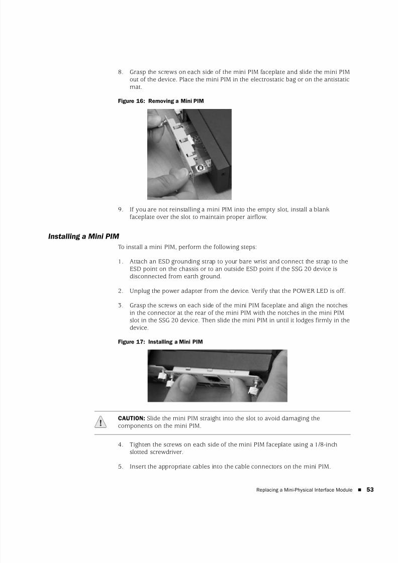
8/3/2019 Cisco Ssg20
http://slidepdf.com/reader/full/cisco-ssg20 53/86
Replacing a Mini-Physical Interface Module 53
8. Grasp the screws on each side of the mini PIM faceplate and slide the mini PIMout of the device. Place the mini PIM in the electrostatic bag or on the antistaticmat.
Figure 16: Removing a Mini PIM
9. If you are not reinstalling a mini PIM into the empty slot, install a blankfaceplate over the slot to maintain proper airflow.
Installing a Mini PIM
To install a mini PIM, perform the following steps:
1. Attach an ESD grounding strap to your bare wrist and connect the strap to theESD point on the chassis or to an outside ESD point if the SSG 20 device isdisconnected from earth ground.
2. Unplug the power adapter from the device. Verify that the POWER LED is off.
3. Grasp the screws on each side of the mini PIM faceplate and align the notchesin the connector at the rear of the mini PIM with the notches in the mini PIMslot in the SSG 20 device. Then slide the mini PIM in until it lodges firmly in thedevice.
Figure 17: Installing a Mini PIM
4. Tighten the screws on each side of the mini PIM faceplate using a 1/8-inchslotted screwdriver.
5. Insert the appropriate cables into the cable connectors on the mini PIM.
CAUTION: Slide the mini PIM straight into the slot to avoid damaging thecomponents on the mini PIM.
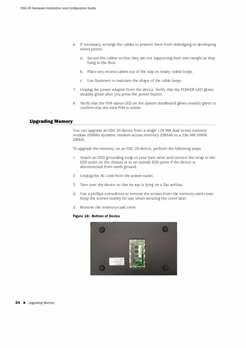
8/3/2019 Cisco Ssg20
http://slidepdf.com/reader/full/cisco-ssg20 54/86
SSG 20 Hardware Installation and Configuration Guide
54 Upgrading Memory
6. If necessary, arrange the cables to prevent them from dislodging or developingstress points:
a. Secure the cables so that they are not supporting their own weight as theyhang to the floor.
b. Place any excess cables out of the way in neatly coiled loops.
c. Use fasteners to maintain the shape of the cable loops.
7. Unplug the power adapter from the device. Verify that the POWER LED glowssteadily green after you press the power button.
8. Verify that the PIM status LED on the system dashboard glows steadily green toconfirm that the mini PIM is online.
Upgrading Memory
You can upgrade an SSG 20 device from a single 128 MB dual in-line memorymodule (DIMM) dynamic random access memory (DRAM) to a 256 MB DIMMDRAM.
To upgrade the memory on an SSG 20 device, perform the following steps:
1. Attach an ESD grounding strap to your bare wrist and connect the strap to theESD point on the chassis or to an outside ESD point if the device isdisconnected from earth ground.
2. Unplug the AC cord from the power outlet.
3. Turn over the device so that its top is lying on a flat surface.
4. Use a phillips screwdriver to remove the screws from the memory-card cover.Keep the screws nearby for use when securing the cover later.
5. Remove the memory-card cover.
Figure 18: Bottom of Device
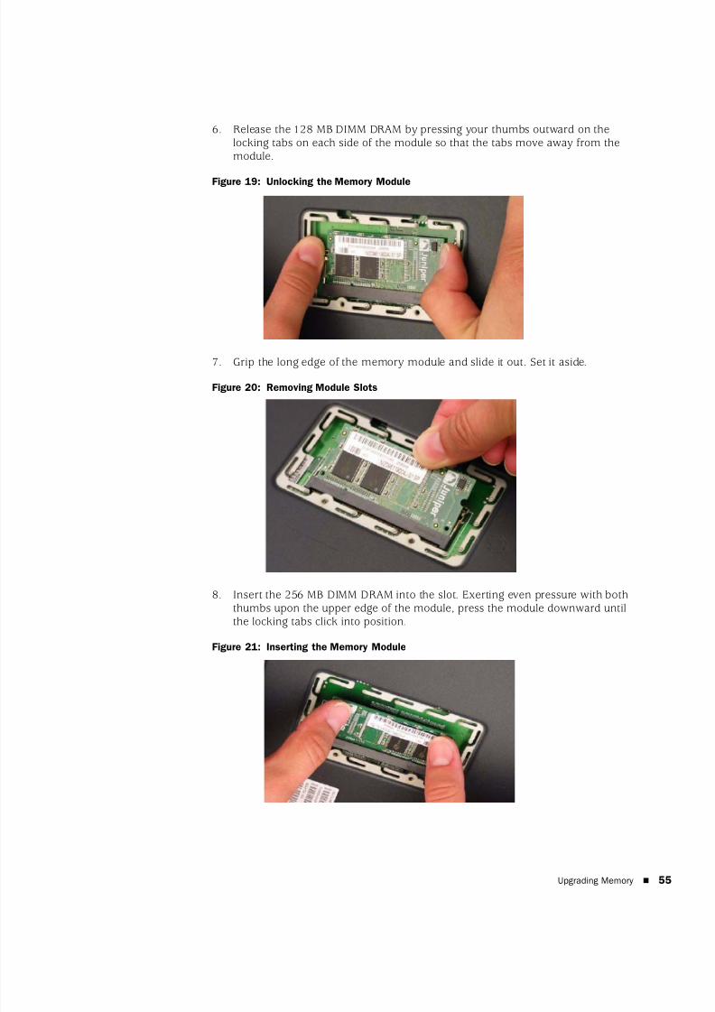
8/3/2019 Cisco Ssg20
http://slidepdf.com/reader/full/cisco-ssg20 55/86
Upgrading Memory 55
6. Release the 128 MB DIMM DRAM by pressing your thumbs outward on thelocking tabs on each side of the module so that the tabs move away from themodule.
Figure 19: Unlocking the Memory Module
7. Grip the long edge of the memory module and slide it out. Set it aside.
Figure 20: Removing Module Slots
8. Insert the 256 MB DIMM DRAM into the slot. Exerting even pressure with boththumbs upon the upper edge of the module, press the module downward untilthe locking tabs click into position.
Figure 21: Inserting the Memory Module

8/3/2019 Cisco Ssg20
http://slidepdf.com/reader/full/cisco-ssg20 56/86
SSG 20 Hardware Installation and Configuration Guide
56 Upgrading Memory
9. Place the memory-card cover over the slot.
10. Use the phillips screwdriver to tighten the screws, securing the cover to thedevice.

8/3/2019 Cisco Ssg20
http://slidepdf.com/reader/full/cisco-ssg20 57/86
57
Appendix A
Specifications
This appendix provides general system specifications for an SSG 20 device. Itcontains the following sections:
“Physical” on page 58
“Electrical” on page 58
“Environmental Tolerance” on page 58
“Certifications” on page 59
“Connectors” on page 60
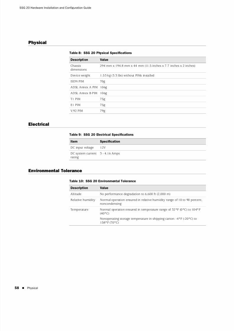
8/3/2019 Cisco Ssg20
http://slidepdf.com/reader/full/cisco-ssg20 58/86
SSG 20 Hardware Installation and Configuration Guide
58 Physical
Physical
Table 8: SSG 20 Physical Specifications
Electrical
Table 9: SSG 20 Electrical Specifications
Environmental Tolerance
Table 10: SSG 20 Environmental Tolerance
Description Value
Chassisdimensions
294 mm x 194.8 mm x 44 mm (11.5 inches x 7.7 inches x 2 inches)
Device weight 1.53 kg (3.3 lbs) without PIMs installed
ISDN PIM 70g
ADSL Annex A PIM 106g
ADSL Annex B PIM 106g
T1 PIM 75g
E1 PIM 75g
V.92 PIM 79g
Item Specification
DC input voltage 12V
DC system currentrating
3 - 4.16 Amps
Description Value
Altitude No performance degradation to 6,600 ft (2,000 m)
Relative humidity Normal operation ensured in relative humidity range of 10 to 90 percent,noncondensing
Temperature Normal operation ensured in temperature range of 32°F (0°C) to 104°F(40°C)
Nonoperating storage temperature in shipping carton: -4°F (-20°C) to158°F (70°C)

8/3/2019 Cisco Ssg20
http://slidepdf.com/reader/full/cisco-ssg20 59/86
Certifications 59
Certifications
Safety CAN/CSA-C22.2 No. 60950-1-03/UL 60950-1 Safety of Information Technology
Equipment
EN 60950-1 (2000) Third Edition Safety of Information Technology Equipment
IEC 60950-1 (1999) Third Edition Safety of Information Technology Equipment
EMC Emissions
FCC Part 15 Class B (USA)
EN 55022 Class B (Europe)
AS 3548 Class B (Australia)
VCCI Class B (Japan)
EMC Immunity
EN 55024
EN-61000-3-2 Power Line Harmonics
EN-61000-3-3 Power Line Harmonics
EN-61000-4-2 ESD
EN-61000-4-3 Radiated Immunity
EN-61000-4-4 EFT
EN-61000-4-5 Surge
EN-61000-4-6 Low Frequency Common Immunity
EN-61000-4-11 Voltage Dips and Sags
ETSI
European Telecommunications Standards Institute (ETSI) EN-3000386-2:Telecommunication Network Equipment. Electromagnetic CompatibilityRequirements; (equipment category–Other than telecommunication centers)
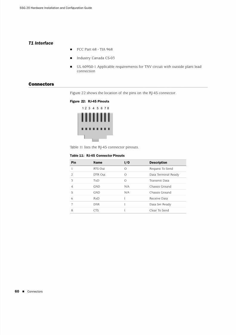
8/3/2019 Cisco Ssg20
http://slidepdf.com/reader/full/cisco-ssg20 60/86
SSG 20 Hardware Installation and Configuration Guide
60 Connectors
T1 Interface
FCC Part 68 - TIA 968
Industry Canada CS-03
UL 60950-1 Applicable requirements for TNV circuit with outside plant leadconnection
Connectors
Figure 22 shows the location of the pins on the RJ-45 connector.
Figure 22: RJ-45 Pinouts
Table 11 lists the RJ-45 connector pinouts.
Table 11: RJ-45 Connector Pinouts
Pin Name I/O Description
1 RTS Out O Request To Send
2 DTR Out O Data Terminal Ready3 TxD O Transmit Data
4 GND N/A Chassis Ground
5 GND N/A Chassis Ground
6 RxD I Receive Data
7 DSR I Data Set Ready
8 CTS I Clear To Send
1 2 3 4 5 6 7 8
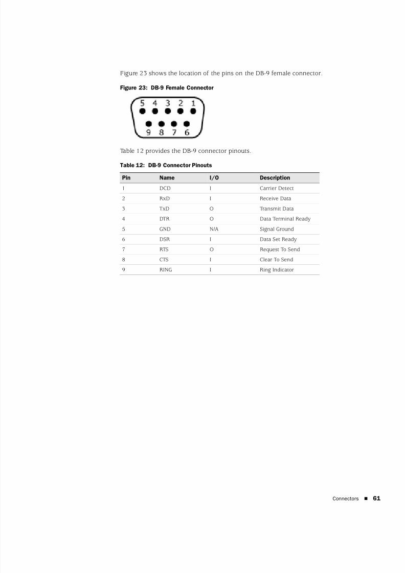
8/3/2019 Cisco Ssg20
http://slidepdf.com/reader/full/cisco-ssg20 61/86
Connectors 61
Figure 23 shows the location of the pins on the DB-9 female connector.
Figure 23: DB-9 Female Connector
Table 12 provides the DB-9 connector pinouts.
Table 12: DB-9 Connector Pinouts
Pin Name I/O Description
1 DCD I Carrier Detect
2 RxD I Receive Data3 TxD O Transmit Data
4 DTR O Data Terminal Ready
5 GND N/A Signal Ground
6 DSR I Data Set Ready
7 RTS O Request To Send
8 CTS I Clear To Send
9 RING I Ring Indicator

8/3/2019 Cisco Ssg20
http://slidepdf.com/reader/full/cisco-ssg20 62/86
SSG 20 Hardware Installation and Configuration Guide
62 Connectors
8/3/2019 Cisco Ssg20
http://slidepdf.com/reader/full/cisco-ssg20 63/86
63
Appendix B
Initial Configuration Wizard
This appendix provides detailed information about the Initial Configuration Wizard(ICW) for an SSG 20 device.
After you have physically connected your device to the network, you can use the
ICW to configure the interfaces that are installed on your device.
This section describes the following ICW windows:
Rapid Deployment Window on page 64
Administrator Login Window on page 64
WLAN Access Point Window on page 65
Physical Interface Window on page 65
ADSL2/2+ Interface Window on page 66
T1 Interface Windows on page 68
E1 Interface Windows on page 73
ISDN Interface Windows on page 75
V.92 Modem Interface Window on page 78
Eth0/0 Interface (Untrust Zone) Window on page 78
Eth0/1 Interface (DMZ Zone) Window on page 79
Bgroup0 Interface (Trust Zone) Window on page 80
Wireless0/0 Interface (Trust Zone) Window on page 81
Interface Summary Window on page 82
Physical Ethernet DHCP Interface Window on page 83
Wireless DHCP Interface Window on page 83
Confirmation Window on page 84
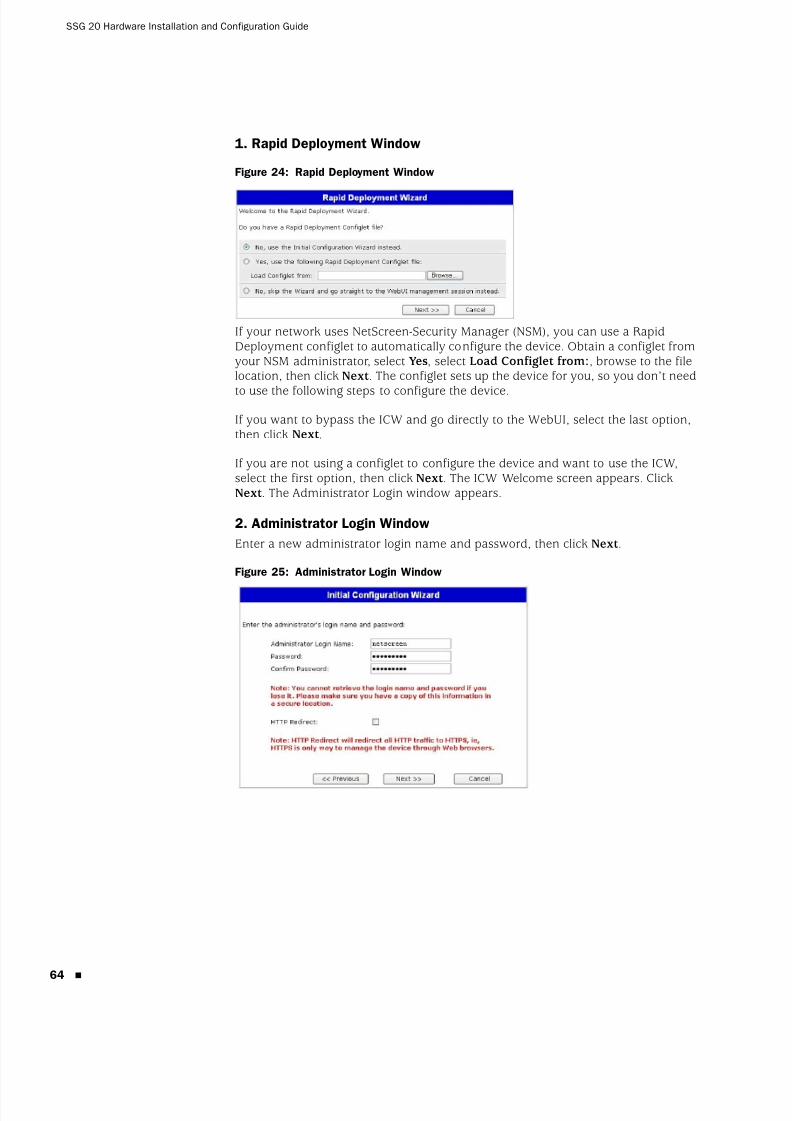
8/3/2019 Cisco Ssg20
http://slidepdf.com/reader/full/cisco-ssg20 64/86
SSG 20 Hardware Installation and Configuration Guide
64
1. Rapid Deployment Window
Figure 24: Rapid Deployment Window
If your network uses NetScreen-Security Manager (NSM), you can use a RapidDeployment configlet to automatically configure the device. Obtain a configlet fromyour NSM administrator, select Yes, select Load Configlet from:, browse to the filelocation, then click Next . The configlet sets up the device for you, so you don’t need
to use the following steps to configure the device.
If you want to bypass the ICW and go directly to the WebUI, select the last option,then click Next .
If you are not using a configlet to configure the device and want to use the ICW,select the first option, then click Next . The ICW Welcome screen appears. ClickNext . The Administrator Login window appears.
2. Administrator Login Window
Enter a new administrator login name and password, then click Next .
Figure 25: Administrator Login Window
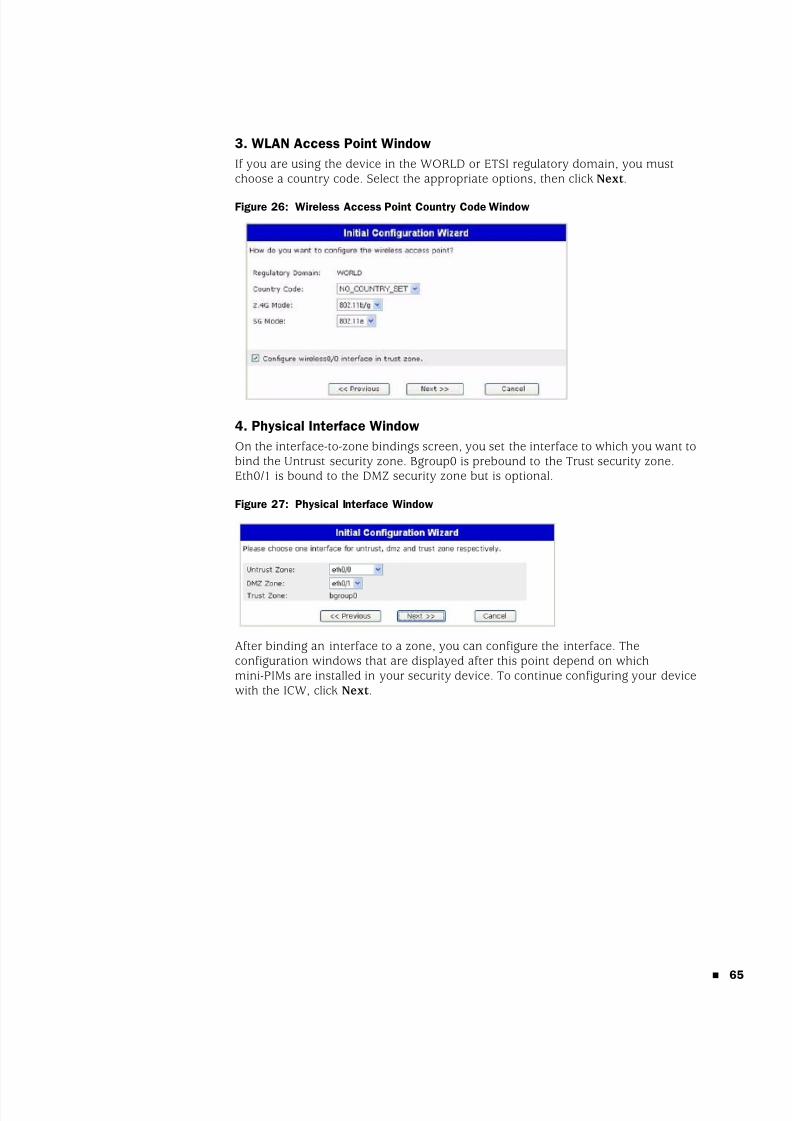
8/3/2019 Cisco Ssg20
http://slidepdf.com/reader/full/cisco-ssg20 65/86
65
3. WLAN Access Point Window
If you are using the device in the WORLD or ETSI regulatory domain, you mustchoose a country code. Select the appropriate options, then click Next .
Figure 26: Wireless Access Point Country Code Window
4. Physical Interface Window
On the interface-to-zone bindings screen, you set the interface to which you want tobind the Untrust security zone. Bgroup0 is prebound to the Trust security zone.Eth0/1 is bound to the DMZ security zone but is optional.
Figure 27: Physical Interface Window
After binding an interface to a zone, you can configure the interface. Theconfiguration windows that are displayed after this point depend on whichmini-PIMs are installed in your security device. To continue configuring your devicewith the ICW, click Next .
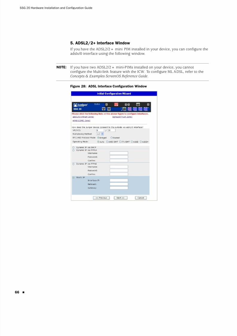
8/3/2019 Cisco Ssg20
http://slidepdf.com/reader/full/cisco-ssg20 66/86
SSG 20 Hardware Installation and Configuration Guide
66
5. ADSL2/2+ Interface Window
If you have the ADSL2/2+ mini PIM installed in your device, you can configure theadslx/0 interface using the following window.
Figure 28: ADSL Interface Configuration Window
NOTE: If you have two ADSL2/2+ mini-PIMs installed on your device, you cannotconfigure the Multi-link feature with the ICW. To configure ML ADSL, refer to theConcepts & Examples ScreenOS Reference Guide.
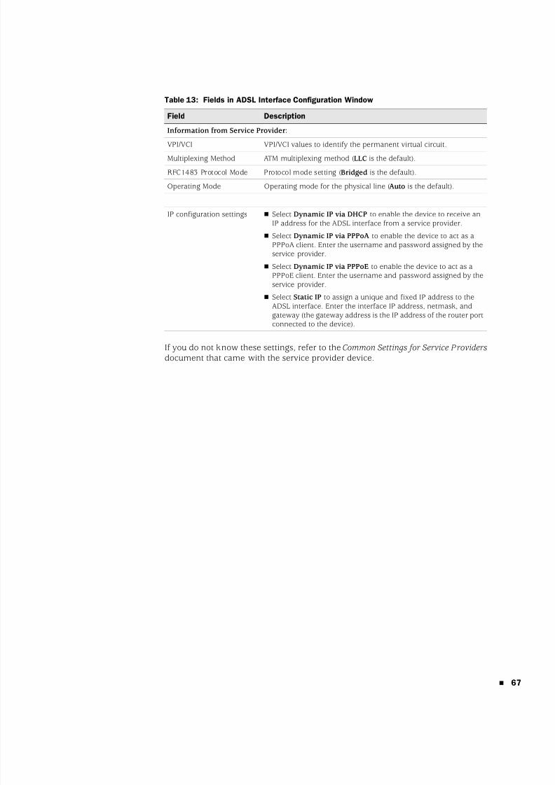
8/3/2019 Cisco Ssg20
http://slidepdf.com/reader/full/cisco-ssg20 67/86
67
Table 13: Fields in ADSL Interface Configuration Window
If you do not know these settings, refer to the Common Settings for Service Providers document that came with the service provider device.
Field Description
Information from Service Provider:
VPI/VCI VPI/VCI values to identify the permanent virtual circuit.
Multiplexing Method ATM multiplexing method (LLC is the default).
RFC1483 Protocol Mode Protocol mode setting (Bridged is the default).
Operating Mode Operating mode for the physical line (Auto is the default).
IP configuration settings Select Dynamic IP via DHCP to enable the device to receive anIP address for the ADSL interface from a service provider.
Select Dynamic IP via PPPoA to enable the device to act as aPPPoA client. Enter the username and password assigned by theservice provider.
Select Dynamic IP via PPPoE to enable the device to act as a
PPPoE client. Enter the username and password assigned by theservice provider.
Select Static IP to assign a unique and fixed IP address to theADSL interface. Enter the interface IP address, netmask, andgateway (the gateway address is the IP address of the router portconnected to the device).
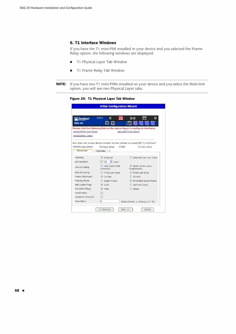
8/3/2019 Cisco Ssg20
http://slidepdf.com/reader/full/cisco-ssg20 68/86
SSG 20 Hardware Installation and Configuration Guide
68
6. T1 Interface Windows
If you have the T1 mini-PIM installed in your device and you selected the FrameRelay option, the following windows are displayed:
T1 Physical Layer Tab Window
T1 Frame Relay Tab Window
Figure 29: T1 Physical Layer Tab Window
NOTE: If you have two T1 mini-PIMs installed on your device and you select the Multi-link option, you will see two Physical Layer tabs.
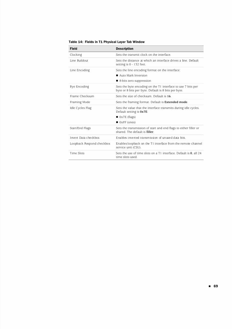
8/3/2019 Cisco Ssg20
http://slidepdf.com/reader/full/cisco-ssg20 69/86
69
Table 14: Fields in T1 Physical Layer Tab Window
Field Description
Clocking Sets the transmit clock on the interface.
Line Buildout Sets the distance at which an interface drives a line. Defaultsetting is 0 - 132 feet.
Line Encoding Sets the line encoding format on the interface:
Auto Mark Inversion
8-bits zero suppression
Bye Encoding Sets the byte encoding on the T1 interface to use 7 bits perbyte or 8 bits per byte. Default is 8 bits per byte.
Frame Checksum Sets the size of checksum. Default is 16.
Framing Mode Sets the framing format. Default is Extended mode.
Idle Cycles Flag Sets the value that the interface transmits during idle cycles.Default setting is 0x7E:
0x7E (flags)
0xFF (ones)
Start/End Flags Sets the transmission of start and end flags to either filler orshared. The default is filler.
Invert Data checkbox Enables inverted transmission of unused data bits.
Loopback Respond checkbox Enables loopback on the T1 interface from the remote channelservice unit (CSU).
Time Slots Sets the use of time slots on a T1 interface. Default is 0, all 24time slots used.
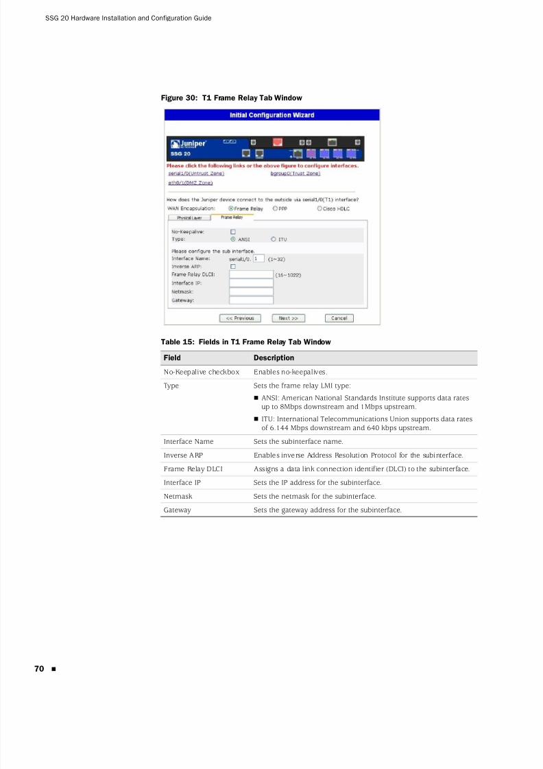
8/3/2019 Cisco Ssg20
http://slidepdf.com/reader/full/cisco-ssg20 70/86
SSG 20 Hardware Installation and Configuration Guide
70
Figure 30: T1 Frame Relay Tab Window
Table 15: Fields in T1 Frame Relay Tab Window
Field Description
No-Keepalive checkbox Enables no-keepalives.
Type Sets the frame relay LMI type:
ANSI: American National Standards Institute supports data ratesup to 8Mbps downstream and 1Mbps upstream.
ITU: International Telecommunications Union supports data ratesof 6.144 Mbps downstream and 640 kbps upstream.
Interface Name Sets the subinterface name.
Inverse ARP Enables inverse Address Resolution Protocol for the subinterface.
Frame Relay DLCI Assigns a data link connection identifier (DLCI) to the subinterface.
Interface IP Sets the IP address for the subinterface.
Netmask Sets the netmask for the subinterface.
Gateway Sets the gateway address for the subinterface.
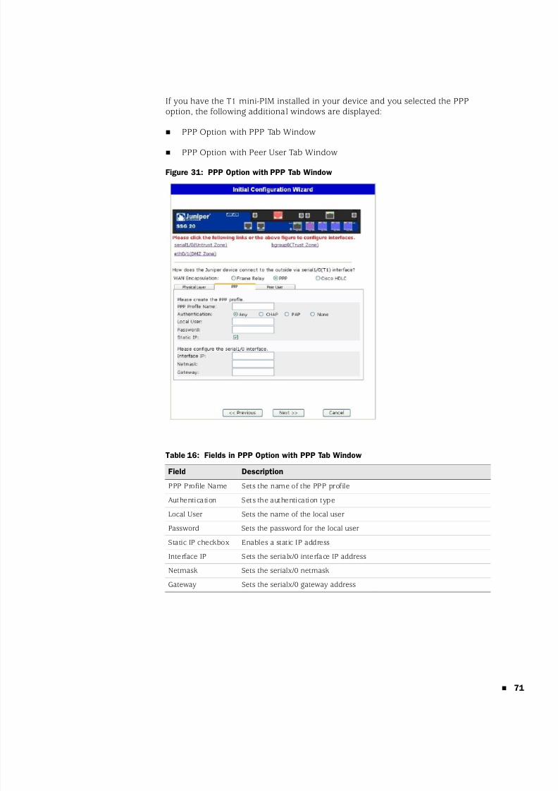
8/3/2019 Cisco Ssg20
http://slidepdf.com/reader/full/cisco-ssg20 71/86
71
If you have the T1 mini-PIM installed in your device and you selected the PPPoption, the following additional windows are displayed:
PPP Option with PPP Tab Window
PPP Option with Peer User Tab Window
Figure 31: PPP Option with PPP Tab Window
Table 16: Fields in PPP Option with PPP Tab Window
Field Description
PPP Profile Name Sets the name of the PPP profile
Authentication Sets the authentication type
Local User Sets the name of the local user
Password Sets the password for the local user
Static IP checkbox Enables a static IP address
Interface IP Sets the serialx/0 interface IP address
Netmask Sets the serialx/0 netmask
Gateway Sets the serialx/0 gateway address
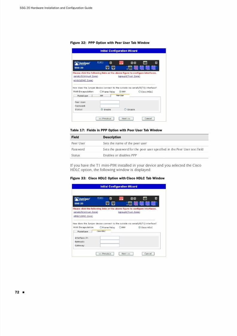
8/3/2019 Cisco Ssg20
http://slidepdf.com/reader/full/cisco-ssg20 72/86
SSG 20 Hardware Installation and Configuration Guide
72
Figure 32: PPP Option with Peer User Tab Window
Table 17: Fields in PPP Option with Peer User Tab Window
If you have the T1 mini-PIM installed in your device and you selected the CiscoHDLC option, the following window is displayed:
Figure 33: Cisco HDLC Option with Cisco HDLC Tab Window
Field Description
Peer User Sets the name of the peer user
Password Sets the password for the peer user specified in the Peer User text field
Status Enables or disables PPP
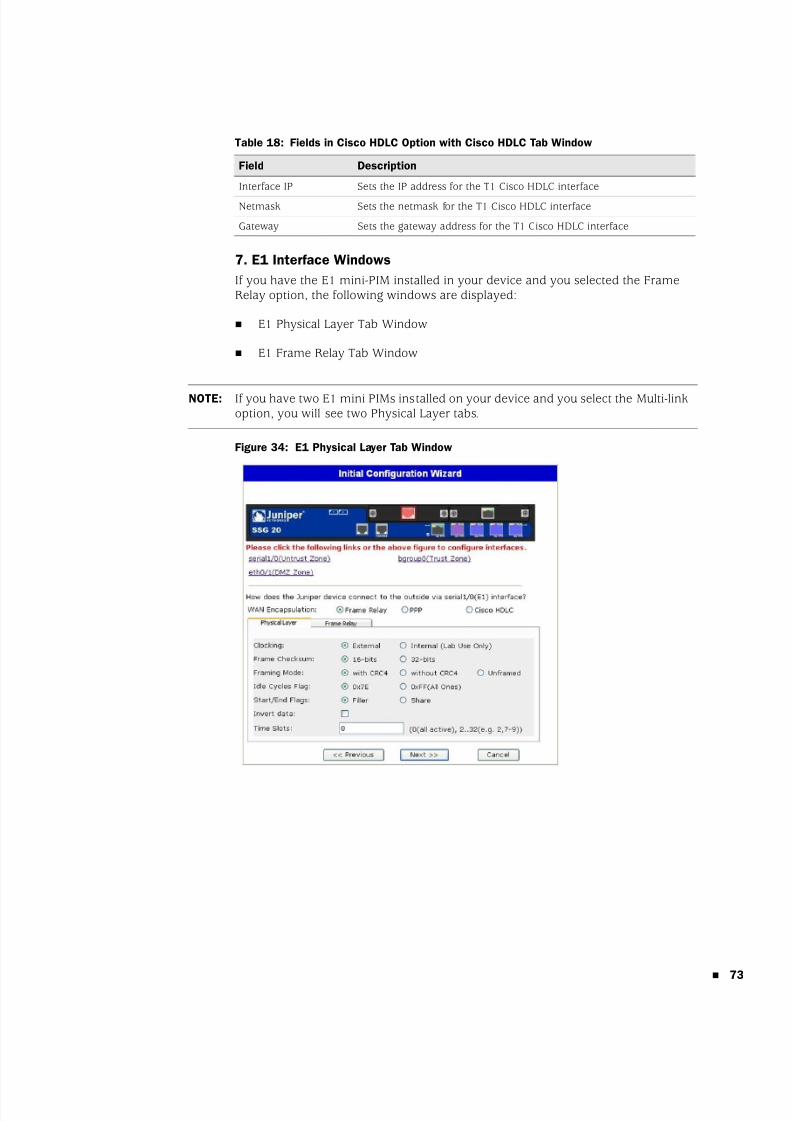
8/3/2019 Cisco Ssg20
http://slidepdf.com/reader/full/cisco-ssg20 73/86
73
Table 18: Fields in Cisco HDLC Option with Cisco HDLC Tab Window
7. E1 Interface Windows
If you have the E1 mini-PIM installed in your device and you selected the FrameRelay option, the following windows are displayed:
E1 Physical Layer Tab Window
E1 Frame Relay Tab Window
Figure 34: E1 Physical Layer Tab Window
Field Description
Interface IP Sets the IP address for the T1 Cisco HDLC interface
Netmask Sets the netmask for the T1 Cisco HDLC interface
Gateway Sets the gateway address for the T1 Cisco HDLC interface
NOTE: If you have two E1 mini PIMs installed on your device and you select the Multi-linkoption, you will see two Physical Layer tabs.

8/3/2019 Cisco Ssg20
http://slidepdf.com/reader/full/cisco-ssg20 74/86
SSG 20 Hardware Installation and Configuration Guide
74
Table 19: Fields in E1 Physical Layer Tab Window
Figure 35: E1 Frame Relay Tab Window
Table 20: Fields in E1 Frame Relay Tab Window
Field Description
Clocking Sets the transmit clock on the interface.
Frame Checksum Sets the size of checksum. Default is 16.
Framing Mode Sets the framing format. Default is without CRC4.
Idle Cycles Flag Sets the value that the interface transmits during idle cycles. Defaultsetting is 0x7E:
0x7E (flags)
0xFF (ones)
Start/End Flags Sets the transmission of start and end flags to either filler or shared.The default is filler.
Invert Data checkbox Enables inverted transmission of unused data bits.
Time Slots Sets the use of time slots on a T1 interface. Default is 0, all 32 timeslots used.
Field Description
No-Keepalive checkbox Enables no-keepalives.
Type Sets the frame relay LMI type:
ANSI: American National Standards Institute supports data ratesup to 8Mbps downstream and 1Mbps upstream.
ITU: International Telecommunications Union supports datarates of 6.144 Mbps downstream and 640 kbps upstream.
Interface Name Sets the subinterface name.
Inverse ARP checkbox Enables inverse Address Resolution Protocol (ARP) for thesubinterface.
Frame Relay DLCI Assigns a DLCI to the subinterface.
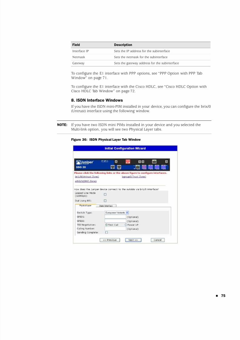
8/3/2019 Cisco Ssg20
http://slidepdf.com/reader/full/cisco-ssg20 75/86
75
To configure the E1 interface with PPP options, see “PPP Option with PPP TabWindow” on page 71.
To configure the E1 interface with the Cisco HDLC, see “Cisco HDLC Option withCisco HDLC Tab Window” on page 72.
8. ISDN Interface Windows
If you have the ISDN mini-PIM installed in your device, you can configure the brix/0(Untrust) interface using the following window.
Figure 36: ISDN Physical Layer Tab Window
Interface IP Sets the IP address for the subinterface
Netmask Sets the netmask for the subinterface
Gateway Sets the gateway address for the subinterface
Field Description
NOTE: If you have two ISDN mini PIMs installed in your device and you selected theMulti-link option, you will see two Physical Layer tabs.
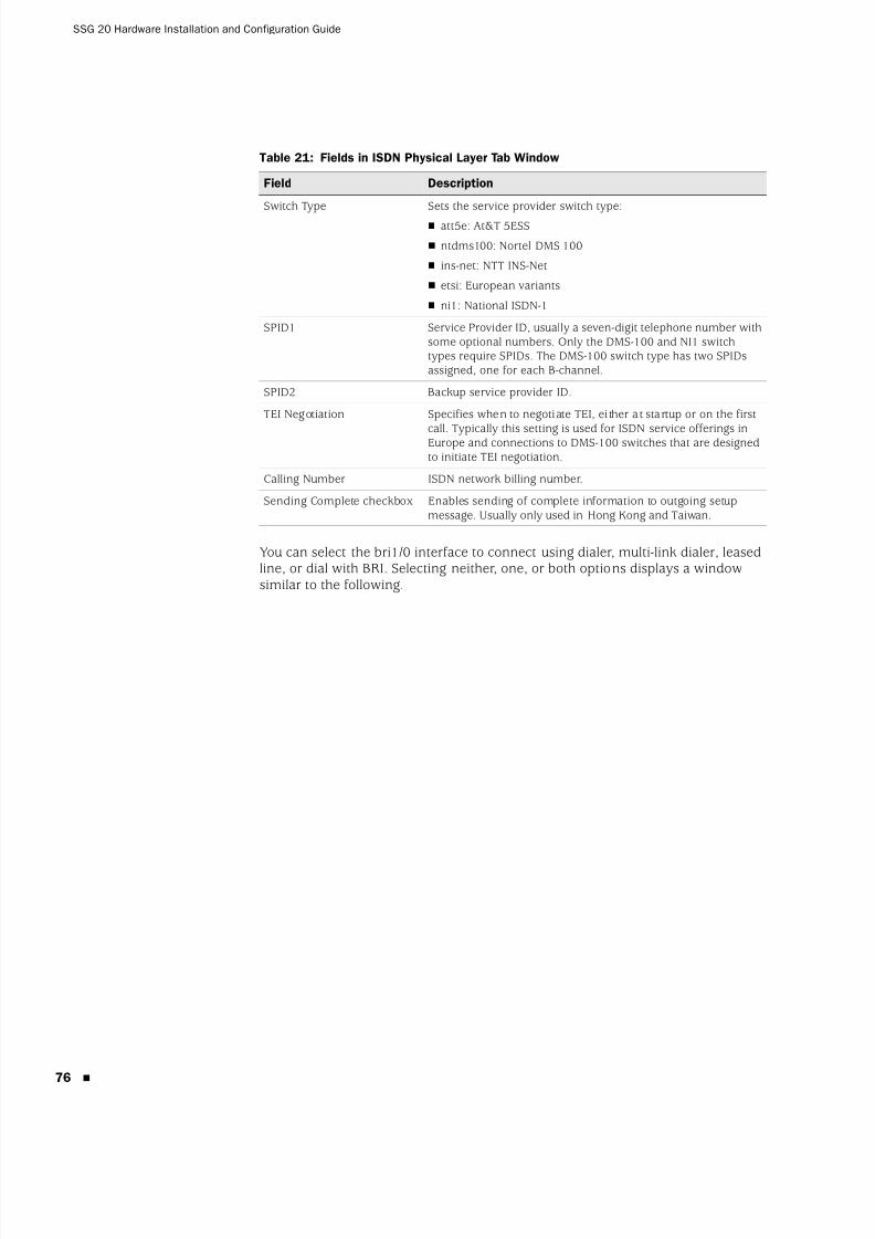
8/3/2019 Cisco Ssg20
http://slidepdf.com/reader/full/cisco-ssg20 76/86
SSG 20 Hardware Installation and Configuration Guide
76
Table 21: Fields in ISDN Physical Layer Tab Window
You can select the bri1/0 interface to connect using dialer, multi-link dialer, leasedline, or dial with BRI. Selecting neither, one, or both options displays a windowsimilar to the following.
Field Description
Switch Type Sets the service provider switch type:
att5e: At&T 5ESS
ntdms100: Nortel DMS 100
ins-net: NTT INS-Net
etsi: European variants
ni1: National ISDN-1
SPID1 Service Provider ID, usually a seven-digit telephone number withsome optional numbers. Only the DMS-100 and NI1 switchtypes require SPIDs. The DMS-100 switch type has two SPIDsassigned, one for each B-channel.
SPID2 Backup service provider ID.
TEI Negotiation Specifies when to negotiate TEI, either at startup or on the first
call. Typically this setting is used for ISDN service offerings inEurope and connections to DMS-100 switches that are designedto initiate TEI negotiation.
Calling Number ISDN network billing number.
Sending Complete checkbox Enables sending of complete information to outgoing setupmessage. Usually only used in Hong Kong and Taiwan.
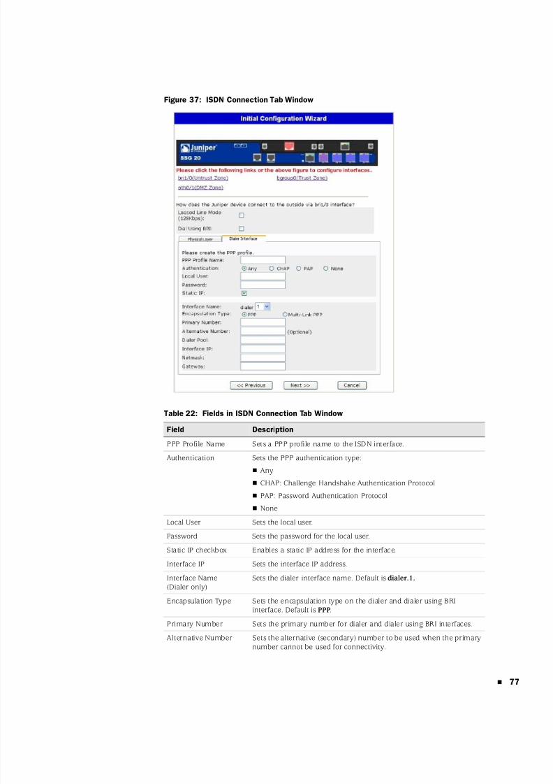
8/3/2019 Cisco Ssg20
http://slidepdf.com/reader/full/cisco-ssg20 77/86
77
Figure 37: ISDN Connection Tab Window
Table 22: Fields in ISDN Connection Tab Window
Field Description
PPP Profile Name Sets a PPP profile name to the ISDN interface.
Authentication Sets the PPP authentication type:
Any
CHAP: Challenge Handshake Authentication Protocol
PAP: Password Authentication Protocol
None
Local User Sets the local user.
Password Sets the password for the local user.
Static IP checkbox Enables a static IP address for the interface.Interface IP Sets the interface IP address.
Interface Name(Dialer only)
Sets the dialer interface name. Default is dialer.1.
Encapsulation Type Sets the encapsulation type on the dialer and dialer using BRIinterface. Default is PPP.
Primary Number Sets the primary number for dialer and dialer using BRI interfaces.
Alternative Number Sets the alternative (secondary) number to be used when the primarynumber cannot be used for connectivity.
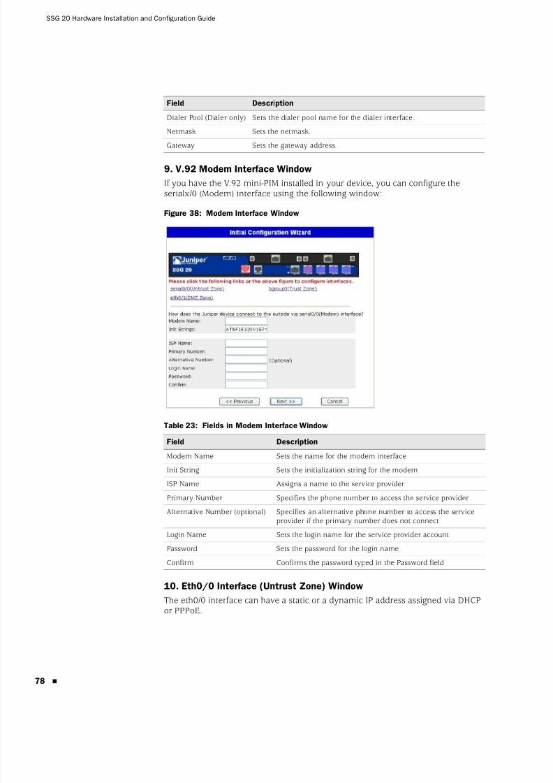
8/3/2019 Cisco Ssg20
http://slidepdf.com/reader/full/cisco-ssg20 78/86
SSG 20 Hardware Installation and Configuration Guide
78
9. V.92 Modem Interface Window
If you have the V.92 mini-PIM installed in your device, you can configure theserialx/0 (Modem) interface using the following window:
Figure 38: Modem Interface Window
Table 23: Fields in Modem Interface Window
10. Eth0/0 Interface (Untrust Zone) Window
The eth0/0 interface can have a static or a dynamic IP address assigned via DHCPor PPPoE.
Dialer Pool (Dialer only) Sets the dialer pool name for the dialer interface.
Netmask Sets the netmask.
Gateway Sets the gateway address.
Field Description
Modem Name Sets the name for the modem interface
Init String Sets the initialization string for the modem
ISP Name Assigns a name to the service provider
Primary Number Specifies the phone number to access the service provider
Alternative Number (optional) Specifies an alternative phone number to access the serviceprovider if the primary number does not connect
Login Name Sets the login name for the service provider account
Password Sets the password for the login nameConfirm Confirms the password typed in the Password field
Field Description
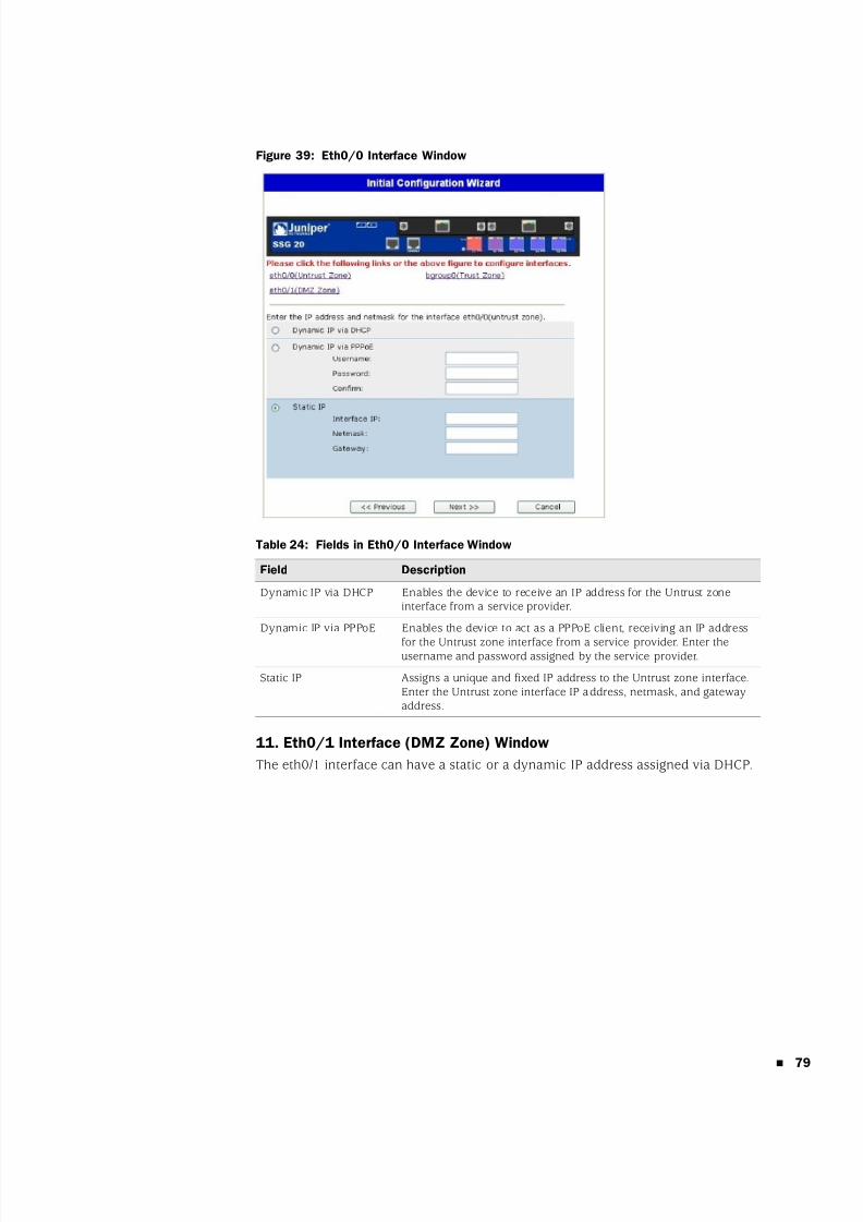
8/3/2019 Cisco Ssg20
http://slidepdf.com/reader/full/cisco-ssg20 79/86
79
Figure 39: Eth0/0 Interface Window
Table 24: Fields in Eth0/0 Interface Window
11. Eth0/1 Interface (DMZ Zone) Window
The eth0/1 interface can have a static or a dynamic IP address assigned via DHCP.
Field Description
Dynamic IP via DHCP Enables the device to receive an IP address for the Untrust zoneinterface from a service provider.
Dynamic IP via PPPoE Enables the device to act as a PPPoE client, receiving an IP address
for the Untrust zone interface from a service provider. Enter theusername and password assigned by the service provider.
Static IP Assigns a unique and fixed IP address to the Untrust zone interface.Enter the Untrust zone interface IP address, netmask, and gatewayaddress.

8/3/2019 Cisco Ssg20
http://slidepdf.com/reader/full/cisco-ssg20 80/86
SSG 20 Hardware Installation and Configuration Guide
80
Figure 40: Eth0/1 Interface Window
Table 25: Fields in Eth0/1 Interface Window
12. Bgroup0 Interface (Trust Zone) Window
The bgroup0 interface can have a static or a dynamic IP address assigned via DHCP.
The default interface IP address is 192.168.1.1 with a netmask of 255.255.255.0 or24.
Figure 41: Bgroup0 Interface Window
Field Description
Dynamic IP via DHCP Enables the device to receive an IP address for the DMZ interfacefrom a service provider.
Static IP Assigns a unique and fixed IP address to the DMZ interface. Enterthe DMZ interface IP and netmask.
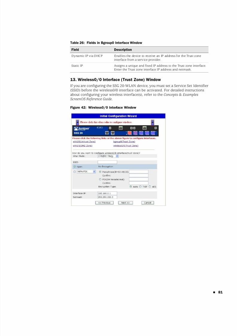
8/3/2019 Cisco Ssg20
http://slidepdf.com/reader/full/cisco-ssg20 81/86
81
Table 26: Fields in Bgroup0 Interface Window
13. Wireless0/0 Interface (Trust Zone) Window
If you are configuring the SSG 20-WLAN device, you must set a Service Set Identifier(SSID) before the wireless0/0 interface can be activated. For detailed instructionsabout configuring your wireless interface(s), refer to the Concepts & ExamplesScreenOS Reference Guide.
Figure 42: Wireless0/0 Interface Window
Field Description
Dynamic IP via DHCP Enables the device to receive an IP address for the Trust zone
interface from a service provider.
Static IP Assigns a unique and fixed IP address to the Trust zone interface.Enter the Trust zone interface IP address and netmask.
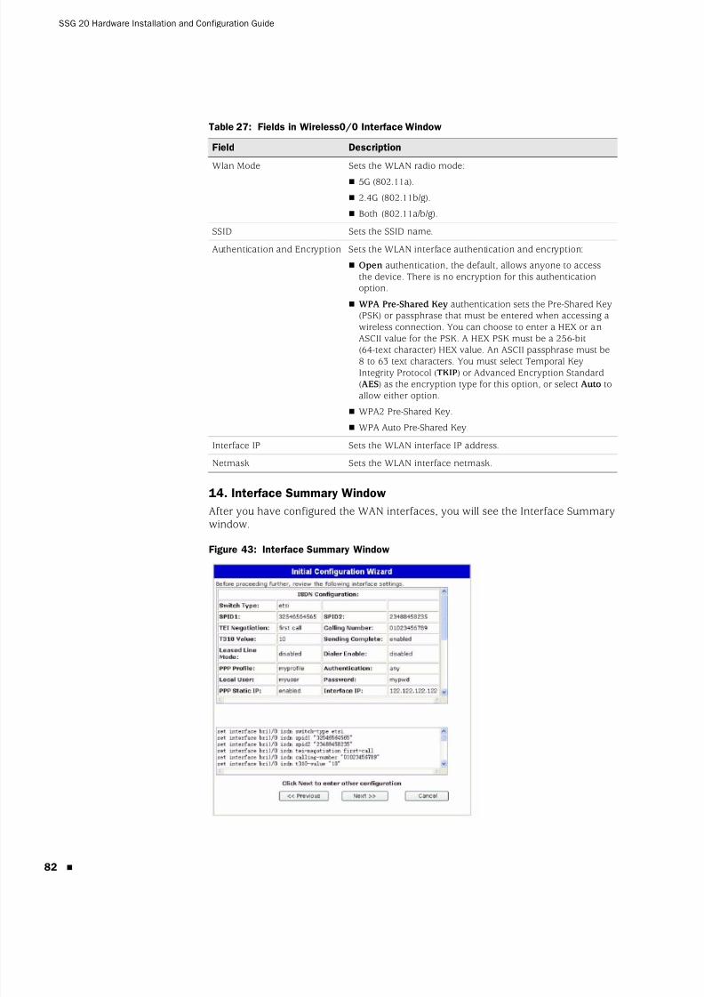
8/3/2019 Cisco Ssg20
http://slidepdf.com/reader/full/cisco-ssg20 82/86
SSG 20 Hardware Installation and Configuration Guide
82
Table 27: Fields in Wireless0/0 Interface Window
14. Interface Summary Window
After you have configured the WAN interfaces, you will see the Interface Summary
window.
Figure 43: Interface Summary Window
Field Description
Wlan Mode Sets the WLAN radio mode:
5G (802.11a).
2.4G (802.11b/g).
Both (802.11a/b/g).
SSID Sets the SSID name.
Authentication and Encryption Sets the WLAN interface authentication and encryption:
Open authentication, the default, allows anyone to accessthe device. There is no encryption for this authenticationoption.
WPA Pre-Shared Key authentication sets the Pre-Shared Key(PSK) or passphrase that must be entered when accessing awireless connection. You can choose to enter a HEX or anASCII value for the PSK. A HEX PSK must be a 256-bit
(64-text character) HEX value. An ASCII passphrase must be8 to 63 text characters. You must select Temporal KeyIntegrity Protocol (TKIP) or Advanced Encryption Standard(AES) as the encryption type for this option, or select Auto toallow either option.
WPA2 Pre-Shared Key.
WPA Auto Pre-Shared Key.
Interface IP Sets the WLAN interface IP address.
Netmask Sets the WLAN interface netmask.
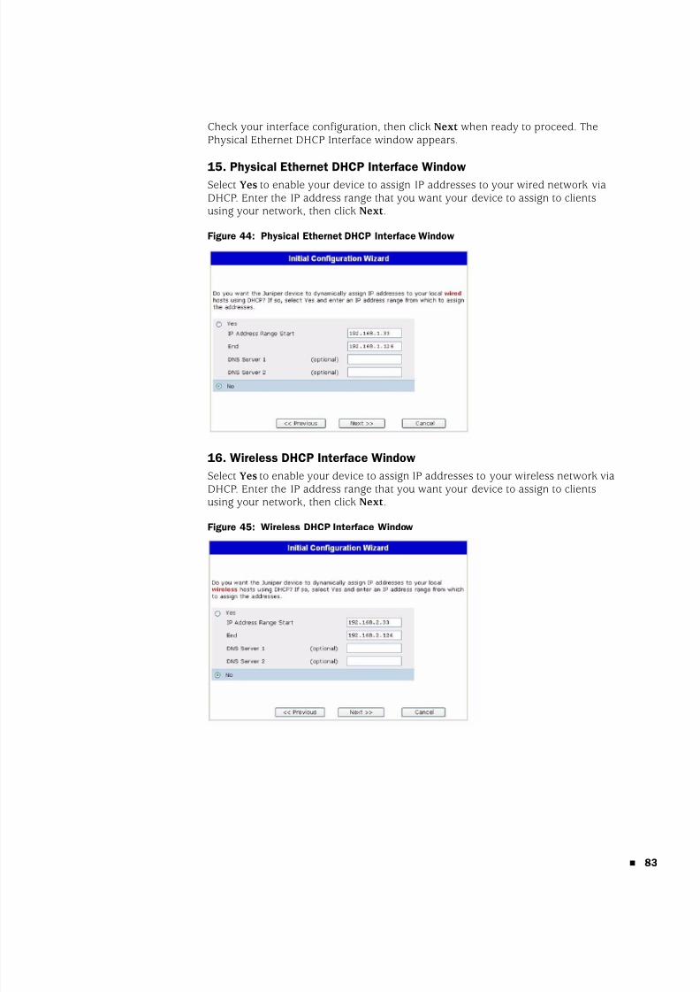
8/3/2019 Cisco Ssg20
http://slidepdf.com/reader/full/cisco-ssg20 83/86
83
Check your interface configuration, then click Next when ready to proceed. ThePhysical Ethernet DHCP Interface window appears.
15. Physical Ethernet DHCP Interface Window
Select Yes to enable your device to assign IP addresses to your wired network viaDHCP. Enter the IP address range that you want your device to assign to clientsusing your network, then click Next .
Figure 44: Physical Ethernet DHCP Interface Window
16. Wireless DHCP Interface Window
Select Yes to enable your device to assign IP addresses to your wireless network viaDHCP. Enter the IP address range that you want your device to assign to clientsusing your network, then click Next .
Figure 45: Wireless DHCP Interface Window
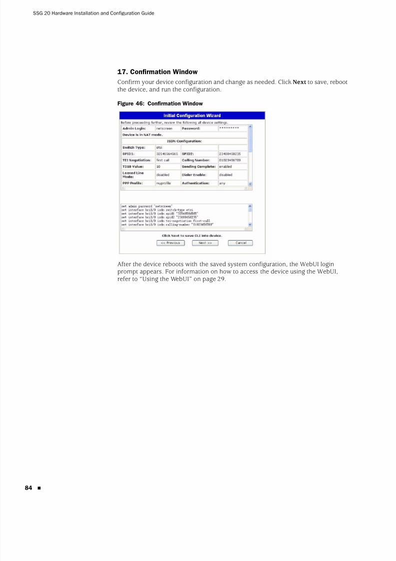
8/3/2019 Cisco Ssg20
http://slidepdf.com/reader/full/cisco-ssg20 84/86
SSG 20 Hardware Installation and Configuration Guide
84
17. Confirmation Window
Confirm your device configuration and change as needed. Click Next to save, rebootthe device, and run the configuration.
Figure 46: Confirmation Window
After the device reboots with the saved system configuration, the WebUI loginprompt appears. For information on how to access the device using the WebUI,refer to “Using the WebUI” on page 29.

8/3/2019 Cisco Ssg20
http://slidepdf.com/reader/full/cisco-ssg20 85/86
Index 85
Index
AAAL5 multiplexing .........................................................41ADSL
configuring interface ...............................................41connecting the cable ...............................................24connecting the port .................................................24
Annex A ..........................................................................24
Annex B ..........................................................................24antennae.........................................................................26ATM Adaptation Layer 5 ...............................................41
Bbackup interface to Untrust zone ................................37
Ccables
ADSL..........................................................................24basic network connections .....................................23serial ..........................................................................24
certificationsEMC (Emissions) ......................................................59EMC Immunity .........................................................59European Telecommunications Standards Institute
(ETSI) ......................................................................59safety .........................................................................59T1 Interface ..............................................................60
configurationadmin name and password....................................33administrative access ..............................................35ADSL 2/2+ mini-PIM ..............................................41backup untrust interface .........................................37bridge groups (bgroup)............................................34date and time ...........................................................34default route .............................................................36
E1 mini-PIM..............................................................46host and domain name ...........................................36ISDN mini-PIM .........................................................45management address..............................................36management services .............................................35T1 mini-PIM..............................................................46USB ............................................................................18V.92 Modem mini-PIM ............................................47virtual circuits...........................................................42VPI/VCI pair ..............................................................42wireless and Ethernet combined ...........................40
wireless authentication and encryption ................38connection, basic network ...........................................23
Ddefault ip addresses.......................................................32
I
ISP IP address and netmask .........................................44
LLEDs
activity link on Ethernet ports ................................13PIM 1 .........................................................................11PIM 2 .........................................................................12POWER .....................................................................11STATUS .....................................................................11
Mmanagement
through a console ....................................................28
through a Telnet connection...................................30through the WebUI ..................................................29memory upgrade procedure ........................................54Mini-PIM
blank faceplate .........................................................52installation ................................................................53removal .....................................................................52
multiplexing, configuring..............................................42
PPoint-to-Point Protocol over ATM
See PPPoAPoint-to-Point Protocol over Ethernet
See PPPoEPPPoA .............................................................................41PPPoE..............................................................................41
Rradio transceivers
WLAN 0 .....................................................................16WLAN 1 .....................................................................16
reset pinhole, using .......................................................49
8/3/2019 Cisco Ssg20
http://slidepdf.com/reader/full/cisco-ssg20 86/86
SSG 20 Hardware Installation and Configuration Guide
Sstatic IP address.............................................................41
UUntrust zone, configuring backup interface...............37
VVirtual Path Identifier/Virtual Channel Identifier
See VPI/VCIVPI/VCI
configuring ...............................................................42values ........................................................................41
Wwireless
antennae ...................................................................26using the default interface ......................................26
WLAN LEDs802.11a.....................................................................12b/g..............................................................................12