Cisco - Rokwell
564
Converged Plantwide Ethernet (CPwE) Design and Implementation Guide Updated: September 9, 2011 Customer Order Number: Text Part Number: OL-21226-01 Document Reference Number: ENET-TD001E-EN-P Rockwell Automation and Cisco Four Key Initiatives: • Common Technology View: A single system architecture, using open, industry standard networking technolo- gies, such as Ethernet, is paramount for achieving the flexibility, visibility, and efficiency required in a competitive manufacturing environment. • Converged Plantwide Ethernet Architectures: These manufacturing focused reference architectures, comprised of the Rockwell Automation Integrated Architecture™ and Cisco’s Ethernet to the Factory, provide users with the foundation for success to deploy the latest technology by addressing topics relevant to both engineering and IT professionals. • Joint Product and Solution Collaboration: Stratix 8000™ Industrial Ethernet switch incorporating the best of Cisco and the best of Rockwell Automation. • People and Process Optimization: Education and services to facilitate Manufacturing and IT convergence and allow successful architecture deploy- ment and efficient operations allowing critical resources to focus on increasing innovation and productivity.
-
Upload
belchior-tito -
Category
Documents
-
view
344 -
download
6
Transcript of Cisco - Rokwell

Rockwell Automation and
Cisco Four Key Initiatives:
• Common Technology View:A single system architecture, using open,
industry standard networking technolo-
gies, such as Ethernet, is paramount for
achieving the flexibility, visibility, and
efficiency required in a competitive
manufacturing environment.
• Converged Plantwide Ethernet
Architectures: These manufacturing focused reference
architectures, comprised of the Rockwell
Automation Integrated Architecture™
and Cisco’s Ethernet to the Factory,
provide users with the foundation for
success to deploy the latest technology
by addressing topics relevant to both
engineering and IT professionals.
• Joint Product and Solution
Collaboration: Stratix 8000™ Industrial Ethernet switch
incorporating the best of Cisco and the
best of Rockwell Automation.
• People and Process Optimization: Education and services to facilitate
Manufacturing and IT convergence and
allow successful architecture deploy-
ment and efficient operations allowing
critical resources to focus on increasing
innovation and productivity.
Converged Plantwide Ethernet (CPwE) Design and Implementation GuideUpdated: September 9, 2011
Customer Order Number: Text Part Number: OL-21226-01
Document Reference Number: ENET-TD001E-EN-P

About the Authors
Paul Didier, Industry Solutions Architect, Enterprise Systems Engineering, Cisco SystemsPaul is an Industry Solutions Architect for Manufacturing. He is responsible for developing solutions for the Manufacturing vertical, including those for Automation and Control systems. Paul is a member of the Open Device Vendor Association's (ODVA) Technical Review Board and has over 20 years of industry experience.
Prior to joining Cisco, Paul was an Associate Partner with a focus on IT Infrastructure at Accenture for 16 years and an IT Manager for SAP for 2 years. He has extensive experience working for Manufacturing, Retail, and Financial Services clients. He has developed and deployed large enterprise IT applications for a range of business functions on a global scale.
Fernando Macias, Technical Marketing Engineer, Enterprise Systems Engineering, Cisco SystemsFernando is a member of the Industry Solutions group at Cisco. As a Technical Marketing Engineer within the Enterprise Solutions Engineering (ESE), he is responsible for developing networking solutions that impact the Manufacturing industry.
With ten years of experience at Cisco, Fernando has developed networking solutions for Cisco's Physical Security business unit and was a member of Advanced Services, where he provided network design support to large customers, including Fortune 50 companies. Fernando also was a Systems Engineer for Cisco's commercial region.
With over 20 years of networking experience, Fernando has also worked for international manufacturing and construction engineering companies. In addition to Masters degrees in Technology Management and Software Engineering, Fernando holds a CCIE#11777 certification in Routing and Switching.
James Harstad, Senior Program Manager, Enterprise Systems Engineering, Cisco SystemsJames is a Program Manager in the Enterprise Systems Engineering group at Cisco. He is responsible for the management, support and contribution of technical marketing content
Prior to joining Cisco, James was a Technical Sales Manager for semiconductor solutions for the Information Technology industry. He has extensive experience in semiconductor design, processing, applications, sales, and marketing. With over 20 years of technology experience, James has demonstrated innovation and leadership for many information technologies and communications companies as exemplified in US Patent 5,289,576.
Rick Antholine, Commercial Engineer, Commercial Engineering, Rockwell AutomationRick is a Commercial Engineer for Rockwell Automation. He is responsible for developing strategic applications for solving real-world customer automation and information problems. He has worked in the IT industry for more than 17 years with a focus on voice and data communications. Rick has been with Rockwell Automation for 14 years and has his CCNA, CCNP, and CCVP certifications.
Scott A. Johnston, Network & Security Services Consultant, Rockwell AutomationScott is a Network & Security Services Consultant for Rockwell Automation. Scott is responsible for Network Infrastructure Design services with a focus on Ethernet. Scott has worked in the industry for 20 years, with 12 years at Rockwell Automation, providing customer centric solutions in a variety of roles including sales support, solution provider, and educator with the last five years dedicated to industrial networking.
iConverged Plantwide Ethernet (CPwE) Design and Implementation Guide
OL-21226-01, ENET-TD001E-EN-P

About the Authors
Sabina Piyevsky, Team Leader, Global Sales and Marketing - Commercial Engineering, Rockwell AutomationSabina is a Commercial Engineering Team Leader for Rockwell Automation. She is responsible for supporting the joint RA/Cisco Manufacturing Convergence initiative and also for the development and coordination of multiple phases of Reference Architecture applications and proof of concept testing. Sabina brings over 20 years of diverse management, manufacturing and design experience in industrial automation control systems engineering. She is a member of the Open Device Vendor Association's (ODVA) EtherNet/IP Infrastructure Special Interest Group (SIG).
Mark Schillace, Sr. Commercial Engineer, Global Sales and Marketing - Commercial Engineering, Rockwell Automation Mark is a Senior Commercial Engineer for Rockwell Automation. Mark is responsible for developing strategic applications to solve real-world customer automation and information problems. Mark has over 16 years of experience designing control systems for various industries such as manufacturing, power, cement, oil and gas, pulp and paper, etc.
Gregory Wilcox, Networks Business Development Manager, Rockwell Automation Gregory leads a multi-company effort to establish tested and validated design guidelines that help manufacturers design and deploy large-scale automation network infrastructures. As a major contributor to the Cisco and Rockwell Automation Alliance, Gregory has advanced the adoption of convergence between industrial and IT networks. Gregory has been designing and implementing industrial network solutions for the past 25 years, with 20 of those years at Rockwell Automation, holding roles of increasing responsibility such as Application Engineer and Solution Architect, resulting in extensive experience in developing control and information solutions for industrial applications. Prior to joining Rockwell Automation, Gregory worked in the Defense industry developing industrial automation and control system solutions for discrete and process applications.
Dan Zaniewski, Senior Commercial Engineer, Rockwell AutomationDan is an Application Engineer in the Commercial Engineering group at Rockwell and is responsible for pre-sale and escalated post sale support of network and controller products. Dan has 15 years of experience in hardware and firmware design for controllers and 20 years of experience in application engineering. Dan has a Master's degree in Electrical Engineering and is a Professional Engineer for the state of Ohio.
Steve Zuponcic, Marketing Architect, Rockwell AutomationSteve Zuponcic is a Marketing Architect in Rockwell Automation's Technology and Architecture organization. He has 30 years of industrial controls experience with special focus on drive and motion control applications and products. Throughout his tenure, Steve has worked in many capacities including Commercial Engineering Manager, Product Marketing, Strategic Marketing and Drives Systems Engineering. Steve Zuponcic serves as the Chair for ODVA's Distributed Motion SIG, which is responsible for the standardization of CIP Motion and CIP Sync technologies.
iiConverged Plantwide Ethernet (CPwE) Design and Implementation Guide
OL-21226-01, ENET-TD001E-EN-P
Converged Plantwide EOL-21226-01, ENET-TD001E-EN-P
C O N T E N T S
Document Organization i-i
C H A P T E R 1 Converged Plantwide Ethernet Overview 1-1
Executive Summary 1-1
Introduction 1-2
Description and Justification 1-2
Target Audience 1-5
Plant Managers and Control Engineers 1-7
Manufacturing IT 1-8
Applications and Services Supported 1-8
CPwE Solution Benefits 1-9
CPwE Solution Features 1-10
Industrial Characteristics 1-11
Interconnectivity and Interoperability 1-13
Real-Time Communication, Determinism, and Performance 1-15
Availability 1-16
Security 1-17
Manageability 1-18
Scalability 1-19
Scope of the CPwE Solution 1-19
Phase 1—Ethernet-to-the-Factory (EttF) 1-20
Phase 2—Converged Plantwide Ethernet (CPwE) 1-20
Industrial Automation and Control System (IACS) 1-21
History of IACS Networks 1-21
IACS Components 1-22
Physical Layer 1-22
Networking Equipment 1-22
IACS Network Devices 1-23
Industrial Computing 1-25
IACS Communication Protocols 1-26
Communication Model 1-26
ithernet (CPwE) Design and Implementation Guide

Contents
IACS Protocol Overview 1-27
Common Industrial Protocol Overview 1-28
C H A P T E R 2 Converged Plantwide Ethernet Solution 2-1
Overview 2-1
Industrial Automation and Control System Reference Model 2-1
Safety Zone 2-2
Cell/Area Zone 2-3
Manufacturing Zone 2-5
Enterprise Zone 2-6
Converged Plantwide Ethernet Architectures 2-7
Network Reference Model 2-9
Access 2-11
Distribution 2-12
Core 2-12
CPwE—Converging Reference Models 2-14
C H A P T E R 3 CPwE Solution Design—Cell/Area Zone 3-1
Overview 3-1
Key Requirements and Considerations 3-3
Industrial Characteristics 3-3
Interconnectivity and Interoperability 3-4
Real-Time Communication, Determinism, and Performance 3-5
Availability 3-7
Security 3-8
Manageability 3-9
Scalability 3-9
Manufacturing Partners, Machine Builders, and System Integrators 3-10
Network Design Recommendations 3-10
Components 3-11
Managed versus Unmanaged Switches 3-12
Industrial Characteristics 3-13
Interconnectivity and Interoperability 3-13
Real-Time Communications 3-14
Availability 3-14
Manageability 3-15
Security 3-16
Scalability 3-16
Component Summary 3-17
iiConverged Plantwide Ethernet (CPwE) Design and Implementation Guide
OL-21226-01, ENET-TD001E-EN-P

Contents
Traffic Flows 3-19
Topology Options and Media Considerations 3-21
Access and Uplinks 3-22
Linear Topology 3-23
Ring Topology 3-25
Redundant Star Topology 3-26
Cell/Area Topology Comparison 3-27
Media Considerations 3-29
Summary Topology and Media Recommendations 3-32
Logical Segmentation and VLANs 3-32
VLAN Overview 3-35
VLAN Design 3-38
Key Segmentation and VLAN Recommendations 3-41
Availability and Network Resiliency 3-41
Resiliency Protocol overview 3-42
Resiliency Design 3-46
Comparison 3-52
Multicast Management 3-54
IGMP Overview 3-56
IGMP Process 3-57
Multicast Traffic Flow 3-59
IGMP Design Considerations 3-63
Quality-of-Service (QoS) 3-63
QoS Background 3-65
QoS Objectives and Application Service Level 3-65
End-to-End Service Levels 3-67
Identification and Marking 3-68
Policing, Queuing and Scheduling 3-70
Security 3-73
Network Infrastructure Device Access 3-73
Resiliency and Survivability 3-75
Network Telemetry 3-76
Other Cell/Area Zone Security Best Practices 3-79
IACS Network Device Protection 3-82
Scalability 3-84
Scalability and Network Resiliency Protocols 3-84
Limitations on the Number of Multicast Groups 3-85
Impact of the Number of Switches on the IACS Network Deterministic Nature 3-85
Impact of the Number of Switches on Network Convergence 3-87
iiiConverged Plantwide Ethernet (CPwE) Design and Implementation Guide
OL-21226-01, ENET-TD001E-EN-P

Contents
Summary 3-88
C H A P T E R 4 CPwE Solution Design—Manufacturing and Demilitarized Zones 4-1
Overview 4-1
Manufacturing Zone 4-1
Demilitarized Zone 4-3
Key Requirements and Considerations 4-4
Industrial Characteristics 4-4
Interconnectivity and Interoperability 4-4
Real-Time Communication, Determinism, and Performance 4-5
Availability 4-7
Security 4-7
Manufacturing Security Policies 4-8
Manageability 4-8
Scalability 4-9
Composition 4-9
Manufacturing Zone IACS Network Design 4-10
Network Components 4-10
Manufacturing Zone Components 4-11
Cost 4-13
Industrial Characteristics 4-13
Performance and Real-Time Communications 4-13
Availability 4-14
Manageability 4-14
Security 4-15
Component Summary 4-15
Traffic Flows 4-20
Topology Options Overview 4-23
Small Manufacturing Zone Topology 4-23
Medium Manufacturing Zone Topology 4-24
Large Manufacturing Zone Topology 4-26
Routing 4-28
Layer 3 Ports 4-28
Selection of a Routing Protocol 4-29
Routing Metric 4-30
Scalability 4-30
Static or Dynamic Routing 4-31
Applying the Routing Protocol 4-32
Logical Segmentation 4-35
ivConverged Plantwide Ethernet (CPwE) Design and Implementation Guide
OL-21226-01, ENET-TD001E-EN-P

Contents
Availability 4-35
Layer 2 Connectivity 4-35
Core Routing and Layer-3 Switching Resiliency 4-36
IP Addressing 4-38
IP Addressing Background 4-38
IP Address Management 4-38
IP Address Allocation 4-42
IP Address Summary 4-44
Security Design 4-45
Server Farm 4-46
Types of Servers 4-46
Security Protection for Servers 4-48
Endpoint Protection with Cisco Security Agent 4-48
Server Farm Access Layer 4-49
Layer 2 Access Considerations 4-49
Spanning VLANs across Access Layer switches 4-49
Layer-2 Adjacency Requirements 4-50
NIC Teaming 4-50
Security and Network Management 4-51
Security Monitoring, Analysis, and Mitigation with CS-MARS 4-52
FactoryTalk 4-52
Demilitarized Zone Network Design 4-55
DMZ Components 4-55
Cost 4-56
Industrial Characteristics 4-56
Performance and Real-Time Communications 4-57
Information Convergence 4-57
Availability 4-60
Manageability 4-60
Security 4-61
Component Summary 4-62
Plant Firewall 4-62
Topology Options 4-63
Firewall Design and Implementation Considerations 4-64
Security Levels on the Cisco ASA Interfaces 4-64
Authenticating Firewall Sessions for User Access to Servers in the DMZ 4-69
Integrating the ASA 5500 Appliance with the Adaptive Inspection Prevention Security Services Module 4-71
vConverged Plantwide Ethernet (CPwE) Design and Implementation Guide
OL-21226-01, ENET-TD001E-EN-P

Contents
C H A P T E R 5 Implementing and Configuring the Cell/Area Zone 5-1
Overview 5-1
Implementing the Cell/Area IACS Network 5-1
Overview 5-2
Recommendation Summary 5-2
Configuration Tools 5-5
Implementation Steps 5-12
Express Setup and Device Manager 5-12
Features Configured Only via CLI 5-12
Implementing the EtherNet/IP Network Modules 5-17
Overview 5-17
EIP Network Module Implementation Tools 5-17
EtherNet/IP Interface Configuration 5-19
C H A P T E R 6 IACS Network Security and the Demilitarized Zone 6-1
Overview 6-1
Introduction 6-1
Cisco SAFE 6-2
Rockwell Automation Integrated Architecture 6-2
Relevant Standards and Frameworks 6-4
ISA-99 Industrial Automation and Control System Security 6-4
Background 6-5
Principles 6-6
Defense-in-Depth 6-6
Modularity and Flexibility 6-6
Service Availability and Resiliency 6-6
Auditable Implementations 6-6
Challenges of Industrial Environments 6-6
Priorities 6-7
Requirements 6-8
Assets to Protect 6-9
Threats 6-10
Impact 6-12
IACS Network Security Framework 6-13
Overview 6-13
Foundational Network Security Considerations 6-15
IACS Network Device Protection 6-15
Cell/Area IACS Network Security 6-15
Manufacturing IACS Network Security 6-16
viConverged Plantwide Ethernet (CPwE) Design and Implementation Guide
OL-21226-01, ENET-TD001E-EN-P

Contents
Demilitarized Zone and the IACS Firewalls 6-16
Remote Access to the IACS Network 6-16
Technical Challenges 6-17
Guiding Principles for Implementing Remote Access 6-18
Use IT-Approved User Access and Authentication Policies and Procedures 6-18
IACS Network Protocols Stay Home 6-19
Control the Applications 6-19
No Direct Traffic 6-19
No Common Protocols or Ports 6-20
Only One Path In or Out 6-20
Remote Access Use Cases 6-20
Role 6-20
Location 6-21
Architectural Approach 6-21
Implementation Details 6-23
Use of Standard IT-Based Remote Enterprise Access—IPSec VPN 6-25
Permissions Limiting Access of Remote Partners 6-26
Use Secure Web Browsers Supporting HTTPS 6-26
Establish SSL VPN Session to Plant DMZ Firewall 6-26
Intrusion Protection/Detection 6-26
Remote Terminal Session to Remote Access Server 6-27
IACS Applications on Remote Access Server 6-27
Segment and Inspect Traffic to and from the Remote Access Server 6-27
Organizational Considerations 6-27
C H A P T E R 7 Testing the CPwE Solution 7-1
Overview 7-1
Introduction 7-1
Test Objective 7-1
Test Equipment 7-2
Network Equipment 7-2
Network Topology 7-2
IACS Equipment 7-4
Test Approach 7-6
Network Resiliency 7-7
Application-Level Latency and Jitter (Screw-to-Screw) 7-14
Test Execution 7-19
Network Resiliency 7-19
viiConverged Plantwide Ethernet (CPwE) Design and Implementation Guide
OL-21226-01, ENET-TD001E-EN-P

Contents
Test Cases 7-20
Application-level Latency and Jitter 7-26
Test Results Summary 7-26
C H A P T E R 8 CIP Motion 8-1
Introduction 8-1
EtherNet/IP for Motion Control 8-2
CIP Motion Uses Standard, Unmodified Ethernet 8-2
Traditional Approach to Motion Control Networking 8-3
EtherNet/IP Solves Real-time Motion Control Differently 8-4
CIP Sync for Real-Time Motion Control 8-5
Prioritization Services—QoS 8-5
QoS Principles and Operation 8-6
Mapping CIP Traffic to DSCP and 802.1D 8-8
QoS Support in the Infrastructure 8-9
QoS Support in the Rockwell Automation Embedded Switch Technology (DLR and Linear Topologies) 8-10
EtherNet/IP Embedded Switch Technology 8-10
CIP Motion Reference Architectures 8-11
Linear Topologies 8-11
Basic Linear Topologies 8-11
Linear/Star Topology 8-13
Star/Linear Topology 8-14
Linear Topology Reference Architectures Under Test 8-15
DLR Topology 8-18
Mixed Star/Ring Topology 8-20
DLR Topology Reference Architectures Under Test 8-21
Star Topology 8-25
Star Topology Reference Architectures Under Test 8-26
CIP Motion Reference Architecture Testing 8-28
Test Criteria 8-29
Ixia Network Traffic Generator Configuration 8-33
Test Results 8-33
Design Recommendations 8-37
Time Accuracy as a Function of the Application 8-38
Detailed Test Results 8-40
Linear Architecture 8-40
Star Architecture 8-49
Device-Level Ring (DLR) Architecture 8-57
viiiConverged Plantwide Ethernet (CPwE) Design and Implementation Guide
OL-21226-01, ENET-TD001E-EN-P

Contents
C H A P T E R 9 CIP Sync Sequence of Events 9-1
Introduction 9-1
Technology Overview 9-2
SOE Applications—Traditional vs. CIP Sync Approach 9-2
Traditional Approach to Time Synchronization 9-2
CIP Sync: Using EtherNet/IP and Precision Time Protocol for Real-Time Synchronization 9-4
Real-Time Synchronization in Logix Architecture 9-7
Rockwell Automation Devices That Support CIP Sync 9-7
Difference between the 1588 PTP and ControlLogix Clock Synchronization Resolution 9-8
Sequence of Events (SOE) Reference Architecture Testing 9-10
Test Criteria 9-11
Calculating Chassis-based vs. Remote Modules Timestamping Accuracy 9-12
Reference Architectures Test Results Summary 9-16
Architecture 1—Star Topology (Using Stratix Switches) 9-16
Architecture 2—Linear Topology (Using Embedded Dual-Port Ethernet Technology) 9-19
Architecture 3—Ring Topology (Device Level Ring Technology) 9-20
Architecture 4—Multiple Star Topology 9-22
Architecture 5—Star Topology 9-26
Design Recommendations 9-29
Detailed Test Configuration and Results 9-30
Test Phase I—No Load Test 9-30
Test Phase 2—Loading 1756-EN2TR Modules to ~80 Percent 9-31
Test Phase 3—Loading Network Bandwidth by Using the Ixia PC 9-33
Tests Performed 9-34
Detailed Test Results 9-34
Architecture 1—Star Topology (Using Stratix Switches) 9-34
Architecture 2—Linear Topology (Using Devices With Embedded Dual-Port Ethernet Technology) 9-45
Architecture 3—Ring Topology (Device Level Ring Technology) 9-45
Architecture 4—Multiple Star Topology (Separated Network Segments Using the 1756-EN2T Modules in Boundary Clock Mode) 9-49
Architecture 5—Star Topology (Propagating PTP Packets across Different VLANs Using the Stratix 8300 in Boundary Clock Mode) 9-65
C H A P T E R 10 DHCP Persistence in the Cell/Area Zone 10-1
Introduction 10-1
ixConverged Plantwide Ethernet (CPwE) Design and Implementation Guide
OL-21226-01, ENET-TD001E-EN-P
Contents
Using DHCP Persistence to Replace a Failed IACS Device 10-2
Using DHCP Persistence to Provision a New IACS Device 10-2
Brief Technology Overview of DHCP 10-3
Address Allocation in IACS Networks 10-3
DHCP Address Allocation (Handshake) Process 10-3
Methods of IP Allocation in DHCP 10-4
DHCP vs. BOOTP 10-4
DHCP Persistence Reference Architectures Testing 10-6
Test Criteria 10-7
Test Configuration 10-8
Testing Procedure 10-9
Test Results 10-10
DHCP Persistence Design Recommendations for IACS Devices 10-10
DHCP Persistence Configuration Techniques 10-11
DHCP Persistence Topology Considerations 10-11
Linear Topology 10-12
Star Topology 10-13
Ring Topology 10-14
Redundant Star Topology 10-15
A P P E N D I X A Key Terms and Definitions A-1
A P P E N D I X B Test Result Analysis B-1
Impact of the Number of Switches (RMC8 vs. RMC16) B-2
Spanning Tree Protocol Comparison (RMC8 vs. RPC8) B-5
Topology/Resiliency Protocol Analysis B-7
Topology/Resiliency Protocol Analysis—Copper Uplinks (RMC8, SMC8, SEC8, SFC8) B-7
Topology/Resiliency Protocol Analysis—Fiber Uplinks (RMF8, SMF8, SEF8, SFF8) B-9
Media Analysis—Copper vs Fiber (RMC8 vs. RMF8 & SMC8 vs. SMF8) B-15
End-Devices (MAC Addresses) Impact Analysis B-18
End-Device Impact on Network Convergence for Spanning Tree Test Suites B-18
End-Device Impact on Network Convergence for EtherChannel and FlexLinks Test Suites B-22
Restore Impact Analysis B-25
Application Latency (Screw-to-Screw) Analysis B-26
xConverged Plantwide Ethernet (CPwE) Design and Implementation Guide
OL-21226-01, ENET-TD001E-EN-P

Contents
A P P E N D I X C Complete Test Data C-1
Test Suite Summary C-1
RMC8 Test Results C-2
RMC16 Test Results C-9
RPC8 Test Results C-13
RMF8 Test Results C-18
SMC8 Test Results C-21
SMF8 Test Results C-24
SEC8 Test Results C-27
SEF8 Test Results C-31
SFF8 Test Results C-34
SFC8 Test Results C-37
Application Latency (Screw-to-Screw) Test Results C-41
A P P E N D I X D Configurations D-1
Express Setup D-1
Stratix 8000 D-1
IE 3000 with Recommended System Setup Enabled D-6
Smartports D-10
Stratix 8000 D-10
Automation Device D-10
Automation Device with QoS D-10
Desktop for Automation D-11
Switch for Automation D-12
Router for Automation D-12
Phone for Automation D-13
Wireless for Automation D-14
Port Mirroring D-14
None D-14
IE 3000 D-14
IE Desktop D-14
IE Switch D-15
IE Router D-15
IE Phone D-16
IE Wireless D-17
Cisco EtherNet/IP D-17
Diagnostics D-18
None D-18
xiConverged Plantwide Ethernet (CPwE) Design and Implementation Guide
OL-21226-01, ENET-TD001E-EN-P

Contents
A P P E N D I X E Reference Documents E-1
About Cisco Validated Design (CVD) Program E-2
xiiConverged Plantwide Ethernet (CPwE) Design and Implementation Guide
OL-21226-01, ENET-TD001E-EN-P

Preface
The Converged Plantwide Ethernet (CPwE) Design and Implementation Guide represents a collaborative development effort from Cisco Systems and Rockwell Automation. It is built on, and adds to, design guidelines from the Cisco Ethernet-to-the-Factory (EttF) solution and the Rockwell Automation Integrated Architecture™. The CPwE solution is designed for industrial Ethernet applications. Although CPwE is applicable to multiple industries, this Design and Implementation Guide (DIG) focuses on the manufacturing industry.
For more information about the EttF solution, refer to the following URL:
http://www.cisco.com/en/US/docs/solutions/Verticals/EttF/EttFDIG.html
For more information about the Rockwell Automation Integrated Architecture, refer to the following URL:
http://www.ab.com/networks/architectures.html
Document OrganizationThe CPwE DIG contains the following chapters and appendices:
Chapter or Appendix Description
Chapter 1, “Converged Plantwide Ethernet Overview” Provides an overview of the business need, justification, benefits, and features of the Cisco and Rockwell Automation joint CPwE solution.
Chapter 2, “Converged Plantwide Ethernet Solution” Provides an overview of the Converged Plantwide Ethernet (CPwE) solution architecture, which describes the various systems, components, and their relation to each other to provide context to the networking function and technical requirements.
Chapter 3, “CPwE Solution Design—Cell/Area Zone” Describes the key requirements and technical considerations for the Cell/Area zone and related Industrial Automation and Control System (IACS) applications.
iConverged Plantwide Ethernet (CPwE) Design and Implementation Guide
OL-21226-01, ENET-TD001E-EN-P

PrefaceDocument Organization
Chapter 4, “CPwE Solution Design—Manufacturing and Demilitarized Zones”
Provides an overview and basic design considerations for the Manufacturing and Demilitarized zones of the CPwE architecture.
Chapter 5, “Implementing and Configuring the Cell/Area Zone”
Describes the configurations and configuration options to implement the recommendations and best practices described in Chapter 3, “CPwE Solution Design—Cell/Area Zone.”
Chapter 6, “IACS Network Security and the Demilitarized Zone”
Describes the network security for the IACS network protecting the systems, applications, infrastructure, and end-devices.
Chapter 7, “Testing the CPwE Solution” Describes the test plans and environment used to validate the key concepts outlined in the CPwE solution.
Chapter 8, “CIP Motion” Describes the implementation of CIP Motion on EtherNet/IP and extends the design recommendations described in Chapter 3, “CPwE Solution Design—Cell/Area Zone” and Chapter 5, “Implementing and Configuring the Cell/Area Zone.”
Chapter 9, “CIP Sync Sequence of Events” Describes the implementation of CIP Sync time synchronization on EtherNet/IP and extends the design recommendations described in Chapter 3, “CPwE Solution Design—Cell/Area Zone,” and Chapter 5, “Implementing and Configuring the Cell/Area Zone.”
Chapter 10, “DHCP Persistence in the Cell/Area Zone” Describes the implementation of Dynamic Host Configuration Protocol (DHCP) persistence on an EtherNet/IP network.
Appendix A, “Key Terms and Definitions” Lists and defines the key terms used in this DIG.
Appendix B, “Test Result Analysis” Provides comparison and analysis of the test results in Appendix C “Complete Test Data.”
Appendix C, “Complete Test Data” Provides the data generated from the CPwE solution testing.
Appendix D, “Configurations” Provides configurations for key components of the CPwE solution.
Appendix E, “Reference Documents” Lists reference documents for additional information.
Chapter or Appendix Description
iiConverged Plantwide Ethernet (CPwE) Design and Implementation Guide
OL-21226-01, ENET-TD001E-EN-P

Converged Plantwide Ethernet (CPwOL-21226-01, ENET-TD001E-EN-P
C H A P T E R 1
Converged Plantwide Ethernet OverviewExecutive Summary Faced with internal pressures to cut costs and external demands for better products and services, manufacturers are realizing the business benefits of converged Manufacturing and Enterprise networks, such as the following:
• Globalize operations through IT integration with Industrial Automation and Control Systems, enabling plant-to-business network convergence, thus driving strategic business decisions that are backed by real-time data from IACS.
• Visibility into the IACS for optimized supply chain management.
• Provide visibility into the plant floor for optimized supply chain management.
• Improve operational costs and efficiency through ease-of-use features and capabilities of common tools that improve productivity for plant maintenance and engineering personnel.
• Reduce mean-time-to-repair (MTTR) and increase overall equipment effectiveness (OEE) through secure remote access for employees and partners.
• Mitigate risks by improving network uptime and equipment availability with industry-leading security features and a defense-in-depth approach that protect critical manufacturing assets.
• Shorten lead times of deploying new products as communication and collaboration between business decision makers and plant personnel become richer and easier through converged networks.
• Reduced costs and improved asset utilization by relying on standard Ethernet and IP networking technology for IACS networks, such as personnel training, spares and development tools.
• Simplified management through better integration with Industrial Automation and Control System applications and use of remote management capabilities.
• Realize productivity improvements as ready-to-deploy collaboration technology (voice-over-IP phones and IP security cameras) become more common in IACS networks.
The key industrial Ethernet applications are Industrial Automation and Control Systems (IACS) networks. For the purpose of this Design and Implementation Guide (DIG), the term IACS is generically used to represent industrial systems such as: Industrial Automation and Control Systems, Process Automation System, Process Control System, Supervisory Control and Data Acquisition. IACS benefit greatly from the transition to modern Ethernet and IP networking
1-1E) Design and Implementation Guide

Chapter 1 Converged Plantwide Ethernet Overview Introduction
technologies from the vendor-optimized networks typically used in the past. New services and streamlined efficiency result when the information contained within the IACS is available and shared throughout the larger enterprise. Access to existing manufacturing information may be gated by disparate, proprietary, and closed systems as the move to open systems continues. Manufacturers and their industrial suppliers are discovering that standard communication and uniform networking of an IACS is the key to optimized services, greater visibility, and lower total cost of ownership (TCO). They are starting to embrace standard information technology, particularly standard Ethernet and standard IP, for IACS networking environments.
Although IACS vendors recognize that Ethernet and the IP protocol suite are the de-facto networking standards in IACS environments, full adoption of standard Ethernet and IP is still very much a work in progress. The pace of progress can be attributed to the aversion to disrupting existing systems, the accounting realities of fully-depreciated assets, legacy migration and the general ebb and flow of manufacturing investment cycles. Despite these challenges, industrial Ethernet is being deployed today on a broad scale. The rate of global adoption will continue to increase with greater application and end-device support from an increasing number of industrial equipment suppliers offering industrial Ethernet products.
Cisco and Rockwell Automation believe standard Ethernet and IP networking technology offers value inside industrial operations when the technology is part of larger integrated, IACS architectures. Cisco calls this the Ethernet-to-the-Factory (EttF) architecture. Rockwell Automation calls this Integrated Architecture. The Converged Plantwide Ethernet (CPwE) architecture joins these architectures.
The purpose of the CPwE architecture, a set of manufacturing focused reference architectures, is to help accelerate the successful deployment of standard networking technologies and convergence of manufacturing and enterprise/business networks. This solution architecture and relevant design and implementation guidelines will help provide confidence and background necessary to successfully deploy standard networking technologies and integrate IACS and business networks. This CPwE solution architecture must be tailored to support IACS. By adopting the solution architecture, the manufacturing process will operate at higher levels of performance, efficiency and uptime than under the previous solutions. At the same time, the solution must also safely and securely integrate the IACS into the broader manufacturing environment; only at this point will all the benefits be available to the manufacturing enterprise.
Introduction
Description and JustificationManufacturing companies are increasingly expanding their global operations to address new opportunities and reduce operational costs. They are also seeking to continuously improve efficiency and drive down costs for existing facilities and processes. In fact, a recent study by Aberdeen (May 2009) noted that reducing costs is identified as by far the greatest business pressure of 63 percent of manufacturers.
Achieving these goals of globalization and operations excellence requires increased connectivity between IACS and business systems for real-time visibility to information and effective collaboration to:
• Ensure consistent quality and performance across global operations
• Balance manufacturing with demand to optimize material usage and asset utilization
• Improve and meet regulatory compliance
1-2Converged Plantwide Ethernet (CPwE) Design and Implementation Guide
OL-21226-01, ENET-TD001E-EN-P

Chapter 1 Converged Plantwide Ethernet Overview Introduction
• Implement more flexible and agile manufacturing operations to respond to rapidly changing market conditions
• Meet demanding requirements and metrics for on-time delivery through reduced MTTR and increased OEE
• Reduce the cost of design, deployment, and support of manufacturing and IT systems at global manufacturing plants.
• Improve response to events that occur on the plant floor, regardless of location IACS manufacturers are currently falling short of these objectives. The key to resolving this problem is better access to information. With a constant flow of data, companies can develop more efficient ways to connect globally with suppliers, employees, and partners, and to more effectively meet the needs of end customers.
The key to achieving these goals is better access to information. With a constant flow of data, manufacturers can develop more efficient ways to connect globally with suppliers, employees, and partners, and to more effectively meet the needs of their customers.
The industrial manufacturing environment was very similar to the IBM legacy mainframe environments of the mid 1990s. Although these legacy industrial systems are functional, they are costly to maintain, difficult to connect, and slow to evolve. With their IACS-optimized protocols, specific operating requirements, and separate staffs, manufacturers were also struggling to evolve. Whether their IACS is discrete, process, batch, or hybrid, manufacturers need their systems to interact in real-time with the other enterprise applications, supply chain partners, and end customers. To accomplish this, manufacturers are converging their IACS networks with their enterprise networks. When doing this, manufacturers encounter a number of challenges, such as the following:
• Reliability—As manufacturing operations become globally integrated, manufacturers are challenged to provide consistent access to data while making the manufacturing environment flexible. Security, availability, and asset use are critically important to manufacturing companies because IACS equipment is mission-critical, and efficiency is important to remain competitive.
• Cost—Legacy IACS, although often fully depreciated in existing manufacturing environments, can be difficult to integrate with the enterprise and can be costly to operate due to the multiple networks in use that require management, training, integration, gateways, spares, etc.
• Product design integration—Limited access to local subject-matter experts constrain collaborative manufacturing, impacting the ability to quickly respond to events, collaborate with engineering on new products and increasing cost to resolve problem.
• Service integration—In an effort to provide differentiated service, manufacturers are struggling to create systems to capture and incorporate genealogy data about their products.
• Data interaction and management—Incorporating real-time plant productivity and operational data into manufacturing execution systems (MES), customer relationship management (CRM), supply chain management (SCM), and other enterprise resource planning (ERP) systems restrict and constrain the ongoing move to service-oriented architectures.
• Partner connections—With an aging and decreasing workforce and increased manufacturing complexity, manufacturers are trying to find ways to leverage relationships with IACS vendors to support their plant floor applications.
These challenges are pushing manufacturers to adopt standard Ethernet and IP network technologies throughout the manufacturing environment. By moving to standard network technologies, manufacturers can:
1-3Converged Plantwide Ethernet (CPwE) Design and Implementation Guide
OL-21226-01, ENET-TD001E-EN-P

Chapter 1 Converged Plantwide Ethernet Overview Introduction
• Realize significant cost savings—Standard Ethernet and IP network technology with a broader base of IACS suppliers, resources and innovation are more likely than existing IACS networking technologies to give manufacturers a significantly lower total cost-of-ownership (TCO). On top of this, savings generated from better integration, easier management and the ability to operate more applications on one network create significant costs savings to the business.
• Simplify Maintainability—Legacy IACS network technology is becoming more complex to maintain than standard Ethernet and IP networking technology. Not only are resources competent in standard Ethernet and IP networking technologies more readily available, reliance on standard Ethernet and IP networking technologies offers more options to allow skilled personnel to securely access the plant systems.
• Enhance flexibility—Standard Ethernet and IP technology allows for rapid manufacturing gains with higher availability and better performance than legacy networking technologies. Additionally, new functionality and evolving capabilities in the IACS are focused on standard networking technologies.
• Increase efficiency—Standard Ethernet and IP technology improves visibility for business decisions and ability to transform business process due to integration of IACS and business systems.
Manufacturers recognize the benefit of using standard Ethernet and IP networking technologies in IACS networks, but there have been challenges that has slowed the adoption. One challenge has been the lack of consistent guidance and recommendations that are relevant to both IT and control engineers. Another challenge is that some IACS vendors continue to promote legacy or application-specific IACS networking technologies. The principle argument from these IACS vendors has been that deterministic and time-sensitive manufacturing environments require more than what standard Ethernet and IP technologies can deliver. Others question the inherent reliability and resiliency of Ethernet and IP technologies. Some have even asserted that standard Ethernet and IP networking technology in manufacturing environments makes manufacturers more susceptible to security risks. Modern, full-duplex, switched Ethernet networks offer real-time performance, including latency, jitter, and packet-loss avoidance capabilities that meet or exceeds the needs of IACS applications while offering better benefits than the older field-bus networks they replace. In addition, these modern networks have mature and tested technologies to safely secure the network and the systems they interconnect beyond what are available for the older field-bus networks.
Cisco and Rockwell Automation's initial collaboration to outline the basics of IACS-to-business network convergence is documented in Ethernet-to-the-Factory (EttF) Design and Implementation Guide (versions 1.1 and 1.2). EttF outlined a logical networking framework built on industry standards. EttF also provided best practices and guidance for basic networking design and implementation. CPwE is the next phase of that collaboration and represents continuing IACS-to-business network convergence. CPwE builds upon EttF and more fully integrates the IACS using the Rockwell Automation Integrated Architecture.
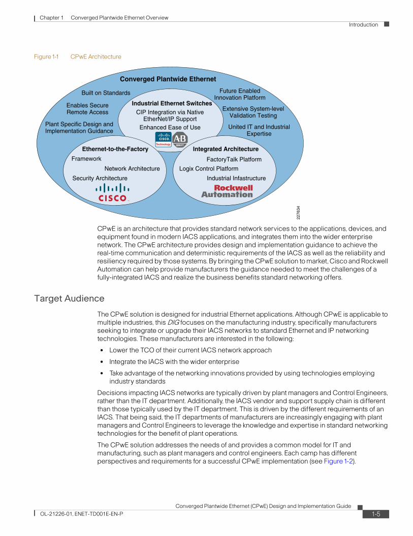
Figure1-1 depicts the key characteristics of CPwE. The inner circles represent the foundation of CPwE: EttF, the Rockwell Automation Integrated Architecture, and the line of industrial Ethernet switches developed with the best of Cisco and Rockwell Automation technologies. The outer circle represents the capabilities and benefits of CPwE such as unified IT and industrial expertise.
1-4Converged Plantwide Ethernet (CPwE) Design and Implementation Guide
OL-21226-01, ENET-TD001E-EN-P
Chapter 1 Converged Plantwide Ethernet Overview Introduction
Figure1-1 CPwE Architecture
CPwE is an architecture that provides standard network services to the applications, devices, and equipment found in modern IACS applications, and integrates them into the wider enterprise network. The CPwE architecture provides design and implementation guidance to achieve the real-time communication and deterministic requirements of the IACS as well as the reliability and resiliency required by those systems. By bringing the CPwE solution to market, Cisco and Rockwell Automation can help provide manufacturers the guidance needed to meet the challenges of a fully-integrated IACS and realize the business benefits standard networking offers.
Target Audience
The CPwE solution is designed for industrial Ethernet applications. Although CPwE is applicable to multiple industries, this DIG focuses on the manufacturing industry, specifically manufacturers seeking to integrate or upgrade their IACS networks to standard Ethernet and IP networking technologies. These manufacturers are interested in the following:
• Lower the TCO of their current IACS network approach
• Integrate the IACS with the wider enterprise
• Take advantage of the networking innovations provided by using technologies employing industry standards
Decisions impacting IACS networks are typically driven by plant managers and Control Engineers, rather than the IT department. Additionally, the IACS vendor and support supply chain is different than those typically used by the IT department. This is driven by the different requirements of an IACS. That being said, the IT departments of manufacturers are increasingly engaging with plant managers and Control Engineers to leverage the knowledge and expertise in standard networking technologies for the benefit of plant operations.
The CPwE solution addresses the needs of and provides a common model for IT and manufacturing, such as plant managers and control engineers. Each camp has different perspectives and requirements for a successful CPwE implementation (see Figure1-2).
Enables SecureRemote Access Extensive System-level
Validation Testing
Built on Standards Future EnabledInnovation Platform
Converged Plantwide Ethernet
Enhanced Ease of Use
Framework
Security Architecture
Network Architecture
FactoryTalk Platform
Industrial Infastructure
Logix Control Platform
CIP Integration via NativeEtherNet/IP Support
Industrial Ethernet Switches
Ethernet-to-the-Factory Integrated Architecture
Plant Specific Design andImplementation Guidance
United IT and IndustrialExpertise
2276
34
1-5Converged Plantwide Ethernet (CPwE) Design and Implementation Guide
OL-21226-01, ENET-TD001E-EN-P

Chapter 1 Converged Plantwide Ethernet Overview Introduction
Figure1-2 Business/Technical Decision Makers—IT versus IACS
For the IT department, it is critical to understand the various IACS requirements and operating environment. For the plant managers and control engineers, a deeper knowledge of the capabilities and functioning of standard networking technologies is required. The CPwE solution includes a large number of references to basic networking concepts to recognize the need to raise the level of knowledge and expertise of business and technical decision makers.
To increase its value and impact, the CPwE solution is developed and validated by Cisco and Rockwell Automation, leaders in their respective markets. The validated CPwE solution helps to increase success of manufacturers by more effectively addressing technical and business concerns of IT and Manufacturing organizations.
To summarize, the IACS and enterprise network convergence on which the CPwE solution is focused requires collaboration from both IT and manufacturing for successful implementation and operations. These organizations often have different objectives, ways of working and cultures that must be recognized. Each organization relies upon different partners, vendors and system integrators to implement and operate their solutions. IT may need its awareness levels raised concerning the differences and challenges posed by the manufacturing environment.
2276
35
CIO
IT Organization
Networking
IT Integrators
Software
BDM/TDM Vendors
Plant Information Level
AutomationSoftware/HardwareVendors
AutomationIntegrators
Original EquipmentManufacturers
Plant Manager
Advanced Manufacturing
Controls Engineer
Control Level
Device Level
Enterprise Level
Sensors I/ODrives
HMIController Historian
Plant Apps(MES, etc)
General PlantAccess
Plant LAN,WLAN
LAN/ WAN
Enterprise Apps(ERP, CRM, etc)
IP
Internet
• Customers• Suppliers• Partners
Office toPlant Gateway
Si
LWAPP
Robots
1-6Converged Plantwide Ethernet (CPwE) Design and Implementation Guide
OL-21226-01, ENET-TD001E-EN-P
Chapter 1 Converged Plantwide Ethernet Overview Introduction
Plant Managers and Control Engineers
As mentioned above, plant management and control engineer are the key owners of the IACS that the CPwE solution targets.
Plant managers are business owners for the plant and are responsible for achieving manufacturing targets by ensuring plant reliability, uptime, and energy efficiency. Their performance is often measured by plant profitability, throughput, quality, OEE and return on assets. Technology decisions are made related to reliability, risk-free operation, environment fit, and company-wide standards.
Control Engineers are technical owners of the plant and are responsible for the design, implementation and operations of the IACS that operate the manufacturing facility. They are responsible for the IACS equipment that supports the basic manufacturing process. They have a direct share of the responsibility of the quality and consistency of the end product, and often report to the plant management.
Key business drivers for plant managers and control engineers include the following:
• Reliability—The solution must support the operational availability of the manufacturing facility.
• Cost—Capital comes at a premium, and additional costs (or costlier components) must add clear value that is understood by the plant manager.
• Ease of integration—Not just with enterprise applications, but ease of integrating remote employer or partner expertise in a secure manner.
• Flexibility—The ability to rely on commercial off-the-shelf (COTS) equipment, provided by a number of vendors and supported from a common expertise.
Key concerns for plan managers and control engineers include the following:
• Performance—Ability of the network infrastructure to meet the real-time communications requirements of the IACS.
• Availability—Both the ability to limit the impact on operations of upgrading or maintaining the IACS, and the reliability of the supported base network infrastructure features to handle outages with minimal impact.
• Manageability—Ease of configuring, maintaining, and repairing the IACS.
• Compatibility—How the network infrastructure supports various types of IACS communications (see the “IACS Communication Protocols” section on page1-26) and the devices, controllers, human machine interfaces (HMIs), and applications already in use.
Both plant managers and control engineers typically rely on IACS vendors and partners with strong knowledge and track records in IACS. These vendors have varying degrees of capability and knowledge in deploying standard networking technologies and the relevant technical issues. Another objective of CPwE is to bring the relevant partners, such as system integrators and machine builders, up to speed on the availability and capabilities of industrial Ethernet and how to implement the technology in IACS environments.
CPwE enables the business drivers and addresses the key concerns relevant to plant managers, Control Engineers and the partner and vendor ecosystem that they rely upon for the IACS. The combination of Cisco and Rockwell Automation expertise, technologies, architectures, and validation work provides reliable reference architectures on which to base IACS network designs and implementations.
1-7Converged Plantwide Ethernet (CPwE) Design and Implementation Guide
OL-21226-01, ENET-TD001E-EN-P

Chapter 1 Converged Plantwide Ethernet Overview Introduction
Manufacturing IT
Although IT managers are typically the owners of the enterprise network infrastructure, they are not typically the owners of the IACS network infrastructure for many reasons. However, they are increasing getting involved with plant to business integration at the application layer, convergence of the IACS and enterprise networks, deploying, and operating common network technologies in plants. In the past, they were often seen by the plant managers and control engineers as an obstacle to be avoided, rather than a partner to be relied on for skills, expertise, and services. They usually made decisions to focus on standardized solutions, to reuse whenever possible, and to reduce cost. There was often a cultural gap between IT and the manufacturing world. However, because IT managers often have the deepest knowledge and expertise in standard networking technologies within the enterprise, their involvement is often required for a truly successful implementation of network convergence. To help overcome the cultural gap, the CPwE solution provides the following:
• Raises IT awareness of the particular challenges and requirements of IACS
• Outlines a solution and relevant design and implementation guidance that allows both plant and IT personnel to focus on a mutually-acceptable solution
• Develops a reference architecture standard on which to more quickly and assuredly deploy IACS networks
• Provides considerations for the use and deployment of common enterprise technology and tools whenever appropriate; for example, calling for standard IT external access technologies or applying standard network management tools and practices
• Addresses plant to enterprise network and application convergence, making it easier for IT to support wider business demands to be more aligned with manufacturing
• Pulls IT into the environment to deliver expertise and services based on their strength in standard Ethernet and IP networking technologies
Applications and Services Supported
The CPwE solution primarily supports IACS networks and their integration into the overall enterprise network. As noted earlier, IACS is a term that is meant to cover a large range of applications across multiple industries; Distributed Control Systems (DCS), Supervisory Control and Data Acquisition (SCADA), Programmable Automation and Logic Controllers (PACs and PLCs). There are other terms used for generally the same concept, for example Industrial Control System (ICS) is used in NIST and some ISA standards. IACS is used in ISA-99 Security standards. For the purpose of this DIG, Cisco and Rockwell Automation chose and standardized on IACS, but many other terms are used with similar meaning. IACS consists of the following:
• IACS devices, such as robots, sensors, actuator, and drives
• Human machine interfaces (HMIs) that provide visual status reports and control of the IACS
• Controllers such as programmable automation controllers (PACs) and the distributed control system (DCS)
• Higher-level plant systems, including the manufacturing execution system (MES) and historians
This version of the CPwE architecture focuses on the above items that support EtherNet/IP, which is driven by the Common Industrial Protocol (CIP) (see the “IACS Communication Protocols” section on page1-26) and in particular are tested with Rockwell Automation devices, controllers, and applications.
The key networking services that are supported in this version of the CPwE architecture include the following:
1-8Converged Plantwide Ethernet (CPwE) Design and Implementation Guide
OL-21226-01, ENET-TD001E-EN-P

Chapter 1 Converged Plantwide Ethernet Overview Introduction
• More alignment and focus on relevant aspects of deploying the IACS, for example the FactoryTalk™ integrated production and performance suite, the Logix multidiscipline Control Platform with RSLogix™ 5000™ and the IACS devices themselves
• Local area networking (typically defined as OSI Layers 1 and 2) to all the above items, including topology, port configuration, subnet and VLAN configuration, network protocols for resiliency and quality-of-service (QoS)
• Routing (typically defined as Layer 3) for all the above items, as well as to other areas of an enterprise network
• Design and implementation recommendations for network technical considerations such as topology, resiliency, and redundancy (including Multiple Spanning Tree Protocol and Flex Links), and management of multicast traffic when multicast is chosen over unicast for IACS network traffic delivery
• IP address allocation, assigning, and related services (for example, DHCP, BootP, and DNS)
• Basic network management from both the IT and plant floor personnel’s perspective, including the ease-of-use features available from the switch
• Network security for the IACS including Demilitarized Zone (DMZ), firewall, intrusion protection, endpoint security, and security monitoring, analysis, and response
• Secure remote access to the Cell/Area IACS network to improve service and support options and taking advantage of the interconnectivity that standard IT networking technologies allows.
These will be applied to network infrastructures with small (up to 50 Ethernet devices) to medium (up to 200 Ethernet devices) environments. Although larger environments will be addressed in future versions of this solution, the concepts and recommendations in this guide are envisioned to apply to those environments as well.
CPwE Solution BenefitsManufacturers can realize the following operational benefits of the CPwE solution:
• Enables and simplifies convergence of the IACS network with enterprise networks to improve the flow and integration of manufacturing information into business systems.
• Enables remote access for engineers, partners, and IACS equipment vendors for diagnostics and maintenance. Increases efficiency and response time and enables IACS vendors to provide services to manufacturers that may have limited subject-matter expert (SME) resources.
• Help reduce risk, increase plant uptime and improve Overall Equipment Effectiveness (OEE) through validated reference architectures with a focus on network resiliency and application availability.
• Help reduce operating and capital costs by using open standards to eliminate the need to support multiple protocols in IACS networks and to provide manufacturing companies more options when purchasing IACS equipment.
• Integrates more quickly advances in networking technology that come from working with standard technologies (for example, voice, video, and security).
The integration of advanced technologies by leading vendors such as Cisco and Rockwell Automation provide a unique value proposition relative to the rest of the industry by providing benefits beyond those associated with integration and use of open standards, including the following:
1-9Converged Plantwide Ethernet (CPwE) Design and Implementation Guide
OL-21226-01, ENET-TD001E-EN-P

Chapter 1 Converged Plantwide Ethernet Overview Introduction
• Combining two areas of expertise: the networking expertise of Cisco with the IACS and industrial networking expertise of Rockwell Automation.
• Providing architecture and terminology to support cultural and organizational convergence, as well as facilitate training and dialogue with IT and Control Engineers.
• Delivering end-to-end architecture with consistent technology, management tools, a common feature set, and software base making for stream-lined deployments and consistent management.
• Providing integrated security specifically configured for IACS networks to protect vital manufacturing assets, limit access to manufacturing equipment and help address issues such as patch management.
• Providing a foundation for deploying additional advanced technologies such as voice, video and wireless on the converged IACS network at the Cell/Area levels as the technology matures and the business requires.
• Simplifying deployment and helping to bridge the gap that often exists between IT and IACS networks by integrating and validating architectures with leading partners in the IACS market that ensure compliance with relevant industry standards.
The above capabilities depend on the deployment of technologies based on standard Ethernet and IP, and help demonstrate the value of open standards to differentiate Cisco and Rockwell Automation from vendors that have chosen to deploy solutions on the market that are not based on standard Ethernet and IP.
CPwE Solution FeaturesIACS network environments have evolved over the years, driven by a number of key design features. These features are not specific to industrial Ethernet, but to networking for the IACS in general. In the move towards industrial Ethernet, many of these design features still apply, although the importance sometimes shifts. For example, with standard Ethernet and IP technology industrial networks, security is a pressing issue, particularly if there is no restricted segmentation between the IACS and the larger business system. This section defines the following seven key features that manufacturers expect as best practices:
• Industrial characteristics
• Interconnectivity and interoperability
• Real-time communication, determinism, and performance
• Availability
• Security
• Manageability
• Scalability
This DIG provides details on why and how to deploy these features. The manufacturing industry, and especially plant managers, Control Engineers, and their partners and vendors, are looking for simple guidelines and recommendations. Each chapter in this DIG highlights key recommendations and steps to follow when designing and implementing industrial Ethernet for and IACS application.
1-10Converged Plantwide Ethernet (CPwE) Design and Implementation Guide
OL-21226-01, ENET-TD001E-EN-P

Chapter 1 Converged Plantwide Ethernet Overview Introduction
Industrial Characteristics
A key differentiator of the IACS from typical enterprise applications is the environment. The IACS end-devices and network infrastructure are located in harsh environments that require compliance to environmental specifications such as IEC529 (ingress protection) or National Electrical Manufacturers Association (NEMA) specifications. The IACS end-devices and network infrastructure may be located in physically disparate locations (up to miles away), and in non-controlled or even harsh conditions in terms of environmental considerations such as temperature, humidity, vibration, noise, explosiveness, or electronic interference.
The CPwE solution does not focus on environmental requirements and whether the IACS network infrastructure meets those requirements, outside of noting that this is an important consideration when choosing the network infrastructure. Additionally, the physical layer infrastructure is also driven by the physical requirements of the environment, with special consideration given to the potential for high noise. For physical layer considerations, refer to the ODVA's EtherNet/IP Media Planning Guide at the following URL:
http://www.odva.org/Portals/0/Library/Publications_Numbered/PUB00035R0_Infrastructure_Guide.pdf
This CPwE solution does focus on how the network infrastructure can support spatial challenges in an IACS network by supporting a number of topology options, thereby adapting to the industrial characteristics of the IACS.
The physical layout of the IACS equipment impacts the network topology for IACS networks. Unlike IT networks, which are largely redundant star topology networks, IACS networks have significant physical requirements that drive the use of topologies such as bus, linear, star and ring. In plants with long manufacturing lines, or equipment with long runs and interconnected operations (such as a printing press), it is often not feasible or cost-effective to use a redundant star topology. In manufacturing environments, the costs of cabling are significantly higher than typical office conditions to meet the harsh physical requirements. Given these cost considerations, many manufacturers choose to implement a ring topology rather than a redundant star topology where network resiliency is a requirement. In many cases, the IACS network utilizes a combination of topologies, with large rings connecting multiple star-based Cells/Areas.
Based on these considerations, the design guidelines provide information regarding the trade-offs between the various topologies to help manufacturers, system integrators and machine builders to make appropriate design decisions. Because of their significant use in manufacturing, bus topologies are discussed, as well as the associated trade-offs between linear, ring, and redundant star topologies (such as availability, and so on). Note that, although the linear topology is considered, Cisco and Rockwell Automation recommend ring or redundant star topologies for network infrastructure due to the resiliency they offer and therefore support higher availability and uptime.
For a summary of the advantages and disadvantages of each topology, see “Cell/Area Topology Comparison” section on page 3-27.
Figure1-3 shows a redundant star topology.
Note Figure1-3 to Figure1-5 are meant to depict the network device topology and not necessarily the number or type of end-devices.
1-11Converged Plantwide Ethernet (CPwE) Design and Implementation Guide
OL-21226-01, ENET-TD001E-EN-P

Chapter 1 Converged Plantwide Ethernet Overview Introduction
Figure1-3 Redundant Star Topology
Figure1-4 shows a ring topology.
Figure1-4 Ring Topology
Figure1-5 shows a bus topology.
Layer 2Switch
2276
36
Cell/Area Zone
Stacked Layer 3 Switches
ProgrammableAutomation
Controller (PAC)
DistributedI/O (DIO)
Human MachineInterface
(HMI)
22
76
37
Cell/Area Zone
Stacked Layer 3 Switches
Layer 2 Switch
ProgrammableAutomation
Controller (PAC)
HumanMachineInterface
(HMI)
DistributedI/O (DIO)
1-12Converged Plantwide Ethernet (CPwE) Design and Implementation Guide
OL-21226-01, ENET-TD001E-EN-P

Chapter 1 Converged Plantwide Ethernet Overview Introduction
Figure1-5 Bus Topology
The CPwE solution design and implementation guidelines include the following key considerations:
• Choosing a topology that meets the performance, cost, and spatial requirements of the IACS application.
• The layout of plant operations, conduit/wiring paths, cost, and desired level of availability determine whether the network topology follows a tree, ring, star, linear, trunk and drop topology, or a hybrid.
• Use ruggedized/hardened network devices in the plant environment where needed, but consider using non-industrial routers, switches, and firewalls where appropriate to reduce cost.
• The number of IACS devices and grace ports for programming/troubleshooting and 10 percent spare for future expansion determines the type and size of switch needed at various levels.
• Hierarchically-layered switches may be required to address density, distance, or communication path challenges.
Interconnectivity and Interoperability
The ability to interconnect and interoperate a wide range of IACS network devices and applications through a common, standard network infrastructure is a key goal for IACS networks. The interconnectivity and interoperability feature also applies to network infrastructure devices themselves. Standard Ethernet and IP network technologies offer the best opportunity to do such as the barriers for IACS vendors to integrate this into their product is low and the concepts and technology are widely available. This CPwE solution will focus on the use of standard Ethernet and IP networking technologies to deliver maximum interconnectivity and interoperability. Interconnectivity suggests that the IACS network devices can communicate using standard protocols at Layers 2, 3, and 4 (Ethernet, IP and TCP/UDP). Interoperability suggests that the IACS network devices can interoperate using standard, common protocols at Layer 7 (application). IACS
2276
38
Cell/Area Zone
Stacked Layer 3 Switches
Layer 2 SwitchHuman
MachineInterface
(HMI)
VariableFrequencyDrive (VFD)
ProgrammableAutomation
Controller (PAC)
1-13Converged Plantwide Ethernet (CPwE) Design and Implementation Guide
OL-21226-01, ENET-TD001E-EN-P

Chapter 1 Converged Plantwide Ethernet Overview Introduction
network devices with different application layer protocols may not interoperate without some gateway device/service to perform an application layer translation. This CPwE solution is based upon the use of CIP as the common application layer protocol for IACS network interoperability employing EtherNet/IP as the IACS network.
The TCP/IP protocol suite with the CIP application layer protocol helps ensure that IACS devices from a variety of vendors will communicate and work together. Additionally, conformance testing from such organizations such as the ODVA certifies that EtherNet/IP devices from various vendors communicate and interoperate. The TCP/IP standards outline a wide range of features and functions. This solution will identify key features and functions from the TCP/IP suite and describe how they can be implemented with the products from Cisco and Rockwell Automation. Therefore, in theory, the concepts, recommendations and implementations CPwE specifies should be applicable in a wide range of other vendor's devices and solutions.
The key TCP/IP protocols relevant to this solution are described in Table1-1. The 7-layer OSI model is used to segment the various protocols and standards.
Chapter 3, “CPwE Solution Design—Cell/Area Zone” and Chapter 4, “CPwE Solution Design—Manufacturing and Demilitarized Zones” of this DIG describes how and why these protocols and standards are applied. Note that there are a range of other protocols involved in standard networking that are not mentioned here as they are either not relevant or are transparent functions of the IACS network infrastructure and end-devices. For more information on a complete set of standard networking features and functions, see Cisco's technology support library at the following URL:
http://www.cisco.com/cisco/psn/web/psa/design.html?mode=tech
By definition, industrial Ethernet (IE) networks should operate on standard Ethernet and IP networking technologies and infrastructure, although some industrial Ethernet networks, not considered within this DIG, incorporate proprietary technologies so that common infrastructure may not be used. However, standard networking technologies have a wide range of service and configuration options that need to be considered to effectively support the IACS application. As well, various industrial Ethernet protocols specify various networking features that then must be available to operate at required performance levels, not all of which are based upon openly available standards. The “IACS Communication Protocols” section on page1-26 lists the relevant general industrial protocols and the corresponding industrial Ethernet versions. This solution architecture focuses on CIP, the application layer protocol for EtherNet/IP. Other network protocols are referenced (see the subsections on traffic flows in the “Cell/Area Zone” section on page 2-3 and “Manufacturing Zone” section on page 2-5).
Table1-1 Key TCP/IP Protocols
Layer Name Function Key Protocol
4 Transport Reliable network communication between end nodes,
TCP, UDP
3 Network Path determination, routing Internet Protocol v4 (IPv4), Internet Group Management Protocol (IGMP), DSCP, Internet Protocol Security (IPsec), OSPF
2 Data Link Physical addressing, network topology, line discipline, error notification, ordered delivery of frames, and flow control
MAC, Ethernet (IEEE802.3), Spanning Tree Protocol, Virtual Local Area Networks (VLAN), Link Aggregation Control Protocol (LACP)
1 Physical Media, signal and transmission protocol
Ethernet (IEEE 802.3) including 10, 100 Mb and Gigabit Ethernet in copper and fiber varieties
1-14Converged Plantwide Ethernet (CPwE) Design and Implementation Guide
OL-21226-01, ENET-TD001E-EN-P

Chapter 1 Converged Plantwide Ethernet Overview Introduction
A key objective of the CPwE architecture is to interconnect standard EtherNet/IP IACS network devices and maintain interoperability with standard Ethernet and IP network technology infrastructure. This CPwE solution uses systems and infrastructure from Cisco and Rockwell Automation, but this solution could be applied using applications and infrastructure from other vendors.
Real-Time Communication, Determinism, and Performance
IACS networks differ significantly from their IT counterparts in their need to support real-time communications, which means communicating messages with minimal latency (time delay between message sent and message received) and jitter (the variance of the latency), significantly lower than typical Enterprise applications. Real-time communications help the IACS become more deterministic. Although the network plays a role in the deterministic nature of a system, a number of other factors, such as end-device latency and response time, are also involved. But the network has an important role, not just by sending packets quickly and consistently, but in the services it offers and supports, such as quality-of-service (QoS) and precision time. The capabilities of standard Ethernet and IP networks to support challenging real-time communications are described in this DIG.
IACS networks have different real-time communications requirements based on the type of application. Figure1-6 represents examples of application requirements as developed by ARC Research in 2006. This is representative only. Figure1-6 does not represent the testing and characterization results of the CPwE solution.
Figure1-6 Real-Time Applications (Source: ARC Research, 2006)
2279
43
ProcessAutomation
Function
CommsTechnology
Period
Industries
Applications
Information Integration,Slower Process Automation
.Net, DCOM, TCP/IP
1 second or longer
Oil and gas, chem, energy, water
Pumps, compressors, mixers
Monitoring of temp, press, flow
Factory Automation
Standard Ethernet+ RT Application Protocol
10 ms to 100 ms
Auto, food and bev, elect. assembly,semiconductor, metals, pharma
Material handling, filling,labeling, palletizing, packaging
Welding, stamping, cutting,metal forming, soldering, sorting
Motion Control
Hardware/softwaresolution
<1 ms
Subset of factory automation
Synchronization of mult. axes:printing presses, wire drawing,
web making, picking and placing
FactoryAutomation
MotionControl
1-15Converged Plantwide Ethernet (CPwE) Design and Implementation Guide
OL-21226-01, ENET-TD001E-EN-P

Chapter 1 Converged Plantwide Ethernet Overview Introduction
The CPwE solution provides design and implementation guidance to help achieve the real-time communications requirements of an IACS. Key considerations in achieving real-time communications include the following:
• Number of switches, routers, and amount of traffic in the Layer 2 network, all of which affects latency and jitter.
• Ratio of LAN switch ports to uplink switch ports based on traffic loads and patterns. Typically, this means using 10/100 Mbps for IACS devices and 10/100/1000 Mbps for uplinks.
• Use of Internet Group Management Protocol (IGMP) to manage the efficient delivery of multicast traffic.
• Use of quality-of-service (QoS) parameters to meet the real-time requirements of various traffic flows.
Availability
Availability of the IACS has a direct correlation to the plant uptime and OEE of a manufacturing facility. Because the network is a key aspect of the overall system, these requirements translate directly to the IACS network. This CPwE solution outlines a number of features that not only maintain IACS network availability in the case of link-loss, device failure and other outages, but once an outage occurs, features that enable quick restoration of IACS network services to re-start manufacturing as quickly as possible. CPwE outlines a number of IACS network traffic or application types and what requirements they have for network resiliency. These network capabilities were then tested to validate that those requirements were met, with documented results and best practices to help determine what options are available for a variety of IACS application types.
Note that limitations in the network technology may also limit the application of high availability features. For example, the lack of the ability of the network to converge quick enough and the cost associated with redundant wiring have often led to non-redundant topologies being implemented in IACS networking environments. The CPwE solution outlines the capabilities so as to let manufacturers, system integrators and machine builders make decisions on the level of network availability needed for the overall system.
High availability considerations are identified in each aspect of the CPwE solution. Key considerations include the following:
• Creating alternative data communication paths, regardless of physical layout. Risk profile, opportunity cost, culture, and other variables determine how much and to what level redundant paths are required.
• Eliminating single points of failure with critical operations, including such items as dual-power supplies, alternate routes for redundant media, redundant IACS network infrastructure, such as routers, switches, and firewalls.
• Using advanced network resiliency and convergence techniques to improve availability, such as EtherChannel/LACP, Multiple Spanning Tree Protocol (MSTP), Flex Links, and Hot Standby Routing Protocol (HSRP).
• Although redundant star topology offers the best convergence capabilities, consider alternative ring recovery techniques when configured in a ring topology.
• Using routing protocols such as EIGRP or OSPF to achieve high availability.
• Integration of the network device into the IACS application to better identify and diagnose issues when they do occur.
• Features and services to allow the quick replacement of failed devices with minimal or no configuration of the replacement device.
1-16Converged Plantwide Ethernet (CPwE) Design and Implementation Guide
OL-21226-01, ENET-TD001E-EN-P
Chapter 1 Converged Plantwide Ethernet Overview Introduction
Security
IP networking facilitates interconnection of the IACS network with the enterprise network. Many industries have implemented enterprise applications for more efficient manufacturing, as well as Internet business applications to communicate more efficiently with their suppliers, customers, and business partners. Internet-based enterprise resource planning (ERP) and supply chain management (SCM) systems simplify connections both to other organizations and to internal business processes. These connections can enable greater efficiencies in processes and manufacturing. In large manufacturing or utility operations, small percentage increases in efficiency can translate into significant cost savings.
However, connecting the IACS network to the enterprise network exposes the security risks of the Internet and enterprise network to the IACS application. Mitigating these risks may be more difficult and more critical than in the enterprise network because of the higher requirement for availability in an IACS and the sensitivity of these systems to different disruptions. Of the three security properties of confidentiality, integrity, and availability, IACS applications are primarily concerned with availability and integrity. Many of the applications that IACS networks support cannot be stopped or interrupted without serious physical damage or loss of productivity with measurable financial damage. On the other hand, confidentiality and integrity are the primary design considerations for enterprise networks. For example, it is preferable for an ecommerce server to be temporarily unavailable rather than for it to lose transactions or divulge credit card numbers. Consequently, the network architectures, firewall configurations, intrusion detection configurations, and other aspects of a security deployment require tuning and customization to properly support IACS applications. Building secure and reliable IACS networks utilizing Ethernet and IP has been a challenge.
Standards bodies such as ISA-99 and NIST are continually developing security design axioms, and there is an emerging consensus on what a secure IACS architecture should provide. This includes an IACS network that is highly available and redundant, has fast convergence, thus being more deterministic and therefore more suitable for real-time control, and is secure against both outside and inside threats. The specific security principles of the CPwE architecture are as follows:
• Control data flows between different IACS levels (ACLs, firewall rules, etc).
• Prevent direct communication between IACS and enterprise applications.
• Restrict real-time manufacturing data to the IACS network.
• Restrict enterprise access to the mirror version or copies of IACS data to the DMZ.
• Authenticate and authorize user access based on the level within the IACS network and the role (read/read-write/local/remote/vendor/partner).
• Control rogue access to switches inside the IACS network (port level MAC-address controls, administratively shutdown unused ports, etc).
• Control which IACS devices can be plugged into the switch (for example, port security, DHCP snooping).
• Detect and mitigate malicious traffic originating from infected devices that are plugged into the IACS network.
• Detect and mitigate malicious traffic originating from the corporate IT network.
• Secure connectivity for remote access to IACS devices.
• Use DMZ design options based on costs and levels of security and redundancy required.
• Limit rogue network communication activity from impacting networking devices (set root bridge, SNMP capabilities, and so on).
1-17Converged Plantwide Ethernet (CPwE) Design and Implementation Guide
OL-21226-01, ENET-TD001E-EN-P

Chapter 1 Converged Plantwide Ethernet Overview Introduction
• Regarding data and services in the DMZ, connection initiation should originate from either the Manufacturing or Enterprise zone and terminate in the DMZ. Connections originating from the DMZ should be exceptions.
• Document and define policy and risk appropriate for the environment.
The above are provided as principles, with the understanding that customers may choose to make exceptions.
This CPwE solution will incorporate these security best practices into the design and implementation guidance for IACS networks. A security risk assessment is recommended to determine the appropriate level of risk mitigation required for a specific situation. The CPwE solution incorporates design and implementation guidance to help secure remote access to the Cell/Area IACS network.
Manageability
Manageability is a key consideration for an IACS network. Individuals with a basic level of networking skills should be able to manage and monitor the network. On the other hand and with more regular occurrence, IT professionals are getting involved with maintaining and support IACS networks. The IACS networking solution needs to accommodate manageability via existing tools and procedures by plant personnel without deep networking expertise as well as manageability via enterprise-level network management tools and procedures by IT network experts.
Key manageability concerns include the following:
• Configuration of switches using IT tools such as the command-line interface (CLI) and IACS tools such as RSLogix™ 5000 and Device Manager.
• Single switch management utilizing a single GUI such as RSLogix 5000 and Device Manager, multiple switch management utilizing a single GUI such as Cisco Network Assistant.
• Leveraging existing SNMP-based management systems when and where they make sense.
• Using other network devices such as routers and security appliances with similar configuration functionality.
• Using Smartport templates for easy port configuration based on application types.
• Assigning consistent IP addresses to devices. IP addresses are often coded into the logic of various IACS devices, rather than using dynamic IP address services such as Dynamic Host Configuration Protocol (DHCP).
• Considering various easy replacement options for network infrastructure elements.
• Using systems that offer notification of critical network events (for example, if an Ethernet link goes up or down), and the means to diagnose and debug problems within the network infrastructure.
• Staging software upgrades for network devices.
• Allowing for patch management of Windows-based IACS servers and clients.
• Standardizing hardware and software elements wherever possible.
• Driving the integration of basic network administration into the existing applications based on various IACS network protocols.
1-18Converged Plantwide Ethernet (CPwE) Design and Implementation Guide
OL-21226-01, ENET-TD001E-EN-P

Chapter 1 Converged Plantwide Ethernet Overview Introduction
Scalability
An IACS may come in a wide range of sizes, from small machine builder solutions to the extremely large plant complexes (for example, an automotive plant). The IACS may include only a small number of network infrastructure devices (up to 50) to multiple 10,000s. The IACS solution architecture concepts and recommendations need to be applicable to that range, noting the considerations for various sizes.
This version of the CPwE solution architecture focuses on basic concepts, tested in typical small-to-medium network installations. Rather than focusing on full-range and scalability testing, this solution architecture focused on defining and testing core concepts that are applicable to a full range of IACS sizes. Specific considerations for extremely small, pre-built systems (such as machine builders) or large to extra large implementations were left for future versions of the CPwE solution architecture. The basic concepts in this guide are applicable to the range of IACS.
Key scalability considerations include the following:
• Cost
• Network infrastructure sizing and performance constraints
• Network infrastructure tiering to meet spatial, size, and performance criteria
• Link aggregation to achieve higher bandwidth requirement
• IP addressing schema and allocation mechanism
• Maintenance and management considerations as manual tasks have greater impact in large environments
Scope of the CPwE SolutionThis phase of the CPwE introduces basic network architectures based on standard technologies to provide services to an IACS through design and implementation guidance to implement an IACS network.
Key aspects of this phase of the CPwE solution include the following:
• Wired solutions for the IACS.
• The CPwE logical framework and solution are applicable for small to large IACS environments, but the testing and specific design recommendations were made based on small (less than 50) to medium (less than 200) network infrastructure devices.
• Key technical considerations such as the following:
– Topology
– Real-time communications
– Networking functions of the OSI Layers 2 and 3 configuration including basic routing protocols
– Insulation and segmentation including VLANs and DMZ design
– Multicast traffic handling, including IGMP
– Quality-of-service (QoS)
– Redundancy and resiliency (including application of the standard MSTP EtherChannel/LACP, and Flex Links)
1-19Converged Plantwide Ethernet (CPwE) Design and Implementation Guide
OL-21226-01, ENET-TD001E-EN-P

Chapter 1 Converged Plantwide Ethernet Overview Introduction
– IP address allocation, assignment, and related services (for example, DHCP and DNS) in a manufacturing perspective
– Basic network management
– Network security for the IACS, including DMZ, firewall, intrusion protection, endpoint security, and security monitoring, analysis, and response
• Design and implementation is based on EtherNet/IP (driven by CIP application layer)
Phase 1—Ethernet-to-the-Factory (EttF)
Phase 1 (Versions 1.0 - 1.2) of EttF was the initial jointly developed IACS network architecture by Cisco and Rockwell Automation. The solution was mainly focused on network considerations and recommendations, albeit to support IACS applications. Phase 1 introduced the Six-Level logical Plant Architecture as the Reference Model for the solution. Phase 1 features of the solution, including:
• Key solution features (for example, real-time communication, availability, security) and described how they are supported by various aspects of the solution.
• Design and implementation guidance for key zones of the IACS network: Cell/Area, Manufacturing, and DMZ including the key network functions required.
• Test description and results to support recommendations and to be used as guidance for estimating performance of key network characteristics such as high availability and resiliency.
Phase 2—Converged Plantwide Ethernet (CPwE)
Phase 2, CPwE, builds upon and extends the Phase 1 EttF solution. CPwE represents further integration of the standard Ethernet and IP network infrastructure with the IACS applications as well as the convergence of IACS and enterprise networks. CPwE uses the same key structures and features as EttF, with modifications and additions. The CPwE solution will continue to focus on IACS applications using EtherNet/IP. The key areas of addition and extension include the following:
• Enhanced industrial Ethernet switching infrastructure. Replace the Cisco 2955 industrial switch with the Rockwell Automation Stratix 8000™ and highlight key new features including:
– Additional configuration options, for example 6 to 26 port configurations with a mix of both fiber and copper ports.
– Ease-of-use features such as pre-defined Smartports for easy setup and configuration and removable Compact Flash memory for easy switch replacement.
• Enhanced Cell/Area zone design options and detailed resiliency testing for both ring and redundant star topologies to support a variety of IACS applications including support for CIP Implicit I/O and CIP Explicit informational messaging.
• Design and implementation of secure remote access to Cell/Area IACS networks.
• Integrate the Rockwell Automation FactoryTalk production and performance suite into the solution design.
• Integration of the industrial Ethernet switches into the IACS application (e.g., FactoryTalk, RSLinx Data Servers and Logix control platform applications) via EtherNet/IP protocol support for enhanced manageability.
1-20Converged Plantwide Ethernet (CPwE) Design and Implementation Guide
OL-21226-01, ENET-TD001E-EN-P
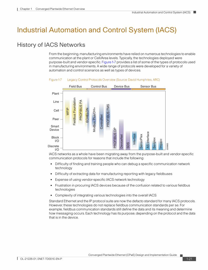
Chapter 1 Converged Plantwide Ethernet Overview Industrial Automation and Control System (IACS)
Industrial Automation and Control System (IACS)
History of IACS NetworksFrom the beginning, manufacturing environments have relied on numerous technologies to enable communication at the plant or Cell/Area levels. Typically, the technologies deployed were purpose-built and vendor-specific. Figure1-7 provides a list of some of the types of protocols used in manufacturing environments. A wide range of protocols were developed for a variety of automation and control scenarios as well as types of devices.
Figure1-7 Legacy Control Protocols Overview (Source: David Humphries, ARC)
IACS networks as a whole have been migrating away from the purpose-built and vendor-specific communication protocols for reasons that include the following:
• Difficulty of finding and training people who can debug a specific communication network technology
• Difficulty of extracting data for manufacturing reporting with legacy fieldbuses
• Expense of using vendor-specific IACS network technology
• Frustration in procuring IACS devices because of the confusion related to various fieldbus technologies
• Complexity of integrating various technologies into the overall IACS
Standard Ethernet and the IP protocol suite are now the defacto standard for many IACS protocols. However, these technologies do not replace fieldbus communication standards per se. For example, fieldbus communication standards still define the data and its meaning and determine how messaging occurs. Each technology has its purpose, depending on the protocol and the data that is in the device.
2208
83
Field Bus
WF
IP
Fie
ldbu
s F
ound
atio
n
PR
OF
IBU
S P
A
PR
OF
IBU
S F
MS
PR
OF
IBU
S D
P
Dev
iceN
et
SD
S Inte
rbus
Sen
soP
lex
AS
-inte
rfac
e
Ser
iple
x
Impa
cc
EC
HE
LON
Mod
bus
Plu
s/D
H+
Con
trol
Net
Plant
Line
Cell
Peer
SmartDevice
BlockI/O
DiscreteI/O
Control Bus Device Bus Sensor Bus
1-21Converged Plantwide Ethernet (CPwE) Design and Implementation Guide
OL-21226-01, ENET-TD001E-EN-P

Chapter 1 Converged Plantwide Ethernet Overview Industrial Automation and Control System (IACS)
IACS Components
Physical Layer
Many of the purpose-built and vendor-specific industrial technologies have specific physical media requirements that often require unique cabling (such as co-axial) and specialized termination (such as serial connectors). These various physical layer specifications dictate a complete physical media upgrade when migrating from one network to another. In comparison, industrial Ethernet uses standard Ethernet wiring; either twisted pair cables, or multimode or single mode fiber. The connectors for these various types of Ethernet wiring are also standardized with RJ45 connectors for copper cables, and SC/ST or LC connectors for fiber optic cables. Sealed connectors such as M12 are required for IP67 applications. The benefit of industrial Ethernet, once physically installed, is connectivity of IACS devices from multiple IACS vendors.
Cisco and Rockwell Automation recommend readers review the ODVA's EtherNet/IP Media Planning Guide (http://www.odva.org/Portals/0/Library/Publications_Numbered/PUB00035R0_Infrastructure_Guide.pdf).
Typical Ethernet speeds are 10Mbps, 100Mbps, and 1Gbps. 10 Gbps is mainly being deployed in enterprise-wide backbone networks. IACS installations rely upon 10Mbps or 100Mbps Ethernet for IACS devices while Gigabit Ethernet is appearing in industrial Ethernet backbones.
The physical layout and communication requirements of a manufacturing environment dictate how various standard Ethernet resources are physically connected. Typical Ethernet environments have full-duplex connection via a redundant star topology. Other options are possible such as ring, trunk and drop, and linear. Specific operating constraints when using Ethernet in these other models are discussed in Chapter 3, “CPwE Solution Design—Cell/Area Zone.”
Networking Equipment
Note As IACS networks adopt standard Ethernet and IP technologies, they benefits from the access to a wide range of standard networking equipment. The type of device required depends on many factors, the first being what layer communication protocol is in use. For example, Layer 3 refers to the Network layer of the OSI model, and in standard networking refers to the IP protocol.
Figure1-8 shows, various types of devices working at different layers of the OSI model and common devices that perform representative interconnect functions.
Figure1-8 Open System Interconnection (OSI) Reference Model l
Application
Presentation
Session
Transport
Network
Data Link
Physical
Application
Presentation
Session
Transport
Network
Data Link
Physical
Gateway
Router
Bridge
Repeater
2208
84
1-22Converged Plantwide Ethernet (CPwE) Design and Implementation Guide
OL-21226-01, ENET-TD001E-EN-P

Chapter 1 Converged Plantwide Ethernet Overview Industrial Automation and Control System (IACS)
Many early IACS Ethernet networks used simple, inexpensive repeaters (also known as hubs) to connect IACS devices together. In many cases, these were the same Ethernet hubs that were handling front-office workstations. As a multi-port broadcast device, a hub does the following:
“Creates one big collision domain, with all traffic shared. As more network nodes are added or traffic increases, every node in the collision domain has a greater chance of slowing communication or having a collision. Additionally, because IACS networks are not configured to differentiate between the relative importance of Ethernet packets, it is possible for non-essential traffic on the network (perhaps people backing up their computers to the network server or printing a large document across the network) to slow or collide with essential traffic (such as inter-controller communication or HMI polling).”
(Source:http://www.cisco.com/warp/public/779/smbiz/languide/p4.html)
The next advancement in IACS industrial Ethernet network design was the use of switches; a type of multi-port Layer-2 bridge. Switches can segment networks into virtual LANs (VLANs) to separate collision domains. Ethernet switches also typically have a fast internal backbone, which helps eliminate collisions among data packets. Collisions are eliminated for IACS network devices directly connected to switches in full-duplex mode. This occurs because full-duplex Ethernet devices can both send and receive packets of Ethernet data at the same time. This increases the level of determinism of Ethernet, assuring that packets arrive with much greater certainty, and that each port has more bandwidth available for communication at any time.
Adding some intelligence to the switch improves traffic management and prioritization capabilities, meaning that the switch can provide more granular quality-of-service (QoS) for IACS networks. One example is the management of multicast traffic. Management of the multicast (rather than treating it as broadcasts as unmanaged switches do) significantly reduces the number of messages that end-devices and IACS network infrastructure must process, leading to better network and device performance. As another example, by assigning a priority to time-sensitive data, managed Ethernet switches can prioritize that traffic above lower-priority data. This ensures that high-priority IACS traffic always traverses the network, even if the network becomes congested. Switches can also classify, reclassify, police, mark, and even drop incoming data packets as application priorities require. The use of managed versus unmanaged switches is a key consideration facing those implementing IACS networks today. Both Cisco and Rockwell Automation highly recommend the use of managed switches. For further details on managed versus unmanaged switches, see the “Topology Options and Media Considerations” section on page 3-21.
In some cases, Layer-3 switches or routers are used in manufacturing environments. Layer-3 switches or routers forward information between different VLANs or subnets. They use information in the IP header (Layer 3) to do so. Regardless of the specific layer being connected, switches provide IACS networks with many of the safeguards that were realized by the natural separation inherent in existing IACS-optimized networks.
The specifics of how a Layer-2 switch is used compared to a Layer-3 switch, how to implement multicast management, and how QoS can be implemented are addressed in the “Cell/Area Zone” section on page 2-3.
IACS Network Devices
Many types of devices are used in IACS applications. Some are small, simple, single-function sensors or input/output devices (e.g., a light or on-off switch), while others are feature-rich, programmable automation controllers (PACs). The breadth and depth of available devices is driven primarily by IACS vendors and their partners and suppliers. Figure1-9 shows some of the various types of devices connected to an IACS network.
1-23Converged Plantwide Ethernet (CPwE) Design and Implementation Guide
OL-21226-01, ENET-TD001E-EN-P

Chapter 1 Converged Plantwide Ethernet Overview Industrial Automation and Control System (IACS)
Figure1-9 Industrial Network Devices
Table1-2 identifies the IACS and network infrastructure devices used within the architecture diagrams contained throughout this DIG, such as Figure1-5.
2276
39
Human MachineInterface (HMI)
ProgrammableAutomation
Controller (PAC)Programmable
LogicController (PLC)
Industrial PC
Power MonitorPC Controller
ServoDrive
SafetyController
VariableFrequency
Drive(VFD)
Actuator
Sensor
SafetyDIO
DistributedInput/Output
(DIO)DCS
Table1-2 IACS Network Components
Device Icon Description Product/Platform
Layer 2 Industrial Ethernet access switch
Allen-Bradley Stratix 8000 or Cisco IE 3000 Industrial Ethernet switch in a variety of port configurations
Catalyst 2960 switch for non-industrial, rack mount environments, in a variety of port configurations
Multilayer distribution switch Catalyst 3750G in a variety of port configurations
Router/Switch Catalyst 4500 or 6500 in a variety of configurations
Firewall Adaptive Security Appliance (ASA) 5500 series
Programmable Automation Controller (PAC)
Allen-Bradley ControlLogix System
Safety Programmable Controller Allen-Bradley GuardLogix System
1-24Converged Plantwide Ethernet (CPwE) Design and Implementation Guide
OL-21226-01, ENET-TD001E-EN-P

Chapter 1 Converged Plantwide Ethernet Overview Industrial Automation and Control System (IACS)
Older lower-level IACS network devices tend to use specific IACS network protocols and are capable of only low data rates and volumes, albeit with deterministic characteristics. More advanced IACS devices have internal logic optimized for I/O control with the ability to support higher data rates and volumes. Many of these newer IACS network devices now come standard with more communication options including standard Ethernet and IP.
The trend with IACS network devices is to add more functionality and capabilities at all levels. This is occurring because of the continual evolution in the microelectronics industry and access to lower cost components with more functionality. The low cost of microcontrollers is already making it easy for design engineers to include Ethernet and IP in a growing number of products that exist in common IACS applications. As with many electronic technologies, after a few high-end products incorporate a feature or function, it rapidly becomes a common attribute on many of the emerging new products. Regardless, there is and will continue to be a place for simple, low cost, and lower capability devices in IACS applications. When Ethernet and IP represents too much of a cost and capability increase for the end-device itself, these devices will continue to communicate via simple, non-Ethernet I/O networks; for example, a distributed I/O device used as an Ethernet network concentrator connecting a number of simple devices, such as a push button, to a controller.
Industrial Computing
Computing technology has been used for years in purpose-built and vendor-specific manufacturing environments. Just as with IT, the technology has migrated from mainframes and mini-computers with dumb terminals to standalone, dedicated computing platforms. With the cost of computing highly commoditized, the trend now is to put computing power anywhere in the IACS network using high performance CPUs. By using fanless and diskless PCs with features such as touchscreens, class 1 division 2 environment certification, and mission-critical solid-state drives, computing platforms are now suitable for any harsh industrial or embedded device application.
Programmable Automation Controller (PAC)
Allen-Bradley CompactLogix System
Programmable Automation Controller (PAC)
Allen-Bradley CompactLogix System
Variable Frequency Drive (VFD) Allen-Bradley PowerFlex Drive
Human Machine Interface (HMI) Allen-Bradley PanelView Plus
Distributed Input/Output (DIO) Allen-Bradley POINT I/O
Safety Distributed Input/Output (DIO)
Allen-Bradley CompactBlock Guard I/O
Table1-2 IACS Network Components (continued)
Device Icon Description Product/Platform
1-25Converged Plantwide Ethernet (CPwE) Design and Implementation Guide
OL-21226-01, ENET-TD001E-EN-P

Chapter 1 Converged Plantwide Ethernet Overview Industrial Automation and Control System (IACS)
From an operating system perspective, IACS vendors have moved away from legacy or custom-built operating systems to common off-the-shelf operating systems based on Microsoft or Unix derivatives (including Linux) for many products. The benefit of this development is a simpler and faster application configuration environment both for vendors as well as manufacturers. This migration has coincided with the overall general trend in the software industry towards Internet browser-based technology. This offers IACS vendors the ability to embed web interfaces directly into IACS network devices.
The downside of all these developments is a significant amount of system complexity related to security and patch management. The specific application requirement of the IACS is discussed in Chapter 2, “Converged Plantwide Ethernet Solution.”
IACS Communication Protocols
Communication Model
The communication messaging model in IACS environments has only loose ties to traditional client-server or peer-to-peer IT models. Unlike the typical IT environment, standard Ethernet and IP IACS network communications have different patterns, loads, and frequencies required by the manufacturing process they support. Standard IACS network communications are also driven by status polling between devices, cyclic data transfer, or change of state message patterns. The different requirements of the layers previously discussed have led key IACS providers to define a variety of communication models, including OSI Layers 1 to 7 networking protocols.
These communication models have both strong commonalities and differences. In common, they differentiate the control or I/O traffic between devices and the controllers (Levels 0-1) and information traffic within the upper level applications down to the controller (Level 1). This differentiation is made to meet the stringent requirements at these lower levels (see the “Industrial Automation and Control System Reference Model” section on page 2-1). However, the models can differ greatly at the Cell/Area levels. One example is the producer-consumer model applied in the ODVA Common Industrial Protocol (CIP). This model describes how devices “produce” data to be “consumed” by other devices; in particular, the controllers that take action on their data and control their behavior. These models are incorporated into the IACS protocols described below. They are important because they impact or shape the network traffic that is produced by the applications that use them.
CIP, for example, defines two distinct message types: Explicit-informational messages and Implicit I/O messages. In an Explicit message, the action is explicitly defined in the message; for example, read the value of a variable. Explicit messaging is a request/response, client/server-like protocol typically used for “information” and administrative messaging and is implemented over the Layer 4 TCP protocol. Explicit messages are information messages used for additional device configuration and acquisition of device diagnostics. Explicit messages are highly variable in both size and frequency based on configuration and application.
Implicit I/O messages are typically used for cyclic, input/output messages to/from controllers and devices. In Implicit I/O messages, the data is implied; the communicating parties inherently know how to parse the message content because of contextual knowledge. Implicit I/O messaging or real-time IACS messages are sent at requested packet intervals (RPI), and although the size can vary, it is consistent after the configuration is set and is generally smaller than Explicit messages. Implicit I/O messages contain IACS control data that must be interpreted very quickly by the receiving device, which demands network and end-device performance that is different than other traffic. With Implicit I/O traffic, the UDP protocol is used (either unicast or multicast) to minimize processing resources and time on the end-device.
1-26Converged Plantwide Ethernet (CPwE) Design and Implementation Guide
OL-21226-01, ENET-TD001E-EN-P

Chapter 1 Converged Plantwide Ethernet Overview Industrial Automation and Control System (IACS)
Network traffic in IACS environments can include significant and varying amounts of unicast, multicast, or broadcast traffic driven by the communication models applied (e.g., producer/consumer, client/server, master/slave, multi-master, or peer-to-peer relationships). For the purpose of this DIG, Cisco and Rockwell Automation has focused on the network implications of the producer/consumer model applied in CIP. These differing communication models and the protocols into which they are embedded drive various configuration considerations for the IACS networks. For example, the CIP optional use of multicast traffic generates different network configuration considerations. However, these differences are focused on specific areas of an IACS network where the networking requirements are significantly different than standard IT networks. Chapter 2, “Converged Plantwide Ethernet Solution,”introduces a framework and model for IACS networks to clearly describe these areas and the network implications to be considered when designing and implementing the systems.
IACS Protocol Overview
IACS networks utilizing standard Ethernet and IP have a common core. This includes the physical transmission technology (Ethernet, Layer 1), the bus access method (Ethernet, Layer 2), the Internet Protocol (IP, Layer 3), the TCP and UDP protocols (Layer 4), and other standard protocols such as Hypertext Transfer Protocol (HTTP), File Transfer Protocol (FTP), and the Simple Network Management Protocol (SNMP). All these are established within IT and are being implemented to varying degrees, unchanged in IACS applications.
The goal of an Ethernet and IP IACS network is to ensure that the application layer protocol of choice, assuming it is based on standard Ethernet and IP is supported to meet the operating constraints of the IACS application.
Table1-3 shows a list of some protocols that support or partially support standard networking.
However, there are some differences in the application protocols for real-time communication as well as the object and engineering models for system configuration. These differences lead to different considerations and deployments of IACS networks. Of these protocols, EttF and now CPwE focuses on exploring only the ODVA implementation of CIP on the Ethernet and the IP protocol suite, referred to as EtherNet/IP.
In addition to the approach taken to integrate with Ethernet (physical and data layers) and the IP protocol suite, these application protocols have also identified different messaging frameworks that dictate the type of traffic and traffic patterns found in the IACS network.
Table1-3 Key IACS Networks & Protocols
Fieldbus Protocol Ethernet Implementation Leading Vendors Standards Body Application
DeviceNet, ControlNet, CompoNet
EtherNet/IP (EIP) Rockwell Automation, Cisco, Schneider (EIP), Omron, Eaton
ODVA Industrial automation (process, discrete, safety) control, motion control
PROFIBUS DP, PA, and so on
PROFINET CBA, I/O, IRT, and so on Siemens PROFIBUS Foundation Industrial automation process control
Modbus PROFINET CBA, I/O, and IRT Schneider Modbus.org Industrial automation process control
Foundation Fieldbus Foundation Fieldbus High-Speed Ethernet
Emerson, Honeywell, ABB Fieldbus Foundation Process control
CAN/ CAN-Bus ETHERNET Powerlink Bernecker, + Rainer ETHERNET Powerlink Standardization Group
Motion control
Sercos Interface Sercos III Bosch Rexroth SERCOS International Motion control
EtherCAT EtherCAT EtherCAT Technology Group
Motion control
1-27Converged Plantwide Ethernet (CPwE) Design and Implementation Guide
OL-21226-01, ENET-TD001E-EN-P

Chapter 1 Converged Plantwide Ethernet Overview Industrial Automation and Control System (IACS)
Table1-4 outlines features of different industrial Ethernet protocols and briefly describes some of the key characteristics of the various protocols.
In summary, a wide number of protocols operate in IACS networks. Design and implementation guidelines need to consider these protocols and their underlying communication models. This CPwE version covers EtherNet/IP and the CIP protocol along with the producer-consumer communication model. Over time, this architecture and the subsequent deliverables will take into account the various communication relationships, protocols, and Ethernet/TCP/IP implementations when designing, implementing, and operating an IACS network.
Common Industrial Protocol Overview
CIP is a messaging protocol that defines how different IACS network devices, systems, and applications come together to form an IACS application, as shown in Figure1-10. CIP is an application-layer protocol (OSI Layers 5 to 7). EtherNet/IP extends the application of Ethernet TCP/IP to the IACS for CIP applications.
Table1-4 Various Features of Different Industrial Ethernet Protocols
Industrial Ethernet Protocol Encapsulated Telegram TCP/IP UDP/IP Port Usage Profile/Object Support
EtherNet/IP Common Industrial Protocol (CIP)
TCP/IP Explicit
UDP/IP Implicit
44818
2222
Yes
Modbus/TCP Modbus TCP/IP 502 Yes
PROFINET CBA
PROFINET I/O and IRT
Profibus Plus TCP/IP
Special Data link
Dynamic ORPC
OPC (OLE for Process Control)
DCOM/XML TCP/IP Dynamic DCOM / XML
MMS TCP/IP MMS TCP MMS
.NET for Manufacturing COM TCP/IP 80 DCOM/ XML
Foundation Fieldbus HSE H1 UDP/TCP Optimized
Dynamic Legacy plus
iDA N/A UDP/IP Dynamic XML
AADS-net N/A UDP/IP Dynamic Possible
1-28Converged Plantwide Ethernet (CPwE) Design and Implementation Guide
OL-21226-01, ENET-TD001E-EN-P

Chapter 1 Converged Plantwide Ethernet Overview Industrial Automation and Control System (IACS)
Figure1-10 Common Industrial Protocol (Source: ODVA)1
CIP is a connection-based protocol and offers two main types of messaging: Explicit-informational and Implicit I/O. The protocol specifies a set of objects and services used to develop an IACS network. CIP is implemented at the application layer of four networks: CompoNet, DeviceNet, ControlNet, and EtherNet/IP. This DIG is concerned only with EtherNet/IP.
For more information on CIP and the various network layers, see the ODVA website at the following URL: http://www.odva.org.
The important aspects of the CIP implementation of EtherNet/IP are the various types of messaging that are used and how they are implemented in standard Ethernet TCP/IP.
Table1-5 provides a brief overview of the CIP messaging types and their key networking characteristics.
1. EtherNet/IP, ControlNet, DeviceNet, and CIP are trademarks of ODVA, Inc.
TCP/UDP
Internet Protocol
DeviceNetNetwork and
Transport
CANCSMA/NBA
EthernetCSMA/CD
ControlNetNetwork and
Transport
ControlNetCTDMA
Object Library(Communications, Applications, Time Synchronization)
Data Management ServicesExplicit Messages, I/O Messages
Connection Management, Routing
SemiconductorProfiles
OtherProfiles
I/OProfiles
TransducerProfiles
Motor ControlProfiles
CIP MotionTM
ProfilesCIP SafetyTM
Profiles
ControlNetTM DeviceNetTMEtherNet/IPTM
Net
wo
rk A
dap
tati
on
so
f C
IPC
om
mo
n In
du
stri
alP
roto
col (
CIP
TM)Safety
ObjectLibrary
SafetyServices and
Messages
2276
40
DeviceNetPhysical Layer
EthernetPhysical Layer
ControlNetPhysical Layer
CompoNetNetwork and
Transport
CompoNetTime Slot
CompoNetTM
CompoNetPhysical Layer
Originator Servicesfor Modbus® Device
Integration
Table1-5 CIP Communication Overview
CIP modeCIP message type
Description Response Time Requirements Layer 4 Type
Packet Size (Bytes)1 Port2
Unconnected Unconnected Temporarily used to open a CIP connection with another device.
Seconds TCP ~500 44818
1-29Converged Plantwide Ethernet (CPwE) Design and Implementation Guide
OL-21226-01, ENET-TD001E-EN-P

Chapter 1 Converged Plantwide Ethernet Overview Industrial Automation and Control System (IACS)
Other key technical considerations for EtherNet/IP implementations include the following:
• The producer-consumer model specifies that “producers” of I/O data communicate via UDP unicasts or multicasts. The consumers (for example, controllers) typically respond with UDP unicast messages. Where multicast is chosen for use, Cisco, Rockwell Automation and the ODVA recommend the application of IGMP to manage the multicast traffic flow.
• EtherNet/IP implementations have traditionally been unable to route multicast traffic since the time-to-live field in the IP packet is set to 1. Although updated CIP EtherNet/IP specifications (CIP Specifications version 1.3, Volume 2 EtherNet/IP Adaptation of CIP, December 2006) call for this limit to be removed, this DIG is based on the implementation of TTL=1 because the routing of multicast traffic requires a more complex set of protocols and considerations to be applied.
• By the current EtherNet/IP standard, a multicast group is created for each EtherNet/IP adapter that “produces” information, and for each “produced” tag (shared piece of data) established by a controller. EtherNet/IP specifies an algorithm to establish the multicast address and the commands to join and leave multicast groups. Current EtherNet/IP multicasting is based on IGMP version 2, although there are devices (producers) that may still be based on IGMP version 1. IGMP version 1 devices should function in a version 2 environment. This was not tested in the CPwE solution.
• Depending on the device producer, options may be enabled to configure whether the traffic generated by the device is unicast or multicast. This allows more flexibility in Cell/Area zone design and provides a means to manage the number of multicast groups within a Cell/Area zone.
Connected Explicit Messages Non-time-critical information data. For example, between a controller and a manufacturing historian application.
100s of milliseconds to seconds
TCP ~500 44818
Implicit I/O Time-critical control information usually passed on regular intervals in a “producer-consumer” multicast communication model. For example, between a controller and a drive (controller to device) or between controllers (controller-to-controller).
< Millisecond to 10s of milliseconds
UDP (IP) multicast and unicast
100 - 200 2222
1. These are typical numbers, although depending on the application, the byte size can vary.
2. These are registered ports for EtherNet/IP, although non-registered ports may be used in EtherNet/IP.
Table1-5 CIP Communication Overview (continued)
CIP modeCIP message type
Description Response Time Requirements Layer 4 Type
Packet Size (Bytes)1 Port2
1-30Converged Plantwide Ethernet (CPwE) Design and Implementation Guide
OL-21226-01, ENET-TD001E-EN-P
Converged Plantwide Ethernet (CPwOL-21226-01, ENET-TD001E-EN-P
C H A P T E R 2
Converged Plantwide Ethernet SolutionOverviewThis chapter provides an overview of the Converged Plantwide Ethernet (CPwE) solution architecture, which describes the various systems, components, and their relation to each other to provide context to the networking function and technical requirements. The CPwE solution is designed for industrial Ethernet applications. Although CPwE solution is applicable to multiple industries, this Design and Implementation Guide (DIG) focuses on the manufacturing industry. CPwE is an architecture that provides network and security services to the devices, equipment, and applications found in an Industrial Automation and Control System (IACS), and integrates them into the enterprise-wide network. The networking requirements of an IACS often differ from a typical IT network. This CPwE solution architecture overview provides the background and description of an IACS network model and highlights the differences between the CPwE architecture and a typical enterprise network.
Reuse is an objective of any architecture and is the case with the CPwE solution architecture. An IACS is deployed in a wide variety of industries such as automotive, pharmaceuticals, consumer goods, pulp and paper, oil and gas, and energy. IACS applications are also deployed in a wide variety of manufacturing disciplines such as batch, discrete, process, and hybrid manufacturing. Size of deployments include small (less than 50 network infrastructure devices), medium (less than 200 network infrastructure devices), and large (from 200 up to greater than 10,000 network infrastructure devices). This architecture is meant to be a model/structure to be used in all these types of manufacturing environments, but clearly it must be tailored to the industry, type of manufacturing discipline, size, and eventually the manufacturer's standards.
Industrial Automation and Control System Reference Model
To understand the security and network systems requirements of an IACS, this DIG uses a logical framework to describe the basic functions and composition of a manufacturing system. The Purdue Model for Control Hierarchy (reference ISBN 1-55617-265-6) is a common and well-understood model in the manufacturing industry that segments devices and equipment into hierarchical functions. It has been incorporated into many other models and standards in the industry. Based on this segmentation of the plant technology, the International Society of Automation ISA-99
2-1E) Design and Implementation Guide

Chapter 2 Converged Plantwide Ethernet Solution Industrial Automation and Control System Reference Model
Committee for Manufacturing and Control Systems Security has identified the levels and logical framework shown in Figure 2-1. Each zone and the related levels are then subsequently described in detail.
Figure 2-1 Plant Logical Framework
This model identifies levels of operations and defines each level. In this DIG, levels refer to this concept of levels of operations. The Open Systems Interconnection (OSI) and Reference Model is also commonly referred to when discussing network architectures. The OSI model refers to layers of network communication functions. In this DIG, unless specified, layers refer to layers of the OSI model.
Safety Zone
Historically, safety systems have been hard-wired, dedicated, and segmented from the industrial automation and control system. The function of the safety system was to provide predictable fail-safe shutdown of the IACS application to protect personnel, the environment, and the IACS application itself upon the occurrence of a safety event. This CPwE solution does not address a standalone, non-integrated safety system.
More recently, safety standards such as IEC 61508, have evolved to enable the potential of electrical/electronic/programmable electronic (E/E/PE) technology to improve both safety and economic performance of safety systems.
CIP Safety™, from ODVA, allows safety devices to coexist and interoperate with standard Level 0 IACS devices on the same CIP network such as EtherNet/IP, either with or without a safety controller. In this environment, CIP safety sensors can operate alongside Level 0 variable frequency drives (VFDs) and safety controllers with standard Level 1 controllers. The CIP safety protocol allows for the forwarding of CIP safety messages to and from CIP safety devices within the standard Ethernet and IP network switching infrastructure. The CIP safety protocol is an
SafetyZone Safety-Critical
DemilitarizedZone
ManufacturingZone
Cell/AreaZone
Site Manugacturing Operations and Control
Area Supervisory Control
Basic Control
Process
2276
41
Enterprise Network
Site Business Planning and Logistics Network
EnterpriseZone
Level 5
Level 4
Level 3
Level 1
Level 0
Level 2
2-2Converged Plantwide Ethernet (CPwE) Design and Implementation Guide
OL-21226-01, ENET-TD001E-EN-P

Chapter 2 Converged Plantwide Ethernet Solution Industrial Automation and Control System Reference Model
endnode-to-endnode safety protocol. If CIP safety messages are interrupted, the CIP safety devices fail-safe. The integrity of the safety control loop is not affected by a disruption in the standard network infrastructure.
CIP safety helps manufacturers to maximize uptime by coordinating the safe and standard functions of equipment. CIP safety also allows the distribution of safety control devices to appropriate locations within an IACS application, thereby helping to reduce overall installation costs. The ability to implement safety control within a single IACS network, such as EtherNet/IP, offers many advantages over hardwiring, including reduced design, installation, and maintenance costs, as well as expanded diagnostic capabilities.
Although CIP safety devices residing on EtherNet/IP can coexist with IACS network devices within Levels 0 and 1, specific considerations for applying safety control using CIP safety devices are not directly addressed within this version of the CPwE solution.
Cell/Area Zone
The Cell/Area zone is a functional area within a plant facility; many plants have multiple Cell/Area zones. In an automotive plant, it may be a bodyshop or a sub-assembly process. In a food and beverage facility, it may be the batch mixing area. It may be as small as a single controller and its associated devices on a process skid, or multiple controllers on an assembly line. Each plant facility defines the Cell/Area zone demarcation differently and to varying degrees of granularity. For the purposes of this CPwE architecture, a Cell/Area zone is a set of IACS devices, controllers, etc. that are involved in the real-time control of a functional aspect of the manufacturing process. To control the functional process, they are all in real-time communication with each other. This zone has essentially three levels of activity occurring, as described in the following subsections.
Level 0—Process
Level 0 consists of a wide variety of sensors and actuators involved in the basic manufacturing process. These devices perform the basic functions of the IACS, such as driving a motor, measuring variables, setting an output, and performing key functions such as painting, welding, bending, and so on. These functions can be very simple (temperature gauge) to highly complex (a moving robot). See the “IACS Network Devices” section on page1-23 for a more detailed explanation.
These devices take direction from and communicate status to the control devices in Level 1 of the logical model. In addition, other IACS devices or applications may need to directly access Level 0 devices to perform maintenance or resolve problems on the devices.
• Drive the real-time, deterministic communication requirements
• Measure the process variables and control process outputs
• Exist in challenging physical environments that drive topology constraints
• Vary according to the size of the IACS network from a small (10s) to a large (1000s) number of devices
• Once designed and installed, are not replaced all together until the plant line is overhauled or replaced, which is typically five or more years
Historically, these requirements have not been met by the standard Ethernet and TCP/IP technologies, so a wide variety of proprietary and industry specific IACS network protocols have arisen. These protocols often cover Layers 1 to 7 of the OSI model. Ethernet and TCP/IP are being integrated into the framework of these proprietary and industry specific IACS network protocols, but with differing approaches. See the “IACS Communication Protocols” section on page1-26 for an overview of these protocols.
2-3Converged Plantwide Ethernet (CPwE) Design and Implementation Guide
OL-21226-01, ENET-TD001E-EN-P

Chapter 2 Converged Plantwide Ethernet Solution Industrial Automation and Control System Reference Model
Control Engineers such as electrical, process, and so on, and not the II departments, typically design and implement these devices and the IACS networks that support them.
Level 1—Basic Control
Level 1 consists of controllers that direct and manipulate the manufacturing process, which its key function is to interface with the Level 0 devices (e.g., I/O, sensors, and actuators). Historically in discrete manufacturing, the controller is typically a programmable logic controller (PLC). In process manufacturing, the controller is referred to as a distributed control system (DCS). For the purposes of this CPwE solution architecture, this DIG uses the terms controller or programmable automation controller (PAC), which refer to the multidiscipline controllers used across manufacturing disciplines such as discrete, continuous process, batch, drive, motion, and safety.
IACS controllers run industry-specific operating systems that are programmed and configured from engineering workstations. Typically, controllers are maintained by an application on a workstation that uploads the controller's program and configuration, updates the program and configuration, and then downloads the program and configuration to the controller. IACS controllers are modular computers that consist of some or all of the following:
• A controller that computes all the data and executes programs loaded onto it
• I/O or network modules that communicate with Level 0 devices, Level 2 human-machine interfaces (HMIs), or other Level 1 controllers
• Integrated or separate power modules that deliver power to the rest of the controller and potentially other devices
IACS controllers are the intelligence of the IACS, making the basic decisions based on feedback from the devices found at Level 0. Controllers act alone or in conjunction with other controllers to manage the devices and thereby the manufacturing process. Controllers also communicate with other functions in the IACS (for example, historian, asset manager, and manufacturing execution system) in Levels 2 and 3. The controller performs as a director function in the Manufacturing zone translating high-level parameters (for example, recipes) into executable orders, consolidating the I/O traffic from devices and passing the I/O data on to the upper-level plant floor functions.
Thus, controllers (as shown in Figure 2-2) produce IACS network traffic in three directions from a level perspective:
• Downward to the devices in Level 0 that they control and manage
• Peer-to-peer to other controllers to manage the IACS for a Cell/Area zone
• Upward to HMIs and information management systems in Levels 2 and 3
2-4Converged Plantwide Ethernet (CPwE) Design and Implementation Guide
OL-21226-01, ENET-TD001E-EN-P
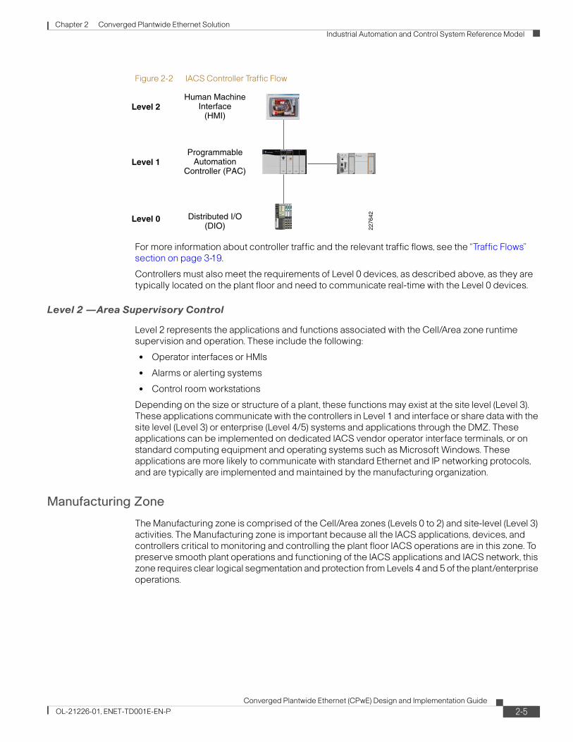
Chapter 2 Converged Plantwide Ethernet Solution Industrial Automation and Control System Reference Model
Figure 2-2 IACS Controller Traffic Flow
For more information about controller traffic and the relevant traffic flows, see the “Traffic Flows” section on page 3-19.
Controllers must also meet the requirements of Level 0 devices, as described above, as they are typically located on the plant floor and need to communicate real-time with the Level 0 devices.
Level 2 —Area Supervisory Control
Level 2 represents the applications and functions associated with the Cell/Area zone runtime supervision and operation. These include the following:
• Operator interfaces or HMIs
• Alarms or alerting systems
• Control room workstations
Depending on the size or structure of a plant, these functions may exist at the site level (Level 3). These applications communicate with the controllers in Level 1 and interface or share data with the site level (Level 3) or enterprise (Level 4/5) systems and applications through the DMZ. These applications can be implemented on dedicated IACS vendor operator interface terminals, or on standard computing equipment and operating systems such as Microsoft Windows. These applications are more likely to communicate with standard Ethernet and IP networking protocols, and are typically are implemented and maintained by the manufacturing organization.
Manufacturing Zone
The Manufacturing zone is comprised of the Cell/Area zones (Levels 0 to 2) and site-level (Level 3) activities. The Manufacturing zone is important because all the IACS applications, devices, and controllers critical to monitoring and controlling the plant floor IACS operations are in this zone. To preserve smooth plant operations and functioning of the IACS applications and IACS network, this zone requires clear logical segmentation and protection from Levels 4 and 5 of the plant/enterprise operations.
Level 2
Level 1
Level 0
ProgrammableAutomation
Controller (PAC)
Distributed I/O(DIO)
Human MachineInterface
(HMI)
2276
42
2-5Converged Plantwide Ethernet (CPwE) Design and Implementation Guide
OL-21226-01, ENET-TD001E-EN-P

Chapter 2 Converged Plantwide Ethernet Solution Industrial Automation and Control System Reference Model
Level 3—Site Level
Level 3, the site level, represents the highest level of the IACS. The systems and applications that exist at this level manage plantwide IACS functions. Levels 0 through 3 are considered critical to site operations. The applications and functions that exist at this level include the following:
• Level 3 IACS network
• Reporting (for example: cycle times, quality index, predictive maintenance)
• Plant historian
• Detailed production scheduling
• Site-level operations management
• Asset and material management
• Control room workstations
• Patch launch server
• File server
• Other domain services, e.g. Active Directory (AD), Dynamic Host Configuration Protocol (DHCP), Dynamic Naming Services (DNS), Windows Internet Naming Service (WINS), Network Time Protocol (NTP), etc.
• Terminal server for remote access support
• Staging area
• Administration and control applications
The Level 3 IACS network may communicate with Level 1 controllers and Level 0 devices, function as a staging area for changes into the Manufacturing zone, and share data with the enterprise (Levels 4 and 5) systems and applications through the DMZ. These applications are primarily based on standard computing equipment and operating systems (Unix-based or Microsoft Windows). For this reason, these systems are more likely to communicate with standard Ethernet and IP networking protocols.
Additionally, because these systems tend to be more aligned with standard IT technologies, they may also be implemented and supported by personnel with IT skill sets. These IT-skilled people may or may not belong organizationally to the IT department.
Enterprise Zone
Level 4—Site Business Planning and Logistics
Level 4 is where the functions and systems that need standard access to services provided by the enterprise network reside. This level is viewed as an extension of the enterprise network. The basic business administration tasks are performed here and rely on standard IT services. These functions and systems include wired and wireless access to enterprise network services such as the following:
• Access to the Internet Access to E-mail (hosted in data centers)
• Non-critical plant systems such as manufacturing execution systems and overall plant reporting, such as inventory, performance, etc.
• Access to enterprise applications such as SAP and Oracle (hosted in data centers)
2-6Converged Plantwide Ethernet (CPwE) Design and Implementation Guide
OL-21226-01, ENET-TD001E-EN-P

Chapter 2 Converged Plantwide Ethernet Solution Industrial Automation and Control System Reference Model
Although important, these services are not viewed as critical to the IACS and thus the plant floor operations. Because of the more open nature of the systems and applications within the enterprise network, this level is often viewed as a source of threats and disruptions to the IACS network.
The users and systems in Level 4 often require summarized data and information from the lower levels of the IACS network. The network traffic and patterns here are typical of a branch or campus network found in general enterprises where approximately 90 percent of the network traffic goes to the Internet or to data center-based applications.
This level is typically under the management and control of the IT organization.
Level 5—Enterprise
Level 5 is where the centralized IT systems and functions exist. Enterprise resource management, business-to-business, and business-to-customer services typically reside at this level. Often the external partner or guest access systems exist here, although it is not uncommon to find them in lower levels (e.g., Level 3) of the framework to gain flexibility that may be difficult to achieve at the enterprise level. However, this approach may lead to significant security risks if not implemented within IT security policy and approach.
The IACS must communicate with the enterprise applications to exchange manufacturing and resource data. Direct access to the IACS is typically not required. One exception to this would be remote access for management of the IACS by employees or partners such as system integrators and machine builders. Access to data and the IACS network must be managed and controlled through the DMZ to maintain the security, availability, and stability of the IACS.
The services, systems, and applications at this level are directly managed and operated by the IT organization.
Converged Plantwide Ethernet Architectures
The Purdue Model and ISA-99 have identified levels of operations and key zones for the IACS logical framework. In addition to the levels and zones, Cisco and Rockwell Automation include a Demilitarized zone (DMZ) between the Enterprise and Manufacturing zones as part of CPwE architecture. Emerging IACS security standards such as ISA-99, NIST 800-82, and Department of Homeland Security INL/EXT-06-11478 also include a DMZ as part of a defense-in-depth strategy. The purpose of the DMZ is to provide a buffer zone where data and services can be shared between the Enterprise and Manufacturing zones. The DMZ is critical in maintaining availability, addressing security vulnerabilities, and abiding by regulatory compliance mandates (e.g., Sarbanes-Oxley). In addition, the DMZ allows for segmentation of organizational control; for example, between the IT organization and manufacturing. This segmentation allows different policies to be applied and contained. For example, the manufacturing organization may apply security and quality-of-service (QoS) policies that are different from the IT organization. The DMZ is where the policies and organizational control can be divided.
These levels and zones form the base logical framework around which the IACS network infrastructure and services are designed for the CPwE solution (see Figure 2-3).
The following sections contain a more detailed description of each zone, including the DMZ, and their related functions and components.
2-7Converged Plantwide Ethernet (CPwE) Design and Implementation Guide
OL-21226-01, ENET-TD001E-EN-P
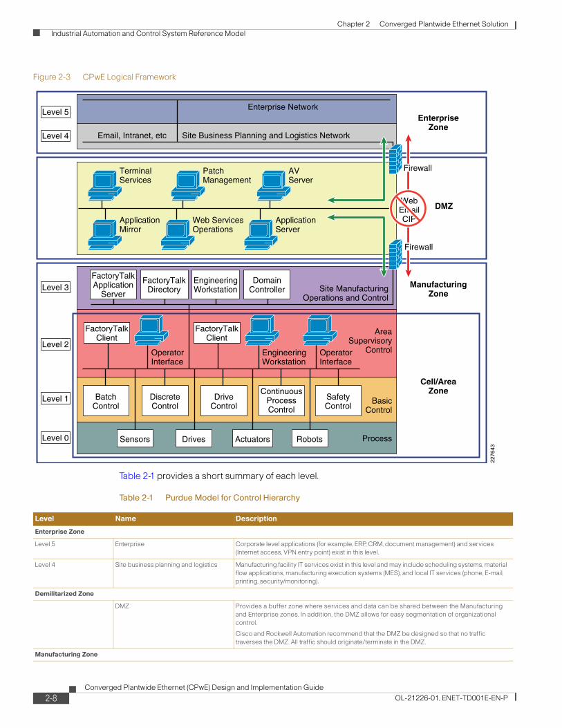
Chapter 2 Converged Plantwide Ethernet Solution Industrial Automation and Control System Reference Model
Figure 2-3 CPwE Logical Framework
Table 2-1 provides a short summary of each level.
TerminalServices
Level 5
Level 4
ApplicationMirror
Web ServicesOperations
OperatorInterface
OperatorInterface
EngineeringWorkstation
ApplicationServer
PatchManagement
Enterprise Network
Site Business Planning and Logistics NetworkEmail, Intranet, etc
AVServer
Level 3
Level 2
Level 1
Level 0
Cell/AreaZone
ManufacturingZone
DMZ
EnterpriseZone
Firewall
WebEmailCIP
Firewall
FactoryTalkClient
FactoryTalkClient
FactoryTalkApplication
Server
BatchControl
DiscreteControl
DriveControl
ContinuousProcessControl
SafetyControl
FactoryTalkDirectory
EngineeringWorkstation
DomainController Site Manufacturing
Operations and Control
AreaSupervisory
Control
BasicControl
ProcessSensors Drives RobotsActuators
2276
43Table 2-1 Purdue Model for Control Hierarchy
Level Name Description
Enterprise Zone
Level 5 Enterprise Corporate level applications (for example, ERP, CRM, document management) and services (Internet access, VPN entry point) exist in this level.
Level 4 Site business planning and logistics Manufacturing facility IT services exist in this level and may include scheduling systems, material flow applications, manufacturing execution systems (MES), and local IT services (phone, E-mail, printing, security/monitoring).
Demilitarized Zone
DMZ Provides a buffer zone where services and data can be shared between the Manufacturing and Enterprise zones. In addition, the DMZ allows for easy segmentation of organizational control.
Cisco and Rockwell Automation recommend that the DMZ be designed so that no traffic traverses the DMZ. All traffic should originate/terminate in the DMZ.
Manufacturing Zone
2-8Converged Plantwide Ethernet (CPwE) Design and Implementation Guide
OL-21226-01, ENET-TD001E-EN-P

Chapter 2 Converged Plantwide Ethernet Solution Network Reference Model
Network Reference ModelThe CPwE logical framework reflects the basic functions of an IACS. This is the key model for this CPwE solution architecture. However, as identified earlier, the goal of this architecture is to integrate the knowledge and expertise from both an IACS perspective as well as an IT perspective. An important and relevant model for network architectures is the Cisco Enterprise Campus network. The Enterprise Campus solution architecture incorporates key networking concepts and models. The CPwE solution architecture comprises many of the concepts and models of the enterprise Campus solution architecture, although it does not incorporate the entire scope of that solution, because not all concepts are applicable to IACS networks. In essence though, the IACS network can be viewed as a specialized Campus network.
This section briefly introduces the Campus network and some of the key concepts of its solution architecture. The Cisco Enterprise Campus network combines a high-availability core infrastructure of intelligent switching and routing with an overlay of productivity-enhancing technologies, including IP communications, mobility, and advanced security. This DIG refers to the Campus network documentation and the concept of core, distribution and access. Figure 2-4 shows a hierarchical design model that has proven to be effective in a campus environment, consisting of three main layers: core, distribution, and access.
Level 3 Site manufacturing operations and control
Includes the functions involved in managing the work flows to produce the desired end products. Examples include detailed production scheduling, reliability assurance, site-wide control optimization, security management, network management, and potentially other required IT services such as DHCP, LDAP, DNS, and file servers.
Cell/Area Zone
Level 2 Area supervisory control Control room, controller status, IACS network/application administration, and other control-related applications (supervisory control, historian)
Level 1 Basic control Multidiscipline controllers, dedicated HMIs, and other applications may talk to each other to run a part or whole IACS.
Level 0 Process Where devices (sensors, actuators) and machines (drives, motors, robots) communicate with the controller or multiple controllers.
Safety Zone
Safety-critical Devices, sensors, and other equipment used to manage the safety functions of an IACS.
Table 2-1 Purdue Model for Control Hierarchy (continued)
Level Name Description
2-9Converged Plantwide Ethernet (CPwE) Design and Implementation Guide
OL-21226-01, ENET-TD001E-EN-P
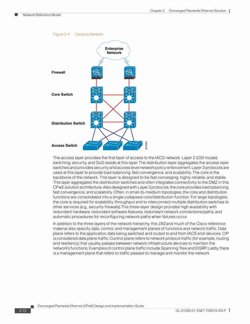
Chapter 2 Converged Plantwide Ethernet Solution Network Reference Model
Figure 2-4 Campus Network
The access layer provides the first layer of access to the IACS network. Layer 2 (OSI model) switching, security, and QoS reside at this layer. The distribution layer aggregates the access layer switches and provides security and access level network policy enforcement. Layer 3 protocols are used at this layer to provide load balancing, fast convergence, and scalability. The core is the backbone of the network. This layer is designed to be fast converging, highly reliable, and stable. This layer aggregates the distribution switches and often integrates connectivity to the DMZ in this CPwE solution architecture. Also designed with Layer 3 protocols, the core provides load balancing, fast convergence, and scalability. Often, in small-to-medium topologies, the core and distribution functions are consolidated into a single collapsed core/distribution function. For large topologies, the core is required for scalability, throughput and to interconnect multiple distribution switches to other services (e.g., security firewalls).This three-layer design provides high availability with redundant hardware, redundant software features, redundant network connections/paths, and automatic procedures for reconfiguring network paths when failures occur.
In addition to the three layers of the network hierarchy, this DIG and much of the Cisco reference material also specify data, control, and management planes of functions and network traffic. Data plane refers to the application data being switched and routed to and from IACS end-devices. CIP is considered data plane traffic. Control plane refers to network protocol traffic (for example, routing and resiliency) that usually passes between network infrastructure devices to maintain the network's functions. Examples of control plane traffic include Spanning Tree and EIGRP. Lastly, there is a management plane that refers to traffic passed to manage and monitor the network
Core Switch
Firewall
Distribution Switch
Access Switch22
7644
EnterpriseNetwork
2-10Converged Plantwide Ethernet (CPwE) Design and Implementation Guide
OL-21226-01, ENET-TD001E-EN-P

Chapter 2 Converged Plantwide Ethernet Solution Network Reference Model
infrastructure and services, an example of which would be SNMP or SSH traffic to monitor the switches and routers. These protocols may also be communicated to and from servers and other endpoints in the network.
In addition to the high availability switching and routing network, the Enterprise Campus architecture incorporates the following three core networking functions:
• Network security based on the Cisco Self-Defending network
• IP-based communications
• Mobility and wireless LAN services (not addressed in this version of the CPwE solution architecture)
For more information on the Enterprise Campus network, refer to the following URLs:
• Enterprise Campus Architecture: Overview and Framework
http://www.cisco.com/en/US/docs/solutions/Enterprise/Campus/campover.html
• Campus Network for High Availability Design Guide
http://www.cisco.com/en/US/docs/solutions/Enterprise/Campus/HA_campus_DG/hacampusdg.html#wp1107563
AccessThe access layer is the first tier or edge of the Campus network. It is the place where IACS network devices (PCs, servers, controllers, I/O devices, drives, etc.) attach to the wired portion of the IACS network. The wide variety of possible types of devices that can connect and the various services and dynamic configuration mechanisms that are necessary, make the access layer one of the IACS feature-rich parts of the Campus network. Table 2-2 lists examples of the types of services and capabilities that need to be defined and supported in the access layer of the IACS network.
The access layer provides the intelligent demarcation between the network infrastructure and the devices that leverage that infrastructure. As such, it provides a security, QoS, and policy trust boundary. When looking at the overall IACS network design, the access switch provides the majority of these access-layer services and is a key element in enabling multiple IACS network services.
The Cell/Area zone can be considered an access layer network specialized and optimized for IACS networks.
Table 2-2 Examples of Types of Service and Capabilities
Service Requirements Service Features
Discovery and Configuration Services 802.1AF, CDP, EtherNet/IP CNA, SNMP, CIP Support
Security Services IBNS (802.1X), DHCP snooping
Network Identity and Access DHCP Server, 802.1X
Application Recognition Services QoS marking, policing, queuing,
Intelligent Network Control Services Rapid PVST+, MSTP, EtherChannel/LACP, UDLD, Flex Link, Portfast, LoopGuard, BPDUGuard, Port Security, RootGuard, IGMP Snooping/Querier
2-11Converged Plantwide Ethernet (CPwE) Design and Implementation Guide
OL-21226-01, ENET-TD001E-EN-P

Chapter 2 Converged Plantwide Ethernet Solution Network Reference Model
DistributionThe distribution layer in the Campus design has a unique role in that it acts as a services and control boundary between the access and the core. Both access and core are essentially dedicated special purpose layers. The access layer is dedicated to meeting the functions of end-device connectivity and the core layer is dedicated to providing non-stop connectivity across the entire IACS network. The distribution layer, on the other hand, serves multiple purposes. It is an aggregation point for all of the access switches and acts as an integral member of the access-distribution block providing connectivity and policy services for traffic flows within the access-distribution block (for example, Cell/Area to Cell/Area communication). It is also an element in the core of the network and participates in the core routing design. Its third role is to provide the aggregation, policy control, and isolation demarcation point between Cell/Area zone and the rest of the IACS network. Using a software analogy, the distribution layer defines the data input and output between a subroutine (distribution) and the mainline of the program (core). It defines a summarization boundary for network control plane protocols (EIGRP, OSPF, and Spanning Tree) and serves as the policy boundary between the devices and data flows within the access-distribution block and the rest of the network. In providing all these functions, the distribution layer participates in both the access-distribution block and the core. As a result, the configuration choices for features in the distribution layer are often determined by the requirements of the access layer or the core layer, or by the need to act as an interface to both.
The function of the distribution layer is discussed in more detail in the description of the access-distribution block and the associated design sections.
CoreThe core in some ways is the simplest, but the critical part of the plant network. It provides a very limited set of services and is designed to be highly available and operate in an always-on mode. The key design objectives for the core are based on providing the appropriate level of redundancy to allow for near immediate data-flow recovery in the event of any component (switch, supervisor, line card, or fiber) failure. The network design must also permit the occasional, but necessary, hardware and software upgrade/change to be made without disrupting any network applications. The core of the network should not implement any complex policy services, nor should it have any directly attached user/server connections. The core should also have the minimal control plane configuration combined with highly available devices configured with the correct amount of physical redundancy to provide for this non-stop service capability.
Table 2-3 Examples of Types of Service and Capabilities
Service Requirements Service Features
Discovery and Configuration Services 802.1AF, CDP CNA, SNMP
Security Services ACLs, IBNS (802.1X), DHCP snooping
Network Identity and Access IP Helper, DHCP Server, 802.1x
Application Recognition Services QoS marking, policing, queuing
Intelligent Network Control Services Rapid PVST+, MSTP, EtherChannel/LACP, UDLD, Flex Link, Portfast, LoopGuard, BPDUGuard, Port Security, RootGuard, IGMP Snooping/Querier
IP Routing (EIGRP or OSPF), HSRP, Multicast routing PIM
2-12Converged Plantwide Ethernet (CPwE) Design and Implementation Guide
OL-21226-01, ENET-TD001E-EN-P

Chapter 2 Converged Plantwide Ethernet Solution Network Reference Model
The core is the backbone that glues together all the elements of the Manufacturing zone. It is that part of the network that provides for connectivity between end-devices, server-based applications, data storage—and connects to the Demilitarized zone for connectivity to the Enterprise zone. It serves as the aggregator for all of the other plant Cell/Area zones. Some of the key services available on the core platform include those shown in Table 2-4.
Note that, in many network designs, core switches are used to integrate Wide-Area Network (WAN) connections that are typically used in the Enterprise network. WAN connectivity is a distinct consideration not covered in this version of the solution. WAN connectivity may require support of a wider range of physical interfaces and support for technologies such as MPLS. For more information on WAN architectures and support, see Design Zone for WAN/MAN at the following URL: http://www.cisco.com/en/US/netsol/ns817/networking_solutions_program_home.html.
One question that must be answered when developing a campus design is this: Is a distinct core layer required? In small-to-medium plants, it is possible to collapse the core into the two distribution switches as shown in Figure 2-5. However, for large plants, where a large number of Cell/Area zones exist, this level of hierarchical segmentation is recommended.
More detailed guidance on this topic is provided in Chapter 4, “CPwE Solution Design—Manufacturing and Demilitarized Zones.”
Figure 2-5 Collapsed Distribution and Core Campus
Table 2-4 Examples of Types of Service and Capabilities
Service Requirements Service Features
Discovery and Configuration Services 802.1AF, CDP, CNA, SNMP
Security Services ACLs, IBNS (802.1X), DHCP snooping, Router protocol protection
Network Identity and Access IP Helper, DHCP Server, 802.1x
Application Recognition Services QoS marking, policing, queuing
Intelligent Network Control Services Spannig Tree Protocols, EtherChannel/LACP, UDLD, IP Routing (EIGRP or OSPF), HSRP, Multicast routing PIM, MPLS
Core/DistributionSwitch
Access Switch
2276
45
EnterpriseNetwork
Firewall
2-13Converged Plantwide Ethernet (CPwE) Design and Implementation Guide
OL-21226-01, ENET-TD001E-EN-P
Chapter 2 Converged Plantwide Ethernet Solution CPwE—Converging Reference Models
CPwE—Converging Reference ModelsThe overall objective of this CPwE solution is convergence of the IACS applications and networks with the enterprise systems and networks. To that end, this CPwE Design and Implementation Guide blends reference model terms and concepts from Campus, OSI, and the Six-Level Logical Plant architecture into both the CPwE Logical Framework shown in Figure 2-3 and the CPwE architecture shown in Figure 2-6. This section provides description on how some of these key terms are used.
The Cell/Area zone contains IACS devices from Levels 0 to 2. A device belongs to a single Cell/Area network. The Cell/Area IACS network is essentially a Layer-2 network, meaning that the MAC address of the IACS device is used to forward (switch) Implicit I/O and Explicit message traffic from the IACS device throughout the Cell/Area zone. A Layer-2 network also refers to a subnet, broadcast domain and a virtual LAN (VLAN). Cisco and Rockwell Automation recommend that there is a 1:1:1 relationship between subnets, broadcast domains. and VLANs. The Layer-2 network infrastructure devices in the Cell/Area zone are predominantly access switches. The ports on a distribution switch that aggregates the access switches are also typically part of the Layer-2 network and therefore considered part of the Cell/Area zone. The distribution switches in this document are depicted on the demarcation between the Manufacturing and Cell/Area zone as depicted in Figure 2-6. The distribution switch is also the Layer 2 to Layer 3 demarcation. There will be multiple Cell/Area zones within most plants.
The Manufacturing zone is analogous to a Campus network; many plants will have a single Manufacturing zone. The Manufacturing zone will have multiple Layer-2 networks, which may be Cell/Area zones or Level 3 IACS networks to connect Level 3 applications. The Manufacturing zone also has Layer-3 functions that forward IACS device traffic based upon the IP address. These Layer-3 functions are represented in the distribution and core functions described in the Campus reference model. The Manufacturing zone consists of IACS applications and network infrastructure including the following:
• All Cell/Area zones—IACS applications and Layer-2 networks
• Level 3, Plantwide IACS applications and devices
• Layer-2 networks and access switches to provide network connectivity to the Level 3 devices.
• Layer-3-capable distribution and core switches (or routers) that provide interconnectivity between Cell/Area zones, the DMZ, and any Manufacturing zone Layer-2 networks.
The Demilitarized zone (DMZ) is a zone between the Manufacturing and the Enterprise zones to securely manage the traffic flow between these networks. A plant firewall is implemented to manage the traffic flow and establish the DMZ.
2-14Converged Plantwide Ethernet (CPwE) Design and Implementation Guide
OL-21226-01, ENET-TD001E-EN-P

Chapter 2 Converged Plantwide Ethernet Solution CPwE—Converging Reference Models
Figure 2-6 CPwE Overall Architecture
FactoryTalk Application
Servers
Enterprise ZoneLevels 4 and 5
Cell/Area ZoneLevels 0–2
CoreSwitches
Firewall(Standby)
Firewall(Active)
Patch ManagementTerminal ServicesApplication MirrorAnti-Virus Server Link for
FailoverDetection
HMILayer 2,Industrial Ethernet Access Switches
Cell/Area(Ring Topology)Controller
VFD
Manufacturing ZoneLevel 3
Internet
Demilitarized Zone (DMZ)
Stacked Layer 3Distribution Switch
EtherNet/IP traffic Real-time Control Traffic segmentation, prioritization and management Resiliency with fast Network Convergence
Stacked Layer 3 Access/Distribution Switch
NetworkServices
Remote AccessServer
Layers 2 & 3, Access, Distribution and Core Network Infrastructure
Layer 2, Access NetworkInfrastructure
Site Operations and ControlMulti-service NetworkRoutingSecurity and Network ManagementApplications
Firewalls for segmentationUnified Threat Management (UTM)Authentication and authorizationApplication and Data Sharing viareplication or terminal servicesAccess
Switch
WAN and Internet networkData CentersEnterprise Security and Network Management Enterprise Resource Planning (ERP)Applications
EnterpriseWAN
External DMZ/Firewall
Enterprise WANRouters
2-15Converged Plantwide Ethernet (CPwE) Design and Implementation Guide
OL-21226-01, ENET-TD001E-EN-P

Chapter 2 Converged Plantwide Ethernet Solution CPwE—Converging Reference Models
2-16Converged Plantwide Ethernet (CPwE) Design and Implementation Guide
OL-21226-01, ENET-TD001E-EN-P

Converged Plantwide Ethernet (CPwOL-21226-01, ENET-TD001E-EN-P
C H A P T E R 3
CPwE Solution Design—Cell/Area ZoneOverviewThe Industrial Automation and Control Systems (IACS) network within the Cell/Area zone is the major building block of the CPwE architecture. This is the network that connects sensors, actuators, drives, controllers and any other IACS devices that need to communicate in real-time (I/O communication). This chapter outlines the key requirements and technical considerations for the Cell/Area zone and related IACS applications. Chapter 2, “Converged Plantwide Ethernet Solution”outlined the general constitution and characteristics of the Cell/Area zone.
It is important to consider the Cell/Area zone as a separate entity of the Manufacturing zone. For most industrial applications, the Cell/Area zone is where the primary IACS activities are performed. The availability and performance requirements are most distinct in the Cell/Area zone. These requirements are different than those typically found in an IT network. In summary, the key design considerations are as follows:
• Industrial Characteristics—The environmental conditions of the plant floor must be taken into consideration because the equipment must be able to perform in these conditions. This drives the industrial characteristics of all the equipment, including the network infrastructure. The network topology must be shaped to fit appropriately into the plant floor environment.
• Interconnectivity and interoperability—Standardization on a single vendor's IACS or industrial Ethernet network equipment within the Cell/Area zone may not be practical. For this reason, CPwE network design for the Cell/Area zone will consider and evaluate standard Ethernet and IP networking technologies to help provide the greatest opportunity for interconnectivity and interoperability within a mixed-vendor IACS environment.
• Real-time communications and network performance—Cell/Area IACS network must be designed to meet the latency and jitter requirements of the IACS it supports. This can impact the size of the LAN, the number of routing hops, the VLAN configuration, and a number of other network parameters.
• Availability—The availability of the Cell/Area zone is critical to the manufacturing process. Without a properly functioning Cell/Area IACS network, some or all of the plant operations may come to a halt. This can severely impact plant efficiency and the manufacturer's bottom line. Availability itself is a function of equipment, infrastructure, configuration, software, etc. This chapter discusses how the network resiliency can support various IACS applications so network developers can choose a design with a clear understanding of the capability of the Cell/Area IACS network. For example, the network must also be able to recover from network
3-1E) Design and Implementation Guide

Chapter 3 CPwE Solution Design—Cell/Area Zone Overview
impacting events, such as a connection break, faster than the cycle time of the IACS to avoid the system automatically shutting down. Availability impacts the network design, topology, and even the type of network infrastructure used.
• Manageability—plant floor is usually not supported in the same manner as an IT network. The plant floor maintenance personnel tend not to have the same networking experience as IT. The setup and maintenance of network equipment and configuration must be simplified to meet the experience level of the plant floor maintenance personnel.
• Security—IACS/IT network convergence calls for evolved security policies for industrial networks which no longer remain isolated. IACS assets have become susceptible to the same security vulnerabilities (for example, denial of service) as their enterprise counterparts. Protecting IACS assets requires a defense-in-depth security approach to assure the availability, confidentiality and integrity of IACS data.
• Unmanaged versus managed—Although the cost of the network infrastructure may not represent a large proportion of the plant floor, the same cost reduction mentality is often applied as to other aspects of the manufacturing facility. Without clear understanding of the qualities of a managed, intelligent network, the additional hardware costs they represent may lead network developers to choose less intelligent solutions based purely on initial cost considerations; only later do they determine that the cheaper, unmanaged infrastructure cannot scale, perform, integrate, or be as easily maintained as an intelligent, managed network.
All these factors directly impact the IACS components, network topology, drive particular requirements of the Cell/Area zone IACS network design.
The Cell/Area zone is also distinct in that most of the network communication is of a local nature-one device communicating with another in the same vicinity. From a network perspective, the Cell/Area zone correlates primarily with a Layer 2, or local area network (LAN), network. In the campus design, the Cell/Area zone aligns with the access-layer and many of the recommendations and considerations are applied, albeit with a consideration for the plant floor and the IACS applications. Therefore, this chapter applies as a rule Layer 2 functions and some relevant Layer 3 concepts to the Cell/Area IACS network design.
This chapter discusses how the following key network functions are applied to the Cell/Area zone:
• Component selection
• Topology and media considerations
• Resiliency protocols
• Logical segmentation and virtual LANs (VLANs)
• Multicast management
• Quality-of-service (QoS)
• Security
• Scalability
This chapter describes the key requirements and considerations in detail and then provides network design recommendations and options to meet those requirements. The Cisco and Rockwell Automation CPwE solution recommendations can be summarized as follows:
• Design small Cell/Area zones in a VLAN to better manage and shape the traffic.
• Use managed switches (diagnostics, segmentation, prioritization, resiliency, and security).
• All connections should be auto-negotiate for speed and duplex and thereby apply full-duplex communication to avoid collisions.
3-2Converged Plantwide Ethernet (CPwE) Design and Implementation Guide
OL-21226-01, ENET-TD001E-EN-P

Chapter 3 CPwE Solution Design—Cell/Area Zone Key Requirements and Considerations
• Use fiber Gigabit Ethernet ports for trunks/uplinks for distance, quick recovery, lower latency, and jitter.
• Use IGMP snooping/querier functions to control multicast traffic volume, preferably with the querier on the Layer-3 distribution switch.
• Use resilient network topologies, ring, or redundant star:
– For redundant star topologies, use Flex Links on the industrial Ethernet (IE) switch for fastest failover.
– In ring topologies, use per-VLAN Multiple Spanning Tree Protocol (MSTP) to manage loops and recover from connectivity loss for network convergence. Strategically configure the Spanning Tree Root function, preferably on the distribution switch.
• Understand the availability requirements of the manufacturing process and IACS to properly select, design and implement the network resiliency capabilities. The selected network resiliency may or may not meet these requirements depending on the type of IACS application. Implementer should design the IACS systems appropriately and understand the implications of a network event on the IACS applications.
• Apply port security to Layer-2 industrial Ethernet switch to limit use of open ports.
Key Requirements and ConsiderationsThis section expands on the key requirements and considerations summarized at the beginning of this chapter, which the network design recommendations for the Cell/Area zone are based on. These requirements and considerations are in alignment with the overall solution requirements outlined in Chapter 1, “Converged Plantwide Ethernet Overview.” For each requirement, the network design characteristics that combine to meet those requirements are listed.
Industrial CharacteristicsThe Cell/Area zone interconnects devices closest to the manufacturing process and extends into most areas of the plant environment. Therefore, the design of the Cell/Area zone must meet the industrial characteristics of the plant floor. This includes the following:
• The network infrastructure must be able to operate in the plant floor conditions. This directly impacts the choice of network infrastructure, especially whether or not common-of-the-shelf (COTS) equipment can be used.
• The network topology must be flexible enough to interconnect the devices and infrastructure based upon the constraints of the plant floor layout. This requirement basically suggests that the solution must support a variety of network topologies, including ring, redundant star, and linear/star. These topologies are the most prevalent in IACS networking.
The plant environment also impacts the selection of the network media used to interconnect devices and the network infrastructure. This section does not cover this aspect of the network design. However, the choice of network media can dictate the use of specific network infrastructure components like specific switches and routers; not all components, for example supports a fiber media. Conversely, the choice of network media also has an impact on network availability and resiliency. This section discusses the use of copper versus fiber media, but does not identify when one or the other should be used based upon the industrial characteristics. For more information on the impact of fiber versus copper on network availability and resiliency, see the “Fiber Versus Copper Cabling” section on page 3-29.
3-3Converged Plantwide Ethernet (CPwE) Design and Implementation Guide
OL-21226-01, ENET-TD001E-EN-P

Chapter 3 CPwE Solution Design—Cell/Area Zone Key Requirements and Considerations
The system industrial characteristics influence these design factors:
The industrial characteristics are reflected in the following design considerations:
1. Network infrastructure component choice
2. Topology and media considerations
Interconnectivity and InteroperabilityThe Cell/Area zone is generally comprised of IACS devices communicating primarily in a Layer-2 local network model. Interconnectivity and interoperability requirements essentially include the following:
• Interconnectivity between the IACS devices—The basic networking considerations of the CPwE solution supports any application or protocols based upon use of unmodified, standard Ethernet and the IP protocol suite in the network infrastructure. Considering the most common IACS networks/protocols where common, unmodified standard networking infrastructure can be applied (for example, such as EtherNet/IP (CIP), Modbus TCP, and certain versions of Profinet). Other protocols use a combination of software or hardware modifications that must be incorporated into the network infrastructure using non-standard switching infrastructure or network interface cards. Interconnectivity means that the IACS network devices can communicate using standard protocols at Layers 2, 3, and 4 (Ethernet, IP, and TCP/UDP). Interoperability means that the IACS network devices can interoperate using standard, common protocols at Layer 7 (application). IACS devices with different application-layer protocols may not interoperate without some gateway device/service to perform an application-layer translation. This CPwE solution is based upon the use of the Common Industrial Protocol (CIP) as the common application-layer protocol for IACS network interoperability employing EtherNet/IP as the IACS network.
Other protocols are used in a typical IACS network. These are typically based on the deployment of unmodified, standard Ethernet and IP network infrastructure. Such protocols include TCP/IP, DHCP, HTTP, HTTPS, SSH, Telnet, FTP, etc. This CPwE solution supports these protocols, as long as they are based upon the common standard Ethernet and IP technologies.
• Interoperability of the network infrastructure—This DIG primarily focuses on the use of Cisco and Rockwell Automation network infrastructure and therefore does not specifically test or include guidance for interoperability with other network infrastructure vendor's equipment. However, one of the objectives of this CPwE solution was to evaluate the use of standard network functions and protocols so that network developers can choose to use those technologies for interoperability requirements. This solution also considers proprietary protocols and functions that may better meet IACS requirements. This solution guide provides design guidance so that network developers can appropriately choose between standard and, in some cases, proprietary technologies. Cisco and Rockwell Automation are committed to using standards and growing the standards base by introducing their technologies into the relevant bodies to increase the take-up by the market.
To this end, this chapter includes the consideration and evaluation of the following standard features and functions:
• Topology—Redundant star, ring, star/bus/linear
• Resiliency—MSTP (originally defined in IEEE 802.1s and later merged into IEEE 802.1Q-2003), Flex Links, EtherChannel (Link Aggregation Control Protocol (LACP)) for network resiliency
• IGMP for multicast management
• Virtual LANs (VLANs)
3-4Converged Plantwide Ethernet (CPwE) Design and Implementation Guide
OL-21226-01, ENET-TD001E-EN-P

Chapter 3 CPwE Solution Design—Cell/Area Zone Key Requirements and Considerations
• Quality-of-service (QoS)
The implementation of these network features and functions is also considered in Chapter 5, “Implementing and Configuring the Cell/Area Zone.”
This solution does not recommend or consider the incorporation of unmanaged switches. Use of these switches in combination with managed switches with these features implemented may leave the IACS exposed to security risks, degrade the performance, and quality of the network services and may cause problems including network and system outages.
Interconnectivity and interoperability of the Cell/Area zone with IACS applications and equipment in other Cell/Area zones or devices and applications in the Manufacturing zone is in the scope of this solution. For details, refer to the “Manufacturing Zone” section on page 4-1.
Real-Time Communication, Determinism, and PerformanceDeterminism, or the predictability of performance, is a key requirement for industrial networks, especially for device-level control and controller interlocking (implicit traffic in CIP model) in the Cell/Area zone. Determinism is a system-wide characteristic where the network is one of many factors that determine how deterministic a system is. The network’s main impact on a system’s determinism is based on the following network performance characteristics:
• Latency—The average amount of time a message takes to be transmitted and processed from originating node to destination node
• Jitter—The amount of variance in the latency
IACS networks need to have low levels of latency and jitter, and reliable data transmission to support real-time applications that have cycle times of less then 50ms and motion control applications that have cycle times of less then 1ms.
The IACS network solution architecture should incorporate mechanisms to indicate whether the network is maintaining the required real-time characteristics and thereby its impact on the overall deterministic condition of the system. If the data transmission is not repeatable, predictable, and reliable, the IACS may not function properly. Achieving this performance level is the fundamental requirement for successful Ethernet deployments to the device level. An important objective of the CPwE solution is to accomplish the following:
1. Show the impact that network characteristics have on the IACS network latency and jitter as well as network packet loss.
2. Recommend network functions to maintain the system’s determinism as the network load/performance changes.
Packet loss also impacts availability as the loss of too many packets leads to system errors or shutdowns. For more information on availability requirements, refer to the “Availability and Network Resiliency” section on page 3-41 and the “Quality-of-Service (QoS)” section on page 3-63 for techniques to reduce packet loss.
In IACS implementations, the application’s real-time requirements vary considerably depending on the underlying process or system. The IACS network real-time requirements are usually defined as follows:
• Machine/process cycle times—The frequency with which the IACS application makes decisions
• Request Packet Interval (RPI) or I/O update time—The frequency which input/outputs are sent/received
3-5Converged Plantwide Ethernet (CPwE) Design and Implementation Guide
OL-21226-01, ENET-TD001E-EN-P

Chapter 3 CPwE Solution Design—Cell/Area Zone Key Requirements and Considerations
• Packet-loss tolerance—The number of consecutive packet intervals before an application errors or fails
These input/outputs are usually CIP Implicit I/O (UDP unicast or multicast) messages between a controller and IACS device or between two controllers. Network developers can also specify controller-to-controller interlock messages to be sent via UDP unicast, and these messages can be routed to controllers in other VLANs/subnets. Other messages, for example CIP Explicit messages, are not as critical and do not have the same low-latency, low-jitter, and minimal packet-loss requirements.
For the purposes of providing design and implementation guidance, Cisco and Rockwell Automation defined a set of requirements characterized by a general class of applications in Table 3-1.
The objective of developing this table was to show how the network characteristics impact the IACS application, and in particular the Information and time-critical I/O (process and discrete) requirement class. This version of the CPwE solution does not focus on providing the real-time qualities required by Safety and Motion applications implementing CIP Safety™, CIP Motion™, and CIP Sync™.
The objective in this release of the CPwE solution is to provide network recommendations to help achieve these real-time requirements. The key network characteristics that impact system (as well as network) latency and jitter include the following:
• Number of Ethernet nodes (end-devices) on the network
• Number of switches (hops) in the network
• Traffic volume due to broadcast and multicast traffic
• Network convergence of resiliency protocols
• Network bandwidth utilization
• Switch resource utilization
In this version of the CPwE DIG, system test results are provided that correlate a system's latency and jitter to the number of switches (hops) in a given Cell/Area zone. To provide this information, screw-to-screw tests were designed to measure system latency and jitter. These tests were performed and analyzed in a number of system topologies. Their results are summarized in the “Scalability” section on page 3-84 and “Network Design Recommendations” section on page 3-10. The detailed test results are available in Appendix C, “Complete Test Data” and a short analysis is available in Appendix B, “Test Result Analysis.”
Table 3-1 IACS Application Real Time Requirements
Requirement Class Typical Cycle Time Typical RPI Connection Timeout
Information/Process (e.g. HMI) < 1 s 100 - 250 ms Product dependent
For example, 20 seconds for RSLinx
Time critical processes (e.g. I/O) 30 - 50 ms 20 ms 4 intervals of RPI, but =100 ms
Safety 10 - 30 ms 10 ms 24 – 1000 ms
Motion 500 μs - 5ms 50 μs - 1 ms 4 intervals
3-6Converged Plantwide Ethernet (CPwE) Design and Implementation Guide
OL-21226-01, ENET-TD001E-EN-P

Chapter 3 CPwE Solution Design—Cell/Area Zone Key Requirements and Considerations
AvailabilityIn the Cell/Area zone, the critical IACS equipment that keeps the plant operational is interconnected through the IACS network infrastructure. In this application network, availability is a major requirement. Every major design decision is made balancing availability with cost considerations. These considerations increase overall equipment effectiveness (OEE) by reducing the impact of a failure, and they speed recovery from an outage that lowers mean-time-to-repair (MTTR). The considerations elaborated later in this chapter include the following:
• Equipment choice-the level of availability of the network is only as good as the components that make up the infrastructure. In general, the following factors should be considered:
– Industrial characteristics to reduce the MTTR
– Ease and efficiency of replacement features to reduce impact of a failure
– Support for network features and functions related to overall availability (for example, resiliency protocols supported)
• Eliminate single points of failure in the network infrastructure especially devices in critical roles, (for example, having redundant distribution and core switches).
• Multiple paths in the network uplink cabling (using variants of the redundant star or ring topologies).
• Resilient network protocols in place to meet application tolerance requirements to packet loss and application connection timeouts.
• Applying a QoS approach to protect and prioritize key IACS traffic.
• Segmentation to limit the impact of a failure or breach.
• Show the impact of network characteristics, such as network convergence, has on the application, like CIP Implicit I/O connection timeout.
• Multicast management to limit the impact of multicast messages on the network and end-devices.
• Employ network resiliency methods to reduce the risk of application shutdowns. For example, employing network convergence techniques can prevent CIP Implicit I/O connection timeouts.
• Where multicast is used, implement multicast management to limit the impact of multicast messages on the network and end-devices.
It is challenging, in a lab or in a manufacturing environment, to identify and measure the overall impact many of these considerations have on availability and operational efficiency. The cost of downtime varies widely in manufacturing environments. However, the above points are generally considered best practices and in many cases are worth the additional investment.
In the end though, the critical factor is whether the IACS applications continue to operate given any specific outage or failure. There is also a relationship between the availability and what is referred to as the deterministic requirements. An IACS system will fail or timeout when the network is unavailable for a certain period of time. That period of time is directly related to the level of determinism required by the IACS. For example, a requested packet interval (RPI) from a Rockwell Automation controller to its I/O device might be 25 ms. The default timeout for this connection would be 100ms—if the controller does not hear from the device in 100ms, the connection is timed out, an error is indicated and quite possibly the application is disrupted-depending on how the system was designed. Table 3-2 outlines the target network convergence (defined in Appendix A, “Key Terms and Definitions”) times where the application will not timeout if network services are restored in that time period.
3-7Converged Plantwide Ethernet (CPwE) Design and Implementation Guide
OL-21226-01, ENET-TD001E-EN-P

Chapter 3 CPwE Solution Design—Cell/Area Zone Key Requirements and Considerations
As with the determinism requirements, the network convergence is highly application-specific. The cycle times, RPIs, and type of application vary greatly and, therefore, the required network convergence. The “Network Design Recommendations” section on page 3-10 provides design and implementation guidance based on experience from the field as well as testing in the lab configuration on whether and how to achieve these objectives based upon key parameters such as the following:
• Topology used
• Network resiliency protocol used
• Type of network media used
• Number of Ethernet nodes (end-devices) on the network
• Number of multicast addresses in use (roughly the number of I/O connections)
• Number of switches (hops) in the network
• Network bandwidth utilization
The guidance provided in this CPwE DIG is based on the objectives above, but is meant only as guidance to network developers implementing this technology. Network developers must decide how they use the network resiliency capability. For example, if the network converges from a fault fast enough to avoid application faults, the network developer must determine how long the system should operate with the fault. Network developers may choose a certain design knowing that the network resiliency may not always converge fast enough to avoid application faults, but may be interested in having the network recover quickly so as to speed recovery from any resulting outages or having certain aspects of the IACS application continue to function while other applications fault. In addition, the detailed test results in is provided in Appendix C, “Complete Test Data” to allow network developers to review and analyze the solution testing results to better determine what they can expect in their particular situation.
SecuritySecurity is a feature prevalent throughout this CPwE solution, including the Cell/Area zone. As the Cell/Area zone is in many ways an access-layer and Layer 2 network, the security requirements and considerations are focused on that perspective. Chapter 6, “IACS Network Security and the Demilitarized Zone” provides an overview of security as well as focus on particular security-related capabilities (for example, remote access).
For the Cell/Area zone design, the following are the security requirements:
1. Secure network access. Essentially, allow valid devices to access the network and limit or deny non-valid devices network access so they cannot easily interrupt the IACS applications.
2. Protecting key Cell/Area IACS network infrastructure and functions. This is essentially about how the network protects itself and its key functions.
Table 3-2 Network Convergence targets
Requirement Class Target Cycle Time Target RPI Target Network Convergence
Information/Process (e.g. HMI) < 1 s 100 - 250 ms < 1 sec
Time critical processes (e.g. I/O) 30 - 50 ms 20 ms < 100 ms
Safety 10 - 30 ms 10 ms < 24 ms
Motion 500 μs - 5ms 50 μs - 1 ms < 1ms
3-8Converged Plantwide Ethernet (CPwE) Design and Implementation Guide
OL-21226-01, ENET-TD001E-EN-P

Chapter 3 CPwE Solution Design—Cell/Area Zone Key Requirements and Considerations
The purpose of the security design is to provide these functions to protect the Cell/Area zone from intentional or unintentional attacks. The security design for the Cell/Area zone looks at the following types of attacks:
• Inappropriate access to network infrastructure
• Spanning Tree attack
• MAC flooding
• MAC spoofing
• VLAN hopping
• VLAN tagging
• DHCP starvation
• Rogue DHCP
The Cell/Area zone security section outlines how these attacks can be mitigated and summarize the network security. The security requirements are also discussed in the following sections of the Cell/Area zone design:
• Network component selection
• Logical segmentation and VLANs
• Availability and network resiliency
• Quality-of-Service (QoS)
ManageabilityManageability is a significant issue for the IACS network, but especially for the Cell/Area zone. Control engineers or maintenance personnel, with varying degrees of industrial Ethernet networking expertise, are more likely to have some or all responsibility for the network operations and performance in the Cell/Area zone. Furthermore, issues in the Cell/Area zone have direct operational impact on the plant. Control engineers and maintenance personnel want access to and information about the health of the network when issues arise, even if the network is not the source of the issue. Manageability is a key source of requirements and considerations including the following:
• Easy to deploy, configure, monitor, and maintain the network infrastructure.
• Accessible via common tools and applications and the ability to integrate network status and configuration into the IACS system.
In this section, manageability is considered in the following network design areas:
• Network component selection
• Segmentation and VLANs
• Network security
ScalabilityCell/Area zone scalability is a debatable quality. In general, Cisco and Rockwell Automation recommend smaller VLANs and Cell/Area zones to manage network performance and improve overall security. Scaling for large plants and numbers of devices is a function of the Manufacturing zone, which interconnects the presumed larger number of Cell/Area zones. Nonetheless, it is
3-9Converged Plantwide Ethernet (CPwE) Design and Implementation Guide
OL-21226-01, ENET-TD001E-EN-P
Chapter 3 CPwE Solution Design—Cell/Area Zone Network Design Recommendations
understood that certain plant floor scenarios may require larger Cell/Area zones. Therefore, this CPwE solution provides guidance for limitations on the size of a Cell/Area zone. The size of a Cell/Area zone is an inverse relationship with the following system characteristics:
• Network and device bandwidth. IACS end-devices tend to be the bottleneck as they often can only handle a limited amount of communication
• The number of multicast groups generated
• The latency and jitter that can be tolerated
• Network convergence
Manufacturing Partners, Machine Builders, and System IntegratorsManufacturing partners and suppliers, such as machine builders and system integrators, should also take these Cell/Area zone design recommendations into consideration for their solutions. Often their solutions are either considered Cell/Area zones or may connect directly into Cell/Area zones. If supplying complete solutions that include network infrastructure, these concepts and recommendations in this chapter are relevant, if not wholly accepted by the vendor or supplier, then at least representative of the type of network the solution may be connecting into. Some specific questions to consider include:
How ready are these solutions to be integrated into the manufacturer's industrial network infrastructure? Consider the following to align the partner solution industrial Ethernet configurations with manufacturer's network and security policies:
• Does the solution rely on standard Ethernet and TCP/IP protocol suite as the foundation for the industrial network infrastructure?
• Does the solution incorporate managed switches to consistently implement network and security services?
• What IP addressing approach is assumed or required including:
– What type of addresses are used? How many? Can it be adjusted? Can the default gateway settings be adjusted? Is network address translation (NAT) required?
• What network services are applied such as: Virtual LANs (VLANs), multicast management, quality-of-service (QoS), resilient topologies and protocols, Layer 2 and Layer 3. How would the machine or solution integrate into a network that does apply these?
• How can the machine or solution be accesses for maintenance and support?
• What security is required and how secure is the machine or solution; for example, has port security, access control lists, network access control been applied?
• Has the machine or solution been developed with considerations towards emerging industrial control system security standards such as ISA-99 and NIST 800-82?
Network Design RecommendationsThis section outlines the key design considerations for the Cell/Area zone. These are meant to be used as a reference. This is not a cookbook or how-to guide that presents a step-by-step approach to designing a network, but does layout the key features and design input based on the Cisco and Rockwell Automation best practices and experience for a Cell/Area IACS network. The key topics covered in this section include the following:
3-10Converged Plantwide Ethernet (CPwE) Design and Implementation Guide
OL-21226-01, ENET-TD001E-EN-P

Chapter 3 CPwE Solution Design—Cell/Area Zone Network Design Recommendations
• Traffic flow—Flow of information between the various endpoints
• Component selection
• Network topology—Layout and orientation of the network equipment
• Logical segmentation and VLANs
• Availability and network resiliency
• Multicast management
• Traffic prioritization via QoS
• Security
• Scalability
ComponentsA Cell/Area zone comprises the following (see Figure 3-1):
• Levels 0, 1, and 2 components; for example, devices, controllers, and HMIs
• Layer-2 access switches
• Layer-3 distribution switches or routers
• Media to connect all of the above
Figure 3-1 Cell/Area Components
2276
46
Catalyst 3750Stackwise Switches
VFD
VFD
ControllerController
HMI
Cell/Area Zone Cell/Area Zone
IE Switch
IE Switch
Controller
Controller
HMI
DIO
Layer 3Distribution
Switch
Media andConnectors
Level 1Controller
Level 0Device(Drive)
Layer 2Access Switch
Layer 2 Access Link – Single VLAN Assigned to port
Layer 2 Interswitch Uplink – VLAN Trunk, Layer 2 Resiliency
3-11Converged Plantwide Ethernet (CPwE) Design and Implementation Guide
OL-21226-01, ENET-TD001E-EN-P

Chapter 3 CPwE Solution Design—Cell/Area Zone Network Design Recommendations
This CPwE DIG does not provide guidance about the selection or implementation of the actual IACS equipment or the media used to connect the devices and switches. The equipment included in the test lab used to validate the overall solution is listed in the Chapter 7, “Testing the CPwE Solution.”
The key considerations network developers make when selecting the network infrastructure include the following:
• Cost—Managed switches are typically more expensive than unmanaged switches. Hubs are not commonly used in IACS networks due to the lack of diagnostics, lack of collision avoidance and other key switching features.
• Environment—Does the switch meet the environmental conditions in which the equipment must operate?
• Availability—How critical is the process being supported by the Cell/Area IACS network? What level of operation is the Cell/Area IACS network expected to operate? What is the cost of downtime?
• Flexibility—What variations of power, number of ports, type of media connections, mounting, and so on, does the switch support to meet the variety of situations in the plant environment?
• Manageability—Can the device be easily maintained? What support and warranty options are available? Often, IACS applications can be operational for more than five years, even into decades.
• Security—What security capabilities does the switch provide?
• Support—What type of support is available? What are the warranty options available?
Managed versus Unmanaged Switches
There is a significant distinction in the network infrastructure between intelligent, managed switches, and unmanaged switches. Unmanaged switches require minimal or no configuration, but they do not support advanced features such as multicast management, resiliency, segmentation, port mirroring, security, diagnostics, or QoS.
This CPwE solution design recommends the use of industrialized, managed, intelligent switches in all parts of the Cell/Area zone network infrastructure. Although unmanaged switches may initially meet the objectives of small, standalone networks their functionality will be limited when the need to scale and integrate the IACS application arises. Table 3-3 shows some advantages and disadvantages of managed and unmanaged switches.
3-12Converged Plantwide Ethernet (CPwE) Design and Implementation Guide
OL-21226-01, ENET-TD001E-EN-P

Chapter 3 CPwE Solution Design—Cell/Area Zone Network Design Recommendations
Industrial Characteristics
Critical to Cell/Area levels are the environmental conditions in which the network infrastructure operates. Important considerations when selecting network components include the following:
• Extended temperature ranges supported
• Humidity tolerance
• Shock and vibration resistance
• Electromagnetic constraints and surge protection
• Noise immunity
• Ingress protection or IP ratings defining the level of protection from physical intrusion
• Support a variety of power input options (including AC or DC inputs)
• Support for a variety of media types (fiber and copper)
• Flexible port configuration
• Mounting options
The above considerations are often dictated by the plant operational environment. Often, network developers install network equipment encased in a cabinet on the plant floor, which may reduce some of the environmental considerations. Additionally, some plant environments may support the use of common-of-the-shelf (COTS) network infrastructure. Although COTS equipment is often significantly less expensive than hardened, ruggedized equipment, verify that the equipment meets the whole range of characteristics before choosing COTS platform.
Interconnectivity and Interoperability
Industrial applications often require a mixture of IACS devices and network infrastructure devices from a variety of vendors. IACS devices can range from controllers, to variable frequency drives (VFDs), to smart instrumentation. Network infrastructure devices can range from industrial Ethernet switches to non-industrial routers. The CPwE solution addresses interconnectivity and
Table 3-3 Managed and Unmanaged Switch Comparison
Advantages Disadvantages
Managed switches • Provide diagnostics data• Provide security options• Provide network segmentation• Provide resiliency and loop prevention• Provide prioritization for IACS traffic• Provide precise time synchronization (e.g. PTP)• Integration with IACS controller (Stratix 8000) for control,
configuration and diagnostics• Ability to manage multicast traffic
• More expensive• Requires initial configuration
Unmanaged switches • Inexpensive• Simple to set up• “No config” replacement
• No security option• No diagnostic information provided• Difficult to troubleshoot• No segmentation options• No resiliency and loop prevention capabilities• No IACS traffic prioritization• No integration with IACS controller for control, configuration and
diagnostics• No precise time synchronization
3-13Converged Plantwide Ethernet (CPwE) Design and Implementation Guide
OL-21226-01, ENET-TD001E-EN-P

Chapter 3 CPwE Solution Design—Cell/Area Zone Network Design Recommendations
interoperability of these devices through the use of standard networking technologies. Interconnectivity is addressed by CPwE through the use a standard Ethernet and IP at the data link and network layers as outlined in Chapter 1, “Converged Plantwide Ethernet Overview.” Interoperability between IACS devices, and between IACS and network infrastructure devices, is addressed by CPwE through the use of CIP as the common application layer protocol. The ability for the network infrastructure, especially within the Cell/Area zone, to communicate directly with the IACS applications has distinct advantages when commissioning and troubleshooting Cell/Area IACS network.
Consideration of the following is important when selecting network infrastructure:
1. Support for key standard network protocols including VLANs, IGMP, standard network resiliency protocols like Rapid Spanning Tree and Link Aggregation Control (LACP) protocols, support for QoS at Layer-3 Differentiated Services Code Point (DSCP) support, SNMP, etc.
2. Integration with IACS applications requires support for the industrial application layer protocols such as CIP.
Real-Time Communications
A switch plays a key role in real-time communications. Key considerations for a switch performance include the following:
• Bandwidth supported on both access ports (typically 100 Mbps) and uplink ports (typically 1 Gbps).
• Virtual LAN (VLAN) support. VLANs allow several devices to be logically grouped, regardless of their physical location into a single broadcast domain. Using VLANs to segment traffic flows is key to achieving overall system performance.
• QoS is becoming more and more critical to converged IACS networks. QoS capable switches should have include:
– QoS support at both the Layer-2 Ethernet/CoS and Layer 3 IP/DSCP.
– Ability to identify, classify and mark traffic based upon a wide range of Layer 1 to 7 characteristics (Ethernet through application header information).
– Queues supported and queuing algorithms supported. Often two egress queues are no longer sufficient to prioritize and manage the number of application types in an IACS application. Four egress queues are common criteria for industrial Ethernet switches.
• Multicast management features (for example, IGMP snooping). For more information about IGMP, see the “Multicast Management” section on page 3-54.
• Support for CIP Sync and IEEE 1588 – Precision Time Protocol. Some IACS applications require the precision these standards provide. When using CIP Sync and IEEE 1588, the switching infrastructure plays a key role beyond simply passing the timing packets. The switches must provide hardware or software support for these protocols to keep clocks tightly synchronized. This CPwE DIG does not cover CIP Synch or IEEE 1588 systems other than to note that these may be a consideration for switch selection.
Availability
The switch impacts overall availability of the IACS because the switch is often a single point-of-failure if devices are connected only to a single switch. Thus, availability considerations are important and include the following:
• Passive cooling or no moving parts (for example, fans).
3-14Converged Plantwide Ethernet (CPwE) Design and Implementation Guide
OL-21226-01, ENET-TD001E-EN-P

Chapter 3 CPwE Solution Design—Cell/Area Zone Network Design Recommendations
• Mean time to break/fix or mean time between failure (MTBF) ratings.
• Ability to be powered from two power sources to increase availability.
• Network storm control and rate limiting to protect the network and other devices from out-of-control network communications.
• Support for standard IT convergence protocols, such as STP, RSTP, MSTP, and LACP as well as standard industrial convergence protocols such as Device Level Ring (DLR) by the ODVA. For more information about Spanning Tree, see the “Spanning Tree Protocol (STP)” section on page 3-43. Note that DLR is not covered in this version of the CPwE solution.
• In some cases, support for nonstandard convergence protocols to achieve faster network resiliency for certain applications (for example, I/O communication) such as Resilient Ethernet Protocol (REP), and Flex Links are required. Note that REP is not covered in this version of the CPwE solution.
• Network device resiliency technologies such as StackWise that offer use of multiple switching acting as one entity.
Manageability
The manageability of the network infrastructure is also important. The switch is typically maintained by plant floor operations personnel who may have minimal industrial Ethernet network expertise. Basic management functions such as initial configuration, break/fix, and monitoring need to be relatively easy. Key considerations include the following:
• SNMP capable—Most network device vendors support management via the Simple Network Management protocol (SNMP) v31.
• Quick installation features to allow minimal time and expertise to replace failed network infrastructure, such as swappable compact flash where all required operating systems and configuration files are stored. This means that plant maintenance personnel can get the plant up and running again in the middle of the night when a switch fails without the need to call IT support or a network expert.
• Ease of installation, setup, and maintenance. The network infrastructure should be easy to install, set up and maintain with key basic functions available to plant floor personnel and applications. Optimally, the network devices should interface with and be configured by common IACS tools and applications which are already in use by plant floor personnel.
– Smartport configurations—Smartports allow pre-defined port configurations to be used that ease configuration of a switch.
– Support multiple monitoring and configuration interfaces, such as command-line for network experts, browser-based interfaces, SNMP and support for IACS protocols (for example, CIP) for direct communication with the IACS systems.
• Warranty and support.
• CIP support—The ability for the switch to interface to and be configured by common IACS tools and applications already in use by maintenance.
• IACS software integration—Beyond support for CIP easy integration into the IACS applications such as FactoryTalk Production and Performance Suite to simplify access to network status and basic network configuration for plant floor personnel.
1. SNMP v3 requires the cryptographic (K9) version of IOS on the switch. Some cryptographic features are subject to additional export and contract restrictions. Rockwell Automation does not yet distribute this version of the IOS. For more information about export trade restrictions, see http://www.cisco.com/web/about/doing_business/legal/global_export_trade/index.html
3-15Converged Plantwide Ethernet (CPwE) Design and Implementation Guide
OL-21226-01, ENET-TD001E-EN-P

Chapter 3 CPwE Solution Design—Cell/Area Zone Network Design Recommendations
Security
The Layer-2 access switch can play an important role in security as a port of entry to the Manufacturing and Cell/Area zones. Some key considerations when selecting network infrastructure equipment include the following:
• Access control lists (ACLs) to configure security policies into a switch.
• Virtual LAN support as a basic building block of a security approach. For more information about VLANs, see “Logical Segmentation and VLANs” section on page 3-32.
• Secure Shell (SSH)1 switch OS access.
• SNMPv32 support for encryption of this important protocol for managing and monitoring the network infrastructure.
• MAC filtering and address notification.
• DHCP snooping to maintain the integrity of this key network function.
• QoS trust boundaries to maintain proper use of this key network function.
• Port security via MAC address identification or physical barrier to the port.
Scalability
When selecting IACS network infrastructure, a key requirement is port-density flexibility. Implementers cannot always predetermine how many IACS devices need to be connected to a switch. Flexibility in the port density is a key aspect of controlling costs and supporting the variety of IACS network requirements. Key requirements in an industrial Ethernet switch include:
• Ability to configure a large variety of ports
• The Cisco and Rockwell Automation industrial Ethernet switches come in various port densities:
– 2 Gb dual-purpose uplink ports with native copper or fiber SFPs (single mode or multimode)
– 4 - 24 10/100 Mb copper
– 8 100 Mb fiber ports with 4-16 10/100 Mb copper ports
1. SH and SNMP v3 require the cryptographic (K9) version of IOS on the Cisco IE 3000 and Allen-Bradley Stratix 8000 industrial Ethernet switches. Some cryptographic features are subject to additional export and contract restrictions. For more information about export trade restrictions, see http://www.cisco.com/web/about/doing_business/legal/global_export_trade/index.html for the IE 3000 or contact your Rockwell Automation sales representative or distributor for details for the Stratix 8000.2. SSH and SNMP v3 require the cryptographic (K9) version of IOS on the Cisco IE 3000 and Allen-Bradley Stratix 8000 industrial Ethernet switches. Some cryptographic features are subject to additional export and contract restrictions. For more information about export trade restrictions, see http://www.cisco.com/web/about/doing_business/legal/global_export_trade/index.html for the IE 3000 or contact your Rockwell Automation sales representative or distributor for details for the Stratix 8000.
3-16Converged Plantwide Ethernet (CPwE) Design and Implementation Guide
OL-21226-01, ENET-TD001E-EN-P
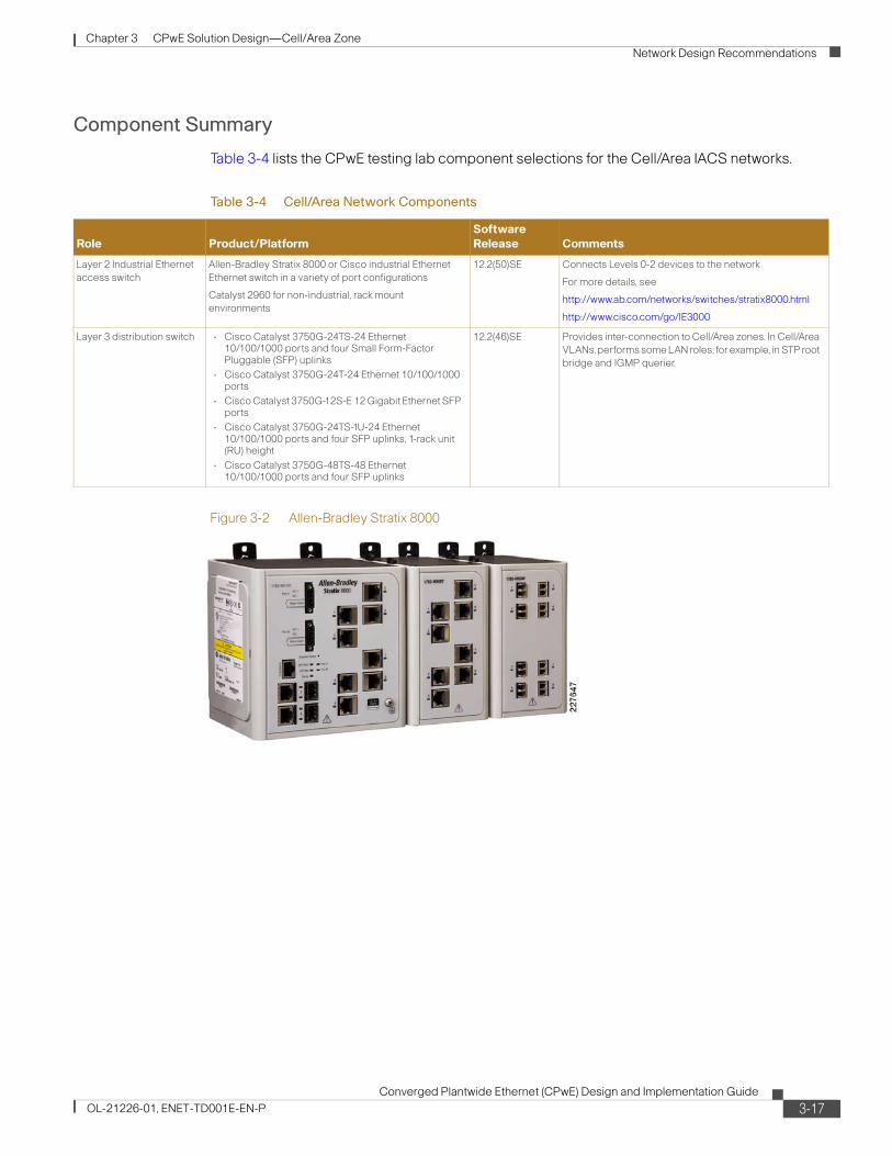
Chapter 3 CPwE Solution Design—Cell/Area Zone Network Design Recommendations
Component Summary
Table 3-4 lists the CPwE testing lab component selections for the Cell/Area IACS networks.
Figure 3-2 Allen-Bradley Stratix 8000
Table 3-4 Cell/Area Network Components
Role Product/PlatformSoftware Release Comments
Layer 2 Industrial Ethernet access switch
Allen-Bradley Stratix 8000 or Cisco industrial Ethernet Ethernet switch in a variety of port configurations
Catalyst 2960 for non-industrial, rack mount environments
12.2(50)SE Connects Levels 0-2 devices to the network
For more details, see
http://www.ab.com/networks/switches/stratix8000.html
http://www.cisco.com/go/IE3000
Layer 3 distribution switch • Cisco Catalyst 3750G-24TS-24 Ethernet 10/100/1000 ports and four Small Form-Factor Pluggable (SFP) uplinks
• Cisco Catalyst 3750G-24T-24 Ethernet 10/100/1000 ports
• Cisco Catalyst 3750G-12S-E 12 Gigabit Ethernet SFP ports
• Cisco Catalyst 3750G-24TS-1U-24 Ethernet 10/100/1000 ports and four SFP uplinks, 1-rack unit (RU) height
• Cisco Catalyst 3750G-48TS-48 Ethernet 10/100/1000 ports and four SFP uplinks
12.2(46)SE Provides inter-connection to Cell/Area zones. In Cell/Area VLANs, performs some LAN roles; for example, in STP root bridge and IGMP querier.
3-17Converged Plantwide Ethernet (CPwE) Design and Implementation Guide
OL-21226-01, ENET-TD001E-EN-P

Chapter 3 CPwE Solution Design—Cell/Area Zone Network Design Recommendations
Figure 3-3 Cisco IE 3000
If environmental requirements allow commercial grade switches, such as in a IACS control room, the key alternative to the industrial Ethernet switch is the Catalyst 2960 (for details, refer to the following URL: http://www.cisco.com/en/US/products/ps6406/index.html).
Figure 3-4 shows the Cisco Catalyst 3750.
Figure 3-4 Cisco Catalyst 3750
The Catalyst 3750 Layer-3 switch was chosen rather than the Catalyst 4500 switch for the following considerations:
• Lower cost
• StackWise feature comparable scalability and redundancy
• Already deployed at a large number of manufacturers
The StackWise feature is especially valuable because it:
• Allows for switches to be added and removed without affecting performance. Up to nine separate switches can be joined together.
• Easy to use availability features: the switch acts as one device, yet if any switch in the stack fails, the stack continues to operate without setup and configuration of specific protocols (e.g., HSRP).
3-18Converged Plantwide Ethernet (CPwE) Design and Implementation Guide
OL-21226-01, ENET-TD001E-EN-P
Chapter 3 CPwE Solution Design—Cell/Area Zone Network Design Recommendations
A chassis-based switch such as the Catalyst 4500 or Catalyst 6500 may be ideal in the following situations:
• Capacity or scalability is a concern; for example, when integrating a large number of Cell/Area IACS networks.
• Upgradeable processor and interfaces for longer-term viability.
• Better failover features for availability; for example, in-service upgradeability.
• When service modules (such as firewall and application delivery) are required.
The IACS network components used in this phase of the CPwE solution architecture are connected via single connections to the network infrastructure. This is common for IACS network devices applying the CIP protocol. Some controllers may support more than one Ethernet connection; multiple connections are supported for the purpose of scalability, segmentation, developing a linear topology or controller availability. These multiple connection applications for Cell/Area IACS network devices are not considered in this release of the CPwE solution architecture at this time.
Traffic FlowsTraffic flow in a Cell/Area IACS network is largely determined by the design and implementation of the IACS. These systems produce very different traffic patterns than the client-server and Internet-based applications in the IT domain or enterprise network. For example, 80 to 90 percent of the Cell/Area traffic is local as compared to a typical IT LAN in which perhaps less than 10 percent of the traffic is local. This is primarily driven by the cyclical I/O data being communicated on very short intervals (milliseconds) from devices to controllers and workstations/HMIs all on the same LAN or VLAN.
A network infrastructure should be designed to support the proper traffic flows. Features such as network segmentation can impact the network traffic flows and network performance.
Key considerations when designing traffic flows include the following:
• EtherNet/IP implementations have traditionally been unable to route multicast traffic since the time-to-live field in the IP packet is set to 1. Although updated CIP EtherNet/IP specifications (CIP Specifications version 1.3, Volume 2 EtherNet/IP Adaptation of CIP, December 2006) call for this limit to be removed, this DIG (DIG) is based on the implementation of TTL=1, because the routing of multicast traffic requires a more complex set of protocols and considerations to be applied.
The use of multicast for Implicit CIP I/O traffic is an application choice. The most recent version of the Rockwell Automation PAC configuration application (RSLogix 5000) version 18 and later, supports the choice of unicast or multicast delivery for certain types of Implicit I/O data. Explicit messaging data has always been unicast delivery via TCP. This CPwE DIG is based on multicast delivery. Devices and controllers configured for multicast delivery need to be located within the same Cell/Area IACS network as these packets cannot be routed, meaning that any router will drop the packet before forwarding it outside of the subnet/VLAN. Devices and controllers configured for unicast delivery, Implicit I/O or Explicit messaging, do not need to be within the same Cell/Area zone as that communication is routable.
Note Cisco and Rockwell Automation recommend that network developers design smaller Cell/Area IACS networks using multicast delivery and to route unicast delivery between Cell/Area zones for controller-to-controller information exchange and interlocking.
3-19Converged Plantwide Ethernet (CPwE) Design and Implementation Guide
OL-21226-01, ENET-TD001E-EN-P

Chapter 3 CPwE Solution Design—Cell/Area Zone Network Design Recommendations
• Traffic generated by the various network protocols (ARP, SNMP, RSTP, and IGMP) should also be considered. Properly configured, this is a minimal amount of the overall traffic. In an IT network, this is referred to as control traffic.
Figure 3-5 shows different Cell/Area zone traffic flows.
Figure 3-5 Cell/Area Zone Traffic Flows
Table 3-5 describes the traffic flows shown in Figure 3-5.
2276
49
Plant DMZFirewall (ASAs)
Engineering Laptop(RSLogix 5000) Network
Management
Manufacturing Zone
DMZ
Catalyst 3750Stackwise Switches
VFD DIO
Controller
Cell/Area Zone
IE Switch
VFD DIO
Controller
Cell/Area Zone
IE Switch
1c
7, 8
4b
5
1a
3
4a1b
26
CIP Explicit Traffic – e.g. HMI or Non-CIP Traffic
CIP Implicit Traffic – e.g. I/O
3-20Converged Plantwide Ethernet (CPwE) Design and Implementation Guide
OL-21226-01, ENET-TD001E-EN-P

Chapter 3 CPwE Solution Design—Cell/Area Zone Network Design Recommendations
Topology Options and Media ConsiderationsA large variety of Cell/Area IACS network topologies must be considered to address a wide range of industrial applications. This CPwE DIG considers the redundant star, ring, and linear/star topologies.
Topology starts with considering how devices are connected to the Cell/Area IACS network. In many industrial applications, the IACS devices themselves support only single network connections, and therefore are connected via only a single connection to a single access switch. Where availability is critical and the devices support multiple connections, they should be connected to multiple switches to avoid single points of failure. In those cases, the network infrastructure should be configured in such a way to support the resiliency/redundancy of the overall manufacturing process.
• Key considerations include the following:
• Physical layout—The layout of the manufacturing environment is a key driver of topology design. For example, a long conveyor belt system does not easily lend itself to a redundant star configuration, but rather a linear or ring topology.
Table 3-5 Cell/Area Zone Traffic Flowsch3_CPwE
Refer Number in Figure
From To Description Protocol Type Port
1 a,b,c Producer (for example, VFD Drive)
Consumer (for example, controller)
A producer (for example, VFD Drive, or controller) communicates data via CIP Implicit I/O (UDP multicast) traffic to multiple consumers
a—Represents device to controller IO
b—Represents controller–controller I/O
c—Represents controller reporting real-time status to HMI
EtherNet/IP UDP 2222
2 Producer Consumer Producers can communicate data via CIP I/O as UDP unicast traffic to a consumer.
EtherNet/IP UDP 2222
3 Consumer Producer Consumer (for example, controller or HMI) responds with output data or a heartbeat via CIP I/O (UDP unicast) traffic to the producer.
EtherNet/IP UDP 2222
4a, b Device Device CIP diagnostic, configuration, information, uploads/downloads, and identification data. For example, an HMI wants to open a CIP-connection with a controller. The CIP-connection request is communicated via TCP. Not shown, but the controller responds with a TCP message.
a—HMI opens a CIP connection for application monitoring
b—Engineering workstation downloads a program
EtherNet/IP TCP/UDP 44818
5 Device Workstation/laptop
Most EtherNet/IP devices can provide diagnostic and monitoring information via web browsers (HTTP)
HTTP TCP 80
6 Device DHCP/BootP server
Clients at startup for IP address allocation, not recommended for IACS network devices
DHCP/
BootP
UDP 67-88
7 Controller Mail server Mail messages as warnings or for informational status, within Manufacturing zone
SMTP TCP 25
8 Device Network manager
All network infrastructure (for example, switches and routers) and many Ethernet devices can send SNMP messages
SNMP UDP 161
3-21Converged Plantwide Ethernet (CPwE) Design and Implementation Guide
OL-21226-01, ENET-TD001E-EN-P

Chapter 3 CPwE Solution Design—Cell/Area Zone Network Design Recommendations
• Availability—Cisco and Rockwell Automation recommend using resilient network topologies (for example, redundant star and ring) over non-redundant topologies. These allow the network to continue to function after an event such as connection loss or switch failure. Although some of these events may still lead to downtime of the IACS, a resilient network topology may reduce that chance and should improve the recovery time.
• Real-time communications—Latency and jitter are impacted by a large variety of factors, but primary by the amount of traffic and number of hops a packet must make to reach its destination. The amount of traffic in a Layer-2 network is driven by various factors, but the number of nodes is important. Key guidelines include the following:
– Amount of latency introduced per switch.
– Bandwidth should not consistently exceed 50 percent of the interface capacity on any switch.
– Switch CPU should not consistently exceed 50 to 70 percent utilization. Above this level, the chances increase significantly that the switch may not properly process control packets and start behaving abnormally.
The key connectivity considerations assumed for CPwE design recommendations include the following:
• Redundant network connections to the end-device were not considered for this phase of CPwE. Redundant connections may be used in certain industries and applications; mostly process-related industries applied to critical infrastructure.
• Industrial Ethernet access switches are connected to a distribution switch for connectivity with the Manufacturing zone applications. Dual-homed or physically separate networks were not considered as they limit convergence (see the “Logical Segmentation and VLANs” section on page 3-32 for more information)
Part of the validation phase is to generate guidelines for the size of a Cell/Area IACS network and the limits of determinism that can be achieved as the Cell/Area IACS network increases. The Cell/Area IACS network in the test environment contains up to 16 switches, in the configurations shown in the following subsections.
Access and Uplinks
An important concept to establish is the type of links used to interconnect IACS end-devices, servers, switches, and routers. This is important because they describe their key purpose and the basic functions and features that the network infrastructure will apply to the inbound and outbound traffic on that port. This CPwE solution will describe essentially three types of ports and two types of Layer 2 connections. For example, Layer 2 ports are ports on which the switch or router will direct the incoming traffic based upon the Layer-2 MAC address in the Ethernet (Layer 2) header. For Layer 3 ports (or connections), the switch or router will direct the incoming packets based upon the IP Address in the IP (Layer 3) header. Note that a Layer 3-capable switch is required to support Layer 3 ports. This document did not test or include Layer-3 industrial Ethernet switches. Layer 3 ports are discussed in more detail in Chapter 4, “CPwE Solution Design—Manufacturing and Demilitarized Zones.” For the Cell/Area zone, there are essentially two key type of ports applied:
1. Layer-2 access ports used to connect end-devices, including all IACS end-devices.
2. Layer-2 trunk or uplink ports used to interconnect Layer-2 switches and carry traffic from multiple VLANs.
3-22Converged Plantwide Ethernet (CPwE) Design and Implementation Guide
OL-21226-01, ENET-TD001E-EN-P

Chapter 3 CPwE Solution Design—Cell/Area Zone Network Design Recommendations
Layer-2 access ports typically are termination points for the network as only one non-switching/routing device (MAC-address) is communicating on the connection. Based on this characteristic, a number of key considerations for Layer-2 access ports include the following:
• The switch assigns the port to a VLAN and tags all traffic from that port to that VLAN (see the “Logical Segmentation and VLANs” section on page 3-32 for more information).
• Turn-off aspects of the network resiliency protocol but maintain loop protection settings (see “Availability and Network Resiliency” section on page 3-41 for more information).
• Apply a QoS service policy to the port. Configure the port to trust or not trust the QoS markings on traffic entering the port (see “Quality-of-Service (QoS)” section on page 3-63).
• Apply port security and thresholds based on expected traffic patterns from IACS devices (see “Security” section on page 3-8).
Uplink or trunk ports are the inter-switch connections. Key considerations for Layer-2 trunk or uplink ports include the following:
• Use higher bandwidth ports, such as Gigabit Ethernet, since the connection caries traffic from multiple end-devices. This will help avoid congestion and bottlenecks.
• The switch assigns the port as a VLAN trunk port so it can handle packets for multiple VLANs (see the “Logical Segmentation and VLANs” section on page 3-32 for more information).
• Apply resiliency protocol to the port to manage multi-path connections between the switches that make up the network (see the “Availability and Network Resiliency” section on page 3-41 for more information).
• Apply a QoS policy and trust the QoS markings on traffic entering the port. Other switches on the network are executed to properly mark the traffic (see the “Quality-of-Service (QoS)” section on page 3-63).
• Port security and thresholds for trunk ports are not typically applied, although the VLAN, resiliency and QoS settings have some security consideration (see the relevant sections listed above).
These considerations are described in more detail in the following subsections. These considerations are also reflected in the Smartports macros that are features of the Cisco and Rockwell Automation industrial Ethernet switches. Smartports allow implementers to easily apply these concepts to the industrial Ethernet switches by following the implementation steps described in Chapter 5, “Implementing and Configuring the Cell/Area Zone.” It is important to note that these Smartport macros apply different QoS settings depending if the port or uplink is intended for IACS traffic. For example, an IP telephone has different settings than an IACS device. As well, different QoS settings are used for IACS networks than for standard IT networks.
Linear Topology
In a linear topology, the switches are connected to each other to form a chain of switches. Key characteristics include the following:
• The connection between the Layer-3 switch and the first Layer-2 switch is a natural bottleneck and more susceptible to oversubscription, which can degrade network performance.
• Simple, easy-to-implement configuration.
• Minimal amount of cabling required.
• No resiliency to loss of a connection.
• High level of flexibility for plant floor layout.
3-23Converged Plantwide Ethernet (CPwE) Design and Implementation Guide
OL-21226-01, ENET-TD001E-EN-P
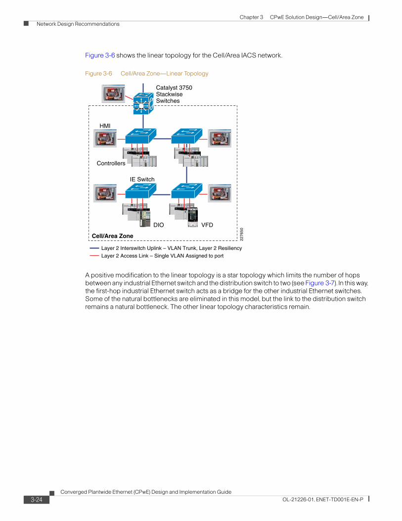
Chapter 3 CPwE Solution Design—Cell/Area Zone Network Design Recommendations
Figure 3-6 shows the linear topology for the Cell/Area IACS network.
Figure 3-6 Cell/Area Zone—Linear Topology
A positive modification to the linear topology is a star topology which limits the number of hops between any industrial Ethernet switch and the distribution switch to two (see Figure 3-7). In this way, the first-hop industrial Ethernet switch acts as a bridge for the other industrial Ethernet switches. Some of the natural bottlenecks are eliminated in this model, but the link to the distribution switch remains a natural bottleneck. The other linear topology characteristics remain.
2276
50Cell/Area Zone
Catalyst 3750StackwiseSwitches
HMI
VFDDIO
Controllers
IE Switch
Layer 2 Access Link – Single VLAN Assigned to port
Layer 2 Interswitch Uplink – VLAN Trunk, Layer 2 Resiliency
3-24Converged Plantwide Ethernet (CPwE) Design and Implementation Guide
OL-21226-01, ENET-TD001E-EN-P

Chapter 3 CPwE Solution Design—Cell/Area Zone Network Design Recommendations
Figure 3-7 Cell/Area Zone—Star Topology
Ring Topology
A ring topology is similar to a linear topology except that the last switch in the chain is connected to the Layer-3 switch, which forms a network ring. In a ring, if a connection is lost, each switch maintains connectivity to the other switches. Key considerations of the ring topology include the following:
• Additional cable connection to close the loop.
• Minimal level of network resiliency in that the network can recover from the loss of a single connection.
• More difficult to implement because it requires a resiliency protocol such as Rapid Spanning Tree.
• High level of flexibility for the plant floor layout.
• Although better than the linear, the top of the ring (connections to the Layer-3 switches) can become a bottleneck and is susceptible to oversubscription, which can degrade network performance. See the “Scalability” section on page 3-16 for information on the system and network latency impact the number of hops has on the IACS application.
Figure 3-8 shows the ring topology for the Cell/Area IACS network.
2276
51
Cell/Area Zone
Catalyst 3750StackwiseSwitches
HMI
VFDDIO
Controllers
IE Switch
Layer 2 Access Link – Single VLAN Assigned to port
Layer 2 Interswitch Uplink – VLAN Trunk, Layer 2 Resiliency
3-25Converged Plantwide Ethernet (CPwE) Design and Implementation Guide
OL-21226-01, ENET-TD001E-EN-P

Chapter 3 CPwE Solution Design—Cell/Area Zone Network Design Recommendations
Figure 3-8 Cell/Area Zone—Ring Topology
Redundant Star Topology
A redundant star topology is essentially where every Layer-2 access switch has dual-connections to a Layer-3 distribution switch. IACS devices are connected to the Layer-2 switches. This topology has the following advantages:
• Always only two hops from another Layer-2 switch.
• No natural bottlenecks in the Layer-2 network, because each switch has dual-connections to the Layer-3 devices.
• Each access switch can lose a single uplink connection and the network will continue to operate.
• Layer-2 network is maintained even if multiple connections are lost.
• Most complex cabling infrastructure required to establish dual-connectivity of each switch to the Layer-3 switch.
Figure 3-9 shows the redundant star topology for the Cell/Area IACS network.
2276
52
Catalyst 3750StackwiseSwitches
HMI
VFDDIO
Controllers
Cell/Area Zone
IE Switch
Layer 2 Access Link – Single VLAN Assigned to port
Layer 2 Interswitch Uplink – VLAN Trunk, Layer 2 Resiliency
3-26Converged Plantwide Ethernet (CPwE) Design and Implementation Guide
OL-21226-01, ENET-TD001E-EN-P
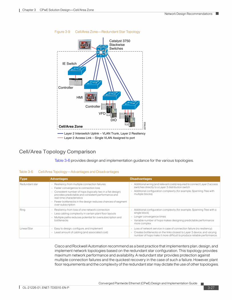
Chapter 3 CPwE Solution Design—Cell/Area Zone Network Design Recommendations
Figure 3-9 Cell/Area Zone—Redundant Star Topology
Cell/Area Topology Comparison
Table 3-6 provides design and implementation guidance for the various topologies.
Cisco and Rockwell Automation recommend as a best practice that implementers plan, design, and implement network topologies based on the redundant star configuration. This topology provides maximum network performance and availability. A redundant star provides protection against multiple connection failures and the quickest recovery in the case of such a failure. However, plant floor requirements and the complexity of the redundant star may dictate the use of other topologies.
Cell/Area Zone
Catalyst 3750StackwiseSwitches
HMI
VFD
DIO
Controller
Controller
IE Switch
2276
53
Layer 2 Access Link – Single VLAN Assigned to port
Layer 2 Interswitch Uplink – VLAN Trunk, Layer 2 Resiliency
Table 3-6 Cell/Area Topology—Advantages and Disadvantages
Type Advantages Disadvantages
Redundant star • Resiliency from multiple connection failures• Faster convergence to connection loss• Consistent number of hops (typically two in a flat design)
provides predictable and consistent performance and real-time characteristics
• Fewer bottlenecks in the design reduces chances of segment over-subscription
• Additional wiring (and relevant costs) required to connect Layer 2 access switches directly to a Layer 3 distribution switch
• Additional configuration complexity (for example, Spanning Tree with multiple blocks)
Ring • Resiliency from loss of one network connection• Less cabling complexity in certain plant floor layouts• Multiple paths reduces potential for oversubscription and
bottlenecks
• Additional configuration complexity (for example, Spanning Tree with a single block)
• Longer convergence times • Variable number of hops makes designing predictable performance
more complex
Linear/Star • Easy to design, configure, and implement• Least amount of cabling (and associated cost)
• Loss of network service in case of connection failure (no resiliency)• Creates bottlenecks on the links closest to Layer 3 device, and varying
number of hops make it more difficult to produce reliable performance.
3-27Converged Plantwide Ethernet (CPwE) Design and Implementation Guide
OL-21226-01, ENET-TD001E-EN-P

Chapter 3 CPwE Solution Design—Cell/Area Zone Network Design Recommendations
Resiliency and topology design decisions work together to meet availability requirements. (For details about resiliency, see the “Availability and Network Resiliency” section on page 3-41.)
Cisco and Rockwell Automation conducted multiple tests to evaluate the impact on network convergence by use of various topologies, resiliency protocols, and physical media. Table 7 shows the list of key test suites. For each test suite, a range of IACS devices was simulated. Each test had a baseline set of actual IACS devices in operation and producing a basic amount of IACS network traffic. To this environment, a traffic generator simulated more IACS devices (i.e., MAC addresses) on the network (for example, 200 and 400 MAC addresses), produced generic network traffic and measured the network convergence. To properly understand the test approach, terminology, and results, refer to Chapter 7, “Testing the CPwE Solution.”
Figure 3-10 shows resiliency of ring versus redundant star topologies with the same number of devices, switches, resiliency protocol, and amount of traffic. The test suites based on a ring topologies with copper and fiber uplinks (RMC8 and RMF8) have more variability and higher network convergence times than the test suites based on a redundant star with cooper and fiber uplinks (SMC8 and SMF8) for the range of MAC addresses tested across the range of number of end-devices simulated. Each test suite applied MSTP as the network resiliency protocol. This supports our recommendation that redundant star topologies converge faster and provide more consistent performance than ring topologies using MSTP. Test suite applying Flex Links had an even quicker convergence for redundant star topologies.
Table 7 CPwE Resiliency Test Suite
Test Suite Topology Resiliency Protocol Uplink Physical layer# of Industrial Ethernet switches
RMC8 Ring MSTP Copper 8
RMC16 Ring MSTP Copper 16
RPC8 Ring Rapid-PVST+ Copper 8
RMF8 Ring MSTP Fiber 8
SMC8 Redundant Star MSTP Copper 8
SMF8 Redundant Star MSTP Fiber 8
SEC8 Redundant Star EtherChannel Copper 8
SEF8 Redundant Star EtherChannel Fiber 8
SFC8 Redundant Star Flex Links Copper 8
SFF8 Redundant Star Flex Links Fiber 8
3-28Converged Plantwide Ethernet (CPwE) Design and Implementation Guide
OL-21226-01, ENET-TD001E-EN-P

Chapter 3 CPwE Solution Design—Cell/Area Zone Network Design Recommendations
Figure 3-10 Ring versus Redundant Star topologies
To summarize the topology recommendations, Table 8 identifies some key concerns/requirements from a implementers perspective and which topology would best address those concerns. The table provides information to help decide which topology is appropriate based on IACS requirements. The Cisco and Rockwell Automation test results show that a redundant star topology converges more quickly and more predictably than a similar sized and cabled ring infrastructure. This is a key factor in the overall recommendation of topologies.
Media Considerations
This CPwE DIG has not focused specifically on the physical media of an IACS network, as that is a highly specialized topic specific to the plant environment. However, Cisco and Rockwell Automation would like to include media considerations from a switching perspective.
Fiber Versus Copper Cabling
During resiliency testing, Cisco and Rockwell Automation noticed a significant difference in network convergence between topologies with fiber uplinks versus copper (all using the 1 Gb dual-use ports). This is due to the fact the IEEE specifies that a copper uplink can take up to 750 ms to detect link loss. Figure 3-11 depicts how the network convergence time, range, and variability improves with fiber versus copper; all other parameters are the same.
Table 8 Cell/Area Topology—Advantages and Disadvantages
Key Concerns Recommended Topology
• Highly available network with minimal convergence• High performance network with minimal bottlenecks• Straightforward network design
Redundant star
• Cabling complexity is a major concern• Highly available network • Cost
Ring
• Cost and simplicity over availability and performance Linear/Star
3-29Converged Plantwide Ethernet (CPwE) Design and Implementation Guide
OL-21226-01, ENET-TD001E-EN-P
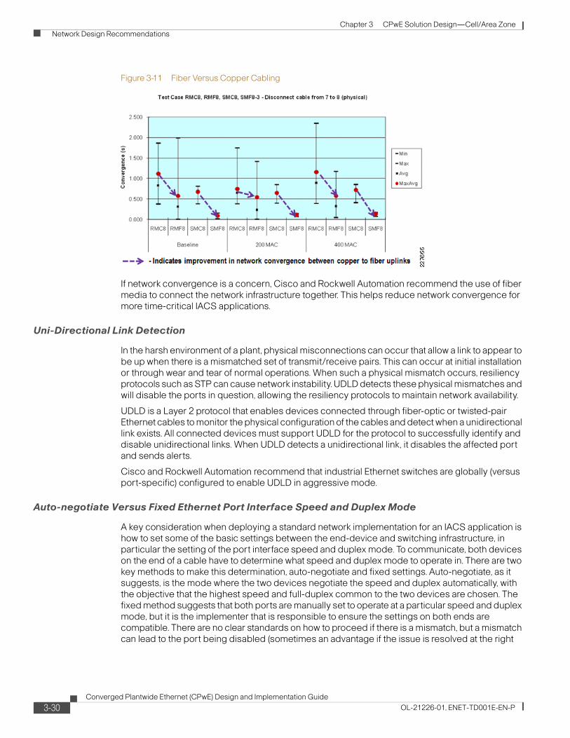
Chapter 3 CPwE Solution Design—Cell/Area Zone Network Design Recommendations
Figure 3-11 Fiber Versus Copper Cabling
If network convergence is a concern, Cisco and Rockwell Automation recommend the use of fiber media to connect the network infrastructure together. This helps reduce network convergence for more time-critical IACS applications.
Uni-Directional Link Detection
In the harsh environment of a plant, physical misconnections can occur that allow a link to appear to be up when there is a mismatched set of transmit/receive pairs. This can occur at initial installation or through wear and tear of normal operations. When such a physical mismatch occurs, resiliency protocols such as STP can cause network instability. UDLD detects these physical mismatches and will disable the ports in question, allowing the resiliency protocols to maintain network availability.
UDLD is a Layer 2 protocol that enables devices connected through fiber-optic or twisted-pair Ethernet cables to monitor the physical configuration of the cables and detect when a unidirectional link exists. All connected devices must support UDLD for the protocol to successfully identify and disable unidirectional links. When UDLD detects a unidirectional link, it disables the affected port and sends alerts.
Cisco and Rockwell Automation recommend that industrial Ethernet switches are globally (versus port-specific) configured to enable UDLD in aggressive mode.
Auto-negotiate Versus Fixed Ethernet Port Interface Speed and Duplex Mode
A key consideration when deploying a standard network implementation for an IACS application is how to set some of the basic settings between the end-device and switching infrastructure, in particular the setting of the port interface speed and duplex mode. To communicate, both devices on the end of a cable have to determine what speed and duplex mode to operate in. There are two key methods to make this determination, auto-negotiate and fixed settings. Auto-negotiate, as it suggests, is the mode where the two devices negotiate the speed and duplex automatically, with the objective that the highest speed and full-duplex common to the two devices are chosen. The fixed method suggests that both ports are manually set to operate at a particular speed and duplex mode, but it is the implementer that is responsible to ensure the settings on both ends are compatible. There are no clear standards on how to proceed if there is a mismatch, but a mismatch can lead to the port being disabled (sometimes an advantage if the issue is resolved at the right
3-30Converged Plantwide Ethernet (CPwE) Design and Implementation Guide
OL-21226-01, ENET-TD001E-EN-P

Chapter 3 CPwE Solution Design—Cell/Area Zone Network Design Recommendations
time) or operating in duplex mismatch, Devices operating in duplex mismatch may operate without error initially, but under increased load and traffic, intermittent issues may arise that are difficult to identify and resolve if not specifically monitored.
Both methods have pros and cons. Network developers need to choose the method that best supports their current environment and practices: green-field versus current installed base, end-device method support, the level of expertise and consistency of the personnel maintaining and configuring both the network and IACS devices. Cisco and Rockwell Automation do recommend the following considerations:
• Use full-duplex—This setting eliminates any issues with collisions between the end-device and the switch, and helps ensure packets are not lost between them.
• Be consistent—The best way to implement either method is consistency across the environment. Partial implementations tend to lead to more mismatches.
• Verification—In either method, Cisco and Rockwell Automation recommend that a process is put in place to validate the port settings and warn maintenance personnel when a port is operating in half-duplex, that there is a port setting mismatch or that auto-negotiation between the ports failed. Therefore, reducing the chances that the port settings become an issue while the IACS is in operations.
Here are some considerations for auto-negotiate and fixed settings:
• Auto-negotiate:
– Pro—Most new IACS devices and switch infrastructure (including the Cisco and Rockwell Automation industrial Ethernet switches) support and have auto-negotiate as the default setting for Ethernet ports.
– Pro—The auto-negotiate function requires the least amount of effort and knowledge to configure. Out of the box, most end-devices are configured to auto-negotiate, therefore requiring no configuration of these settings at time of replacement
– Pro—The auto-negotiate function includes the auto-MDIX feature which dynamically supports use of either cross-over or straight-through cabling, especially relevant for inter-switch communication.
– Con—Although rare, auto-negotiate can fail, and leave the port setting in low bandwidth or half-duplex. This is a situation that usually manifests itself in manufacturing, when traffic levels increase causing intermittent and hard to debug network problems.
– Con—Older legacy devices are in the environment have a higher tendency to either not support auto-negotiate or poorly support it, resulting in issues.
• Fixed:
– Pro—Once set, the devices will consistently operate at the configured speed and duplex.
– Con—Requires manual involvement at end-device implementation to set the fixed speed and duplex, requiring skilled time and effort
– Con—Fixed does not allow the use of auto-MDIX, which means that use of crossover cables for inter-switch communication is required for fixed deployments.
Network developers should choose upfront which method to apply in an IACS network. Fortunately, the industrial Ethernet switches, and especially the Stratix 8000, support configuration of the port settings and monitoring of port speed/duplex status. Therefore, regardless of the mechanism chosen, there are easy-to-use mechanisms to perform the required steps to implement and manage the port settings.
3-31Converged Plantwide Ethernet (CPwE) Design and Implementation Guide
OL-21226-01, ENET-TD001E-EN-P
Chapter 3 CPwE Solution Design—Cell/Area Zone Network Design Recommendations
Summary Topology and Media Recommendations
In summary, the key CPwE network topology and media recommendations are as follows:
1. If plant availability is a concern and network recovery from outages in seconds or less is required, use a topology that offers path redundancy: redundant star or ring.
2. The redundant star topology offer performance and resiliency advantages over the ring topology, but it is more complex and costly to implement due to the wiring requirements.
3. Use higher bandwidth ports (for example, 1 Gb/sec) for uplinks and inter-switch connectivity as they carry traffic from multiple devices.
4. If network resiliency is a key requirement, use of fiber uplinks versus copper is recommended for Layer 2 uplinks.
5. Switches should have UDLD globally enabled in aggressive mode.
6. All connections should use full-duplex communication; choose a mechanism to achieve that by applying either an auto-negotiate or fixed speed/duplex approach.
Logical Segmentation and VLANsLogical segmentation is the process of outlining which endpoints need to be in the same LAN. Segmentation is a key consideration for a Cell/Area IACS network. Segmentation is important to help manage the real-time communication properties of the network, and yet support the requirements as defined by the network traffic flows. Security is also an important consideration in making segmentation decisions. A security policy may call for limiting access of plant floor personnel (such as a vendor or contractor) to certain areas of the plant floor (such as a functional area). Segmenting these areas into distinct subnets and VLANs greatly assists in the application of these types of security considerations.
Subnets and VLANs are two concepts that go hand-in-hand. A VLAN is a broadcast domain within a switched network. Devices within a VLAN can communicate with each other without a Layer-3 switch or router. Devices in different VLANs need a Layer-3 switch or router to communicate the traffic. Subnets are simply a subset of IP addresses assigned to a set of devices. Subnets are Layer-3 (Network/IP) concepts and VLANs are Layer 2 (data-link/Ethernet). Typically, devices in a VLAN are assigned IP addresses from the same subnet and a subnet has devices in one VLAN to make routing easier and more straightforward. Best networking practice is where there is a one-to-one relationship between VLANs and subnets.
When designing IACS network logical segmentation plans, there are competing objectives. On one hand, all Level 0 to 2 devices that need to communicate multicast I/O between each other must be in the same LAN. It would seem easier to put all devices in one VLAN and subnet. However, on the other hand, the smaller the VLAN, the easier it is to manage and maintain real-time communications as the broadcast traffic and multicast traffic is constrained. Real-time communications are harder to maintain as the number of switches, devices, and the amount of network traffic increase in a LAN. Smaller VLANs also isolate devices from faulty or compromised devices that as those devices only impact the devices in their VLAN, and VLANs are the basis for setting and implementing security policy and protection. VLANs provide the broadcast isolation, policy implementation, and fault-isolation benefits that are required in highly available networks.
Note Cisco and Rockwell Automation recommend that network developers strive to design smaller LANs or VLANs, while recognizing that the traffic patterns of an IACS may make this difficult if routing is required.
3-32Converged Plantwide Ethernet (CPwE) Design and Implementation Guide
OL-21226-01, ENET-TD001E-EN-P

Chapter 3 CPwE Solution Design—Cell/Area Zone Network Design Recommendations
There are many approaches to segmenting a network. Manufacturing facility networks can be divided by functional sections of the plant floor (see 1 in Figure 3-12), product lines (see 2 in Figure 3-12), and traffic type (for example, I/O, controller-to-controller, and Explicit message traffic). To achieve the goal of minimizing VLAN sizes, a mixture of all three may be used.
Figure 3-12 Sample Plant Floor—Brewing and Bottling
Segmentation can be achieved via the following two key mechanisms in the Cell/Area IACS network:
• Physical—Use of separate cabling and Layer-2 access switches to achieve segmentation
• VLAN (802.1Q)—Use of the VLAN protocol to achieve a VLAN that can be implemented on the same physical infrastructure
Physical segmentation is a highly common approach in current Ethernet implementations, but has been applied to an extreme. For example, a common approach in current Ethernet deployments is to physically separate I/O traffic from HMI traffic and not to connect the I/O traffic to any interconnected Layer-3 distribution switch. In these cases, a controller has separate network interface connections (NIC) to each network, and the only means to communicate between the two networks is over the backplane of the controller. The I/O network is, therefore, reachable only via the controller backplane that processes only CIP traffic. (See Figure 3-13.)
Regular Brew
2209
80
Filling
Packaging
Office/Data Center
RawMaterial
FinishedGoods
1 2
Shipping
Dark Brew
Brewing
3-33Converged Plantwide Ethernet (CPwE) Design and Implementation Guide
OL-21226-01, ENET-TD001E-EN-P

Chapter 3 CPwE Solution Design—Cell/Area Zone Network Design Recommendations
Figure 3-13 Gateway Physical Segmentation Example—Two NICs for Network Segmentation
The effects of this include the following:
• Devices on the I/O network are not accessible via non-CIP protocols (such as SNMP or HTTP), limiting overall interconnectivity.
• A controller was not designed to route, switch or bridge continuous network traffic, and may introduce delays when used in this manner.
• Network-based services (such as security, management, IP address allocation, and so on) must either be replicated in each network or are not available.
• Increased costs occur because the available network resources in the HMI network (for example, open ports) are not available in I/O network.
Although physical segmentation dedicates network resources to these various traffic types and helps increase the level of certainty that the traffic receives sufficient network resources, Cisco and Rockwell Automation recommend that these networks be at least connected to Layer-2 or Layer-3 switches so as to enable interconnectivity via other methods than the controller. In this way, the networks stay interconnected and get the full benefits of the converged network. Additionally, Cisco and Rockwell Automation recommend consideration of other ways (for example, application of QoS) to ensure that critical network traffic (such as Implicit I/O) receives appropriate network performance. Even if physical segmentation is chosen, many of the design and implementation considerations here still apply (for example, security, availability, QoS, and multicast management) as the physically segmented network is still a Cell/Area or Layer 2 network.
Note Cisco and Rockwell Automation recommend the use of VLANs in addition to any physical segmentation, and that all Cell/Area LANs be connected to Layer-3 distribution switches to maintain connectivity.
In this case, where physical segmentation is a strong requirement, Figure 3-14 shows the recommended approach.
DIO
HMI
IE Switch
Controller
HMI Network
I/O Network
IE Switch
NIC
NIC
2276
56
3-34Converged Plantwide Ethernet (CPwE) Design and Implementation Guide
OL-21226-01, ENET-TD001E-EN-P

Chapter 3 CPwE Solution Design—Cell/Area Zone Network Design Recommendations
Figure 3-14 Recommended Physical Segmentation—Two NICs for Scalability
VLAN Overview
A VLAN is a logical broadcast domain that can span multiple physical LAN segments. You can design a VLAN structure that allows to group stations that are segmented logically by functions, line, and other plant floor characteristics without regard to the physical location of the devices. You can assign each end-device switch port to only one VLAN, thereby adding a layer of security. Ports in a VLAN share broadcasts; ports in different VLANs do not, although broadcasts can be directionally routed (needed for a data server such as RSLinx Classic). Containing broadcasts in a VLAN improves the overall performance of the network.
A VLAN is a switched network segmented on a functional, application, or organizational basis as opposed to a physical or geographical basis. Switches filter destination MAC addresses and forward VLAN frames only to ports that serve the VLAN to which the traffic belongs. A VLAN consists of several end systems, either hosts or network equipment (such as switches and routers), all of which are members of a single logical broadcast domain. A VLAN no longer has physical proximity constraints for the broadcast domain. This VLAN is supported on various pieces of network equipment (for example, LAN switches) that support VLAN trunking protocols between them. Managed switches support multiple VLANs, as depicted in Figure 3-15.
DIO
IE Switch
ControllerI/O and HMI Network
NIC
NIC
2276
57
HMI
3-35Converged Plantwide Ethernet (CPwE) Design and Implementation Guide
OL-21226-01, ENET-TD001E-EN-P

Chapter 3 CPwE Solution Design—Cell/Area Zone Network Design Recommendations
Figure 3-15 Single Switch supporting Multiple VLANs
A VLAN can span multiple switches as the topology shown in Figure 3-16, controller 1 is controlling the variable frequency drive 1 and distributed I/O 1 in VLAN 10; and controller 2 is controlling variable frequency drive 2 and distributed I/O 2 in VLAN 20. Non-IACS devices are connected to a separate VLAN, VLAN 100. But the devices are connected to a variety of switches. Without a router or Layer 3 switch, devices in VLAN 10 could not communicate with devices in VLAN 20 or VLAN 100.
VariableFrequency Drive
(VFD)
Phone
Cell/Area VLAN 10 EtherNet/IP Devices
Cell/Area VLAN 20 EtherNet/IP Devices
Engineer VLAN 100 Office Devices
Controller#1
Laptop
IP
HumanMachineInterface
(HMI)
Controller#2
Distributed I/O
2535
87
3-36Converged Plantwide Ethernet (CPwE) Design and Implementation Guide
OL-21226-01, ENET-TD001E-EN-P

Chapter 3 CPwE Solution Design—Cell/Area Zone Network Design Recommendations
Figure 3-16 VLAN Spanning Multiple Switches
VLANs offer the following features:
• Segmentation and broadcast control—Just as switches isolate collision domains for attached hosts and forward only appropriate traffic out a particular port, VLANs refine this concept further and provide complete isolation between VLANs. A VLAN is a bridging domain, and all broadcast and multicast traffic is contained within it.
• End-device performance—End-devices in an IACS tend to have limited ability to handle large amounts of network traffic. Implementation of VLANs, especially smaller VLANs, limits the amount of traffic an end-device receives and has to process. This frees up network resources and overall system resources (CPU, memory, etc.).
• Maintain the ability to interconnect VLANs with a Layer-3 capable switch or router to handle inter-Cell/Area zone communication.
• Security—VLANs provide security in two ways:
– High-security IACS devices can be grouped into a VLAN, possibly on the same physical segment, and no IACS devices outside of that VLAN can communicate with them.
– Because VLANs are logical groups that behave like physically separate entities, inter-VLAN communication is achieved through a router. When inter-VLAN communication occurs through a router, all the security and filtering functionality that routers traditionally provide can be used because routers are able to look at Layer 3 information. In the case of non-routable protocols, there can be no inter-VLAN communication. All communication must occur within the same VLAN.
Phone
Laptop
IP
Controller #1
Distributed I/O #1
Controller #2
Distributed I/O #2
VFD #1
VFD #2
VLAN 10
VLAN 20
VLAN 100
2535
88
Cell/Area VLAN 10 EtherNet/IP Devices
Cell/Area VLAN 20 EtherNet/IP Devices
Engineer VLAN 100 Office Devices
Inter-switch VLAN Trunk
3-37Converged Plantwide Ethernet (CPwE) Design and Implementation Guide
OL-21226-01, ENET-TD001E-EN-P

Chapter 3 CPwE Solution Design—Cell/Area Zone Network Design Recommendations
• Network Performance—The logical grouping of devices allows, for example, an engineer making intensive use of a networked CAD/CAM station or testing a multicast application to be assigned to a VLAN that contains just that engineer and the servers or devices he or she needs. The work of this engineer does not affect the rest of the engineering group, which results in improved performance for the engineer (by being on a dedicated LAN) and improved performance for the rest of the engineering group (whose communications are not slowed down by the single engineer using the network).
• Network management—The logical grouping of IACS devices, divorced from their physical or geographic locations, allows easier network management. It is no longer necessary to pull cables to move an IACS device from one network to another. Adds, moves, and changes are achieved by configuring a port into the appropriate VLAN. Expensive, time-consuming re-cabling to extend connectivity in a switched LAN environment is no longer necessary because network management can be used to logically assign an IACS device from one VLAN to another.
For more background information or VLANs, see the following:
• VLANs and VLAN trunking— http://www.cisco.com/en/US/partner/tech/tk389/tk689/tsd_technology_support_protocol_home.html
• LAN switching and VLANs— http://www.cisco.com/en/US/tech/tk1330/tsd_technology_support_technical_reference_chapter09186a008075983b.html
• Internetwork design guide–LAN switching— http://www.cisco.com/en/US/partner/tech/tk1330/technologies_design_guide_chapter09186a008066670e.html
• Designing Switched LAN internetworks— http://www.cisco.com/en/US/partner/docs/internetworking/design/guide/nd2012.html
Any end-device to be connected directly to multiple VLANs typically requires multiple network interface cards (NICs) available to the device. For example, controllers can have multiple NIC cards installed because of their modularity, and therefore have direct Layer-2 access to multiple VLANs. This may also be a consideration in the segmentation of the network. Note though, a Layer-3 switch or router can route packets between VLANs if the appropriate security allows for that. A device need not be on multiple VLANs to talk to devices on multiple VLANs.
VLAN Design
The key steps to design a VLAN approach include the following:
Step 1 Assign the various Cell/Area zones a VLAN that corresponds to an IP subnet in which the devices in that zone all have their IP address. For more on IP addressing, see Chapter 4, “CPwE Solution Design—Manufacturing and Demilitarized Zones.”
Step 2 Determine how to deploy the VLANs into the network infrastructure.
Step 3 Determine how to configure the VLAN Interface, end-device ports and switch uplinks.
Once the VLANs and IP addressing schema has been set, the next key design decision is how to deploy VLANs into the network infrastructure. Cisco and Rockwell Automation recommend that VLANs are manually configured on the switches. IACS networks tend to be designed and configured and not updated very often, if at all during their lifetime. There are “automated” ways to
3-38Converged Plantwide Ethernet (CPwE) Design and Implementation Guide
OL-21226-01, ENET-TD001E-EN-P

Chapter 3 CPwE Solution Design—Cell/Area Zone Network Design Recommendations
manage the VLANs in a switch, for example to exemplify the VLAN trunk protocol (VTP). But these mechanisms carry inherent risk as inadvertent changes could have significant impact to the IACS network. Therefore, Cisco and Rockwell Automation recommend that VTP is in transparent mode on the IACS network. Manual VLAN configuration requires a bit more work up front to implement the VLANs onto the network infrastructure, but once complete, it lowers this risk of operational issues due to inadvertent VTP updates.
Trunking
Trunks are also an important concept of deploying VLANs. The inter-switch connections in a Layer-2 network deploying VLANs are referred to and configured as trunks as they carry traffic for multiple VLANs. The relevant standard is IEEE 802.1Q, which specifies VLAN tagging to carry multiple VLANs on Ethernet links between switches. IEEE 802.1Q is the prevalent and most often used standard.
Cisco and Rockwell Automation recommend using IEEE 802.1Q for inter-switch connections within the Cell/Area zone. Some Cisco switches support another protocol, ISL, but that is a proprietary pre-cursor to 802.1Q and is not recommended.
As stated above, Cisco and Rockwell Automation recommend that manual configuration is used; therefore, the inter-switch connections are set to use 802.1Q and set negotiation to off to enforce use of 802.1Q.
VLAN1 and Native VLANs
Two important considerations in designing a VLAN network are the use of VLAN 1 and the native VLAN. The native VLAN is the VLAN to which a port returns when it is not trunking. Also, an IEEE 802.1Q trunk does not apply a VLAN tag to the native VLAN; in other words, the VLAN tag is implicit. The Native VLAN is the assigned VLAN for the port (and used if Trunking is removed) and is the VLAN used by network-specific protocols (for example, LACP, MSTP, or Resilient Ethernet Protocol). VLAN 1 is the default native VLAN on trunk ports on Cisco-based switches and therefore may used by a number of network infrastructure protocols. For a number of performance and security reasons (for example, VLAN hopping, for more on VLAN hopping see Chapter 7, “Testing the CPwE Solution.” Cisco and Rockwell Automation recommend the following in regards to VLAN 1 and native VLANs for trunk ports:
• Both sides of an inter-switch trunk must be configured with the same native VLAN.
• Configure the native VLAN to be a dedicated and specific VLAN not already in use: for example, IACS Cell/Area Zone VLAN. The Native VLAN should not be routed to/from and therefore is never enabled on the router or Layer 3 distribution switch. No IACS network traffic should flow in the Native VLAN.
• It is recommended that the size and scope of a Native VLAN be a Cell/Area zone . For example, on a Cell/Area zone, the same Native VLAN would reside on all the trunks between the switches.
• Configure the 802.1Q trunk to allow only specified VLANs. All other VLANs should be “pruned” from the trunk, including VLAN 1.
• Define IACS devices to use a specific VLAN other than the native VLAN and VLAN 1. Allow these VLANs on the trunks.
• Cisco and Rockwell Automation recommend to not use VLAN 1 for any purpose. Some security threats assume that VLAN 1 is the default VLAN for data and/or management traffic and may target VLAN 1 in their attacks.
3-39Converged Plantwide Ethernet (CPwE) Design and Implementation Guide
OL-21226-01, ENET-TD001E-EN-P
Chapter 3 CPwE Solution Design—Cell/Area Zone Network Design Recommendations
Management VLANs
Management VLANs are also an important consideration when establishing a VLAN concept. In the IT and enterprise network, management VLANs are common and used as a means to access the network and IT infrastructure separate from the data VLANs. If IT is involved in managing the IACS network, they may want to establish management VLANs. Essentially, a management VLAN is a VLAN on which only the network infrastructure has IP addresses. The concept can also be taken so far as to establish an out-of-band physical network with the network infrastructure so as to allow network connectivity even when the in-band network is disrupted. Given the cost of cabling and infrastructure, this is not a consideration for most manufacturers.
Management VLANs are a supported concept, especially when IT may be involved in IACS networking. If Cell/Area zone network management is to be performed by plant floor personnel, putting the switch in the IACS VLANs provides a management interface to the network infrastructure so IACS applications (for example, controller with RSLogix 5000) can access the network infrastructure for management, monitoring and control, the same reasons why a management VLAN is established.
VLAN Numbering
VLANs are identified by a number between 1 and 4094. VLANs 1002 to 1005 are for backwards compatibility with legacy Layer-2 network protocols and cannot be used. VLANs 1006 to 4094 are the extended range VLANs. These cannot be used in conjunction with the ISL trunking protocol or VTP in client-server mode, neither of which is recommended by Cisco or Rockwell Automation for use in VLAN management.
The section on Cell/Area zone implementation will cover in detail the implementation of VLANs, but the following is a quick summary of the recommendations:
• The Cell/Area zone VLANs must be defined on a distribution/core switch (Layer 3 capable), so the switch can route between VLANs.
• All CIP-bearing VLANs should have IP directed broadcast-enabled and CIP-enabled to allow connectivity to RSLinx data servers in the Manufacturing zone. This is applied to the outbound interface on the Layer-3 switch.
• For CIP integration, the industrial Ethernet switches must have a VLAN interface defined with a specific IP address on the Cell/Area zone VLANs where the switch must communicate with CIP enabled controllers. A switch can have IP addresses in multiple Cell/Area VLANs; however, only one VLAN can be CIP-enabled.
• Set the switch in VTP mode transparent (all switches) to reduce the potential for operational error.
• Consider establishing a management VLAN, especially if IT or IT tools will be involved in the Cell/Area zone network management.
Uplinks or inter-switch connections:
• Hard set the trunk mode to ON and the encapsulation negotiate to OFF for optimal network convergence.
• On all trunk ports in switches in a Cell/Area zone, assign the native VLAN to an unused ID to avoid VLAN hopping. The native VLAN setting has to be the same on both sides of the trunk.
• Set the trunk encapsulation to dot1q.
• Manually prune all VLANs except those that are needed.
Configure the end-host ports:
3-40Converged Plantwide Ethernet (CPwE) Design and Implementation Guide
OL-21226-01, ENET-TD001E-EN-P

Chapter 3 CPwE Solution Design—Cell/Area Zone Network Design Recommendations
• Use switchport mode host command to set the port for an access device.
• The end-device must be assigned an IP address, subnet mask, and default gateway in the appropriate subnet.
• Configure the interface for the appropriate VLAN.
For more information on VTP, refer to the following URL: http://www.cisco.com/en/US/partner/tech/tk389/tk689/technologies_tech_note09186a0080094c52.shtml#vtp_modes
For more information on VLAN best practices, refer to the following URL: http://www.cisco.com/en/US/partner/products/hw/switches/ps700/products_white_paper09186a00801b49a4.shtml#cg1
Key Segmentation and VLAN Recommendations
The following are logical segmentation and VLAN recommendations for CPwE:
• Segment the IACS network into Cell/Area zones, where each zone is a subset of devices that communicate consistently with each other. All devices should have an IP address in the same IP subnet and be in the same VLAN. Smaller Cell/Area zones are in general better.
• All devices communicating with each other via multicast (I/O) traffic must be in the same VLAN
• Layer-3 switches or routers are required to route traffic between VLANs, which may impact traffic flow.
• Each VLAN should consist of a single IP subnet.
• If non-manufacturing traffic (PC and so on) must exist in the physical topology, it should be on a separate VLAN.
• Configure VTP mode as transparent to avoid operational error because very few VLANs are used.
• Assign all end-device or host ports a VLAN and set to switchport mode access.
• Do not explicitly use VLAN 1 as it is easily misused and can cause unexpected risks (see the “Security” section on page 3-8).
• All uplinks are connected as 802.1Q trunks.
• Use an unused VLAN as the native VLAN on all trunk ports.
• Prune all unused VLANs from a trunk.
Availability and Network ResiliencyThere are a number of factors that influence the availability of the network including network design, component selection, and redundancy. This section focuses on the use of network resiliency protocols to allow multiple diverse paths in the network. These protocols allow multiple paths in the network while preventing network loops. Previously highlighted recommendations that are important to availability are as follows:
• Use a network topology that offers redundant uplink paths to allow the network to quickly recover from an uplink failure.
• Use redundant network hardware for key network functions, such as the distribution switch. Cisco and Rockwell Automation testing and much of the CPwE recommendations here assume stacked, redundant distribution switches.
3-41Converged Plantwide Ethernet (CPwE) Design and Implementation Guide
OL-21226-01, ENET-TD001E-EN-P

Chapter 3 CPwE Solution Design—Cell/Area Zone Network Design Recommendations
Use fiber media in the uplinks for faster link-down notification (see the “Fiber Versus Copper Cabling” section on page 3-29). Depending on the topology selected, various availability options can be designed into the network. If a topology is chosen with resiliency (for example, redundant star or ring), some form of network resiliency protocol is required to manage loops in the network. Loops are created when Layer-2 network devices are connected with multiple paths to reach the same destination. If left unmanaged, loops can cause serious network issues by creating broadcasts storms (messages continuously passed around the network) that quickly disrupt network service. Both standard and proprietary protocols have been developed to manage the loops and to react to connection losses by blocking and unblocking redundant links.
The protocols identify (either manually or automatically) one or more connections to be virtually turned off to eliminate loops. When a connection is lost, the protocols must recognize the disruption and reactivate a blocked connection to restore network viability. The network convergence time is a measure of how long it takes to detect a fault, find an alternate path, and recover from the fault. During the network convergence time, some portion of the traffic is dropped by the network because interconnectivity does not exist. If the convergence time is longer than the cycle time in the IACS, the systems on the affected portion of the network may stop operating and bring parts of the plant floor to a halt. Plant floor personnel and Control Engineers may decide that the additional cost of a resilient network does not provide sufficient value if the network convergence time exceeds the cycle time. Although network convergence may not be fast enough to ensure IACS uptime, Cisco and Rockwell Automation recommend the use of resilient network topologies because they allow the manufacturing operations to continue when IACS are restarted without waiting on lost connections to be restored.
Note Although network convergence may not be fast enough to ensure IACS uptime, Cisco and Rockwell Automation recommend the use of resilient network topologies because they allow the manufacturing operations to continue when IACS are restarted without waiting on lost connections to be restored.
There are standard and proprietary protocols to manage resilient network topologies. The standard protocols are based on STP, which implements the 802.1D IEEE algorithm by exchanging Bridge Protocol Data Unit (BPDU) messages with other switches to detect loops, and then removes the loop by shutting down selected bridge interfaces. This algorithm guarantees that there is only one active path between two network devices. RSTP, based on IEEE 802.1w, is an evolution of the STP 802.1D standard and provides for faster Spanning Tree convergence after a topology change. The standard also includes features equivalent to Cisco PortFast, UplinkFast, and BackboneFast for faster network convergence.
For standard resilient network technologies within a multi-vendor environment, Cisco and Rockwell Automation recommend using MSTP as the resiliency protocol. For more information, refer to the following URL:
http://www.cisco.com/en/US/partner/tech/tk389/tk621/tsd_technology_support_protocol_home.html
Resiliency Protocol overview
This section briefly provides an overview of the key resiliency protocols covered in the scope of this CPwE DIG. The overview provides a brief background on protocol (e.g., versions), an abbreviated description of how the protocol operates and a description of the key benefits of the protocol.
3-42Converged Plantwide Ethernet (CPwE) Design and Implementation Guide
OL-21226-01, ENET-TD001E-EN-P

Chapter 3 CPwE Solution Design—Cell/Area Zone Network Design Recommendations
Spanning Tree Protocol (STP)
Spanning Tree Protocol (STP) is a Layer-2 protocol designed to run on bridges and switches. Its main purpose is to ensure that loops are avoided when there are redundant paths by deterministically blocking appropriate interfaces. If a link failure occurs in such a network, the STP is responsible for establishing a new path for data traffic.
Spanning Tree is arguably the only standard network protocol commonly available from a wide-range of vendors and across any type of topology. It is a reasonable expectation that products from two or more network infrastructure vendors would interoperate when running STP. Cisco and Rockwell Automation know of no tests to verify the interoperability of STP between vendors.
Spanning Tree is an IEEE standard. This IEEE standard has gone through several revisions since its conception which are summarized as follows:
1. Original Spanning Tree incorporated into IEEE 802.1D. STP will recover from a topology change in less than 60 seconds. Generally speaking, STP is too slow to use in IACS networks.
2. Rapid Spanning Tree known as IEEE 802.1w now incorporated into IEEE 802.1D- 2004, which significantly reduced the convergence time.
3. Multiple Spanning Tree known as IEEE 802.1s now incorporated into IEEE 802.1Q-2003 extends the RSTP to work with multiple VLANs.
The standards are backward compatible with each other, but may lose some of the performance advantages. For example, a ring of switches operating with both STP and RSTP, will default to using STP and thereby lose the performance advantages of RSTP. We recommend that when using Spanning Tree, the switches in a topology are all operating the same STP protocol.
Key advantages of Spanning Tree include the following:
• Plug-and-play, STP sends packets to determine whether loops exist in the topology. If a loop is inadvertently created and STP has not been disabled, it will detect the loop and will block a port to “close” the loop. For this feature in particular, Cisco and Rockwell Automation recommend that STP be on in a topology unless there are specific conflicts. These may mean STP is running, but not actively detecting a loop and thereby not the active resiliency protocol.
• Consistent, in the sense that on the same topology, STP will always choose the same link to block
• Supports a wide-variety of topologies. Spanning Tree will function on any redundant topology.
• Standard—Since STP is defined in various IEEE standards, infrastructure from various vendors can be configured in a topology and interoperate. This CPwE solution did not test network infrastructure from various vendors and recommends that if such a topology were to be used, that the configuration be sufficiently tested.
Key disadvantages of Spanning Tree include the following:
• Of the protocols tested, Spanning Tree and Rapid Spanning Tree converge more slowly than other protocols. Cisco and Rockwell Automation did not find that rapid Spanning Tree converges fast enough to avoid application outages on a consistent basis to recommend it for other than information/process applications.
• Original STP is the lowest common denominator of the STPs. It is supported by most hardware vendors and it’s the fall back if two devices are using incompatible Spanning Tree implementations. If multiple implementations of STP are being used, it may be the case that the original STP is unknowingly in effect due to incompatibility between the other STP variants causing long network recovery when failures occur.
In Cisco-based switches, the following three STP modes are available:
3-43Converged Plantwide Ethernet (CPwE) Design and Implementation Guide
OL-21226-01, ENET-TD001E-EN-P
Chapter 3 CPwE Solution Design—Cell/Area Zone Network Design Recommendations
• PVST+—This spanning-tree mode is based on the IEEE 802.1D standard and Cisco proprietary extensions. It is the default spanning-tree mode used on all Ethernet port-based VLANs in non-industrial Cisco switches. The PVST+ runs on each VLAN on the switch up to the maximum supported, ensuring that each has a loop-free path through the network.
The PVST+ provides Layer-2 load balancing for the VLAN on which it runs, as a proprietary extension to IEEE 802.1D. You can create different logical topologies by using the VLANs on your network to ensure that all of your links are used but that no one link is oversubscribed. Each instance of PVST+ on a VLAN has a single root switch. This root switch propagates the spanning-tree information associated with that VLAN to all other switches in the network. Because each switch has the same information about the network, this process ensures that the network topology is maintained.
• Rapid PVST+—This spanning-tree mode is the same as PVST+ except that is uses a rapid convergence algorithm based on the IEEE 802.1w standard. To provide rapid convergence, the RPVST+ immediately deletes dynamically learned MAC address entries on a per-port basis upon receiving a topology change. By contrast, PVST+ uses a short aging time for dynamically learned MAC address entries.
The RPVST+ implementation uses the same configuration as PVST+ (except where noted), and the switch needs only minimal extra configuration. The benefit of RPVST+ is that you can migrate a large PVST+ network to RPVST+ without having to learn the complexities of the MSTP configuration and without having to re-provision your network. In RPVST+ mode, each VLAN runs its own spanning-tree instance up to the maximum supported.
• MSTP—This spanning-tree mode is based on the IEEE 802.1s standard. You can map multiple VLANs to the same spanning-tree instance, which reduces the number of spanning-tree instances required to support a large number of VLANs. The MSTP runs on top of the RSTP (based on IEEE 802.1w), which provides for rapid convergence of the Spanning Tree by eliminating the forward delay and by quickly transitioning root ports and designated ports to the forwarding state. You cannot run MSTP without RSTP. MSTP is the default for the Cisco and Rockwell Automation industrial Ethernet switches when the Express Setup is followed as described in Chapter 5, “Implementing and Configuring the Cell/Area Zone.”
Cisco and Rockwell Automation strongly recommended a single STP implementation to be applied across the entire IACS network to avoid any incompatibility between the variants.
For more information on STP and related technologies, see the Spanning Tree Protocol Introduction at the following URL: http://www.cisco.com/en/US/partner/tech/tk389/tk621/technologies_white_paper09186a0080094cfc.shtml
EtherChannel
Strictly speaking, EtherChannel and Link Aggregation Control Protocol (LACP) are not resiliency protocols. They are designed to provide additional bandwidth between two devices by aggregating multiple Ethernet connections into a higher bandwidth virtual connection. However, these protocols need to quickly recover from the loss of one or more channel members. This fast recovery from a failure of an individual channel member can be used to provide link redundancy between two devices.
EtherChannel bundles multiple Ethernet links between two switches into a single logical link. EtherChannel balances the traffic load across the various physical links. When a physical link is lost, the EtherChannel load balancing algorithm stops using the lost link and uses the available links. When the link is restored, EtherChannel resumes balancing the load across the available link. In this way, EtherChannel can be used as a resiliency protocol when multiple links exist between two
3-44Converged Plantwide Ethernet (CPwE) Design and Implementation Guide
OL-21226-01, ENET-TD001E-EN-P

Chapter 3 CPwE Solution Design—Cell/Area Zone Network Design Recommendations
switches. To be used as a resiliency protocol, the switches must have redundant links between each other, such as in the redundant star topology. EtherChannel cannot be used in a ring topology as a resiliency protocol where the switches have one physical link between each switch.
In the Industrial Ethernet switches, there are two available protocols for establishing and managing EtherChannels:
1. Port Aggregation Protocol (PaGP) is a Cisco-proprietary protocol to be run on only Cisco switches.
2. LACP as defined in the IEEE 802.3ad standard. LACP facilitates the automatic creation of EtherChannels by exchanging LACP packets between Ethernet ports.
As Interoperability is a key requirement for the CPwE solution, Cisco and Rockwell Automation recommend the use of LACP to establish EtherChannel links between switches when multiple physical links exist. The CPwE design guidance below assumes the use of LACP.
Key advantages of EtherChannel:
• Performance—EtherChannel uses all available links simultaneously, adding bandwidth to uplink capacity.
• Fast convergence—As EtherChannel uses multiple links and converges quickly when a link-loss is detected, it can be considered for applications that are more sensitive to packet loss. See Chapter 7, “Testing the CPwE Solution” for more specific information.
• Standard—As LACP is defined in an IEEE standard, infrastructure from various vendors can be configured in a topology and interoperate. This CPwE solution did not test network infrastructure from various vendors and recommends that if such a topology were to be used, that the configuration be sufficiently tested.
Key disadvantages:
• Only works between two switches with multiple physical links between them. This limits the use of the protocol for resiliency to the redundant star configuration for Cell/Area zones.
• Configuration required. EtherChannel cannot be configured via CIP or Smartports as of yet for the Cisco and Rockwell Automation industrial Ethernet switches.
For more on EtherChannel, refer to the following URLs: http://www.cisco.com/en/US/docs/switches/lan/cisco_ie3000/software/release/12.2_50_se/configuration/guide/swstp.html#wp1082107
http://www.cisco.com/en/US/tech/tk389/tk213/technologies_white_paper09186a0080092944.shtml
http://www.cisco.com/en/US/tech/tk389/tk213/tsd_technology_support_protocol_home.html
Flex Links
Flex Links is a Cisco-proprietary resiliency protocol that is an alternative to STP and EtherChannel in redundant star networks. It is used to connect an access switch to a distribution switch. With Flex Links, you define an active uplink interface and a backup uplink interface. To begin, the active interface is in the up condition. The interface that is up sends and receives frames just like any other Ethernet port. The backup interface begins in the standby state. The standby interface establishes a link to the other side of the connection (i.e., it is up/up by both switches). However, the interface in the standby state does not send or receive and any packets. Only the interface that is up sends and receives all of the traffic to and from the switch. When a failure is detected on the forwarding link, the MAC address and multicast entries are transferred to the standby link. When the failed interface is restored, it becomes the standby link. Flex Links does not require any additional configuration on the distribution switch.
3-45Converged Plantwide Ethernet (CPwE) Design and Implementation Guide
OL-21226-01, ENET-TD001E-EN-P

Chapter 3 CPwE Solution Design—Cell/Area Zone Network Design Recommendations
Flex Links can be used to replace STP or EtherChannel in specific topologies, namely when the access switch has dual links to the distribution switch. Flex Links does not function in a ring topology.
Flex Links contains a feature to improve the recovery of multicast traffic (in other words CIP I/O traffic). A switch with Flex Links receives IGMP queries from the querier and thus assign that port as the mrouter port (see the “Multicast Management” section on page 3-54 for more on multicast traffic flow). To accelerate multicast convergence, Flex Links will also ensure the standby port is listed as an mrouter port. But, as that port is blocked, multicast traffic will not be sent or received on that port. The second feature to improve multicast convergence is “leaking” IGMP reports out the blocked port. When the upstream or distribution switch receives these reports on this port, the port is added to the snooping table and multicast traffic is sent that direction. The Flex Links protocol on the access switch blocks the incoming traffic on the standby port. But, when a failure occurs and the standby link is unblocked, the port is already an mrouter port and the upstream switch is already forwarding multicast traffic on that interface. These features enhance the ability of this protocol to converge multicast traffic resulting in little to no outage to the EtherNet/IP connections. For more information on multicast traffic, see “Multicast Management” section on page 3-54.
Key advantages of Flex Links:
• Simple protocol to manage resilient uplinks between two switches.
• Performance—Fast convergence of unicast and multicast traffic, with built-in features to improve multicast convergence.
• Compatible with STP. As Flex Links blocks one port, STP does not identify a loop and inappropriately block any ports.
• Interoperable. Although Flex Links is proprietary, the fact that it does not communicate or negotiate with other switches, the protocol can be used in mixed vendor environments, just not running on other vendor switches.
Key disadvantages of Flex Links:
• Flex Links is Cisco proprietary—It is only available on network infrastructure operating Cisco IOS.
• Does not take advantage of the available bandwidth
• Requires configuration.
For more information about Flex Links, refer to the following URL:
http://www.cisco.com/en/US/docs/switches/lan/cisco_ie3000/software/release/12.2_50_se/configuration/guide/swflink.html
Resiliency Design
This section gives specific design considerations for deploying the various network resiliency protocols. This section assumes that one of the topologies listed in the previous section has been chosen. The design recommendations listed below are Cisco and Rockwell Automation recommendations on how to deploy the different types of protocols. See the “Summary” section on page 3-88 for specific guidance about which network resiliency protocol fits for which situation.
STP Design
Cisco and Rockwell Automation recommend using either MSTP or RPVST+ STP modes when STP is the resiliency protocol chosen. RPVST+ should be used in Cisco-only (including the Allen-Bradley Stratix 8000) environments. Using PVST+ in a mixed vendor environment may force Spanning Tree to fall back to the original 802.1D protocol. The standard IE switch configuration is
3-46Converged Plantwide Ethernet (CPwE) Design and Implementation Guide
OL-21226-01, ENET-TD001E-EN-P

Chapter 3 CPwE Solution Design—Cell/Area Zone Network Design Recommendations
MSTP when configured with Express Setup. MSTP was selected to provide the best chance for RSTP compatibility in a multi-vendor environment. It should be noted that non-IE Cisco switches are by default in PVST+ mode. If the IE switch is connected to an existing network the Spanning Tree mode on the IE switch should be changed to be compatible with the other switches.
STP (MSTP and RPVST+) takes any arbitrary network and creates a loop free tree structure. The first step in the process it to elect a root bridge. The bridge with the lowest bridge priority becomes the root bridge. If one or more bridges have the lowest root priority, the switch with the lowest MAC address becomes the root bridge. Once the root bridge is elected, each switch determines the shortest path to the root. A switch can have only one path to the root bridge. Any paths that lead to the root but have a higher cost are blocked to prevent loops. In the event that the root is no longer reachable via the best path, the next best path will unblock.
Since the root bridge becomes the center of your Ethernet network, it is important to always select and configure the root bridge. The root bridge will typically be the distribution switch for the Cell/Area zone. If there are multiple distribution switches, one should be configured for the root bridge and the other a secondary root bridge. Not selecting the root bridges could lead to traffic flowing through a less than optimal path.
Whether using RPVST+ or MSTP, Cisco and Rockwell Automation recommend the following for Spanning Tree configurations:
• Choose only one version of STP protocol to be used within the Manufacturing and Cell/Area zones.
• Choose the distribution switch as the root bridge by setting the bridge priority.
• Enable the following additional STP features to protect against soft failures and rogue devices.
– Root Guard, which stops the introduction of a BPDU-generating bridge device that would cause a spanning-tree convergence event, such as a change in root port or path selection.
– BPDU Guard prevents the introduction of non-authorized bridging devices or switches. When a switch or a PC running bridging software is detected, BPDU Guard error-disables the port, preventing the unauthorized device from participating in the network. BPDU Guard requires operator intervention or the setting of error recovery mechanisms to re-enable the error-disabled port.
– BPDU Filter prevents port configured for BPDU guard from sending out BPDU packets.
– Loop Guard protects the network from a soft failure where physical connectivity and packet forwarding are intact but STP (BPDU generation, forwarding, and evaluation) fails.
• Set the STP link-type to point-to-point on industrial Ethernet switch uplinks for fast convergence.
• Do not make any changes to the other default STP settings, although descriptions of those are included here if that is required.
Note When deploying these recommendations, there is a difference between the default Spanning Tree settings between industrial Ethernet switches and all other Cisco IOS-based switches (e.g., Catalyst 2960, 3750 or any other non-industrial Ethernet IOS-based switch). Industrial Ethernet switches are configured by default to operate in multi-VLAN Spanning Tree mode whereas other Cisco switches are configured to operate in rapid PVST+ mode. By default, we are referring to the settings applied by the standard initial configuration steps recommended by this solution (for example using Express Setup). Out of the box, the switch is configured to operate PVST+, which applies the initial STP protocol for resiliency and loop protection.
The above recommendations are depicted in Figure 3-17.
3-47Converged Plantwide Ethernet (CPwE) Design and Implementation Guide
OL-21226-01, ENET-TD001E-EN-P
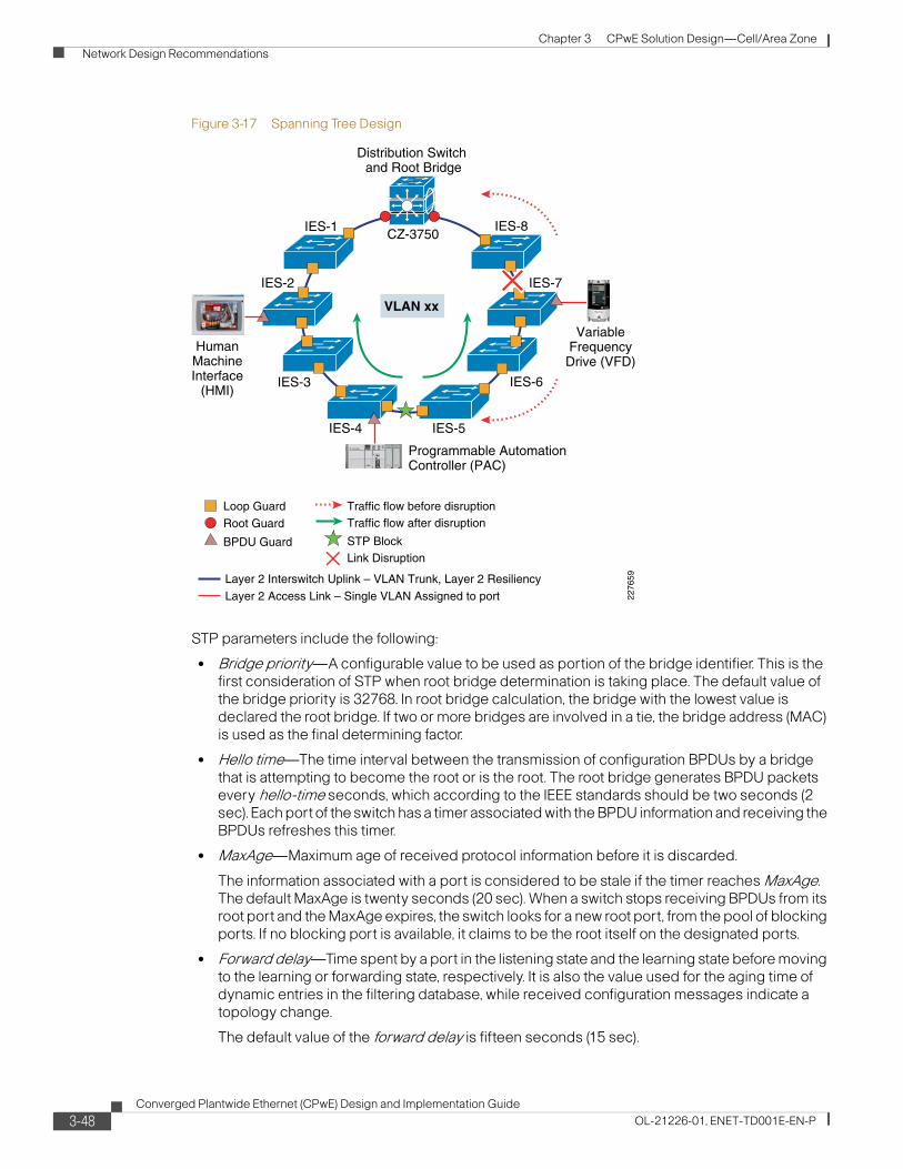
Chapter 3 CPwE Solution Design—Cell/Area Zone Network Design Recommendations
Figure 3-17 Spanning Tree Design
STP parameters include the following:
• Bridge priority—A configurable value to be used as portion of the bridge identifier. This is the first consideration of STP when root bridge determination is taking place. The default value of the bridge priority is 32768. In root bridge calculation, the bridge with the lowest value is declared the root bridge. If two or more bridges are involved in a tie, the bridge address (MAC) is used as the final determining factor.
• Hello time—The time interval between the transmission of configuration BPDUs by a bridge that is attempting to become the root or is the root. The root bridge generates BPDU packets every hello-time seconds, which according to the IEEE standards should be two seconds (2 sec). Each port of the switch has a timer associated with the BPDU information and receiving the BPDUs refreshes this timer.
• MaxAge—Maximum age of received protocol information before it is discarded.
The information associated with a port is considered to be stale if the timer reaches MaxAge. The default MaxAge is twenty seconds (20 sec). When a switch stops receiving BPDUs from its root port and the MaxAge expires, the switch looks for a new root port, from the pool of blocking ports. If no blocking port is available, it claims to be the root itself on the designated ports.
• Forward delay—Time spent by a port in the listening state and the learning state before moving to the learning or forwarding state, respectively. It is also the value used for the aging time of dynamic entries in the filtering database, while received configuration messages indicate a topology change.
The default value of the forward delay is fifteen seconds (15 sec).
VLAN xx
HumanMachineInterface
(HMI)
IES-1
IES-7IES-2
IES-8CZ-3750
Distribution Switch and Root Bridge
IES-3
IES-4 IES-5
IES-6
VariableFrequencyDrive (VFD)
Programmable AutomationController (PAC)
Root Guard
Loop Guard
BPDU Guard
Traffic flow before disruption
STP BlockLink Disruption
Traffic flow after disruption
2276
59
Layer 2 Access Link – Single VLAN Assigned to port
Layer 2 Interswitch Uplink – VLAN Trunk, Layer 2 Resiliency
3-48Converged Plantwide Ethernet (CPwE) Design and Implementation Guide
OL-21226-01, ENET-TD001E-EN-P

Chapter 3 CPwE Solution Design—Cell/Area Zone Network Design Recommendations
• Diameter—Maximum number of bridges between any two points of attachment of end stations. This is an optional parameter with no default. The range is 2 to 7. When the network diameter is specified, the switch automatically sets timing parameters (forward-delay, hello-time, and max-age) for a network of that diameter. If not specified (Cisco and Rockwell Automation recommendation) then the MaxAge parameter limits the topology diameter, which is by default 20 seconds or roughly 20 switches. Network diameter can have a profound effect on the operation of STP and the network as a whole because the latency of BPDUs increases as the network grows in diameter. If the configuration is used and the network is larger than the configuration suggests, the network may inadvertently split with unintended blocked connections, thus leaving sections of the network unable to communicate with other sections.
• Port cost(s)—Contribution of the path through this port, when the port is the root port, to the total cost of the path to the root for this bridge. The cost of each port between a given bridge and the root bridge contributes to the overall path cost. Some of the default values used are as follows:
– Gig E (1000 Mbps)—4
– OC-12 (622 Mbps)—6
– OC-3 (155 Mbps)—14
– FastE (100 Mbps)—19
– Ethernet (10 Mbps)—100
For more on configuring Spanning Tree in industrial Ethernet switches, refer to the following URL: http://www.cisco.com/en/US/docs/switches/lan/cisco_ie3000/software/release/12.2_50_se/configuration/guide/swstp.html#wp1082107
MSTP has additional configuration considerations from RPVST+. Where RPVST+ will by default operate in every available VLAN, MSTP maps multiple VLANs to the same Spanning Tree instance. MSTP does use the same rapid STP for quick network convergence. The key additional considerations when deploying MSTP in an IACS network include the following:
• Regions—Regions are defined by switches with common MST configurations: region name, given configuration version, and VLAN-to-instance mapping. Switches are configured as part of the same MST region by specifying the same configuration.
• Instances—Within a region, multiple Spanning Tree instances can exist. An instance may contain one or more VLANs. An instance can have specific Spanning Tree parameters for configured root, secondary root and port priority.
For the scope of testing reflected in this CPwE DIG, MST regions or instances were not tested. Our testing reflected default MSTP settings, which essentially reflect a single MST region and instance. Medium to large plants may consider applying MST Regions and instances for management and optimal convergence.
MSTP also has a parameter for maximum hop count. In rapid Spanning Tree or RPVST+, the maximum hop count was, as described, a derived concept based upon aging times. In MSTP, this is directly configurable, but be aware that the maximum aging time is also in affect. If the MSTP hop count is changed, the maximum age time may also need updates. The default settings for these suggest a maximum diameter of 20 hops or switches. These values can be increased.
3-49Converged Plantwide Ethernet (CPwE) Design and Implementation Guide
OL-21226-01, ENET-TD001E-EN-P

Chapter 3 CPwE Solution Design—Cell/Area Zone Network Design Recommendations
EtherChannel
The key design consideration when deploying EtherChannel include the following:
• Create a port-channel interface for every EtherChannel link between a pair of switches. The same VLAN considerations should be applied to port-channels as the uplink ports.
• Assign the relevant interface(s) to a channel-group and use mode active to set the interface into a LACP EtherChannel.
• Maintain the STP configuration in the switch global settings, on the distribution switch downlinks and on the host or access ports on the industrial Ethernet switches.
Figure 3-18 EtherChannel
If using stacked-switches as a redundant distribution switches, it is important to use the MAC-persistence feature to maintain the EtherChannel link in the case of failure of the switch with the switch stack MAC. If the persistence feature is not used and the switch with the MAC also used for the stack fails, the stack will choose another MAC address which forces the EtherChannel to shutdown and restart, thus eliminating the fast resiliency feature of an EtherChannel link. MAC-persistence ensures that the stack continues using the MAC address if the switch with that MAC fails. There are operational considerations when this situation occurs:
• Rebooting of the stack is recommended at the next planned downtime to reset the MAC address.
• If a failed switch in a stack is removed, do not reuse that switch in the network until the original stack is re-booted to avoid redundant MAC addresses in the network, as the stack will continue to use the MAC address associated with the failed switch until rebooted.
EtherChannel LinkE
VLAN xx
IES-1
IES-7IES-2
IES-8
CZ-3750
Distribution Switch and Root Bridge
IES-3
IES-4 IES-5
IES-6
ProgrammableAutomation
Controller (PAC)
2276
60Root Guard
Loop Guard
BPDU Guard
Traffic flow before disruption
Link Disruption
Traffic flow after disruption
Layer 2 Access Link – Single VLAN Assigned to port
Layer 2 Interswitch Uplink – VLAN Trunk, Layer 2 Resiliency
E
E E
E
E E
E E
VariableFrequencyDrive (VFD)
3-50Converged Plantwide Ethernet (CPwE) Design and Implementation Guide
OL-21226-01, ENET-TD001E-EN-P

Chapter 3 CPwE Solution Design—Cell/Area Zone Network Design Recommendations
Flex Links
The key design considerations when deploying Flex Links include the following:
• Deploy Flex Links on the Access switches (versus distribution switches). In CPwE testing, Flex Links did not converge as rapidly when deployed on the stacked distribution switches.
• Configure an uplink port to use the other uplink port as a backup interface. The port with the configuration is known as the active port, the other is known as the backup port. Either port may actually be on or in standby mode, depending on which failed most recently. The interface in standby mode is being blocked by Flex Links. Flex Links keeps the most recently failed port in standby mode when the link is restored and switches when the on link fails.
• Apply the multicast fast-convergence when configuring the Flex Link interfaces.
• Turn off Spanning Tree settings on both of the Flex Links ports. The Spanning Tree settings on all switches and other ports should remain, including the downlink ports on the distribution switch and host or access ports on the industrial Ethernet switches.
The design considerations for Flex Links are depicted in Figure 3-18.
Figure 3-19 Flex Links
VariableFrequencyDrive (VFD)VLAN xx
IES-1
IES-7IES-2
IES-8
CZ-3750
Distribution Switch and Root Bridge
IES-3
IES-4 IES-5
IES-622
7661
AB
Flex Links port, ActiveFlex Links port, Backup
Traffic flow after disruption
Link Disruption
A
B
Root Guard
Loop Guard
BPDU Guard
Traffic flow before disruption
Layer 2 Access Link – Single VLAN Assigned to port
Layer 2 Interswitch Uplink – VLAN Trunk, Layer 2 Resiliency
ProgrammableAutomation
Controller (PAC)
3-51Converged Plantwide Ethernet (CPwE) Design and Implementation Guide
OL-21226-01, ENET-TD001E-EN-P
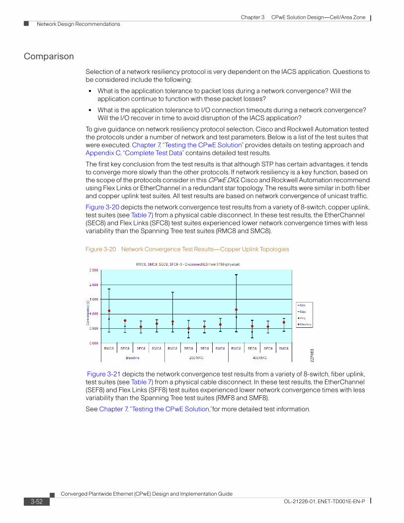
Chapter 3 CPwE Solution Design—Cell/Area Zone Network Design Recommendations
Comparison
Selection of a network resiliency protocol is very dependent on the IACS application. Questions to be considered include the following:
• What is the application tolerance to packet loss during a network convergence? Will the application continue to function with these packet losses?
• What is the application tolerance to I/O connection timeouts during a network convergence? Will the I/O recover in time to avoid disruption of the IACS application?
To give guidance on network resiliency protocol selection, Cisco and Rockwell Automation tested the protocols under a number of network and test parameters. Below is a list of the test suites that were executed. Chapter 7, “Testing the CPwE Solution” provides details on testing approach and Appendix C, “Complete Test Data” contains detailed test results.
The first key conclusion from the test results is that although STP has certain advantages, it tends to converge more slowly than the other protocols. If network resiliency is a key function, based on the scope of the protocols consider in this CPwE DIG, Cisco and Rockwell Automation recommend using Flex Links or EtherChannel in a redundant star topology. The results were similar in both fiber and copper uplink test suites. All test results are based on network convergence of unicast traffic.
Figure 3-20 depicts the network convergence test results from a variety of 8-switch, copper uplink, test suites (see Table 7) from a physical cable disconnect. In these test results, the EtherChannel (SEC8) and Flex Links (SFC8) test suites experienced lower network convergence times with less variability than the Spanning Tree test suites (RMC8 and SMC8).
Figure 3-20 Network Convergence Test Results—Copper Uplink Topologies
Figure 3-21 depicts the network convergence test results from a variety of 8-switch, fiber uplink, test suites (see Table 7) from a physical cable disconnect. In these test results, the EtherChannel (SEF8) and Flex Links (SFF8) test suites experienced lower network convergence times with less variability than the Spanning Tree test suites (RMF8 and SMF8).
See Chapter 7, “Testing the CPwE Solution,”for more detailed test information.
3-52Converged Plantwide Ethernet (CPwE) Design and Implementation Guide
OL-21226-01, ENET-TD001E-EN-P

Chapter 3 CPwE Solution Design—Cell/Area Zone Network Design Recommendations
Figure 3-21 Network Convergence Test Results—Fiber Uplink Topologies
Cisco and Rockwell Automation also evaluated EtherChannel and Flex Links designs with I/O applications producing multicast traffic. The objective of these test cases was to determine whether the protocols would converge fast enough to avoid application timeouts. Key observations from our testing included the following:
• As shown in Figure 3-22, only Flex Links consistently converged the multicast traffic in less than 100 ms as measured by the test traffic generator.
• Application timeouts were rare, but occurred more often in the EtherChannel test suites, especially in the stack master switch failure/restart test cases.
For this reason, Cisco and Rockwell Automation could only recommend Flex Links in a redundant star topology to meet the recovery requirements of a CIP I/O application. EtherChannel may be sufficient for some CIP I/O applications and does have advantages over Flex Links on some points (notably use of both links), and is considered a viable option.
Figure 3-22 Network Convergence—EtherChannel and Flex Links with Fiber Uplinks
3-53Converged Plantwide Ethernet (CPwE) Design and Implementation Guide
OL-21226-01, ENET-TD001E-EN-P

Chapter 3 CPwE Solution Design—Cell/Area Zone Network Design Recommendations
To summarize the network resiliency testing, in Table 3-9, the topology, protocol and uplink media combinations are plotted against the various application traffic types indicating which combinations were able to meet the availability requirements. Note that the resiliency technologies covered in this version of the solution generally do not recover quickly enough for safety and motion applications, as defined in “Availability” section on page 3-7, to avoid system outages. This version of the solution does not specifically target Safety and Motion applications. Other available technologies, namely Resilient Ethernet Protocol (REP) and Device Level Ring (DLR) are targeted to cover more challenging resiliency requirements, but are not covered in this version of the solution.
*EtherChannel may be considered for time-critical applications where a standard solution is required, but with the understanding that recovery may not always occur in a timeframe required by these applications.
Multicast ManagementMulticast traffic is an important consideration of a Cell/Area IACS network, because it is used by some of the key IACS communication protocols, such as CIP. Unmanaged multicast traffic is treated by the network infrastructure as a Layer-2 broadcast; every endpoint on the network receives the message. The impact increases exponentially as more multicast producing endpoints are added to the LAN. Internet Group Management Protocol (IGMP) is the standard method to manage multicast traffic. IGMP enables the network infrastructure to understand which endpoints are interested in which multicast data, and thus to forward the messages only to those endpoints that want them. This reduces the amount of traffic the network and endpoints must handle. See Figure 3-23.
Table 3-9 Network Resiliency Testing
Topology Resiliency Protocol Media Information HMITime Critical Motion
Ring Rapid Spanning Tree Copper X
Rapid Spanning Tree Fiber X
Redundant Star Rapid Spanning Tree Copper X
Rapid Spanning Tree Fiber X
EtherChannel (LACP) Copper X
EtherChannel (LACP) Fiber X *
Flex Links Copper X
Flex Links Fiber X X
3-54Converged Plantwide Ethernet (CPwE) Design and Implementation Guide
OL-21226-01, ENET-TD001E-EN-P

Chapter 3 CPwE Solution Design—Cell/Area Zone Network Design Recommendations
Figure 3-23 IGMP Impact on Multicast Network Traffic
Note Cisco and Rockwell Automation recommend that the network infrastructure be configured to manage multicast traffic.
Note Layer-2 access switches should be configured to perform IGMP snooping. When IGMP snooping is enabled, the switch listens to IGMP traffic and develops a table that lists the multicast groups and the end-devices. Thus, when a multicast packet is received, the switch forwards it only to end-devices that want it. In addition, the Layer-3 distribution switch where the LAN is connected should be configured to perform the IGMP Querier function.
Although the number of multicast addresses in a VLAN or subnet is not typically an issue, it is a consideration under certain scenarios. EtherNet/IP devices can support up to 32 multicast addresses. Typically, however, an EtherNet/IP device only uses one multicast addresses per connection. controllers can potentially use more for doing peer communications, but that may also be alleviated by choosing unicast messaging (an option in Rockwell Automation controllers). This is important because the network infrastructure has limits on the number of multicast addresses that can be supported. For example, the Cisco and Rockwell Automation industrial Ethernet switches can handle up to 256 multicast addresses. In a large, flat network, these limits may come into play. It is theoretically possible to configure a VLAN to overrun the number of multicast addresses that the industrial Ethernet switches can handle. When the switch's multicast address space is overrun, the switch simply broadcasts the multicast traffic to all IACS devices. In CPwE testing, when this situation occurred, application connections became unstable (often dropping and restarting) making the overall application unstable. This can be avoided using standard EtherNet/IP configuration guidelines and by following our logical segmentation guidelines.
In this CPwE solution architecture, IACS multicast packets are separated from the enterprise traffic by a DMZ. If they did, there is the distinct potential of redundant multicast group addresses being used that could lead to disruptions in both the IACS and the relevant IT application. For this and many other reasons, this solution architecture recommends a Demilitarized zone (DMZ) between the Manufacturing and Enterprise zone to ensure that IACS multicast traffic and IT-driven multicast traffic remain separate.
The rest of this section describes the key aspects of multicast management, including the following:
• IGMP Overview to describe the standard developed and the relevant versions
• IGMP Process describes the basic workings of the protocol
2208
86
No. of Control Devices
Mbp
s
Producer-Consumer
Multicastwith IGMPSnooping
Multicast Trafficwith no management
Unicast Traffic
3-55Converged Plantwide Ethernet (CPwE) Design and Implementation Guide
OL-21226-01, ENET-TD001E-EN-P
Chapter 3 CPwE Solution Design—Cell/Area Zone Network Design Recommendations
IGMP Overview
The Internet Group Management Protocol (IGMP) is an integral part of IP. It must be implemented by all hosts wishing to receive IP multicasts. IGMP is part of Layer 3 and uses IP datagrams to transmit information about multicast groups. IGMP is a protocol between routers and hosts that allows group membership lists to be dynamically maintained. It should be noted though that IGMP does not determine how multicast packets are forwarded, but by listening or snooping to the IGMP messages, the network infrastructure can switch and route multicast traffic only to those hosts that request traffic from the specific multicast group. The “Multicast Traffic Flow” section on page 3-59 describes how multicast traffic is handled with network infrastructure capable of IGMP snooping.
IGMP Versions
The IGMP has been developed over time. Three major versions of the protocol exist. They mostly build upon each other and are generally backward compatible. In brief they are as follows:
• Version 1, the initial version, hosts can join a multicast group. A query function exists to monitor group interest. Typically, after a host fails to respond to three queries, the host is dropped from the group.
• Version 2, the most commonly support version, works similar to Version 1 except that hosts can actively leave a group.
• Version 3, is the latest, but not as common version. Version 3 allows for source filtering, where a consumer can choose from which producers to receive information on a particular group.
The Cisco and Rockwell Automation industrial Ethernet switches support end-hosts using all three versions. The switches do not support the source filtering feature in Version 3, although do handle the IGMP Version 3 messages. The majority of IACS EtherNet/IP devices support IGMP Version 2. If devices do support version 1 or 3, they should interoperate with the Cisco and Rockwell Automation industrial Ethernet switches. This design guidance will assume end-hosts and network infrastructure support IGMP Version 2. Cisco and Rockwell Automation recommend using end-hosts that support and are configured to operate in IGMP Version 2 to avoid any compatibility issues.
Multicast Addressing
A range of IPv4 addresses has been reserved for multicast use. The Internet Assigned Numbers Authority (IANA) assigned a class D address space to be used for IP multicast. This means that all IP multicast group addresses will fall in the range of 224.0.0.0 to 239.255.255.255. Each multicast group essentially is one multicast address.
Multiple protocols use multicast in their communication, including EtherNet/IP. EtherNet/IP specifies how end-devices generate or choose the multicast address for the groups they may produce or consume. For the most part, implementers do not have to get involved in the assignment of multicast addresses, as the end-hosts manage that on their own.
Theoretically, it is possible the multicast addresses in the IACS space may overlap with multicast addresses used in the Enterprise networks. Issues could arise if two different applications used the same multicast address within the same network zone. But a number of precautions outlined in this solution and in the underlying technology ensure that does not occur, including the following:
• EtherNet/IP multicast traffic is designed not to be routed.
• Strong segmentation between Manufacturing and Enterprise zones with firewalls ensure that the multicast traffic from either do not intermingle.
3-56Converged Plantwide Ethernet (CPwE) Design and Implementation Guide
OL-21226-01, ENET-TD001E-EN-P

Chapter 3 CPwE Solution Design—Cell/Area Zone Network Design Recommendations
IGMP Process
The protocol describes a method for which end-hosts can subscribe to or join a multicast group and receive packets sent to that group. The concept of a process joining a multicast group on a given host interface is fundamental to multicasting. Membership in a multicast group on a given interface is dynamic (that is, it changes over time as processes join and leave the group). This means that IACS devices can dynamically join multicast groups based on the applications that they execute. The network infrastructure listens to these messages and when properly configured sends the multicast traffic between the producers and consumers.
Because IGMP is a Layer-3 protocol, this also means that the network infrastructure can send the multicast traffic to other subnets within the overall network, referred to as multicast routing. Multicast routing requires routers or Layer-3 switches enabled with Protocol Independent Multicast (PIM) to manage routing multicast traffic between producers and consumers in different VLANs or subnets. As IACS multicast traffic is constrained to the VLAN or subnet (see discussion on Time To Live or TTL below), this CPwE DIG does not focus on multicast routing, but does focus on multicast traffic and IGMP in a Layer-2 model.
In the Layer-2 model, there are two key functions played by the network infrastructure to manage multicast traffic. First, there is a querier function. IGMP queriers use IGMP messages to keep track of group membership on each of the networks that are physically attached to the router. The following rules apply:
• A host sends an IGMP report when it wants to join a multicast group. This is referred to as an unsolicited join.
• In EtherNet/IP, a host joins a group based on the TCP-based connection-open process that is conducted between producers and consumers.
• An IGMP querier sends IGMP queries at regular intervals to see whether any hosts still have processes belonging to any groups. The querier sends a query out each interface on the relevant VLAN. The group address in the query is 0 because the router expects one response from a host for every group that contains one or more members on a host. The IGMP Querier can send global or group specific queries.
• A host responds to an IGMP query by sending an IGMP report if the host still wants to receive traffic for that multicast group.
• In IGMPv2 a host will send an IGMP leave if that host no longer wants to receive traffic for a specific multicast group.
• If more than one switch or router is configured to be IGMP querier in a given VLAN, the switch or router with the lowest IP address will take this role as specified by the IGMP protocol v2.
• Global queries are sent to all ports, like a broadcast.
Note IGMP queriers do not by default track multicast groups.
The second key function is Internet Group Management Protocol (IGMP) snooping. IGMP snooping is a multicast constraining mechanism that runs on a Layer 2 LAN switch. IGMP snooping requires the LAN switch to examine some Layer 3 information (IGMP join/leave messages) in the IGMP packets sent between the hosts and the querier. The switch maintains a multicast group table similar in function to the CAM table used to track MAC addresses for switching packets. The IGMP snooping switch also tracks the ports (may be more than one per VLAN) on which multicast routers or IGMP query messages are heard, called the mrouter.
Note that IGMP query and snooping are two separate functions on industrial Ethernet switches; enabling one or the other does not enable both.
3-57Converged Plantwide Ethernet (CPwE) Design and Implementation Guide
OL-21226-01, ENET-TD001E-EN-P

Chapter 3 CPwE Solution Design—Cell/Area Zone Network Design Recommendations
The following are two joining scenarios:
Scenario A: Host A is the first host to join a group in the segment.
Step 1 Host A sends an unsolicited IGMP Membership report.
Step 2 The switch intercepts the IGMP Membership report that was sent by the host that wanted to join the group.
Step 3 The switch creates a multicast entry for that group and links it to the port on which it has received the report and to all mrouter ports.
Step 4 The switch forwards the IGMP report to all mrouter ports. The reason is to ensure upstream switches and the IGMP Querier receive the IGMP report, and update their respective multicast routing tables.
Scenario B: Host B now is the second host on the switch to join the same group.
Step 1 Host B sends an unsolicited IGMP Membership report.
Step 2 The switch intercepts the IGMP Membership report sent by the host that wants to join the group.
Step 3 The switch does not necessarily forward the IGMP report to all router ports. Actually, the switch forwards IGMP reports to mrouter ports using proxy reporting, and only forwards one report per group within 10s.
In order to maintain group membership, the multicast router sends a IGMP query every 60 seconds. This query is intercepted by the switch, and forwarded to all ports on the switch. All hosts that are members of the group answer that query. But, given the fact that the switch intercepts the reply report as well, the other hosts do not see each of the other reports, and thus, all hosts send a report (instead of one per group). The switch then uses Proxy Reporting as well, to forward only one report per group among all received responses.
Assume Host A wants to leave the group, but Host B still wants to receive the group:
Step 1 The switch captures the IGMP Leave message from Host A.
Step 2 The switch issues a group-specific IGMP query for the group on that port (and only on that port).
Step 3 If the switch does not receive a report, it discards this port from the entry. If it receives a response from that port, it does nothing and discards the leave.
Note Cisco and Rockwell Automation industrial Ethernet switches support a port-level “Immediate-Leave” feature. This feature removes an interface from the multicast group entry immediately when a Leave is received, versus sending a group-specific query. Cisco and Rockwell Automation do not recommend using this feature for IACS networks. This feature is disabled by default.
Step 4 Host B is still interested by that group on that switch. This would not be the last non-router port in the entry. Therefore, the switch does not forward the Leave message.
3-58Converged Plantwide Ethernet (CPwE) Design and Implementation Guide
OL-21226-01, ENET-TD001E-EN-P

Chapter 3 CPwE Solution Design—Cell/Area Zone Network Design Recommendations
Now, assume Host B wants to leave the group and Host B is the last IACS device interested by this group in this segment:
Step 1 The switch captures the IGMP leave message from Host B.
Step 2 The switch issues a group-specific IGMP query for that group on that port.
Step 3 If the switch does not receive a report, it discards this port from the entry.
Step 4 This is the last non-router port for that Group Destination Address (GDA). The switch forwards the IGMP Leave message to all router ports and removes the entry from its table.
The Time to Live (TTL) field in the IP header of reports, queries and most IACS network multicast data packets is set to 1. A multicast datagram with a TTL of 0 is restricted to the same host. By default, a multicast datagram with a TTL of 1 is restricted to the same subnet. Higher TTL field values can be forwarded by the router. Most IACS network multicast traffic has a TTL equal to 1, which restricts the traffic to the subnet or VLAN. This tends to be set by the IACS device vendor and is not configurable. If the TTL were increased, the traffic could be routed if multicast routing protocols on appropriate routers (e.g., a Layer-3-capable distribution switch), would be able to route the multicast packets. The TTL in the IP packet is decremented by 1 every time it passes through a routed hop. The TTL is not decremented when passing through Layer-2 hops, or in other words while it is in a VLAN or subnet. This version of the CPwE solution does not cover routing of multicast traffic.
For information on IP multicasting, visit Cisco Technology Support at the following URLs:
http://www.cisco.com/en/US/partner/tech/tk828/technologies_white_paper09186a0080092942.shtml
http://www.cisco.com/en/US/tech/tk1330/tsd_technology_support_technical_reference_chapter09186a00807598c3.html
http://www.cisco.com/en/US/partner/tech/tk828/tsd_technology_support_protocol_home.html
http://www.cisco.com/en/US/partner/tech/tk828/tk363/tsd_technology_support_sub-protocol_home.html
http://www.cisco.com/en/US/tech/tk828/tech_brief09186a00800a4415.html
For more information on configuring and implementing IGMP, see Chapter 5, “Implementing and Configuring the Cell/Area Zone.”
Multicast Traffic Flow
This section describes multicast traffic flow in a Layer-2 environment (i.e., VLAN or subnet). The traffic flow is described in two scenarios: normal operations and flooding, which occurs after a topology change.
Normal Operations
Without IGMP snooping, switches in a Layer 21 environment treat multicast traffic as broadcast traffic, significantly increasing bandwidth consumed and end-device processing. With IGMP Snooping in the Layer 2 switches, the switch is able to restrict switching of multicast packets out to only those ports that require it. The switch uses the multicast table and mrouter entries decide on
1. It is important to note that routing multicast traffic is possible and there is extensive description of such in the above references, but for IACS, EtherNet/IP environments, the application ensures the multicast is not routable by setting the TTL to 1, indicating the packet should not be routed.
3-59Converged Plantwide Ethernet (CPwE) Design and Implementation Guide
OL-21226-01, ENET-TD001E-EN-P

Chapter 3 CPwE Solution Design—Cell/Area Zone Network Design Recommendations
which ports to forward IGMP and multicast packets. Assuming IGMP snooping is in place, there are essentially two modes of operation, normal operations and multicast flooding after a topology change.
In normal operations, the switch only forwards multicast packets received out to ports that need it, including the following:
1. Any port on which an IGMP report was received
2. The mrouter port, unless the multicast packet was received from that port.
Note Switches will not send the packet to the same port on which a multicast packet was received.
The traffic flow for multicast is depicted in Figure 3-24.
Figure 3-24 Multicast Traffic Flow
Figure 3-24 depicts a ring topology. Spanning tree is the network resiliency protocol in place. Figure 3-24 shows how the multicast packet traverses the topology from the producer to the consumer. The multicast packet is forwarded in the following manner:
1. The multicast packet is forwarded from the ingress switch (IES-4) to the IGMP querier switch, in this case the distribution switch (CZ-3750).
2. The multicast router and subsequent switches forward the multicast packet on ports which the multicast group has been registered until the packet reaches the multicast consumer.
Figure 3-24 assumes the following:
• IGMP snooping is enabled on all of the switches. This is the Cisco and Rockwell Automation recommendation.
VLAN xx
STP Block
Traffic flow before disruption
mrouter Port
Registered for Multicast group
HMI
IES-1
IES-7IES-2
IES-8CZ-3750
Distribution Switch and Acting IGMP Querier
IES-3
IES-4 IES-5
IES-6
VFD
MuliticastProducer
MuliticastConsumer
Controller
2276
65
3-60Converged Plantwide Ethernet (CPwE) Design and Implementation Guide
OL-21226-01, ENET-TD001E-EN-P

Chapter 3 CPwE Solution Design—Cell/Area Zone Network Design Recommendations
• A version of Spanning Tree is enabled on all of the switches. The distribution switch is the acting root bridge, which is the Cisco and Rockwell Automation recommendation.
• The distribution switch is configured to be the acting IGMP querier (i.e., has the lowest IP address in the subnet). This is the Cisco and Rockwell Automation recommendation.
• The multicast consumer has reported interest in the multicast group which the multicast producer uses. This is described earlier in the IGMP process section.
It is important to note in this operation that all multicast traffic in a Cell/Area zone VLAN or subnet is seen by the IGMP querier switch. Therefore, to minimize the amount of multicast traffic on the switch uplinks and to limit potential bottlenecks, Cisco and Rockwell Automation recommend that the IGMP querier function is established at a central point of the normally operating network topology. Depending on the network topology and resiliency protocol, the recommended location of the IGMP querier includes the following:
• For a redundant star topology, the central or distribution switch should be the configured IGMP querier, which is also the STP root bridge.
• For a ring topology, the primary querier should be the STP root.
• For a linear topology, the primary querier should be near the center of the line.
Although this is our recommendation, if the IGMP querier happens to be located towards the natural ends of a topology, multicast traffic should still be appropriately handled by the network infrastructure. This situation can occur in the event of a network outage.
Resiliency Operations
As multicast traffic is critical to IACS network applications, it is important to consider how multicast traffic is handled during periods of network recovery from outages. This section reviews how the multicast traffic is handled during a network recovery and normal traffic patterns are restored.
Under normal operations, an industrial Ethernet switch stores information that is relevant to the existing network topology. For example, the switch stores the port(s) on which queries/multicast routing information are received indicating direction of the IGMP querier. In the case of a network outage or event, the resiliency protocols take steps to restore the network by unblocking relevant ports, thereby changing the network topology. The information in the multicast table has to be rebuilt to ensure it is correct. The network infrastructure must take steps to ensure the multicast traffic recovers in a timely manner as well. The key steps in this process include:
1. Failure occurs, for example, link down noticed between two switches.
2. Resiliency protocol sends topology change notification (TCN) to open a blocked port.
3. When a TCN is received, IGMP snooping switch will start forwarding multicast and IGMP packets out the respective “resiliency” ports, for example the STP ports, where BPDU packets are sent/received for a determined period of time. In a properly configured network, this results in “flooding” the multicast packets to all network infrastructure devices. This flooding will occur for a configurable period of time,
4. During the flooding period, the IGMP process of learning which ports want various multicast groups will be accelerated. This process starts by the Root switch (if Spanning Tree is enabled) sending a Global Leave message. This message is forwarded by the switches towards the IGMP querier (via the mrouter port). When the IGMP Querier receives a Global Leave, it starts to send general queries that enable the network infrastructure to re-learn the multicast interests of IACS devices after the topology change. Generally, a number of queries are sent before.
5. When the TCN flooding period expires, switches have re-learned the multicast groups and return to normal multicast traffic handling and IGMP process as specified above.
3-61Converged Plantwide Ethernet (CPwE) Design and Implementation Guide
OL-21226-01, ENET-TD001E-EN-P

Chapter 3 CPwE Solution Design—Cell/Area Zone Network Design Recommendations
Note that the above assumes Spanning Tree as the resiliency protocol. For EtherChannel and Flex Links, no need for flooding or IGMP relearning is required because these protocols handle the multicast traffic and IGMP differently. In EtherChannel, the underlying EtherChannel load balancing ensures all traffic, including multicast, is sent on the active links. The IGMP learning is applied to the port-channel, which does not require any “relearning” when a single link fails in a multi-link EtherChannel connection. In Flex Links with the multicast fast-convergence feature, both links involved are designed to receive the relevant multicast groups. The Flex Links switch simply blocks the multicast on one port until the port becomes active.
Figure 3-25 depicts the multicast traffic flow in the case of a topology change.
Figure 3-25 Multicast Traffic Flow with Topology Change
Figure 3-25 assumes the following:
• IGMP snooping is enabled on all of the switches.
• A version of Spanning Tree is enabled on all of the switches. The distribution switch is the acting root bridge.
• The distribution switch is configured to be the acting IGMP querier.
• The multicast consumer has reported interest in the multicast group which the multicast producer uses.
• Global leave from querier has been issued ensuring mrouter port is updated.
• The IGMP Topology Change Notice (TCN) timer has started after the STP event but not expired.
In a properly configured network, the multicast flooding mode only impacts uplink connections, which in general have enough bandwidth to handle to additional load. The flooding mode generally has a timer which is designed to allow the IGMP process to relearn all the multicast tables.
VLAN xx
STP Block
Traffic flow during TCN flooding
mrouter Port
Registered for Multicast group
HMI
IES-1
IES-7IES-2
IES-8CZ-3750
Distribution Switch and Acting IGMP Querier
IES-3
IES-4 IES-5
IES-6
VFD
MuliticastProducer
MuliticastConsumer
Controller
2276
66
Link Disruption
Resiliency Port
3-62Converged Plantwide Ethernet (CPwE) Design and Implementation Guide
OL-21226-01, ENET-TD001E-EN-P

Chapter 3 CPwE Solution Design—Cell/Area Zone Network Design Recommendations
Once the multicast flooding timer expires, multicast flooding on resiliency ports terminates and normal IGMP process and multicast traffic handling are in effect. Figure 3-26 depicts the multicast traffic flow after the timer express and the link is still down.
Figure 3-26 Multicast Traffic Flow After Time Expires
Of the resiliency protocols covered in this CPwE DIG, only Spanning Tree uses the multicast “flooding” mechanism in a topology change. Flex Links does not need to as it leaks IGMP reports out both ports it manages, thereby ensuring the multicast packets are arriving when the port is required. EtherChannel simply recalculates its load balancing algorithm to start forwarding multicast packets on available links.
IGMP Design Considerations
The key multicast management recommendation is to enable the IGMP process in the Cell/Area zone. To enable and configure IGMP, Cisco and Rockwell Automation recommends:
1. Enable IGMP snooping and querier on all the industrial Ethernet switches as well as the distribution switch/router. Do not change any of the IGMP snooping default settings.
2. Configure the IGMP querier on the distribution switch or central to the Cell/Area zone topology. When multiple IGMP queriers are on a VLAN, the IGMP protocol calls for the querier with the lowest IP address to take over the querier function. Therefore, the distribution switch should have the lowest IP address in the subnet.
Quality-of-Service (QoS)This section describes how a relatively complex, but powerful network function is applied to industrial Ethernet and IACS networks. Although a complex topic, QoS is integrated into Express Setup and Smartports, therefore, the utilization of QoS is built-in when deploying an industrial
VLAN xx
Traffic flow after disruption
mrouter Port
Registered for Multicast group
HMI
IES-1
IES-7IES-2
IES-8CZ-3750
Distribution Switch and Acting IGMP Querier
IES-3
IES-4 IES-5
IES-6
VFD
MuliticastProducer
MuliticastConsumer
Controller
2276
67
Link Disruption
3-63Converged Plantwide Ethernet (CPwE) Design and Implementation Guide
OL-21226-01, ENET-TD001E-EN-P

Chapter 3 CPwE Solution Design—Cell/Area Zone Network Design Recommendations
Ethernet network following the CPwE design and implementation steps. By following these steps, a network developer will get the benefits of QoS without having to take additional steps. The detail in this section is intended to help enable a implementers to enhance or tailor the QoS for their environment, if necessary. If such changes are made, Cisco and Rockwell Automation highly recommend sufficient testing of the changes are performed to ensure the desired effect is achieved. This section describes how QoS works in general and specifies the major QoS design considerations Cisco and Rockwell Automation developed for IACS networks.
QoS refers to network control mechanisms that can provide various priorities to different IACS devices or data flows, or guarantee a certain level of performance to a data flow in accordance with requests from the application program. QoS guarantees are important if the network performance is critical, especially for real-time IACS.
Note Cisco and Rockwell Automation recommend the application of QoS to the critical CIP Implicit I/O as well as the Explicit message traffic generated by IACS network devices.
As indicated in “Traffic Flows” section on page 3-19, non-CIP traffic (such as Internet HTTP) is highly likely on any IACS network. The IACS devices can support various traffic types natively, and certain functions (for example, monitoring) are implemented using common protocols. Also, Level 3 workstations and servers in the Manufacturing zone produce traffic of various types that may mix with the Cell/Area IACS network traffic. It is even possible to deploy voice and video into a Cell/Area IACS network, as they are based upon standard networking technologies. Manufacturers may want to take advantage of the openness that standard networks provide to introduce other services into the Manufacturing zone, without sacrificing the performance required by the IACS. QoS is a key mechanism to achieve this goal.
Beyond the performance implications, QoS also provides the following:
• Security, by placing priority on IACS device data, IACS networks are less-susceptible to a variety of attacks, especially denial-of-service (DoS) attacks on the network.
• Bandwidth utilization optimization by matching applications to the amount of bandwidth they receive in the network in times of congestion.
For this version of the CPwE solution architecture, Cisco and Rockwell Automation did not specifically test QoS settings or verify the benefits. However, as the ODVA has integrated end-device QoS into the EtherNet/IP specification and the Cisco and Rockwell Automation industrial Ethernet switches apply a QoS approach in the standard configuration and deployment, some background and design consideration is included here.
This section covers the basic concepts related to applying QoS in an IACS Cell/Area zone, including the following:
• QoS Background
• QoS Objectives and Application Service Level
• End-to-End Service Levels
• Identification and Marking
• Policing, Queuing and Scheduling
3-64Converged Plantwide Ethernet (CPwE) Design and Implementation Guide
OL-21226-01, ENET-TD001E-EN-P

Chapter 3 CPwE Solution Design—Cell/Area Zone Network Design Recommendations
QoS Background
QoS refers to the capability of a network to provide better service to selected network traffic. The primary goal of QoS is to provide priority including dedicated bandwidth, controlled jitter and latency (required by some real-time and interactive traffic), and improved loss characteristics. This applies especially to the IACS network traffic. Also important is making sure that providing priority for one or more flows does not make other flows fail.
For more background on QoS, the following readings are recommended:
• Enterprise QoS Solution Guide— http://www.cisco.com/en/US/docs/solutions/Enterprise/WAN_and_MAN/QoS_SRND/QoSIntro.html
• Internetworking Technology Handbook, Quality of Service— http://www.cisco.com/en/US/tech/tk1330/tsd_technology_support_technical_reference_chapter09186a0080759886.html
• IE 3000 Software Configuration Guide, Configuring QoS— http://www.cisco.com/en/US/docs/switches/lan/cisco_ie3000/software/release/12.2_50_se/configuration/guide/swqos.html#wp1284809
The discussion in this chapter is based on the basic QoS concepts outlined in the above documents.
QoS Objectives and Application Service Level
To apply QoS onto a network infrastructure, objectives, and application service levels are required. Each organization deploying a standard Ethernet and IP network for the plant floor should have an agreed upon set of objectives and application service levels that will drive the QoS approach, design, and configuration.
As stated earlier, in a IACS network, the IACS applications take precedence over other applications and traffic types as they directly impact key business metrics: uptime, efficiency and performance. The design and implementation of QoS in the industrial Ethernet switches was based on the following objectives aligned with the key business metrics:
• IACS network traffic should take priority over other applications (e.g. web-based, voice or video) in the Cell/Area zone.
• IACS network traffic tends to be very sensitive to latency, jitter and packet loss. The Service Level for IACS network traffic should minimize these.
• Different types of industrial Ethernet traffic (Motion, I/O, and HMI) have different requirements for latency, packet loss, and jitter. The service policy should differentiate service for these types of flows.
• The network developer would like non-IACS traffic (HTTP, E-mail, etc.) to have little or no affect on the IACS application.
Table 3-10 depicts the relative sensitivities of IACS network traffic versus typical Enterprise network traffic.
Since the original version of this solution, the ODVA has published standards that incorporate QoS marking by end-devices. These guidelines specify the markings for both Layer-3 QoS field (DSCP) and Layer 2 (class-of-service). These guidelines also establish relative priority for various types of IACS network traffic.
3-65Converged Plantwide Ethernet (CPwE) Design and Implementation Guide
OL-21226-01, ENET-TD001E-EN-P

Chapter 3 CPwE Solution Design—Cell/Area Zone Network Design Recommendations
Based on these specifications, one can build a model of relative importance of the traffic types found in an IACS network. Figure 3-27 depicts the relative importance of typical Enterprise traffic versus Cell/Area zone traffic.
Figure 3-27 Enterprise Traffic vs. Cell/Area Zone Traffic
Table 3-10 IACS Network Traffic versus Typical Enterprise Network Traffic
Traffic Type CIP Priority DSCP enabled by default 802.1D Priority disabled by default CIP Traffic Usage
PTP event (IEEE 1588)
N/A 59(‘111011’)
7 PTP event messages, used by CIP Sync
PTP management (IEEE 1588)
N/A 47(‘101111’)
5 PTP management messages, used by CIP Sync
CIP class 0 / 1 Urgent (3) 55(‘110111’)
6 CIP Motion
Scheduled (2) 47(‘101111’)
5 Safety I/O
I/O
High (1) 43(‘101011’)
5 I/O
Low (0) 31(‘011111’)
3 No recommendation at present
CIP UCMM CIP class 3
All 27(‘011011’)
3 CIP messaging
Critical Data
Video
Call Signaling
Best Effort
Voice
Bulk Data
Network Control
Scavenger
Critical DataVideo
Call Signaling
Best Effort
Voice
Bulk Data
Network Control
Scavenger
CIP ExplicitMessaging
CIP Motion
PTP Management,Safety I/Oand I/O
Typical Enterprise QoS
Cell/Area Zone QoS
OutputQueue 3
OutputQueue 4 OutputQueue 2
OutputQueue 1
2276
68
PTP-Event
3-66Converged Plantwide Ethernet (CPwE) Design and Implementation Guide
OL-21226-01, ENET-TD001E-EN-P

Chapter 3 CPwE Solution Design—Cell/Area Zone Network Design Recommendations
End-to-End Service Levels
Service levels refer to the actual end-to-end QoS capabilities, meaning the capability of a network to deliver service needed by specific network traffic from end-to-end or edge-to-edge. The services differ in their level of QoS strictness, which describes how tightly the service can be bound by specific bandwidth, delay, jitter, and loss characteristics.
Three basic levels of end-to-end QoS can be provided across a heterogeneous network:
• Best-effort service—Also known as lack of QoS, best-effort service is basic connectivity with no guarantees. This is best characterized by FIFO queues, which have no differentiation between flows.
• Differentiated service (also called soft QoS)—Some traffic is treated better than the rest (faster handling, more average bandwidth, and lower average loss rate). This is a statistical preference, not a hard and fast guarantee. This is provided by classification of traffic and the use of QoS tools such as priority queuing, Weighted Tail Drop (WTD) for queue buffer management, and shaped round-robin for queue servicing (see the referenced QoS documentation listed under the “QoS Background” section on page 3-65).
• Guaranteed service (also called hard QoS)—This is an absolute reservation of network resources for specific traffic. This is provided through various QoS tools.
Deciding which type of service is appropriate to deploy in the network depends on several factors:
• The application or problem to be solved. Each of the three types of service is appropriate for certain applications. This does not imply mandatory migration to differentiated services and then to guaranteed service. A differentiated service—or even a best-effort service—may be appropriate, depending on the IACS application requirements.
• The rate at which manufacturers can realistically upgrade their infrastructures. There is a natural upgrade path from the technology needed to provide differentiated services to that needed to provide guaranteed services, which is a superset of that needed for differentiated services.
• The cost of implementing and deploying guaranteed service is likely to be more than that for a differentiated service.
Typically, IACS networks have been best-effort service levels, as typically they carry limited amounts and types of traffic. But as the use of standard Ethernet and IP networking spreads in the plant and as that IACS networking is used for more applications, a different model will be required.
Note Cisco and Rockwell Automation recommend and implement in the standard configuration a differentiated service end-to-end in the Cell/Area zone.
The key reasons for choosing differentiated service include the following:
• Provides significant value over best-effort service as priority can be given to IACS network traffic, even prioritizing traffic flows within the application to better ensure.
• Provides flexibility to support peaks and spikes in bandwidth utilization by providing available network resources to those applications, while maintaining service to IACS network devices.
• IACS network traffic is generally not bandwidth intensive where they need specific amounts of the bandwidth guaranteed.
• Set once and left to operate without significant operational interaction. The differentiated services does not require updating or modification when new applications are introduced, although some modification may be required if the service policy is updated as applications are added.
3-67Converged Plantwide Ethernet (CPwE) Design and Implementation Guide
OL-21226-01, ENET-TD001E-EN-P

Chapter 3 CPwE Solution Design—Cell/Area Zone Network Design Recommendations
Identification and Marking
The first element to a QoS policy is to classify/identify the traffic that is to be treated differently. Classification and marking tools set this trust boundary by examining any of the following:
• Layer 2 parameters—802.1Q class-of-service (CoS) bits
• Layer 3 parameters—IP Precedence (IPP), Differentiated Services Code Points (DSCP), IP Explicit Congestion Notification (ECN), source/destination IP address
• Layer 4 parameters— L4 protocol (TCP/UDP), source/destination ports
• Layer 7 parameters— application signatures
The QoS model implemented in the IE switches focuses on the Differentiated Services or DiffServ model. One of the key goals of the DiffServ is to classify and mark the traffic as close to the source as possible. This allows for an end-to-end model where intermediary routers and switches simply forward the frame based on the predetermined marking. Do not trust markings that can be set by users on their PCs or other similar devices, because users can easily abuse provisioned QoS policies if permitted to mark their own traffic.
Following classification, marking tools can set an attribute of a frame or packet to a specific value. Such marking (or remarking) establishes a trust boundary that scheduling tools later depend on. Cisco and Rockwell Automation recommend the following:
• IACS network devices designed to mark and classify traffic in accordance with the ODVA's specification should be trusted(e.g., devices conforming to ODVA's CIP Networks Library, Volume 2, EtherNet/IP Adaptation of CIP Edition 1.6 November 2008 where QoS was introduced and enabled to mark their traffic).
• IACS network devices that are not designed to mark their network traffic (should not be trusted and the network infrastructure should classify and mark the ingress traffic from such devices. In this way, the traffic from legacy devices receives respective network priority even if newer, QoS-compliant devices exist in the network.
• Network uplinks and inter-switch connections are QoS trusted ports.
For the Cell/Area zone, the trust/no-trust can be depicted in Figure 3-28.
3-68Converged Plantwide Ethernet (CPwE) Design and Implementation Guide
OL-21226-01, ENET-TD001E-EN-P

Chapter 3 CPwE Solution Design—Cell/Area Zone Network Design Recommendations
Figure 3-28 QoS Trust/No-Trust in Cell/Area Zone
Within an enterprise, marking is done at either Layer 2 or Layer 3, using the following fields:
• 802.1Q/p Class of Service (CoS)—Ethernet frames can be marked at Layer 2 with their relative importance by setting the 802.1p User Priority bits of the 802.1Q header. Only three bits are available for 802.1p marking. Therefore, only 8 CoS (0-7) can be marked on Layer-2 Ethernet frames.
• IP Type of Service (ToS) byte—Layer-2 media often changes as packets traverse from source to destination, so a more ubiquitous classification occurs at Layer 3. The DiffServ model uses the six-bit DSCP field in the IP header for the marking.
Cisco and Rockwell Automation also recommend using DSCP (or type-of-service) markings whenever possible, because these are end-to-end, more granular and more extensible than Layer-2 markings.
Cisco and Rockwell Automation recommend the following steps to implement the identification and classification of IACS network traffic:
Step 1 Establish ACLs for each IACS network traffic type. This will allow the industrial Ethernet switch to filter the IACS network traffic based upon key characteristics like transport protocol (UDP or TCP), port type (CIP Explicit messages or Implicit I/O) or existing DSCP value.
Step 2 Setup class-maps to match the acl-filtered traffic with a classification.
Step 3 Setup a policy map that assigns classification to class-maps
Step 4 Assign the service policy to each port that transports IACS network traffic.
2276
69
Catalyst 3750StackwiseSwitches
Device withoutQoS marking
support
HMI HMI
HMI
Controller
DIO
Fast Ethernet
Layer 2 Access Port + Trusted DSCP+ CoS Marking + Queuing
Layer 2 Trunk Port + Trusted DSCP+ CoS Marking + Queuing
No Trust + Policing + CoS/DSCPMarking + QueuingGigabit Ethernet
VFD
3-69Converged Plantwide Ethernet (CPwE) Design and Implementation Guide
OL-21226-01, ENET-TD001E-EN-P
Chapter 3 CPwE Solution Design—Cell/Area Zone Network Design Recommendations
Note Due to potential compatibility issues with some IACS devices, the current network infrastructure configuration does not re-write DSCP markings. The network infrastructure must apply the IACS service policy at each hop in the Cell/Area zone.
The following applies to implement DSCP marking:
• Determine whether the IACS devices are capable of receiving DSCP marked packets.
• Test that the QoS changes have no unexpected changes.
• Prepare to change the global settings in each Cell/Area zone switch to write DSCP field for un-trusted devices (change the no rewrite DSCP command) and update uplink port settings to trust DSCP (versus CoS) and remove the service policy.
Policing, Queuing and Scheduling
This section describes the key tools the network infrastructure can apply and manage the priority and service a packet receives after it has been identified and classified. These tools include the following
• Policing traffic types for bandwidth over-utilization
• Queuing the traffic in ingress and egress queue buffers
• Scheduling traffic to be processed once it is in a queue
After a brief discussion of each of these QoS tools, we make recommendations of how these should be applied and outline some of the key settings in reference tables.
Policing
Policing is a mechanism to limit the bandwidth of any traffic class and can be used on any port. Policing, if applied, is executed after a packet is classified. Policing can result in three actions:
1. No action if the bandwidth is not exceeded.
2. If the bandwidth is exceeded, the packet may be dropped.
3. If the bandwidth is exceeded, the packet may be “marked down” where the classification is modified to presumably lower its priority.
At this point in time, Cisco and Rockwell Automation do not recommend applying any bandwidth policing on IACS networks traffic, nor applying any non-default policing to other traffic types. As other traffic types are handled by other queues, the bandwidth they consume will be restricted via queue buffer management and scheduling. Voice traffic, if it exists, has default police settings.
Queuing
Queuing establishes buffers to handle packets as they arrive at the switch (ingress) and leave the switch (egress). Each port on the switch has ingress two and egress four queues. Both the ingress and egress queues use an enhanced version of the tail-drop congestion-avoidance mechanism called weighted tail drop (WTD). WTD is implemented on queues to manage the queue lengths and to provide drop precedence for different traffic classifications. Each queue has three thresholds to proactively drop packets before queues fill up. Traffic classes assigned to thresholds 1 or 2 will be dropped if the queue buffer has reached the assigned threshold. Traffic classes assigned to a threshold of 3 for a specific queue will only be dropped if that queue has filled its buffer space.
3-70Converged Plantwide Ethernet (CPwE) Design and Implementation Guide
OL-21226-01, ENET-TD001E-EN-P
Chapter 3 CPwE Solution Design—Cell/Area Zone Network Design Recommendations
To prioritize IACS network traffic, Cisco and Rockwell Automation recommend that IACS network traffic types be assigned to specific queues which are given preferential buffer space, bandwidth and scheduling treatment.
To avoid packet loss, Cisco and Rockwell Automation recommend that IACS network traffic types be assigned to threshold 3 of the specific queue.
Scheduling
Both the ingress and egress queues are serviced by Shared Round-Robin (SRR) scheduling, which controls the rate at which packets are sent. On the ingress queues, SRR sends packets to the internal ring. On the egress queues, SRR sends packets to the egress port.
Cisco and Rockwell Automation recommend mapping marked IACS traffic (see the “Identification and Marking” section on page 3-68) to specific ingress and egress queues so as to manage the packet loss (avoid dropping) and to give preferential treatment via preferred scheduling via bandwidth percentage assignments to each queue.
Cisco and Rockwell Automation recommend using shared-mode SRR scheduling so as to use available bandwidth, yet guarantee the assigned bandwidth is available to that queue during congestion. This is opposed to using shaped-mode which rate-limits a queue to its assigned percentage of bandwidth.
To apply this recommendation, complete the following steps:
Step 1 Enable priority queue out (queue 1) on all switch ports carrying IACS network traffic (access and trunk ports). This ensures the highest priority traffic assigned to the queue will be serviced quickly. This queue will no longer be serviced as a shared round-robin and any SRR settings for that port will not be in effect.
Step 2 Assign specific queues for IACS network traffic and other priority traffic, if it exists (e.g. Voice and Network Routing traffic). These queues are then assigned buffers and scheduling weights to minimize packet loss and optimize scheduling. Maintain 1 ingress and egress queue for other traffic. For ingress, queue 1 is for other traffic. For egress, queue 2 (of 4) is for best effort traffic.
Step 3 Map IACS network traffic to specific queues via CoS and DSCP maps for each queue and threshold. IACS network traffic should be assigned to the third threshold to avoid packet loss. Packet loss will occur if the queues buffers are full, but not until then. The queue that they are assigned to will define the minimum amount of bandwidth they receive and will define how quickly they are serviced, where the priority queue is always handled first.
Step 4 Assign SRR Queue bandwidth share weightings for all ports to assign weights to the egress queues for that port. This represents the relative amount of bandwidth dedicated to traffic in a queue when congestion occurs. When a queue is not using its bandwidth, the bandwidth is made available to other queues.
Step 5 Define output/egress queue buffers sets that are assigned to a port to allocate the buffer space to a queue. By allocating more queue space to IACS network traffic queues, packet-loss is avoided.
The above settings allow for specific priority to be assigned to CIP network traffic while maintaining a basic service for other types of traffic. These settings are aligned with the ODVA's recommendations for QoS and ensure that IACS devices that cannot mark their own CIP traffic receive the same preferential QoS treatment as IACS devices that mark their CIP traffic. No specific configuration is required to apply these QoS recommendations to the Cisco and Rockwell Automation industrial Ethernet switch beyond using Express Setup and selecting the appropriate Smartport as noted in Chapter 5, “Implementing and Configuring the Cell/Area Zone.”
3-71Converged Plantwide Ethernet (CPwE) Design and Implementation Guide
OL-21226-01, ENET-TD001E-EN-P
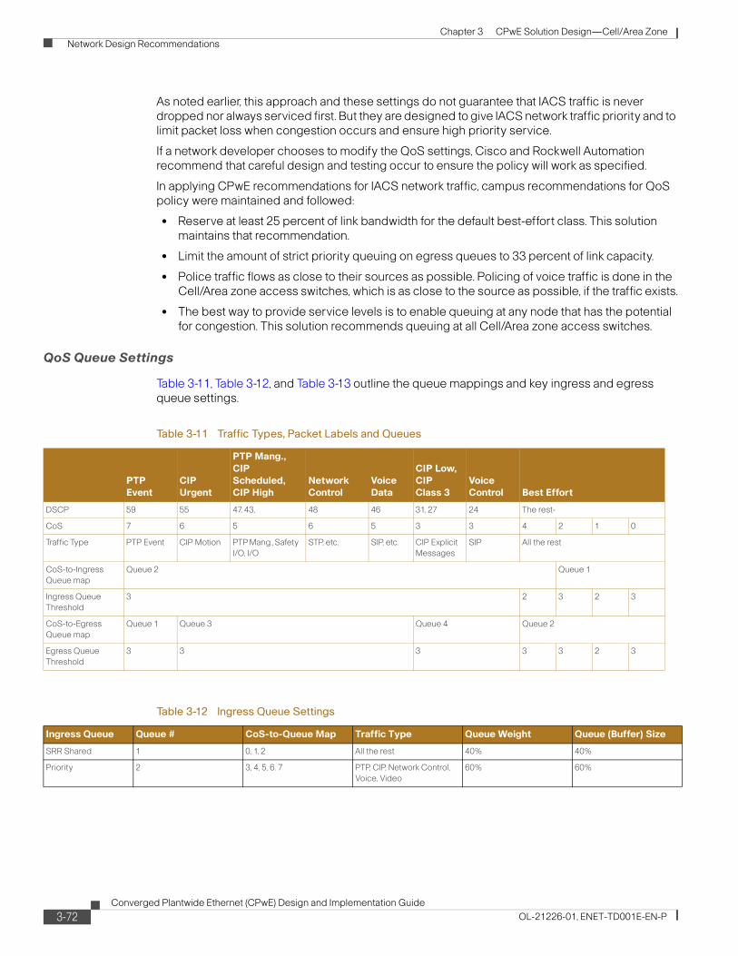
Chapter 3 CPwE Solution Design—Cell/Area Zone Network Design Recommendations
As noted earlier, this approach and these settings do not guarantee that IACS traffic is never dropped nor always serviced first. But they are designed to give IACS network traffic priority and to limit packet loss when congestion occurs and ensure high priority service.
If a network developer chooses to modify the QoS settings, Cisco and Rockwell Automation recommend that careful design and testing occur to ensure the policy will work as specified.
In applying CPwE recommendations for IACS network traffic, campus recommendations for QoS policy were maintained and followed:
• Reserve at least 25 percent of link bandwidth for the default best-effort class. This solution maintains that recommendation.
• Limit the amount of strict priority queuing on egress queues to 33 percent of link capacity.
• Police traffic flows as close to their sources as possible. Policing of voice traffic is done in the Cell/Area zone access switches, which is as close to the source as possible, if the traffic exists.
• The best way to provide service levels is to enable queuing at any node that has the potential for congestion. This solution recommends queuing at all Cell/Area zone access switches.
QoS Queue Settings
Table 3-11, Table 3-12, and Table 3-13 outline the queue mappings and key ingress and egress queue settings.
Table 3-11 Traffic Types, Packet Labels and Queues
PTP Event
CIP Urgent
PTP Mang., CIP Scheduled, CIP High
Network Control
Voice Data
CIP Low, CIP Class 3
Voice Control Best Effort
DSCP 59 55 47, 43, 48 46 31, 27 24 The rest-
CoS 7 6 5 6 5 3 3 4 2 1 0
Traffic Type PTP Event CIP Motion PTP Mang., Safety I/O, I/O
STP, etc. SIP, etc. CIP Explicit Messages
SIP All the rest
CoS-to-Ingress Queue map
Queue 2 Queue 1
Ingress Queue Threshold
3 2 3 2 3
CoS-to-Egress Queue map
Queue 1 Queue 3 Queue 4 Queue 2
Egress Queue Threshold
3 3 3 3 3 2 3
Table 3-12 Ingress Queue Settings
Ingress Queue Queue # CoS-to-Queue Map Traffic Type Queue Weight Queue (Buffer) Size
SRR Shared 1 0, 1, 2 All the rest 40% 40%
Priority 2 3, 4, 5, 6. 7 PTP, CIP, Network Control, Voice, Video
60% 60%
3-72Converged Plantwide Ethernet (CPwE) Design and Implementation Guide
OL-21226-01, ENET-TD001E-EN-P

Chapter 3 CPwE Solution Design—Cell/Area Zone Network Design Recommendations
SecurityThis section covers security design considerations for the Cell/Area zone. An overall security approach is presented in Chapter 5, “Implementing and Configuring the Cell/Area Zone.” Much of the security approach and recommendations are based on the Cisco Secure Architecture for Enterprise (SAFE). This solution applies the security recommendations specific to the Cell/Area zone. The following topics are covered in this section:
• Network Infrastructure Device Access
• Resiliency and Survivability
• Network Telemetry
• Other Cell/Area Zone Security Best Practices
• IACS Network Device Protection
Network Infrastructure Device Access
This subsection covers the following key topics around accessing the network infrastructure and industrial Ethernet switches in the Cell/Area zone:
• Port Security
• Set and Protect Local Passwords
• Implement Notification Banners
• Secure Administrative Access
Table 3-13 Egress Queue Settings
Egress Queue Queue # CoS-to-Queue Map Traffic Type Queue WeightQueue Size for Gb ports
Queue Size for 10/100 ports
Priority 1 7 PTP Event 1 10 10
SRR Shared 2 0, 1, 2, 4 All the rest 19 25 25
SRR Shared 3 5, 6 PTP Management, CIP Implicit I/O, Network Control & Voice data
40 40 40
SRR Shared 4 3 CIP Explicit Messages 40 25 25
3-73Converged Plantwide Ethernet (CPwE) Design and Implementation Guide
OL-21226-01, ENET-TD001E-EN-P

Chapter 3 CPwE Solution Design—Cell/Area Zone Network Design Recommendations
Port Security
Access to the network starts with physically accessing ports on switches. There are a number of techniques to limit the ability to access the network.
First, network access cannot be achieved if the network devices are physically secure with limited access. Placing the industrial Ethernet switches in locked rooms, cabinets, or even by buying port locks to close unused ports on a switch are all recommended best practices by Cisco and Rockwell Automation. Further, industrial Ethernet switches themselves can be configured to secure their ports from unknown access or miss-use. Switch port security limits the access to the network by unknown devices and limits the number of devices or MAC addresses on any network port. Port security builds a list of secure MAC addresses in one of two following ways, configurable on a per-interface basis:
• Dynamic learning of MAC addresses—Defines a maximum number of MAC addresses that will be learnt and permitted on a port. Useful for dynamic environments, such as at the access edge.
• Static configuration of MAC addresses—Defines the static MAC addresses permitted on a port. Useful for static environments, such as a server farm, a lobby, or a Demilitarized Network (DMZ).
Although some implementers may consider static MAC address configurations per-port for environments that need very high security, this method requires significant maintenance work where ports may need modification by network experts to perform normal maintenance tasks such as replacing a failed device. Therefore, Cisco and Rockwell Automation recommend application of the dynamic learning to limit the number devices that can access a port. This allows, for example, only one MAC address to access an IACS network port on the industrial Ethernet switch.
The Error Disable feature helps protect the switch and therefore the network from certain error conditions, for example when the number of MAC addresses on a port is exceeded. When the error condition is discovered, the interface is put into the error disable state and does not pass traffic. Cisco and Rockwell Automation recommend that the errdisable recovery interval seconds global configuration command be used to restore the port. This command will periodically check to see if the error condition still exists on the interface. The interface will automatically be enabled when the error condition has cleared.
Additionally, Cisco and Rockwell Automation recommend that all unused ports be disabled and only enabled when required.
Set and Protect Local Passwords
Global password encryption, local user-password encryption, and enable secret are features available in the industrial Ethernet switches to help secure locally stored sensitive information. Cisco and Rockwell Automation recommend the following:
• Enable automatic password encryption. Once configured, all passwords are encrypted automatically, including passwords of locally defined users.
• Define a local enable password using the enable secret global command.
• Define a line password with the password line command for each line you plan to use to administer the system.
In many enterprise environments, Authentication, Authorization and Accounting (AAA) is the method for access control to network infrastructure. This framework may be implemented for highly secure environments, but this method is more operationally challenging than the security
3-74Converged Plantwide Ethernet (CPwE) Design and Implementation Guide
OL-21226-01, ENET-TD001E-EN-P
Chapter 3 CPwE Solution Design—Cell/Area Zone Network Design Recommendations
requirements call for. If used though, Cisco and Rockwell Automation recommends TACACS+ (vs. RADIUS) when it comes to device administration. TACACS+ supports command authorization, allowing the control of which command can be executed on a device and which cannot.
Implement Notification Banners
Cisco and Rockwell Automation recommend that a legal notification banner login is presented on all interactive sessions to ensure that users are notified of the security policy being enforced and to which they are subject.
Secure Administrative Access
Cisco and Rockwell Automation and recommend the following best practices for securing administrative access:
• Enable SSH1 access when available rather than the unsecured Telnet. Use at a minimum 768-bit modulus size. This feature requires AAA or local accounts as specified in industrial Ethernet switch configuration guidelines (http://www.cisco.com/en/US/docs/switches/lan/cisco_ie3000/software/release/12.2_50_se/configuration/guide/swauthen.html#wp1227177).
• Avoid HTTP access. If possible use HTTPS instead of clear-text HTTP.
• Per-used line, explicitly define the protocols allowed for incoming and outgoing sessions. Restricting outgoing sessions prevent the system from being used as a staging host for other attacks.
• Set idle and session timeouts—Set idle and session timeouts in every used line. Enable TCP keepalives to detect and close hung sessions.
• Log and account for all access.
Resiliency and Survivability
This subsection presents the following collection of best practices destined to preserve the resiliency and survivability of switches and network services, helping the network and the IACS maintain availability even during the execution of an attack:
• Disable Unnecessary Services
• Port Security (as discussed previously)
• Redundancy
1. SSH and SNMP v3 require the cryptographic (K9) version of IOS on the Cisco IE 3000 and Allen-Bradley Stratix 8000 industrial Ethernet switches. Some cryptographic features are subject to additional export and contract restrictions. For more information about export trade restrictions, see http://www.cisco.com/web/about/doing_business/legal/global_export_trade/index.html for the IE 3000 or contact your Rockwell Automation sales representative or distributor for details for the Stratix 8000.
3-75Converged Plantwide Ethernet (CPwE) Design and Implementation Guide
OL-21226-01, ENET-TD001E-EN-P

Chapter 3 CPwE Solution Design—Cell/Area Zone Network Design Recommendations
Disable Unnecessary Services
Switches come out of the box with a list of services turned on that are considered appropriate for most network environments.
Disabling these unnecessary services has two benefits: it helps preserve system resources and eliminates the potential of security exploits on the disabled services.
Cisco and Rockwell Automation recommend the following best practices:
• Global services disabled by default—Unless explicitly needed, ensure finger, identification (identd), and TCP and UPD small servers remain disabled on all routers and switches.
• Global services enabled by default—Unless explicitly needed, BOOTP, IP source routing, and PAD services should be disabled globally on all routers.
• IP directed broadcast—Ensure directed broadcasts remain disabled on all interfaces except those required for access by RSLinx Data Servers to browse for known or available IACS EtherNet/IP devices.
• When to disable CDP—Disable CDP on interfaces where the service may represent a risk; for example, on external interfaces such as those at the Internet edge, and data-only ports at the campus and branch access.
• Access ports—Unless required disable MOP, IP redirects, and Proxy ARP on all access ports.
Redundancy
Networks are built out of numerous hardware and software components that may fail or that may be subject to attacks. Implementing redundant designs helps eliminate single points-of-failure, improving the availability of the network and making it more resistant to attacks. In the Cell/Area zone, there is a limit to how much redundancy can be implemented as most IACS network devices have only a single network interface.
The CPwE architecture is built with a wide range of options for redundancy:
• Backup and redundant uplink interfaces
• Element redundancy—Use of stacked or redundant switches in the distribution layer
• Standby devices— Active-standby and active-active failover is recommended for distribution layer in the case stacking is not an option.
• Topological redundancy—Designs built with redundant paths at both network and data-link layers. See “Topology Options and Media Considerations” section on page 3-21.
Network Telemetry
Telemetry is a word used in a number of contexts, and in this case it is used in both IT and IACS, with different connotations. This section covers the concept of network telemetry or the capability of automatically transmitting or retrieving data about the network infrastructure status and processing that information at a remote server or device. In other words, collecting and analyzing network infrastructure operational data.
In order to operate and ensure availability of a network, it is critical to have visibility and awareness into what is occurring on the network at any given time. Network telemetry offers extensive and useful detection capabilities that can be coupled with dedicated analysis systems to collect, trend, and correlate observed activity.
This subsection covers the following
3-76Converged Plantwide Ethernet (CPwE) Design and Implementation Guide
OL-21226-01, ENET-TD001E-EN-P
Chapter 3 CPwE Solution Design—Cell/Area Zone Network Design Recommendations
• Time Synchronization
• Local Device Statistics
• Network Device Status Information
• System Logging
• Simple Network Management Protocol (SNMP)
Time Synchronization
Time synchronization is critical for event analysis and correlation, thus enabling Network Time Protocol (NTP) or Precision Time Protocol (PTP) on all infrastructure components is a fundamental requirement. Timestamps are contained on system messages and within system logs. Timestamps are needed to properly analyze and understand events that occur within the network infrastructure by providing time sequence. Cisco and Rockwell Automation recommends a time synchronization function is installed in the Manufacturing zone extending to the Cell/Area zone.
For more on implementing NTP, see Time synchronization in the Cisco SAFE Reference Guide or the TP Best Practice whitepaper (http://www.cisco.com/en/US/tech/tk869/tk769/technologies_white_paper09186a0080117070.shtml). Design and implementation of PTP is not covered in the scope of this CPwE DIG.
Cisco and Rockwell Automation recommend that a time synchronization service is implemented in the Manufacturing zone and extends to the Cell/Area zones.
Local Device Statistics
Local device statistics are the most basic and ubiquitous form of telemetry available. They provide baseline information such as per-interface throughput and bandwidth statistics, enabled features and global per-protocol traffic statistics. Key statistics to track include:
• Per-interface statistics which include throughput Packets Per Second (PPS) and Bandwidth Per Second (BPS) information.
• Per-interface IP features provides information about the IP features configured on an interface on Layer-3 switches and routers.
• Global IP statistics, including per-protocol counts for ICMP, TCP, UDP, and multicast traffic on Layer-3 switches and routers.
For more information on the statistics and information to track on industrial Ethernet switches, see the “Local Device Statistics” section in “Chapter 2, Network Foundation Protection” of the Cisco SAFE Reference Guide at the following URL:
http://www.cisco.com/en/US/docs/solutions/Enterprise/Security/SAFE_RG/chap2.html
Cisco and Rockwell Automation recommend that the local device statistics is regularly monitored.
Network Device Status Information
The Industrial Ethernet switches themselves provide a wide range of statistics and alarms on their own status. Key information includes:
• Memory, CPU, and processes providing a basic overview of the switch health and current state
• Memory and CPU threshold notifications to alarm when the state of the switch is out of normal ranges and action may be needed
3-77Converged Plantwide Ethernet (CPwE) Design and Implementation Guide
OL-21226-01, ENET-TD001E-EN-P

Chapter 3 CPwE Solution Design—Cell/Area Zone Network Design Recommendations
For more information on the statistics and information to track on industrial Ethernet switches, see the “System Status Information” section in “Chapter 2, Network Foundation Protection of the Cisco SAFE Reference Guide at the following URL:
http://www.cisco.com/en/US/docs/solutions/Enterprise/Security/SAFE_RG/chap2.html
Cisco and Rockwell Automation recommend that the network device status information is regularly monitored and acted upon when thresholds are exceeded.
System Logging
Syslog provides invaluable operational information, including system status, traffic statistics, and device access information. For this reason, syslog is recommended on all network devices.
Follow these practices when enabling syslog:
Step 1 Enable timestamps for debugging and logging messages. Adding timestamps to messages facilitates analysis and correlation.
Step 2 Enable system message logging to a local buffer. This allows accessing the logging information directly from the router or switch in case of communication failure with the syslog server. It is important to note that local buffers are circular in nature so that newer messages overwrite older messages after the buffer is filled.
Step 3 Set the severity level of messages to be logged. Messages at or numerically lower than the specified level are logged. With respect to the severity level, the more information is logged the better; therefore, logging messages of all severity levels would be ideal. However, this may result in an overwhelming volume of messages. A good practice is to enable more detailed logging on critical systems or systems that may be more accessible to external or remote users, and only log critical alerts for the rest of the infrastructure.
Step 4 Set the source IP address of syslog messages to the address of an administrative loopback interface or, if in use the out-of-band interface.
Step 5 Disable the logging of messages to the console. This helps keep the console free of messages.
For more information on the statistics and information to track on industrial Ethernet switches, refer to the “System Logging section in “Chapter 2, Network Foundation Protection of the Cisco SAFE Reference Guide at the following URL:
http://www.cisco.com/en/US/docs/solutions/Enterprise/Security/SAFE_RG/chap2.html
Also refer to the Best Practices for IOS Switches at the following URL: (http://www.cisco.com/en/US/products/hw/switches/ps700/products_white_paper09186a00801b49a4.shtml#cg22).
Simple Network Management Protocol (SNMP)
SNMP is the protocol used by most IT organizations to monitor and manage a network infrastructure, servers and even in some cases end-devices. SNMP provides a standardized framework and a common language used for the monitoring and management of devices in a network. Although there are other protocols and means to perform the basic network management, SNMP is the most sophisticated and developed standardized protocol for this explicit purpose. Cisco and Rockwell Automation consider it a best practice to use tools and applications that use SNMP and therefore it should be enabled throughout the network infrastructure.
3-78Converged Plantwide Ethernet (CPwE) Design and Implementation Guide
OL-21226-01, ENET-TD001E-EN-P

Chapter 3 CPwE Solution Design—Cell/Area Zone Network Design Recommendations
In case SNMP access is not required, make sure it is disabled. The no snmp-server command disables all running versions of SNMP (SNMPv1, SNMPv2C, and SNMPv3) on the device.
When SNMP is required, follow these best practices:
Step 1 Restrict what systems can access the SNMP agent running on the router or switch. Be as specific as possible, for instance, only permitting access from the SNMP management stations.
Step 2 If using SNMPv31 (recommended), enforce an SNMP view that restricts the download of full IP routing and ARP tables.
Step 3 If SNMPv3 is supported, enable only SNMP v3 and with the maximum security level supported by the SNMP managers, using encrypted communication (priv) where feasible. The engine ID of an SNMP v3 SNMP manager is required in order to enable SNMPv3.
Step 4 Set the source IP address for SNMP traps to the address used on the administrative loopback interface of out-of-band interface.
For more on SNMP configuration see Best Practices for IOS Switches (http://www.cisco.com/en/US/products/hw/switches/ps700/products_white_paper09186a00801b49a4.shtml#cg23)
Other Cell/Area Zone Security Best Practices
This section covers other security best practices relevant to the Cell/Area zone, including the following:
• Restrict Broadcast Domains
• STP Security
• VLAN Best Practices
• DHCP Protection
• ARP Spoofing Protection
• Traffic Storm Protection
Restrict Broadcast Domains
By definition, LAN switches are responsible for forwarding unknown frames, multicast frames and broadcast frames throughout the LAN segment, forming a broadcast domain. While broadcast domains facilitate Layer-2 connectivity between systems on a LAN segment, designing networks with unnecessarily large broadcast domains has potential drawbacks.
First, in large networks, the flooding of unknown, multicast and broadcast frames may degrade performance, even to the point of breaking connectivity. In addition, a broadcast domain defines a failure domain, whereby all systems and switches on the same LAN segment suffer during a failure. Therefore the larger the broadcast domain the bigger the impact of a failure. Finally, larger broadcast domains increase the chances of security incidents.
To avoid the challenges described above, it is a good practice to segment broadcast domains into multiple IP subnets or VLANs using a hierarchical, topologies or functional design. Cisco and Rockwell Automation recommend applying VLANs to restrict broadcast domains. See “VLAN Design” section on page 3-38 for more information.
1. SSH and SNMP v3 require the cryptographic (K9) version of IOS on the Cisco IE 3000 and Allen-Bradley Stratix 8000 industrial Ethernet switches. Some cryptographic features are subject to additional export and contract restrictions. For more information about export trade restrictions, see http://www.cisco.com/web/about/doing_business/legal/global_export_trade/index.html for the IE 3000 or contact your Rockwell Automation sales representative or distributor for details for the Stratix 8000.
3-79Converged Plantwide Ethernet (CPwE) Design and Implementation Guide
OL-21226-01, ENET-TD001E-EN-P

Chapter 3 CPwE Solution Design—Cell/Area Zone Network Design Recommendations
STP Security
STP is a key aspect of this solution and is typically found in network infrastructures, often even if other resiliency protocols are in effect. There are a number of features designed to protect the functioning of this protocol. Cisco and Rockwell Automation recommend the following:
• Disable VLAN dynamic trunk negotiation trunking on IACS ports
• Use Rapid Per-VLAN Spanning Tree (RPVST+) or MSTP when using STP for resiliency or loop protection
• Configure BPDU Guard on host ports
• Configure BPDU Filter on host ports
• Configure STP Root Guard on the STP root (normally the distribution switch)
• Disable unused ports and put them into an unused VLAN
• Enable traffic storm control (see below)
VLAN Best Practices
VLAN hopping is an attack vector that provides a client with unauthorized access to other VLANs on a switch. This type of attack can be easily mitigated by applying the following best common practices recommended by Cisco and Rockwell Automation:
• Always use a dedicated native VLAN ID for all trunk ports
• Disable all unused ports and put them in an unused VLAN
• Do not use VLAN 1 for anything
• Configure all IACS-facing ports as non-trunking (DTP off)
• Explicitly configure trunking on infrastructure ports
• Set the default port status to disable
DHCP Protection
IP address allocation is an important network service that must be protected. The IP address allocation is described in the “IP Addressing” section on page 4-38. DHCP or BOOTP are most likely used at some point to give a device an IP Address at points during it’s lifetime in the IACS network. Therefore, protecting that service is an important consideration for the Cell/Area zone protection.
DHCP protection is critical to ensure that a client on a Cell/Area zone port is not able to spoof or accidentally bring up a DHCP server, nor exhaust the entire DHCP address space by using a sophisticated DHCP starvation attack. Both these attacks are addressed with the Cisco IOS DHCP snooping feature that performs two key functions to address these attacks:
• Rogue DHCP Server Protection—If reserved DHCP server responses are received on an untrusted port (such as an access port), the interface is shutdown.
• DHCP Starvation Protection—Validates that the source MAC address in the DHCP payload on an untrusted (access) interface matches the source MAC address registered on that interface.
DHCP snooping is enabled on a per-VLAN basis and all interfaces in that VLAN are untrusted by default. Consequently, an interface hosting a DHCP server must be explicitly defined as trusted.
Rockwell Automation and Cisco recommend DHCP snooping is enabled in Cell/Area zone on a per-VLAN basis and on all end-host ports.
3-80Converged Plantwide Ethernet (CPwE) Design and Implementation Guide
OL-21226-01, ENET-TD001E-EN-P

Chapter 3 CPwE Solution Design—Cell/Area Zone Network Design Recommendations
ARP Spoofing Protection
ARP spoofing protection ensures that a client on an access edge port is not able to perform a man-in-the-middle (MITM) attack by sending a gratuitous ARP that presents its MAC address as that associated with a different IP address, such as that of the default gateway. This attack is addressed with the Cisco IOS Dynamic ARP Inspection (DAI) feature that validates that the source MAC and IP address in an ARP packet received on an untrusted interface matches the source MAC and IP address registered on that interface.
DAI is enabled on a per-VLAN basis and all interfaces in that VLAN are untrusted by default. Consequently, a device that does not use DHCP, such as the default gateway, ARP inspection must be bypassed by either explicitly defining the interface it is connected to as trusted, or creating an ARP inspection ACL to permit the source MAC and IP address of that device.
Cisco and Rockwell Automation recommend enabling DAI on IACS network VLANs and end-host ports. DAI may interfere with some IACS controller redundancy schemas using EtherNet/IP and should not be used. Controller redundancy is not covered in this version of the CPwE DIG.
Traffic Storm Protection
When a large amount of broadcast (and/or multicast) packets congest a network, the event is referred to as a broadcast storm. A storm occurs when broadcast or multicast packets flood the subnet, creating excessive traffic and degrading network performance. Storm control prevents LAN interfaces from being disrupted by these broadcast and multicast storms. Errors in the protocol-stack implementation, mistakes in network configurations, or users issuing a denial-of-service (DoS) attack can cause a storm.
Storm control (or traffic suppression) monitors packets passing from an interface to the switching bus and determines if the packet is unicast, multicast, or broadcast. The switch counts the number of packets of a specified type received within the 1-second time interval and compares the measurement with a predefined suppression-level threshold. Once the suppression-level threshold is reached, the port blocks traffic until the traffic falls below the threshold level.
Cisco and Rockwell Automation recommend storm control is enabled on end-host ports.
Storm control uses one of the following methods to measure traffic activity:
• Bandwidth as a percentage of the total available bandwidth of the port that can be used by the broadcast, multicast, or unicast traffic.
• Traffic rate in packets per second at which broadcast, multicast, or unicast packets are received.
• Traffic rate in bits per second at which broadcast, multicast, or unicast packets are received.
• Traffic rate in packets per second and for small frames. This feature is enabled globally. The threshold for small frames is configured for each interface. (Cisco IOS Release 12.2(44)SE or later).
With each method, the port blocks traffic when the rising threshold is reached. The port remains blocked until the traffic rate drops below the falling threshold (if one is specified) and then resumes normal forwarding. If the falling suppression level is not specified, the switch blocks all traffic until the traffic rate drops below the rising suppression level. In general, the higher the level, the less effective the protection against broadcast storms.
For Cell/Area zone devices, Cisco and Rockwell Automation recommend applying broadcast storm controls. Multicast and unicast controls are available, but Cisco and Rockwell do not recommend setting these unless the implementer performs sufficient testing to avoid causing unintended outages. The IE 3000 (Cisco version) of the switch has default configuration of 3 percent of port bandwidth set as the rising broadcast threshold and 1 percent as the falling threshold. These are
3-81Converged Plantwide Ethernet (CPwE) Design and Implementation Guide
OL-21226-01, ENET-TD001E-EN-P
Chapter 3 CPwE Solution Design—Cell/Area Zone Network Design Recommendations
deemed to be sufficient to stop many broadcast storms, yet not cause unnecessary disruptions in typical plant networks. In our testing, these thresholds did not cause issues. If these settings are changed, sufficient testing should occur to avoid causing unintended outages.
The default action when storm control thresholds are reached is to drop traffic until the falling threshold is reached. Cisco and Rockwell recommend maintaining this setting. The settings allow for shutting down the port when the rising threshold is reached, in which case the port is set to error disable status, and must be manually restored (no shut) or error-disable settings set to restore the port.
In addition, the settings allow for notification when storm control thresholds are reached. Cisco and Rockwell Automation recommend that implementers use the notification capabilities to monitor when storm controls are reached so as action can be taken. SNMP and the CIP object can be used to monitor the storm control thresholds.
IACS Network Device Protection
Protecting IACS network assets requires a defense-in-depth security approach. This concept was introduced in Chapter 1, “Converged Plantwide Ethernet Overview.” This approach uses multiple layers of defense (physical and electronic) at separate levels of the CPwE logical framework by applying policies and procedures that address different types of threats. No single technology or methodology can fully secure IACS networks.
In addition to the defense-in-depth layers already discussed, securing IACS network assets require the following:
• Physical security—This limits physical access of areas, control panels, IACS devices, cabling and the control rooms and other locations to authorized personnel as well as escorting and tracking visitors and partners.
• Computer hardening—This includes patch management and antivirus software as well as removal of unused applications, protocols and services.
• Application security—This contains authentication, authorization and audit software such as FactoryTalk Security for IACS applications.
• Controller hardening—This handles change management and restrictive access.
Controller Hardening
Secure Rockwell Automation Logix™ Programmable Automation Controllers (PAC) by physical procedures, electronic design, authentication and authorization software, and change management with disaster recovery software. Best practices and general recommendations include the following:
• Physical procedure—This restricts control panel access only to authorized personnel. This can accomplished by implementing access procedures or locking the panels. Switching the PAC key switch to “RUN” helps to prevent remote configuration changes. Remote configuration changes would then require a physical key change at the PAC by onsite plant floor personnel. Unauthorized access (intentional or unintentional) would not occur until the PAC key switch is changed.
• Electronic design—Implementing the PAC CPU Lock feature denies front port access to the PAC, which prevents configuration changes.
3-82Converged Plantwide Ethernet (CPwE) Design and Implementation Guide
OL-21226-01, ENET-TD001E-EN-P

Chapter 3 CPwE Solution Design—Cell/Area Zone Network Design Recommendations
• Authentication, authorization and audit by implementing FactoryTalk® Security—Authentication verifies a user’s identity and whether service requests originate with that user. Authorization verifies a user’s request to access a feature or PAC against a set of defined access permissions.
• Change management with disaster recovery—Use FactoryTalk® AssetCentre software to continuously monitor PAC assets with automatic version control, disaster recovery and backup, device configuration verification and real-time auditing of user actions.
Computer Hardening
For computing assets within the Cell/Area zone, implement IT best practices applied to enterprise computers. Some best practices and general recommendations include the following:
• Keep computers up-to-date on service packs and hot fixes, but disable automatic updates. Additionally, network developers should test patches before implementing them as well as schedule patching and regular network maintenance during manufacturing downtime.
• Deploy and maintain antivirus and antispyware software, but disable automatic updates and automatic scanning. Test definition updates before implementing them as well as schedule manually initiated scanning during manufacturing downtime since antispyware scanning can disrupt real-time operations. Automatic antivirus and antispyware scanning has caused data loss and downtime at some manufacturing facilities.
• Prohibit direct internet access. Implementing a Demilitarized Zone (DMZ) provides a barrier between the Manufacturing and Enterprise zones, but allows IACS applications to securely share data and services. All network traffic from either side of the DMZ terminates in the DMZ. No traffic traverses the DMZ, meaning that traffic does not directly travel between the Enterprise and Manufacturing zones.
• Implement a separate Active Directory domain/forest for the Manufacturing zone. This helps ensure availability to manufacturing assets if connectivity to the Enterprise zone is disrupted.
• Implement the following password policy settings:
– Enforce password history
– Maximum password age
– Minimum password length
– Complex password requirements
• Disable the guest account on clients and servers.
• Require that the built-in administrator account uses a complex password, has been renamed and has removed its default account description.
• Develop, and then deploy, backup and disaster recovery policies and procedures. Test backups on a regular schedule.
• Implement a change management system to archive network, controller and computer assets (e.g., clients, servers and applications).
• Use Control+Alt+Delete, along with a unique user name and password to log in.
• Protect unnecessary or infrequently used USB ports, parallel and serial interfaces to prevent unauthorized hardware additions (modems, printers, USB devices, etc.).
• Uninstall the unused Windows® components, protocols and services not necessary to operate the manufacturing system.
3-83Converged Plantwide Ethernet (CPwE) Design and Implementation Guide
OL-21226-01, ENET-TD001E-EN-P

Chapter 3 CPwE Solution Design—Cell/Area Zone Network Design Recommendations
ScalabilityIt is considered a best practice to maintain smaller broadcast domains, subnets and VLANs for a variety of reasons. The performance of the network simply is easier to manage. Cisco and Rockwell Automation recommend that a design goal is to maintain smaller versus larger Cell/Area zones. The key reasons include the following:
• Improved network and end-device performance as broadcast traffic is contained to smaller set of devices.
• Increased security by limiting the impact of various types of security risks/threat.
• Manufacturers sometimes do not have the flexibility to maintain this objective and often inquire about the limitations involved in creating larger Cell/Area zone networks. Cisco and Rockwell Automation cannot give direct recommendations on the size of the Cell/Area zone, in terms of the number of switches or end-devices. IACS applications vary greatly in their latency, jitter and traffic generation requirements and characteristics. These requirements and characteristics have to be considered when designing the network.
For the purpose of testing various configurations, Cisco and Rockwell Automation chose to test configurations with up to 16 industrial Ethernet switches and to simulate up to 400 end-devices determined that this was a reasonable upper end for most deployments, although it is understood that applications exist where these parameters will be exceeded. These test results and test descriptions, contained herein as referential guidance, can be used to estimate the performance of Cell/Area networks of different sizes.
This section highlights the following considerations for the scalability of a Cell/Area network:
• Scalability limitations of the relevant network resiliency protocols
• Limitations on the number of multicast groups industrial Ethernet switches can manage.
• Impact of the number of switches on the IACS network deterministic nature
• Impact of the number of switches on the network convergence
Scalability and Network Resiliency Protocols
The size of the Spanning Tree managed topology is limited by the age of the BPDUs. STP specifies a “max_age” that determines when the BPDUs age would time out. Switches receiving “aged” BPDUs simply block that port. Thus a ring of switches larger than the allowed by the max_age parameter would simply end up a split network with more than 1 STP root. By default in the industrial Ethernet switches, RPVST+ and MSTP are configured with settings to limit the diameter of the network at 20 switches. For RPVST+, the maximum-age of a BPDU can be set to 40, or essentially a diameter of 40 switches. In MSTP, the max-hop setting has a range of up to 255, at which point MSTP regions must be in place, but by nature the network will have some segmentation.
Adjusting the STP defaults should be done with extreme caution and with sufficient testing. Cisco and Rockwell Automation do not recommend changing STP defaults.
EtherChannel and Flex Links work between two switches/routers. Although they can operate with any number of end-devices and VLANs supported by the switches used, by their nature, they are effectively limited to redundant star configurations. Redundant star configurations can efficiently scale based on limitations of the distribution switches or routers. There are no specific relevant limitations to communicate for Cell/Area zone designs in regards to the redundant star topology.
3-84Converged Plantwide Ethernet (CPwE) Design and Implementation Guide
OL-21226-01, ENET-TD001E-EN-P

Chapter 3 CPwE Solution Design—Cell/Area Zone Network Design Recommendations
Limitations on the Number of Multicast Groups
The industrial Ethernet switches in the CPwE design have a limit of 255 multicast groups in the IGMP snooping function. If a switch received multicast packets for more than 255 multicast groups, it simply starts broadcasting those multicast groups. In CPwE testing, when this situation occurred, it was found that IACS network applications became unstable with connections dropping consistently.
The Layer-3 Cisco platforms (including the Catalyst 3750) typically support up to 1000 or more multicast groups. This may be a consideration when consolidating a number of Cell/Area zones into a distribution switch.
Refer to the “Multicast Management” section on page 3-54 for more on multicast traffic.
Impact of the Number of Switches on the IACS Network Deterministic Nature
In the real-time requirements, CPwE outlined requirement to provide information on how the number of industrial Ethernet switches in the IACS network may impact the deterministic nature of the IACS network. CPwE testing applied a screw-to-screw test to show the impact of the number of industrial Ethernet switches had on the overall IACS network determinism. This test is described in more detail in Chapter 7, “Testing the CPwE Solution,” but it essentially measures how fast a digital input signal is received from a digital output via an EtherNet/IP I/O device to a controller. The test was designed to show the application level latency and jitter (versus strictly the network latency). In the test, the distributed I/O was configured with a 10ms RPI. Each test run collected 300,000 samples. In this test case, the EtherNet/IP traffic passed through two industrial Ethernet switches. Figure 3-29 shows the application level latency and jitter as measured by the IACS application.
Figure 3-29 Application Latency and Jitter
3-85Converged Plantwide Ethernet (CPwE) Design and Implementation Guide
OL-21226-01, ENET-TD001E-EN-P

Chapter 3 CPwE Solution Design—Cell/Area Zone Network Design Recommendations
Cisco and Rockwell Automation executed the test under a variety of conditions to show how the number of industrial Ethernet switches impacted application level latency and jitter. Figure 3-30 shows an example of the same test as that shown in Figure 3-29, except that a network break was introduced before starting the test run that ensured the EtherNet/IP traffic traversed the whole ring, or nine switches, including the 3750-stack.
Figure 3-30 Application Latency and Jitter
The various test runs of the screw-to-screw tests are summarized in Table 3-14. The table shows that the latency and jitter due to additional industrial Ethernet switches are relatively insignificant compared to the overall IACS network application latency and jitter. The additional latency per-switch hop was approximately 10 μs in the test cases.
Table 3-14 Screw-to-Screw Test Results
Short-path Long-pathAnalysis
Test Suite
No. of hops
Avg. (ms)
Min (ms) Max (ms) No. of hops
Avg. (ms)
Min (ms) Max (ms) Delta (ms) Latency per hop (ms)
RMC8 2 13.045 2.175 25.100 9 13.111 2.200 25.025 0.066 0.009
2 13.143 2.225 25.200 9 13.183 2.275 25.976 0.040 0.006
RMC16 2 13.035 2.175 24.824 17 13.185 2.175 24.825 0.150 0.010
2 13.136 2.250 24.924 17 13.303 2.250 25.325 0.167 0.011
RMF8 2 13.036 2.175 24.849 9 13.108 2.175 60.076 0.072 0.010
2 13.148 2.225 25.151 9 13.220 2.250 26.300 0.072 0.010
SMC8 3 13.044 2.225 24.825
3 13.175 2.275 24.900 3 13.183 2.275 25.975
SMF8 3 13.036 2.200 24.825
SEC8 3 13.045 2.200 24.826 3 13.035 2.200 24.849
SEF8 3 13.061 2.172 24.825 3 13.134 2.225 26.199
3 13.165 2.251 24.899 3 13.169 2.250 25.175
3-86Converged Plantwide Ethernet (CPwE) Design and Implementation Guide
OL-21226-01, ENET-TD001E-EN-P

Chapter 3 CPwE Solution Design—Cell/Area Zone Network Design Recommendations
Impact of the Number of Switches on Network Convergence
In the requirements outlined earlier, the CPwE solution describes the need to understand the impact the number of industrial Ethernet switches in the Cell/Area zone has on IACS network resiliency and IACS network convergence. This applies only to Ring topologies. In Redundant Star topologies, the loss of an uplink connection only impacts the communication to and from the affected switch. The number of hops between one device and another does not change due to a link-down or link-loss. This is confirmed in that there is no data loss to devices that are not using the impacted communication path. The network convergence stays roughly the same whether 1 or 20 access switches are involved in the Cell/Area zone.
For ring topologies though, any link-loss or break means that a blocked port must open and that all devices need to relearn their MAC and multicast addresses.
To measure this impact, Cisco and Rockwell Automation conducted a variety of test cases on ring topologies with 8 and 16 industrial Ethernet switches in the ring. The switches were interconnected with copper uplinks. The test results consistently showed that the network converged more slowly. When looking at the average maximum network convergence measured per test case, the 16 switch configuration converged 250 to 300 ms slower than the 8 ring configuration. The impact was more profound in the software shutdown, where the 16 switch configuration converged anywhere from 550ms to 800ms slower than the 8-switch configuration. Figure 3-31 and Figure 3-32 depict the key statistics from the test cases where a physical cable disruption and software disruptions are introduced. The trend is an increased network convergence.
Figure 3-31 Test Scenario where Physical Cable Disruption
3-87Converged Plantwide Ethernet (CPwE) Design and Implementation Guide
OL-21226-01, ENET-TD001E-EN-P

Chapter 3 CPwE Solution Design—Cell/Area Zone Network Design Recommendations
Figure 3-32 Test Scenario where Physical Software Disruption
Summary
To reiterate, Cisco and Rockwell Automation recommend smaller Cell/Area zones. However, if Cell/Area zones must be scaled, the following are some considerations:
• As a Cell/Area grows, it most directly impact the IACS network and device performance, network convergence times and overall risk. In properly configured IACS applications and networks, modern network infrastructure is more than suited to handle the amount of traffic generated by the IACS network applications. The IACS network end-devices tend to be more impacted by more network traffic in large Cell/Area zones as well as the network convergence times.
• If using STP, the default configuration for both MSTP and RPVST+ defines a 20-switch diameter for network configurations. That can be increased, but careful testing is recommended to verify the impact on network convergence.
• The industrial Ethernet switches support only 255 multicast groups in their IGMP snooping functions. The number of multicast groups is dependent on the number of IACS network devices and how the information flow is configured between those devices. The flooding of the multicast traffic of groups beyond the 255 limit had significant impact on the IACS network, where critical connections between the IACS network devices consistently shutdown, presumably due to IACS network device load. Larger Cell/Area VLANs may very well find this a constraint.
• The number of industrial Ethernet switches in a Cell/Area zone network did not have a significant impact on the overall IACS network latency and jitter.
• The number of industrial Ethernet switches in a Cell/Area zone network did have a significant impact on the IACS network convergence.
3-88Converged Plantwide Ethernet (CPwE) Design and Implementation Guide
OL-21226-01, ENET-TD001E-EN-P

Converged Plantwide Ethernet (CPwOL-21226-01, ENET-TD001E-EN-P
C H A P T E R 4
CPwE Solution Design—Manufacturing and Demilitarized ZonesOverview This chapter provides an overview and basic design considerations for the Manufacturing and Demilitarized zones of the CPwE architecture. This solution guide offers basic design and implementation guidance for these zones, with which Industrial Automation and Control Systems (IACS) networking personnel could design and deploy a basic implementation. Often, these zones are where Enterprise IT networking resources or hybrid Plant-IT resources are involved in the design, implementation, and maintenance. For more complex deployments, Cisco and Rockwell Automation recommend that either external resources or Enterprise IT networking experts are used for the design, implementation, and maintenance.
Manufacturing ZoneThe Manufacturing zone contains all IACS networks, devices, and controllers that are critical to controlling and monitoring plantwide operations. Hierarchically, the Manufacturing zone includes Site Manufacturing Operations and Control functions (Level 3) as well as multiple Cell/Area zones (Levels 0 to 2).
To preserve smooth plantwide operations and functioning of the IACS application and IACS network, this zone requires clear isolation and protection from the Enterprise zone via security devices within the Demilitarized zone (DMZ). This insulation not only enhances security segmentation between the Enterprise and Manufacturing zones, but may also represent an organization boundary where IT and manufacturing organizational responsibilities interface.
This approach permits the Manufacturing zone to function entirely on its own, irrespective of the connectivity status to the higher levels. A methodology and procedure should be deployed to buffer IACS data to and from the Enterprise zone in the event of DMZ connectivity disruption. As a best practice, Cisco and Rockwell Automation recommend that all manufacturing assets required for the operation of the Manufacturing zone should remain there. Assets include FactoryTalk as well as applications and services such as Active Directory, DNS, and WINS.
4-1E) Design and Implementation Guide

Chapter 4 CPwE Solution Design—Manufacturing and Demilitarized Zones Overview
Level 3, Site Manufacturing Operation and Control, has a dedicated Level 3 IACS network within the Manufacturing zone and contains the IACS software, such FactoryTalk. Cisco and Rockwell Automation recommend assigning a unique IP subnet and virtual LAN (VLAN) to this Level 3 IACS network.
The FactoryTalk application servers connect to a dedicated multilayer access switch, which aggregates into the Layer-3 distribution switches. To provide redundant default gateways to the Cell/Area zones, use the Cisco Catalyst 3750 StackWise Layer-3 distribution switches. If standalone distribution switches are used, use Gateway Load Balancing Protocol (GLBP) or Hot-Standby Routing Protocol (HSRP) between the distribution switches. Standalone distribution switches are not addressed in this version of the Design and Implementation Guide (DIG). These protocols provide Layer 3 failover and load-balancing capabilities that are important to ensure communications between the Level 3 IACS network and the Cell/Area IACS network in the event of network disruption. FactoryTalk application-server redundancy is not addressed in CPwE 2.0.
An example of software applications that would be deployed within the Level 3 IACS network includes the following:
• FactoryTalk Services Platform
– Directory
– Activation
– Security
– Diagnostics
– Audit
– Live Data
– Alarms and Events
• Application Servers
– Factory Talk View SE
– FactoryTalk AssetCentre
– FactoryTalk Historian
– FactoryTalk Transaction Manager
• Engineering Workstation
– RSLogix™ 5000/500/5
– RSNetWorx™
Key functions and features of the CPwE architecture for the Manufacturing zone include the following:
• Interconnecting the various Cell/Area IACS networks
• Interconnecting the Level 3 Site Manufacturing Systems
• Providing network management and security services to the Level 0 to 3 systems and devices
• Endpoint protection
The key Manufacturing zone design topics covered in this chapter include the following:
• Traffic flow
• Component selection
• Topology
4-2Converged Plantwide Ethernet (CPwE) Design and Implementation Guide
OL-21226-01, ENET-TD001E-EN-P
Chapter 4 CPwE Solution Design—Manufacturing and Demilitarized Zones Overview
• Routing
• High Availability and Network Resiliency
• IP addressing
• Security
• IACS Software, such as FactoryTalk, positioning within the Manufacturing zone
Multicast management is not included as a function in the Manufacturing zone. Although multicast traffic is routable traffic in many application types (video and voice), the most prevalent IACS network traffic applications ensure multicast traffic is contained to the Layer 2 network or subnet/VLAN with TTL=1. For the scope of this DIG, multicast traffic is constrained to the Cell/Area zone. IACS applications using routable multicast traffic or Precision Time Protocol (PTP) solutions are not yet common, but in the future will require design and implementation of multicast routing capabilities.
The Manufacturing zone is analogous to the core and distribution network hierarchy levels of the campus network architecture. This section refers to and includes many of the network recommendations from the following campus design guides:
• Overall Campus
http://www.cisco.com/en/US/solutions/ns340/ns414/ns742/ns815/landing_cOverall_design.html
• High Availability
http://www.cisco.com/en/US/solutions/ns340/ns414/ns742/ns815/landing_cHi_availability.html
Demilitarized ZoneIn the design of the industrial Ethernet network, one of the critical elements is to ensure the separation between the IACS network and the enterprise network. In terms of the Purdue Reference Model, this is the separation between Levels 0 to 3 and Levels 4 to 5. This separation is necessary because real-time availability and security are the critical elements for the traffic in the IACS network. The impact of downtime in an IACS network is much more costly than downtime of similar scale in an enterprise environment. The cost of capital, the loss of product and material, missed schedule, and the wasted time of plant personnel drive this very concrete impact on revenue and efficiency. Therefore, Cisco and Rockwell Automation recommend the deployment of plant firewalls and a DMZ between the Manufacturing and Enterprise zones to securely manage the traffic flow between these networks.
It is a requirement to share data and services between the Manufacturing and Enterprise zones. Many of the benefits of a converged manufacturing and enterprise network rely on real-time communication and transfer of data between these zones. Without plant firewalls and a DMZ, this sharing is not possible while maintaining the security of the IACS network and its IACS systems. The plant firewall:
• Enforces authentication of users trying to access data or services
• Strictly controls traffic flow
• Performs stateful packet inspection and intrusion detection/protection
• Provides security and network management support
• Terminates VPN sessions with external or internal users
4-3Converged Plantwide Ethernet (CPwE) Design and Implementation Guide
OL-21226-01, ENET-TD001E-EN-P

Chapter 4 CPwE Solution Design—Manufacturing and Demilitarized Zones Key Requirements and Considerations
• Provides Web-portal services to offer proxies services, such as remote desktop, to specific servers in the Manufacturing zone
DMZ offers a network on which to place data and services to be shared between the Enterprise and Manufacturing zones. The DMZ enables the principle of not allowing direct communication between the Manufacturing and Enterprise zones, while meeting the requirement to share data and services. With the deployment of a DMZ and plant firewall, attacks and issues that arise in one zone cannot easily affect the other zone. In fact, by temporarily disabling the DMZ and plant firewall, an IACS or IT network administrator can protect a zone from being attacked until the situation is resolved in the other zone.
The DMZ network design covers the following:
• DMZ components
• DMZ topology
• Firewall design and implementation considerations
Key Requirements and ConsiderationsThis section outlines the general requirements and considerations for the DMZ network and Manufacturing zone IACS networks. The requirements generally follow the requirements listed for the overall solution in Chapter 1, “Converged Plantwide Ethernet Overview.” An additional consideration of application and service composition was also added to highlight the need to identify what key network, security and application services will be replicated or located in the various zones.
Industrial CharacteristicsMost manufacturing facilities have environmentally controlled areas for certain types of applications and IT-related infrastructure. The Manufacturing and Demilitarized zone applications and systems typically reside in these environments. This suggests that the environmental requirements of the Cell/Area IACS network typically do not apply to the Manufacturing and Demilitarized zone network infrastructure. An exception exists where the distribution devices (Layer-3 switches or routers) or firewalls may potentially need to reside closer to the Cell/Area IACS networks and therefore meet certain levels of extended environmental tolerance.
Interconnectivity and InteroperabilityA key requirement of the Manufacturing zone is to interconnect Cell/Area zones with each other and the systems, devices, and applications that make up the Manufacturing zone. This interconnectivity is achieved by applying routers or Layer-3 switches with an appropriate routing protocol.
As with the Layer-2 protocols discussed in the Cell/Area zone, there are a number of protocols used for routing, availability, and resiliency in the Manufacturing zone that have both proprietary and standard implementations. These are considered and recommendations are made for use in various scenarios.
This chapter includes the consideration and evaluation of the following standard features and functions in the Manufacturing zone:
4-4Converged Plantwide Ethernet (CPwE) Design and Implementation Guide
OL-21226-01, ENET-TD001E-EN-P

Chapter 4 CPwE Solution Design—Manufacturing and Demilitarized Zones Key Requirements and Considerations
• Routing protocols
• Router resiliency protocols
• EtherChannel or Link Aggregation Control Protocol (LACP) for link resiliency
• Quality-of-Service (QoS)
The DMZ is required to be the one and only connection point between the Manufacturing and Enterprise zone. The DMZ allows interconnectivity, but is designed to strictly control the types of traffic and traffic flow as well as apply a variety of security concepts.
Real-Time Communication, Determinism, and PerformanceManufacturing zone systems and applications do not have the real-time communications considerations that apply to devices within the Cell/Area zone. Network availability is critical, but the sensitivity of the devices to network performance (for example, latency and jitter) is significantly reduced because they tend to be standard IT servers and workstations relying upon TCP communications. Essentially, latency and jitter can vary more widely without significant disruption to the applications and devices in this zone.
IACS Implicit I/O and Explicit messaging network traffic may traverse between Cell/Area zones through the Manufacturing zone distribution switches. For this reason, it is important to apply similar QoS designs from the Cell/Area zone to the Manufacturing zone distribution switches.
By design, no IACS traffic should traverse the DMZ. Although the plant firewalls should process traffic in a timely manner, there is no specific need to carry QoS or implement other specific real-time functions for features to the plant firewalls or DMZ functions.
4-5Converged Plantwide Ethernet (CPwE) Design and Implementation Guide
OL-21226-01, ENET-TD001E-EN-P

Chapter 4 CPwE Solution Design—Manufacturing and Demilitarized Zones Key Requirements and Considerations
Figure 4-1 CPwE Overall Architecture
FactoryTalk Application
Servers
Enterprise ZoneLevels 4 and 5
Cell/Area ZoneLevels 0–2
CoreSwitches
Firewall(Standby)
Firewall(Active)
Patch ManagementTerminal ServicesApplication MirrorAnti-Virus Server Link for
FailoverDetection
HMILayer 2,Industrial Ethernet Access Switches
Cell/Area(Ring Topology)Controller
VFD
Manufacturing ZoneLevel 3
Internet
Demilitarized Zone (DMZ)
Stacked Layer 3Distribution Switch
EtherNet/IP traffic Real-time Control Traffic segmentation, prioritization and management Resiliency with fast Network Convergence
Stacked Layer 3 Access/Distribution Switch
NetworkServices
Remote AccessServer
Layers 2 & 3, Access, Distribution and Core Network Infrastructure
Layer 2, Access NetworkInfrastructure
Site Operations and ControlMulti-service NetworkRoutingSecurity and Network ManagementApplications
Firewalls for segmentationUnified Threat Management (UTM)Authentication and authorizationApplication and Data Sharing viareplication or terminal servicesAccess
Switch
WAN and Internet networkData CentersEnterprise Security and Network Management Enterprise Resource Planning (ERP)Applications
EnterpriseWAN
External DMZ/Firewall
Enterprise WANRouters
4-6Converged Plantwide Ethernet (CPwE) Design and Implementation Guide
OL-21226-01, ENET-TD001E-EN-P

Chapter 4 CPwE Solution Design—Manufacturing and Demilitarized Zones Key Requirements and Considerations
AvailabilityAvailability of the network services is critical. Although the applications and services in the Manufacturing and Demilitarized zones may be more tolerant to network outages than the real-time communications in the Cell/Area zone, it is crucial that they stay available to maintain the operations in the Cell/Area zone. Without the services of the Manufacturing zone or DMZ, the IACS application may stop or be required to stop for compliance or regulatory reasons. Considerations discussed later in this chapter include the following:
• Equipment choice—Many aspects of the network infrastructure equipment impact the level of availability they will provide. In summary, these include the following:
– Ease and speed of replacement features to reduce impact of a failure and reduce overall mean-time-to-repair (MTTR).
– Support for network features and functions related to overall availability (e.g., resiliency protocols supported).
• Eliminate single points-of-failure in the network infrastructure, especially devices in critical roles (e.g., having redundant distribution and core switches).
• Multiple paths in the network uplink cabling from the Cell/Area zone access switches to the distribution switches, from the distribution switches to the core switches, and from the core switches to the plant firewalls.
• Resilient network protocols in place to meet application requirements.
• Applying a QoS approach to protect and prioritize key IACS network traffic.
• Segmentation to limit the impact of a failure or breach.
SecurityThe convergence of manufacturing and enterprise networks provides greater access to manufacturing data, which allows manufacturers to make more informed real-time business decisions. This business agility provides a competitive edge for manufacturers that embrace convergence. Convergence also calls for evolved security policies for IACS networks, which no longer remain isolated within a manufacturing area. Manufacturing computing and controller assets have become susceptible to the same security vulnerabilities as their enterprise counterparts. A security policy needs to protect manufacturing assets. This security policy needs to balance requirements such as 24x7 operations, low MTTR and high overall equipment effectiveness (OEE). Securing manufacturing assets requires a comprehensive security model based on a well-defined set of security policies. Policies should identify both security risks and potential mitigation techniques to address these risks.
Manufacturers also face an unclear demarcation line of network ownership and cultural differences between deploying enterprise and manufacturing assets. To address these obstacles, Cisco and Rockwell Automation recommend that manufacturers develop a manufacturing security policy, distinct from the enterprise security policy, based on the following considerations:
• Manufacturing operation requirements
• Enterprise security policy best practices
• Risk assessment
• A holistic security policy based on the defense-in-depth approach
• Industry security standards such as ISA-99
4-7Converged Plantwide Ethernet (CPwE) Design and Implementation Guide
OL-21226-01, ENET-TD001E-EN-P

Chapter 4 CPwE Solution Design—Manufacturing and Demilitarized Zones Key Requirements and Considerations
• Manufacturers' corporate standards
• Segmented Manufacturing IACS Network Security Framework
• A rigorous and well-documented patch management process
Manufacturing Security PoliciesThe key to a successful security strategy is understanding the potential problems that need to be solved, such as what to protect and how. Establishing a security policy focused on manufacturing needs provides a roadmap for applying security technologies and best practices to protect manufacturing assets, while avoiding unnecessary expenses and excessive restrictive access. Security services should not inhibit nor compromise the manufacturing operation.
As defined by ISA-99, a security policy “enables an organization to follow a consistent program for maintaining an acceptable level of security.” The security policy consists of both physical and electronic procedures that define and constrain behaviors by both personnel and components within the manufacturing system. A team consisting of IT, operations, and engineering professionals should work together to define manufacturing security needs. Security policy development starts with evaluating potential risks. Conducted by either an internal or external team, the risk assessment process identifies potential vulnerabilities and determines mitigation techniques through procedures and/or technology. For example, a procedure could restrict physical manufacturing systems access to authorized personnel. Technology mitigation techniques could involve change management software to authorize and authenticate user credentials.
Since security policies traditionally remained in the IT domain, IT has developed best practices to help identify and mitigate security vulnerabilities. Manufacturers can apply many of these policies and best practices to manufacturing as long as they account for differences between the needs of manufacturing applications and enterprise applications.
CPwE outlines general recommendations for deploying a holistic policy to help secure manufacturing assets. Many of the security requirements for the Cell/Area zone also apply to the Manufacturing zone. But, as the Manufacturing zone has some specific functions, those functions also need security considerations as well.
Security for the Manufacturing zone is covered in the “Manufacturing Zone IACS Network Design” section on page 4-10. Also, see security considerations including the “IACS Network Security Framework” section on page 6-13.
The DMZ and plant firewalls are important security considerations. Their key purpose is to securely provide interconnectivity to shared data and services between the Manufacturing and Enterprise zones.
ManageabilityThe systems and applications in the Manufacturing zone are typically administered and maintained by people with a focus on plant floor operations, not IT. Although more technologies that are standard will be applied to manage the network resources, they need to be easy to implement and use.
The DMZ and the plant firewalls typically require a level of security understanding that is rare in plant personnel. Therefore, the DMZ tends to be managed and supported by IT personnel. Tools are available and considered in the DMZ Network Design/Components.
4-8Converged Plantwide Ethernet (CPwE) Design and Implementation Guide
OL-21226-01, ENET-TD001E-EN-P

Chapter 4 CPwE Solution Design—Manufacturing and Demilitarized Zones Key Requirements and Considerations
ScalabilityPlant floors come in a large variety of sizes. The Manufacturing zone IACS network in particular has to be flexible and robust to support this variety of sizes. To address plant scalability, Cisco and Rockwell Automation recommend the creation of multiple, smaller Cell/Area zones as building blocks, with interconnection and aggregation into the Manufacturing zone. The Manufacturing zone needs to scale up or down depending on those requirements.
The IACS network may include only a small number of devices (up to 50) to multiple 10,000s of devices. The IACS network solution architecture concepts and recommendations need to be applicable to that range, noting the considerations for various sizes. This version of the CPwE solution architecture focuses on basic concepts, tested in typical small-to-medium network installations.
The key features of the network design that enable scalability include the following:
• Topology
• Routing
• IP addressing
Scalability considerations for the DMZ usually involve volume of traffic handled and number of external synchronous users supported. These considerations are included in the DMZ composition. A DMZ typically does not have to support larger numbers of ports as the single point of interconnectivity.
CompositionFor the DMZ, the key consideration is around which data and services need to be shared between the Manufacturing and Enterprise zones. Cisco and Rockwell Automation recommend that network developers carefully consider which applications, data, and services are considered part of the Manufacturing and Demilitarized zones.
The following are some of the key points to consider:
• How long can operations continue without these services?
• Must this service be configured specifically for the Manufacturing zone?
• How does the application and data need to interface with the Enterprise zone?
• What are the costs/complexities associated with either replicating or adding redundant services to the Manufacturing zone or DMZ that may also exist in the Enterprise zone?
• What are the security risks involved with placing the application or service into other zones and subsequent modification to the traffic flows?
Table 4-1 lists some of the key applications and services to consider.
4-9Converged Plantwide Ethernet (CPwE) Design and Implementation Guide
OL-21226-01, ENET-TD001E-EN-P

Chapter 4 CPwE Solution Design—Manufacturing and Demilitarized Zones Manufacturing Zone IACS Network Design
Manufacturing Zone IACS Network DesignThis section outlines the following key requirements for an IACS network design.
Network Components• Traffic flow—Flow of information between the various endpoints
• Network topology—Layout and orientation of the network equipment
• High availability and network resiliency
• IP addressing
• Routing
• Security
Table 4-1 Key Applications and Services
Type Critical Optional
Manufacturing applications
• Historian• Asset management and security• Production floor visualization, monitoring and
reporting• IACS application and network management
and maintenance
• Manufacturing execution system• Batch Management
Network and security management
• Network management• Security management• Security monitoring, analysis, and response
Common network-based Services
• Directory and domain services provide application security to Manufacturing zone applications
• IP address allocation (for example, DHCP or BootP); if dynamic allocations services are used, this will be required
• Dynamic Name Services—Although some IACS network devices do utilize dynamic names, most are applied with hard-code IP addresses. If dynamic names are used, a DNS service is required and is likely in addition to the DNS offered by IT services in the Enterprise zone.
• Network Time Protocol (NTP) servers are required to coordinate clocks in various IACS applications, including to network infrastructure.
• Backup and restore—This function is commonly provided from the Enterprise zone, and for disaster recovery considerations, moving critical data off-site should be considered.
4-10Converged Plantwide Ethernet (CPwE) Design and Implementation Guide
OL-21226-01, ENET-TD001E-EN-P

Chapter 4 CPwE Solution Design—Manufacturing and Demilitarized Zones Manufacturing Zone IACS Network Design
Manufacturing Zone ComponentsThe Manufacturing zone consists of the following (see Figure 4-2):
• CPwE Level 3 IACS applications (such as FactoryTalk), workstations, and servers
• Depending on size and complexity, Layer-2 access switches to connect the CPwE Level 3 components
• Layer-3 switching and routing network infrastructure
• Network management applications
• Security management applications
• Endpoint security agent for endpoints with a common operating system (Linux and Microsoft)
• Remote Access Server (if being deployed) for remote personnel and partners to use to access Manufacturing zone applications
4-11Converged Plantwide Ethernet (CPwE) Design and Implementation Guide
OL-21226-01, ENET-TD001E-EN-P

Chapter 4 CPwE Solution Design—Manufacturing and Demilitarized Zones Manufacturing Zone IACS Network Design
Figure 4-2 Manufacturing Zone Overview
This DIG does not provide guidance about the selection, design, or the implementation of the actual CPwE Level 3 Site Manufacturing Operations and Control equipment, workstations, servers, or the media used to connect the devices and switches.
The following are the Cisco components used in the Manufacturing zone:
• Optional Layer-2 access switches
• Layer-3 switching or routers
• Network management application
• Security management, analysis, and response applications
Layer 2 Interswitch Uplink – VLAN Trunk, Layer 2 Resiliency
2277
82
HMI
Controllers, IOand Drives
ProgrammableAutomationController
(PAC)
VariableFrequency
Drive(VFD)
DIO
HumanMachineInterface
(HMI)IE Swttch
IE Swttch
FactoryTalk Historianand AssetCenter
Layer 3 Switchor Router
RemoteAccessServer
FactoryTalk ViewSupervisory Edition
Web Applicationsand Databases
Level 3Workstations and Servers
CiscoNetworkAssistant
Cisco SecurityManagement
CS MARS
DMZ
ASA 5500
ManufacturingZone
Cell/Area Zone Cell/Area Zone
Catalyst 3750 Stackwise Switch Stack
Layer 3 Link – No Switchport, IP Address Assigned
Layer 2 Access Link – Single VLAN Assigned to port
4-12Converged Plantwide Ethernet (CPwE) Design and Implementation Guide
OL-21226-01, ENET-TD001E-EN-P

Chapter 4 CPwE Solution Design—Manufacturing and Demilitarized Zones Manufacturing Zone IACS Network Design
• Endpoint security for standard operating system workstations and servers (for example, Microsoft Windows and Linux)
Rockwell Automation application software examples that would be deployed within the Level 3 IACS network include the following:
• FactoryTalk Services platform such as Directory, Activation, Security, Diagnostics, Audit, Live Data Alarms, and Events
• FactoryTalk Application Servers such as View SE, AssetCentre, Historian, and Transaction Manager
• Engineering tools such as RSLogix 5000/500/5
The key considerations for the components in this zone are described in the following subsections.
Cost
Although cost is always a consideration in manufacturing facilities, the applications and devices in this zone tend not to be replicated as often as, for example, the Layer-2 switches found in Cell/Area zones. Therefore, there is no similar managed versus unmanaged question as in the Cell/Area zone; managed equipment is used by default.
Industrial Characteristics
As stated above, the industrial characteristics for this Manufacturing zone are less critical because it is assumed that controlled environments exists for the equipment.
It is recognized, however, that there is a need in some plant floor environments for the Layer-3 switching/routing functions to exist in an industrial packaging and to operate in the same conditions. That requirement is not addressed in this version of this DIG.
Performance and Real-Time Communications
Although not quite as critical as the Cell/Area zone, it is important for the Level 3 IACS network infrastructure to support real-time communications functions. The critical Explicit message IACS network traffic may traverse the Level 3 IACS network infrastructure. Note the following considerations:
• Bandwidth supported on Layer-3 switches and router ports (typically up to 1 Gbps) and any Layer-2 access ports (typically up to 100 Mbps) and uplink ports (typically up to 1 Gbps)
• VLAN trunking and inter-VLAN routing support
• QoS support is required, especially as critical IACS network traffic may traverse the Level 3 network infrastructure
• Load balancing protocols supported (for example, Gateway Load Balancing Protocol)
• Multicast routing protocols supported (this feature to be included in future version of the solution architecture) for CIP Sync and PTP applications
4-13Converged Plantwide Ethernet (CPwE) Design and Implementation Guide
OL-21226-01, ENET-TD001E-EN-P

Chapter 4 CPwE Solution Design—Manufacturing and Demilitarized Zones Manufacturing Zone IACS Network Design
Availability
The network infrastructure availability is directly related to the overall availability of the IACS application. Thus, availability considerations are important and include the following:
• Availability options, including a routing resiliency (for example, hot-standby router or virtual router redundancy protocols), in-service upgradability, redundant components (for example, dual-processors, power, cooling), and other failover options (for example, stackable switch technology)
• Mean-time to break/fix ratings
• Storm control and rate-limiting to protect the network and other devices from out-of-control network communications
• Support for routing convergence protocols
• Support for Layer-2 resiliency protocols, such as EtherChannel/LACP or Flex Links, from Level-3 access switches to distribution switches
Manageability
Network and security management services and endpoint security are a part of this Manufacturing zone. These applications must be relatively easy to install, configure, and operate by plant floor personnel. Key considerations for this equipment includes the following:
• Intuitive Web-based interfaces via secure connections (for example, HTTPS)
• Ease of installation and upgradeability
• Ease of configuration and auto-detect functions to find and interface with appropriate network/security infrastructure
• Intuitive summarization of network and security status with easy-to-use drill-down features for problem solving
• Ability to develop templates for security/network management and to apply those throughout the Manufacturing zone
• Built-in knowledge repositories to assist plant and Control Engineers during problem resolution
• Ability to securely enable access to plant floor personnel and partners
In addition to the actual network and security management applications, there are also manageability considerations for the network infrastructure, especially the Layer-3 switches and routers. Basic management functions such as initial configuration, break/fix, and monitoring need to be relatively easy. Key considerations include the following:
• SNMP capable—Most network device vendors support management via the Simple Network Management Protocol (SNMP)v3. SNMPv3 is available on the crypto version of the Cisco IOS.
• Ease of installation, setup, and maintenance—The IACS network infrastructure should be easy to install, setup, and maintain with its key functions monitored and managed by IACS applications.
• Web-based, intuitive user interfaces.
• Application interfaces (for example, XML support) to interface with other applications.
• CIP support—The ability for the equipment or application to interface with the IACS network for basic management and monitoring functions greatly eases overall use and ongoing maintenance.
4-14Converged Plantwide Ethernet (CPwE) Design and Implementation Guide
OL-21226-01, ENET-TD001E-EN-P

Chapter 4 CPwE Solution Design—Manufacturing and Demilitarized Zones Manufacturing Zone IACS Network Design
Security
The Manufacturing zone contains a number of security components including the security monitoring and analysis, security management, and endpoint security. Beyond these aspects, the key security considerations for each network component within the Manufacturing zone include the following:
• Access control lists (ACLs) allow users to configure security policies into a switch
• Support for VLANs
• Secure Shell (SSH) switch OS access
• SNMPv3 support for encryption of this important protocol used to manage and monitor the network infrastructure
• Port-based security to prevent access from unauthorized devices, including the following:
– Limit the number of allowed MAC addresses on a physical port
– Limit the allowed MAC address range on a switch port
– MAC address notification—Notification via SNMP when any MAC-based port-security violations occur, for example more than one MAC address on an IACS end-device port
• Control-plane policing for switches and routers—Protection of the Layer-3 protocols used to support various network services
• Authentication and access servers to manage network and application security
Component Summary
For the purpose of testing, the products listed inTable 4-2 were part of the Manufacturing zone.
Table 4-2 Components
Role Product/Platform Comments
Distribution switch Cisco Catalyst 3750 Series
• Cisco Catalyst 3750G-24TS-24 Ethernet 10/100/1000 ports and four Small Form-Factor Pluggable (SFP) uplinks
• Cisco Catalyst 3750G-24T-24 Ethernet 10/100/1000 ports
• Cisco Catalyst 3750G-12S-12 Gigabit Ethernet SFP ports
• Cisco Catalyst 3750G-24TS-1U-24 Ethernet 10/100/1000 ports and four SFP uplinks, 1-rack unit (RU) height
• Cisco Catalyst 3750G-48TS-48 Ethernet 10/100/1000 ports and four SFP uplinks
Provide redundant distribution and core routing functions to Cell/Area and Manufacturing zone traffic
Core Switch Catalyst 3750 Series (see above)
Catalyst 4500 Series
Catalyst 6500 Series:
Optional in medium-to-large operations to provide core networking functions
4-15Converged Plantwide Ethernet (CPwE) Design and Implementation Guide
OL-21226-01, ENET-TD001E-EN-P

Chapter 4 CPwE Solution Design—Manufacturing and Demilitarized Zones Manufacturing Zone IACS Network Design
Switching and Routing
The Cisco Catalyst 3750 switch (shown in Chapter 3, “CPwE Solution Design—Cell/Area Zone”) was selected because it provides the best mix of features, performance, and cost for small-to-medium manufacturing facilities. Key considerations included the following:
• Lower cost base
• Already established in this role at a number of customer manufacturers
• Provides sufficient Layer-3 switching/routing features for most small-to-medium facilities
• Provides easy-to-configure resiliency and scalability with the StackWise connectivity to form a virtual switch
• Flexibility to grow with the manufacturing facility by adding additional stackable units
• In-service swappable and upgradeable components
For more information, refer to the Cisco Catalyst 3750 Series Switches at the following URL:
http://www.cisco.com/en/US/products/hw/switches/ps5023/index.html
Figure 4-3 shows the Cisco Catalyst 4500 switches.
Figure 4-3 Cisco Catalyst 4500 Series Switches
Security monitoring, analysis, and response
Cisco Security Monitoring, Analysis and Response Solution (CS-MARS)
Monitors security events from switches, routers, firewalls, and endpoint agents
Endpoint protection CSA Security protection for standard OS devices
Firewall configuration and management
Cisco Adaptive Security Device Manager Firewall and intrusion protection services. Manages traffic flows between manufacturing, DMZ, and enterprise zones.
Endpoint security management
Cisco Security Manager Manages endpoint security agent configuration
Network management Cisco Network Assistant Performs basic network management
Table 4-2 Components (continued)
Role Product/Platform Comments
4-16Converged Plantwide Ethernet (CPwE) Design and Implementation Guide
OL-21226-01, ENET-TD001E-EN-P

Chapter 4 CPwE Solution Design—Manufacturing and Demilitarized Zones Manufacturing Zone IACS Network Design
Figure 4-4 Cisco Catalyst 6500 Series Switches
An option that was strongly considered and is still believed to be a good option for medium-to-larger manufacturing facilities is the Cisco Catalyst 4500/6500, for the following reasons:
• Capacity or scalability is a concern; for example, when integrating a large number of Cell/Area IACS networks and CPwE Level 3 workstations and servers
• Need for a higher density of fiber ports
• Support for dual processors, cooling, and power
• Upgradeable processor and interfaces for longer-term viability
• Better failover features for availability; for example, in-service upgradeability
For more information, see the Cisco Catalyst 4500 Series Switches or Cisco Catalyst 6500 Series Switches at the following URL: http://www.cisco.com/en/US/products/hw/switches/ps4324/index.html
Figure 4-5 CS MARS
Security Monitoring, Analysis, and Response
The entry-level Cisco Security MARS (CS-MARS) appliance was selected. A wide variety of appliances is available that support increasing levels of events and network flow. CS-MARS is useful to simplify the security monitoring and response required to maintain a secure IACS network. CS-MARS provides the following capabilities:
• Identifies threats “learning” the topology, configuration, and behavior of the converged architecture with network behavior analysis and correlation technologies
• Makes precise recommendations for threat mitigation, including the ability to visualize the attack path and identify the source of the threat with detailed topological graphs that simplify security response at Layer 2 and Layer 3.
4-17Converged Plantwide Ethernet (CPwE) Design and Implementation Guide
OL-21226-01, ENET-TD001E-EN-P

Chapter 4 CPwE Solution Design—Manufacturing and Demilitarized Zones Manufacturing Zone IACS Network Design
• Simplifies incident management and response with actionable E-mail incident notification, built-in case management, and the ability to configure firewall rules and intrusion prevention system (IPS) signatures through integration with Cisco Security Manager.
For more information, see the CS-MARS product overview at the following URL: http://www.cisco.com/en/US/partner/products/ps6241/index.html
For manufacturers interested in deploying CS-MARS in a number of manufacturing sites, global controller units are available, although this version of CPwE does not cover this case.
Endpoint Security
Cisco recommends the deployment of Cisco Security Agent (CSA) on the workstations and servers running common operating systems.
CSA security software provides the following:
• Threat protection for server and desktop systems
• Industry-leading defense against targeted attacks, spyware, rootkits, and day-zero attacks
• Proactive protection is offered against unknown, never-seen-before threats, brand new exploits, and variants trying to take advantage of recently announced vulnerabilities
• “Zero update” system integrity protection for critical servers that cannot be taken out-of-service to apply operating system or application-specific vulnerability patches. This greatly reduces the need for emergency patching of systems to respond to vulnerability announcements, minimizing patch-related downtime and plant man-hour expenses. Plants can patch on their own schedule, not in crisis mode, with a CSA deployment.
• Ability to integrate with CS-MARS and Cisco's intrusion detection and prevention solutions to mitigate and thwart complex attacks against IACS networks and devices.
Cisco recommends sufficient testing and “learning” is conducted with any CSA deployment. CSA is typically installed and operated in “learning” mode for a period of time to determine the base operational behaviors of the system. Once this phase is complete, CSA can be put in “restrictive” mode once policies have been established.
For more information, see the CSA product website at the following URL: http://www.cisco.com/en/US/partner/products/sw/secursw/ps5057/index.html
For information on CSA Management Center, refer to the following URL:
http://www.cisco.com/en/US/products/sw/secursw/ps5057/products_tech_note09186a0080769226.shtml
Network Management
The Cisco Network Assistant (CNA) is recommended to perform the network management functions for the Manufacturing zone. CNA supports up to 40 Cisco network devices, including the Stratix 8000, which meets the needs of the small-to-medium manufacturer. Key features include the following:
• No cost, downloadable at http://www.cisco.com/go/cna
• Configuration and maintenance of the network infrastructure devices via easy-to-use Web-based graphical user interface
• Inventory reports
• Event notification
4-18Converged Plantwide Ethernet (CPwE) Design and Implementation Guide
OL-21226-01, ENET-TD001E-EN-P

Chapter 4 CPwE Solution Design—Manufacturing and Demilitarized Zones Manufacturing Zone IACS Network Design
• Task-based menu
• Software upgrades and operating system maintenance including IOS File management
For more information on CNA, refer to the following documents:
• CNA Overview— http://www.cisco.com/en/US/products/ps5931/index.html
• Getting started with CNA— http://www.cisco.com/en/US/partner/products/ps5931/products_getting_started_guide_book09186a00802b3c41.html
CiscoWorks is suggested as an option for more sophisticated and involved network management, such as the following:
• Multi-vendor network infrastructure must be supported (via SNMP)
• Cross-manufacturing site management is a current or future requirement
• More than 40 network devices at one site need to be managed
• CiscoWorks provides portfolio of network management. For more information, see the following URL: http://www.cisco.com/en/US/products/sw/netmgtsw/index.html
Security Management
Cisco and Rockwell Automation recommend the deployment of the Cisco Adaptive Security Device Manager to manage the firewalls in the DMZ, including the Adaptive Security Appliance (ASA). Key features include the following:
• Intuitive, easy-to-use web-based management interface to implement the DMZ, establish remote access and configure the firewalls
• Robust administration tools, real-time log viewer and monitoring dashboards that provide at-a-glance view of firewall appliance status and health
• Troubleshooting features such as packet trace and packet capture, providing administrators powerful debugging tools
For more information, see the following URL: http://www.cisco.com/en/US/products/ps6121/index.html
Cisco recommends the deployment of CiscoWorks Management Center for CSA (when deployed) to manage the CSA and the endpoint security solution. Key features include the following:
• Centralized monitoring and management of CSA endpoint instances
• Role-based, web browser, intuitive user interface
• 20 preconfigured default policies
• Allows users to work in an IDS mode for learning and alerting (versus blocking)
• Allows for customizations to the policies and easy deployment to the agents
For more information, see the following URL: http://www.cisco.com/en/US/products/sw/cscowork/ps5212/index.html
For network developers who are interested in more comprehensive security management solutions, Cisco and Rockwell Automation recommend considering the Cisco Security Manager, which incorporates the above applications. For more information, see the following URL: http://www.cisco.com/en/US/products/ps6498/index.html.
4-19Converged Plantwide Ethernet (CPwE) Design and Implementation Guide
OL-21226-01, ENET-TD001E-EN-P

Chapter 4 CPwE Solution Design—Manufacturing and Demilitarized Zones Manufacturing Zone IACS Network Design
Traffic FlowsThe traffic flows in the Level 3 IACS network resemble those of a decentralized client-server environment. Many of the CPwE Level 3 workstations, applications, and servers accomplish the following:
• Send detailed scheduling, execution, and IACS data to IACS controllers in the various Cell/Area zones
• Collect information from the Cell/Area IACS for historical and audit purposes
• Provide site-level operations management
• Perform application, network, and security administration and maintenance function for the overall Manufacturing zone, including the following:
– Patch launch server
– Remote access server
– File server
– Domain and Lightweight Directory Access Protocol (LDAP) services
– Network and security management
• IACS reporting services (for example, cycle times, quality index, predictive maintenance) available to Manufacturing zone and via the DMZ to Enterprise zone users
• Provide data and services that will be shared through the DMZ to applications or users in the Enterprise zone
Traffic flows are outlined from the following two perspectives:
• IACS applications (for example, historian, asset management, IACS security, reporting)
• Network and security management
As with the Cell/Area zone, traffic from the Level 3 IACS network infrastructure protocols (for example, ARP and RPVST+) are not represented.
Figure 4-6 and Table 4-5 show the Level 3 IACS traffic flows to the Cell/Area IACS network.
4-20Converged Plantwide Ethernet (CPwE) Design and Implementation Guide
OL-21226-01, ENET-TD001E-EN-P

Chapter 4 CPwE Solution Design—Manufacturing and Demilitarized Zones Manufacturing Zone IACS Network Design
Figure 4-6 Manufacturing Zone Traffic Flow—IACS Application
Table 4-3 Manufacturing Zone Level 3 Traffic Flows
Ref. # From To Description Protocol Type Port(s)
1 Server Cell/Area device
CIP diagnostic, configuration, information, uploads/downloads, and identification data.
Example:
a. FactoryTalk Historian or FactoryTalk View SE requests data
b. Controller replies with data
EtherNet/IP TCP/UDP 44818
2 Client/ server
Client/ server
FactoryTalk Transaction Manager RPC TCP 400–402
HMI HMI
VFD
Controller
FactoryTalkHistorian
FactoryTalkService Platform
(FT Security)FactoryTalk SE Server
and SQL Server
Network and SecurityManagement Tools
(e.g. CNA, CS MARS)
IE SwitchIE Switch
DMZ
2277
84
2a
4
9
73,8
Engineering Laptop(RSLogix 5000)
ASA 5500
Cell/Area Zone Cell/Area Zone
Controller
12b2b
2a
Catalyst 3750Stackwise Switch Stack
Remote Access Server
7,10,11
ManufacturingZone
5,6
4-21Converged Plantwide Ethernet (CPwE) Design and Implementation Guide
OL-21226-01, ENET-TD001E-EN-P

Chapter 4 CPwE Solution Design—Manufacturing and Demilitarized Zones Manufacturing Zone IACS Network Design
In summary, the traffic flow of the IACS application data depends on where the various clients and servers are placed within the framework (for example, DMZ or Manufacturing zone) to best support the required integration between the Enterprise and Manufacturing zones.
3 Client/ server
Client/ server
FactoryTalk Metrics—Production server RPC TCP 4120
FactoryTalk Metrics—Server manager RPC TCP 4121
FactoryTalk Metrics—Plant Metrics server RPC TCP 4122
FactoryTalk Metrics—Task manager RPC TCP 4123
FactoryTalk Metrics—Schedule server RPC TCP 4124
FactoryTalk Metrics—Schedule CTP server RPC TCP 4125
4 Client/ server
Client/ server
FactoryTalk Service Platform support DCOM Endpoint mapper TCP 135
DCOM TCP dynamic (1024-65535+)
5 Client/ server
Client/ server
FactoryTalk—Object RPC rnaprpc TCP 1330
FactoryTalk—Service control rnaserv TCP 1331
FactoryTalk—Server health ranserverping TCP 1332
FactoryTalk—Directory server file transfer rnadirft TCP 3060
FactoryTalk—Alarming server rnaalarming TCP 6543
FactoryTalk—Event multiplexor TCP 7600
FactoryTalk—Event server TCP 7700
FactoryTalk—Directory server TCP 7710
FactoryTalk—License server TCP 27000
6 Client/ server
Client/ server
FactoryTalk View SE—HMI server TCP 7720
FactoryTalk View SE—Server framework TCP 7721
FactoryTalk View SE—HMI Activation TCP 7722
FactoryTalk View SE—Historical data log reader TCP 7723
7 Client/ server
Client/ server
FactoryTalk AssetCentre TCP 1433
8 Client/ server
Client/ server
FactoryTalk AssetCentre RPC TCP 135
9 Server Client-browser
FactoryTalk View SE and RSView 32 HTTP TCP 80
10 Server Client-browser
FactoryTalk Metrics—Reports and server manager
HTTP TCP 8080 8081
11 Client Mail server FactoryTalk Metrics, FactoryTalk Transaction Manager, FactoryTalk View—Mail for event notification
SMTP TCP 25
Table 4-3 Manufacturing Zone Level 3 Traffic Flows (continued)
Ref. # From To Description Protocol Type Port(s)
4-22Converged Plantwide Ethernet (CPwE) Design and Implementation Guide
OL-21226-01, ENET-TD001E-EN-P
Chapter 4 CPwE Solution Design—Manufacturing and Demilitarized Zones Manufacturing Zone IACS Network Design
Topology Options OverviewThe deciding factor in the design of the Manufacturing zone is the size and distribution of the IACS network. Large IACS networks need a more complex infrastructure to support the many Cell/Area zones. Small IACS networks can be simple with a single core/distribution switch for the entire Manufacturing zone. The following three different topology options have been developed based on the size of the IACS network:
• Small Manufacturing zone of up to 30-50 network infrastructure devices
• Medium Manufacturing zone of up to 200 network infrastructure devices
• Large Manufacturing zone of more than 200 network infrastructure devices
Small Manufacturing Zone Topology
The small Manufacturing zone topology includes a redundant pair of Layer-3 switches configured for redundancy (see Figure 4-7). All CPwE Level 3 IACS devices are connected directly to these switches. A set of Catalyst 3750 StackWise Layer-3 switches can support from 23 (two 12-port switches) to 468 ports (maximum 9 switches and maximum 48-port devices), so this configuration can support a small-to-medium plant. For the small Manufacturing zone topology, the Layer-3 switches provide inter-VLAN and inter-zone routing functions as well as Layer-2 connectivity to CPwE Level 3 workstations and servers.
The small Manufacturing zone topology essentially represents a collapsed core-distribution network routing services. This is representative for many small and medium manufacturing facilities.
4-23Converged Plantwide Ethernet (CPwE) Design and Implementation Guide
OL-21226-01, ENET-TD001E-EN-P

Chapter 4 CPwE Solution Design—Manufacturing and Demilitarized Zones Manufacturing Zone IACS Network Design
Figure 4-7 Small Manufacturing Zone Topology
Medium Manufacturing Zone Topology
The medium Manufacturing zone topology represents the separation of various network routing services and replication of these services to meet requirements in a larger manufacturing facility (see Figure 4-8). Although the small Manufacturing zone topology can support up to 200 network infrastructure nodes, there are situations even in this type of node count that may require a more segmented topology. The medium Manufacturing zone topology differs from the small Manufacturing zone topology as follows:
• Higher density, modular chassis-based switches
• Separate distribution switches enabling geographical separation
FactoryTalk Historianand AssetCenter
FactoryTalk ViewSupervisory Edition
Web Applicationsand Databases
CiscoNetworkAssistant
Cisco AdaptiveSecurity DeviceManager and
Security AgentManagement
ConsoleCS MARS
Layer 2 Interswitch Uplink – VLAN Trunk, Layer 2 Resiliency
2277
85
HMI
Controllers, IOand Drives
ProgrammableAutomationController
(PAC)
VariableFrequency
Drive(VFD)
DIO
HumanMachineInterface
(HMI)IE Swttch
IE Swttch
DMZ
ASA 5500
ManufacturingZone
Cell/Area Zone Cell/Area Zone
Layer 3 Link – No Switchport, IP Address Assigned
Layer 2 Access Link – Single VLAN Assigned to port
RemoteAccessServer
Layer 3 Switchor Router
Catalyst 3750 Stackwise Switch Stack
4-24Converged Plantwide Ethernet (CPwE) Design and Implementation Guide
OL-21226-01, ENET-TD001E-EN-P

Chapter 4 CPwE Solution Design—Manufacturing and Demilitarized Zones Manufacturing Zone IACS Network Design
• Application of HSRP to provide routing resiliency between distribution switches
Figure 4-8 Medium Manufacturing Zone Topology
2279
33
HMI
Controllers, IOand Drives
Controller
VFD
DIO
HMI
IE Swttch
IE Swttch
FactoryTalk Historianand AssetCenter
Layer 2 Interswitch Uplink – VLAN Trunk, Layer 2 Resiliency
Layer 3 Link – No Switchport, IP Address Assigned
Layer 2 Access Link – Single VLAN Assigned to port
DMZ
ManufacturingZone
Cell/Area Zone Cell/Area Zone
CoreDistributionSwitches
FactoryTalk ViewSupervisory Edition
Web Applicationsand Databases
Cisco NetworkAssistant
Cisco Adaptive Security Device
Manager andSecurity AgentManagement
Console
CS MARS
HSRP
ASA 5500
RemoteAccessServer
4-25Converged Plantwide Ethernet (CPwE) Design and Implementation Guide
OL-21226-01, ENET-TD001E-EN-P
Chapter 4 CPwE Solution Design—Manufacturing and Demilitarized Zones Manufacturing Zone IACS Network Design
Large Manufacturing Zone Topology
The large Manufacturing zone topology represents the separation of various network routing services and replication of these services to meet requirements in a larger manufacturing facility (see Figure 4-9). Although the medium Manufacturing zone topology can more than 200 Ethernet nodes, there are situations even in this type of node count that may require a more segmented topology. The large Manufacturing zone topology differs from the medium Manufacturing zone topology as follows:
• Separate Layer-2 access switches to connect the CPwE Level 3 workstations and servers
• Additional stack of Layer-3 distribution switches for geographically distributed Cell/Area zones
• Additional pair of Layer-3 core routers to consolidate the Manufacturing zone traffic
Each of these enhancements can be implemented individually depending on the size and requirements of the IACS network. The following are some considerations for each of the scenarios:
• Separate Layer-2 access switch:
– High-availability workstation or server environments may require redundant network connectivity to the workstations and servers. In these cases, Cisco and Rockwell Automation recommend having a separate Layer-2 access switch for the configuration of the relevant protocols. For more information, see “Server Farm” section on page 4-46.
• Adding a pair of Layer-3 distribution and core switches/routers:
– Cell/Area zones in the plant are geographically distant from one another, where the wiring cost and complexity outweigh the cost and complexity of adding the additional pair.
– Adding the additional pair for geographical reasons requires separate core and distribution switch/router pairs to manage the redundant interconnectivity between the DMZ, CPwE Level 3 workstations and servers, and other Cell/Area zones.
Figure 4-9 shows the resulting topology.
4-26Converged Plantwide Ethernet (CPwE) Design and Implementation Guide
OL-21226-01, ENET-TD001E-EN-P
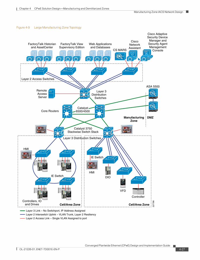
Chapter 4 CPwE Solution Design—Manufacturing and Demilitarized Zones Manufacturing Zone IACS Network Design
Figure 4-9 Large Manufacturing Zone Topology
HMI
Controllers, IOand Drives
IE Swttch
Cell/Area Zone Cell/Area Zone
2277
86
Core Routers
Web Applicationsand Databases
CiscoNetworkAssistant
Cisco Adaptive Security Device
Manager andSecurity AgentManagement
Console
ASA 5500
DMZ
Catalyst 3750Stackwise Switch Stack
ManufacturingZone
Layer 3Distribution
Switches
Catalyst6500/4500
Layer 2 Access Switches
FactoryTalk Historianand AssetCenter
FactoryTalk ViewSupervisory Edition
CS MARS
Controller
VFD
DIO
HMI
IE Swttch
RemoteAccessServer
Layer 2 Interswitch Uplink – VLAN Trunk, Layer 2 Resiliency
Layer 3 Link – No Switchport, IP Address Assigned
Layer 2 Access Link – Single VLAN Assigned to port
Layer 3 Distribution Switches
4-27Converged Plantwide Ethernet (CPwE) Design and Implementation Guide
OL-21226-01, ENET-TD001E-EN-P
Chapter 4 CPwE Solution Design—Manufacturing and Demilitarized Zones Manufacturing Zone IACS Network Design
Manufacturing Zone Topology Summary
Cisco and Rockwell Automation do not have a specific recommendation between the small, medium, and large Manufacturing zone topology options presented. The IACS network requirements, in particular scalability, geographical dispersion, and availability requirements, determine which option to choose.
Note that the large Manufacturing zone topology option represents separating out the Level 3 access, distribution, and core networking functions into distinct equipment. In the small Manufacturing zone topology version, all three Level 3 switch functions are collapsed into the Layer-3 switch stack. It is also possible that only the access or core functions will be separated out, which produces more variations.
RoutingRouting is the process of finding a path to a destination host. Routers or Layer-3 switches forward packets from one network (i.e. sub-network or VLAN) to another based on network layer (IP or Layer 3) information. To do this, routers send each other information about the networks they know about by using various types of protocols—called routing protocols. Routers use this information to build a routing table that consists of the available networks, the cost associated with reaching the available networks, and the path to the next hop router.
For CPwE, routing begins at the Level 3 IACS network, in particular with distribution switches. The distribution switch (e.g., Catalyst 3750) is responsible for routing traffic between Cell/Area IACS networks (inter-VLAN) that it knows about, or into the core, to other routers, or the DMZ. No routing occurs in the Cell/Area IACS network itself. For more information on routing, refer to the following:
Internetwork Design Guidelines: Designing Large-scale IP Networks
Internetworking Technology Handbook: Routing Basics
High-Availability Campus – Layer 3 Routing Protocols
Configuring IOS: IP Overview
For more information on routing basics, refer to the following URL: http://www.cisco.com/en/US/tech/tk1330/tsd_technology_support_technical_reference_chapter09186a008075970b.html
Layer 3 Ports
In Chapter 3, “CPwE Solution Design—Cell/Area Zone,” two key types of Layer 2 ports are identified where the switch forwards incoming packets based on the Layer-2 MAC address:
• End-device or access ports with a specific VLAN assigned to it and other settings
• Uplink or trunk ports connecting switches that carry multiple VLANs in addition to other settings
The Layer-2 managed switch may use other fields in the processing of the packet (e.g., the Layer 3 DSCP field for QoS), but uses the Layer-2 MAC address to determine where to send the packet.
For the Manufacturing zone, a third-type port needs to be introduced, a Layer 3 or routed port. This is a port on which the Layer-3 switch or router will forward incoming traffic based on the Layer-3 IP address, in other words route the packet versus switch the packet. The next section reviews the routing protocols used by the Layer-3 switches or routers to build the routing table. This section simply identifies considerations for port configuration.
4-28Converged Plantwide Ethernet (CPwE) Design and Implementation Guide
OL-21226-01, ENET-TD001E-EN-P

Chapter 4 CPwE Solution Design—Manufacturing and Demilitarized Zones Manufacturing Zone IACS Network Design
Layer 3 ports should be used between switches or routers when no VLANs need to span over that link. Layer 3 links with Layer 3 ports on either end are used:
• Between the distribution and core switches
• Between the plant firewall and core or collapsed core/distribution switches
• Key considerations for a Layer 3 port include the following:
– Use the no switchport command to remove any Layer 2 switchport commands
– Apply an IP address to the port
In addition to the physical ports, any switch/router that needs to route traffic from a VLAN, the VLAN definition will create an switch virtual interface (SVI) that is considered a Layer 3. The default gateway IP address for the subnet is typically assigned to this SVI, either directly or as part of the HSRP configuration for failover between two switches/routers. A Layer 3 link may also be applied to an EtherChannel port-channel, thus making the physical ports assigned to that port channel essentially Layer 3 connections.
Note that the assignment of IP addresses to the Layer 3 ports is considered in the “IP Addressing” section on page 4-38.
For an example of Layer 3 or routed ports configuration, refer to Appendix D, “Configurations.”
Selection of a Routing Protocol
The correct routing protocol is selected based on the characteristics described in the following subsections.
Distance Vector versus Link-State Routing Protocols
Distance vector routing protocols (such as RIPv1, RIPv2, and IGRP) use more network bandwidth than link-state routing protocols, and generate more bandwidth overhead because of large periodic routing updates. Link-state routing protocols (OSPF, IS-IS) do not generate significant routing update overhead but use more CPU cycles and memory resources than distance vector protocols. Enhanced Interior Gateway Routing Protocol (EIGRP) is a hybrid routing protocol that has characteristics of both the distance vector and link-state routing protocols. EIGRP sends partial updates and maintains neighbor state information just as link-state routing protocols do. EIGRP does not send periodic routing updates as other distance vector routing protocols do.
Cisco and Rockwell Automation recommend using EIGRP or OSPF in IACS networks.
Classless versus Classful Routing Protocols
Routing protocols can be classified based on their support for variable-length subnet mask (VLSM) and Classless Inter-Domain Routing (CIDR). Classful routing protocols do not include the subnet mask in their updates, while classless routing protocols do. Because classful routing protocols do not advertise the subnet mask, the IP network subnet mask should be the same throughout the entire network, and should be contiguous for all practical purposes. For example, if you choose to use a classful routing protocol for a network 172.21.2.0 and the chosen mask is 255.255.255.0, all router interfaces using the network 172.21.2.0 should have the same subnet mask. The disadvantage of using classful routing protocols is that you cannot use the benefits of address summarization to reduce the routing table size, and you lose the flexibility of choosing a smaller or larger subnet using VLSM. RIPv1is an example of a classful routing protocol. RIPv2, OSPF, and EIGRP are classless routing protocols. It is very important that the manufacturing zone uses classless routing protocols to take advantage of VLSM and CIDR.
4-29Converged Plantwide Ethernet (CPwE) Design and Implementation Guide
OL-21226-01, ENET-TD001E-EN-P

Chapter 4 CPwE Solution Design—Manufacturing and Demilitarized Zones Manufacturing Zone IACS Network Design
Convergence
Whenever a change in network topology occurs, every router that is part of the network is aware of this change (except if you use summarization). During this period, until convergence happens, all routers use the stale routing table for forwarding the IP packets. The convergence time for a routing protocol is the time required for the network topology to converge such that the router part of the network topology has a consistent view of the network and has the latest updated routing information for all the networks within the topology.
Link-state routing protocols (such as OSPF) and hybrid routing protocol (EIGRP) have a faster convergence as compared to distance vector protocols (such as RIPv1 and RIPv2). OSPF maintains a link database of all the networks in a topology. If a link goes down, the directly connected router sends a link-state advertisement (LSA) to its neighboring routers. This information propagates through the network topology. After receiving the LSA, each router recalculates its routing table to accommodate this topology change. In the case of EIGRP, Reliable Transport Protocol (RTP) is responsible for providing guaranteed delivery of EIGRP packets between neighboring routers. However, not all the EIGRP packets that neighbors exchange must be sent reliably. Some packets, such as hello packets, can be sent unreliably. More importantly, they can be multicast rather than having separate datagrams with essentially the same payload being discretely addressed and sent to individual routers. This helps an EIGRP network converge quickly, even when its links are of varying speeds.
Routing Metric
If a router has a multiple paths to the same destination, there should be some way for a router to pick a best path. This is done using a variable called a metric assigned to routes as a means of ranking the routes from best to worse or from least preferred to the most preferred. Various routing protocols use various metrics, such as the following:
• RIPv1 and RIPv2 use hop count as a metric and therefore are not capable of taking into account the speed of the links connecting two routers. This means that they treat two parallel paths of unequal speeds between two routers as if they were of the same speed, and send the same number of packets over each link instead of sending more over the faster link and fewer or no packets over the slower link. If you have such a scenario in the Manufacturing zone, it is highly recommended to use EIGRP or OSPF because these routing protocols take the speed of the link into consideration when calculating metric for the path to the destination.
• EIGRP uses a composite metric that is based on the combination of lowest bandwidth along the route and the total delay of the route.
• OSPF uses cost of the link as the metric that is calculated as the reference bandwidth (ref-bw) value divided by the bandwidth value, with the ref-bw value equal to 10^8 by default.
Scalability
As the network grows, a routing protocol should be capable of handling the addition of new networks. Link-state routing protocols such as OSPF and hybrid routing protocols such as EIGRP offer greater scalability when used in medium-to-large complex networks. Distance vector routing protocols such as RIPv1 and RIPv2 are not suitable for complex networks because of the length of time they take to converge. Although IS-IS is scalable, IS-IS is not commonly used in Enterprise networks due to the complexity to implement and the fact it does not use IP to communicate routing information. BGP is a protocol commonly found at the Internet edge of enterprise networks, and therefore not a relevant option for plant networks. Factors such as convergence time and support for VLSM and CIDR directly affect the scalability of the routing protocols.
4-30Converged Plantwide Ethernet (CPwE) Design and Implementation Guide
OL-21226-01, ENET-TD001E-EN-P

Chapter 4 CPwE Solution Design—Manufacturing and Demilitarized Zones Manufacturing Zone IACS Network Design
Table 4-4 shows a comparison of routing protocols
In summary, the Manufacturing zone usually has multiple parallel or redundant paths for a destination and requires VLSM for discontinuous major networks. Cisco and Rockwell Automation recommend use of OSPF or EIGRP as the core routing protocol in the Manufacturing zone.
At the time of the writing of this DIG, test results show that EIGRP is better suited to a campus environment than OSPF. The ability of EIGRP to provide route filtering and summarization maps easily to the tiered hierarchical model, while the more rigid requirements of OSPF do not easily integrate to existing implementations and require more complex solutions.
The following are additional considerations when comparing EIGRP and OSPF:
• Within the campus environment, EIGRP provides for faster convergence and greater flexibility.
• EIGRP provides for multiple levels of route summarization and route filtering that map to the multiple tiers of the campus.
• OSPF implements throttles on Link-State Advertisement (LSA) generation and Shortest Path First (SPF) calculations that limit convergence times.
• When routes are summarized and filtered, only the distribution peers in an EIGRP network need to calculate new routes in the event of link or node failure.
Static or Dynamic Routing
The role of a dynamic routing protocol in a network is to automatically detect and adapt to changes to the network topology. The routing protocol decides the best path to reach a particular destination. If precise control of path selection is required, particularly when the path you need is different from the path of the routing protocol, use static routing. Static routing is hard to manage in medium-to-large network topologies, and therefore a dynamic routing protocol is preferred.
Table 4-4 Routing Protocols Comparison
Name TypeProprietary Function Updates Metric VLSM Summarization
RIP Distance vector No Interior 30 sec Hops No Auto
RIPv2 Distance vector No Interior 30 sec Hops Yes Auto
IGRP Distance vector Yes Interior 90 sec Composite No Auto
EIGRP Advanced Distance vector
Yes Interior Trig Composite Yes Both
OSPF Link-state No Interior Trig Cost Yes Manual
IS-IS Link-state No Interior Trig Cost Yes Auto
BGP Path vector No Exterior Incr N/A Yes Auto
4-31Converged Plantwide Ethernet (CPwE) Design and Implementation Guide
OL-21226-01, ENET-TD001E-EN-P

Chapter 4 CPwE Solution Design—Manufacturing and Demilitarized Zones Manufacturing Zone IACS Network Design
Applying the Routing Protocol
The following are the key recommendations to consider as routing is configured for all Manufacturing zone topologies:
• Enable IP directed broadcast. This feature is required to allow IACS software data servers, such as RSLinx Classic with RSWho functionality, to discover the IACS EtherNet/IP devices in the Cell/Area zones. Some Cisco security guidelines suggest disabling this feature, but when strong segmentation with a DMZ is in place, Cisco and Rockwell Automation recommend the feature be enabled within the Manufacturing zone.
• Specify the default gateway on all Cell/Area zone switches and IACS EtherNet/IP devices. This enables the end-devices and switches to send communications outside of the Cell/Area zone.
• Control peering across access layer links (passive interfaces). In most cases, core/distribution switches will not be interconnected via access layer switches, but in the cast that occurs, for example when a VLAN must span multiple distribution switches, steps should be taken to control Layer 3 peering. Unless you control Layer 3 peering in the hierarchical campus model, the distribution nodes establish Layer 3 peer relationships many times using the access nodes that they support, wasting memory and bandwidth.
For topologies where separate core and distribution are in place (medium-to-large):
• Use triangles when configuring core and distribution switch/router ports, See Figure 4-10.
If a topology is built using triangles, with equal-cost paths to all redundant nodes, slower, timer-based convergence can be avoided. Instead of indirect neighbor or route loss detection using hellos and dead timers, you can rely on physical link loss to mark a path as unusable and reroute all traffic to the alternate equal-cost path. Figure 4-10 shows triangle and Figure 4-10 square network topologies. In a square network topology, depending on the location of the failure, the routing protocol may need to converge to identify a new path to the subnet/VLAN, slowing the convergence of the network.
4-32Converged Plantwide Ethernet (CPwE) Design and Implementation Guide
OL-21226-01, ENET-TD001E-EN-P

Chapter 4 CPwE Solution Design—Manufacturing and Demilitarized Zones Manufacturing Zone IACS Network Design
Figure 4-10 Example of Triangle Network Topology
2535
89
IE Switch
Cell/Area Zone Cell/Area Zone
IE Switch
Layer 3 Distribution SwitchesCatalyst 3750 Stackwise Switch Stack
ManufacturingZone
ASA 5500
Core RoutersCatalyst 6500/4500
DMZ
Layer 3 link–no switchport, IP address assigned
Layer 2 interswitch uplink–VLAN Trunk, Layer 2 resiliency
Triangle: Link or Box failure does notrequire routing protocol convergence
4-33Converged Plantwide Ethernet (CPwE) Design and Implementation Guide
OL-21226-01, ENET-TD001E-EN-P

Chapter 4 CPwE Solution Design—Manufacturing and Demilitarized Zones Manufacturing Zone IACS Network Design
Figure 4-11 Example of Square Network Topologies
• Use equal-cost redundant connections from distribution to the core for fastest convergence and to avoid black holes.
• While it is tempting to reduce cost by reducing links between the distribution nodes to the core in a partial mesh design, the complexity and convergence tradeoffs related to this design are ultimately far more expensive.
• Summarization is required to facilitate optimum EIGRP or OSPF convergence. Summarize at the distribution.
It is important to summarize routing information as it leaves the distribution nodes towards the core for both EIGRP and OSPF. When you force summarization at this layer of the network, bounds are implemented on EIGRP queries and OSPF LSA/SPF propagation, which optimizes both routing protocols for campus convergence.
This solution does not cover the option of using multiple “distribution” switches to support a VLAN or set of VLANS. In this case, a Layer 2 connection between the distribution switches is needed. For more information on. The key consideration in this mode include the following:
• Connect distribution nodes to facilitate summarization and maintain Layer 2 VLANs. The devices should have HSRP running to manage the routing. This way, the core has one port/direction for every VLAN/subnet. If summarization is being used, the distribution switches must be linked or routing black holes occur.
For more on configuration of Routing protocols, refer to Configuring IP Routing Protocols at the following URL: http://www.cisco.com/en/US/docs/ios/12_2/ip/configuration/guide/1cfodr.html
2535
90
IE Switch
Cell/Area Zone Cell/Area Zone
IE Switch
Layer 3 Distribution SwitchesCatalyst 3750 Stackwise Switch Stack
ManufacturingZone
ASA 5500
DMZ
Core RoutersCatalyst 6500/4500
Core RoutersCatalyst 6500/4500
Layer 3 link–no switchport, IP address assigned
Layer 2 interswitch uplink–VLAN Trunk, Layer 2 resiliency
Square: Link or Box failure doesrequire routing protocol convergence
4-34Converged Plantwide Ethernet (CPwE) Design and Implementation Guide
OL-21226-01, ENET-TD001E-EN-P

Chapter 4 CPwE Solution Design—Manufacturing and Demilitarized Zones Manufacturing Zone IACS Network Design
Logical SegmentationLogical segmentation is important for the Level 3 IACS network, especially for the CPwE Level 3 workstations and servers. In the Cell/Area zone, it is important for endpoints that communicate Implicit Common Industrial Protocol (CIP) I/O traffic to be in the same VLAN for traffic flow and real-time communications reasons. In the Manufacturing zone, the key consideration for segmentation is security. Security policy may require that certain functions or roles have access to particular applications and services that reside in the Manufacturing zone. In addition, the IACS applications (CPwE Level 3) may need access only to a subset of Cell/Area zones. A well-designed segmentation design greatly improves the ability to apply and maintain a security policy.
The following key functional areas are good candidates for segmentation:
• IACS applications dedicated to particular functions on the plant floor (for example, a brewing control room)
• Remote access server(s)
• Security and network administration applications
As in the Cell/Area zone, a mixture of physical separation and VLANs is used to achieve segmentation.
In this context, there is one particular common practice that Cisco and Rockwell Automation strongly discourages: dual-homing. Dual-homing is the concept of having key Manufacturing zone workstations or servers installed with two network interfaces: one connected to the Manufacturing zone and the other directly to the Enterprise zone. Dual-homing facilitates the sharing of data and services between the two zones. This poses a significant security risk, because these workstations or servers typically are not secured as other devices can be, and are points of entry to the Manufacturing zone for malicious activity to target. The CPwE solution architecture identifies a DMZ with firewall functions to safely and securely share data and services between these zones.
AvailabilityBecause the Cell/Area zone inter-connect functionality exists within the Manufacturing zone, the high availability of the routing infrastructure is critical to the optimal performance of the Manufacturing zone. This section describes design considerations for the following key manufacturing services:
• CPwE Level 3, Layer-2 connectivity
• Core routing and Layer-3 switching
• Network and systems management
• Endpoint security
Layer 2 Connectivity
The CPwE Level 3 workstations and servers are connected to LANs/VLANs. These VLANs also need to be designed with availability considerations. CPwE previously recommended that the redundant topology be applied; therefore, MSTP must be implemented in the Layer 2, Level 3 IACS network to prevent network loops and to recover after the loss of a connection.
4-35Converged Plantwide Ethernet (CPwE) Design and Implementation Guide
OL-21226-01, ENET-TD001E-EN-P

Chapter 4 CPwE Solution Design—Manufacturing and Demilitarized Zones Manufacturing Zone IACS Network Design
Core Routing and Layer-3 Switching Resiliency
Key availability considerations in routing and switching can be divided into hardware and device level considerations and network level considerations.
Network Device Level Resiliency
Device level resiliency refers to techniques that protect against any failure of a device node so that it can continue processing traffic with no or minimum disruption. The techniques relevant to the control network environment are shown in Table 4-5.
Table 4-5 Network Device Level Resiliency Design
Feature Description Supported Platforms
Where to Apply in Industrial Ethernet Network
Redundant route processors (supervisors)
Active and standby supervisors operate in active and standby modes and provide a variety of redundancy mechanisms to handle failure scenarios. Requires redundant devices.
• Catalyst 6500• Catalyst 4500• Catalyst 3750—Virtual with
StackWise
All, especially the Core routing function
StackWise Uses stack interconnect cables to create a virtual switch fabric for stacks of the Catalyst 3750.
• Catalyst 3750• N/A to Other Platforms
All, especially for distribution function
Redundant power supplies
Each system has dual power supplies so that the system operates normally upon failure of a power supply
• Catalyst 6500• Catalyst 4500: Internal• Catalyst 3750: External• Stratix 8000: External• IE 3000: External
All
Redundant fans Each fan tray has multiple fans • Catalyst 6500• Catalyst 4500
All
Line card online insert and removal (OIR)
New line cards can be added or removed without affecting the system or losing the configuration.
• Catalyst 6500• Catalyst 4500
All
Control Plane Policing (CoPP)
Prevents malicious traffic from flooding the CPU to the point that the switch can no longer forward packets and perform functions. Achieved by configuring a QoS filter.
• Catalyst 6500• Catalyst 4500
All
Nonstop Forwarding with Stateful Switchover (NSF with SSO)
Inter-chassis supervisor failover at Layers 2 through 4. Reduces the mean time to recovery (MTTR).
• Catalyst 6500• Catalyst 4500
Whatever Layer 3 routing takes place
In-Service Software Upgrade (ISSU)
Ranges from full image upgrades to granular; selective software maintenance can be performed without service impact across all Cisco IOS-based products.
• Catalyst 6500• Catalyst 4500
4-36Converged Plantwide Ethernet (CPwE) Design and Implementation Guide
OL-21226-01, ENET-TD001E-EN-P

Chapter 4 CPwE Solution Design—Manufacturing and Demilitarized Zones Manufacturing Zone IACS Network Design
Network Level Resiliency
Network level resiliency refers to techniques that can route traffic around a failure point in the network. The techniques relevant to the IACS network environment are shown in Table 4-6.
In addition to these features, Cisco and Rockwell Automation recommend the following be applied at the core and distribution layers to improve resiliency:
• Use GLBP/HSRP millisecond timers.
Automatic software upgrade for Catalyst 3750 StackWise
The Master 3750 transfers the same version of code to the remaining switches in the stack. The upgrade includes
• Transfer the global configuration• Apply default configuration• Apply preconfigured configuration
Catalyst 3750 All
Generic Online Diagnostics (GOLD)
Online diagnostics to help ensure that a system that is booting up and a live system are healthy.
Catalyst 6500, 4500 and 3750: subset of GOLD
All
Configuration rollback
Capability to replace the current running configuration with any saved Cisco IOS configuration file
Catalyst 6500
Table 4-5 Network Device Level Resiliency Design (continued)
Feature Description Supported Platforms
Where to Apply in Industrial Ethernet Network
Table 4-6 Network Level Resiliency Design
Feature Description Supported Platforms
Where to Apply in Industrial Ethernet Network
Link redundancy Sends packets to their destinations over a backup link of a network device when its primary link fails because of link breakage, or failure of an interface or line card. Determined by the Layer 2 resiliency or a Layer 3 routing protocol.
All routers and switches All
Hot Standby Router Protocol (HSRP)
Cisco proprietary redundancy protocol for establishing a fault-tolerant default gateway.
• Catalyst 6500• Catalyst 4500• Catalyst 3750—Virtual
with StackWise
Between routers/switches performing similar functions (e.g. redundant core switches). It is not needed on a 3750-stack to manage the switches in the stack.
Incremental SPF Optimizations
Optimization of the OSPF algorithm to reduce computational load.
• Catalyst 6500 - Internal• Catalyst 4500—Internal• Catalyst 3750—External
All
IP dampening Mechanism to suppress affects of excessive state changes (flapping).
• Catalyst 6500• Catalyst 4500
All
4-37Converged Plantwide Ethernet (CPwE) Design and Implementation Guide
OL-21226-01, ENET-TD001E-EN-P
Chapter 4 CPwE Solution Design—Manufacturing and Demilitarized Zones Manufacturing Zone IACS Network Design
Convergence around a link or node failure in the Layer-2/Layer-3 distribution boundary model depends on default gateway redundancy and failover. Millisecond timers can reliably be implemented to achieve sub-second (800 ms) convergence based on HSRP/GLBP failover.
• Tune GLBP/HSRP preempt delay to avoid black holes.
Ensure that the distribution node has connectivity to the core before it preempts its HSRP/GLBP standby peer so that traffic is not dropped while connectivity to the core is established.
IP AddressingIP addressing is an important concept for IACS networking. For all practical purposes, every IACS network device (server, endpoint, infrastructure device) on the industrial Ethernet network is assigned an IP address, and is thereby addressable within the Manufacturing zone.
This section addresses the following:
• Provides a brief background on IP addressing and some helpful links for more information
• Reviews best practices for IP address management in plant manufacturing environments
• Reviews best practices for IP address allocation in the Manufacturing zone
IP Addressing Background
As with most concepts described here, there are multiple versions of standards in use. That is also true for IP addressing. The two key IP addressing standards relevant in standard networking are IPv4 and IPv6. IPv4 defines an IP address as a 32-bit number and is currently the most prevalent IP addressing standard in use, not just in manufacturing but in general. IPv6 defines an IP address as a 128-bit number and is currently only adopted in a small percentage of devices and relatively unknown in IACS networks. Most IACS network devices available today do not support IPv6 addressing along with the relevant IACS protocols and standards (ODVA's CIP, EtherNet/IP included). Therefore, this DIG assumes IPv4 is the IP addressing standard in effect.
Refer to the following key documents about IP addressing:
• IP Addressing and Subnetting for New Users
• Internetworking Technology Handbook: IP
• Configuring IP Addressing
IP Address Management
IP address management is the process of allocating, recycling, and documenting IP addresses and subnets in a network. IP addressing standards define subnet size, subnet assignment, network device assignments, and dynamic address assignments within a subnet range. Recommended IP address management standards reduce the opportunity for overlapping or duplicate subnets, non-summarization in the network, duplicate IP address device assignments, wasted IP address space, and unnecessary complexity.
Developing an appropriate IP addressing schema for an IACS network with considerations for future expansion is critical. Changing IP addressing schemas are difficult, time consuming and involve IACS network downtime.
4-38Converged Plantwide Ethernet (CPwE) Design and Implementation Guide
OL-21226-01, ENET-TD001E-EN-P

Chapter 4 CPwE Solution Design—Manufacturing and Demilitarized Zones Manufacturing Zone IACS Network Design
Address Space Planning
When planning address space, administrators must be able to forecast the IP address capacity requirements and future growth in every accessible subnet on the network. This is based on many factors such as number of end-devices, number of users working on the plant floor, number of IP addresses required for each application or each end-device, and so on. Even with plentiful availability of private address space, the cost associated with supporting and managing the IP addresses can be huge. With these constraints, it is highly recommended that administrators plan and accurately allocate the addressing space with future growth into consideration.
Hierarchical Addressing
Hierarchical addressing leads to efficient allocation of IP addresses. An optimized address plan is a result of good hierarchical addressing. A hierarchical address plan allows you to take advantage of all possible addresses because you can easily group them contiguously. With random address assignment, there is a high possibility of wasting groups of addresses because of addressing conflicts.
Another benefit of hierarchical addressing is a reduced number of routing table entries. The routing table should be kept as small as possible by using route summarization.
Summarization (also known as supernetting) allows aggregation of smaller subnets that reside on that network into a single route in the routing table. Route summarization is a way of having a single route represent multiple smaller routes, which can be very well accomplished when hierarchical addressing is used. By summarizing routes, you can keep the routing table entries small, which offers the following benefits:
• Efficient routing
• Reduced router memory requirements
• Reduced number of CPU cycles when recalculating a routing table or going through routing table entries to find a match
• Reduced bandwidth required because of fewer small routing updates
• Easier troubleshooting
• Fast convergence
• Increased network stability because detailed routes are hidden, and therefore impact to the network when the detailed routes fail is reduced
If address allocation is not done hierarchically, there is a high chance of duplicate IP addresses being assigned to end-devices. In addition, networks can be unreachable if route summarization is configured.
Hierarchical addressing helps in allocating address space optimally and is the key to maximizing address use in a routing-efficient manner.
Note Overlapping IP addresses should be avoided in the Manufacturing Cell/Area zone. If two devices have identical IP addresses, the ARP cache may contain the MAC (node) address of another device, and routing (forwarding) of IP packets to the correct destination may fail. CPwE recommends that IACS network devices should be hard-coded with a properly unique static IP address.
4-39Converged Plantwide Ethernet (CPwE) Design and Implementation Guide
OL-21226-01, ENET-TD001E-EN-P

Chapter 4 CPwE Solution Design—Manufacturing and Demilitarized Zones Manufacturing Zone IACS Network Design
Note CPwE recommends that the traffic associated with any multicast address (224.0.0.0 through 239.255.255.255) used in the Manufacturing zone should not be permitted in the Enterprise zone; EtherNet/IP devices in the Manufacturing zone use an algorithm to choose a multicast address for their Implicit CIP I/O traffic. Therefore, to avoid conflict with multicast addresses in the Enterprise zone, use the DMZ to segment multicast traffic in the Manufacturing zone from multicast traffic in the Enterprise zone.
Centralized IP Addressing Inventory
Address space planning and assignment can be best achieved using a centralized approach and maintaining a central IP inventory repository or database. The centralized approach provides a complete view of the entire IP address allocation of various sites within an organization. This helps in reducing IP address allocation errors and also reduces duplicate IP address assignment to end-devices. The IT department is usually responsible for maintaining a centralized IP addressing schema and inventory for an enterprise.
Multicast IP Addresses
As stated earlier, IACS applications and in particular EtherNet/IP implementations generate multicast traffic. The IP standards have set aside a range of IP addresses for the exclusive use of multicast traffic (see the URL below). It is important to consider the multicast addresses used in the IACS network devices and to avoid address overlap with other applications that may use multicast and not allow the IACS multicast traffic to mix with enterprise traffic to ensure application consistency.
Internet Protocol IP Multicast Technology:
http://www.cisco.com/en/US/tech/tk828/tech_brief09186a00800a4415.html
For more information on the range of IP multicast addresses used with EtherNet/IP applications see (ODVA).
Private and Public IP Addresses
The IPv4 (RFC 1918 and 4193) standard also allots a range of IP address for private use. These addresses can be used within a private network but cannot be used on the Internet. Any company or individual can use these addresses within their internal networks.
The IACS network traffic is confined to the Manufacturing zone. Because of this, either private or public IP addresses can be used for the Manufacturing zone. Routable IP addresses are an extremely limited resource. Not all organizations have been assigned routable IP addresses. If an organization has public addresses, they typically have a relatively small number of addresses assigned to them. Using private IP addresses in the Manufacturing zone frees up the public addresses for other purposes. It is important that a unique summerizable block of IP addresses is assigned to the Manufacturing zone.
In the end, the use of private or public IP addresses is going to depend highly on the enterprise and the overall IP approach.
For more information and pros/cons on private IP addresses, see Address Allocation for Private Internets.
4-40Converged Plantwide Ethernet (CPwE) Design and Implementation Guide
OL-21226-01, ENET-TD001E-EN-P

Chapter 4 CPwE Solution Design—Manufacturing and Demilitarized Zones Manufacturing Zone IACS Network Design
Subnetworks
IP networks are divided into smaller network called subnets. Each subnet represents a group of hosts on the network. Hosts on the same subnet communicate directly with each other over the Layer 2 network. Hosts on different subnets communicate with each other via their default gateways. Subnets divide the IP network into smaller, more manageable networks. In the CPwE architecture, each VLAN in the Manufacturing zone has a unique subnet assigned to it.
Network Address Translation (NAT)
NAT is another mechanism for reducing the need for globally unique IP addresses. NAT allows an organization with addresses that are not globally unique to connect to the Internet by translating those addresses into globally routable address space. NAT operates on a router connecting two networks together; one of these networks (designated as inside) is addressed with either private or duplicate public addresses that need to be converted into unique public addresses before packets are forwarded onto the other network (designated as outside). Devices on the inside assigned a unique IP address via NAT are also addressable from the outside.
Another reason NAT is attractive to IACS networking, besides the need to conserve IP addresses, is the opportunity to reuse IP address schemas for different parts of the IACS network. By reusing IP address schemas, manufacturers and their partners hope to reduce the test and implementation of cookie-cutter systems or lines on the plant floor by repeating the IP address schema for parts of the IACS network.
The disadvantages with NAT include the following:
• Additional overhead to develop and maintain NAT translation schemas
• NAT likely will leave a number of devices as un-addressable from outside of the NAT’d region, any that do not receive a NAT address
• NAT may impact applications that use embedded IP addresses in the data packet.
• Data servers for IACS application software may not properly support NAT
Cisco and Rockwell Automation do not recommend the use of NAT services in the Manufacturing zone.
• Cisco IOS NAT Overview: http://www.cisco.com/en/US/tech/tk648/tk361/technologies_q_and_a_item09186a00800e523b.shtml
• NAT Frequently Asked Questions: http://www.cisco.com/en/US/tech/tk648/tk361/technologies_q_and_a_item09186a00800e523b.shtml
• How NAT Works: http://www.cisco.com/en/US/tech/tk648/tk361/technologies_tech_note09186a0080094831.shtml
Dynamic Name Services
Domain Name System (DNS) is used for translating names of network hosts into addresses. DNS is used as an abstraction layer between IP addresses, applications and services. DNS allows a host to be identified by its name instead of its IP address. If the IP address of the host is changed, DNS is updated to reflect the new address. The client application continues to communicate with the name and does not need to know that the address has changed.
4-41Converged Plantwide Ethernet (CPwE) Design and Implementation Guide
OL-21226-01, ENET-TD001E-EN-P
Chapter 4 CPwE Solution Design—Manufacturing and Demilitarized Zones Manufacturing Zone IACS Network Design
Cisco and Rockwell Automation recommend referencing Cell/Area IACS network devices by their static IP address as opposed to their DNS name for simplicity and to avoid potential latency delays if the DNS server has issues. DNS resolution delays may not be acceptable depending on the IACS application. DNS may be used effectively for certain Level 3 IACS applications and systems. In this case, a DNS service must be established to perform the name translation.
Note that DNS is a network service commonly used throughout most enterprise networks. Due to the strong segmentation recommended by this CPwE solution, the DNS names found in the Enterprise zone do not need to be available in the Manufacturing zone; therefore replication of DNS services between Enterprise and Manufacturing zones may not be required.
Other IP Address Considerations
As IP address schemas for the IACS network are developed, here are some other considerations:
• If a Management VLAN is implemented, a unique subnet and VLAN should be applied to the switching infrastructure.
• Loopback Interfaces. Loopback addresses for system logging should be established for effective of system messages. If you have available IP address space or can allocate a range of IP subnets for the loopback interface, it will be easier for you to manage your network, utilizing some of the configuration techniques. A loopback interface requires its own IP subnet. But you can use a host mask (255.255.255.255 or /32) for this interface because no other device uses that subnet.
• If you are short on IP addresses, the loopback interface is probably not a viable option. In that case, consider “key” physical interfaces, such as backbone-oriented interfaces, for use as source IP addresses for SNMP traps or syslog messages because those interfaces should be up most of the time.
– Source the traps from the Loopback0 interface using the snmp-server trap-source Loopback0 configuration command. By doing this, you can control where traps are sourced from versus having multiple IP address sourcing the traps. By default, all traps are sourced from the outgoing physical interface's IP address. It is easier to track one IP address or hostname than multiple IP addresses or hostnames from a common host (Cisco device).
IP Address Allocation
This section covers the mechanisms used to deploy IP addresses to end-devices once an IP addressing schema has been established. The section looks at both static and dynamic methods and summarizes the recommendations.
Static IP Addressing
In the Manufacturing zone, the Level 3 workstations and servers are static. Additionally, it is recommended to statically configure Cell/Area IACS network devices.
The Level 3 servers send detailed scheduling, execution, and operator IACS data to controllers in the Manufacturing zone, and collect data from the controllers for historical data and audit purposes. Cisco and Rockwell Automation recommend manually assigning IP addresses to all the IACS networking devices including servers and Cisco networking equipment in the Manufacturing zone. For more information on IP addressing, see IP Addressing and Subnetting for New Users at the following URL: http://www.cisco.com/en/US/customer/tech/tk365/technologies_tech_note09186a00800a67f5.shtml
4-42Converged Plantwide Ethernet (CPwE) Design and Implementation Guide
OL-21226-01, ENET-TD001E-EN-P

Chapter 4 CPwE Solution Design—Manufacturing and Demilitarized Zones Manufacturing Zone IACS Network Design
Using Dynamic Host Configuration Protocol and DHCP Option 82
Dynamic Host Configuration Protocol (DHCP) is used in LAN environments to dynamically assign host IP addresses from a centralized server, which reduces the overhead of administrating IP addresses. DHCP also helps conserve limited IP address space because IP addresses no longer need to be permanently assigned to client devices; only those client devices that are connected to the network require an IP addresses. The DHCP relay agent information feature (option 82) enables the DHCP relay agent (Catalyst switch) to include information about itself and the attached client when forwarding DHCP requests from a DHCP client to a DHCP server. This extends the standard DHCP process by tagging the request with the information regarding the location of the requestor. See Figure 4-12.
Figure 4-12 DHCP Option 82 Operation
The following are key elements required to support the DHCP option 82 feature:
• Clients supporting DHCP
• Relay agents supporting option 82
• DHCP server supporting option 82
The relay agent information option is inserted by the DHCP relay agent when forwarding the client-initiated DHCP request packets to a DHCP server. The servers recognizing the relay agent information option may use the information to assign IP addresses and to implement policies such as restricting the number of IP addresses that can be assigned to a single circuit ID. The circuit ID in relay agent option 82 contains information identifying the port location on which the request is arriving.
For details on DHCP features, see the following URL: http://www.cisco.com/en/US/products/ps7077/products_configuration_guide_chapter09186a008077a28b.html#wp1070843
The DHCP option 82 feature is supported only when DHCP snooping is globally-enabled and on the VLANs to which subscriber devices using this feature are assigned. DHCP and the DHCP option 82 feature have not been validated in the lab for CPwE version 2.0
At this time, Cisco and Rockwell Automation do not recommend dynamic IP address allocation in the CPwE architecture. Table 4-7 provides a summary of IP address allocation mechanisms used for this solution.
DHCP Client
DHCP Client
DHCP Server
Clients generates aDHCP request
Relay agent fills in Option 82 (Remote ID and Circuit ID)
along with gateway IP address and unicast to DHCP server
DHCP server Option 82 capable, use the
appended information
Based on appendedinformation, returns with proper
IP address and policies
Removes Option 82, implement policy and
IP address assignment
1
2 3
5 4
2210
76
4-43Converged Plantwide Ethernet (CPwE) Design and Implementation Guide
OL-21226-01, ENET-TD001E-EN-P

Chapter 4 CPwE Solution Design—Manufacturing and Demilitarized Zones Manufacturing Zone IACS Network Design
IP Address Summary
There are several ways to allocate IP addresses. Table 4-7 lists a number of variations and their advantages and disadvantages. Cisco and Rockwell Automation recommend that network developers use either a static IP addressing schema or DHCP persistence for the Manufacturing zone, especially for allocating IP addresses to IACS devices in the Cell/Area zone. DHCP persistence provides a dynamic IP allocation mechanism on a IES per-port basis. For more information on DHCP persistence, refer to Chapter 10, “DHCP Persistence in the Cell/Area Zone.”
Table 4-7 Summary of IP Address Allocation mechanisms
Option Description Advantages Disadvantages
Static IACS network device hard coded with an IP Address through mechanical means such as a rotary switch
Simple to commission and replace
In large environments, can be burdensome to maintain
Limited ranged of IP addresses and subnet
Not all devices support
Static via BOOTP Configuration
Server, through manual intervention, assigns IACS network devices IP addresses
Precursor to DHCP
Supported by every device Requires technician to configure IP address/MAC address when a device is replaced
Adds complexity and point of failure
DHCP Server automatically assigns IP addresses from a pool (NOT RECOMMENDED for Cell/Area zone IACS devices)
Efficient use of IP address range
Can reduce administration work load
More complex to implement and adds a point of failure
Devices get different IP addresses when they reboot
DHCP Option 82 Server assigns consistent IP addresses from a pool (NOT RECOMMENDED)
Efficient use of IP Address range
Can reduce administration work load
More complex to implement and adds a point of failure
Mixed environments may not work
DHCP Persistence Automatically assign IP address per physical switch port
Efficient use of IP Address range
Eases commissioning and maintenance in large environments
Cisco/RA only
Requires some maintenance and upkeep, on a per switch basis
4-44Converged Plantwide Ethernet (CPwE) Design and Implementation Guide
OL-21226-01, ENET-TD001E-EN-P

Chapter 4 CPwE Solution Design—Manufacturing and Demilitarized Zones Manufacturing Zone IACS Network Design
Security Design
The security design for the Manufacturing zone network infrastructure builds upon the IACS network infrastructure security recommendations made for the Cell/Area zone, but includes concepts to protect the network features specific to the Manufacturing zone, especially routing and protecting the applications and servers specific to the Manufacturing zone (e.g., the FactoryTalk Integrated Production and Performance Suite). The key concepts applied in the Cell/Area zone that also apply to the Manufacturing zone include:
• Network Infrastructure Device Access, covering port security, password maintenance, administrative access
• Resiliency and survivability, covering redundancy and disabling un-necessary services
• Network Telemetry, covering network system message logging, SNMP, SSH, and network information to monitor
• Other zone security best practices, covering restricting broadcast domains, VLANs and protecting a variety of network protocols
This section will not go into detail on the design considerations as they are sufficiently covered in Chapter 3, “CPwE Solution Design—Cell/Area Zone,” Section Security as well as Cisco's SAFE solution. The topics covered in this section include:
• Routing Infrastructure protection
Note that more advanced protection mechanisms are also possible, but probably beyond the majority of IACS networks. These may be considered by advanced IACS network teams, larger installations or highly sensitive installations. Some of the advanced techniques include the following:
– Establishing infrastructure ACLs (iACLs) to explicitly permit authorized control and management traffic bound to the IACS network infrastructure equipment
• Control Plane Policing and Protection to protect the network traffic and data used by the network infrastructure.
• Network Policy Enforcement that ensures traffic entering a network conforms to the network policy, including the IP address range and traffic types
All of these concepts and techniques are described in more detail in Cisco's SAFE and Network Security Baseline solutions at the following URL: http://www.cisco.com/en/US/docs/solutions/Enterprise/Security/SAFE_RG/SAFE_rg.html
Routing Infrastructure Protection
Routing is one of the key features for the Manufacturing zone IACS network. Therefore, steps to secure the routing protocol are critical to maintaining overall IACS security and availability. The routing protocol may be compromised via injection of improper routing data, denial-of-service or used to target attacks on other devices in the network. The key measures Cisco and Rockwell Automation recommend to protect the routing function include:
• Restrict routing protocol membership- Limit routing sessions to trusted peers, validate origin, and integrity of routing updates.
• Log status changes adjacency or neighbor sessions.
4-45Converged Plantwide Ethernet (CPwE) Design and Implementation Guide
OL-21226-01, ENET-TD001E-EN-P

Chapter 4 CPwE Solution Design—Manufacturing and Demilitarized Zones Server Farm
Restrict Routing Protocol Membership
The key considerations for an IACS network in this technique are to enable routing neighbor authentication and to statically configure a list of trusted neighbors. For most IACS networks, the routers are not going to be very dynamic therefore the effort involved will be minimal and ensures that dynamic mechanisms do not identify invalid routers. This should keep the routing function in a Manufacturing zone segmented by plant firewalls and a DMZ well protected. There are other considerations listed in the referred to documentation, but they are either for different types of networks or are already covered in other security recommendations.
For details on these techniques and implementation guidance, see Cisco's SAFE and Network Security Baseline solutions. For more on the authentication techniques for each protocol, see
• Configuring EIGRP Authentication—http://www.cisco.com/en/US/tech/tk365/technologies_configuration_example09186a00807f5a63.shtml
• Configuring IS-IS Authentication— http://www.cisco.com/en/US/tech/tk365/technologies_configuration_example09186a0080093f36.shtml
• Configuring OSPF Authentication— http://www.cisco.com/en/US/tech/tk365/technologies_configuration_example09186a0080093f36.shtml
Log Status Changes
Logging of status changes that impact the routing protocols is important to maintaining security. If frequent or unexpected changes occur, they may indicate an ongoing attack or vulnerability. In most routing protocols, status change message logging is enabled by default. When enabled, every time a router session goes down, up, or experiences a reset, the router generates a log message. If syslog is enabled as recommended by this solution, the message is forwarded to the syslog server; otherwise is kept in the router's internal buffer.
For details on these techniques and implementation guidance, see Cisco's SAFE and Network Security Baseline solutions at the following URL:
http://www.cisco.com/en/US/docs/solutions/Enterprise/Security/SAFE_RG/SAFE_rg
Server Farm
Types of ServersThe servers used in the Manufacturing zone can be classified into three categories.
• Servers that provide common network-based services such as the following:
– DNS—Primarily used to resolve hostnames to IP addresses.
– DHCP—Used by end-devices to obtain IP addresses and other parameters such as the default gateway, subnet mask, and IP addresses of DNS servers from a DHCP server. The DHCP server makes sure that all IP addresses are unique; that is, no IP address is assigned to a second end-device if a device already has that IP address.
– Directory services—Set of applications that organizes and stores date about end users and network resources.
4-46Converged Plantwide Ethernet (CPwE) Design and Implementation Guide
OL-21226-01, ENET-TD001E-EN-P
Chapter 4 CPwE Solution Design—Manufacturing and Demilitarized Zones Server Farm
– Network Time Protocol (NTP)—Synchronizes the time on a network of machines. NTP runs over UDP, using port 123 as both the source and destination. An NTP network usually gets its time from an authoritative time source, such as a radio clock or an atomic clock attached to a time server. NTP then distributes this time across the network. An NTP client makes a transaction with its server over its polling interval (64–1024 seconds,) which dynamically changes over time depending on the network conditions between the NTP server and the client. No more than one NTP transaction per minute is needed to synchronize two machines.
– Precision Time Protocol (PTP) is not being addressed in this version of CPwE.
For more information, see Network Time Protocol: Best Practices White Paper at the following URL:
http://www.cisco.com/en/US/customer/tech/tk869/tk769/technologies_white_paper09186a0080117070.shtml
• Servers that provide security and network management services such as the following:
– Cisco Security Monitoring, Analysis, and Response System (MARS)—Provides security monitoring for network security devices and host applications made by Cisco and other providers.
– Greatly reduces false positives by providing an end-to-end view of the network
– Defines the most effective mitigation responses by understanding the configuration and topology of your environment
– Promotes awareness of environmental anomalies with network behavior analysis using NetFlow
– Makes precise recommendations for threat removal, including the ability to visualize the attack path and identify the source of the threat with detailed topological graphs that simplify security response at Layer 2 and above
For more information on CS-MARS, see the CS-MARS introduction at the following URL:
http://www.cisco.com/en/US/customer/products/ps6241/tsd_products_support_series_home.html
– Cisco Network Assistant (CNA)—PC-based network management application optimized for wired and wireless LANs for growing businesses that have 40 or fewer switches and routers. Using Cisco Smartports technology, Cisco Network Assistant simplifies configuration, management, troubleshooting, and ongoing optimization of Cisco networks. The application provides a centralized network view through a user-friendly GUI. The program allows network administrators to easily apply common services, generate inventory reports, synchronize passwords, and employ features across Cisco switches, routers, and access points.
For more information, see the Cisco Network Assistant general information at the following URL: http://www.cisco.com/en/US/customer/products/ps5931/tsd_products_support_series_home.html
• CiscoWorks LAN Management Solution (LMS)—CiscoWorks LMS is a suite of powerful management tools that simplify the configuration, administration, monitoring, and troubleshooting of Cisco networks. It integrates these capabilities into a best-in-class solution for the following:
– Improving the accuracy and efficiency of your operations staff
4-47Converged Plantwide Ethernet (CPwE) Design and Implementation Guide
OL-21226-01, ENET-TD001E-EN-P

Chapter 4 CPwE Solution Design—Manufacturing and Demilitarized Zones Server Farm
– Increasing the overall availability of your network through proactive planning
– Maximizing network security
For more information, see CiscoWorks LMS at the following URL:
http://www.cisco.com/en/US/customer/products/sw/cscowork/ps2425/tsd_products_support_series_home.html
• Servers that provide manufacturing services such as the following:
– Data servers such as RSLinx Classic and Enterprise
– FactoryTalk Servers such as Historian, View, AssetCentre, and Batch
– FactoryTalk Services platform such as Directory, Security, Audit, Diagnostics, Live Data, Activation, and Alarms & Events
– Engineering workstation such as RSLogix 5000/500/5
The recommendation is put the above three categories into three separate VLANs. If necessary, the manufacturing application servers can be further segregated based on their functionality.
Security Protection for Servers
The servers that provide network services, network management, or Level 3 Site Manufacturing Operations and Control should be provided with the following security protection:
• Reusable passwords—Users likely authenticate to their systems with username and passwords.
• Session security—Application crypto-any communication between a client to a server considered sensitive (based on the security policy) should be cryptographically protected with session-application crypto.
• OS/application hardening—Harden the OS and any application. Do not simply deploy every patch as it is released. Use some mechanism to do testing on updates before applying to IACS systems. Also, make sure to follow hardening guides for popular applications, such as Microsoft Internet Information Server (IIS) and Apache web server, used on the servers.
• Partitioning disk space—In the event of a problem, limit the ability of one rogue process to consume the entire disk space of the server. In Unix, for example, it is good practice to set aside separate partitions for the following components: /, /var, /home, /usr, and /tmp.
• Turning off unneeded services—If the host is a standard desktop, it probably does not need to run any services for other users such as FTP. If it is a server, the running services should be limited to those that are required to perform the job of the server. For example, this means running HTTP but not Telnet on a web server.
• Deploying the Cisco Security Agent (CSA)—The CSA protects critical servers by being a host-based IDS to help mitigate local attacks. See Endpoint Protection with Cisco Security Agent, page 5-33.
Endpoint Protection with Cisco Security Agent
No security strategy can be effective if the servers and desktop computers (endpoints) are not protected. Endpoint attacks typically run in stages: probe, penetrate, persist, propagate, and paralyze. Most endpoint security technologies provide early stage protection (and then only when a signature is known).
4-48Converged Plantwide Ethernet (CPwE) Design and Implementation Guide
OL-21226-01, ENET-TD001E-EN-P

Chapter 4 CPwE Solution Design—Manufacturing and Demilitarized Zones Server Farm
The Cisco Security Agent (CSA) proactively defends against damage to a host throughout all stages of an intrusion, and is specifically designed to protect against new attacks where there is no known signature. The CSA goes beyond conventional endpoint security solutions by identifying and preventing malicious behavior before it can occur, thereby removing potential known and unknown security risks that threaten enterprise networks and applications.
When an application attempts an operation, the agent checks the operation against the security policy of the application. The agent makes a real-time “allow” or “deny” decision on its continuation and determines whether that request should be logged. Because protection is based on blocking malicious behavior, the default policies stop both known and unknown attacks without needing updates. Correlation is performed both at the agent and the management center console. Correlation at the agent results in dramatically increased accuracy, identifying actual attacks or misuse without blocking legitimate activity. Correlation at the management center identifies global attacks such as network worms or distributed scans.
Server Farm Access Layer
Layer 2 Access Considerations
The Layer-2 access switch provides physical connectivity to the server farm. The applications residing on these servers for the Manufacturing zone are considered to be critical for the operation of the IACS. It is recommended that these servers be dual-homed to the Layer 2 access switches through NIC teaming.
The Layer-2 access switch is connected to the aggregation layer through an IEEE 802.1Q trunk. The first point of Layer 3 processing is at the distribution switch. There is no Layer-3 routing done in the access switch.
Spanning VLANs across Access Layer switches
For applications that require spanning VLANs across Layer 2 access switches, and Spanning Tree protocol (STP) is used as the resiliency protocol, take the following steps to make the best of this suboptimal situation:
• Use RPVST+ as the version of STP. When Spanning Tree convergence is required, RPVST+ is superior to PVST+ or STP.
• Provide a Layer 2 link between the two distribution switches to avoid unexpected traffic paths and multiple convergence events.
If you choose to load balance VLANs across uplinks, be sure to place the HSRP primary and the RPVST+ primary on the same distribution layer switch. The HSRP and RPVST+ root should be collocated on the same distribution switches to avoid using the inter-distribution link for transit.
For more information, see Campus Network Multilayer Architecture and Design Guidelines at the following URL:
http://www.cisco.com/en/US/solutions/ns340/ns414/ns742/ns815/landing_cOverall_design.html
Figure 4-13 shows an example of a Layer-2 access topology.
4-49Converged Plantwide Ethernet (CPwE) Design and Implementation Guide
OL-21226-01, ENET-TD001E-EN-P
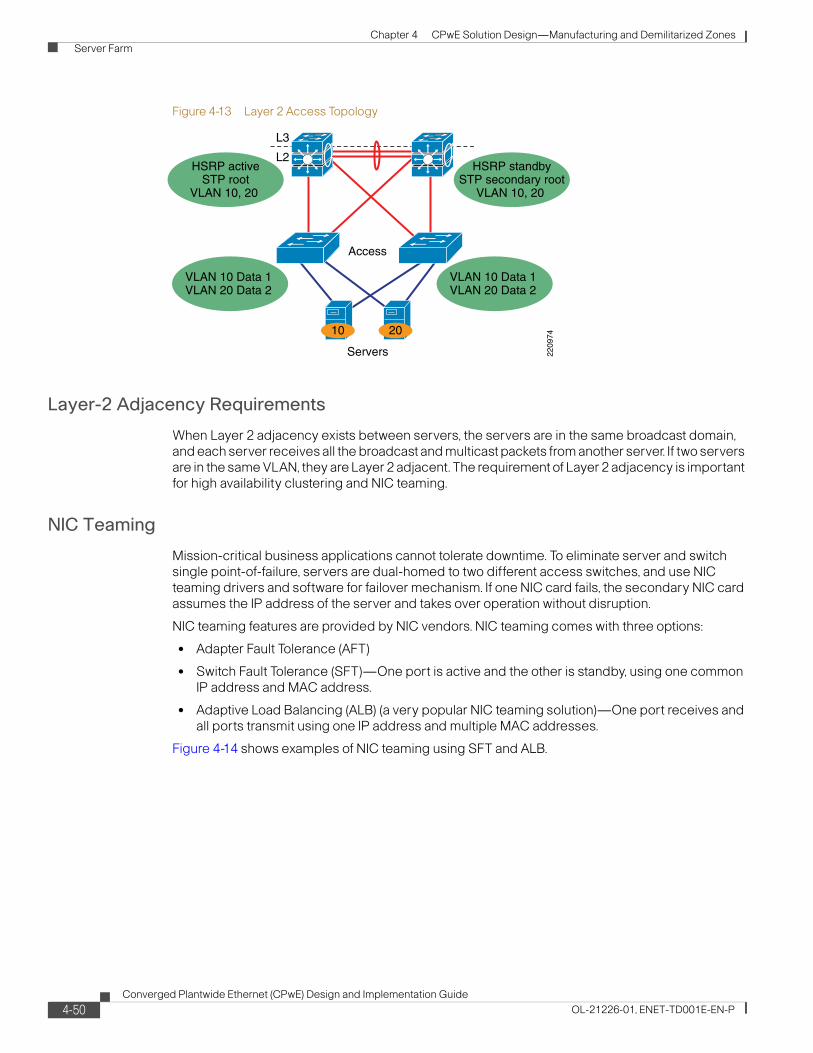
Chapter 4 CPwE Solution Design—Manufacturing and Demilitarized Zones Server Farm
Figure 4-13 Layer 2 Access Topology
Layer-2 Adjacency Requirements
When Layer 2 adjacency exists between servers, the servers are in the same broadcast domain, and each server receives all the broadcast and multicast packets from another server. If two servers are in the same VLAN, they are Layer 2 adjacent. The requirement of Layer 2 adjacency is important for high availability clustering and NIC teaming.
NIC Teaming
Mission-critical business applications cannot tolerate downtime. To eliminate server and switch single point-of-failure, servers are dual-homed to two different access switches, and use NIC teaming drivers and software for failover mechanism. If one NIC card fails, the secondary NIC card assumes the IP address of the server and takes over operation without disruption.
NIC teaming features are provided by NIC vendors. NIC teaming comes with three options:
• Adapter Fault Tolerance (AFT)
• Switch Fault Tolerance (SFT)—One port is active and the other is standby, using one common IP address and MAC address.
• Adaptive Load Balancing (ALB) (a very popular NIC teaming solution)—One port receives and all ports transmit using one IP address and multiple MAC addresses.
Figure 4-14 shows examples of NIC teaming using SFT and ALB.
Access
L3
L2
Servers
VLAN 10 Data 1VLAN 20 Data 2
VLAN 10 Data 1VLAN 20 Data 2
HSRP standbySTP secondary root
VLAN 10, 20
HSRP activeSTP root
VLAN 10, 20
2010
2209
74
4-50Converged Plantwide Ethernet (CPwE) Design and Implementation Guide
OL-21226-01, ENET-TD001E-EN-P
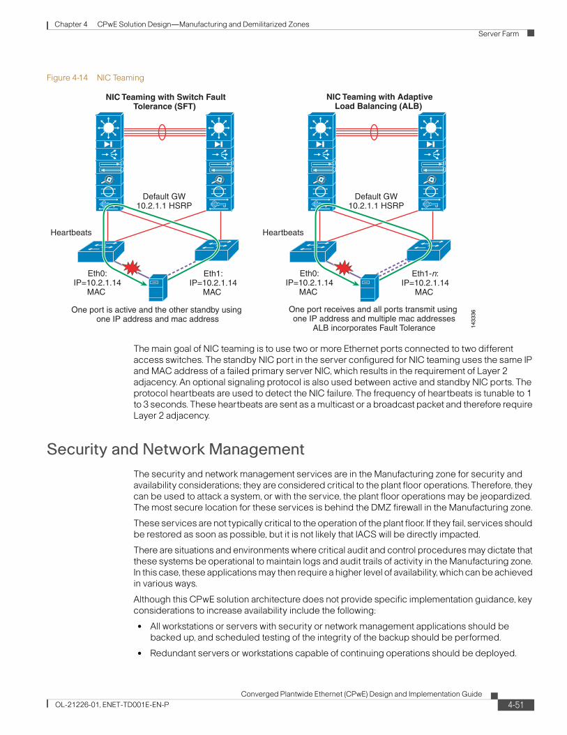
Chapter 4 CPwE Solution Design—Manufacturing and Demilitarized Zones Server Farm
Figure 4-14 NIC Teaming
The main goal of NIC teaming is to use two or more Ethernet ports connected to two different access switches. The standby NIC port in the server configured for NIC teaming uses the same IP and MAC address of a failed primary server NIC, which results in the requirement of Layer 2 adjacency. An optional signaling protocol is also used between active and standby NIC ports. The protocol heartbeats are used to detect the NIC failure. The frequency of heartbeats is tunable to 1 to 3 seconds. These heartbeats are sent as a multicast or a broadcast packet and therefore require Layer 2 adjacency.
Security and Network ManagementThe security and network management services are in the Manufacturing zone for security and availability considerations; they are considered critical to the plant floor operations. Therefore, they can be used to attack a system, or with the service, the plant floor operations may be jeopardized. The most secure location for these services is behind the DMZ firewall in the Manufacturing zone.
These services are not typically critical to the operation of the plant floor. If they fail, services should be restored as soon as possible, but it is not likely that IACS will be directly impacted.
There are situations and environments where critical audit and control procedures may dictate that these systems be operational to maintain logs and audit trails of activity in the Manufacturing zone. In this case, these applications may then require a higher level of availability, which can be achieved in various ways.
Although this CPwE solution architecture does not provide specific implementation guidance, key considerations to increase availability include the following:
• All workstations or servers with security or network management applications should be backed up, and scheduled testing of the integrity of the backup should be performed.
• Redundant servers or workstations capable of continuing operations should be deployed.
1433
36
NIC Teaming with Switch FaultTolerance (SFT)
Default GW10.2.1.1 HSRP
Heartbeats
Eth0:IP=10.2.1.14
MAC
One port is active and the other standby using one IP address and mac address
Eth1:IP=10.2.1.14
MAC
One port receives and all ports transmit using one IP address and multiple mac addresses
ALB incorporates Fault Tolerance
NIC Teaming with AdaptiveLoad Balancing (ALB)
Default GW10.2.1.1 HSRP
Heartbeats
Eth0:IP=10.2.1.14
MAC
Eth1-n:IP=10.2.1.14
MAC
4-51Converged Plantwide Ethernet (CPwE) Design and Implementation Guide
OL-21226-01, ENET-TD001E-EN-P

Chapter 4 CPwE Solution Design—Manufacturing and Demilitarized Zones Server Farm
• Redundant network connectivity on the servers running the applications adds a level of network resiliency.
Security Monitoring, Analysis, and Mitigation with CS-MARS
The Cisco Security Monitoring, Analysis, and Response System (CS-MARS) is an appliance-based, all-inclusive solution that allows network and security administrators to monitor, identify, isolate, and counter security threats. High-performance, scalable threat mitigation appliances fortify deployed network devices and security countermeasures by combining network intelligence with features such as Context Correlation, SureVector analysis, and AutoMitigate capability, empowering companies to readily identify, manage, and eliminate network attacks and maintain compliance.
Going beyond first- and second-generation security information management systems, CS-MARS more efficiently aggregates and reduces massive amounts of network and security data from popular network devices and security countermeasures. By gaining network intelligence, it effectively identifies network and application threats through sophisticated event correlation and threat validation. Verified attacks are visualized through an intuitive, detailed topology map to augment incident identification, investigation, and workflow. Upon attack discovery, the system allows the operator to prevent, contain, or stop an attack in real-time by pushing specific mitigation commands to network enforcement devices. The system supports manufacturer-centric rule creation, threat notification, incident investigation, and a host of security posture and trend reports.
CS-MARS appliances consist of standard Intel platforms with availability features accessible through a web-based user interface, hardened OS, embedded Oracle database, proprietary logic, and scalable architecture options.
FactoryTalkAt the beginning of this chapter, a guideline was established that all critical applications and services required for maintaining and operating the plant floor should be located within the Manufacturing zone. This includes the IACS applications that provide site-wide services and functions, such as FactoryTalk.
FactoryTalk consists of a services platform and modular IACS disciplines (hereafter referred to as applications) that tightly integrate with the Rockwell Automation Logix Control Platform, helping to deliver a seamless flow of valuable manufacturing data. The Rockwell Automation Integrated Architecture is comprised of FactoryTalk and Logix, together providing plantwide control and information. See Figure 4-15.
4-52Converged Plantwide Ethernet (CPwE) Design and Implementation Guide
OL-21226-01, ENET-TD001E-EN-P

Chapter 4 CPwE Solution Design—Manufacturing and Demilitarized Zones Server Farm
Figure 4-15 FactoryTalk
The modular system design of FactoryTalk supports incremental solution deployments to help maximize legacy technology investments, while improving the ability to incorporate new technologies.
The FactoryTalk Services platform is the foundation of the FactoryTalk applications. Comprised of a set of common software services that form a service-oriented architecture (SOA), FactoryTalk Services platform allows applications to be developed that share common definitions, administration, real-time data, and so on. The FactoryTalk Services platform is grouped by functionality.
• FactoryTalk Security allows centralized management of each user’s rights and privileges based on their role and location.
• FactoryTalk Directory allows the sharing of common definitions such as users, tags, alarms or graphic displays.
• FactoryTalk Diagnostics and Audit provides common message formats, storage and viewing and also tracks the changes made in an application.
• FactoryTalk Live Data allows real-time communication between software applications as well as third-party OPC data servers.
• FactoryTalk alarms and events provide unified alarm definitions and common management between Logix programmable automation controllers (Logix PAC™) and software applications.
Figure 4-16 depicts the FactoryTalk application suite positioned within the CPwE architecture.
4-53Converged Plantwide Ethernet (CPwE) Design and Implementation Guide
OL-21226-01, ENET-TD001E-EN-P

Chapter 4 CPwE Solution Design—Manufacturing and Demilitarized Zones Server Farm
Figure 4-16 FactoryTalk Application
2279
34
Catalyst 3750StackwiseSwitch Stack
Cisco Catalyst Switch
Network Services- DNS, DHCP, syslog server- Network and security management
FactoryTalk Servers- View- Historian- AssetCenter- Transaction Manager
FactoryTalk ServicesPlatform- Directory- Security
Data Servers
Enterprise ZoneLevels 4 and 5
Demiliterized Zone (DMZ)
Cell/Area ZoneLevels 0–2
Catalyst6500/4500
Firewall(Standby)
Cisco ASA 5500
Firewall(Active)
ERP, Email,Wide Area Network
(WAN)
Patch ManagementTerminal ServicesApplication MirrorAV Server
Gbps Link forFailover
Detection
HMI
Layer 2 IE Switch
Cell/Area(Ring Topology)
Controller
Drive
DIO
Manufacturing ZoneSite Manufacturing
Operations and ControlLevels 3
FactoryTalk Clientse.g. - View, AssetCenter
Engineering Workstatione.g. - RSLogix 5000
4-54Converged Plantwide Ethernet (CPwE) Design and Implementation Guide
OL-21226-01, ENET-TD001E-EN-P

Chapter 4 CPwE Solution Design—Manufacturing and Demilitarized Zones Demilitarized Zone Network Design
Demilitarized Zone Network DesignGiven that the Enterprise zone and the Manufacturing zone have different requirements, priorities, policies, and implications of incidents, and that it's desirable that they be able to share data and access systems and applications, CPwE introduces a fourth zone to provide insulation. This is the Demilitarized zone. Systems and data that need to be accessed by both manufacturing and enterprise business systems reside in the DMZ, protecting information and accommodating the different security requirements of these major zones. As a best practice, all traffic should terminate in the DMZ, eliminating direct traffic flow between the Enterprise zone and the Manufacturing zone.
Although it is possible to deploy a firewall without a DMZ, Cisco and Rockwell Automation do not recommend this option because the required “holes” in the firewall to allow data to be shared weaken the defense-in-depth security stance.
Servers that users from both networks need to access are put in a separate Demilitarized zone (DMZ) network that is connected to the same firewall or separate firewalls. To provide more granular network access, the Cisco ASA provides authentication, authorization, and accounting (AAA) services by working in conjunction with the Cisco Secure Access Control Server (ACS). This provides a user database of which the Cisco ASA can inquire to identify and validate before permitting the transmission of traffic to the destination network.
In addition to controlling traffic access between the three zones, the Cisco ASA can optionally be installed with the Cisco Adaptive Inspection Prevention Security Services Module (AIP-SSM) to provide intrusion protection and detection services to prevent network attacks to those destinations to which the firewall function of the Cisco ASA permits network access.
Finally, all the servers placed in the DMZ need to be secured. Refer to the “Security Protection for Servers” section on page 4-48 for more information.
The DMZ network design covers the following:
• DMZ components
• DMZ topology
• Firewall design and implementation considerations
DMZ ComponentsThe DMZ (see Figure 4-17) consists of the following:
• Plant firewall(s) to provide the strong segmentation between the zones
• DMZ switches to provide inter-connectivity between any servers and the firewall(s)
• Firewall and security management software to manage the firewall, although this may not reside in the DMZ network zone
• Servers to run any application mirrors or store data to be shared
4-55Converged Plantwide Ethernet (CPwE) Design and Implementation Guide
OL-21226-01, ENET-TD001E-EN-P

Chapter 4 CPwE Solution Design—Manufacturing and Demilitarized Zones Demilitarized Zone Network Design
Figure 4-17 DMZ Components
This section addresses the selection of the network components—namely the firewall, firewall and security management software, and DMZ switches. The selection and components involved with the DMZ applications and services must be determined by the plant personnel and other relevant groups.
The key considerations for the components in this zone are described in the following subsections.
Cost
Although cost is always a consideration in manufacturing facilities, the cost of the firewalls is dependent on the functionality and scalability required.
Industrial Characteristics
As stated above, the industrial characteristics for the DMZ are less critical because it is assumed the devices are in controlled environments.
It is recognized, however, that there is a need in some manufacturing environments for the firewall components to exist in industrial environments. This requirement is not addressed in this DIG.
Enterprise Zone
Manufacturing Zone
Demiliterized Zone (DMZ)
2279
35
Plant Firewall:- Inter-zone traffic
segmentation- ACLs- IPS and IDS- VPN Services- Portal and Terminal
Server proxy
DMZ Switches
DMZ Serversand Applications
Authentication, Security,Management
Core Routers6500/4500
RemoteAccessServer
Patch ManagementTerminal ServicesApplication MirrorAV Server
Layer 2 Interswitch Uplink – VLAN Trunk, Layer 2 Resiliency
Layer 3 Link – No Switchport, IP Address Assigned
Layer 2 Access Link – Single VLAN Assigned to port
4-56Converged Plantwide Ethernet (CPwE) Design and Implementation Guide
OL-21226-01, ENET-TD001E-EN-P

Chapter 4 CPwE Solution Design—Manufacturing and Demilitarized Zones Demilitarized Zone Network Design
Performance and Real-Time Communications
Traffic through the plant firewalls and DMZ is typically not critical in nature such as that of the Manufacturing and Cell/Area zones. Typical performance considerations for a firewall include the following:
• Firewall throughput measured in Mbps
• VPN throughput and concurrent sessions
• Number of Security Contexts (e.g., DMZ to Enterprise or DMZ to Manufacturing zone)1
• Clustering and load balancing, although not generally a requirement for plant firewalls
Information Convergence
Information convergence between manufacturing and business systems has provided manufacturers with greater business agility and opportunities for innovation. With these opportunities, come challenges. Manufacturing computing and IACS controller assets have become susceptible to the same security vulnerabilities as their enterprise counterparts due to this convergence. Securing manufacturing assets such as FactoryTalk requires a comprehensive security model based on a well-defined set of security policies.
Policies should identify both security risks and potential mitigation techniques to address these risks. Mitigation techniques include the use of a defense-in-depth security approach that addresses internal and external security threats. This approach utilizes multiple layers of defense (physical and electronic) at separate manufacturing levels by applying policies and procedures that address different types of threats. For example, multiple layers of network security protect networked assets, data, end points, and multiple layers of physical security to protect high value assets. No single technology or methodology can fully secure an IACS.
Given the different requirements, priorities, policies, and implications of incidents between the Enterprise zone and the Manufacturing zone, and the desire to share data, a DMZ should be used as a mitigation technique to provide a buffer zone between the Manufacturing and Enterprise zones. The DMZ can allow data that needs to be accessed by manufacturing and business systems to be shared securely, protecting information and accommodating the different security requirements of these zones.
The methodology used to traverse information across the DMZ depends on the manufacturer's security policy, which determines the acceptable approach and risk.
One example is to temporarily transfer Manufacturing zone information into the DMZ, and then replicate this information up to the Enterprise zone. This can be either unidirectional or bidirectional. This example is shown in Figure 4-17. This example uses FactoryTalk Transaction Manager to provide two-way data exchange between tags, such as Logix programmable automation controller (PAC) or FactoryTalk View tags, and applications like an MSSQL server. These tags may contain key performance indicators (KPIs) or other important data that need to be integrated into an enterprise application.
In the example provided below, IACS data is collected and transferred to a business system in the Enterprise zone. The data is neither stored nor used in the Manufacturing zone, so DMZ connectivity disruption will not affect Manufacturing zone operations. A methodology should be deployed to buffer IACS data to and from the Enterprise zone in the event of DMZ connectivity disruption.
1. Using multiple contexts and VPN technologies used for Secure Remote Access is not currently supported.
4-57Converged Plantwide Ethernet (CPwE) Design and Implementation Guide
OL-21226-01, ENET-TD001E-EN-P

Chapter 4 CPwE Solution Design—Manufacturing and Demilitarized Zones Demilitarized Zone Network Design
• The FactoryTalk Transaction Manager server (Level 3) uses the RSLinx Data Server to read/write tags to controllers in Level 1 using EtherNet/IP.
• This same FactoryTalk Transaction Manager server is configured to read/write its SQL data to and from an MSSQL server located in the DMZ.
• This MSSQL server replicates the data to and from the Enterprise zone MSSQL server.
• Business systems within the Enterprise zone only access the enterprise MSSQL server.
4-58Converged Plantwide Ethernet (CPwE) Design and Implementation Guide
OL-21226-01, ENET-TD001E-EN-P

Chapter 4 CPwE Solution Design—Manufacturing and Demilitarized Zones Demilitarized Zone Network Design
Figure 4-18 FactoryTalk Transaction Manager and MSSQL Server
In addition to information convergence, applications such as web-based monitoring applications and personnel such as an engineer or partner may require remote access to manufacturing assets for the purpose of monitoring, management and configuration. This remote access to manufacturing assets can occur from either the enterprise or the Internet. This remote access is covered in Chapter 6, “IACS Network Security and the Demilitarized Zone.”
2279
36
Catalyst 3750StackwiseSwitch Stack
Cisco Catalyst Switch
Network Services- DNS, DHCP, syslog server- Network and security management
FactoryTalkTransactionManager
Enterprise ZoneLevels 4 and 5
Demiliterized Zone (DMZ)
Cell/Area ZoneLevels 0–2
Catalyst6500/4500
Firewall(Standby)
Cisco ASA 5500
Firewall(Active)
Replicated MSSQLServer (Transaction
Manager Data)
Patch ManagementTerminal ServicesApplication Mirror
AV ServerGbps Link for
FailoverDetection
HMI
Layer 2 IE Switch
Cell/Area(Ring Topology)
Controller
Drive
DIO
Manufacturing ZoneSite Manufacturing
Operations and ControlLevels 3
EtherNet/IP
SQL
SQL or HTTP
SQL ReplicationMSSQL Server
(TransactionManager Data)
4-59Converged Plantwide Ethernet (CPwE) Design and Implementation Guide
OL-21226-01, ENET-TD001E-EN-P

Chapter 4 CPwE Solution Design—Manufacturing and Demilitarized Zones Demilitarized Zone Network Design
The convergence of manufacturing and enterprise networks has provided greater access to manufacturing data, which has led to greater agility in making business decisions for manufacturers. The resulting agility has provided manufacturers who have embraced the convergence trend with a competitive edge.
Network convergence has also exposed IACS assets to security threats that were traditionally found in the enterprise. Securing IACS assets such as FactoryTalk requires a comprehensive security model based on a well-defined set of security policies, and the use of a defense-in-depth security approach that addresses internal and external security threats. This approach utilizes multiple layers of defense (physical and electronic) at separate IACS levels by applying policies and procedures that address different types of threats.
General recommendations for securing IACS assets include the following:
• Establish a DMZ between the Enterprise and Manufacturing zones.
• Keep FactoryTalk applications and Services Platform within the Manufacturing zone.
• Keep replicated services such as Active Directory within the Manufacturing zone.
• Use a team consisting of IT, operations and engineering professionals to define a Manufacturing zone security policy to address manufacturing needs:
– DMZ information convergence—firewall and trust policies
– Remote access for engineers and partners
• Use application data replication within the DMZ to converge Manufacturing and Enterprise zone information.
Availability
Although by definition the IACS application and IACS network should not rely on the DMZ infrastructure for availability, inter-connectivity to the Enterprise and functions like remote access depend on the DMZ. Thus, availability considerations are important and include the following:
• Support for redundant firewalls
• Mean-time to break/fix ratings
Manageability
Network and security management services are relevant to the DMZ, but these functions tend to be located in other network zones. These applications must be relatively easy to install, configure, and operate. They must relax the level of expertise and knowledge required by the plant floor personnel to maintain and operate the IACS network. Key considerations for this equipment include the following:
• Intuitive web-based interfaces via secure connections (for example, HTTPS)
• Ease of installation and upgradeability
• Ease of configuration and auto-detect functions to find and interface with appropriate network/security infrastructure
• Intuitive summarization of network and security status with easy-to-use drill-down features for problem solving
• Ability to develop templates for security/network management and to apply those throughout the Manufacturing zone
4-60Converged Plantwide Ethernet (CPwE) Design and Implementation Guide
OL-21226-01, ENET-TD001E-EN-P

Chapter 4 CPwE Solution Design—Manufacturing and Demilitarized Zones Demilitarized Zone Network Design
• Built-in knowledge repositories to assist plant floor personnel and Control Engineers during problem resolution
• Ability to securely enable access to plant floor personnel and partners
• Allow both IT and Manufacturing personnel to manage separate firewall “contexts” for segmentation of responsibilities1
In addition to the actual network and security management applications, there are also manageability considerations for the network infrastructure, especially the Layer-3 switches and routers. Basic management functions such as initial configuration, break/fix, and monitoring need to be relatively easy. Key considerations include the following:
• SNMP capable-Most network device vendors support management via the Simple Network Management Protocol (SNMP)v3.
• Ease of network infrastructure installation, setup, and maintenance.
• Warranty and support options for the expected lifetime of the equipment
• Web-based, intuitive user interfaces
• Application interfaces (for example, XML support) to interface with other applications
Security
The DMZ itself is a security key aspect of the defense-in-depth security stance. The plant firewall is critical to the security of the Manufacturing zone and the IACS systems that it contains. Therefore, the following features should be considered for the plant firewall appliances:
• Stateful packet inspection and access control support to manage traffic flows
• Content security
• Malware detection
• VPN technology
• Intrusion protection and detection services
• Modular policy support
• Authentication (AAA) enforcement and ability to setup local authentication
• Web portal, support for remote desktop and other proxy services
• NAT services
• Support for SSH, HTTPS, and SNMPv3
1. Using multiple contexts and VPN technologies used for Secure Remote Access is not currently supported.
4-61Converged Plantwide Ethernet (CPwE) Design and Implementation Guide
OL-21226-01, ENET-TD001E-EN-P

Chapter 4 CPwE Solution Design—Manufacturing and Demilitarized Zones Demilitarized Zone Network Design
Component Summary
For the purpose of testing, the products listed in Table 4-8 were part of the DMZ.
Plant Firewall
For the solution testing, the ASA 5505, 5510, and 5520 devices were selected and tested. Note that ASA 5505 does not support IPS and IDS, but may be sufficient for small plants or Manufacturing zones. Any firewall appliance or module in the series should suffice for the plant firewall, depending on scalability requirements. See Figure 4-19.
Figure 4-19 ASA 5500 Firewall Appliances
Firewall Management
For the Firewall Management, the Adaptive Security Device Manager suffices for basic management. This user-friendly application enables quick configuration, monitoring, and helps troubleshoot Cisco firewall appliances and firewall service modules. Ideal for small or simple deployments, the Cisco Adaptive Security Device Manager provides the following:
• Setup wizards that help you configure and manage Cisco firewall devices without cumbersome command-line scripts
• Powerful real-time log viewer and monitoring dashboards that provide an at-a-glance view of firewall appliance status and health
• Handy troubleshooting features and powerful debugging tools such as packet trace and packet capture
Table 4-8 DMZ Components
Role Product/Platform Software Release Comments
Plant Firewall Cisco Adaptive Security Appliance 5500 Provide strong segmentation and security features
DMZ Switch Catalyst 2960 or 3000 series
4-62Converged Plantwide Ethernet (CPwE) Design and Implementation Guide
OL-21226-01, ENET-TD001E-EN-P

Chapter 4 CPwE Solution Design—Manufacturing and Demilitarized Zones Demilitarized Zone Network Design
DMZ Switches
For the DMZ switches, either the Catalyst 3560, 3750, or the 2960 Series switches will meet many application requirements. See Figure 4-20 and Figure 4-21.
Figure 4-20 Catalyst 3560 and 3750 Series Switches
Figure 4-21 Catalyst 2960 Series LAN switches
Topology OptionsThe topology for the DMZ highlights the following:
• Dual firewalls for high availability running in either active-active or active-standby mode, depending on the type of firewall procured and the speed of failover if a firewall fails.
• DMZ zone switched network
Figure 4-22 depicts the typical DMZ configuration.
4-63Converged Plantwide Ethernet (CPwE) Design and Implementation Guide
OL-21226-01, ENET-TD001E-EN-P

Chapter 4 CPwE Solution Design—Manufacturing and Demilitarized Zones Demilitarized Zone Network Design
Figure 4-22 Classic DMZ Topology
Figure 4-22 depicts a typical DMZ topology with dual firewalls for resiliency. Each firewall can support two or more firewall contexts to manage traffic between the Enterprise and DMZ as well as the DMZ and the Manufacturing zone. Separate “contexts” enables two organizations to separately manage and maintain firewall rules applied to the two traffic flows; one between the Enterprise zone and DMZ and two between the Manufacturing zone and DMZ. Multiple contexts and VPN technology used for secure remote access (see “Remote Access to the IACS Network” section on page 6-16) on the same firewall is not currently supported. If separating the operational responsibility and secure remote access is required, a second pair of firewalls is currently required.
The topology is scalable via more powerful versions of the ASA appliance.
Firewall Design and Implementation Considerations
Security Levels on the Cisco ASA Interfaces
The Cisco ASA uses the concept of assigning security levels to its interfaces. The higher the security level, the more secure an interface is. The security level is thus used to reflect the level of trust of this interface with respect to the level of trust of another interface on the Cisco ASA.The security level can be between 0 and 100. The most secure network is placed behind the interface with a security level of 100. The security level is assigned by using the security-level command.
In the EttF 1.2 Design and Implementation Guide, Cisco recommends creating three network zones in different security levels, as shown in Table 4-9.
2279
40
Enterprise Zone
Core Routers6500/4500
ASA 5500(Redundancy)
RemoteAccessServer
Patch ManagementTerminal ServicesApplication MirrorAV Server
Manufacturing Zone
Demiliterized Zone (DMZ)
Layer 2 Interswitch Uplink – VLAN Trunk, Layer 2 Resiliency
Layer 3 Link – No Switchport, IP Address Assigned
Layer 2 Access Link – Single VLAN Assigned to port
WebEmailCIP
4-64Converged Plantwide Ethernet (CPwE) Design and Implementation Guide
OL-21226-01, ENET-TD001E-EN-P

Chapter 4 CPwE Solution Design—Manufacturing and Demilitarized Zones Demilitarized Zone Network Design
Configuration Example
Refer to Figure 4-23 for the subsequent configuration example.
Figure 4-23 Security Levels on the Interfaces of the Cisco ASA 5500
Based on the security level recommendations above, the following shows how to configure the levels on the interfaces of the Cisco ASA 5520 platform:
• GigabitEthernet 0/0 is the interface connected to the manufacturing IACS network. It is named inside. Because it is at security level 100, it has the highest security level.
interface GigabitEthernet0/0nameif insidesecurity-level 100ip address 10.18.1.1 255.255.255.0
• GigabitEthernet 0/1 is the interface connected to the manufacturing IACS network. It is named outside with security level set to 0.
interface GigabitEthernet0/1nameif outsidesecurity-level 0ip address 10.13.2.1 255.255.255.248
• GigabitEthernet 0/2 is the interface connected to the DMZ. It is named DMZ with security level 50.
Table 4-9 Network Security Levels
Network Security Level Interface
Enterprise network 0 G0/2
DMZ 50 G0/1
Manufacturing network 100 G0/0
DMZ
2279
41
Servers
G0/1(Security
Level = 50)
G0/2(SecurityLevel = 0)
G0/3
Failover Link to Standby ASA(Recommended)
ASA 5520
Catalyst 4500
G0/0(Security
Level = 100)
ManufacturingNetwork
EnterpriseNetwork
CiscoSecureAccess Control Server
(ACS)
Catalyst 3750(Used as L2 Switch)
4-65Converged Plantwide Ethernet (CPwE) Design and Implementation Guide
OL-21226-01, ENET-TD001E-EN-P

Chapter 4 CPwE Solution Design—Manufacturing and Demilitarized Zones Demilitarized Zone Network Design
interface GigabitEthernet0/2nameif dmzsecurity-level 50ip address 10.19.2.9 255.255.255.248
The command name is used to assign a name to an interface. This interface name is used to set up any configuration feature associated to the given interface.
Note that the IP address configuration includes an optional parameter standby. It is used for configuring the standby Cisco ASA in the solution.
By default, the ASA 5500 implicitly permits traffic that enters the ASA via a high security level interface and leaves via a low security level interface, but the appliance implicitly denies traffic in the reverse direction. However, the CPwE solution recommends that traffic be denied going from the manufacturing IACS network (security level 100) to the enterprise network (security level 0). An ACL needs to be explicitly configured to meet this access policy.
Stateful Packet Filtering
The Cisco ASA in the DMZ between the manufacturing IACS network and enterprise network enables the definition of policies and rules that identify what traffic should be permitted in or out of an interface. It uses ACLs to drop unwanted or unknown traffic when it attempts to enter the trusted networks.
An ACL, starting with a keyword access-list, is a list of security rules and policies grouped together that allows or denies packets after looking at the packet headers and other attributes. Each permit or deny statement can classify packets by inspecting up to Layer 4 headers for a number of parameters:
• Layer 2 protocol information such as EtherTypes
• Layer 3 protocol information such as ICMP, TCP, or UDP
• Source and destination IP addresses
• Source and destination TCP or UDP ports
After an ACL has been properly configured, it can be applied to an interface to filter traffic with the keyword access-group. The Cisco ASA can filter packets in both the inbound and outbound direction on an interface. When an inbound ACL is applied to an interface, the security appliance inspects against the ACL parameters after receiving or before transmitting them. An incoming packet is screened in the following sequence:
Step 1 If this packet matches with an existing connection in the firewall connection table, it is allowed in. If it does not, go to Step 2.
Step 2 The firewall tries to match the packet against the ACLs sequentially from the top to the bottom. After the first matched ACL is identified, the packet is allowed in or dropped according to the action (permit or deny). If there is no match, go to Step 3.
Step 3 The security appliance drops all traffic that does not match any parameter defined in the ACL. There is an implicit deny at the end of all ACLs.
Note The interface ACL does not block packets destined for the IP addresses of the security appliance.
4-66Converged Plantwide Ethernet (CPwE) Design and Implementation Guide
OL-21226-01, ENET-TD001E-EN-P

Chapter 4 CPwE Solution Design—Manufacturing and Demilitarized Zones Demilitarized Zone Network Design
For the CPwE solution, general packet filtering recommendations are listed in Table 4-10 and shown in Figure 4-24.
Figure 4-24 High-Level Packet Filtering Recommendations for the DMZ Between the Manufacturing IACS and Enterprise Networks
Table 4-10 Packet Filtering Recommendations
Traffic Destination Enterprise Network DMZ Manufacturing IACS Network
Enterprise Network N/A Explicitly permitted by ACLs
Disallowed (explicitly denied by ACLs)
DMZ Explicitly permitted by ACLs
N/A Explicitly permitted by ACLs
Manufacturing IACS Network
Disallowed (implicitly denied by ACLs)
Explicitly permitted by ACLs
N/A
2279
42
G0/1
G0/2
* Explicit Deny All
* Implicit Deny All* Implicit Permit Based on Addresses and Ports
* Implicit Deny All
G0/0
DMZ
Servers(10.19.1.0/24)
ManufacturingNetwork
(10.18.0.0/18)
EnterpriseNetwork
(10.20.0.0/16)CiscoSecureAccess Control Server
(ACS)(10.19.2.1/24)
Catalyst 3750(Used as L2 Switch)
ASA 5520
Catalyst 4500
* Explicit Deny All* Explicit Permit Based on Addresses and Ports
4-67Converged Plantwide Ethernet (CPwE) Design and Implementation Guide
OL-21226-01, ENET-TD001E-EN-P

Chapter 4 CPwE Solution Design—Manufacturing and Demilitarized Zones Demilitarized Zone Network Design
Configuration Example
Table 4-11 shows an example for ingress ACLs applied to the manufacturing IACS network-facing interface.
Table 4-11 Configuration Example for Ingress ACLs on the Manufacturing IACS Networking-Facing Interface
Applied To Interface Traffic Direction Permitted Traffic Types (Source to Destination)
Interface connected to the manufacturing IACS network (inside)
Inbound HTTP (servers in the manufacturing IACS network to servers in DMZ)
access-list inside extended permit tcp 10.18.0.0 255.255.0.0 10.19.0.0 255.255.255.0 eq www
HTTPS (any in the manufacturing IACS network to servers in DMZ)
access-list inside extended permit tcp 10.18.0.0 255.255.0.0 10.19.0.0 255.255.255.0 eq https
Telnet (any in the manufacturing IACS network to host 10.19.1.10 in the DMZ)
access-list inside extended permit tcp 10.18.0.0 255.255.0.0 host 10.19.2.1 eq telnet
ICMP (any in the manufacturing IACS network to servers in the DMZ)
access-list inside extended permit icmp 10.18.0.0 255.255.0.0 10.19.2.0 255.255.255.0
Explicitly deny other traffic types to anywhere (i.e. DMZ and enterprise networks)
access-list inside deny 10.18.0.0 255.255.0.0
Apply the ACLs above to the ingress side of the manufacturing IACS network-facing interface
access-group inside in interface inside
4-68Converged Plantwide Ethernet (CPwE) Design and Implementation Guide
OL-21226-01, ENET-TD001E-EN-P

Chapter 4 CPwE Solution Design—Manufacturing and Demilitarized Zones Demilitarized Zone Network Design
Table 4-12 shows an example for ingress ACLs applied to the enterprise network-facing interface.
Authenticating Firewall Sessions for User Access to Servers in the DMZ
When users in the manufacturing IACS network or enterprise network want to access servers in the DMZ, the best practice is to enable authentication on the Cisco ASA. This involves validating the users based on their identity and predetermined credentials, such as passwords. The Cisco ASA can be configured to maintain a local user database or to use an external server for authentication. To communicate with an external authentication server, the Cisco ASA supports various protocols such as RADIUS, TACACS+, RSA SecurID, Windows NT, Kerberos, and LDAP.
The following steps show how the Cisco ASA authenticates an HTTP session originated from the enterprise network before the Cisco ASA permits the session to access the web server in the DMZ:
Step 1 The user on the outside of the Cisco ASA attempts to create an HTTP connection to the web server behind the ASA in the DMZ.
Step 2 The Cisco ASA prompts the user for authentication.
Step 3 The Cisco ASA receives the authentication information (userid and password) from the user and sends an AUTH Request to the Cisco Secure ACS.
Step 4 The server authenticates the user and sends an AUTH Accept message to the Cisco ASA.
Step 5 The Cisco ASA allows the user to access the web server.
Table 4-12 Configuration Example for Ingress ACLs on the Enterprise Networking-Facing Interface
Applied To Interface Traffic Direction Permitted Traffic Types (Source to Destination)
Interface connected to the enterprise network (outside)
Inbound Telnet (any in the enterprise network to the DMZ [10.19.0.0/16])
access-list outside extended permit tcp 10.20.0.0 255.255.0.0 10.19.1.0 255.255.255.0 eq telnet
HTTP (any in the enterprise network to the DMZ [10.19.0.0/16])
access-list outside extended permit tcp 10.20.0.0 255.255.0.0 10.19.1.0 255.255.255.0 eq www
HTTPS (any in the enterprise network to the DMZ [10.19.0.0/16])
access-list outside extended permit tcp 10.20.0.0 255.255.0.0 10.19.1.0 255.255.255.0 eq https
Explicitly deny other traffic types to anywhere
access-list inside deny 10.20.0.0 255.255.0.0
Apply the ACLs above to the ingress side of the enterprise network-facing interface
access-group outside in interface inside
4-69Converged Plantwide Ethernet (CPwE) Design and Implementation Guide
OL-21226-01, ENET-TD001E-EN-P

Chapter 4 CPwE Solution Design—Manufacturing and Demilitarized Zones Demilitarized Zone Network Design
Note For more details of the Cisco ACS, see the following URL: http://www.cisco.com/en/US/products/sw/secursw/ps2086/products_configuration_guide_book09186a0080721d25.html
Configuration Example
The following example illustrates how to use firewall session authentication in a IACS network. Plant XYZ wants to define the following policies on the ASA to specify which source addresses have rights to access to a server at 10.18.1.2 in the DMZ:
• Any user in the enterprise network can access the server at 10.18.1.2. The permitted protocols are HTTP and HTTPS.
• Only users in the 10.17.0.0/16 subnets in the IACS network can access the server. The permitted protocols are Telnet, HTTP, and HTTPS.
The users residing in these legitimate addresses are required for authentication before reaching out to the server.
Step 1 Define an AAA server group named ETTF2 using TACACS+ as the protocol for authentication. This AAA server is at 10.19.2.11.
aaa-server ETTF2 protocol tacacs+aaa-server ETTF2 host 10.19.2.11key Cisco
Step 2 Add the Cisco ASA as an AAA client in the CiscoSecure ACS.
Step 3 Create an ACL named INSAUTH that requires authentication of HTTP and HTTPS traffic.
access-list INSAUTH extended permit tcp 10.17.0.0 255.0.0.0 host 10.18.1.2 eq telnet access-list INSAUTH extended permit tcp 10.17.0.0 255.0.0.0 host 10.18.1.2 eq www access-list INSAUTH extended permit tcp 10.17.0.0 255.0.0.0 host 10.18.1.2 eq 8080
Step 4 Define the AAA match command to match the source and destination addresses of the incoming Telnet, HTTP, and HTTPS traffic from the IACS network (inside) against the ACL group INSAUTH.
aaa authentication match INSAUTH inside ETTF2
Step 5 Create ACLs named OUTAUTH that require authentication of HTTP and HTTPS traffic.
access-list OUTAUTH extended permit tcp any host 10.18.1.2 eq wwwaccess-list OUTAUTH extended permit tcp any host 10.18.1.2 eq 8080
Step 6 Define the AAA match command to match the source and destination addresses of the incoming HTTP and HTTPS traffic from the enterprise network (outside) against the ACL group OUTAUTH.
aaa authentication match OUTAUTH outside ETTF2
Step 7 Define the AAA match command to match the source and destination addresses of the incoming HTTP and HTTPS traffic.
If there is an ACL without authentication, the firewall session authentication can be customized in the following ways:
• Authentication exception based on users
• Authentication timeouts
4-70Converged Plantwide Ethernet (CPwE) Design and Implementation Guide
OL-21226-01, ENET-TD001E-EN-P

Chapter 4 CPwE Solution Design—Manufacturing and Demilitarized Zones Demilitarized Zone Network Design
• Customization of authentication prompts
Integrating the ASA 5500 Appliance with the Adaptive Inspection Prevention Security Services Module
The Cisco ASA supports the Adaptive Inspection Prevention Security Services Module (AIP-SSM) running the Cisco Intrusion Prevention System (CIPS) software. Although the Cisco ASA can also provide IPS support with the ip audit command if an AIP-SSM module is absent, it supports only a limited number of signatures compared to the module. Also, these built-in signatures are not upgradeable.
Note For details on how to upgrade the image or signatures of the module, see the following URL: http://www.cisco.com/en/US/products/hw/vpndevc/ps4077/products_configuration_guide_chapter09186a00807517ba.html.
Note The Cisco ASA 5510 and 5520, which is the ASA model recommended for the CPwE, supports both the AIP-SSM10 and AIP-SSM20 modules.
Access to the AIP-SSM Module
An administrator can connect to the AIP-SSM module via the following:
• Telnet and SSH to the FastEthernet management interface port on the module
• Telnet and SSH to the FastEthernet management interface port on the ASA and then the session <module-number> command to the AIP-SSM module
• HTTPS to Adaptive Security Device Manager (ASDM) on the ASA
Note For the initialization and maintenance of the AIP-SSM module, see the ASA documentation at the following URL: http://www.cisco.com/en/US/products/ps6120/products_getting_started_guide_chapter09186a00806a8347.html.
Inline Versus Promiscuous Mode
The Cisco AIP-SSM supports both inline and promiscuous modes. In the inline mode, the module can be considered to be an intrusion protection system (IPS); in the promiscuous mode, it can be considered to be an intrusion detection system (IDS). Cisco and Rockwell Automation recommend using promiscuous mode unless sufficient testing is complete and the environment requires the additional protection and can support the additional operational impact of an IPS.
When configured as an inline IPS, the AIP-SSM module can drop malicious packets, generate alarms, or reset a connection, allowing the ASA to respond immediately to security threats and protect the network. Inline IPS configuration forces all traffic to be directed to the AIP-SSM. The ASA does not forward any traffic out to the network without the AIP-SSM first inspecting it.
Figure 4-25 shows the traffic flow when the Cisco ASA is configured in inline IPS mode.
4-71Converged Plantwide Ethernet (CPwE) Design and Implementation Guide
OL-21226-01, ENET-TD001E-EN-P

Chapter 4 CPwE Solution Design—Manufacturing and Demilitarized Zones Demilitarized Zone Network Design
Figure 4-25 Inline IPS Traffic Flow
Figure 4-25 shows the following sequence of events:
Step 1 The Cisco ASA receives an IP packet from the Internet.
Step 2 Because the Cisco ASA is configured in inline IPS mode, it forwards the packet to the AIP-SSM for analysis.
Step 3 The AIP-SSM analyzes the packet and, if it determines that the packet is not malicious, forwards the packet back to the Cisco ASA.
Step 4 The Cisco ASA forwards the packet to its final destination (the protected host).
Note Inline IPS mode is the most secure configuration because every packet is inspected by the AIM-SSM. However, this may affect the overall throughput. The impact depends on the type of attack, signatures enabled on the system, and the amount of traffic passing through the application.
When the Cisco ASA is set up to use the AIP-SSM in promiscuous mode, the ASA sends a duplicate stream of traffic to the AIP-SSM. This mode has less impact on the overall throughput. Promiscuous mode is considered to be less secure than inline mode because the IPS module can only block traffic by forcing the ASA to shun the malicious traffic or send a TCP-RST (reset) message to terminate a TCP connection.
Note Promiscuous mode has less impact on performance because the AIP-SSM is not in the traffic path. A copy of the packet is sent to the AIM-SSM. If a packet is dropped, there is no effect on the ASA.
Protected Host
InternetRouter
AIP-SSM
Outside
Inside
Internet
1
4
2
3
2209
67
4-72Converged Plantwide Ethernet (CPwE) Design and Implementation Guide
OL-21226-01, ENET-TD001E-EN-P
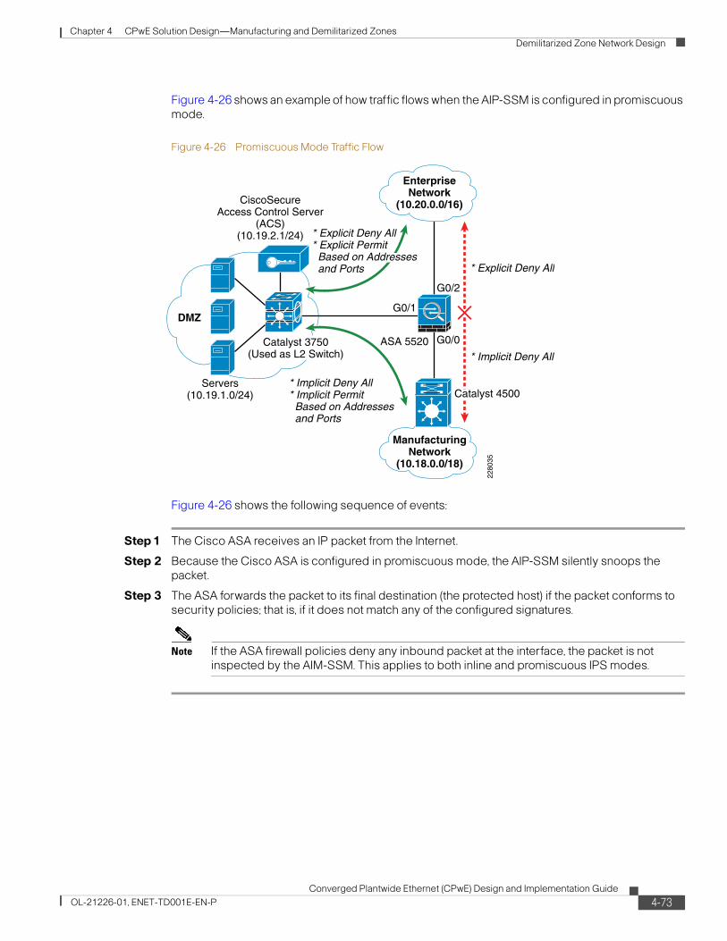
Chapter 4 CPwE Solution Design—Manufacturing and Demilitarized Zones Demilitarized Zone Network Design
Figure 4-26 shows an example of how traffic flows when the AIP-SSM is configured in promiscuous mode.
Figure 4-26 Promiscuous Mode Traffic Flow
Figure 4-26 shows the following sequence of events:
Step 1 The Cisco ASA receives an IP packet from the Internet.
Step 2 Because the Cisco ASA is configured in promiscuous mode, the AIP-SSM silently snoops the packet.
Step 3 The ASA forwards the packet to its final destination (the protected host) if the packet conforms to security policies; that is, if it does not match any of the configured signatures.
Note If the ASA firewall policies deny any inbound packet at the interface, the packet is not inspected by the AIM-SSM. This applies to both inline and promiscuous IPS modes.
2280
35
G0/1
G0/2
* Explicit Deny All
* Implicit Deny All* Implicit Permit Based on Addresses and Ports
* Implicit Deny All
G0/0
DMZ
Servers(10.19.1.0/24)
ManufacturingNetwork
(10.18.0.0/18)
EnterpriseNetwork
(10.20.0.0/16)CiscoSecureAccess Control Server
(ACS)(10.19.2.1/24)
Catalyst 3750(Used as L2 Switch)
ASA 5520
Catalyst 4500
* Explicit Deny All* Explicit Permit Based on Addresses and Ports
4-73Converged Plantwide Ethernet (CPwE) Design and Implementation Guide
OL-21226-01, ENET-TD001E-EN-P

Chapter 4 CPwE Solution Design—Manufacturing and Demilitarized Zones Demilitarized Zone Network Design
4-74Converged Plantwide Ethernet (CPwE) Design and Implementation Guide
OL-21226-01, ENET-TD001E-EN-P

Converged Plantwide Ethernet (CPwOL-21226-01, ENET-TD001E-EN-P
C H A P T E R 5
Implementing and Configuring the Cell/Area ZoneOverviewThis chapter outlines the configurations and configuration options to implement the recommendations and best practices described in Chapter 3, “CPwE Solution Design—Cell/Area Zone.” The Cell/Area zone is where the Industrial Automation and Control System (IACS) end-devices connect into the Cell/Area IACS network. Careful planning is required to achieve the optimal design from both the Cell/Area IACS network and IACS device perspective. This chapter provides implementation and configuration guidance on both IACS devices, in particular EtherNet/IP-based devices, and the Cell/Area IACS network infrastructure.
This chapter covers the following:
• Implementation of the Cell/Area IACS network when deploying industrial Ethernet switches for the Cell/Area zone
• Implementing EtherNet/IP network modules when deploying the key IACS end-devices for the Cell/Area zone
Implementing the Cell/Area IACS NetworkThe following sections detail the network configurations for EtherNet/IP devices within the Cell/Area zone such as I/O and HMI. It is important that a thorough design process be completed. This chapter assumes implementation of the key recommendations from Chapter 3, “CPwE Solution Design—Cell/Area Zone.” Where options are available, for example between network resiliency protocols, implementation guidance is provided for each supported option. The configuration details outlined below (e.g., VLAN numbers, hostnames, port numbers, etc.) are merely examples and should be adjusted accordingly to a particular plant IACS standards and environment.
This section provides the following:
• An overview of the Cell/Area IACS network implementation, including key tools and review of the recommendations from Chapter 3, “CPwE Solution Design—Cell/Area Zone.”
• Implementation steps for deploying an industrial Ethernet switch.
5-1E) Design and Implementation Guide
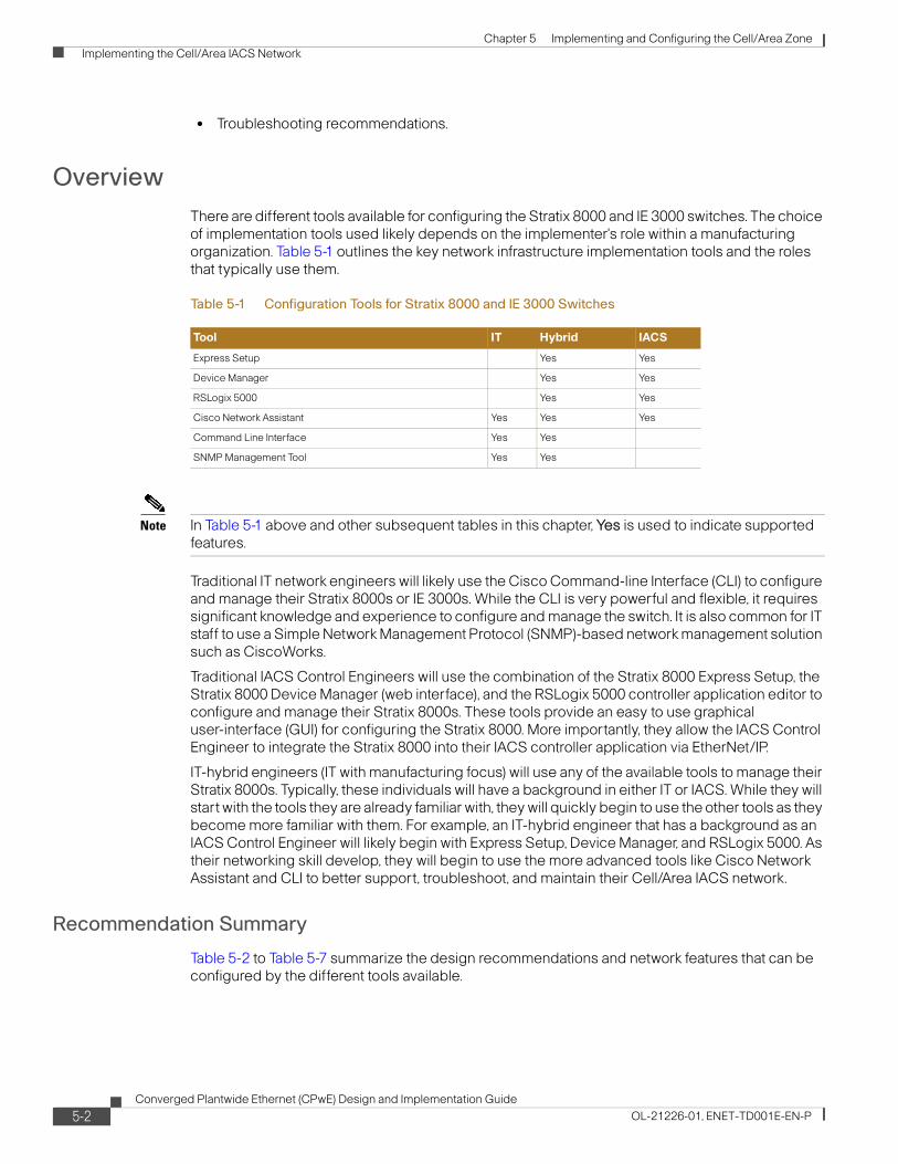
Chapter 5 Implementing and Configuring the Cell/Area Zone Implementing the Cell/Area IACS Network
• Troubleshooting recommendations.
OverviewThere are different tools available for configuring the Stratix 8000 and IE 3000 switches. The choice of implementation tools used likely depends on the implementer's role within a manufacturing organization. Table 5-1 outlines the key network infrastructure implementation tools and the roles that typically use them.
Note In Table 5-1 above and other subsequent tables in this chapter, Yes is used to indicate supported features.
Traditional IT network engineers will likely use the Cisco Command-line Interface (CLI) to configure and manage their Stratix 8000s or IE 3000s. While the CLI is very powerful and flexible, it requires significant knowledge and experience to configure and manage the switch. It is also common for IT staff to use a Simple Network Management Protocol (SNMP)-based network management solution such as CiscoWorks.
Traditional IACS Control Engineers will use the combination of the Stratix 8000 Express Setup, the Stratix 8000 Device Manager (web interface), and the RSLogix 5000 controller application editor to configure and manage their Stratix 8000s. These tools provide an easy to use graphical user-interface (GUI) for configuring the Stratix 8000. More importantly, they allow the IACS Control Engineer to integrate the Stratix 8000 into their IACS controller application via EtherNet/IP.
IT-hybrid engineers (IT with manufacturing focus) will use any of the available tools to manage their Stratix 8000s. Typically, these individuals will have a background in either IT or IACS. While they will start with the tools they are already familiar with, they will quickly begin to use the other tools as they become more familiar with them. For example, an IT-hybrid engineer that has a background as an IACS Control Engineer will likely begin with Express Setup, Device Manager, and RSLogix 5000. As their networking skill develop, they will begin to use the more advanced tools like Cisco Network Assistant and CLI to better support, troubleshoot, and maintain their Cell/Area IACS network.
Recommendation Summary
Table 5-2 to Table 5-7 summarize the design recommendations and network features that can be configured by the different tools available.
Table 5-1 Configuration Tools for Stratix 8000 and IE 3000 Switches
Tool IT Hybrid IACS
Express Setup Yes Yes
Device Manager Yes Yes
RSLogix 5000 Yes Yes
Cisco Network Assistant Yes Yes Yes
Command Line Interface Yes Yes
SNMP Management Tool Yes Yes
5-2Converged Plantwide Ethernet (CPwE) Design and Implementation Guide
OL-21226-01, ENET-TD001E-EN-P
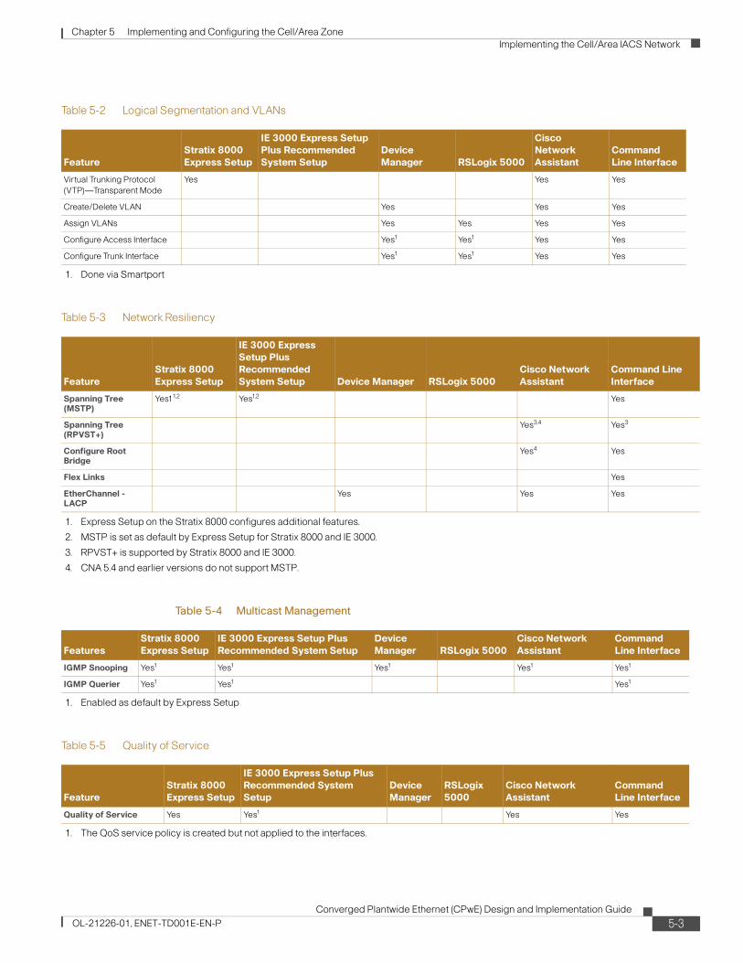
Chapter 5 Implementing and Configuring the Cell/Area Zone Implementing the Cell/Area IACS Network
Table 5-2 Logical Segmentation and VLANs
FeatureStratix 8000 Express Setup
IE 3000 Express Setup Plus Recommended System Setup
Device Manager RSLogix 5000
Cisco Network Assistant
Command Line Interface
Virtual Trunking Protocol (VTP)—Transparent Mode
Yes Yes Yes
Create/Delete VLAN Yes Yes Yes
Assign VLANs Yes Yes Yes Yes
Configure Access Interface Yes1
1. Done via Smartport
Yes1 Yes Yes
Configure Trunk Interface Yes1 Yes1 Yes Yes
Table 5-3 Network Resiliency
FeatureStratix 8000 Express Setup
IE 3000 Express Setup Plus Recommended System Setup Device Manager RSLogix 5000
Cisco Network Assistant
Command Line Interface
Spanning Tree (MSTP)
Yes11,2
1. Express Setup on the Stratix 8000 configures additional features.
2. MSTP is set as default by Express Setup for Stratix 8000 and IE 3000.
Yes1,2 Yes
Spanning Tree (RPVST+)
Yes3,4 Yes3
3. RPVST+ is supported by Stratix 8000 and IE 3000.
Configure Root Bridge
Yes4
4. CNA 5.4 and earlier versions do not support MSTP.
Yes
Flex Links Yes
EtherChannel - LACP
Yes Yes Yes
Table 5-4 Multicast Management
FeaturesStratix 8000 Express Setup
IE 3000 Express Setup Plus Recommended System Setup
Device Manager RSLogix 5000
Cisco Network Assistant
Command Line Interface
IGMP Snooping Yes1
1. Enabled as default by Express Setup
Yes1 Yes1 Yes1 Yes1
IGMP Querier Yes1 Yes1 Yes1
Table 5-5 Quality of Service
FeatureStratix 8000 Express Setup
IE 3000 Express Setup Plus Recommended System Setup
Device Manager
RSLogix 5000
Cisco Network Assistant
Command Line Interface
Quality of Service Yes Yes1
1. The QoS service policy is created but not applied to the interfaces.
Yes Yes
5-3Converged Plantwide Ethernet (CPwE) Design and Implementation Guide
OL-21226-01, ENET-TD001E-EN-P

Chapter 5 Implementing and Configuring the Cell/Area Zone Implementing the Cell/Area IACS Network
Table 5-6 Management, Monitoring, and Security
FeatureStratix 8000 Express Setup
IE 3000 Express Setup Plus Recommended System Setup Device Manager RSLogix 5000
Cisco Network Assistant
Command Line Interface
Enable Secret Yes Yes Yes Yes Yes
Line Passwords Yes Yes1
1. Express Setup on the IE 3000 does not enable the password encryption service.
Yes Yes
CIP Security Yes Yes2
2. Device Manager on the IE 3000 cannot set the CIP Security password.
Yes
Local Passwords Yes Yes
AAA Yes
Telnet Yes Yes3
3. Telnet is a optional configuration in Express Setup.
Yes
SSH Yes4
4. IE 3000 only. Requires the LAN-base feature set.
HTTP Yes Yes Yes
HTTPS Yes4
Common Industrial Protocol (CIP)
Yes Yes5
5. The IE 3000 enables CIP but does not enable CIP Security.
Yes
Simple Network Management Protocol (SNMP)
Yes6
6. Express Setup on the Stratix 8000 includes additional configuration options.
Yes7
7. Device Manager can be used enable/disable SNMP an add SNMPv2 community strings.
Yes Yes
SNMPv3 Yes4
Notification Banner Yes
Logging Yes Yes
Alarm Profile Yes8
8. Express Setup on the IE 3000 uses a simplified alarm profile.
Yes Yes
Table 5-7 Misc Features
FeatureStratix 8000 Express Setup
IE 3000 Express Setup Plus Recommended System Setup Device Manager RSLogix 5000
Cisco Network Assistant
Command Line Interface
CIP Enable Yes Yes
Error Disable Yes1
1. Express Setup on the Stratix 8000 includes additional configuration options.
Yes Yes
Precision Time Protocol (IEEE 1588 PTP)
Yes Yes Yes Yes2
2. RSLogix 5000 does not allow you to change the clock mode (transparent, boundary, or forward)
Yes
Unidirectional Link Detection (UDLD)
Yes Yes Yes
Assign Smartport Yes Yes Yes
5-4Converged Plantwide Ethernet (CPwE) Design and Implementation Guide
OL-21226-01, ENET-TD001E-EN-P

Chapter 5 Implementing and Configuring the Cell/Area Zone Implementing the Cell/Area IACS Network
Configuration Tools
This section outlines the key configuration tools that can be used to configure and maintain the Stratix 8000 or IE 3000 industrial Ethernet switches.
Express Setup
Express Setup is used to load initial configuration, IP address, and passwords into a switch that is in an out-of-box state. Express Setup uses Device Manager, referenced below, to apply the switch management IP address and password.
For step-by-step instructions on running Express Setup, see the following links:
• Stratix 8000 Ethernet Managed Switches Installation Instructions
http://literature.rockwellautomation.com/idc/groups/literature/documents/in/1783-in005_-en-p.pdf
• Cisco IE 3000 Switch Getting Started Guide http://cco.cisco.com/en/US/docs/switches/lan/cisco_ie3000/hardware/quick/guide/ie3000_gsg.html
The Stratix 8000 Express Setup enables the IACS Control Engineer to configure the switch for an EtherNet/IP IACS network without knowing or using the CLI. The IE 3000 Express Setup only provides a basic switch configuration and does not apply an EtherNet/IP IACS network-specific configuration. The IE 3000 includes a Recommended System Setup option in the Smartport configuration page. Checking this box applies many of the optimizations found on the Stratix 8000. In this chapter, any further references to Express Setup on an IE 3000 assume that the Recommended System Setup option has been applied.
Once Express Setup is complete, further configuration and management of the switch can be done using one of the following options, keeping in mind the feature details noted in the tables above:
• Device Manager Web-interface
• RSLogix 5000 controller application software, version 16 or later
• Cisco Network Assistant (CNA), version 5.4 or later
• Command-line interface (CLI)
• SNMP management applications such as CiscoWorks
5-5Converged Plantwide Ethernet (CPwE) Design and Implementation Guide
OL-21226-01, ENET-TD001E-EN-P

Chapter 5 Implementing and Configuring the Cell/Area Zone Implementing the Cell/Area IACS Network
Figure 5-1 Stratix 8000 and IE 3000 Device Managers
5-6Converged Plantwide Ethernet (CPwE) Design and Implementation Guide
OL-21226-01, ENET-TD001E-EN-P

Chapter 5 Implementing and Configuring the Cell/Area Zone Implementing the Cell/Area IACS Network
Figure 5-2 Stratix 8000 and IE 3000 Device Managers
Device Manager
The Device Manager is the Web-based configuration interface for the Stratix 8000 and IE 3000. It allows the implementer to easily implement advanced configurations consistently across the Cell/Area IACS network.
Device Manager can be used to configure several advanced configuration options such as the following:
• Smartports, discussed in the “Smartports” section on page D-10
• Port Settings (Description, Enable, Speed, Duplex, Auto-MDIX, and MediaType)
• VLANs
• EtherChannels (IEEE Link Aggregation Control Protocol - LACP)
• Dynamic Host Configuration Protocol (DHCP) Server
• IEEE 1588 Precision Time Protocol (PTP)
• Resilient Ethernet Protocol (REP)
• Simple Network Management Protocol (SNMP)
5-7Converged Plantwide Ethernet (CPwE) Design and Implementation Guide
OL-21226-01, ENET-TD001E-EN-P

Chapter 5 Implementing and Configuring the Cell/Area Zone Implementing the Cell/Area IACS Network
Figure 5-3 Stratix 8000 and IE 3000 Device Managers
The Device Manager also provides the following basic monitoring and management capabilities:
• Utilization Trends
• Port Status
• Port Statistics
• Alert Log
• CIP Status
• REP Topology
• Diagnostic Test
• IOS Upgrade
• Reboot
• Restore to Factory Defaults
For information on how to configure the Stratix 8000 switch using Device Manager, see the Stratix 8000 Ethernet Managed Switches Software User Manual at the following URL: http://literature.rockwellautomation.com/idc/groups/literature/documents/um/1783-um003_-en-e.pdf
For information on how to configure the IE 3000 switch using Device Manager, see the IE 3000 Getting Started Guide at the following URL: http://www.cisco.com/en/US/docs/switches/lan/cisco_ie3000/hardware/quick/guide/ie3000_gsg.html
RSLogix 5000
The Stratix 8000 switch is a CIP-enabled EtherNet/IP device designed to integrate into the Rockwell Automation Integrated Architecture. The Stratix 8000 comes with an Add-on Profile (AOP) for RSLogix 5000. AOP allows the Stratix 8000 to be integrated into the Rockwell Automation Logix Programmable Automation Controller (PACTM) project. Once added to the project, the Stratix 8000 switch appears in the I/O tree like any other EtherNet/IP device.
5-8Converged Plantwide Ethernet (CPwE) Design and Implementation Guide
OL-21226-01, ENET-TD001E-EN-P

Chapter 5 Implementing and Configuring the Cell/Area Zone Implementing the Cell/Area IACS Network
The AOP enables controller tags to monitor the status of the switch ports and the health status of the switch itself. These tags can be incorporated into the RSLogix 5000 project to monitor the status of the Cell/Area IACS network.
The AOP also enables the ability to configure the Stratix 8000 directly from RSLogix 5000, such as assigning Smartport and port traffic thresholds. Any configuration changes made via RSLogix 5000 are automatically saved to the Compact Flash card. In addition, the Stratix 8000 configuration can be uploaded into an RSLogix 5000 project and be saved as a part of the native RSLogix 5000 project. The Stratix 8000 configuration can also be exported from RSLogix 5000 into a file format that can be imported into other RSLogix 5000 projects. This export/import feature provides for quick reuse of testing and proven Stratix 8000 configurations between RSLogix 5000 applications.
Although RSLogix 5000 can assign individual ports to VLANs, other tools must be used to create and configure VLANs such as Device Manager. Device Manager is also used to configure Resilient Ethernet Protocol (REP), which is not included in this version of the solution. Multicast management and quality-of-service (QoS) are configured by default as part of the Stratix 8000 Express Setup.
The AOP can be used to configure the following features:
• CIP Connection to the Stratix 8000
• Port Settings (Enable, Speed, Duplex, Enable IEEE 1588 PTP)
• Smartports
• Native, Access, and Voice VLAN IDs
• Secure MAC Address (static port security)
• Storm Control Thresholds
In addition the following diagnostic information is available:
• Module Status
• Switch Status
• Port Status
• IEEE 1588 PTP Status
• Resiliency Protocol Status
• CIP Status
For information on how to configure the Stratix 8000 switch using the RSLogix 5000 AOP, see the Stratix 8000 Ethernet Managed Switches Software User Manual at the following URL:
http://literature.rockwellautomation.com/idc/groups/literature/documents/um/1783-um003_-en-e.pdf
5-9Converged Plantwide Ethernet (CPwE) Design and Implementation Guide
OL-21226-01, ENET-TD001E-EN-P

Chapter 5 Implementing and Configuring the Cell/Area Zone Implementing the Cell/Area IACS Network
Cisco Network Assistant
Cisco Network Assistant (CNA) is a PC-based network management solution. It allows the configuration, management, and troubleshooting of small-to-medium sized Cisco networks including the Stratix 8000. See Figure 5-4.
Figure 5-4 CNA
CNA provides the following functions:
• Supports networks that include up to 40 Cisco routers and switches, including the Stratix 8000
• Allows for the customization of configurations using a GUI, not CLI
• Backup and restore configuration files for all routers and switches
• Inventory reports including hostname, IP address, model, and IOS version
• Event notification
• IOS upgrades
• Network utilization reports
CNA is a free download from the following URL: http://www.cisco.com/go/cna
Note At the time of the writing of this Design and Implementation Guide (DIG), CNA version 5.4 does not support MSTP.
5-10Converged Plantwide Ethernet (CPwE) Design and Implementation Guide
OL-21226-01, ENET-TD001E-EN-P

Chapter 5 Implementing and Configuring the Cell/Area Zone Implementing the Cell/Area IACS Network
Command-Line Interface (CLI)
The CLI is the traditional IT method of configuring Cisco networking equipment. The CLI provides full access to all of the features and capabilities of the industrial Ethernet switches. The switches can be setup to allow CLI connections via the console port and Telnet sessions. The IE 3000 also provides the option to enable Secure Shell (SSH) for CLI access.
Some IT organizations may choose not to use Express Setup or the Smartports for the industrial Ethernet switches. It is important to understand the features recommended in this guide are enabled in the macros. If you choose not to use the macros, you need to incorporate many of these features into your existing template configurations. The contents of all of the Express Setup and Smartport macros can be viewed with the show parser macro commands.
Step-by-step instructions for configuring the industrial Ethernet switches via CLI can be found in the Cisco IE 3000 Software Configuration Guide at the following URL:
http://www.cisco.com/en/US/docs/switches/lan/cisco_ie3000/software/release/12.2_50_se/configuration/guide/ie3000scg.html
A full list of CLI commands related to the industrial Ethernet switches can be found in Cisco IE 3000 Switch Command Reference at the following URL: http://www.cisco.com/en/US/docs/switches/lan/cisco_ie3000/software/release/12.2_50_se/command/reference/ie3000cr.html.
Compact Flash Card
The industrial Ethernet switches come with a removable compact flash card. The switch stores the Internetworking Operating System (IOS) and the startup configuration on the compact flash card. In the event of a hardware failure, the compact flash card can be installed in the replacement switch. The replacement switch will boot using the IOS version and configuration stored on the card. No additional work is needed to restore the network.
Configuration changes made via the Device Manager or RSLogix 5000 are automatically saved to the compact flash card. Configuration changes made via the CLI or CNA must be manually saved to the compact flash card.
Smartports
Smartports are predefined configuration macros that were developed by Cisco and Rockwell Automation to simplify implementation of the switch for EtherNet/IP IACS networks. Smartports represent the joint design, testing, and implementation experience with IACS networks from both organizations. Smartports may be used by any of the available configuration tools to configure a port for a specific type of device. These configurations enable the easy implementation of many of the advanced features outlined in this DIG. Smartports and Express Setup enable consistent and simplified application of advanced, IACS optimized switch configurations across Cell/Area IACS networks.
For example, the Stratix 8000 “Automation Device” Smartport enables the following settings and features:
• Sets the port to host mode
• Enables MAC flooding attack protection
• Sets the access VLAN number
• Enables the automation QoS policy
• Configures the interface's output queues
5-11Converged Plantwide Ethernet (CPwE) Design and Implementation Guide
OL-21226-01, ENET-TD001E-EN-P
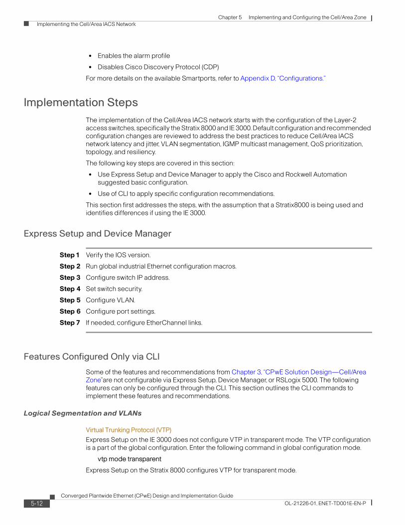
Chapter 5 Implementing and Configuring the Cell/Area Zone Implementing the Cell/Area IACS Network
• Enables the alarm profile
• Disables Cisco Discovery Protocol (CDP)
For more details on the available Smartports, refer to Appendix D, “Configurations.”
Implementation StepsThe implementation of the Cell/Area IACS network starts with the configuration of the Layer-2 access switches, specifically the Stratix 8000 and IE 3000. Default configuration and recommended configuration changes are reviewed to address the best practices to reduce Cell/Area IACS network latency and jitter, VLAN segmentation, IGMP multicast management, QoS prioritization, topology, and resiliency.
The following key steps are covered in this section:
• Use Express Setup and Device Manager to apply the Cisco and Rockwell Automation suggested basic configuration.
• Use of CLI to apply specific configuration recommendations.
This section first addresses the steps, with the assumption that a Stratix8000 is being used and identifies differences if using the IE 3000.
Express Setup and Device Manager
Step 1 Verify the IOS version.
Step 2 Run global industrial Ethernet configuration macros.
Step 3 Configure switch IP address.
Step 4 Set switch security.
Step 5 Configure VLAN.
Step 6 Configure port settings.
Step 7 If needed, configure EtherChannel links.
Features Configured Only via CLI
Some of the features and recommendations from Chapter 3, “CPwE Solution Design—Cell/Area Zone”are not configurable via Express Setup, Device Manager, or RSLogix 5000. The following features can only be configured through the CLI. This section outlines the CLI commands to implement these features and recommendations.
Logical Segmentation and VLANs
Virtual Trunking Protocol (VTP)
Express Setup on the IE 3000 does not configure VTP in transparent mode. The VTP configuration is a part of the global configuration. Enter the following command in global configuration mode.
vtp mode transparent
Express Setup on the Stratix 8000 configures VTP for transparent mode.
5-12Converged Plantwide Ethernet (CPwE) Design and Implementation Guide
OL-21226-01, ENET-TD001E-EN-P

Chapter 5 Implementing and Configuring the Cell/Area Zone Implementing the Cell/Area IACS Network
Availability and Network Resiliency
STP
• BPDU Guard
Express Setup on the IE 3000 does not configure BPDU Guard globally. BPDU Guard should be enabled globally on the switch. When BPDU Guard is applied globally, it will be enabled on all interfaces that have the spanning-tree portfast command enabled. Enter the following command in global configuration mode:
spanning-tree portfast bpduguard default
The Stratix 8000 enables BPDU Guard globally.
• BPDU Filter
Express Setup on the IE 3000 does not configure BPDU Filter globally.
BPDU Filter should be enabled globally on the switch. When BPDU Filter is applied globally, it will be enabled on all interfaces that have the spanning-tree portfast command enabled. Enter the following command in global configuration mode:
spanning-tree portfast bpdufilter default
The Stratix 8000 enables BPDU Filter globally.
• RPVST+
Where Cisco's RPVST+ implementation of the Spanning Tree Protocol (STP) is being used on the enterprise network switches, change the Spanning Tree configuration on the industrial Ethernet switches to RPVST+. The default for these switches is MSTP. The default for other Cisco IOS-based switches is RPVST+.
For more information on choosing a resiliency protocol, see Chapter 3, “CPwE Solution Design—Cell/Area Zone.” For information on configuring RPVST+ on the Stratix 8000 and IE 3000, see the IE 3000 Software Configuration Guide at the following URL:
http://www.cisco.com/en/US/docs/switches/lan/cisco_ie3000/software/release/12.2_50_se/configuration/guide/ie3000scg.html
• Root Bridge
The root bridge of the Spanning Tree network must be manually selected based on your topology. The distribution switches should be configured as the root bridges. To configure the primary root bridge, enter the following command in global configuration mode:
spanning-tree mst 0 root primary
To configure the secondary root bridge, enter the following command in global configuration mode:
spanning-tree mst 0 root secondary
These commands assume that you are using the default MSTP instance of 0.
For information on configuring the root bridge on a RPVST+ network on the Stratix 8000 and IE 3000, refer to the IE 3000 Software Configuration Guide at the following URL:
http://www.cisco.com/en/US/docs/switches/lan/cisco_ie3000/software/release/12.2_50_se/configuration/guide/ie3000scg.html
5-13Converged Plantwide Ethernet (CPwE) Design and Implementation Guide
OL-21226-01, ENET-TD001E-EN-P

Chapter 5 Implementing and Configuring the Cell/Area Zone Implementing the Cell/Area IACS Network
Flex Links
Flex Links are configured on the Stratix 8000 and the IE 3000 access switch. There are no configuration changes required to the distribution switches to use Flex Links. Flex Links requires that you designate an active and backup interface. Typically, interface gi1/1 is the active and interface gi1/2 is the backup. The following shows how to specify the configuration:
Straitx8000#config tEnter configuration commands, one per line. End with CNTL/Z.Stratix8000(config)#int gi1/1Stratix8000(config-if)#switchport backup interface gi1/2 multicast fast-convergeStratix8000(config-if)#
Security
Line Passwords
Express Setup on the IE 3000 does not enable the password encryption service. This means that the line passwords appear as clear text in the configuration. The password encryption service is enabled in the global configuration with the following command:
service password-encryption
Express Setup on the Stratix 8000 enables the password encryption service.
CIP Security
Express Setup on the IE 3000 does not enable CIP or configure a CIP security password. Enabling CIP without a CIP security password, any controller can connect to the switch and make changes to the configuration. The CIP security password can be configured with the following global configuration command:
cip security password password
Express Setup on the Stratix 8000 configures the CIP security password.
Notification Banner
A login banner should be configured to display at all logins. As part of a security policy, it is necessary to ensure that network resources are clearly identified as being off limit to the casual visitor. The contents of the banner should be discussed with your legal council. There are several methods of enabling the banner, including the banner motd, banner login, banner incoming, and banner exec commands. The banner login global configuration command should be used for the initial login banner.
Logging
Express Setup on the IE 3000 does not configure the logging buffer size or the time stamping service.
logging buffered 16384service timestamps debug datetime msec localtime show-timezoneservice timestamps log datetime msec localtime show-timezone
Express Setup on the Stratix 8000 configures the logging buffer and the time stamping service.
Additional logging features, such as logging to an external syslog server, are available. For more details on the IE switches, see IE 3000 Software Configuration Guide at the following URL:
http://cco.cisco.com/en/US/docs/switches/lan/cisco_ie3000/software/release/12.2_50_se/configuration/guide/ie3000scg.html
5-14Converged Plantwide Ethernet (CPwE) Design and Implementation Guide
OL-21226-01, ENET-TD001E-EN-P

Chapter 5 Implementing and Configuring the Cell/Area Zone Implementing the Cell/Area IACS Network
Authentication, Authorization, and Accounting (AAA)
AAA is the preferred method of securing access to the network switches. AAA relies on an external AAA server such as Cisco Secure ACS. Configuring AAA is beyond the scope of this guide. For more information, refer to the “Enforce AAA” section in “Chapter 2, Network Foundation Protection” of the Cisco SAFE Reference Guide at the following URL:
http://www.cisco.com/en/US/docs/solutions/Enterprise/Security/SAFE_RG/chap2.html
SSH
SSH should be enabled to encrypt management traffic to the IE 3000. SSH does not work with line passwords. It requires that either local usernames and passwords or AAA is configured. There are four parts to configuring SSH:
1. In order to use SSH, the switch must be using an IOS image capable of cryptography. The cryptography image for Cisco switches is available for download at http://www.cisco.com.
Note Some platforms may require the selection of the cryptography image at the time of purchase or pay a fee to upgrade the feature set to include the cryptography.
2. SSH requires the use of usernames and passwords for authentication. To accomplish this, the switch must be configured to use an AAA server like TACACS+ for authentication. If an AAA server is not available on the network, local usernames, and passwords can be used as an alternative.
For more information, refer to the “Protect Local Passwords” section in “Chapter 2, Network Foundation Protection” of the Cisco SAFE Reference Guide at the following URL:
http://www.cisco.com/en/US/docs/solutions/Enterprise/Security/SAFE_RG/chap2.html
3. SSH must be configured in the global configuration. SSH requires that the switch is configured with a hostname and a domain name. The hostname is set with the hostname hostname global configuration command. The domain name is configured with the ip domain-name domain-name global configuration command. Once the hostname and domain names are set, a RSA key pair must be generated. The crypto key generate rsa global configuration command generates the RSA key pair and enables SSH on the switch.
4. The VTY lines must be configured to use SSH. By default, the VTYs accepts connections via both Telnet and SSH. The transport input ssh configuration command allows you to limit access to SSH. This command disables Telnet access to the switch. The transport input all command allows both SSH and Telnet access. The transport input telnet command allows only Telnet access.
HTTPS
HTTPS should be enabled to encrypt management traffic to the switch. At this time, the Stratix 8000 does not support HTTPS. In order to use HTTPS, the switch must use an IOS image capable of cryptography. The cryptography image for Cisco switches is available for download at the following URL: http://www.cisco.com.
Note Some platforms may require the selection of cryptography image at the time of purchase or pay a fee to upgrade the feature set to include the cryptography.
5-15Converged Plantwide Ethernet (CPwE) Design and Implementation Guide
OL-21226-01, ENET-TD001E-EN-P

Chapter 5 Implementing and Configuring the Cell/Area Zone Implementing the Cell/Area IACS Network
Once the proper IOS feature set is installed, the HTTPS server should be enabled with the ip http secure-server global configuration command. After the HTTPS server is enabled, the HTTP server should be disabled with the no ip http server global configuration command. In addition, HTTPS requires that Telnet is enabled on the VTY lines.
Miscellaneous Features
Error Disable
Express Setup on the IE 3000 does not fully configure the error-disable feature. The following error-disable settings are recommended for an Cell/Area IACS network. Error-disable is configured in the global configuration.
errdisable recovery cause udlderrdisable recovery cause bpduguarderrdisable recovery cause security-violationerrdisable recovery cause channel-misconfigerrdisable recovery cause pagp-flaperrdisable recovery cause dtp-flaperrdisable recovery cause link-flaperrdisable recovery cause sfp-config-mismatcherrdisable recovery cause gbic-invaliderrdisable recovery cause psecure-violationerrdisable recovery cause port-mode-failureerrdisable recovery cause dhcp-rate-limiterrdisable recovery cause mac-limiterrdisable recovery cause vmpserrdisable recovery cause storm-controlerrdisable recovery cause arp-inspectionerrdisable recovery cause loopbackerrdisable recovery cause small-frameerrdisable recovery interval 30
Express Setup on the Stratix 8000 configures Error Disable.
5-16Converged Plantwide Ethernet (CPwE) Design and Implementation Guide
OL-21226-01, ENET-TD001E-EN-P

Chapter 5 Implementing and Configuring the Cell/Area Zone Implementing the EtherNet/IP Network Modules
Implementing the EtherNet/IP Network ModulesThis section focuses on the configuration of the EtherNet/IP network devices. The following tools are required:
• RSLinx Classic (2.54.00.11 CPR 9 SR 1 or greater)
• RSLogix 5000 (v16 or greater)
• Stratix 8000 Add-on-Profile (AOP) (v3. 3.01.008 or greater)
• Stratix 8000 Express Setup (12.2(50)SE2 or greater)
Overview
EIP Network Module Implementation Tools
RSLinx Classic
RSLinx Classic is a communication server that allows you to browse and communicate with EtherNet/IP devices on the Cell/Area IACS network. RSLinx Classic includes drivers to communicate with many different types of devices and several different network protocols. In most cases, RSLinx Classic should be configured to use the EtherNet/IP driver. The EtherNet/IP driver can be configured for local and remote browsing. Local browsing sends a discovery broadcast to devices on the local Ethernet network. This is useful when you need to discover devices on the local link. To configure local browsing, select the appropriate interface from the list. See Figure 5-5.
Figure 5-5 RSLinx Classic EtherNet/IP Driver Configuration Screen
Remote browsing sends a discovery broadcast directed at a specific IP subnet. This is useful when you need to browse devices in a specific Cell/Area zone from the Manufacturing zone. To configure the EtherNet/IP driver for remote browsing, enter the target subnet and mask. See Figure 5-6.
5-17Converged Plantwide Ethernet (CPwE) Design and Implementation Guide
OL-21226-01, ENET-TD001E-EN-P

Chapter 5 Implementing and Configuring the Cell/Area Zone Implementing the EtherNet/IP Network Modules
Figure 5-6 RSLinx Classic EtherNet/IP Driver Configuration Screen
The remote browse function uses a feature called IP-directed broadcast. Most Cisco Layer-3 switches and routers disable directed broadcasts by default. Directed broadcasts can be enabled with the ip directed-broadcast interface configuration command. This command needs to be applied to all routed interfaces for the subnets and Cell/Area zones you need to browse.
There is a second option for browsing EtherNet/IP devices with RSLinx Classic. The Ethernet devices driver supports manual entry of IP addresses to browse (see Figure 5-7). There is a second option for browsing EtherNet/IP devices with RSLinx Classic. The Ethernet devices driver supports manual entry of IP addresses to browse.
Figure 5-7 RSLinx Classic AB_Ethernet Driver Configuration Screen
5-18Converged Plantwide Ethernet (CPwE) Design and Implementation Guide
OL-21226-01, ENET-TD001E-EN-P

Chapter 5 Implementing and Configuring the Cell/Area Zone Implementing the EtherNet/IP Network Modules
EtherNet/IP Interface Configuration
• IP Configuration
• Link Speed and Duplex Mode
IP Configuration
EtherNet/IP uses the Internet Protocol (IP) to communicate between modules. The following are options for configuring the IP address of the module:
• Mechanical rotary switches
• DHCP/BOOTP
• CIP messaging
Table 5-8 provides the configuration parameters for the EtherNet/IP modules.
All EtherNet/IP modules must have a unique IP address on the network. The network mask is used to determine which subnet the EtherNet/IP module is on. The gateway address is used when the EtherNet/IP module needs to communicate with an TCP/IP device that is located on another subnet. The network mask is used to determine if the destination host is on the local or a remote subnet. If the destination is on the local subnet, the EtherNet/IP module sends the packet directly to the destination. If the destination is on a remote subnet, the EtherNet/IP module forwards the packet to the gateway. The gateway then forwards the packet to the appropriate subnet.
Most EtherNet/IP network implementations require that the gateway address is statically configured on the module. Some implementations may choose to use DNS name resolution. If your EtherNet/IP network implementation requires the use of DNS, the primary name server, secondary name server, domain name, and hostname field should be completed. This DIG does not cover the use of DNS in the EtherNet/IP network.
In most applications, the IP addresses of EtherNet/IP I/O devices are statically entered into the application. Because of this, it is important that the module’s address always matches the address entered in the application.
Mechanical Rotary Switches
Many Rockwell Automation EtherNet/IP devices have three rotary switches for configuring the IP address. These switches are used to set the last octet of the IP address. The advantage of using the rotary switches is that maintenance staff can replace the module without needing a computer or knowledge of IP addressing. This greatly reduces mean-time-to-repair (MTTR). See Table 5-9.
Table 5-8 Configuration Parameters for EtherNet/IP Modules
Parameter Description Required Recommended Optional
IP Address The IP address of the EtherNet/IP module Yes
Network Mask The network mask of the EtherNet/IP module Yes
Gateway Address The default gateway address of the EtherNet/IP module Yes
Primary Name Server The IP address of the primary DNS server Yes
Secondary Name Server The IP address of the secondary DNS server Yes
Domain Name The DNS domain name of the EtherNet/IP module Yes
Host Name The host name of the EtheNet/IP module Yes
5-19Converged Plantwide Ethernet (CPwE) Design and Implementation Guide
OL-21226-01, ENET-TD001E-EN-P

Chapter 5 Implementing and Configuring the Cell/Area Zone Implementing the EtherNet/IP Network Modules
While the rotary switches work well in a small isolated network such as a machine or line, they are not effective in larger plantwide EtherNet/IP networks. The EtherNet/IP modules do not allow the configuration of a default gateway when using the rotary switches. This prevents the module from communicating with any devices outside of the local 192.168.1.0/24 subnet.
Setting the rotary switches to a value other than 001 to 254 or 888 sets the module to have its IP address configured via software. This is the default configuration.
DHCP/BOOTP
The Dynamic Host Configuration Protocol (DHCP) or the Bootstrap Protocol (BootP) can be used to assign the IP address from a server or workstation. This is the default setting for modules that do not have rotary switches. If the module has rotary switches any number other than 001 to 254, 888 will configure the device to use DHCP/BootP.
On boot up, the module sends a request for an IP address. A BootP server assigns an address to the module based on its MAC address. Since the address is assigned by the MAC address, BootP guarantees that the device will always get the same IP address. However, if the device fails and is replaced the BootP table must be updated with the new MAC address. The replacement device will not get its assigned address until the BootP table is updated.
A DHCP server has the ability to assign the IP address based on a pool of available addresses. This is convenient in the Enterprise zone where the IP address of the client is not critical. DCHP also has the ability to assign IP addresses based on a Client-ID. The default Client-ID is the MAC address of the host. This means that the DCHP server can be setup to statically map an IP address to a MAC address like BootP.
Again, it is important that IP addresses of the EtherNet/IP modules in the controller application are consistent within the Cell/Area zone. Because of this, it is recommended that the IP address is manually entered into the EtherNet/IP module. DHCP is commonly used to assign an initial address to that the module can be statically configured via CIP messaging.
CIP Messaging
The IP address of an EtherNet/IP module can be set using CIP messages. The two most common ways to set CIP messages are through RSLinx Classic or the RSLogix 5000 AOP for the EtherNet/IP module. The EtherNet/IP module must be reachable on the CIP network to set the IP address via CIP messaging. This can be done via EtherNet/IP, DeviceNet, ControlNet, RS232, or USB. See Figure 5-8.
Table 5-9 Mechanical Rotary Switches
Switch Setting IP Address
001 – 254 192.168.1.xyz
Where xyz is the values of switches x, y, and z
Subnet Mask: 255.255.255.0
Gateway Address: 0.0.0.0
888 Resets module to initial out of box settings. Do not use for normal operation
Any Other Value IP address configuration is controlled via software:
BootP
DHCP
User Entered
5-20Converged Plantwide Ethernet (CPwE) Design and Implementation Guide
OL-21226-01, ENET-TD001E-EN-P

Chapter 5 Implementing and Configuring the Cell/Area Zone Implementing the EtherNet/IP Network Modules
Figure 5-8 RSLinx Classic RSWho
The RSWho window allows you to browse the CIP devices on the CIP network. The IP address of an EtherNet/IP module can be set by right-clicking on the module and selecting Module Configuration. The Port Configuration tab allows you to configure the module to use DHCP/BootP or a static IP address. If you select a static address, you can enter the IP address, subnet mask, and default gateway for the module. Optionally, you can configure DNS-related information such as DNS servers and hostname. See Figure 5-9.
5-21Converged Plantwide Ethernet (CPwE) Design and Implementation Guide
OL-21226-01, ENET-TD001E-EN-P
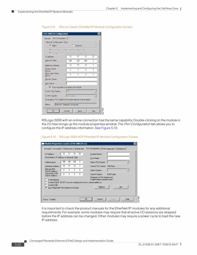
Chapter 5 Implementing and Configuring the Cell/Area Zone Implementing the EtherNet/IP Network Modules
Figure 5-9 RSLinx Classic EtherNet/IP Module Configuration Screen
RSLogix 5000 with an online connection has the same capability. Double-clicking on the module in the I/O tree brings up the module properties window. The Port Configuration tab allows you to configure the IP address information. See Figure 5-10.
Figure 5-10 RSLogix 5000 AOP EtherNet/IP Module Configuration Screen
It is important to check the product manuals for the EtherNet/IP modules for any additional requirements. For example, some modules may require that all active I/O sessions are stopped before the IP address can be changed. Other modules may require a power cycle to load the new IP address.
5-22Converged Plantwide Ethernet (CPwE) Design and Implementation Guide
OL-21226-01, ENET-TD001E-EN-P

Chapter 5 Implementing and Configuring the Cell/Area Zone Implementing the EtherNet/IP Network Modules
For more information, refer to the EtherNet/IP Modules in Logix5000 Control Systems User Manual at the following URL:
http://literature.rockwellautomation.com/idc/groups/literature/documents/um/enet-um001_-en-p.pdf
Link Speed and Duplex
In Chapter 3, “CPwE Solution Design—Cell/Area Zone,” the pros/cons of using auto-negotiate or setting the speed/duplex are discussed. If you choose not to use auto-negotiate or if the hardware does not support it, it is important to ensure that both sides of the link are using the same speed and duplex settings.
A good example of this is the Allen-Bradley 1756-EN2F ControlLogix EtherNet/IP Fiber Module. The 1756-EN2F does not support auto-negotiate and only operates at 100Mbps full-duplex. In order to use this module, the interface on the Stratix 8000 must be manually set to 100Mbps full-duplex to match the module.
5-23Converged Plantwide Ethernet (CPwE) Design and Implementation Guide
OL-21226-01, ENET-TD001E-EN-P

Chapter 5 Implementing and Configuring the Cell/Area Zone Implementing the EtherNet/IP Network Modules
5-24Converged Plantwide Ethernet (CPwE) Design and Implementation Guide
OL-21226-01, ENET-TD001E-EN-P
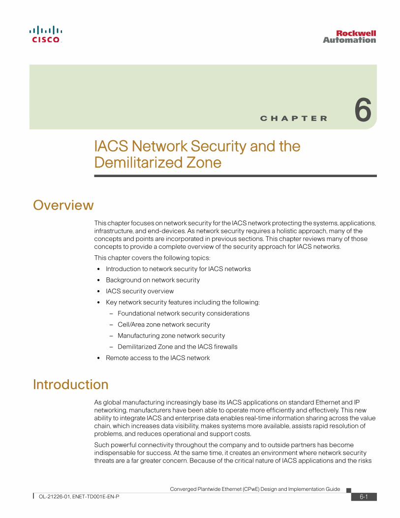
Converged Plantwide Ethernet (CPwOL-21226-01, ENET-TD001E-EN-P
C H A P T E R 6
IACS Network Security and the Demilitarized ZoneOverviewThis chapter focuses on network security for the IACS network protecting the systems, applications, infrastructure, and end-devices. As network security requires a holistic approach, many of the concepts and points are incorporated in previous sections. This chapter reviews many of those concepts to provide a complete overview of the security approach for IACS networks.
This chapter covers the following topics:
• Introduction to network security for IACS networks
• Background on network security
• IACS security overview
• Key network security features including the following:
– Foundational network security considerations
– Cell/Area zone network security
– Manufacturing zone network security
– Demilitarized Zone and the IACS firewalls
• Remote access to the IACS network
IntroductionAs global manufacturing increasingly base its IACS applications on standard Ethernet and IP networking, manufacturers have been able to operate more efficiently and effectively. This new ability to integrate IACS and enterprise data enables real-time information sharing across the value chain, which increases data visibility, makes systems more available, assists rapid resolution of problems, and reduces operational and support costs.
Such powerful connectivity throughout the company and to outside partners has become indispensable for success. At the same time, it creates an environment where network security threats are a far greater concern. Because of the critical nature of IACS applications and the risks
6-1E) Design and Implementation Guide

Chapter 6 IACS Network Security and the Demilitarized Zone Introduction
associated with them, it is more important than ever for manufacturers to implement a comprehensive network security strategy that protects while it enables access and integration to achieve efficiencies and complete visibility.
The Cisco and Rockwell Automation CPwE solution helps manufacturers moving to IACS applications based on standard Ethernet and IP to connect, integrate, and secure their systems to help ensure consistent and reliable performance. The Cisco and Rockwell Automation recommended security model enables successful deployment of complex technologies in a manufacturing environment, meeting the needs of the IACS systems as well as enterprise business applications. This security model pulls from the best of Cisco security and Rockwell Automation security and approaches to deliver a cohesive and optimized security for IACS networks.
Cisco SAFEThe Cisco SAFE provides the design and implementation guidelines for building secure and reliable network infrastructures that are resilient to both well-known and new forms of attacks. Cisco SAFE takes a defense-in-depth approach, where multiple layers of protection are strategically located throughout the network, but under a unified strategy. Event and posture information is shared for greater visibility and response actions are coordinated under a common control strategy. The Cisco SAFE uses modular designs that accelerate deployment and that facilitate the implementation of new solutions and technologies as business needs evolve. This modularity extends the useful life of existing equipment, protecting capital investments. At the same time, the designs incorporate a set of tools to facilitate day-to-day operations, reducing overall operational expenditures.
This solution applies the SAFE model and many of the SAFE recommendations for the security of the IACS. This solution applies the relevant recommendations from “Chapter 2, Network Foundation Protection” and “Chapter 5, Enterprise Campus” of the Cisco SAFE Reference Guide (http://www.cisco.com/en/US/docs/solutions/Enterprise/Security/SAFE_RG/SAFE_rg.html). There are many other important guidelines in that document, but not necessarily relevant to the IACS network. For example, the section on the Corporate Access/DMZ are key considerations for the remote access capability outlined in this solution, but is usually the responsibility of the corporate IT organization.
Rockwell Automation Integrated ArchitectureProtecting manufacturing assets requires a defense-in-depth security approach, as depicted in Figure 6-1, that addresses internal and external security threats. This approach uses multiple layers of defense (physical and electronic) at separate manufacturing levels by applying policies and procedures that address different types of threats. For example, multiple layers of network security protect networked assets, data, and end points, and multiple layers of physical security to help protect high value assets. No single technology or methodology can fully secure IACS applications.
In achieving a defense-in-depth approach, an operational process is required to establish and maintain the security capability. A security operational process includes the following:
• Identify priorities (e.g., availability, integrity, and confidentiality)
• Establish requirements (e.g., remote access must not impact IACS network traffic, etc.)
• Identify assets
• Identify potential internal and external threats and risks
• Understand capabilities required
6-2Converged Plantwide Ethernet (CPwE) Design and Implementation Guide
OL-21226-01, ENET-TD001E-EN-P

Chapter 6 IACS Network Security and the Demilitarized Zone Introduction
• Develop architecture
• Develop and implement manufacturing focused security policies
Designing and implementing a comprehensive manufacturing security model should serve as a natural extension to the manufacturing process. Manufacturers should not implement security as a bolt-on component to the manufacturing process.
In the Integrated Architecture approach, defense-in-depth layers for securing manufacturing assets include the following:
• Physical Security—This limits physical access of areas, control panels, devices, cabling, the control rooms and other locations to authorized personnel with provisions to escort and tracks visitors.
• Network Security—This includes the network infrastructure, such as firewalls with intrusion detection and intrusion prevention systems (IDS/IPS), and integrated protection of networking equipment such as switches and routers.
• Computer Hardening—This includes patch management and antivirus software as well as removal of unused applications, protocols and services.
• Application Security—This contains authentication, authorization and audit software.
• Device Hardening—This handles change management and restrictive access.
Figure 6-1 Rockwell Automation Security Defense-in-Depth Layered Security Model
Defense-in-Depth
Layered Security Model
Application
Device
Computer
Physical
Network
2279
44
6-3Converged Plantwide Ethernet (CPwE) Design and Implementation Guide
OL-21226-01, ENET-TD001E-EN-P

Chapter 6 IACS Network Security and the Demilitarized Zone Introduction
Relevant Standards and Frameworks
ISA-99 Industrial Automation and Control System Security
The ISA-99 Committee establishes standards, recommended practices, technical reports, and related information that defines procedures for implementing electronically secure IACS applications and security practices and assessing electronic security performance. Guidance is directed towards those responsible for designing, implementing, or managing IACS applications and shall also apply to manufacturers, system integrators, machine builders, security practitioners, and IACS vendors.
The committee's focus is to improve the confidentiality, integrity, and availability of IACS networks and to provide criteria for procuring and implementing IACS applications. Compliance with the Committee's guidance will improve IACS electronic security, and will help identify vulnerabilities and address them, thereby reducing the risk of compromising confidential information or causing IACS degradation or failure.
• ISA-99 published its Part 1 standard, ANSI/ISA-99.00.01-2007, Security for Industrial Automation and Control Systems: Concepts, Terminology and Models, in late 2007.
• ISA-99 completed its Part 2 standard, ANSI/ISA-99.02.01-2009, Security for Industrial Automation and Control Systems: Establishing an Industrial Automation and Control Systems Security Program on 13 January 2009.
This CPwE Design and Implementation Guide (DIG) identifies some key security concepts that manufacturers should put in place, but are not necessarily covered in this document, such as Security Maturity Model and a process to evaluation and improve a “Security Level” of the IACS. These concepts are not covered in this CPwE solution.
The ISA-99 standards identifies a wide range of security concepts, definitions, models, as well as a process and guidance to develop cyber-security management systems for an IACS. This CPwE solution aligns with the process and guidance recommended. The key points of alignment include the following:
1. The clearly demarked network zones: Enterprise (CPwE and ISA 99) with Levels 4 &5, the DMZ and the Manufacturing (CPwE) or Control (ISA99) zone with Levels 0 - 3 as depicted in section ANSI/ISA-99.02.01-2009 section A.3.3.4.2 Figure A.8
2. Support for a Demilitarized zone (DMZ). As stated in ANSI/ISA-99.02.01-2009 section A.3.3.4.2 Network segments and zones:
“For high risk IACS, the use of a DMZ in conjunction with a Control zone offers additional risk reduction opportunities between the low-security level Business zone and the high-security level Control zone. The security level for the DMZ is higher than the Business zone but less than the Control zone. The function of this zone is to eliminate or greatly reduce all direct communication between the Control zone and the Business/Enterprise zone.”
Additionally, the use cases where a DMZ is beneficial include the following:
• Minimize the number of people directly accessing control zone devices.
Historian servers are often accessed by people located on the site LAN in the business zone. Rather than locating the historian server in the Control zone and allowing direct access to this device from the Business/Enterprise zone by a large number of users, the security level of the Control zone can be maintained at a higher level if the historian server is located in the DMZ. CPwE recommends the use of a historian mirror located within the DMZ to replicate historian data between the CPwE Manufacturing and Enterprise zones.
• Provide greater security for important IACS devices.
6-4Converged Plantwide Ethernet (CPwE) Design and Implementation Guide
OL-21226-01, ENET-TD001E-EN-P
Chapter 6 IACS Network Security and the Demilitarized Zone Background
In the case of the historian server mentioned above, an option is to locate the historian on the site LAN where the majority of the users are located. This would reduce the number of people needing to access the PCN. However, since the business zone is a low-security level zone, the historian server would be subjected to a less secure environment. The potential for compromise of the server would be greater. The Cisco and Rockwell Automation CPwE does not recommend this approach.
• Compensate for patching delays.
The DMZ offers additional security protection to important IACS devices that cannot be patched as quickly while waiting for patch compatibility testing results from the application vendor.
• Provide improved security for the Control zone by moving management devices to a higher security level.
The DMZ is a good place to locate devices like anti-virus servers and patch management servers. These devices can be used to manage deployment of security modules to the control zone and DMZ devices in a more controlled manner without subjecting the high-security level control zone to direct connection to servers that may be communicating to hundreds of devices.”
3. The implementation of a firewall to segment the Manufacturing or Control, DMZ and Enterprise zones from one another as noted in Figure 4-22. Although not specifically clarified, this CPwE solution recommends placing the Remote Access Server (CPwE name) or Remote Operator Console (ISA 99 name) and Historian servers in the Manufacturing or Control zone so as to keep the IACS communication contained to that zone.
The scope of this section is not to analyze and compare the ISA-99 material with the CPwE DIG, but nonetheless, Cisco and Rockwell Automation support the process and have tried to align this solution with concepts, ideas, and recommendations from ISA-99.
BackgroundThis section is intended to give the reader some background and context to the security approach this CPwE solution promotes. As standard Ethernet and IP networking is still in a growth and adoption phase for many manufacturers, this background is intended to bring readers up to speed on key security concepts and considerations. Key topics include the following:
• Security principles maintained
• Challenges for network security specific to the IACS
• Key priorities for IACS security
• Review of the security requirements
• Description of IACS assets to be protected
• Overview of security threats to an IACS
• Impact considerations to determine level of IACS security
6-5Converged Plantwide Ethernet (CPwE) Design and Implementation Guide
OL-21226-01, ENET-TD001E-EN-P

Chapter 6 IACS Network Security and the Demilitarized Zone Background
Principles
Defense-in-Depth
In the CPwE, security is embedded throughout the IACS network by following a defense-in-depth approach, and to ensure the availability, integrity, confidentiality and of data, IACS applications, IACS endpoints, the IACS network and the plant and its personnel. For enhanced visibility and control, a rich set of security technologies and capabilities are deployed in multiple layers, but under a common strategy.
Modularity and Flexibility
The CPwE design blueprints follow a modular design where all components are described by functional roles rather than point platforms. The overall IACS network infrastructure is divided into functional modules, each one representing a distinctive aspect such as the campus and the network foundation. Functional modules are then subdivided into more manageable and granular functional layers and blocks (for example, access layer, infrastructure device access), each serving a specific role in the network. The modular designs result in added flexibility when it comes to deployment, allowing a phased implementation of modules as it best fits the plant's needs. The fact components are described by functional roles rather than point platforms facilitates the selection of the best platforms for given roles and their eventual replacement as technology and business needs evolve. Finally, the modularity of the designs also accelerates the adoption of new services and roles, extending the useful life of existing equipment and protecting previous capital investment.
Service Availability and Resiliency
The CPwE design blueprints incorporate several layers of resiliency considerations and technologies and device/component redundancy to eliminate single points of failure and to maximize the availability of the IACS network infrastructure. A resilient and available network is inherently less susceptible to security threats. This includes the use of redundant interfaces, backup modules, standby devices, topologically redundant paths and application of network resiliency protocols. In addition, the designs also use a wide set of features destined to make the IACS network more resilient to attacks and network failures.
Auditable Implementations
The CPwE designs accommodate a set of tools to measure and verify the operation and the enforcement of safeguards across the IACS network, providing a current view of the security posture of the network, and helping assess compliance to security policies, standards, and regulations.
Challenges of Industrial EnvironmentsIndustrial environments are especially sensitive to security threats due to the fact that system downtime, loss of critical data, and other potential consequences can have a devastating impact on manufacturers. Even outages and performance degradation are unacceptable in these real-time, on-demand environments. Manufacturing business success depends on continuous, ongoing manufacturing, and downtime is incredibly expensive.
6-6Converged Plantwide Ethernet (CPwE) Design and Implementation Guide
OL-21226-01, ENET-TD001E-EN-P

Chapter 6 IACS Network Security and the Demilitarized Zone Background
Today's movement toward commercial off-the-shelf (COTS) technologies—such as the Microsoft Windows operating system, Distributed Component Object Model, Ethernet and TCP/IP, and Internet-based applications—increases the risk. Ethernet and IP functionality provides great benefits in terms of visibility, efficiency, and cost-effectiveness, but it also exposes the manufacturer to a wider range of security threats, ranging from malicious code and attacks by hackers to performance issues due to unexpected traffic, network scans, or similar activities. Then too, as hackers become increasingly aggressive and sophisticated, and as disclosure of vulnerabilities occurs in real time, the time between the discovery and the exploitation of a COTS vulnerability is rapidly decreasing. While most security issues have been effectively managed in IT networks for several years, security has not typically been the focus of Control Engineers who design, deploy, and manage IACS networks.
The performance requirements of and IACS compound the challenge of securing IACS environments. To ensure consistent uptime and performance, these systems demand very low levels of latency, support of IACS network protocols, predictable performance, and high availability. At the same time, they often have patching limitations, and specialized network management considerations. Also, it is often important to provide guest and remote access to IACS applications and have visibility and integration of data between enterprise business and IACS applications. All these factors increase vulnerability and can affect the security tools that can be deployed.
Although it is tempting to conclude that IACS networks protected by a corporate firewall must be safe—and therefore immune to attacks on corporate mail and web servers—the situation is not that simple. Small security failures—an improperly secured wireless access point or a forgotten dial-up modem attached to a programmable automation controller for IACS applications, a personal computer, or even a remote access server directly connected to the IACS network—can provide access for a determined attacker. Intranet connections with business partners, suppliers, system integrators, or vendors within the plant can also provide ample opportunity for attackers to gain access without having to breach the Internet firewall or the firewall between the enterprise and IACS networks. Even IACS applications on their own isolated IACS network are at risk if users can access them. And once access is gained, attackers can find many familiar and largely vulnerable targets (namely, Windows-based workstations and servers) that can be compromised using existing tools and techniques.
These trends and issues are not unique to manufacturing. Organizations across many industries face similar challenges, particularly as hackers find new ways to exploit systems for financial gain. Manufacturing environments, like other embedded IACS applications, are especially at risk of attack since the cost of downtime is so high.
PrioritiesThe first step in developing an IACS network security approach is to define the secure environment's fundamental priorities, which will vary depending on the environment. This approach should be used for each security zone (such as an IACS network or a plant site IT network) across the enterprise to determine system needs and the best solution to support basic business requirements. These business necessities typically are availability, confidentiality, and integrity.
• Availability—The ability to preserve operational continuity. Information, data, services, networks, applications, and resources should be accessible in a timely manner when needed. It’s essential to protect the availability of these assets from intentional or unintentional impact. Additionally, security services cannot impact the operational continuity as they execute.
• Integrity—The ability to preserve the authenticity of information, data, service, and configurations and to help ensure no unauthorized clients unexpectedly or covertly modifies any of these aspects.
6-7Converged Plantwide Ethernet (CPwE) Design and Implementation Guide
OL-21226-01, ENET-TD001E-EN-P

Chapter 6 IACS Network Security and the Demilitarized Zone Background
• Confidentiality—The ability to maintain the privacy and confidential nature of potentially private or sensitive information, and to help ensure that only authorized entities have access to it. This applies both to data at rest and data in transit during communication.
A compromise in any of these three requirements carries the potential of serious impact or loss to a system. It is important, however, to understand the relative priorities between the requirements to make sure the security solution supports business demands. In a typical IACS, availability is the highest priority, followed by integrity of data, with confidentiality as the lowest priority. This may vary with the specific environment (if, for example, there are significant regulatory requirements), but confidentiality is rarely considered more important than availability or integrity. This differs from a manufacturer's traditional IT environment, in which confidentiality is often the highest priority (to protect information, batch recipes, or intellectual property), followed by integrity and availability.
System designs need to take into account these relative priorities to help ensure the appropriate security capabilities are implemented and aligned with policy. For example, if confidentiality is a priority, the IACS network may have very stringent access requirements or may incorporate security solutions that shut down access to the system when it detects unusual activity. Depending on how they are configured, these solutions can have a negative impact on availability and might not be appropriate in an IACS environment. Determining business priorities also helps to define the appropriate architecture for network services, such as Dynamic Host Configuration Protocol (DHCP), Domain Name System (DNS), and other critical network services.
RequirementsThe IACS network should also be designed for a worst-case scenario to make sure systems remain available during unusual events, such as during alarms and notifications. If the IACS network is not designed to maintain high levels of performance, or if it shuts down access or reacts unpredictably to unusual activity, it will not achieve high availability and the security program will not have supported the business objectives.
The security tools implemented to support the above-mentioned high-level requirements must meet secure usability and manageability requirements:
• Low end-user or end-device impact/High end-user transparency—The measures used to protect the network environment should be chosen, designed, and deployed so as to minimize impact to IACS devices and applications, achieving a balance between security and end-device impact. Increased end-user impact and complexity also has the potential to affect the overall effectiveness of a security design, as it is human nature to try to avoid complexity.
• Manageability—A major aspect of delivering security services relies on increasing the overall visibility of the network and its transactions. It is imperative that manageability be considered when creating a security design, especially since online security is not typically an expertise found in manufacturing environments. Manageability includes being able to properly configure policy, rules, and parameters for the security system, but also involves key issues such as monitoring, feedback mechanisms, and telemetry data gathering.
• Low performance impact—The implementation of security measures in a network must take into account the underlying performance requirements to avoid affecting the overall performance of the system. Most IACS networks have unique performance considerations, including low latency and jitter.
• Authentication, authorization, and auditing (AAA)—The network solution should provide the ability to implement security services that provide the necessary control mechanisms to limit access to systems, applications, and network devices, as well as auditing mechanisms to track access, changes, and events.
6-8Converged Plantwide Ethernet (CPwE) Design and Implementation Guide
OL-21226-01, ENET-TD001E-EN-P

Chapter 6 IACS Network Security and the Demilitarized Zone Background
• Support Integration with Enterprise Applications and Remote Users—The solution should support sharing of data and applications services between the Manufacturing and Enterprise zones where the DMZ is the “transfer” point. That includes making IACS data and applications securely accessible to remote engineers, control personnel and their partners and service providers.
Other security objectives that need to be considered when designing the architecture relate to the functional capabilities and access desired. The most important considerations include:
• Guest access inside the facility—Providing a mechanism for guests to access IACS applications and the Internet for third-party support personnel.
• Shared access to data—Allowing access to IACS data for efficient implementation in business systems and visibility of operational status.
The architectural design of CPwE accomplishes the above objectives in a manner consistent with these critical priorities and requirements. This highly secure, integrated network platform enables all these capabilities to be efficiently deployed as the need arises.
Assets to ProtectThe second step in developing a security design is to identify the assets at risk or being targeted. The Cisco and Rockwell Automation approach is to identify the standard high-profile assets of potential value to an attacker or likely to have a significant impact on manufacturing operations in the event of an incident. The value typically associated with these assets is either direct (such as sensitive information) or indirect (such resulting fear, media coverage of a theft, revenue loss from an outage). They include the following:
• IACS endpoints—The devices or systems terminating an IP communications path and handing the data to the application layer. Endpoints may be interactive or standalone devices (laptops, desktops, servers, etc.). Endpoints considered include all the devices in Levels 0 to 3 and in the Demilitarized zone (DMZ) that are created as part of the architecture for the CPwE solution (see below).
• Applications and services—The higher-level processes relying on and using data being communicated or stored. Typically, the application or service uses network communications (and consequently the network infrastructure) to communicate with other applications or services residing on another endpoint.
• Data in transit—Data that is traversing the network infrastructure and is in transit between endpoints. Typically, active IP communications may use any subprotocol (UDP, TCP, RTP, etc.) to communicate information between applications on the endpoints. Of primary concern for protection of data in transit are IACS network protocols, such as CIP.
• Stored data—Information or data at rest in storage on an endpoint. The architecture designed to protect network access to endpoint systems should include protecting the stored data on those devices (e.g., Historian Server).
• Network and Network Infrastructure—The network elements that make up the transport structure moving communications between endpoints (switches, routers, security appliances, etc.) and the links interconnecting them may also be target of attacks such as theft of service, service abuse, denial-of-service (DoS), man-in-the-middle (MITM) and data loss to name a few
Protecting physical, non-network items such as material, products, resources, and people is also important to any overall security program. Protecting the networked assets noted above helps safeguard these items, but additional services may be needed to further defend physical assets. Capabilities such as physical security and location tracking are often important components of an overall security program. Many of these capabilities can be implemented using intelligent
6-9Converged Plantwide Ethernet (CPwE) Design and Implementation Guide
OL-21226-01, ENET-TD001E-EN-P

Chapter 6 IACS Network Security and the Demilitarized Zone Background
networking technologies, such as integrated physical and virtual security and wireless location-based services. It is also important to include the appropriate policies, procedures, and training to protect all vital assets in a manufacturing facility.
ThreatsAfter identifying priorities, basic requirements, and assets that need to be protected, the third step is to identify specific threats and attack vectors. As IACS applications move to more common computing and networking platforms, and become connected to enterprise systems, business partners, and the Internet, they are increasingly exposed to the same types of threats as traditional IT networks. These security threats include the following:
• Malicious code (malware)—The broad range of software designed to infiltrate or damage computing systems without user knowledge or consent. The most well-known forms of malware include:
– Viruses manipulate legitimate users into bypassing authentication and access control mechanisms in order to execute malicious code. Virus attacks are often untargeted and can spread rapidly between vulnerable systems and users. They can damage systems and data, or decrease the availability of infected systems by consuming excessive processing power or network bandwidth.
– A worm is a self-replicating program that uses the network to send copies of itself to other nodes without any involvement from a user. Worm infections are untargeted and often create availability problems for affected systems. They may also carry a malicious code to launch a distributed attack from all infected hosts.
– The Trojan horse is a virus in which the malicious code is hidden behind a functionality desired by the end users. Trojan horse programs circumvent confidentiality or control objectives and can be used to gain remote access to systems, gather sensitive data, or damage systems and data.
• Distributed denial-of-service (DDoS) attack—A common type of attack used by network saboteurs. DDoS attacks have become notorious over the past few years by flooding the network resources (such as critical servers or routers) of several major retail websites, with the goal of consuming resources or obstructing communication to decrease the availability of critical systems. A similar attack can easily be mounted on a targeted IACS application, making it unusable for a critical period of time.
• Eavesdropping attacks—Used to violate the confidentiality of the communication by sniffing packets on the LAN or by intercepting wireless transmissions. Advanced eavesdropping attacks, also known as man-in-the-middle or path insertion attacks, are typically leveraged by an attacker as a follow-up to a network probe or protocol violation attack.
• Collateral damage—An unforeseen or unplanned side effect of techniques being used for the primary attack. An example is the impact that bulk scanning or probing traffic may have on link and bandwidth availability. IACS applications are especially sensitive to network latency and dropped packets. If a network is not properly configured, unintended traffic such as large downloads, streaming video, or penetration tests can consume excessive bandwidth and result in slowed performance and unacceptable levels of network jitter.
• Unauthorized access attacks—Attempts to access assets that the attacker is not privileged or authorized to use. This implies that the attacker has some form of limited or unlimited control over the asset.
6-10Converged Plantwide Ethernet (CPwE) Design and Implementation Guide
OL-21226-01, ENET-TD001E-EN-P

Chapter 6 IACS Network Security and the Demilitarized Zone Background
• Unauthorized use of assets, resources, or information—Use of an asset, service, or data by someone authorized to use that particular asset, but not in the manner attempted.
• Reconnaissance attacks—Probing that enables the first stage of the attack lifecycle. This serves to provide a more focused attack cycle and improve the attacker’s chances for success.
It is also important to understand where threats are coming from (threat vectors) when developing a security approach. As noted, security data related to IACS applications is limited, but you can see some consistent trends if you look at the data that does exist and traditional IT security issues.
According to the BCIT, the primary sources of attacks against IACS applications are the corporate WAN and business network, the Internet,1 and trusted third-party connections (including guest laptops). While internal threats are still significant and one of the top areas of concern for plant managers, the data suggests that the threats increasingly originate from external sources. Prior to 2001, by contrast, the majority of attacks originated from internal sources. This mirrors the trend in traditional IT systems, where the threats have increasingly originated externally.
Internal threats can come from a number of sources, including attacks by disgruntled employees and contractors. Current or former employees and contractors often have detailed knowledge of target systems and can cause considerable damage. The IDC Security Survey of 2004 indicated that 31 percent of responding companies across multiple industries had terminated employees or contractors for violating their security policies. Therefore, it is important that security solutions and policies protect against potential insider attacks.
An internal threat can also be a device accessing the IACS network without the latest protection and unknowingly spreading a virus or attack. In addition to targeted threats, user error and unintentional incidents pose a significant risk and cause failure in manufacturing environments. A local or remote user might access the wrong systems and make changes, IT personnel can perform a network penetration test that degrades performance or renders systems inoperable, or a user may download or send large files over the network and impair IACS traffic performance. All these scenarios drive the need for comprehensive, multilayer security solutions and policies and should be considered when developing the system architecture.
External threats to information and automation systems are many and varied. They include accidental infection by a guest laptop; attacks by hackers seeking a thrill, fame, or money; corporate espionage; and even intrusion by terrorist organizations and foreign governments. Hackers use many of the techniques noted above and are an increasing source of threats to IACS applications. Today's hackers generally focus less on making trouble and more on making a profit, with groups looking for opportunities for extortion or theft that provide a quick payoff. Probably as a result, the number of attacks targeting specific organizations increased exponentially from 2005 to 2006. Such targeted intrusions are increasingly difficult to detect, which is a key reason for requiring complete visibility across the infrastructure. The faster a threat can be recognized, the more quickly it can be dealt with. Preventing the behavior of the attacks and intrusions once the hacker is inside is the key to security.
Hackers are developing new ways of penetrating a network every day, and their increasing sophistication has made it virtually impossible to prevent damage by traditional means. Numerous examples exist of means of attack that combine software vulnerability with human psychology. For example, a hacker may infect several USB keys with a Trojan horse designed to attack an internal system, setting them out in a parking lot in the hopes that an insider will use one and trigger the collection of a ransom. Cisco and Rockwell Automation has identified this and hundreds of other innovative techniques that hackers use to bypass traditional security controls.
1. Studies indicate that 80 percent of companies report employees abusing Internet privileges. Providing direct access to the Internet from manufacturing systems can significantly increase risks due to malicious code downloads, or may affect network performance due to the downloading of large files, videos, etc.
6-11Converged Plantwide Ethernet (CPwE) Design and Implementation Guide
OL-21226-01, ENET-TD001E-EN-P

Chapter 6 IACS Network Security and the Demilitarized Zone Background
Software vendors regularly release patches to correct the vulnerabilities that hackers and viruses exploit. But a patch, by definition, is a response to an identified problem, not a proactive fix. Most patches are released three to six months after a vendor has identified a vulnerability—but large-scale outbreaks may occur just hours or days following a vendor announcement and continue causing incalculable damage until the patch is widely deployed. For example, in 2005 Microsoft identified and announced vulnerability in its Plug and Play service and issued a patch. Within seven days—before most companies could validate and deploy the patch—the Zotob worm struck, bringing down production for several manufacturers, including a number of large automakers and industrial equipment manufacturing plants1.
Further complicating these issues are the difficulties in deploying patches and effectively implementing and maintaining antivirus protection on many systems in an IACS network. Patches typically need to be carefully qualified, sometimes by the automation vendor, and deployed during scheduled downtime. This increases the period of exposure to vulnerabilities and makes patch management a significant challenge for many manufacturers.
There are many other back doors and potential weak links in IACS networks, including incorrectly configured devices, undocumented connections, wireless networks without proper security configurations, and open ports on the plant floor. These weak links are vulnerable to a variety of threats and must be addressed as a part of any IACS network security architecture.
ImpactOnce the requirements, priorities, and threats have been identified, it is important to estimate the impact of a security incident to establish the relative importance of protecting against various attacks. The implications of security incidents are often severe in manufacturing environments, as attacks may interrupt production and result in costly downtime and process startup time.
Security incidents can also result in the loss of critical data. Due to increasingly regulated manufacturing requirements, data from the manufacturing process usually needs to be gathered, stored, and integrated with business applications to maintain a detailed and accessible history of the manufacturing cycle. A related cost impact is the loss of proprietary information related to the manufacturing process, and contained in the IACS applications.
Attacks can have safety and environmental impacts, as well, caused by system availability concerns or deliberate attacks meant to sabotage systems.
Any one of these incidents may not only have a large, direct financial impact, but also can result in noncompliance penalties, a loss of customer satisfaction, and a decline in corporate image and public confidence.
Given the potentially significant impact of security incidents in manufacturing environments, a strong, adaptable security approach is highly recommended. Cisco and Rockwell Automation designed the architecture of the CPwE solution to address the significant implications of system failure and to minimize the risk of incidents while still meeting business objectives. With effective security solutions and procedures in place, many of the security incidents and associated losses described above are, in fact, preventable.
1. Guide to Supervisory Control and Data Acquisition (SCADA) and Industrial Control Systems Security, National Institute of Standards and Technology, special publication (SP) 800-82.
6-12Converged Plantwide Ethernet (CPwE) Design and Implementation Guide
OL-21226-01, ENET-TD001E-EN-P
Chapter 6 IACS Network Security and the Demilitarized Zone IACS Network Security Framework
IACS Network Security FrameworkThis section briefly outlines and describes the key security concepts applied in this solution to maintain availability, integrity, and confidentiality of the plant, the IACS applications and the IACS network. These practices follow a defense-in-depth approach were a number of considerations, techniques and practices are applied within the overall system to protect the system and network. These practices are actually described in more detail in Chapter 5, “Implementing and Configuring the Cell/Area Zone,” but are reviewed here to describe the overall security approach this solution endorses.
OverviewSecurity recommendations have been integrated into all recommendations provided in this DIG. Figure 6-2 depicts some of the major security recommendations and highlights the defense-in-depth approach.
The recommended IACS network security framework using defense-in- depth includes the following:
• Manufacturing Security Policy—This security policy roadmap identifies vulnerability mitigation. A multi-discipline team of operations, engineering, IT and safety should develop this manufacturing security policy.
• Demilitarized Zone (DMZ)—This buffer zone provides a barrier between the Manufacturing and Enterprise zones, while allowing users to securely share data and services. All network traffic from either side of the DMZ terminates in the DMZ. No traffic traverses the DMZ, which means that traffic does not directly travel between the Enterprise and Manufacturing zones.
• Defending the manufacturing edge—Users should deploy stateful packet inspection (SPI) firewalls (barriers) with intrusion detection/prevention systems (IDS/IPS) around and within the IACS network.
• Protecting the Interior—Users should implement access control lists (ACLs) and port security on network infrastructure devices such as switches and routers.
• Endpoint Hardening—This restricts access, prevents “walk up, plug in” access and uses change management to track access and changes.
• Domains of Trust—Users should segment the network into smaller areas based on function or access requirements.
• Physical Security—This restricts physical access to manufacturing assets and network infrastructure devices.
• Security, Management, Analysis and Response System—This monitors, identifies, isolates, and counters network security threats.
• Remote Access Policy—For employee and partner remote access, implement policies, procedures and infrastructure.
6-13Converged Plantwide Ethernet (CPwE) Design and Implementation Guide
OL-21226-01, ENET-TD001E-EN-P

Chapter 6 IACS Network Security and the Demilitarized Zone IACS Network Security Framework
Figure 6-2 IACS Network Security Framework
Network infrastructureaccess protection, ACLs
2279
45
Patch ManagementTerminal ServicesApplication MirrorAV Server
FactoryTalkView Client
Core Routers6500/4500
Level 3 – Site ManufacturingOpearations and Control
Level 2 – Area Supervisory Control
Level 1 – Basic Control
Level 0 – Process
Distribution SwitchCatalyst 3750
StackwiseSwitch Stack
HMI
HMI HMI
Controllers, I/O andDrives
HumanMachineInterface
(HMI)
VariableFrequency
Drive(VFD)
DistributedI/O (DIO)
Standard DMZ DesignBest Practices
Network DeviceResiliency
VLANs
FactoryTalk Service andApplication Security
Authentication Server(e.g. MS Active Directory)
Cisco Security Agent forWindows-Based Devices
Client Hardening
VLANs, SegmentingDomains of Trust
Network statusand monitoring
Layer 2 AccessSecurity, Port Security
Plant Firewall:- Inter-zone traffic
segmentation- ACLs- IPS and IDS- Terminal Server proxy
Enterprise Zone
Demiliterized Zone (DMZ)
Remote AccessServer
ProgrammableAutomation Controller
(PAC)
6-14Converged Plantwide Ethernet (CPwE) Design and Implementation Guide
OL-21226-01, ENET-TD001E-EN-P
Chapter 6 IACS Network Security and the Demilitarized Zone IACS Network Security Framework
Foundational Network Security ConsiderationsThe concept of network security is about protecting the network infrastructure itself; protecting the network protocols used to establish and manage the networks functions. These key concepts are applied at all levels and zones of the solution. These steps help to protect the IACS network and IACS applications from a wide range of attacks. The following are the key areas of baseline security:
• Infrastructure device access—Securing the management access to the network infrastructure
• Switching infrastructure—Network access and Layer-2 design considerations
• Routing infrastructure—Protecting the Layer-3 routing function of the network from attack or mis-use
• Device resiliency and survivability—Preserve the resiliency and availability of the network
• Network telemetry—Monitor and analyze network activity and status to identify and react to issues or attacks
These practices are applied to various levels, zones, and network infrastructure where relevant. Earlier chapters describe the specific security best practices to be applied as well as resiliency and availability features that are designed to maintain high availability of the IACS network and the IACS applications that rely on the IACS network.
IACS Network Device ProtectionThis concept describes practices to secure the key IACS end-devices themselves, especially the controllers and computers. As these devices have key roles in the IACS, their security is of particular concern. These concepts are described in more detail in Chapter 3, “CPwE Solution Design—Cell/Area Zone,” and include the following:
• Physical security—This limits physical access of areas, control panels, IACS devices, cabling and the control rooms and other locations to authorized personnel as well as provisions for escorting and tracking visitors and partners.
• Computer hardening—This includes patch management and antivirus software as well as removal of unused applications, protocols and services.
• Application security—This contains authentication, authorization and audit software such as FactoryTalk Security for IACS applications.
• Controller hardening—This handles change management and restrictive access.
Cell/Area IACS Network SecurityChapter 3, “CPwE Solution Design—Cell/Area Zone” covers a number of security topics for this zone. In addition, Chapter 5, “Implementing and Configuring the Cell/Area Zone” covers the implementation of these recommendations. The key security concepts applied to the Cell/Area zone include how to cover the following:
• Port security, password maintenance, administrative access for Cell/Area zone network infrastructure
• Redundancy and disabling un-necessary services
• Network system message logging, SNMP use, and network information to monitor
• Restricting broadcast domains, VLANs and protecting a variety of network protocols
6-15Converged Plantwide Ethernet (CPwE) Design and Implementation Guide
OL-21226-01, ENET-TD001E-EN-P
Chapter 6 IACS Network Security and the Demilitarized Zone Remote Access to the IACS Network
• Computer and controller hardening
Manufacturing IACS Network SecurityThe Manufacturing zone design considerations and implementation are discussed in earlier sections, especially the key considerations from the Cell/Area zone. In addition to applying those considerations, the key security considerations for the Manufacturing zone include the following:
• Routing infrastructure best practices, covering routing protocol membership and routing information protection as well as routing status change logging.
• Network and security monitoring
• Server security covering end-point security
• FactoryTalk application security
Demilitarized Zone and the IACS FirewallsThe DMZ and plant firewalls are an essential aspect of protecting the IACS network and IACS applications. The combination of firewalls and a DMZ zone concept are key aspects of the defense-in-depth approach for IACS network security. The DMZ and plant firewall design and implementation guidance is provided in Chapter 4, “CPwE Solution Design—Manufacturing and Demilitarized Zones.” The key features and functions include the following:
• Deploy plant firewalls to manage traffic between the Enterprise and Manufacturing zones. A plant firewall supplies the following:
– Establishing traffic patterns between the network zones via assigned Security levels, for example establishing the DMZ
– Stateful packet inspection of all traffic between the various zones, if allowed by the above
– Enforce Authentication of users from one zone trying to access resources in another, for example from the Enterprise accessing DMZ services
– Intrusion Protection Services (IPS) inspecting traffic between the zones designed to identify and potentially stop a variety of attacks.
• A DMZ zone where data and services between the zones can be securely shared
The firewall and DMZ concept also play an important role in allowing remote access to the IACS network. This role is described in more detail in the next section.
Remote Access to the IACS NetworkQuick and effective response to issues on the plant floor often requires real-time access to information and status from IACS applications as well as the skills and knowledge to take corrective action or optimize the manufacturing process. Unfortunately, many manufacturers today do not always have key skilled and experienced personnel, such as Control Engineers, available at their global manufacturing facilities. Staffing constraints are often compounded by globalization and wider distribution of manufacturing facilities. Without these personnel readily available, manufacturers cannot quickly respond to events that occur in the manufacturing process or optimize their processes and operations. The resulting impact on operational efficiency and potential increase in downtime directly impact order fulfillment and revenue generation.
6-16Converged Plantwide Ethernet (CPwE) Design and Implementation Guide
OL-21226-01, ENET-TD001E-EN-P

Chapter 6 IACS Network Security and the Demilitarized Zone Remote Access to the IACS Network
The adoption of standard networking technologies in manufacturing facilities offers a powerful means to help address the skill and resource gap experienced by many manufacturers. Secure remote access to manufacturing assets, data, and applications, along with the latest collaboration tools, provides manufacturers with the ability to apply the right skills and resources at the right time, independent of their physical location. Manufacturers effectively become free to deploy their internal experts or the skills and resources of trusted partners and service providers, such as Original Equipment Manufacturers (OEMs) and System Integrators (SIs), without needing someone onsite.
This section outlines a mechanism for providing secure remote access to the IACS network and the IACS applications that operate in the Manufacturing zone. This solution assumes that the recommendations in this CPwE DIG have been implemented and are in place, especially the plant firewalls and DMZ.
To deploy remote access, Cisco and Rockwell Automation recommend an approach to provide secure remote access based on network services and technology outside of the IACS network and Manufacturing zone, most likely provided by the enterprise IT organization. As such, it is not in the scope of this document to provide detailed design and implementation guidance for that aspect of the CPwE secure remote access solution.
This section discusses the following:
• Technical challenges to deploying remote access
• Guiding principles for establishing remote access
• Use cases considered
• Approach
• Implementation
• Organizational considerations
Technical ChallengesIACS applications have traditionally relied completely on onsite personnel to provide support for IACS applications, or used methods such as dial-up access and separate dedicated networks for remote support. These remote access methods have limited bandwidth and capabilities and are therefore limited to very basic monitoring and updating functionality. At the same time, they often circumvent perimeter security defenses and don't have the visibility and support of the Information Technology (IT) organization. This creates the threat of “back doors” into the IACS and can represent a significant security risk. As manufacturers and partners want to provide more service and support remotely, and respond to issues in real time, these methods are no longer sufficient.
Another challenge is the need to keep local expertise onsite. While onsite support from both employees and partners is often an important element of an overall service and support plan, it can become expensive to have full-time support from IT, internal manufacturing resources, or related partners, especially if the plant is running multiple shifts or operating 24 hours a day. Even when personnel are available, there may be a limited number of subject-matter experts who can provide the expertise and knowledge needed to solve complex problems. The subject-matter expert may be at home, traveling, at a remote office, or solving the issue may require collaboration between a team of individuals from multiple locations and organizations.
6-17Converged Plantwide Ethernet (CPwE) Design and Implementation Guide
OL-21226-01, ENET-TD001E-EN-P

Chapter 6 IACS Network Security and the Demilitarized Zone Remote Access to the IACS Network
Technologies for remote access to traditional enterprise networks, such as IP-based Virtual Private Networks (VPNs), have been around for many years. While encryption and authentication are important components of any solution, successfully applying these technologies to provide effective remote access to IACS applications has been a challenge. This is due to the following reasons:
• IACS applications are often managed by plant personnel, while enterprise-level remote access solutions such as VPNs are the responsibility of the IT organization. Successful implementation of remote access to IACS applications requires collaboration between IT and manufacturing organizations.
• Remote access can expose critical IACS applications to viruses and malware that may be present on a remote or partner machine, potentially impacting manufacturing.
• It is challenging to ensure that the end-device (computer) being used for remote access is secure and has the appropriate versions of the applications needed for remote access and control.
• Limiting the capabilities of the remote user to those functions that are appropriate for remote users, and do not require local presence due to line-of-sight or other similar requirements can be difficult.
• Manufacturers are often unable to limit a partner or remote employee’s access to only specific machines, applications, or parts of the network for which they are responsible and have authorization.
As a result, remote access solutions, while widely deployed in the enterprise network, have not been as widely adopted to support the IACS network. When VPN technology has been used, it has often been subject to the challenges identified above, and therefore limited to employees only (not partners), and can still result in some security risks, including viruses and unauthorized access, if not properly implemented.
To truly achieve collaborative manufacturing, thus leveraging the full value of a converged manufacturing enterprise, access needs to be scalable, regardless of location or company, and it needs to be done securely and in combination with the necessary communication tools—whether they are voice, video, and/or data—to effectively communicate, diagnose problems, and implement corrective actions. However, access needs to be limited to those individuals who are authorized to access systems, and their authorized actions need to be aligned to corporate and plant policies and procedures.
Guiding Principles for Implementing Remote AccessSeveral guiding principles should be maintained when allowing remote access to IACS data and resources. These principles were used to develop the Cisco and Rockwell Automation CPwE reference architecture and encapsulate the key concepts of strictly controlling the remote access of IACS applications.
Use IT-Approved User Access and Authentication Policies and Procedures
Access to enterprise resources and services should be monitored and logged. Every user must be a known entity to the organization and use a unique account. Each network access by a user is then authenticated and given appropriate authorization within the enterprise network. Access is then tracked and logged for audit purposes. Granting access to IACS data and resources should follow the enterprise's IT processes to grant and monitor access for local and remote users.
6-18Converged Plantwide Ethernet (CPwE) Design and Implementation Guide
OL-21226-01, ENET-TD001E-EN-P

Chapter 6 IACS Network Security and the Demilitarized Zone Remote Access to the IACS Network
Use of back-door solutions (such as modems, phone lines, and direct Internet access) to give partners, remote engineers, or vendors access to the IACS and the Manufacturing zone may pose a risk to IACS and enterprise networks unless these solutions follow IT policies and procedures.
IACS Network Protocols Stay Home
A key principle outlined in the Cisco and Rockwell Automation CPwE is that “IACS network protocols stay home.” IACS network protocols such as CIP, the Common Industrial Protocol, FactoryTalk® Live Data, OPC-DA, and Modbus TCP shall be contained to the Manufacturing zone. These protocols and the devices they run on have limited security capabilities compared to their IT counterparts. They also have a significant impact on the IACS and the plant processes as they are used to start, stop, and operate the industrial machinery. Therefore, the IACS network protocols should not leave the Manufacturing zone. In the Manufacturing zone, the IACS devices are in a well-known physical boundary and are installed, operated, and maintained by trained personnel. Limiting the protocols to this zone ensures that the IACS devices are communicating with known devices and applications (including versions). As well, the users of those devices and applications are authenticated and have authorization appropriate for their role.
This guideline may be reconsidered in the future when security devices (such as firewalls) exist that can strictly police the IACS network traffic coming for devices outside of the Manufacturing zone. This requires that these application firewalls have an appropriate level of application or protocol -awareness to fully inspect the data portion and the network portion of the packets being communicated and establish that the device is known and trusted. Until that technology is available on modern enterprise class firewalls, Cisco and Rockwell Automation recommend that the IACS network protocols “stay home.”
Control the Applications
A major consideration for IACS applications is controlling the application used by the remote partner or engineer. As a best practice, partners and remote engineers should use versions of IACS applications (such as FactoryTalk® View or RSLogix™ 5000) on controlled application servers when accessing the IACS remotely for the following reasons:
• Allows the plant to enforce change management, version control, and regulatory compliance of the applications being used.
• Controls the level of access and authority of remote personnel. Using an application (such as FactoryTalk® View) installed on the remote system makes it more difficult to differentiate whether the user is local or remote, and potentially requires allowing the IACS network protocols to leave the Manufacturing zone.
• Prevents viruses or other compromises on the remote system from affecting the Manufacturing zone applications and systems. The use of IACS applications on a remote user's computer introduces significant risk to the IACS and should be avoided as a best practice.
No Direct Traffic
As indicated by the crossed circle in Figure 4-17, no direct traffic is permitted between the Enterprise zone (including the Internet) and the Manufacturing zone. Operations such as application or deployment of qualified patches must be a two-step process, with patches first being downloaded to a patch server in the DMZ and then deployed from there to Manufacturing zone devices.
6-19Converged Plantwide Ethernet (CPwE) Design and Implementation Guide
OL-21226-01, ENET-TD001E-EN-P

Chapter 6 IACS Network Security and the Demilitarized Zone Remote Access to the IACS Network
Deploying patches in two stages is desirable for IACS applications, because patches are typically validated in a test environment before being deployed into IACS applications. Remote access to devices on the IACS network requires logging into, or at least proxying through a server. The remote access server serves as a choke-point where remote access can be further authenticated, logged, and filtered beyond what authentication and authorization are required to reach that server. This provides deeper accountability.
In this architecture, the plant firewall will act as a proxy between remote users and specifically implemented IACS applications in the Manufacturing zone, as well as strictly policing the traffic into and out of each zone, and therefore maintains this best practice.
No Common Protocols or Ports
No protocols that traverse one firewall (or firewall instance) are allowed to traverse the other firewall (or firewall instance) on the same port (as defined earlier) at the same time, see Figure 4-17. This prevents worms like slammer to get through the upper firewall and infect a system in the DMZ from propagating into the Manufacturing zone.
Only One Path In or Out
The path from the DMZ through the lower firewall (or firewall instance) into the Manufacturing zone should be the only path in or out of the Manufacturing zone. The path from the enterprise LAN through the upper firewall into the DMZ should be the only path connecting the two zones.
These guiding principles encapsulate the key concepts of strictly controlling the remote access of IACS applications rather than trusting that remote users are doing the right thing when accessing the IACS applications.
Remote Access Use CasesIt is important to consider the use cases for remote access as they impact the solution used to support those requirements. The use cases for allowing remote access to the IACS have a range of characteristics, including who the user is (role, including internal employees, partners, and suppliers) and where the user is located (physical and network location). These use cases have different considerations and requirements.
Role
This CPwE solution focuses on deploying real-time access to IACS data and applications for users who are monitoring or problem-solving issues or activities in the manufacturing environment. The roles may be filled by either internal or external personnel, but it is assumed that they are identified in advance. This section of CPwE does not describe a means to provide continuous data to enterprise ERP applications, although the solution described does not preclude or inhibit such a mechanism.
A key consideration for the remote access approach identified by CPwE is that users are known in advance and will typically have long-term or repeated access to IACS applications. This is a requirement as the process to deploy access to remote users, particularly external users such as partners or suppliers, often takes time given the need for the request for access to be initiated, approved, and then processed by the IT organization. Existing corporate policies should be already defined for differentiated roles and their access into the network.
6-20Converged Plantwide Ethernet (CPwE) Design and Implementation Guide
OL-21226-01, ENET-TD001E-EN-P
Chapter 6 IACS Network Security and the Demilitarized Zone Remote Access to the IACS Network
Another use case is when plant personnel need to integrate an external expert who is not known before hand or is not established to access the Enterprise VPN. To enable remote access in this case, use of collaboration technology, such as Cisco's WebEx, could be used to share a desktop/laptop in the Manufacturing zone that is running a relevant application that the expert can use to help analyze and resolve plant floor issues. This mechanism does not per se violate any of the guiding principles, but it should be noted that the external expert is not authenticated to the enterprise network and does not access the enterprise network. This is a common solution used to provide remote access on an ad-hoc basis. This solution has not been included in this version of the CPwE DIG. For the purposes of this DIG, Cisco and Rockwell Automation do not make any recommendations on the use of this mechanism. Those using this adhoc solution should take caution as the external access is not audited and many of the security considerations included in the adhoc solution herein are performed by the collaboration technology, which may not apply the same level of encryption, authentication, audit and authorization.
Location
This CPwE solution focuses on remote users located in the enterprise network (external to the Manufacturing zone) and external to the enterprise network altogether. Enterprise-based users may not have to apply all the technologies outlined below (such as establishing VPN to the enterprise), because they may already conform to existing corporate security policies.
CPwE does not describe how to provide guest access for partners or third-parties when they are physically located on the plant premises. There are a number of technologies available for guest access, including wireless guest access or network admission control, which provides generic Internet access for web browsing. These methods may be used in conjunction with the specified techniques to provide remote access described in CPwE, by essentially tunneling guests from outside of the Manufacturing zone and then allowing them access to the Manufacturing zone using the approach outlined in this chapter.
Architectural ApproachWith the principles of the Cisco and Rockwell Automation CPwE in place, implementation of highly secure remote access to IACS applications and data becomes relatively straightforward. The remote access capabilities are based primarily on the following existing architectures:
• Best-practice enterprise teleworker solutions implemented and operated by most IT organizations
• Cisco and Rockwell Automation Converged Plantwide Ethernet Architecture with implementation of a DMZ with modern firewalls managing and inspecting traffic into and out of the DMZ
When considering implementing remote access, the following questions help identify the organization’s level of readiness:
• Do they have an IT security policy?
• Do they have a remote access policy for employees and the infrastructure to support? What VPN technology/products do they use?
• Do they have a “partner” remote access policy —the ability and process to add partners (OEM, SI, vendor, contractor)?
• For partners, is your solution ready to be integrated into your customer's IACS network infrastructure? Does your solution support remote access? Is your solution aligned with emerging IACS security standards such as ISA-99 and NIST 800-82.
6-21Converged Plantwide Ethernet (CPwE) Design and Implementation Guide
OL-21226-01, ENET-TD001E-EN-P

Chapter 6 IACS Network Security and the Demilitarized Zone Remote Access to the IACS Network
With these capabilities and security policies in place, the key to implementing remote access to the IACS environment is the implementation and configuration of the remote access server. Figure 6-3 shows a simplified version of the remote access architecture.
Figure 6-3 Simplified Remote Access
The DMZ is designed to allow sharing data and applications with users or applications not local to the manufacturing environment. A common means would be to replicate critical data onto a server in the DMZ to allow users/applications in the other zone to have visibility to that data. The DMZ is a proxy, allowing other users to make indirect network connections to data and applications residing in other network zones.
While replicating data into the DMZ enables quick and efficient data transfer between the Manufacturing and Enterprise zones, there are times when real-time access to the actual IACS applications is needed to resolve issues, gather real-time information, or make adjustments to the process. The addition of remote access capabilities addresses this scenario by using terminal services in the DMZ as the proxy to real-time access to IACS applications on a dedicated remote access server in the Manufacturing zone. The recommended security mechanisms highlighted in this CPwE DIG make that access highly secure for enterprise as well as external users, even when accessing externally from the enterprise network.
EnterpriseData Center
EnterpriseWAN
Enterprise Zone
Demiliterized Zone
Cell/Area Zone
Cisco ASA 5500 Series
Cisco ASA 5500 Series
Catalyst4500-1
Manufacturing Zone
Internet
TeleworkerSolution
EnterpriseConnected
Engineer
Remote Partneror Engineer
Local ApplicationServer
Controller
FactoryTalk AssetCenterFactoryTalk- View SE
SS
L V
PN
IPse
c V
PN
Remote AccessServer
2279
46
DMZImplementation
RemoteAccessServer
6-22Converged Plantwide Ethernet (CPwE) Design and Implementation Guide
OL-21226-01, ENET-TD001E-EN-P

Chapter 6 IACS Network Security and the Demilitarized Zone Remote Access to the IACS Network
Remote users (partners or employees) can also access IACS applications through the remote access server via the Internet. Remote users often are in locations that may not offer high-bandwidth, low-latency network connectivity. This CPwE DIG outlines the use of browser and terminal services, similar to thin clients, which perform relatively well in low-bandwidth and high-latency network environments. It does not, however, identify any network bandwidth or latency requirements nor does it explore any need to manage or monitor application performance in low-bandwidth, high-latency network connections differently.
Given the critical nature of IACS applications and the unique security considerations associated with them, it is important to ensure that remote access is implemented in a highly secure manner. This is achieved through a multilayer security approach that addresses the different potential security threats that could occur in a remote access scenario. The Cisco and Rockwell Automation recommended approach to securely grant access to IACS applications is consistent with the existing IACS architecture and applies defense-in-depth concepts with a number of key security solutions. Although there is no single technology or methodology that fully secures IACS networks, combining these technologies forms a strong deterrent to most known types of threats and security breaches, while limiting the impact of any compromise. Figure 6-4 depicts the security technologies that give remote engineers and partners access to IACS applications.
Figure 6-4 Defense-in-Depth Approach for Secure Remote Access
Implementation DetailsThis section describes how the various technologies are applied to enable highly secure remote access. It details the steps needed to give a remote user access to IACS applications and data in real time. This section discusses how the various security technologies are applied, the flow of traffic through the network infrastructure, and which network protocols make up that traffic. Figure 6-5 shows the steps to implement remote access to IACS applications.
Authentication, Authorization and Accounting
Access Control Lists (ACLs)
Secure Browsing (HTTPS)
Intrusion Protection and Detection
Remote Terminal Session
Application Security
VLANs
IACS Applications and Data
Remote Engineers and Partners
IPsec Encryption and SSL VPN
Def
ense
in D
epth
Sec
urity
Tec
hnol
ogie
s A
pplie
d
2279
47
6-23Converged Plantwide Ethernet (CPwE) Design and Implementation Guide
OL-21226-01, ENET-TD001E-EN-P
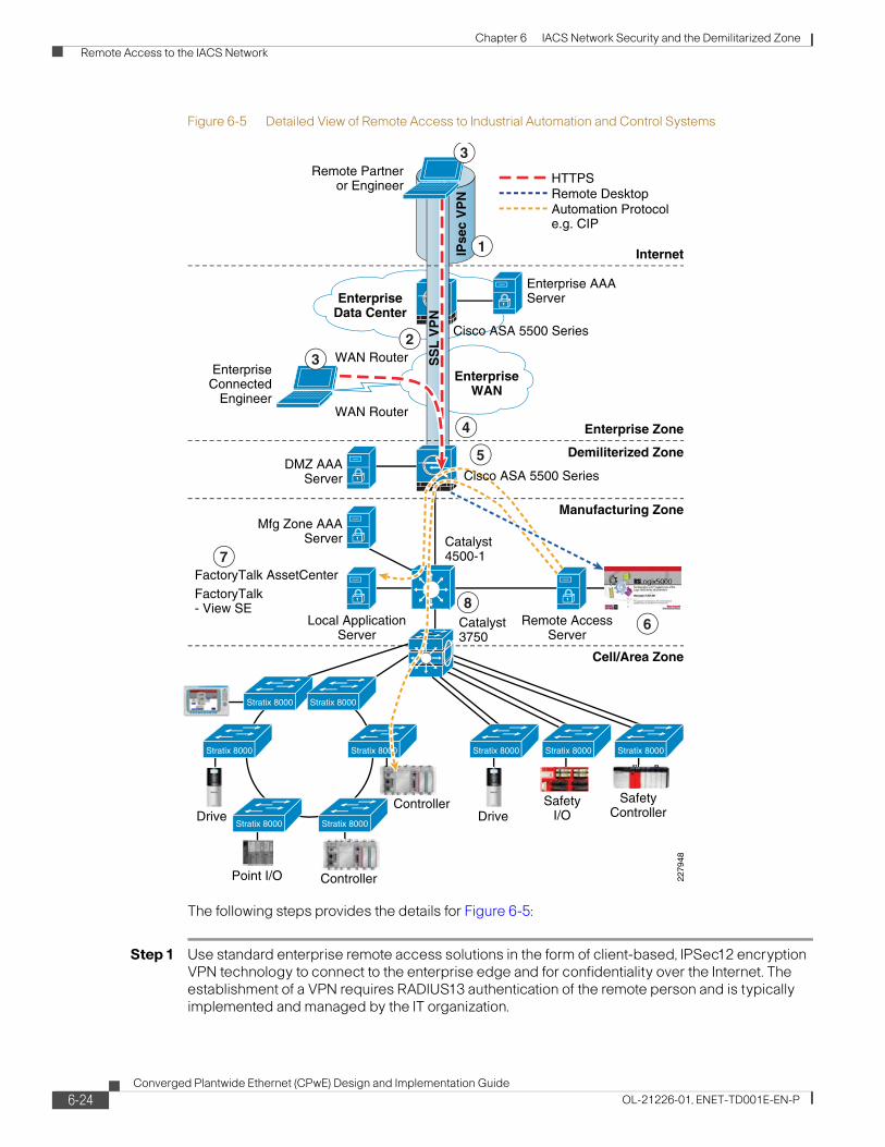
Chapter 6 IACS Network Security and the Demilitarized Zone Remote Access to the IACS Network
Figure 6-5 Detailed View of Remote Access to Industrial Automation and Control Systems
The following steps provides the details for Figure 6-5:
Step 1 Use standard enterprise remote access solutions in the form of client-based, IPSec12 encryption VPN technology to connect to the enterprise edge and for confidentiality over the Internet. The establishment of a VPN requires RADIUS13 authentication of the remote person and is typically implemented and managed by the IT organization.
EnterpriseData Center
EnterpriseWAN
Enterprise Zone
Demiliterized Zone
Cell/Area Zone
Cisco ASA 5500 Series
Catalyst4500-1
Catalyst3750
Manufacturing Zone
Internet
EnterpriseConnected
Engineer
Remote Partneror Engineer
Local ApplicationServer
WAN Router
WAN Router
ControllerPoint I/O
DriveSafety
ControllerSafety
I/OController
FactoryTalk AssetCenterFactoryTalk- View SE
IPse
c V
PN
Mfg Zone AAAServer
DMZ AAAServer
Remote AccessServer
2279
48
Enterprise AAAServer
HTTPS
Stratix 8000
Stratix 8000 Stratix 8000
Stratix 8000Stratix 8000
Stratix 8000
Drive
1
2
4
5
7
86
SS
L V
PN
3
3
Remote DesktopAutomation Protocole.g. CIP
Cisco ASA 5500 Series
Stratix 8000 Stratix 8000 Stratix 8000
6-24Converged Plantwide Ethernet (CPwE) Design and Implementation Guide
OL-21226-01, ENET-TD001E-EN-P

Chapter 6 IACS Network Security and the Demilitarized Zone Remote Access to the IACS Network
Step 2 Limit access of remote partners connecting via IPSec to DMZ/firewalls using ACLs. Connect to the DMZ through a secure browser Hypertext Transfer Protocol Secure (HTTPS) only.
Step 3 Access a secure browser (HTTPS) portal application running on the DMZ/firewalls. This requires an additional login/authentication.
Step 4 Use a Secure Socket Layer (SSL)14 VPN session between the remote client and the plant DMZ firewall and restrict application usage to a remote terminal session15 (e.g., Remote Desktop Protocol) over HTTPS.
Step 5 Use intrusion detection and prevention systems (IPSs/IDSs) on the firewall to inspect traffic to and from the remote access server for attacks and threats, and appropriately stop them. This is important to prevent viruses and other security threats from remote machines from traversing the firewall and impacting the remote access server.
Step 6 Allow the remote user to execute, via the terminal session, a selected set of industrial control applications that reside on the remote access server. Application-level login/authentication is required.
Step 7 Implement application security that restricts users from the remote access server to a limited set of application functions (such as read-only, non-line-of-site functions).
Step 8 Segment the remote access server on a separate VLAN and have all traffic between the remote access server and the Manufacturing zone go back through the firewall. Apply intrusion protection and detection services to this traffic to protect the Manufacturing zone from attacks, worms, and viruses.
Use of Standard IT-Based Remote Enterprise Access—IPSec VPN
Most enterprise security guidelines and regulations maintain that all access to corporate networks should be tightly managed. Therefore, any access to the corporate network for remote partners or employees should be granted and deployed using standard IT-based remote enterprise access solutions.
These solutions typically involve establishing an account and authorization for the end user and providing a VPN connection to the corporate network from wherever the end user has network access. VPN technologies include IPSec and Secure Sockets Layer (SSL). IPSec-based VPNs are the most widely deployed remote access technology used by most enterprises today. IPSec VPN technology does, however, require software to be loaded on the remote user’s computer. SSL-based VPNs are becoming more popular as they can be deployed in a clientless manner (the client system only requires a web browser).
The recommended architecture described in CPwE uses IPSec-based VPN for the teleworker access to the enterprise network. The installation of the software client on a remote user’s computer to support IPSec VPN can sometimes be a challenge for external users such as partners or suppliers, depending on their corporate policies and technologies utilized. At this time, however, given the wide deployment of IPSec VPN solutions for enterprise-level access and technical considerations regarding the capabilities and interaction of SSL and IPSec VPN technologies, it is recommended that IPSec VPN solutions be used for access to the enterprise-level network. Additional options to implement remote access capabilities without the use of an end-user software client may be possible as technology and market adoption evolve.
Access to enterprise networks normally requires authentication, authorization, and accounting (AAA), often established with some type of a RADIUS server. In addition, enterprise IT organizations may even have established Network Access Control (NAC) for remote users to verify that the external systems are running a certain level of code and have certain security precautions (often
6-25Converged Plantwide Ethernet (CPwE) Design and Implementation Guide
OL-21226-01, ENET-TD001E-EN-P

Chapter 6 IACS Network Security and the Demilitarized Zone Remote Access to the IACS Network
referred to as posture) in place. Although CPwE does not specifically discuss NAC, some corporate polices may require that any remote users have their posture verified through NAC. NAC brings advantages such as protecting the other infrastructure (such as a remote access server) from possibly getting infected or impacted by any existing viruses, keystroke loggers, spyware, or worms that remote users may unknowingly have on their remote systems.
The establishment of a remote account for a remote partner is usually not a temporary or instant service. It may require a certain amount of time to establish initially, so may not address situations where ad-hoc or unknown user access is required. Once established, however, it is typically readily available, supported, and in place for a specified amount of time and is therefore an appropriate solution for internal employees and key partners with known users.
Permissions Limiting Access of Remote Partners
Once access to the enterprise network has been established, remote partners should be given explicitly limited access to corporate resources. Remote employees/engineers have access as defined by their corporate account. Strict access control lists (ACLs) should be established for remote partners to limit access to the resources and applications they need via a limited set of IP addresses and transport-layer port numbers. In this case, access should be limited to the DMZ firewalls and the use of HTTPS protocols (port number 443). Remote partners should not have access to all other non-required IP addresses and port numbers to maintain corporate security.
These restrictions can be applied using ACLs in the corporate network infrastructure, such as the Internet edge firewall in Figure 6-5. These ACLs are usually managed and maintained by IT network operations or security teams.
Use Secure Web Browsers Supporting HTTPS
All interaction with data and applications for remote engineers and partners should be performed using web browsers supporting HTTPS. HTTPS supplies additional encryption and authentication and is commonly used for Internet applications.
Use of browsers suggests that client-based applications should not be used for remote access to IACS applications.
Establish SSL VPN Session to Plant DMZ Firewall
Once secure browser connectivity to the firewall is established, the firewall will establish an SSL VPN session to the remote user for an additional level of protection. The session further protects the traffic between the end client and the plant firewall. The remote user once again authenticates to verify which services/account on the remote access server is required.
Additionally, the plant firewalls ensure that all remote users are authenticated and authorized to use the remote access services.
Intrusion Protection/Detection
Once a user has established a session, the firewall’s intrusion detection and protection services come into play to inspect traffic into and out of the firewall for various types of network-born threats. IDS/IPS was specified as part of CPwE to inspect all traffic passing through the firewalls. IDS/IPS provides an additional level of security to stop threats or attacks that may originate from the remote system and prevents these threats from impacting systems in the DMZ or the Manufacturing zone by dropping malicious traffic at the source.
6-26Converged Plantwide Ethernet (CPwE) Design and Implementation Guide
OL-21226-01, ENET-TD001E-EN-P

Chapter 6 IACS Network Security and the Demilitarized Zone Remote Access to the IACS Network
Remote Terminal Session to Remote Access Server
Once secure browser connectivity has been established to the DMZ, the firewall can allow the user to access the remote access server through a terminal session. This can be established using Remote Desktop Protocol (RDP), Citrix, Virtual Network Computing (VNC), or other terminal session technologies. The firewall prompts the user to authenticate using a RADIUS server before being authorized to access the remote access server. The plant firewall (such as Cisco’s ASA 5500 Series Firewall Edition) should come with Java plug-ins that natively support terminal session technologies within the SSL VPN portal. The remote desktop session is then hosted by the firewall using SSL VPN (provided by the Java plug-in) allowing the remote user to view and operate approved applications (based on their RADIUS authorization) on a dedicated server in the Manufacturing zone.
By only allowing remote terminal protocols, the potential for viruses or attacks through the remote session is significantly reduced, and the plant can audit and record the actions taken by a remote engineer or partner.
IACS Applications on Remote Access Server
The remote access server hosts the approved IACS applications, such as FactoryTalk® View or RSLogix™ 5000. By executing applications on a secure, dedicated server, the plant floor personnel can strictly enforce change management, version control and regulatory compliance of the applications, limit the actions that can be performed —for example by allowing read-only actions —and even limit the types of devices that can be accessed, only allowing vendors to see their relevant devices, for example.
The remote access server setup and configuration should also be carefully considered. Users authenticating to the remote access server should not be able to change their rights on either an application level or system level. For example, you do not want users of the application server editing the registry or making themselves local windows administrators. Cisco and Rockwell Automation recommend following the guidelines in the Securing Manufacturing Computing and Controller Assets at the link below. These guidelines recommend that endpoint security such as antivirus and/or Cisco Security Agent be applied to the remote access server. For more information, refer to the following URL:
http://literature.rockwellautomation.com/idc/groups/literature/documents/wp/enet-wp005_-en-e.pdf
Segment and Inspect Traffic to and from the Remote Access Server
In order to strictly control the traffic to and from the remote access server, the server should be segmented onto a specific VLAN, while traffic is inspected by the firewall. The firewall can route traffic to and from the remote access VLAN. If more than one remote access server is available, each server can be on a different VLAN and each VLAN can have access to a specific set of other IACS VLANs, thereby further limiting a remote user’s view of the Manufacturing zone.
Organizational ConsiderationsAs with any IACS networking solution, successful implementation of remote access capabilities typically require a combination of IT and plant floor resources. It is important that both organizations agree on the architecture and split the responsibilities throughout the lifecycle (design, implementation, management, etc.) based on each group’s skills, capabilities, and resources.
6-27Converged Plantwide Ethernet (CPwE) Design and Implementation Guide
OL-21226-01, ENET-TD001E-EN-P
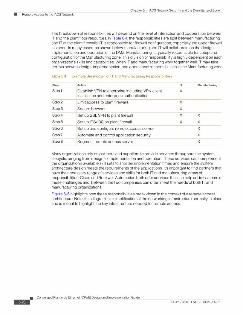
Chapter 6 IACS Network Security and the Demilitarized Zone Remote Access to the IACS Network
The breakdown of responsibilities will depend on the level of interaction and cooperation between IT and the plant floor resources. In Table 6-1, the responsibilities are split between manufacturing and IT at the plant firewalls; IT is responsible for firewall configuration, especially the upper firewall instance. In many cases, as shown below, manufacturing and IT will collaborate on the design, implementation and operation of the DMZ. Manufacturing is typically responsible for setup and configuration of the Manufacturing zone. This division of responsibility is highly dependent on each organization's skills and capabilities. When IT and manufacturing work together well, IT may take certain network design, implementation, and operational responsibilities in the Manufacturing zone.
Many organizations rely on partners and suppliers to provide services throughout the system lifecycle, ranging from design to implementation and operation. These services can complement the organization's available skill sets to shorten implementation times and ensure the system architecture design meets the requirements of the applications. It's important to find partners that have the necessary range of services and skills for both IT and manufacturing areas of responsibilities. Cisco and Rockwell Automation both offer services that can help address some of these challenges and, between the two companies, can often meet the needs of both IT and manufacturing organizations.
Figure 6-6 highlights how these responsibilities break down in the context of a remote access architecture. Note, this diagram is a simplification of the networking infrastructure normally in place and is meant to highlight the key infrastructure needed for remote access.
Table 6-1 Example Breakdown of IT and Manufacturing Responsibilities
Step Action IT Manufacturing
Step1 Establish VPN to enterprise including VPN client installation and enterprise authentication
X
Step 2 Limit access to plant firewalls X
Step 3 Secure browser X
Step 4 Set up SSL VPN to plant firewall X X
Step 5 Set up IPS/IDS on plant firewall X X
Step 6 Set up and configure remote access server X
Step 7 Automate and control application security X
Step 8 Segment remote access server X
6-28Converged Plantwide Ethernet (CPwE) Design and Implementation Guide
OL-21226-01, ENET-TD001E-EN-P

Chapter 6 IACS Network Security and the Demilitarized Zone Remote Access to the IACS Network
Figure 6-6 Example IT and Manufacturing Areas of Responsibility
Catalyst4500-1
Local ApplicationServer
Remote AccessServer
EnterpriseData Center
EnterpriseWAN
Enterprise Zone
Demiliterized Zone
Cell/Area Zone
Cisco ASA 5500 Series
Cisco ASA 5500 Series
Manufacturing Zone
Internet
ITResponsibility
EnterpriseConnected
Engineer
Remote Partneror Engineer
Controller
FactoryTalk AssetCenterFactoryTalk- View SE
IPse
c V
PN
2279
49
ProductionControlResponsibility
SS
L V
PN
6-29Converged Plantwide Ethernet (CPwE) Design and Implementation Guide
OL-21226-01, ENET-TD001E-EN-P

Chapter 6 IACS Network Security and the Demilitarized Zone Remote Access to the IACS Network
6-30Converged Plantwide Ethernet (CPwE) Design and Implementation Guide
OL-21226-01, ENET-TD001E-EN-P

Converged Plantwide Ethernet (CPwOL-21226-01, ENET-TD001E-EN-P
C H A P T E R 7
Testing the CPwE SolutionOverviewThis chapter describes the test plans and environment used to validate the key concepts outlined in this solution. This chapter covers the following:
• Key test objectives, activities and exit criteria to validate the solution
• Describe the test environments in which the tests will be conducted
• Summarize the test execution steps including test scenarios and test cases
For detailed test results refer to Appendix C, “Complete Test Data” and refer to Appendix B, “Test Result Analysis” for analysis of those results. The intention of providing this level of detail is to allow implementers of IACS networks to estimate the various characteristics of their own networks (e.g., network convergence) and to compare their own test results to determine whether improvements are possible following the guidelines outlined in this Design and Implementation Guide.
Introduction
Test ObjectiveThe objective of the test was to provide input and background for the requirements and solution architecture. The test approach is designed to enable Cisco and Rockwell Automation to provide detailed design and implementation guidance for applying industrial Ethernet to production facilities. The test was also designed to produce results that customers and implementers of IACS networks can use to plan and design their own networks. This test plan is designed to test key network characteristics to best support automation and control system. The key plant network design requirements and considerations to be tested include the following:
• Performance/real-time communications (network latency and jitter)
• Availability (e.g., resiliency protocols)
• Adaptability (e.g., topology)
• Security (e.g., remote access)
• Scalability
7-1E) Design and Implementation Guide
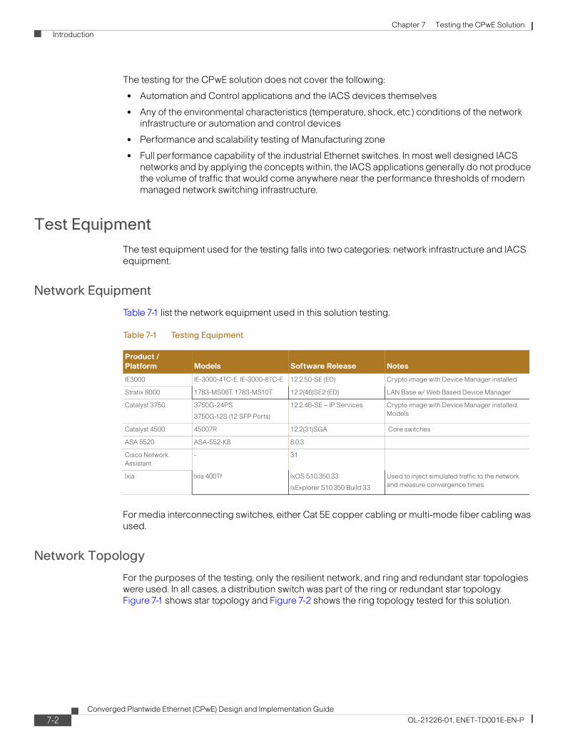
Chapter 7 Testing the CPwE Solution Introduction
The testing for the CPwE solution does not cover the following:
• Automation and Control applications and the IACS devices themselves
• Any of the environmental characteristics (temperature, shock, etc.) conditions of the network infrastructure or automation and control devices
• Performance and scalability testing of Manufacturing zone
• Full performance capability of the industrial Ethernet switches. In most well designed IACS networks and by applying the concepts within, the IACS applications generally do not produce the volume of traffic that would come anywhere near the performance thresholds of modern managed network switching infrastructure.
Test EquipmentThe test equipment used for the testing falls into two categories: network infrastructure and IACS equipment.
Network Equipment
Table 7-1 list the network equipment used in this solution testing.
For media interconnecting switches, either Cat 5E copper cabling or multi-mode fiber cabling was used.
Network Topology
For the purposes of the testing, only the resilient network, and ring and redundant star topologies were used. In all cases, a distribution switch was part of the ring or redundant star topology. Figure 7-1 shows star topology and Figure 7-2 shows the ring topology tested for this solution.
Table 7-1 Testing Equipment
Product / Platform Models Software Release Notes
IE3000 IE-3000-4TC-E, IE-3000-8TC-E 12.2.50-SE (ED) Crypto image with Device Manager installed
Stratix 8000 1783-MS06T, 1783-MS10T 12.2(46)SE2 (ED) LAN Base w/ Web Based Device Manager
Catalyst 3750 3750G-24PS
3750G-12S (12 SFP Ports)
12.2.46-SE – IP Services Crypto image with Device Manager installed. Models
Catalyst 4500 45007R 12.2(31)SGA Core switches
ASA 5520 ASA-552-K8 8.0.3
Cisco Network Assistant
- 3.1
Ixia Ixia 400Tf IxOS 5.10.350.33
IxExplorer 5.10.350 Build 33
Used to inject simulated traffic to the network and measure convergence times.
7-2Converged Plantwide Ethernet (CPwE) Design and Implementation Guide
OL-21226-01, ENET-TD001E-EN-P
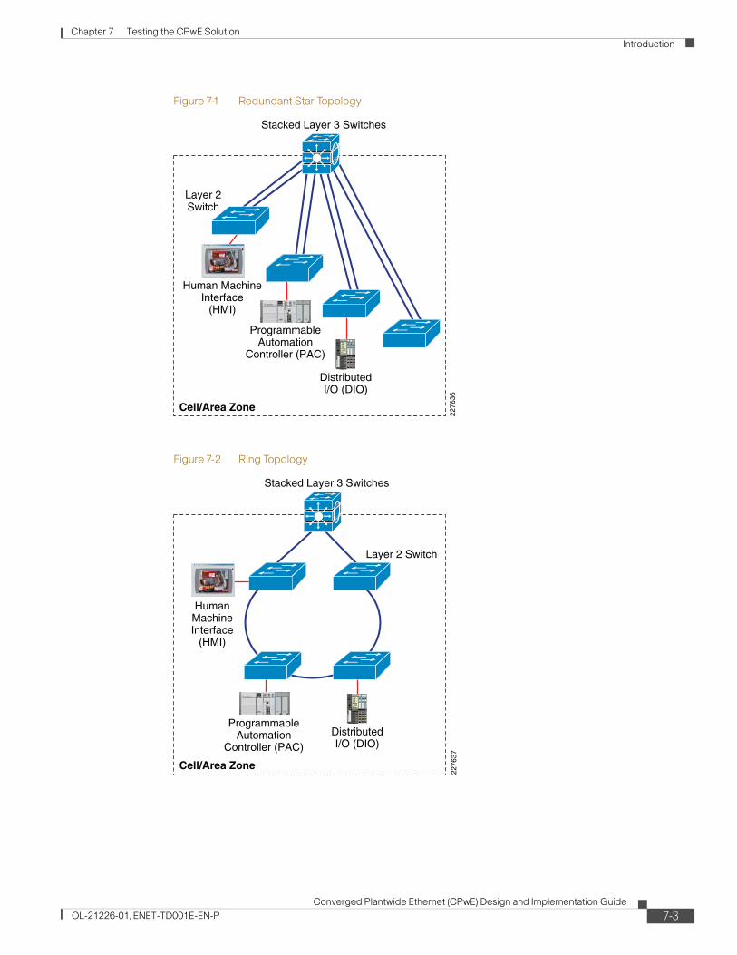
Chapter 7 Testing the CPwE Solution Introduction
Figure 7-1 Redundant Star Topology
Figure 7-2 Ring Topology
Layer 2Switch
2276
36
Cell/Area Zone
Stacked Layer 3 Switches
ProgrammableAutomation
Controller (PAC)
DistributedI/O (DIO)
Human MachineInterface
(HMI)
2276
37
Cell/Area Zone
Stacked Layer 3 Switches
Layer 2 Switch
ProgrammableAutomation
Controller (PAC)
HumanMachineInterface
(HMI)
DistributedI/O (DIO)
7-3Converged Plantwide Ethernet (CPwE) Design and Implementation Guide
OL-21226-01, ENET-TD001E-EN-P

Chapter 7 Testing the CPwE Solution Introduction
IACS Equipment
Table 7-2 IACS Equipment
Quantity Catalog # Description
L61 #3, CLGX_A, CLGX_B
1 1756-A7 1756 Chassis 7 slots
2 1756-EN2T EtherNet 10-100M Bridge Module
2 1756-L64 Logix5564 Processor With 16 Mbytes Memory (PAC)
1 1756-PA75 85-265V AC Power Supply (5V @ 13 Amp)
L61 #3, CLGX_C, CLGX_D
1 1756-A7 1756 Chassis 7 slots
2 1756-EN2T EtherNet 10-100M Bridge Module
2 1756-L64 Logix5564 Processor With 16 Mbytes Memory (PAC)
1 1756-PA75 85-265V AC Power Supply (5V @ 13 Amp)
L61 #2, CLGX_E, CLGX_F
1 1756-A10 1756 Chassis 10 slots
2 1756-EN2T EtherNet 10-100M Bridge Module
1 1756-IB16ISOE 10-30 VDC Isolated Sequence of Event Input 16 Pts (36 Pin)
2 1756-L61 Logix5561 Processor With 2Mbytes Memory (PAC)
1 1756-OB16D 19-30 VDC Diagnostic Output 16 Pts (36 Pin)
1 1756-PA75 85-265V AC Power Supply (5V @ 13 Amp)
2 1756-TBCH 36 Pin Screw Clamp Block With Standard Housing
L61 #1, CLGX_G, CLGX_H
1 1756-A10 1756 Chassis 10 slots
2 1756-EN2T EtherNet 10-100M Bridge Module
1 1756-ENBT EtherNet 10-100M Bridge Module
1 1756-IB16 10-31 VDC Input 16 Pts (20 Pin)
2 1756-L61 Logix5561 Processor With 2Mbytes Memory (PAC)
1 1756-OB16E 10-31 VDC Elec Fused Output 16 Pts (20 Pin)
1 1756-PA75 85-265V AC Power Supply (5V @ 13 Amp)
2 1756-TBNH 20 Position NemA Screw Clamp Block
L43 #1 CPX_I
2 1768-ENBT CompactLogix L4X Ethernet/IP Bridge Module
1 1768-L43 CompactLogix L45Processor, 3.0M Memory (PAC)
1 1768-PA3 CompactLogix 5V/24V ac Input Non-Redundant Power Supply for CompactLogix Systems
1 1769-ECR Right End Cap Terminator
L32E #2 CPX_J
1 1769-ECR Right End Cap Terminator
7-4Converged Plantwide Ethernet (CPwE) Design and Implementation Guide
OL-21226-01, ENET-TD001E-EN-P

Chapter 7 Testing the CPwE Solution Introduction
2 1769-IQ6XOW4 Combo 6pt 24 VDC Input, 4pt AC/DC Relay Output
1 1769-L32E CompactLogix EtherNet Processor, 750k Memory (PAC)
1 1769-PA2 120/240V AC Power Supply (5V @ 2 Amp)
L43 #2 CPX_L
2 1768-ENBT CompactLogix L4X Ethernet/IP Bridge Module
1 1768-L43 CompactLogix L45Processor, 3.0M Memory (PAC)
1 1768-PA3 CompactLogix 5V/24V ac Input Non-Redundant Power Supply for CompactLogix Systems
1 1769-ECR Right End Cap Terminator
L32E #1 CPX_M1 1769-ECR Right End Cap Terminator
2 1769-IQ6XOW4 Combo 6pt 24 VDC Input, 4pt AC/DC Relay Output
1 1769-L32E CompactLogix EtherNet Processor, 750k Memory (PAC)
1 1769-PA2 120/240V AC Power Supply (5V @ 2 Amp)
LS61S #1 CLGX_O
1 1756-A7 1756 Chassis 7 slots
2 1756-EN2T EtherNet 10-100M Bridge Module
1 1756-L61S Logix5561 Safety Processor With 2 Mbytes Memory (PAC)
1 1756-LSP Safety Partner Coprocessor
1 1756-PA75 85-265V AC Power Supply (5V @ 13 Amp)
LS61S #2 CLGX_P
1 1756-A7 1756 Chassis 7 slots
2 1756-EN2T EtherNet 10-100M Bridge Module
1 1756-L61S Logix5561 Safety Processor With 2 Mbytes Memory (PAC)
1 1756-LSP Safety Partner Coprocessor
1 1756-PA75 85-265V AC Power Supply (5V @ 13 Amp)
FlexIO #100
1 1794-AENT Ethernet Adapter Module (Distributed I/O)
1 1794-IB8 24V DC Sink Input Module, 8 Point
1 1794-OB16 24V DC Source Output Module, 16 Point
1 1794-PS13 85-264 VAC To 24 VDC 1.3A Power Supply
2 1794-TB3 Terminal Base, 3-Wire
FlexIO 102
1 1794-AENT Ethernet Adapter Module (Distributed I/O)
1 1794-IB8 24V DC Sink Input Module, 8 Point
1 1794-OB16 24V DC Source Output Module, 16 Point
1 1794-PS13 85-264 VAC To 24 VDC 1.3A Power Supply
2 1794-TB3 Terminal Base, 3-Wire
Table 7-2 IACS Equipment (continued)
Quantity Catalog # Description
7-5Converged Plantwide Ethernet (CPwE) Design and Implementation Guide
OL-21226-01, ENET-TD001E-EN-P

Chapter 7 Testing the CPwE Solution Introduction
Test ApproachTo supply the feedback as required by the testing objectives, Cisco and Rockwell Automation designed the following two key tests to be executed:
• Network resiliency tests on a variety of test configurations measuring both application sensitivity to outages and network convergence (defined in the “Test Measurements” section on page 7-19)
• Screw-to-screw tests to measure latency as seen by the IACS application and the impact of network scalability on latency
This section describes each of the above tests in more detail, including the key objectives of each test.
Cisco and Rockwell Automation carried out these tests in each of their labs. For Cisco, the tests were conducted at the San Jose campus location. For Rockwell Automation, the tests were conducted at the Mayfield Heights location. The test environments of each lab were as similar as possible, where both labs were operating with the same level of IACS software, nearly identical IACS equipment, and nearly identical network configurations. The most significant difference was that the Rockwell Automation lab tested with Stratix 8000 IE switches and the Cisco lab tested with IE 3000 switches. As a result, there are some minor differences in the configurations, as noted in Chapter 4, “CPwE Solution Design—Manufacturing and Demilitarized Zones.” The test results were very similar and have been integrated into this chapter.
PointIO 103
1 1734-AENT 1734 EtherNet/IP Adapter (Distributed I/O)
1 1734-IB2 10-28 VDC 2 Points Sink Input Module
1 1734-IR2 2 Points RTD Input Module
1 1734-OW4 4 Points Relay Output Module
2 1734-TB Two-Piece Terminal Base, 8-point, Screw Clamp Terminals
1 1734-TB3 Two-Piece Terminal Base, 12-point, Screw Clamp Terminals
1 1794-PS13 85-264 VAC To 24 VDC 1.3A Power Supply
Point IO 104
1 1734-AENT 1734 EtherNet/IP Adapter (Distributed I/O)
1 1734-IB2 10-28 VDC 2 Points Sink Input Module
1 1734-IR2 2 Points RTD Input Module
2 1734-TB Two-Piece Terminal Base, 8-point, Screw Clamp Terminals
1 1794-PS13 85-264 VAC To 24 VDC 1.3A Power Supply
Safety IO 107 & 108
2 1791ES-IB8XOBV4 24 VDC 8 Sink Input and 4 Output Module on EtherNet/IP (Distributed I/O)
PView+ #1 (HMI)
1 2711P-T7C4D2 PanelView Plus 700, 6.5'' TFT Display, Touch, Standard Communications (EtherNet & RS-232), DC Input, 128MB Flash/128MB RAM
Table 7-2 IACS Equipment (continued)
Quantity Catalog # Description
7-6Converged Plantwide Ethernet (CPwE) Design and Implementation Guide
OL-21226-01, ENET-TD001E-EN-P

Chapter 7 Testing the CPwE Solution Introduction
In addition, Cisco and Rockwell Automation collaborated to establish secure remote access for the Rockwell Automation team to access Cisco's San Jose IACS lab. Rockwell Automation was able to securely access IACS applications in Cisco's IACS lab and assist with deployment and maintenance of the IACS equipment in Cisco's lab during the test phase. No particular test cases were developed, but the relevant configurations are supplied here and the design and implementation recommendations in this guide are based on the successful deployment of that feature. Note that Cisco and Rockwell Automation have not and will not produce detailed configurations of the IT portion of the secure remote access as that was deployed on operative Cisco production equipment.
Network Resiliency
The test was designed to measure the network convergence under a number of fault and recovery situations in a variety of network configurations. Network convergence is defined as the time it takes the network to identify a failure (or restore) situation, make appropriate changes in switching functions, and reestablish interconnectivity. This test was designed to provide input and verify recommendations in regards to the following:
• Media, in particular the use of fiber versus copper for inter-switch uplinks
• Network topology (ring versus redundant star)
• Network scalability in terms of the number of switches and number of end-devices, in particular the impact of a larger network on network convergence.
• Network resiliency protocol, in particular between Spanning Tree versions, EtherChannel, and Flex Links.
• Network behavior in a variety of failure/restore scenarios, so customers and implementers can make decisions about how to react and potentially when to restore failed links or devices.
This section covers the following:
• A description of the IACS application that was in operation during the testing
• The key measurements collected during the testing, including application sensitivity and network convergence
• A description of the test organization including test variables, test suites developed and test cases executed
IACS Application
The IACS application employs the following:
• 14 controllers, each with a dedicated network card
• 6 I/O modules
• 1 PanelView Plus HMI
Each network module was configured for approximately 80 percent utilization. Table 7-3 lists the packets per-second approximate loading for the types of network modules in the test environment.
Table 7-3 Packets Per-Second Loading
Catalog # Max Class 1 PPS Approximate Tested PPS loading
1756-EN2T 10000 8000
1768-ENBT 5000 4000
1769-L35E 4000 3200
7-7Converged Plantwide Ethernet (CPwE) Design and Implementation Guide
OL-21226-01, ENET-TD001E-EN-P

Chapter 7 Testing the CPwE Solution Introduction
Table 7-4 lists all the controllers, their communication modules, and the relevant network and IACS application data.
The following controllers have the specified tasks:
• CLGX_E—Monitors the status of its I/O LED and the I/O LEDs of the other controllers. This is handled with GSV instructions locally and with a consumed tag within CLGX_E from each of the other controllers with the exception of CLGX_F.
• CLGX_F has the screw-to-screw test logic. CLGX_F is not involved in the network resiliency tests.
Figure 7-3 depicts the IACS devices and the network infrastructure for the Cell/Area zone in a ring topology that was used for testing network resiliency, application latency, and jitter.
Table 7-4 Controllers
Device Name Type
EIP Network Interface IP Address Connected to Owns Produces* Consumers
CLGX A 1756-L64 EN2T 10.17.x.50 IES-6 Tags for CLGX_B Tags from CLGX_H
CLGX B 1756-L64 EN2T 10.17.x.51 IES-5 Tags for CLGX_G Tags from CLGX_A
CLGX C 1756-L64 EN2T 10.17.x.52 IES-4 Flex 102 Tags for CLGX_G Flex 102:1794-IB16 & 1794-OB16
Tags from CLGX_P
CLGX D 1756-L64 EN2T 10.17.x.54 IES-3 Point 103 Tags for CLGX_O Point 103: 1734-IR2, 1734-IB2, and 1734-OW4
Tags from CLGX_C
CLGX E 1756-L61 EN2T 10.17.x.56 IES-7 Point 104 Tags from all controllers, except F
Listen Flex100 1794-IB16 module
Point 104: 1734-IR2, 1734-IB2, and 1734-OW4
CLGX F 1756-L61 EN2T 10.17.x.57 IES-8 Flex 100 Flex 100: 1794-AENT, 1794-IB16, & 1794-OB16
CLGX G 1756-L61 EN2T 10.17.x.58 IES-2 Tags for CLGX_H Tags from CLGX_B
CLGX H 1756-L61 EN2T 10.17.x.60 IES-1 Tags for CLGX_A Tags from CLGX_G
CPX I 1768-L43 1768-ENBT 10.17.x.62 IES-7 Tag for CPX_L Tags from CPX_L
CPX J 1769-L32E Included 10.17.x.64 IES-5 Tags for CPX_M
CPX L 1768-L43 1768-ENBT 10.17.x.66 IES-6 Tags for CPX_I Tags from CPX_L
CPX M 1769-L32E Included 10.17.x.68 IES-4 Tags from CPX_J
CLGX O 1756-L61S EN2T 10.17.x.70 IES-1 Safety 107 Tags for GuardLogix_P
Tags from CLGX_D
Safety 107: 2 connections
CLGX P 1756-L61S EN2T 10.17.x.72 IES-8 Safety 108 Tags to CLGX_C Tags from GuardLogix_O
Safety 108: 2 connections
Flex 100 1794-AENT Included 10.17.x.100 IES-7 Tags for CLGX_F, CLGX_E (listen)
Flex 102 1794-AENT Included 10.17.x.102 IES-3 Tags for CLGX_C
Point 103 1734-AENT Included 10.17.x.103 IES-4 Tags for CLGX_D
Point 104 1734-AENT Included 10.17.x.104 IES-8 Tags for CLGX_E
Safety 107 1791-IB8XOBV4 Included 10.17.x.107 IES-2 Tags for CLGX_O
Safety 108 1791-IB8XOBV4 Included 10.17.x.108 IES-3 Tags for CLGX_P
PV 150 PV+ 700 Included 10.17.x.150 IES-5
7-8Converged Plantwide Ethernet (CPwE) Design and Implementation Guide
OL-21226-01, ENET-TD001E-EN-P

Chapter 7 Testing the CPwE Solution Introduction
Figure 7-3 IACS Devices and Network Infrastructure for Cell/Area Zone in Ring Topology
Test Measurements
This section describes the key measurements collected during the testing for CPwE, including network convergence and application sensitivity during network convergence.
Network Convergence
Network convergence is measured in the same manner as in Phase 1. The network traffic generator (see the “Test Equipment” section on page 7-2) generates bidirectional UDP unicast or multicast packet streams from two ports on the network topology. Each port both send packets to and capture packets from the other port. Two such streams are used to measure network convergence from different points in the topology. The test streams were ran for a set period of time, during which a topology change was executed (e.g., pull an uplink cable or port shutdown). Each port measure the number of packets received from the sending port. The convergence time is measured using the following formula:
Convergence in milliseconds = [(Tx - Rx) / packet rate] * 1000 ms/s
VLAN xx10.17.xx.0/24
RA Devices10.17.xx.50 -150
Flex 100Flex 102
Point 10310.17.xx.103, FA1/3
PV15010.17.xx.150, FA1/3
CPX_L10.17.xx.66, FA1/2
CPX_A10.17.xx.50
CPX_B10.17.xx.51
CLGX_P
CPX_I
CLGX_C10.17.xx.52, FA1/1
CPX_M
CPX_J
Saftey 107
10.17.xx.13 10.17.xx.14
10.17.xx.12
10.17.xx.11
10.17.xx.10
10.17.xx.15
10.17.xx.16
FA1/1
FA1/1
FA1/2
CLGX_D10.17.xx.54, FA1/3
10.17.xx.57, FA1/1
10.17.xx.56, FA1/1
CLGX_ECLGX_F
CLGX_GCLGX_H
10.17.xx.58,FA1/2
10.17.xx.60,FA1/2
10.17.xx.62, FA1/2
1.17.xx.64, FA1/20
10.17.xx.68,FA1/2
CLGX_O
10.17.xx.70, FA1/3 10.17.xx.72, FA1/3
10.17.xx.100, FA1/310.17.xx.102, FA1/2
10.17.xx.104,FA1/2
10.17.xx.107, FA1/1
Saftey 10810.17.xx.108, FA1/1
Point 104
G1/1
G1/0//25 G2/0/25
G1/1
G1/1
G1/1
G1/1G1/1
G1/1
G1/1
G1/2
G1/2
G1/2
G1/2
G1/2
G1/2
G1/2
IES-1
IES-7IES-2
IES-8
CZ-3750
IES-4 IES-5
IES-6
10.17.xx.17
IES-3
2279
71
7-9Converged Plantwide Ethernet (CPwE) Design and Implementation Guide
OL-21226-01, ENET-TD001E-EN-P
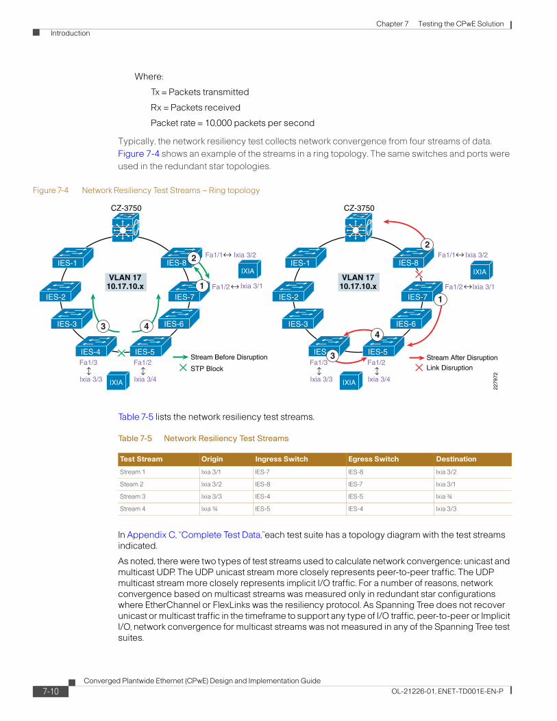
Chapter 7 Testing the CPwE Solution Introduction
Where:
Tx = Packets transmitted
Rx = Packets received
Packet rate = 10,000 packets per second
Typically, the network resiliency test collects network convergence from four streams of data. Figure 7-4 shows an example of the streams in a ring topology. The same switches and ports were used in the redundant star topologies.
Figure 7-4 Network Resiliency Test Streams – Ring topology
Table 7-5 lists the network resiliency test streams.
In Appendix C, “Complete Test Data,”each test suite has a topology diagram with the test streams indicated.
As noted, there were two types of test streams used to calculate network convergence: unicast and multicast UDP. The UDP unicast stream more closely represents peer-to-peer traffic. The UDP multicast stream more closely represents implicit I/O traffic. For a number of reasons, network convergence based on multicast streams was measured only in redundant star configurations where EtherChannel or FlexLinks was the resiliency protocol. As Spanning Tree does not recover unicast or multicast traffic in the timeframe to support any type of I/O traffic, peer-to-peer or Implicit I/O, network convergence for multicast streams was not measured in any of the Spanning Tree test suites.
VLAN 1710.17.10.x
Link Disruption
Stream After Disruption
Fa1/1 Ixia 3/2
Fa1/2
Fa1/3
Ixia 3/1
Ixia 3/3
Fa1/2
Ixia 3/4
IXIA
IXIA
IES-1
IES-7IES-2
IES-8
CZ-3750
IES-3
IES-4 IES-5
IES-6
VLAN 1710.17.10.x
STP Block
Stream Before Disruption
Fa1/1 Ixia 3/2
Fa1/2
Fa1/3
Ixia 3/1
Ixia 3/3
Fa1/2
Ixia 3/4
IXIA
IXIA
IES-1
IES-7IES-2
IES-8
CZ-3750
IES-3
IES-4 IES-5
IES-6
2279
72
2
2
1
1
44
3
3
Table 7-5 Network Resiliency Test Streams
Test Stream Origin Ingress Switch Egress Switch Destination
Stream 1 Ixia 3/1 IES-7 IES-8 Ixia 3/2
Steam 2 Ixia 3/2 IES-8 IES-7 Ixia 3/1
Stream 3 Ixia 3/3 IES-4 IES-5 Ixia ¾
Stream 4 Ixia ¾ IES-5 IES-4 Ixia 3/3
7-10Converged Plantwide Ethernet (CPwE) Design and Implementation Guide
OL-21226-01, ENET-TD001E-EN-P

Chapter 7 Testing the CPwE Solution Introduction
Application Sensitivity
The tests are designed to measure three types of application flows. These flows are commonly designed into automation and control systems. These flows are used to measure the impact network disruption and resulting network convergence has on the application traffic flow.
• HMI (explicit)—Where communication is established between controllers and HMI devices. The flow is designed to not disrupt in network disruptions of under 20 seconds. This is an example of information/process traffic as described in the “Real-Time Communication, Determinism, and Performance” section on page 3-5.
• Peer-to-peer (implicit unicast) represents communication between controllers that is typically passed via UDP unicast packets. This flow was designed to not disrupt in network disruptions of under 100 ms. This is an example of time critical traffic as described in the “Real-Time Communication, Determinism, and Performance” section on page 3-5.
• Implicit I/O (implicit multicast) represents communication between controllers and I/O devices and drives that is typically passed via UDP multicast packets. This flow was designed to not disrupt in network disruptions of under 100 ms. This is an example of time critical traffic as described in the “Real-Time Communication, Determinism, and Performance” section on page 3-5.
These traffic flows represent the type of IACS data and network traffic that is handled by the network infrastructure. If any of the operational devices were to have a communication fault, the IACS application would display the controller and flag at fault. Traffic types 2 and 3 are relatively similar in that they both timeout at around 100 ms and are both based upon UDP traffic. The difference between them was whether unicast or multicast communication modes were used to communicate the data. In all network resiliency test cases, the IACS application was operational and communicating data. Therefore, the base test case has the following:
• 21 IACS devices on the network
• Producing 80 streams of data (90 multicast groups)
In the current IACS application, only one of the implicit traffic types, peer-to-peer or Implicit I/O traffic flows are operational during a test run. Cisco and Rockwell Automation choose to operate the Implicit I/O traffic flow for the redundant star topologies.
The tests were designed to measure whether or not the application times out when a network fault or restoration is introduced, indicating whether the network converged fast enough to have the application avoid faulting. These test results are included in the appendices.
Test Organization
This section describes the organization of the network resiliency testing. First, there is a description of the test variables. This is a summary of the key variables that the network resiliency tests took into consideration. Second, there is a description of the test suites. A test suite in this case is a network topology and configuration. For each test suite, a variety of test cases were executed. For each test case, a number of test runs were executed for a variety of inserted MAC addresses to simulate additional end-devices. Each test run was executed with the IACS application in operation and measuring whether any controller lost a connection during the test run.
Test Variables
Table 7-6 outlines the key test variables incorporated into the CPwE testing.
7-11Converged Plantwide Ethernet (CPwE) Design and Implementation Guide
OL-21226-01, ENET-TD001E-EN-P

Chapter 7 Testing the CPwE Solution Introduction
Test Suites
The test suite represents a network topology, resiliency protocol, and uplink media-type. Table 7-7 lists the test suites performed.
Note the naming convention:
• First letter is for topology where R is for ring and S for redundant star.
• Second letter is for resiliency protocol where M is for MSTP, P is for RPVST+, E is for EtherChannel, and F is for Flex Links.
• Third letter is for uplink media type where C is for Cat 5E copper (Cat 5E or 6) cabling and F is for fiber.
• The last number is for the number of switches in the topology, 8 or 16.
Table 7-6 CPwE Network Resiliency Test Variables
Variable EttF Phase 1 CPwE (Phase 2)
# of Options Options #Options Options
Resiliency protocols 1 Rapid PVST+ 2 MSTP, Rapid PVST+
Switch Composition 1 2955 2 IE 3000 & Stratix 8000
Size of the ring 2 8, 16 2 8, 16
# of Mac addresses 3 Base, 200, 400 3 Base, 200, 400
# of Network Events 8 4 failures and 4 restores 8 4 failures and 4 restores
Physical Layer 1 Copper 2 Copper and Fiber uplinks
Application Traffic type 0 Application data not collected 2 sets HMI & Peer-to-peer
HMI & Implicit I/O
Test Runs 3 3 runs were measured per test case
5 or 10 Convergence tests were run 10 times for 8-Ring tests and 5 times for 16-ring tests
Network Convergence measurement type
1 UDP Unicast 2 UDP unicast and multicast
Table 7-7 CPwE Network Resiliency Test Suites
Test Suite Topology Resiliency Protocol Uplink Physical layer # of IE switchesNetwork Convergence measurement
RMC8 Ring MSTP Copper 8 UDP Unicast
RMC16 Ring MSTP Copper 16 UDP Unicast
RPC8 Ring Rapid-PVST+ Copper 8 UDP Unicast
RMF8 Ring MSTP Fiber 8 UDP Unicast
SMC8 Redundant Star MSTP Copper 8 UDP Unicast
SMF8 Redundant Star MSTP Fiber 8 UDP Unicast
SEC8 Redundant Star EtherChannel Copper 8 UDP Unicast & multicast
SEF8 Redundant Star EtherChannel Fiber 8 UDP Unicast & multicast
SFC8 Redundant Star Flex Links Copper 8 UDP Unicast & multicast
SFF8 Redundant Star Flex Links Fiber 8 UDP Unicast & multicast
7-12Converged Plantwide Ethernet (CPwE) Design and Implementation Guide
OL-21226-01, ENET-TD001E-EN-P

Chapter 7 Testing the CPwE Solution Introduction
Test Cases
For each test suite, a variety of test cases were executed. A test case represents a type of network event, either a disruption or restoration. Table 7-8 describes the test cases executed. For each test case, a number of test runs were performed with varying amounts of simulated end-devices coming from the network generator. The eight cases of network disruption shown in Table 7-8 are performed.
Note The root bridge up/down test cases were only executed in the ring topology test suites. In a redundant star, the root bridge down represents a catastrophic failure where the network is no longer viable.
In nearly all cases, some network disruption is expected. The exception was with Flex Links that places a restored connection into standby mode, which has no noticeable impact on the traffic flows.
Table 7-8 Test Cases
Test Case Action Network Response
Bring specified link down (software) Virtually shut down the port by executing the “shut” command in CLI
Resiliency protocol perform a topology change and divert traffic over functional path
Bring specified link up (software) Virtually restore the port by executing the “no shut” command in CLI
Recognize restored connection and depending on the protocol, execute a topology change and divert traffic over new functional path (Spanning Tree and EtherChannel only)
Disconnect specified Cable (physical) Physically disconnect the cable Resiliency protocol perform a topology change and divert traffic over functional path
Reconnect specified Cable (physical) Physically restore the connection Recognize restored connection and depending on the protocol, potentially execute a topology change and divert traffic over new functional path (Spanning Tree and EtherChannel)
Root bridge down (physical) Virtually shut both Cell/Area ports on the distribution switch
Only performed for Ring/Spanning Tree test suites. Resiliency protocol performs a topology change and diverts traffic over functional path. New IGMP querier and root bride must be elected.
Root bridge up (physical) Virtually restore both Cell/Area ports on the distribution switch
Only performed for Ring/Spanning Tree test suites. Recognize restored connections and execute a topology change and divert traffic over new functional path. Revert IGMP querier and root bridge functions to distribution switch
Stack Master down Reload (reboot) the switch master in the stack Resiliency protocol performs a topology change and diverts traffic over functional path. Stack Master, root bridge, and IGMP querier functions taken over by surviving switch.
Return Switch to Stack With manual boot enabled, reboot the reloaded switch.
Except for Flex Links, resiliency protocol performs a topology change and diverts traffic over functional path. Stack Master, root bridge, and IGMP querier functions remain.
7-13Converged Plantwide Ethernet (CPwE) Design and Implementation Guide
OL-21226-01, ENET-TD001E-EN-P

Chapter 7 Testing the CPwE Solution Introduction
Summary
Table 7-9 lists all the test suites and test cases that were executed for the network resiliency portion of the CPwE test.
Not all test cases were executed for each topology for the following reasons:
• Root bridge up/down test cases were only executed in ring topology test suites. In a redundant star, the root bridge down represents a catastrophic failure where the network is no longer viable.
• Uplink media type only has an impact on the link disruption test cases. Therefore, the Root Bridge and StackMaster tests were not completed for test suite RMF8.
Application-Level Latency and Jitter (Screw-to-Screw)
Screw-to-screw testing exposes how long it takes an I/O packet of data to make a round trip through the IACS hardware and network architecture, in other words application latency. By comparing these test results in various scenarios, the impact of network latency on the application latency is highlighted.
The approach of this test is to operate the screw-to-screw test in each of the test suites identified in the network resiliency test under two scenarios; short-path and long-path. In the short-path case, no network faults are in place and the I/O traffic will pass between 2 or 3 switches depending on the topology. In the long-path scenario, a fault already in place will divert the I/O traffic over the long-path. The resulting differences in application latency from the short-path and long-path scenarios, in theory, are then attributable to the additional switches in the network path. The application latency test results will be summarized later in this chapter and analyzed in Appendix B, “Test Result Analysis.”
This section covers the following:
• Test cases executed for the screw-to-screw test
• IACS application describing the screw-to-screw test from an application perspective
Table 7-9 Test Suites and Cases
Topology Ring Redundant Star
# of switches: 8 switches 16 switches 8 Switches
Resiliency Protocol: MSTP Rapid PVST+ MSTP MSTP EtherChannel Flex Links
Uplink Media Type: Copper Fiber Copper Cooper Copper Fiber Copper Fiber Copper Fiber
SW Link disruption RMC8-1 RMF8-1 RPC8-1 RMC16-1 SMC8-1 SMF8-1 SEC8-1 SEF8-1 SFC8-1 SFF8-1
SW Link restore RMC8-2
RMF8-2
RPC8-2 RMC16-2 SMC8-2 SMF8-2 SEC8-2 SEF8-2 SFC8-2 SFF8-2
Physical Link disruption
RMC8-3
RMF8-3
RPC8-3 RMC16-3 SMC8-3 SMF8-3 SEC8-3 SEF8-3 SFC8-3 SFF8-3
Physical Link restore RMC8-4
RMF8-4
RPC8-4 RMC16-4 SMC8-4 SMF8-4 SEC8-4 SEF8-4 SFC8-4 SFF8-4
Root Bridge down RMC8-5
RPC8-5 RMC16-5
Root Bridge restore RMC8-6
RPC8-6 RMC16-6
Stack Master down RMC8-7 RPC8-7 RMC16-7 SMC8-5 SMF8-5 SEC8-5 SEF8-5 SFC8-5 SFF8-5
Stack Master restore RMC8-8
RPC8-8 RMC16-8 SMC8-6 SMF8-6 SEC8-6 SEF8-6 SFC8-6 SFF8-6
7-14Converged Plantwide Ethernet (CPwE) Design and Implementation Guide
OL-21226-01, ENET-TD001E-EN-P

Chapter 7 Testing the CPwE Solution Introduction
• Test measurements describing how the application latency is measured
Test Cases
This screw-to-screw test was conducted on the same test suites identified in the network resiliency test. This section highlights the short path and long path scenario in a 8-switch ring topology.
Short Path
Communication between the relevant IO and controller is between adjacent switches with an active link as shown in Figure 7-5.
Figure 7-5 Short Path
Long Path
Communication between the relevant IO and controller traverses the ring of network switches when link between adjacent switches is disrupted, as show in Figure 7-6.
VLAN 1010.17.xx.0/24
VLAN 1810.18.10.0/24
RA Devices10.17.xx.50 -150
Flex 100Flex 102
Point 10310.17.xx.103, FA1/3
PV15010.17.xx.150, FA1/3
CPX_L10.17.xx.66, FA1/2
CPX_A10.17.xx.50
CPX_B10.17.xx.51
CLGX_P
CPX_I
CLGX_C10.17.xx.52, FA1/1
CPX_M
CPX_J
Safety 107
10.17.xx.13 10.17.xx.14
10.17.xx.12
10.17.xx.11
10.17.xx.10
10.17.xx.15
10.17.xx.16
FA1/1
FA1/1
FA1/2
CLGX_D10.17.xx.54, FA1/3
10.17.xx.57, FA1/1
10.17.xx.56, FA1/1
CLGX_ECLGX_F
CLGX_GCLGX_H
10.17.xx.58,FA1/2
10.17.xx.60,FA1/2
10.17.xx.62, FA1/2
1.17.xx.64, FA1/20
10.17.xx.68,FA1/2
CLGX_O
10.17.xx.70, FA1/3 10.17.xx.72, FA1/3
10.17.xx.100, FA1/310.17.xx.102, FA1/2
10.17.xx.104,FA1/2
10.17.xx.107, FA1/1
Safety 10810.17.xx.108, FA1/1
Point 104
G1/1
G1/0//25 G2/0/25
G1/1
G1/1
G1/1
G1/1G1/1
G1/1
G1/1
G1/2
G1/2
G1/2
G1/2
G1/2
G1/2
G1/2
G1/1 G1/2
G1/0/28 G2/0/28
IES-1
IES-7IES-2
IES-8
CZ-3750
IES-4 IES-5
IES-6
10.17.xx.17
IES-3
2279
73
Catalyst 2960
7-15Converged Plantwide Ethernet (CPwE) Design and Implementation Guide
OL-21226-01, ENET-TD001E-EN-P

Chapter 7 Testing the CPwE Solution Introduction
Figure 7-6 Long Path
Table 7-10 lists the data for the screw-to-screw test performed.
VLAN 1010.17.xx.0/24
VLAN 1810.18.10.0/24
Unplug G1 or G2 Here
RA Devices10.17.xx.50 -150
Flex 100Flex 102
Point 10310.17.xx.103, FA1/3
PV15010.17.xx.150, FA1/3
CPX_L10.17.xx.66, FA1/2
CPX_A10.17.xx.50
CPX_B10.17.xx.51
CLGX_P
Catalyst 2960
CPX_I
CLGX_C10.17.xx.52, FA1/1
CPX_M
CPX_J
Safety 107
10.17.xx.13 10.17.xx.14
10.17.xx.12
10.17.xx.11
10.17.xx.10
10.17.xx.15
10.17.xx.16
FA1/1
FA1/1
FA1/2
CLGX_D10.17.xx.54, FA1/3
10.17.xx.57, FA1/1
10.17.xx.56, FA1/1
CLGX_ECLGX_F
CLGX_GCLGX_H
10.17.xx.58,FA1/2
10.17.xx.60,FA1/2
10.17.xx.62, FA1/2
1.17.xx.64, FA1/20
10.17.xx.68,FA1/2
CLGX_O
10.17.xx.70, FA1/3 10.17.xx.72, FA1/3
10.17.xx.100, FA1/310.17.xx.102, FA1/2
10.17.xx.104,FA1/2
10.17.xx.107, FA1/1
Safety 10810.17.xx.108, FA1/1
Point 104
G1/1
G1/0//25 G2/0/25
G1/1
G1/1
G1/1
G1/1G1/1
G1/1
G1/1
G1/2
G1/2
G1/2
G1/2
G1/2
G1/2
G1/2
G1/1 G1/2
G1/0/28 G2/0/28
IES-1
IES-7IES-2
IES-8
CZ-3750
IES-4 IES-5
IES-6
10.17.xx.17
IES-3
2279
74
Table 7-10 Screw-to-Screw
Test Suite Short Long
RMC8 X X
RMC16 X X
RPC8 X X
RMF8 X X
SMC8 X X
7-16Converged Plantwide Ethernet (CPwE) Design and Implementation Guide
OL-21226-01, ENET-TD001E-EN-P

Chapter 7 Testing the CPwE Solution Introduction
Note Tests with Flex Links were not performed as there were no significant path differences.
IACS Application
The screw-to-screw test is essentially measuring communication between a controller (CLGX_F) and an EtherNet/IP (EIP) connected I/O device (Flex I/O 100). The communication takes two paths, one via the EIP network modules and the IACS network, the other via direct hardwire connections. This section describes the I/O paths and hardwire path.
I/O Packet Path
The I/O packet of data is in the form of a 24vdc pulse. The 24vdc pulse will be time stamped when it is first sent and will be time stamped after it travels through the hardware and architecture as shown in Figure 7-7.
A 24vdc pulse is generated from the 1756-OB16IS module. This 24vdc pulse will take two paths:
• Path 1—The 1756-IB16ISOE module is used to timestamp when the 24vdc pulse is first generated by the 1756-OB16IS module, registering on IN0 of the 1756-IB16ISOE module, and when the 24vdc pulse has been generated by the 1794-OB16 module. These will be the start and finish time stamps that will be compared to help us understand how long it takes this 24vdc pulse to travel through the hardware and network architecture.
• Path 2—The 1794-IB16 module is used to register this 24vdc pulse as an input condition into the L64 controller.
The 24vdc pulse is registered by the 1794-IB16 module and is sent every 10ms to the L64 controller in the form of an I/O packet of data via the 1794-AENT module and network architecture.
Once the I/O packet of data arrives in the L64 Controller, the 1794-IB16 input point IN0 will register as a value of (1) or a High signal (AENT_100:0:I.Data.0) and through Ladder Application Code will drive an output instruction (AENT_100:1:O.Data.0). This output packet of data will be sent back through the network architecture, back through the 1794-AENT module every 10ms and turn on the output point OUT0 on the 1794-OB16 module.
The 24vdc pulse generate (passed on) by the 1794-OB16 module will finish its travels by registering as a time stamp on the 1756-IB16ISOE module input IN1.
SMF8 X X
SEC8 X X
SEF8 X X
Table 7-10 Screw-to-Screw (continued)
Test Suite Short Long
7-17Converged Plantwide Ethernet (CPwE) Design and Implementation Guide
OL-21226-01, ENET-TD001E-EN-P
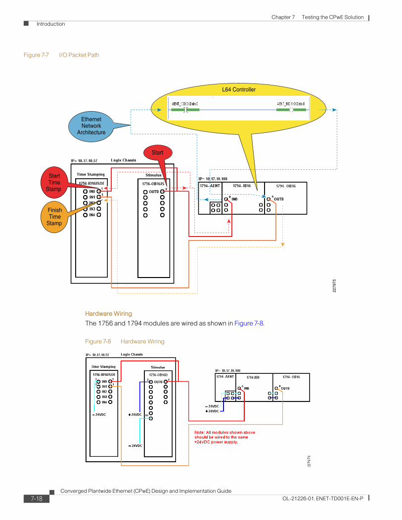
Chapter 7 Testing the CPwE Solution Introduction
Figure 7-7 I/O Packet Path
Hardware Wiring
The 1756 and 1794 modules are wired as shown in Figure 7-8.
Figure 7-8 Hardware Wiring
L64 Controller
EthernetNetwork
Architecture
Start
StartTime
Stamp
FinishTime
Stamp
2279
75
7-18Converged Plantwide Ethernet (CPwE) Design and Implementation Guide
OL-21226-01, ENET-TD001E-EN-P

Chapter 7 Testing the CPwE Solution Test Execution
Test Measurements
In this test, the IACS application measures the amount of time it takes to transmit a piece of information from the controller to the IO module via the EtherNet/IP network versus directly transmitting the information via hardwires between the IO module and controller, the SOE Time Stamp Difference Test Data. The time stamp difference is recorded in millisecond (ms) increments, for example if the SOE Time Stamp Data value received from the controller is 2.438 this value falls between 2 and 3ms so the 2ms bucket will get a value of (1) added to its field. If the SOE Time Stamp Data value is 10.913 this value falls between 10 and 11ms so the 10ms bucket will get a value of (1) added to its field. Based on this data, a minimum, maximum, and averages value are calculated. The average time stamp difference represents the average application latency. Each test run collected 300,000 samples and took about 8 to 10 hours to collect.
Figure 7-9 represents an example set of test results from screw-to-screw test run.
Figure 7-9 Test Results from an 8-switch Ring topology with MSTP and copper uplinks, Short-path
Test ExecutionThis section describes the key steps performed to execute the tests conducted for CPwE. The two key test types are network resiliency and application latency and jitter.
Network ResiliencyThis section describes the test case execution for the network resiliency testing. Note that this section describes the test cases for the ring topology. Some minor modifications to these must be done for redundant star topology, notably that the link disrupted (virtually or physically) is between the IES-8 and 3750-stack switches, as all the industrial Ethernet switches were connected to the distribution switch in this test suite.
7-19Converged Plantwide Ethernet (CPwE) Design and Implementation Guide
OL-21226-01, ENET-TD001E-EN-P

Chapter 7 Testing the CPwE Solution Test Execution
This section does not describe the setup steps as we followed the design and implementation recommendations for Cell/Area zones described in Chapter 3, “CPwE Solution Design—Cell/Area Zone” and Chapter 5, “Implementing and Configuring the Cell/Area Zone.”
Test Cases
Eight tests cases were outlined for the network resiliency test. Table 7-11 to Table 7-18 list the steps to execute these test cases. The tables apply to the 8-switch ring, MSTP, copper-uplinks test suite. The steps were slightly varied for the redundant star topology, for example, the link between IES-8 and the distribution switch was disconnected/shutdown or reconnected for test cases 1 through 4.
7-20Converged Plantwide Ethernet (CPwE) Design and Implementation Guide
OL-21226-01, ENET-TD001E-EN-P

Chapter 7 Testing the CPwE Solution Test Execution
Table 7-11 Test Case RMC8-1
Test Case RMC8-1 Bring the connection between IES-7 and IES-8 down and capture convergence times
Test Procedures 1. Verify that Switch 1 of the 3750 stack is the Stack Master
CZ-C3750-1#show switch H/W CurrentSwitch# Role Mac Address Priority Version State---------------------------------------------------------*1 Master 001a.6d5f.ef80 15 0 Ready 2 Member 001a.6d5f.e380 2 0 Ready
2. Verify that the 3750 Stack is root and that before the failure, STP is blocking between IES-4 and IES-5
IES-5#show spanning-tree mst ##### MST0 vlans mapped: 1-4094Bridge address 0021.1c30.8a00 priority 32768 (32768 sysid 0)Root address 001a.6d5f.e380 priority 24576 (24576 sysid 0) port Gi1/2 path cost 0 Regional Root address 001a.6d5f.e380 priority 24576 (24576 sysid 0) internal cost 80000 rem hops 16Operational hello time 2, forward delay 15,max age 20,txholdcount 6 Configured hello time 2, forward delay 15,max age 20,max hops 20 Interfac Role Sts Cost Prio.Nbr Type------------ ---- --- --------- -------- ----------Gi1/1 Altn BLK 20000 128.1 P2p Gi1/2 Root FWD 20000 128.2 P2p Fa1/1 Desg FWD 200000 128.3 P2p Edge Fa1/2 Desg FWD 200000 128.4 P2p Edge Fa1/3 Desg FWD 200000 128.5 P2p Edge Fa1/4 Desg FWD 200000 128.6 P2p Edge Fa2/1 Desg FWD 200000 128.7 P2p Edge
3. From the CLI of IES-8, identify the switch port connecting to IES-7
4. Prepare Ixia by Clearing All Statistics
5. Click on the Start Transmit button on the IXIA
6. From IES-8, shutdown the port connecting From IES-7
IES-8(config)#interface gigabitEthernet 1/1IES-8(config-if)#shutdown
7. Wait for the test to complete
8. Document resultsExpected Results
• When a failure occurs between IES-7 and IES-8, the connection between IES-4 and IES-5 should go to forwarding traffic.
• The IXIA streams should measure network convergence, for STP times >100 ms are expected
• The peer-to-peer application sensitivity measurement should register as the application times-out and restores connections when network convergence is complete.
7-21Converged Plantwide Ethernet (CPwE) Design and Implementation Guide
OL-21226-01, ENET-TD001E-EN-P

Chapter 7 Testing the CPwE Solution Test Execution
Table 7-12 Test Case RMC8-2
Test Case RMC8-2 Restore the connection between IES-7 and IES-8 back up and capture convergence times
Test Procedures 1. From the CLI of IES-8, identify the switch port connecting to IES-7.
2. Prepare Ixia by Clearing All Statistics.
3. Click on the Start Transmit button on the IXIA
4. From IES-8, enable the port connecting From IES-7
IES-8(config)#interface gigabitEthernet 1/1IES-8(config-if)#no shutdown
5. Wait for the test to complete.
6. Document results.Expected Results • When the link between IES-7 and IES-8 is restored Spanning Tree should be once
again blocking between IES-4 and IES-5.
• The IXIA streams should measure network convergence, for STP times > and < 100ms are expected.
• The peer-to-peer application sensitivity measurement may register as the application times-out and restores connections when network convergence is complete.
Table 7-13 Test Case RMC8-3
Test Case RMC8-3 Physically Disconnect IES-7 and IES-8 and capture convergence times
Test Procedures 1. Verity that before the failure, STP is blocking between IES-4 and IES-5.
2. From the CLI of IES-8, identify the switch port connecting to IES-7.
3. Prepare Ixia by Clearing All Statistics.
4. Click on the Start Transmit button on the IXIA.
5. Disconnect the cable between IES-7 and IES-8.
6. Wait for the test to complete.
7. Document results.Expected Results • When a failure occurs between IES-7 and IES-8, the connection between IES-4 and
IES-5 should go to forwarding traffic.
• The IXIA streams should measure network convergence, for STP times >100 ms are expected.
• The peer-to-peer application sensitivity measurement should register as the application times-out and restores connections when network convergence is complete.
7-22Converged Plantwide Ethernet (CPwE) Design and Implementation Guide
OL-21226-01, ENET-TD001E-EN-P

Chapter 7 Testing the CPwE Solution Test Execution
Table 7-14 Test Case RMC8-4
Test Case RMC8-4 Reconnect the cable between IES-7 and IES-8 back up and capture convergence times
Test Procedures 1. Prepare Ixia by Clearing All Statistics.
2. Click on the Start Transmit button on the IXIA.
3. Reconnect the cable between IES-7 and IES-8.
4. Wait for the test to complete.
5. Document results.Expected Results • When the link between IES-7 and IES-8 is restored Spanning Tree should be once
again blocking between IES-4 and IES-5.
• The IXIA streams should measure network convergence, for STP times > and < 100ms are expected.
• The peer-to-peer application sensitivity measurement may register as the application times-out and restores connections when network convergence is complete.
Table 7-15 Test Case RMC8-5
Test Case RMC8-5 Disconnect the Root Switch (3750)
Test Procedures 1. Verify that Switch 1 of the 3750 stack is the Stack Master and root.
CZ-C3750-1#show switch H/W CurrentSwitch# Role Mac Address Priority Version State---------------------------------------------------------*1 Master 001a.6d5f.ef80 15 0 Ready 2 Member 001a.6d5f.e380 2 0 Ready
2. Verity that before the failure, STP is blocking between IES-4 and IES-5.
3. Prepare Ixia by Clearing All Statistics.
4. Click on the Start Transmit button on the IXIA.
5. Virtually shut the links between the CZ-37500 and IES-1 and IES-8.
CZ-C3750-1(config)#interface range GigabitEthernet 1/0/5, GigabitEthernet 2/0/5 CZ-C3750-1(config-if-range)#shutdownGig 1/0/5 is connected to IES-1Gig 2/0/5 is connected to IES-8
6. Wait for the test to complete.
7. Document results.Expected Results • When the root switch is disconnected, a STP convergence takes place and a new
switch needs to be elected as the new root.
• The connection between IES-4 and IES-5 should go to forwarding traffic.
• The IXIA streams should measure network convergence, for STP times >100 ms are expected.
• The peer-to-peer application sensitivity measurement should register as the application times-out and restores connections when network convergence is complete.
7-23Converged Plantwide Ethernet (CPwE) Design and Implementation Guide
OL-21226-01, ENET-TD001E-EN-P

Chapter 7 Testing the CPwE Solution Test Execution
Table 7-16 Test Case RMC8-6
Test Case RMC8-6 Reconnect the Root Switch (3750)
Test Procedures 1. Prepare Ixia by Clearing All Statistics.
2. Click on the Start Transmit button on the IXIA.
3. Virtually restore the links between the CZ-37500 and IES-1 and IES-8.
CZ-C3750-1(config)#interface range GigabitEthernet 1/0/5, GigabitEthernet 2/0/5 CZ-C3750-1(config-if-range)# no shutdownGig 1/0/5 is connected to IES-1Gig 2/0/5 is connected to IES-8
4. Wait for the test to complete.
5. Document results.Expected Results • When the connections are restored, the 3750 stack regains the role of STP root and
IGMP querier.
• The connection between IES-4 and IES-5 is once again blocked.
• The IXIA streams should measure network convergence, for STP times > and < 100ms are expected.
• The peer-to-peer application sensitivity measurement may register as the application times-out and restores connections when network convergence is complete.
7-24Converged Plantwide Ethernet (CPwE) Design and Implementation Guide
OL-21226-01, ENET-TD001E-EN-P

Chapter 7 Testing the CPwE Solution Test Execution
Table 7-17 Test Case RMC8-7
Test Case RMC8-7 Bring Stack Master Down
Test Procedures 1. Configure the stack to boot manually during the next boot cycle.
#Configure terminal(config)# boot manual
2. Identify the Stack Master in the 3750 stack. In this case, Switch #1 is the master.
CZ-C3750-1#show switch H/W CurrentSwitch# Role Mac Address Priority Version State---------------------------------------------------------*1 Master 001a.6d5f.ef80 15 0 Ready 2 Member 001a.6d5f.e380 2 0 Ready
3. Verity that before the failure, STP is blocking between IES-4 and IES-5.
4. Prepare Ixia by Clearing All Statistics.
5. Click on the Start Transmit button on the IXIA.
6. Reload the Stack Master. In this case, Slot #1, Switch #1 is the master.
3750#reload slot 1
7. Wait for the test to complete.
8. Document results.Expected Results • When the Stack Master fails, a new switch needs to be elected as the Stack Master
and a connection fails, creating a STP event and to re-elect a new STP root.
• The connection between IES-4 and IES-5 will go to forwarding traffic.
• The IXIA streams should measure network convergence, for STP times >100 ms are expected.
• The peer-to-peer application sensitivity measurement should register as the application times-out and restores connections when network convergence is complete.
7-25Converged Plantwide Ethernet (CPwE) Design and Implementation Guide
OL-21226-01, ENET-TD001E-EN-P

Chapter 7 Testing the CPwE Solution Test Results Summary
Application-level Latency and JitterThe application-level latency tests or screw-to-screw were performed on the above discussed test suites. Two test cases were performed: a short and long path. The long-path test case was executed after introducing a failure in the topology and then conducting the test run. An Excel spreadsheet with embedded macros was developed to start the test and collect the application latency statistics. The other IACS devices and applications were in operations during the test. No Ixia traffic generation was introduced or measured during these tests.
Test Results Summary This section summarizes the key findings from the tests performed. This section is intended to summarize observations made from the test analysis documented in Appendix B, “Test Result Analysis” and Appendix C, “Complete Test Data.” Some of the findings were included in earlier chapters to support key recommendations. The key objectives set forth for this test plan included to test and measure impact of the following:
• Network scalability in terms of the number of switches and number of end-devices, in particular the impact of a larger network on network convergence
• Media, in particular the use of fiber versus copper for inter-switch uplinks
• Network topology (ring versus redundant star)
• Network resiliency protocol, in particular between Spanning Tree versions, EtherChannel, and Flex Links
Table 7-18 Test Case RMC8-8
Test Case RMC8-8 Add the switch back to the stack
Test Procedures 1. Prepare Ixia by Clearing All Statistics.
2. Click on the Start Transmit button.
3. Boot up the switch.
switch: boot flash:/c3750-advipservicesk9-mz.122-46.SE/c3750-advipservicesk9-mz.122-46.SE.bin
4. Wait for the test to complete.
5. Document results.Expected Results • Since there is already a Stack Master switch, no changes will take place to the stack,
but the connection will be restored.
• When the link is restored Spanning Tree will be once again blocking between IES-4 and IES-5.
• The IXIA streams should measure network convergence, for STP times > and < 100ms are expected.
• The peer-to-peer application sensitivity measurement may register as the application times-out and restores connections when network convergence is complete.
7-26Converged Plantwide Ethernet (CPwE) Design and Implementation Guide
OL-21226-01, ENET-TD001E-EN-P

Chapter 7 Testing the CPwE Solution Test Results Summary
• Network behavior in a variety of failure/restore scenarios, so customers and implementers can make decisions about how to react and potentially when to restore failed links or devices, in terms of network convergence, application sensitivity and overall system latency and jitter.
The key observations can be summarized into the following points:
• Scalability (number of switches)—The size of the ring impacts (slows down) the network convergence in link disruption (physical or software) and stack master down test cases, although with the variability due to the copper media, this impact is difficult to quantify.
• Scalability (number of switches)—The number of switches in a redundant star did not have an impact on the network convergence.
• Scalability (number of switches)—Number of switches in the different network topologies tested did not create a large difference in application-level latency (screw-to-screw)
• Scalability (number of endpoints)—The number of endpoints tested had an impact on the Spanning Tree topologies, although this impact was less significant than either media or topology and therefore difficult to measure. There was no significant negative impact of the number of endpoints simulated in Flex Links or EtherChannel test suites.
• Media—Fiber uplink topologies converged significantly faster and with less variability than copper uplink topologies, all other conditions the same. The signal loss is detected much more quickly with fiber media than with copper.
• Topology—Redundant star topologies converged more quickly than ring topologies. This is due to the fact that a redundant star only has two uplinks (three switches) maximum in the path between any two endpoints.
• Resiliency—EtherChannel and Flex Links are faster than Spanning Tree in redundant star topologies. EtherChannel and Flex Links with fiber uplinks converged fast enough to avoid “time-critical” application timeouts; i.e. consistent recovery in less than 100ms. EtherChannel convergence times approached or exceeded 100ms in a few cases, so some application timeouts may occur, but were not experienced in the testing, With the exception of ring with copper uplinks, all other topology and resiliency protocol combinations converged fast enough for information/process applications (i.e., generally the network recovers within 1000ms).
• Resiliency—Flex Links had better network convergence than EtherChannel, especially with multicast traffic, in a range of test cases. This is due to the multicast fast convergence feature in FlexLinks.
• Network Behavior—Restoring connections (physically or virtually) and restoring switches to the stack have little impact. Network convergence was often fast enough to avoid time-critical application timeouts. One notable exception was EtherChannel did have slow network convergence when a switch was restored to the stack.
7-27Converged Plantwide Ethernet (CPwE) Design and Implementation Guide
OL-21226-01, ENET-TD001E-EN-P

Chapter 7 Testing the CPwE Solution Test Results Summary
7-28Converged Plantwide Ethernet (CPwE) Design and Implementation Guide
OL-21226-01, ENET-TD001E-EN-P

Converged Plantwide Ethernet (CPwOL-21226-01, ENET-TD001E-EN-P
C H A P T E R 8
CIP MotionIntroductionThis chapter describes the implementation of CIP Motion on EtherNet/IP and extends the design recommendations described in Chapter 3, “CPwE Solution Design—Cell/Area Zone” and Chapter 5, “Implementing and Configuring the Cell/Area Zone.” Motion control systems are common within cell/area zone manufacturing applications such as packaging, pick-n-place, converting, assembly, and robotics. Motion control systems primarily control the position and velocity of servo motors. To support this, the cell/area Industrial Automation and Control System (IACS) network infrastructure must be capable of the following main tasks:
• Managing time synchronization services
• Delivering data between devices in a timely manner
As noted in earlier chapters, the cell/area zone is where the IACS end devices connect into the cell/area IACS network. Careful planning is required to achieve the optimal design and performance from both the cell/area IACS network and IACS device perspective. This extension of the Converged Plantwide Ethernet (CPwE) architectures focuses on EtherNet/IP, which is driven by the ODVA Common Industrial Protocol (CIP) [see IACS Communication Protocols, page1-26], and in particular is tested with Rockwell Automation devices, controllers, and applications. CIP Motion on EtherNet/IP uses the CIP Application layer protocol in conjunction with CIP Sync to handle the required time synchronization services on the EtherNet/IP cell/area IACS network. See CIP Sync for Real-Time Motion Control, page 8-5. Additionally, CIP Motion uses standard 100-MB switched Ethernet as well as standard Layer 2 (CoS) and Layer 3 (DSCP) quality of service (QoS) services cell/area to prioritize the motion traffic above other types of traffic for timely data delivery.
8-1E) Design and Implementation Guide

Chapter 8 CIP Motion EtherNet/IP for Motion Control
This chapter outlines the key requirements and technical considerations for real-time motion control applications using CIP Motion on EtherNet/IP within the cell/area zone. This chapter includes the following topics:
• EtherNet/IP for Motion Control, page 8-2
• CIP Sync for Real-Time Motion Control, page 8-5
• Prioritization Services—QoS, page 8-5
• EtherNet/IP Embedded Switch Technology, page 8-10
• CIP Motion Reference Architectures, page 8-11
• CIP Motion Reference Architecture Testing, page 8-28
• Design Recommendations, page 8-37
• Detailed Test Results, page 8-40
EtherNet/IP for Motion ControlThe EtherNet/IP network controls many applications, including I/O-to-AC drive control, human-machine interface (HMI) communications, and controller-to-controller interlocking, and data collection and integration with IT and manufacturing execution systems (MES). With CIP Sync and CIP Motion technologies, EtherNet/IP now handles real-time control for motion control applications, adding the final element required to make it provide a complete fieldbus solution.
The EtherNet/IP network is not new to the industrial marketplace. Products have been shipping for more than a decade, with millions of nodes installed worldwide. EtherNet/IP network architecture is well-established. Now that real-time control for motion is available over EtherNet/IP, existing installations can absorb and incorporate this new capability with few changes to existing devices and topologies.
CIP Motion Uses Standard, Unmodified Ethernet
How can this technology be leveraged to help avoid the obsolescence of existing installations while adding real-time motion control to the network’s capabilities? The key lies in its adherence to existing Ethernet standards.
In its strictest definition, the term Ethernet refers to the Physical and the Data Link layers of the OSI networking model; it does not, historically, refer to the Network layer, the Transport layer, or the Application layer. For this reason, many networks claim Ethernet compliance and openness despite the fact that many of the standard protocols in the other layers of the stack are not used. Although the term Ethernet has been applied to a very wide range of such networks, most Ethernet applications have also standardized on the Network and Transport layers of this model to communicate. Many of the software applications that exist today rely on the TCP or UDP protocols (Layer 4) as well as the IP protocol (Layer 3) to exchange data and information. These include applications such as e-mail, web pages, voice and video, and a host of other very popular applications, as shown in Figure 8-1.
8-2Converged Plantwide Ethernet (CPwE) Design and Implementation Guide
OL-21226-01, ENET-TD001E-EN-P

Chapter 8 CIP Motion EtherNet/IP for Motion Control
Figure 8-1 CIP Motion Uses Standard Network Stack Implementation
As EtherNet/IP has been developed, the standards and common protocols typically associated with Ethernet installations and applications have been maintained. In fact, CIP is an Application layer that resides on top of these layers and is portable enough to be used by the EtherNet/IP, DeviceNet, ControlNet, and CompoNet networks. Because of this, backward compatibility becomes more achievable, and current designs are more likely to avoid obsolescence. This is why real-time motion control is possible without redesigning the entire network or causing major design changes in existing EtherNet/IP installations.
Traditional Approach to Motion Control Networking
The traditional approach to handling real-time control in a motion environment is to schedule a device's time on the network. In this model, a master device establishes a marker on the network by which all other devices are synchronized (see Figure 8-2). This sync message defines the start of an update cycle. During this update cycle, the controller and drives send critical reference and feedback information. All members of the network are allocated a time slice of network time to send their data. All devices must be finished with their updates during their time slice.
Figure 8-2 Traditional Motion Approach Requires a Scheduled Network
The aggregate of all the devices’ time slots results in a total update cycle, which dictates the schedule that the master device uses to resend the next marker or sync message. During system configuration, as drives are added to the network, network timing is calculated, the master is given its schedule, and the timing for the system is set in place. After this schedule has been established,
2901
24
Application Layer
File T
ransfe
r
Web
Voice
/Vide
o
Serve
rs
Manag
emen
t
Transport Layer
Internet Layer
Data Link Layer
Physical LayerIEEE 802.3
TCP/IP Suite
Application Layer FTP SMTP HTTP
IP
CSMA/CD
Physical Layer
VOIP DNS SNMP
TCP UDP
CIP
Indus
trial
Cont
rols
2901
49
Drive 1Drive 1 Drive 2 Drive 3Sync Sync
Update Cycle
Drive1
Drive2
Drive3
Controller
MotionController
Drive 2
8-3Converged Plantwide Ethernet (CPwE) Design and Implementation Guide
OL-21226-01, ENET-TD001E-EN-P
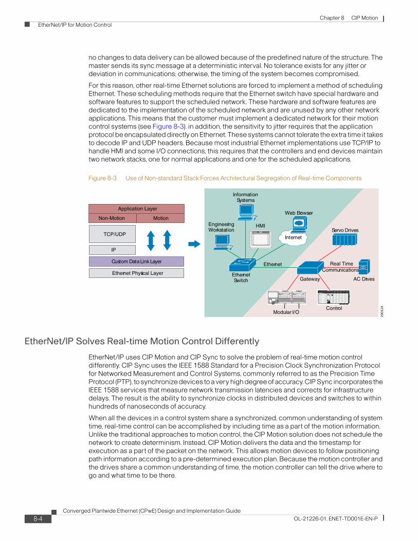
Chapter 8 CIP Motion EtherNet/IP for Motion Control
no changes to data delivery can be allowed because of the predefined nature of the structure. The master sends its sync message at a deterministic interval. No tolerance exists for any jitter or deviation in communications; otherwise, the timing of the system becomes compromised.
For this reason, other real-time Ethernet solutions are forced to implement a method of scheduling Ethernet. These scheduling methods require that the Ethernet switch have special hardware and software features to support the scheduled network. These hardware and software features are dedicated to the implementation of the scheduled network and are unused by any other network applications. This means that the customer must implement a dedicated network for their motion control systems (see Figure 8-3). in addition, the sensitivity to jitter requires that the application protocol be encapsulated directly on Ethernet. These systems cannot tolerate the extra time it takes to decode IP and UDP headers. Because most industrial Ethernet implementations use TCP/IP to handle HMI and some I/O connections, this requires that the controllers and end devices maintain two network stacks, one for normal applications and one for the scheduled applications.
Figure 8-3 Use of Non-standard Stack Forces Architectural Segregation of Real-time Components
EtherNet/IP Solves Real-time Motion Control Differently
EtherNet/IP uses CIP Motion and CIP Sync to solve the problem of real-time motion control differently. CIP Sync uses the IEEE 1588 Standard for a Precision Clock Synchronization Protocol for Networked Measurement and Control Systems, commonly referred to as the Precision Time Protocol (PTP), to synchronize devices to a very high degree of accuracy. CIP Sync incorporates the IEEE 1588 services that measure network transmission latencies and corrects for infrastructure delays. The result is the ability to synchronize clocks in distributed devices and switches to within hundreds of nanoseconds of accuracy.
When all the devices in a control system share a synchronized, common understanding of system time, real-time control can be accomplished by including time as a part of the motion information. Unlike the traditional approaches to motion control, the CIP Motion solution does not schedule the network to create determinism. Instead, CIP Motion delivers the data and the timestamp for execution as a part of the packet on the network. This allows motion devices to follow positioning path information according to a pre-determined execution plan. Because the motion controller and the drives share a common understanding of time, the motion controller can tell the drive where to go and what time to be there.
2901
24
Non-Motion
IP
Custom Data Link Layer
Application Layer
Ethernet Physical Layer
EngineeringWorkstation
InformationSystems
HMI
Motion
TCP/UDPInternet
Web Browser
Ethernet Real TimeCommunications
EthernetSwitch Gateway
Modular I/OControl
AC Drives
Servo Drives
8-4Converged Plantwide Ethernet (CPwE) Design and Implementation Guide
OL-21226-01, ENET-TD001E-EN-P

Chapter 8 CIP Motion CIP Sync for Real-Time Motion Control
The method that CIP Motion uses to control motion is the same method used every day to attend meetings and events. In both cases, each member of the group is given information about where to go (position) and what time to be at that specific location. Because each member of the group has a watch or clock, all members arrive at the proper position at the specified time. The time at which each member receives the message about where and when to be at a location can vary. As long as the message is received early enough to allow the members to arrive on time, each member arrives in coordination with all other members. This also means that the data delivery on the Ethernet network does not need to be scheduled; only that the data must arrive just early enough to have all devices coordinate their position.
CIP Sync for Real-Time Motion ControlThe previous section described how CIP Motion uses time as a necessary component of the motion information to synchronize multiple motion devices in the same system. The use of time as a part of the motion packet allows CIP Sync to coordinate time on EtherNet/IP.
CIP Sync is the name given to time synchronization services for CIP. These services allow accurate real-time synchronization of devices and controllers connected over networks that require time-stamping, sequence of events recording, distributed motion control, and other highly distributed applications that need increased control coordination.
CIP Sync is based on the IEEE 1588 standard, PTP. The standard is designed for LANs such as Ethernet, but is not limited to the Ethernet network. PTP provides a standard mechanism to synchronize clocks across a network of distributed devices.
For more information on CIP Sync technology, including such concepts as PTP, Device-level Ring (DLR), and clock types, see the Rockwell Automation publication IA-AT003, “Integrated Architecture and CIP Sync Configuration and Application Technique”, at the following URL: http://literature.rockwellautomation.com/idc/groups/literature/documents/at/ia-at003_-en-p.pdf
and Rockwell Automation publication ENET-AP005, “EtherNet/IP Embedded Switch Technology Linear and Device-level Ring Topologies Application Technique” at the following URL:
http://literature.rockwellautomation.com/idc/groups/literature/documents/ap/enet-ap005_-en-p.pdf
Prioritization Services—QoSA traditional Ethernet network is based on the best-effort data processing mechanism, in which all the traffic gets serviced based on the first-in-first-out (FIFO) principle. However, not all network traffic is created equal, nor should users treat it equally. For example, control data (that is, CIP Sync, CIP Motion, and time-critical I/O) is more sensitive to latency and jitter than information data, such as web traffic or file transfers. To minimize application latency and jitter, control data should have priority within the cell/area zone. This prioritization is accomplished by implementing QoS, which gives preferential treatment to some network traffic at the expense of others. QoS prioritizes traffic into different service levels and provides preferential forwarding treatment to some data traffic at the expense of lower-priority traffic.
When network QoS is implemented, the network traffic is prioritized according to its relative importance and congestion-management and congestion-avoidance techniques are used to provide preferential treatment to priority traffic. Implementing QoS makes network performance more predictable and bandwidth utilization more effective.
8-5Converged Plantwide Ethernet (CPwE) Design and Implementation Guide
OL-21226-01, ENET-TD001E-EN-P

Chapter 8 CIP Motion CIP Sync for Real-Time Motion Control
The CPwE solution recommends a QoS implementation designed and suited for automation and control applications, including Motion and Time Synchronization. By following the recommended design and implementation guides, QoS is automatically configured to these pre-determined settings.
Customers can choose to change or modify the QoS configuration. Before modifying QoS in a particular area, use a multidisciplinary team of operations, engineering, IT, and safety professionals to establish a QoS policy. This policy should support the needs of operations, including when and where to apply QoS. Additionally, the multidisciplinary team should understand that this policy may differ from the enterprise-wide QoS policy. Enterprise-wide QoS policies commonly give priority to voice over IP (VoIP), a voice transmission protocol, which may not be as important in an individual area. and may prioritize automation and control traffic very low, thereby negatively impacting automation and control performance.
QoS Principles and OperationThis section provides an overview of the QoS concepts and techniques used for motion applications. See Quality-of-Service (QoS), page 3-63 for more information on implementing QoS for automation and control applications.
The QoS implementation is based on the Differentiated Services (DiffServ) model, a standard from the Internet Task Force (ITF). This standard provides different treatment of traffic classes based on their characteristic behavior and tolerance to delay, loss, and jitter. The overall model is defined in RFC 2475, “An Architecture for Differentiated Services”.
DiffServ allows nodes (typically switches and routers) to service packets based on their DiffServ Code Point (DSCP) values. For CIP Motion/CIP Sync applications, the originating devices mark the DSCP values. These values are carried in the IP packet header, using the 6 upper bits of the IP type of service (ToS) field to carry the classification information, as shown in Figure 8-4.
Figure 8-4 Implementation of QoS Within an IPv4 Packet
Note Classification can also be carried in the Layer 2 frame (802.1D). However, Rockwell Automation’s implementation is based on Layer 3.
2901
27
7 6 5 4 3 2 1 0
DiffServ Code Point (DSCP) IP ECN
IP Precedence Unused Standard IPv4
DiffServ Extensions
ID Offset TTL Proto FCS IP SA IP DA DataLenVersionLength
ToSByte
IPv4 Packet
8-6Converged Plantwide Ethernet (CPwE) Design and Implementation Guide
OL-21226-01, ENET-TD001E-EN-P

Chapter 8 CIP Motion CIP Sync for Real-Time Motion Control
As a general rule, QoS operation involves the following actions:
• Classification—Examining packets and determining the QoS markings (for example, DSCP and/or 802.1D priority). Many switches can also be configured to classify packets based on TCP or UDP port number, VLAN, or the physical ingress port.
• Policing—Per configuration, determining whether the incoming packet is within the profile or outside the profile.
• Marking—The incoming packet may be further marked (for example, upgraded or downgraded).
• Queuing and scheduling—Determining into which queue to place the packet, and servicing queues according to the configured scheduling algorithm and parameters. Switches and routers may support scheduling on a strict priority basis, round-robin basis, or other.
For more information, see the “Configuring QoS” section of the IE 3000 Software Configuration Guide, available at the following URL: http://www.cisco.com/en/US/docs/switches/lan/cisco_ie3000/software/release/12.2_50_se/configuration/guide/swqos.html#wp1284809
In a network, the above QoS actions can be used to provide levels of service appropriate to the different needs of traffic types. Tolerance to loss, delay, and jitter are the primary factors in determining the QoS requirements for different types of traffic.
Table 8-1 shows the tolerance to loss, delay, and jitter for EtherNet/IP-related traffic.
.Table 8-1 Loss, Delay, Jitter Tolerance for EtherNet/IP-related Traffic Types
Traffic TypeTraffic Characteristics Tolerance to
Loss Delay Jitter
IEEE 1588 Fixed size messages, 44 or 64 bytes payload.
Produced on a cyclic basis, once per second.
High performance applications not tolerant to loss.
PTP compensates for delays in the infrastructure.
+/-100 ns.
CIP Motion Fixed size messages, typically 80–220 bytes.
Usually produced according to a cyclic rate.
High performance applications target up to 100 axes in 1 ms.
Can tolerate occasional loss of up to 3 consecutive packets.
Target: 0 packet loss.
For high performance applications, less than 100 μs.
Up to the maximum delay.
CIP I/O Fixed size messages, typically 100 to 500 bytes.
Usually produced according to a cyclic rate. Can also be produced on application change of state.
Typical cyclic rate per stream: 1 to 500 ms or greater.
Application dependent. Generally can tolerate occasional loss.
CIP connection typically times out if 4 consecutive packets lost.
Target: 0 packet loss.
Application dependent. Tolerance proportional to the packet rate.
Target: < 25% of the packet interval.
Application dependent. Generally can tolerate jitter up to the maxim tolerable delay.
8-7Converged Plantwide Ethernet (CPwE) Design and Implementation Guide
OL-21226-01, ENET-TD001E-EN-P

Chapter 8 CIP Motion CIP Sync for Real-Time Motion Control
Mapping CIP Traffic to DSCP and 802.1DBased on Table 8-1, different priority traffic is assigned different priority values. Table 8-2 shows the default ODVA-standard priority values for CIP and IEEE 1588 traffic. The priority values can be changed via the QoS Object.
CIP Safety I/O Fixed messages, typically on the order of 16 bytes payload.
Produced according to a cyclic rate.
Typical cyclic rate: 5 to 10 ms or greater.
Can tolerate occasional loss of 1 packet in a safety period (1 out of 4 transmissions).
Dependent on the packet rate; in general can tolerate delay of 5 ms.
Up to the maximum delay.
HMI Messaging Variable size messages.
Typical size: 100 to 500 bytes; likely to be larger in the future.
Produced under application control. Can be at regular cyclic intervals, or based on application state or user action.
Typical cyclic rate: 0.5 to 5 sec or greater.
Can tolerate packet loss so long as TCP connection remains.
Can tolerate delay as long as the TCP connection remains.
Can tolerate large degree of jitter.
Table 8-1 Loss, Delay, Jitter Tolerance for EtherNet/IP-related Traffic Types (continued)
Traffic TypeTraffic Characteristics Tolerance to
Loss Delay Jitter
Table 8-2 DSCP and 802.1D Values
Traffic Type CIP PriorityDSCP Enabled by Default
802.1D Priority Disabled by Default CIP Traffic Usage
PTP event (IEEE 1588) N/A 59
(‘111011’)
7 PTP event messages, used by CIP Sync
PTP management (IEEE 1588)
N/A 47
(‘101111’)
5 PTP event messages, used by CIP Sync
CIP class 0/1 Urgent (3) 55
(‘110111’)
6 CIP Motion
Scheduled (2) 47
(‘101111’)
5 Safety I/O
I/O
High (1) 43
(‘101011’)
5 I/O
Low (0) 31
(‘011111’)
3 Not recommended
CIP UCMM
CIP Class 3
All 27
(‘011011’)
3 CIP messaging
8-8Converged Plantwide Ethernet (CPwE) Design and Implementation Guide
OL-21226-01, ENET-TD001E-EN-P

Chapter 8 CIP Motion CIP Sync for Real-Time Motion Control
QoS Support in the InfrastructureMarking packets with DSCP or 802.1D priorities is not useful unless the network infrastructure is able to provide service based on those markings. Fortunately, most managed switches and routers support multiple queues and differentiation based on 802.1D, and many support DSCP.
Figure 8-5 and Figure 8-6 illustrate a single-queue switch and a multiple-queue switch.
Figure 8-5 Single Queue Switch
Figure 8-6 Multiple Queue Switch
In the single-queue switch, packets of all priorities are intermingled in a single queue, first-come, first-served. Higher priority packets may have to wait as lower priority packets are serviced.
In a multiple-queue switch, packets can be directed to different queues based on their priority markings. The different queues are then serviced according to a scheduling algorithm, such that higher priority packets are given precedence over lower priority packets. Often, one of the queues can be assigned strict priority where any packet in that queue is automatically serviced next.
Many switches and routers provide extensive configuration options, allowing different mappings of priorities to queues, selection of buffer space, and different scheduling algorithms (may vary by vendor).
2901
29
Priority
High Medium Low Best Effort
Ingress Ports
0
1
2
0
1
2
Egress Ports
2901
28
Priority
High Medium Low Best Effort
Ingress Ports
0
1
2
0
1
2
Egress Ports
8-9Converged Plantwide Ethernet (CPwE) Design and Implementation Guide
OL-21226-01, ENET-TD001E-EN-P

Chapter 8 CIP Motion EtherNet/IP Embedded Switch Technology
QoS Support in the Rockwell Automation Embedded Switch Technology (DLR and Linear Topologies)
Rockwell Automation has developed a three-port switch for integration into many of its EtherNet/IP-based products. This switch has two external ports for daisy chaining and one port integrated within the product. The switch offers IEEE 1588 transparent clock functionality for re-phasing of the clocks as well as QoS functionality. It also supports the Beacon protocol, used to manage the traffic in a closed-loop ring.
The embedded switch technology enforces QoS based on IP DSCP. The embedded switch implements four prioritized transmit queues per port, as follows:
• Frames received with DSCP 59 are queued in highest priority transmit queue 1.
• Frames received with DSCP 55 are queued in second highest priority transmit queue 2.
• Frames received with DSCP 47 and 43 are queued in third highest priority transmit queue 3
• Frames received with other DSCP values are queued in lowest priority transmit queue 4.
In addition, ring protocol frames are queued in highest priority queue 1. When a port is ready to transmit the next frame, the highest priority frame is chosen from the current set of queued frames for transmission based on strict priority ordering. Within a given priority queue, frames are transmitted in FIFO order. (See Table 8-3.)
.
Note Implementation of QoS in the Stratix 8000 switches differs from QoS implementation for embedded switches. For more information on QoS implementation, see Chapter 3, “CPwE Solution Design—Cell/Area Zone.”
The DSCP values are aligned with the ODVA EtherNet/IP QoS object specification. The originator of a frame, including all dual-port devices, is expected to put the correct DSCP value in the frame. Legacy single-port products may not put the correct DSCP value in the frame.
EtherNet/IP Embedded Switch TechnologyEtherNet/IP embedded switch technology incorporates a three-port switch (typically two external ports, and one internal port) into Rockwell Automation end devices, instead of directly to an external switch. This feature has also been incorporated into Rockwell Automation devices that support both CIP Sync and CIP Motion. The embedded switch technology is included in the 1756-EN2TR and 1756-EN3TR EtherNet/IP communication modules and the Kinetix 6500 servo drives. Each of the Kinetix 6500 control modules contain dual Ethernet ports. Examples of additional devices with embedded switch technology include Point I/O and ArmorBlock I/O products.
Table 8-3 Four Prioritized Transmit Queues
Class of Service DSCP Notes
Highest priority 7 59 DLR/BRP, PTP Event (IEEE 1588)
High priority 55 CIP Motion
Low priority 43, 47 I/O, Safety I/O, PTP Management (IEEE 1588)
Lowest priority 1,2,3,4,5,6 0–42,44–46,48–54,56–58,60–63 Best effort
8-10Converged Plantwide Ethernet (CPwE) Design and Implementation Guide
OL-21226-01, ENET-TD001E-EN-P

Chapter 8 CIP Motion CIP Motion Reference Architectures
Products that do not support embedded switch technology can still be integrated into a linear or ring topology with a network tap (catalog numbers 1783-ETAP, 1783-ETAP1F, 1783-ETAP2F). The taps contain a single device port and two network ports to connect into a linear or ring network topology. For more information on embedded switch technology, see the Rockwell Automation publication, ENET-AP005, “EtherNet/IP Embedded Switch Technology Application Guide”, available at the following URL: http://literature.rockwellautomation.com/idc/groups/literature/documents/ap/enet-ap005_-en-p.pdf
Support for the following EtherNet/IP embedded switch technology features are critical to both CIP Sync and CIP Motion:
• IEEE 1588 transparent clock to ensure proper time synchronization
• Beacon protocol for ring configurations
• QoS
• Internet Group Management Protocol (IGMP) for management of network traffic to ensure that critical data is delivered in a timely manner
CIP Motion Reference ArchitecturesThe following topologies were set up and validated:
• Linear
• Ring (DLR)
• Star
Linear TopologiesThis section discusses types of linear topologies.
Advantages of a linear network include the following:
• Simplifies installation by eliminating long cable runs back to a central switch
• Extends the network over a longer distance because individual cable segments can be up to 100 m
• Supports up to 50 mixed devices per line
The primary disadvantage of a linear topology is that a lost connection or link failure disconnects all downstream devices as well. To counter this disadvantage, a ring topology can be employed.
Basic Linear Topologies
The most basic network topology for a CIP Motion network is a linear topology with a point-to-point connection between the 1756-EN2T, 1756-EN2TR, or 1756-EN3TR modules and the first Kinetix 6500 drive, as shown in Figure 8-7.
8-11Converged Plantwide Ethernet (CPwE) Design and Implementation Guide
OL-21226-01, ENET-TD001E-EN-P

Chapter 8 CIP Motion CIP Motion Reference Architectures
Figure 8-7 Basic Linear Topology
Notice that the topology shown in Figure 8-7 does not require the use of an external Ethernet switch. EtherNet/IP embedded switch technology eliminates the requirement for external Ethernet switch hardware. Each of the Kinetix 6500 drives contains a dual-port switch that lets the drives be daisy-chained. Because the embedded switch technology employs a transparent clock and supports QoS and IGMP, proper time synchronization is maintained between the master and slave clocks. In addition, critical position command and drive feedback data is transmitted in a timely manner.
Note The 1756-EN2T and 1756-EN2TR modules are limited to eight configured position servo drives, while the 1756-EN3TR module is limited to 128 configured position servo drives.
Linear topology can include many types of devices on the same network, as shown in Figure 8-8.
2901
48
Kinetix 6500
ControlLogix
1756-EN2TR
NetworkInfrastructure
8-12Converged Plantwide Ethernet (CPwE) Design and Implementation Guide
OL-21226-01, ENET-TD001E-EN-P

Chapter 8 CIP Motion CIP Motion Reference Architectures
Figure 8-8 Linear Topology with Additional Devices
Devices with embedded switch technology such as POINT I/O or ArmorBlock I/O can be added to extend the topology. EtherNet/IP taps can be used to incorporate devices that do not contain embedded switch technology, such as the PowerFlex 755 drive. Devices that do not have embedded switch technology can also be added as the last device in the line, as illustrated by the PanelView terminal in Figure 8-8.
Linear/Star Topology
Network switches can also be added to the end of the line, creating a linear/star topology, as shown in Figure 8-9.
2901
32
PanelView
Kinetix 6500
ControlLogix
PowerFlex 755
Point I/O
EtherNet/IP Tap
ArmorBlock I/O
1756-EN2T or 1756-ENxTR
8-13Converged Plantwide Ethernet (CPwE) Design and Implementation Guide
OL-21226-01, ENET-TD001E-EN-P

Chapter 8 CIP Motion CIP Motion Reference Architectures
Figure 8-9 Linear/Star Topology—Linear Segment with External Switch (Star)
Devices that do not have embedded switch technology can be connected in a star topology from the switch, as illustrated by the Stratix 6000 Ethernet switch in Figure 8-9.
Star/Linear Topology
A linear segment of Kinetix 6500 drives and other devices can also be connected as a branch off of a central switch, creating a star/linear topology between the ControlLogix chassis and the first Kinetix 6500 drive, as shown in Figure 8-10.
Figure 8-10 Star/Linear Topology—Linear Segment Connected to External Switch (Star)
2901
33
Kinetix 6500
ControlLogix
1756-EN2T or 1756-ENxTR
PowerFlex 755
Point I/O
EtherNet/IP Tap
ArmorBlock I/O
PanelViewPC
PowerFlex 40
Flex I/O
Stratix 6000
2901
34
Kinetix 6500
ControlLogix
PowerFlex 755
Point I/O
EtherNet/IP Tap
ArmorBlock I/O
PanelView
PC
Stratix 8000
1756-EN2T or 1756-ENxTR
Typically a managed switchwith a transparent and/or
boundary clock, plus QoSand IGMP protocol support
8-14Converged Plantwide Ethernet (CPwE) Design and Implementation Guide
OL-21226-01, ENET-TD001E-EN-P
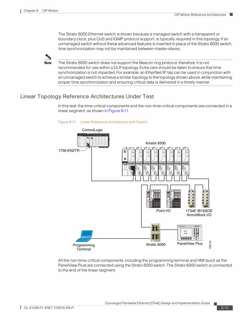
Chapter 8 CIP Motion CIP Motion Reference Architectures
The Stratix 8000 Ethernet switch is shown because a managed switch with a transparent or boundary clock, plus QoS and IGMP protocol support, is typically required in this topology. If an unmanaged switch without these advanced features is inserted in place of the Stratix 8000 switch, time synchronization may not be maintained between master-slaves.
Note The Stratix 8000 switch does not support the Beacon ring protocol; therefore, it is not recommended for use within a DLR topology. Extra care should be taken to ensure that time synchronization is not impacted. For example, an EtherNet/IP tap can be used in conjunction with an unmanaged switch to achieve a similar topology to the topology shown above, while maintaining proper time synchronization and ensuring critical data is delivered in a timely manner.
Linear Topology Reference Architectures Under Test
In this test, the time-critical components and the non-time-critical components are connected in a linear segment, as shown in Figure 8-11.
Figure 8-11 Linear Reference Architecture with Switch
All the non-time-critical components, including the programming terminal and HMI (such as the PanelView Plus) are connected using the Stratix 6000 switch. The Stratix 6000 switch is connected to the end of the linear segment.
2901
39
ControlLogix
1734E IB16SOEArmorBlock I/O
Kinetix 6500
Point I/O
PanelView PlusStratix 6000
1756-EN2TR
ProgrammingTerminal
8-15Converged Plantwide Ethernet (CPwE) Design and Implementation Guide
OL-21226-01, ENET-TD001E-EN-P
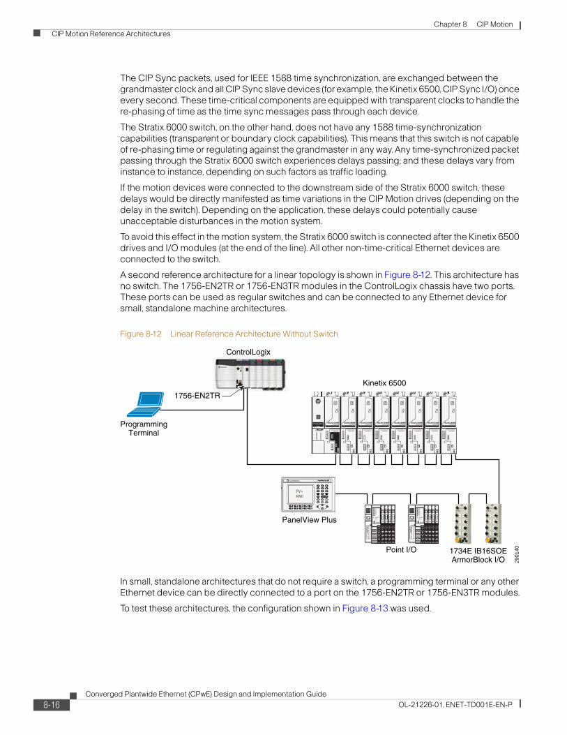
Chapter 8 CIP Motion CIP Motion Reference Architectures
The CIP Sync packets, used for IEEE 1588 time synchronization, are exchanged between the grandmaster clock and all CIP Sync slave devices (for example, the Kinetix 6500, CIP Sync I/O) once every second. These time-critical components are equipped with transparent clocks to handle the re-phasing of time as the time sync messages pass through each device.
The Stratix 6000 switch, on the other hand, does not have any 1588 time-synchronization capabilities (transparent or boundary clock capabilities). This means that this switch is not capable of re-phasing time or regulating against the grandmaster in any way. Any time-synchronized packet passing through the Stratix 6000 switch experiences delays passing; and these delays vary from instance to instance, depending on such factors as traffic loading.
If the motion devices were connected to the downstream side of the Stratix 6000 switch, these delays would be directly manifested as time variations in the CIP Motion drives (depending on the delay in the switch). Depending on the application, these delays could potentially cause unacceptable disturbances in the motion system.
To avoid this effect in the motion system, the Stratix 6000 switch is connected after the Kinetix 6500 drives and I/O modules (at the end of the line). All other non-time-critical Ethernet devices are connected to the switch.
A second reference architecture for a linear topology is shown in Figure 8-12. This architecture has no switch. The 1756-EN2TR or 1756-EN3TR modules in the ControlLogix chassis have two ports. These ports can be used as regular switches and can be connected to any Ethernet device for small, standalone machine architectures.
Figure 8-12 Linear Reference Architecture Without Switch
In small, standalone architectures that do not require a switch, a programming terminal or any other Ethernet device can be directly connected to a port on the 1756-EN2TR or 1756-EN3TR modules.
To test these architectures, the configuration shown in Figure 8-13 was used.
2901
40
ControlLogix
1734E IB16SOEArmorBlock I/O
Kinetix 6500
Point I/O
PanelView Plus
1756-EN2TR
ProgrammingTerminal
8-16Converged Plantwide Ethernet (CPwE) Design and Implementation Guide
OL-21226-01, ENET-TD001E-EN-P

Chapter 8 CIP Motion CIP Motion Reference Architectures
Figure 8-13 Linear Test Architecture
A reference axis (indicated as Axis 0) is used as the reference for all measurements. All measurements, as discussed in Test Criteria, page 8-29, are measured for this architecture.
The Ixia box is a network traffic generator device that is used to test this architecture. It generates both Class 1 and Class 3 traffic. It can also generate both multicast and unicast traffic on the network. The configuration for the Ixia box is shown in Ixia Network Traffic Generator Configuration, page 8-33.
The system configuration parameters for testing this architecture are shown in Table 8-4.
.
2901
41
ControlLogix
1734E IB16SOEArmorBlock I/O
Kinetix 6500
Point I/O
PanelView PlusStratix 6000
1756-EN2TR
1756-EN2TR
ProgrammingTerminal
IXIA Box TrafficGenerator
Axis 0 Motor Shaft
Registration Input
Axis 0Test Standard
IXIA 1
IXIA 2
Table 8-4 System Configuration Parameters
Controller coarse update rate (ms) 4
Number of CIP Motion axes 8
Number of rack optimized IO 2
Number of direct IO 2
Rack optimized IO RPI (ms) 5
Direct IO RPI (ms) 1
HMI PanelView Plus 1
1783-ETAP 0
8-17Converged Plantwide Ethernet (CPwE) Design and Implementation Guide
OL-21226-01, ENET-TD001E-EN-P
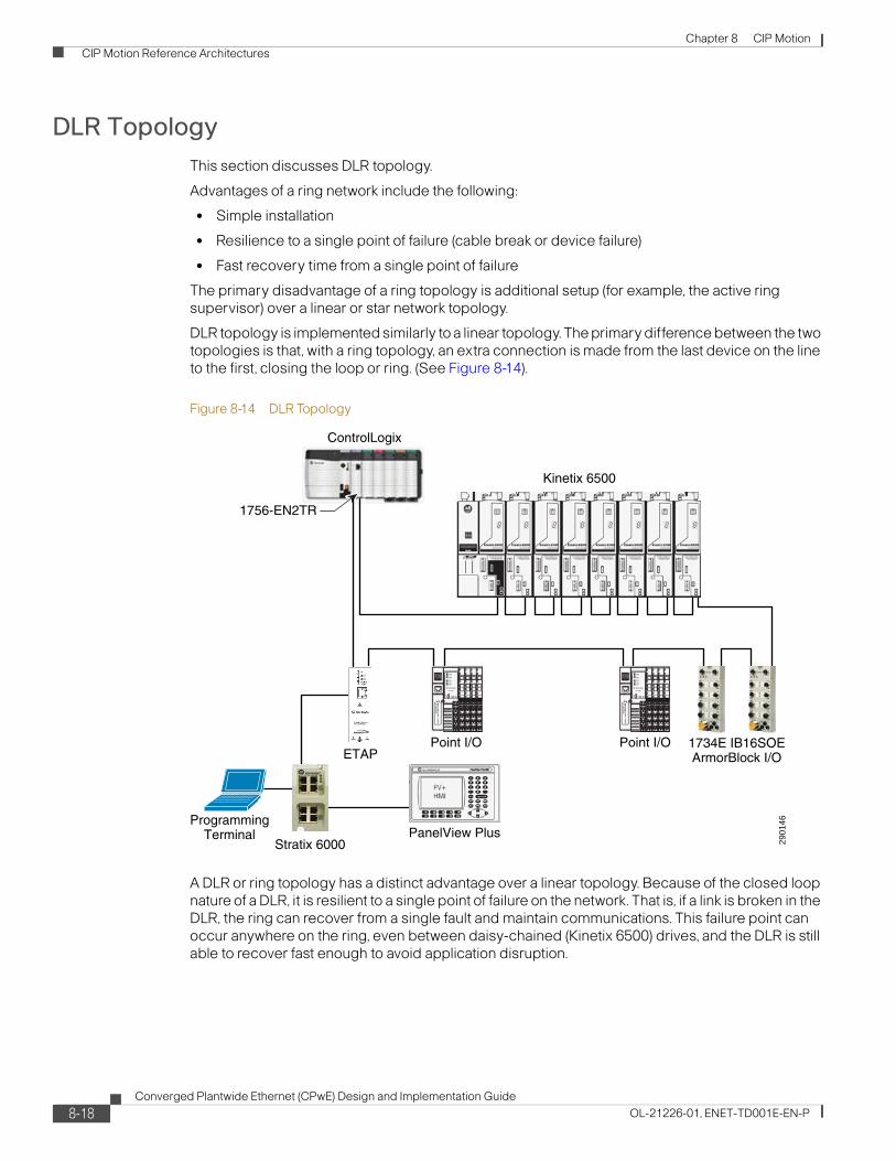
Chapter 8 CIP Motion CIP Motion Reference Architectures
DLR Topology This section discusses DLR topology.
Advantages of a ring network include the following:
• Simple installation
• Resilience to a single point of failure (cable break or device failure)
• Fast recovery time from a single point of failure
The primary disadvantage of a ring topology is additional setup (for example, the active ring supervisor) over a linear or star network topology.
DLR topology is implemented similarly to a linear topology. The primary difference between the two topologies is that, with a ring topology, an extra connection is made from the last device on the line to the first, closing the loop or ring. (See Figure 8-14).
Figure 8-14 DLR Topology
A DLR or ring topology has a distinct advantage over a linear topology. Because of the closed loop nature of a DLR, it is resilient to a single point of failure on the network. That is, if a link is broken in the DLR, the ring can recover from a single fault and maintain communications. This failure point can occur anywhere on the ring, even between daisy-chained (Kinetix 6500) drives, and the DLR is still able to recover fast enough to avoid application disruption.
2901
46
ControlLogix
1734E IB16SOEArmorBlock I/O
Kinetix 6500
Point I/OPoint I/O
1756-EN2TR
ProgrammingTerminal PanelView Plus
Stratix 6000
ETAP
8-18Converged Plantwide Ethernet (CPwE) Design and Implementation Guide
OL-21226-01, ENET-TD001E-EN-P
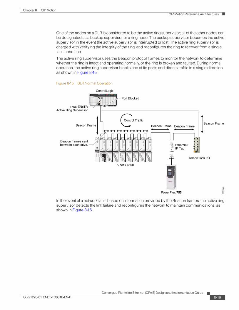
Chapter 8 CIP Motion CIP Motion Reference Architectures
One of the nodes on a DLR is considered to be the active ring supervisor; all of the other nodes can be designated as a backup supervisor or a ring node. The backup supervisor becomes the active supervisor in the event the active supervisor is interrupted or lost. The active ring supervisor is charged with verifying the integrity of the ring, and reconfigures the ring to recover from a single fault condition.
The active ring supervisor uses the Beacon protocol frames to monitor the network to determine whether the ring is intact and operating normally, or the ring is broken and faulted. During normal operation, the active ring supervisor blocks one of its ports and directs traffic in a single direction, as shown in Figure 8-15.
Figure 8-15 DLR Normal Operation
In the event of a network fault, based on information provided by the Beacon frames, the active ring supervisor detects the link failure and reconfigures the network to maintain communications, as shown in Figure 8-16.
2901
36
Kinetix 6500
ControlLogix
ArmorBlock I/O
Port Blocked
Beacon Frame Beacon Frame Beacon FrameBeacon Frame
Control Traffic
Beacon frames sentbetween each drive.
PowerFlex 755
EtherNet/IP Tap
1756-ENxTRActive Ring Supervisor
8-19Converged Plantwide Ethernet (CPwE) Design and Implementation Guide
OL-21226-01, ENET-TD001E-EN-P

Chapter 8 CIP Motion CIP Motion Reference Architectures
Figure 8-16 DLR Recovery After Link Failure
Following detection of the failure, the active ring supervisor begins passing network traffic through both of its ports by unblocking the previously blocked port. Recovery time for a DLR network is typically less than 3 ms for a 50-node network. Note that a DLR can recover only from a single point of failure.
Mixed Star/Ring Topology
Network switches can also be connected into a DLR via an EtherNet/IP tap, creating a star/ring topology, as shown in Figure 8-17.
2901
37
Kinetix 6500
ControlLogix
ArmorBlock I/O
Port Unblocked
Beacon Frame Link FailureBeacon Frame
Beacon FramePort 1
Control Traffic
Beacon frames sentbetween each drive.
PowerFlex 755
EtherNet/IP Tap
1756-ENxTRActive Ring Supervisor
Port 2Control Traffic
8-20Converged Plantwide Ethernet (CPwE) Design and Implementation Guide
OL-21226-01, ENET-TD001E-EN-P

Chapter 8 CIP Motion CIP Motion Reference Architectures
Figure 8-17 Star/Ring Topology—External Switch Connected into Ring via EtherNet/IP Tap
Devices that do not have embedded switch technology can be connected in a star topology off the switch. The DLR is able to retain all its inherent benefits, while allowing communication to occur between devices in the ring and devices connected in the star outside the ring.
DLR Topology Reference Architectures Under Test
The time-critical devices (for example, CIP Motion components, CIP Sync components, and I/O devices) are separated from the non-time-critical devices (for example, the PanelView programming terminal) in this architecture, as shown in Figure 8-18.
2901
38
Kinetix 6500
ControlLogix
PowerFlex 755
Point I/O
EtherNet/IP Tap
1756-ENxTR
ArmorBlock I/O
EtherNet/IP Tap
PanelView
PC
PowerFlex 40
Flex I/OStratix 6000
8-21Converged Plantwide Ethernet (CPwE) Design and Implementation Guide
OL-21226-01, ENET-TD001E-EN-P

Chapter 8 CIP Motion CIP Motion Reference Architectures
Figure 8-18 DLR Ring Reference Architecture
The time-critical components in this architecture are connected in the DLR. The ring supervisor of the DLR is the 1756-EN2TR module. If any single link in the DLR is lost, the ring re-converges in under 3 ms. The re-convergence time of the DLR ring is fast enough to allow all devices in the ring to operate without any interruptions. All the devices connected in the ring, including Kinetix 6500 Servo drives, continue operating during the temporary connection loss. This means that the DLR provides some resiliency for all the critical components in the architecture, such as Kinetix 6500 drives and I/O devices.
All the devices connected in the DLR must support at least two Ethernet ports. Any single-port device connected in the DLR must be connected to the switch from the 1783-ETAP module as shown in Figure 8-18. All two-port DLR devices support 1588 transparent clocks, as well as the Beacon ring protocol and QoS functionality. The transparent clock compensates for the packet transmission delay for each packet that goes through the device.
In the architecture shown in Figure 8-18, the grandmaster clock is the master clock in the system. All CIP Sync-enabled devices, such as Kinetix 6500 drives and 1732E-IB16SOE Armor Block I/O modules, synchronize their clocks to the grandmaster clock. The 1756-L6x/L7x controller and 1756-ENxT modules in the ControlLogix chassis, as shown in Figure 8-18, can be the grandmaster. By default, the 1756-EN2T or 1756-EN3T modules are the grandmaster when power is applied to the system.
The DLR ring architecture shown in Figure 8-18 contains the following components:
• Eight Kinetix 6500 drives
• Two CIP Sync-enabled 1734E-IB16SOE ArmorBlock I/O modules
• Two POINT I/O adapters
• Four 1783-ETAP modules
2901
46
ControlLogix
1734E IB16SOEArmorBlock I/O
Kinetix 6500
Point I/OPoint I/O
1756-EN2TR
ProgrammingTerminal PanelView Plus
Stratix 6000
ETAP
8-22Converged Plantwide Ethernet (CPwE) Design and Implementation Guide
OL-21226-01, ENET-TD001E-EN-P

Chapter 8 CIP Motion CIP Motion Reference Architectures
The 1783-ETAP modules connect to all the devices that have a single port, such as a programming terminal, Ixia Box traffic generator, and Panel View Plus terminal.
A Stratix 6000 or Stratix 8000 switch can be connected to the 1783-ETAP module, as shown in Figure 8-19 and Figure 8-20. The switches let you plug in many more Ethernet devices on the network without needing additional 1783-ETAP modules.
Note Although the Stratix 8000 supports the transparent clock functionality, it does not support the Beacon ring protocol; therefore, it is not recommended for use in the DLR.
Figure 8-19 DLR Ring Reference Architecture Connected to Stratix 8000 Switch
2901
45
ControlLogix
1734E IB16SOEArmorBlock I/O
Kinetix 6500
Point I/OPoint I/O
1756-EN2TR
ProgrammingTerminal
PanelView Plus
Stratix 8000 ETAP
8-23Converged Plantwide Ethernet (CPwE) Design and Implementation Guide
OL-21226-01, ENET-TD001E-EN-P

Chapter 8 CIP Motion CIP Motion Reference Architectures
Figure 8-20 DLR Ring Reference Architecture Connected to Stratix 6000 Switch
To test the architecture pictured above, the topology shown in Figure 8-21 was used.
Figure 8-21 DLR Ring Test Architecture
2901
46
ControlLogix
1734E IB16SOEArmorBlock I/O
Kinetix 6500
Point I/OPoint I/O
1756-EN2TR
ProgrammingTerminal PanelView Plus
Stratix 6000
ETAP
IXIA 2
2901
47
ControlLogix
1734E IB16SOEArmorBlock I/O
Kinetix 6500
Point I/O
PanelView Plus
1756-EN2TR
1756-EN2TR
ProgrammingTerminal
IXIA Box TrafficGenerator
Axis 0 Motor Shaft
Registration Input
Axis 0Test Standard
ETAP
ETAP
ETAP
ETAPIXIA 1
8-24Converged Plantwide Ethernet (CPwE) Design and Implementation Guide
OL-21226-01, ENET-TD001E-EN-P

Chapter 8 CIP Motion CIP Motion Reference Architectures
A reference drive (indicated as Axis 0) is used as the reference for all measurements. All measurements, as discussed in Test Criteria, page 8-29, are measured for this architecture.
The Ixia box is a network traffic generator device used to test this architecture. It generates both Class 1 and Class 3 traffic, as well as multicast and unicast traffic on the network. The configuration for the Ixia box is described in Ixia Network Traffic Generator Configuration, page 8-33.
Table 8-5 shows the system configuration parameters for testing this architecture.
Star TopologyThis section discusses various types of star topologies.
The star topology offers the advantage that if a point-to-point connection is lost to an end device, the rest of the network remains intact. The disadvantage of this approach is that all end devices must typically be connected back to a central location. This increases the amount of required cable infrastructure and increases the number of available ports required by the central switch, leading to a higher cost-per-node solution.
In a star network topology, all traffic that traverses the network (that is, device-to-device) must pass through the central switch, as shown in Figure 8-22.
Figure 8-22 Traditional Star Topology
Table 8-5 System Configuration Parameters
Controller coarse update rate (ms) 4
Number of CIP Motion axes 8
Number of rack-optimized I/O 2
Number of direct I/O 2
Rack-optimized I/O RPI (ms) 5
Direct I/O RPI (ms) 1
HMI PanelView Plus 1
1783-ETAP 4
2901
30
I/O
PC
Controller
HMI Drive
Switch
8-25Converged Plantwide Ethernet (CPwE) Design and Implementation Guide
OL-21226-01, ENET-TD001E-EN-P

Chapter 8 CIP Motion CIP Motion Reference Architectures
With the advent of devices containing EtherNet/IP embedded switch technology, alternative network topologies can now be achieved, covering a wide range of devices. Embedded switch technology places a multi-port switch directly into end devices, allowing not only for the traditional star, but also linear or ring network topologies. Embedded switch technology has been designed to support the features required by both CIP Sync and CIP Motion.
Star Topology Reference Architectures Under Test
All the components in the architecture are connected in a star topology to the Stratix 8000 Ethernet managed switch, as shown in Figure 8-23. The Stratix 8000 switch has 1588 time synchronization capabilities (transparent and boundary clock).
Figure 8-23 Star Reference Architecture
To test the architecture pictured above, the configuration shown in Figure 8-24 was used.
2901
42
ControlLogix
1734E IB16SOEArmorBlock I/O
Kinetix 6500
Point I/O
Stratix 8000
1756-EN2TR
ProgrammingTerminal
PowerFlex 40
PanelView Plus
8-26Converged Plantwide Ethernet (CPwE) Design and Implementation Guide
OL-21226-01, ENET-TD001E-EN-P

Chapter 8 CIP Motion CIP Motion Reference Architectures
Figure 8-24 Star Test Architecture
To test the star topology, a reference drive (indicated as Axis 0) is used as the reference for all measurements. All measurements, as discussed in Test Criteria, page 8-29, are measured for this architecture.
The Ixia box is a network traffic generator device used to test this architecture. It generates both Class 1 and Class 3 traffic, as well as multicast and unicast traffic on the network. The configuration for the Ixia box is described in Ixia Network Traffic Generator Configuration, page 8-33.
The Stratix 8000 switch is set up out of the box using Express Setup on the switch. See the documentation accompanying the switch for information on Express Setup.
Figure 8-25 shows the star topology test architecture.
2901
43
ControlLogix
1734E IB16SOEArmorBlock I/O
Kinetix 6500
Point I/O
Stratix 8000
1756-EN2TR
1756-EN2TR
ProgrammingTerminal
PowerFlex 40
IXIA Box TrafficGenerator
Axis 0 Motor Shaft
Registration Input
Axis 0Test StandardPanelView Plus
IXIA
1IX
IA 2
IXIA
3IX
IA 4
8-27Converged Plantwide Ethernet (CPwE) Design and Implementation Guide
OL-21226-01, ENET-TD001E-EN-P

Chapter 8 CIP Motion CIP Motion Reference Architecture Testing
Figure 8-25 Star Topology Test Architecture
The system configuration parameters for testing this architecture are shown in Table 8-6.
CIP Motion Reference Architecture TestingThe goals of the CIP Motion reference architecture testing were as follows:
• Characterize system performance of the CIP Motion system (using Kinetix 6500 drives, PowerFlex 755 drives, and CompactLogix L6x and L7x CIP Motion controllers)
• Validate network performance
• Provide recommended network architectures for Rockwell Automation customers using CIP Motion and CIP Sync
2901
44
ControlLogix
1734E IB16SOEArmorBlock I/O
Kinetix 6500
Point I/O
1756-EN2TR
ProgrammingTerminal
PanelView Plus
ETAP
ETAP
Table 8-6 System Configuration Parameters
Controller coarse update rate (ms) 4
Number of CIP Motion axes 8
Number of rack-optimized I/O 2
Number of direct I/O 2
Rack-optimized I/O RPI (ms) 5
Direct I/O RPI (ms) 1
HMI PanelView Plus 1
1783-ETAP 2
8-28Converged Plantwide Ethernet (CPwE) Design and Implementation Guide
OL-21226-01, ENET-TD001E-EN-P

Chapter 8 CIP Motion CIP Motion Reference Architecture Testing
Test CriteriaThe basic premise for CIP Motion control is that all devices on the network share a common, precise understanding of time. After time is established on the network, positioning information is sent to each relevant device along with the time that this positioning information is to be acted upon by the device.
To properly test a CIP Motion system, the infrastructure must be stressed in such a way as to attempt to compromise this functionality.
To measure the impact of this disruption in the system, the following three parameters were measured in the connected system:
• Offset to master
• Phase error
• Position error
The following sections give an overview of these parameters and how and why they are measured in the system.
Offset to Master
In any system where clock synchronization is accomplished, the local clock of a device powers up with an arbitrary value of time, as compared to system time. In this case, system time is defined as the absolute value of time delivered over the network by the CIP Sync (IEEE 1588) PTP. This value of time is normally referenced to a meaningful value of time as established against Coordinated Universal Time (UTC) time. When system time is delivered over the network, the difference between system time and the local clock time is calculated to create an offset value, referred to as Offset to Master, as shown in Figure 8-26. As each device continues to receive new references of time from the grandmaster, this offset value can change, depending on factors such as clock drift, or slight delays in delivery because of traffic or switch utilization.
Figure 8-26 Difference Between System Time and Local Time is the Offset to Master
Each CIP Motion device supports the CIP Sync time sync object. The time sync object supports the Offset to Master attribute. An explicit message instruction (MSG) with the configuration shown in Figure 8-27 is used to measure the Offset to Master value from each drive.
2901
49
_
_+
++
Clock
control
System Time
System Time
local
TimestampApplication
Offset toMaster
8-29Converged Plantwide Ethernet (CPwE) Design and Implementation Guide
OL-21226-01, ENET-TD001E-EN-P

Chapter 8 CIP Motion CIP Motion Reference Architecture Testing
Figure 8-27 Message Configuration for Time Sync Object—Offset to Master
In testing, the change in the Offset to Master value is plotted to reflect the stability of the system and indicate the general health of the time synchronization component of the system. This test is intended to validate the robustness of synchronization accuracy in the face of traffic and loading.
Phase Error
This measurement reflects the phase error between the motion planner and the axes. As the motion planner delivers time and position to the axes, this CIP Motion test measures the effect of data delivery delays because of the network infrastructure or traffic in system. Any delays through the network infrastructure are reflected as an offset or phase error between the actual position at the drive and the commanded position from the controller. It is important to note that this error is seen by all drives, so the drive-to-drive error is virtually zero if the drives share a common infrastructure.
Figure 8-28 illustrates a position phase error.
Figure 8-28 Position Phase Error
2901
51
Phase Error
8-30Converged Plantwide Ethernet (CPwE) Design and Implementation Guide
OL-21226-01, ENET-TD001E-EN-P

Chapter 8 CIP Motion CIP Motion Reference Architecture Testing
Figure 8-29 and Figure 8-30 show how this measurement is taken. A direct connection is established to a single axis, Axis 0, which is used as the standard for measuring the information coming from the motion planner. This connection goes directly from a dedicated EtherNet/IP module to the Axis 0 drive with no other network components introduced.
All other axes are driven through a network infrastructure. Traffic is injected into the network to introduce traffic loading.
Finally, a registration input is triggered once per revolution and driven into both the Axis 0 and Axis 1 drives. The difference in the respective latched positions reflects the phase error between the two devices. This position error is measured at a constant velocity. To normalize the data independently of velocity, the data is converted to time through the following equation:
PhaseErrorTime = (RegPosAxis0 – RegPosAxis1)/Velocity
Figure 8-29 Functional Test Arrangement for Phase Error Measurement
Figure 8-30 Hardware Test Arrangement for Phase Error Measurement
2901
52
_
+
Motion Planner
Motor/Feedback
Latched Position
Registration Latch
Command Position
Servo Drive
_
+ Motor/Feedback
Latched Position
Servo Drive
NetworkInfrastructure
2901
53
Kinetix 6500
ControlLogix
NetworkInfrastructure
Axis 0 Motor Shaft
Discrete WireEthernet Wire
Registration Input
Axis 0
Axis 1
1756-EN2TR
1756-EN2TR
8-31Converged Plantwide Ethernet (CPwE) Design and Implementation Guide
OL-21226-01, ENET-TD001E-EN-P

Chapter 8 CIP Motion CIP Motion Reference Architecture Testing
Position Error
This parameter measures position error from the position loop summing junction in the drive during constant velocity regulation. Because the drive receives position and time from the controller, any variation in position error during constant speed regulation is due strictly to clock variation. This parameter, then, measures position error in the drive at constant velocity to determine position error as a function of clock variations.
Figure 8-31 and Figure 8-32 show how this measurement is taken. A direct connection is established to a single axis, Axis 0, which is used as the standard for measuring the information coming from the motion planner. This connection goes directly from a dedicated EtherNet/IP module to the Axis 0 drive with no other network components introduced.
All other axes are driven through a network infrastructure. Traffic is injected into the network to introduce traffic loading.
At every controller motion planner update (coarse update rate), the position error from all the drives is captured. As in the previous measurement, position error is measured at a constant velocity. To normalize the data independently of velocity, the data is converted to time through the following equation:
Position Error = ((Position Error @ Axis)/ Velocity)
Figure 8-31 Position Error is Measured from the Position Loop Summing Junction in the Drive
Figure 8-32 Position Error is Captured Every Motion Planner Update
2901
54_
+
Motion Planner
Motor/FeedbackCommand Position
Position Error
Actual Position
Servo Drive29
0155
Kinetix 6500
ControlLogix
NetworkInfrastructure Ethernet Wire
Axis 0
Axis 1
1756-EN2TR
1756-EN2TR
8-32Converged Plantwide Ethernet (CPwE) Design and Implementation Guide
OL-21226-01, ENET-TD001E-EN-P

Chapter 8 CIP Motion CIP Motion Reference Architecture Testing
Ixia Network Traffic Generator Configuration
Two ports on the Ixia are used to generate different traffic patterns on the network.
The first port on the Ixia is connected directly to the Stratix 6000 or the Stratix 8000 switch on the network to generate traffic on the switch and stress the switch. This port is referred to as Ixia 3. The TCP/IP traffic stream simulates Layer 3 traffic (MES traffic). The traffic stream generated at Ixia 3 is received at port 4 of Ixia, referred to as Ixia 4.
The second port of the Ixia is connected in the ring or the linear segment, where all the automation components reside. This port is Ixia 2. The traffic stream generated at Ixia 2 is received at port 1 of the Ixia, (Ixia 1). The traffic streams passing through Ixia 1 and Ixia 2 stress the ring or the linear segment. This test is used to estimate the bandwidth capacity on the ring or linear segment.
Three traffic streams are used in the tests. The configuration of these traffic streams is shown in Table 8-7.
Test ResultsThis section outlines the results of the tests completed for the linear, star, and DLR architectures. These results summarize the tests for these topologies as configured in these test scenarios. The ultimate conclusion for each of these architectures is that the tested loading on each of these architectures has no impact on motion performance. See the results in the tables on the following pages.
Table 8-7 Traffic Stream Configuration
Traffic Pattern
Ixia Source Port
Ixia Destination Port Traffic Type Packet Size
Traffic Stream Rate
% of 100 Mbps Capacity
1 2 1 IPV4 TCP/IP—DSCP 58—Class 3 TCP Port 44818
1500 Bytes 700 pps 10%
1 2 IPV4 TCP/IP—DSCP 58—Class 3
2 Bytes 100 pps
2 2 1 IPV4 TCP/IP—DSCP 58—Class 3 TCP Port 4872
1500 Bytes 1400 pps 20%
1 2 IPV4 TCP/IP—DSCP 58—Class 3
2 Bytes 100 pps
3 2 1 IPV4 TCP/IP—DSCP 58—Class 3 TCP Port 4872
1500 Bytes 2800 pps 30%
1 2 IPV4 TCP/IP—DSCP 58—Class 3
2 Bytes 100 pps
4 2 1 IPV4 TCP/IP—DSCP 58—Class 3 TCP Port 4872
1500 Bytes 5600 pps 40%
1 2 IPV4 TCP/IP—DSCP 58—Class 3
2 Bytes 100 pps
5 2 1 IPV4 TCP/IP—DSCP 58—Class 3 TCP Port 4872
1500 Bytes 6000 pps 50%
1 2 IPV4 TCP/IP—DSCP 58—Class 3
2 Bytes 100 pps
6 2 1 IPV4 TCP/IP—DSCP 58—Class 3 TCP Port 4872
1500 Bytes 8000 pps 60%
1 2 IPV4 TCP/IP—DSCP 58—Class 3
2 Bytes 100 pps
8-33Converged Plantwide Ethernet (CPwE) Design and Implementation Guide
OL-21226-01, ENET-TD001E-EN-P

Chapter 8 CIP Motion CIP Motion Reference Architecture Testing
See these sections for illustrations of the test architectures:
• Basic Linear Topologies, page 8-11
• Linear topology can include many types of devices on the same network, as shown in Figure 8-8., page 8-12
• Star/Linear Topology, page 8-14
• Mixed Star/Ring Topology, page 8-20
See the “Detailed Test Results” section on page 8-40 for a full set of detailed test results.
Linear Architecture
All test parameters previously described were measured in these tests. All the results were measured with respect to the reference Kinetix 6500 drive (Axis 0). The drive is directly connected to the grandmaster clock. No Ixia traffic passes through this reference drive (Axis 0).
The test axis is the Kinetix 6500 drive under test. The Ixia traffic and other automation traffic pass through this drive (Axis 0).
The test traffic patterns are generated using the Ixia box. See the “Ixia Network Traffic Generator Configuration” section on page 8-33 for more details.
The following tests were performed:
• Test 1.1—Test @ nominal Ixia traffic load
• Test 1.2—Test @ 10% Ixia traffic load
• Test 1.3—Test @ 20% Ixia traffic load
• Test 1.4—Test @ 30% Ixia traffic load
• Test 1.5—Test @ 40% Ixia traffic load
• Test 1.6—Test @ 50% Ixia traffic load
Table 8-8 summarizes the test results.
Table 8-8 Linear Architecture Test Results
Test Case Test Criterion Results
Nominal loading Phase Error:
Position Error:
Offset to Master:
-3.15/2.02 μs
-1.85/1.79 μs
-1.93/2.02 μs
10% loading Phase Error:
Position Error:
Offset to Master:
-2.9/2.64 μs
-.1.96/1.96 μs
-1.97/2.04 μs
20% loading Phase Error:
Position Error:
Offset to Master:
-2.09/2.76 μs
-2.01/1.79 μs
-1.63/2.06 μs
30% loading Phase Error:
Position Error:
Offset to Master:
-2.09/2.49 μs
-2.01/2.07 μs
-1.89/1.93 μs
8-34Converged Plantwide Ethernet (CPwE) Design and Implementation Guide
OL-21226-01, ENET-TD001E-EN-P
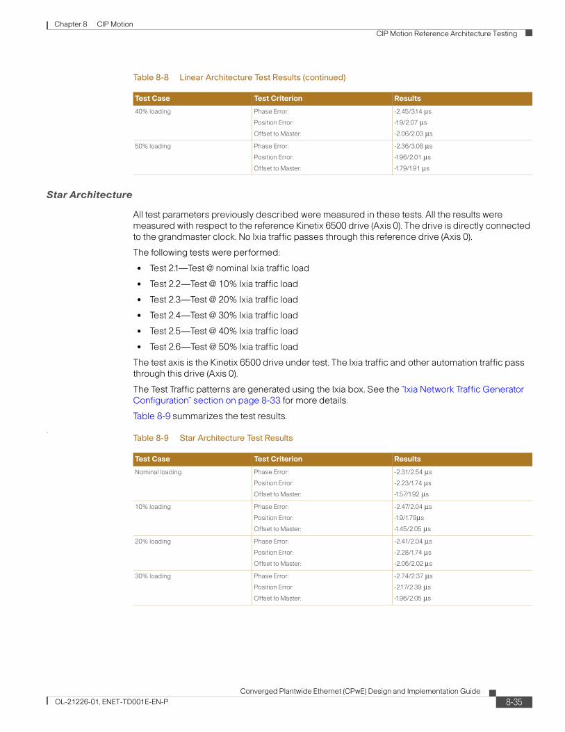
Chapter 8 CIP Motion CIP Motion Reference Architecture Testing
Star Architecture
All test parameters previously described were measured in these tests. All the results were measured with respect to the reference Kinetix 6500 drive (Axis 0). The drive is directly connected to the grandmaster clock. No Ixia traffic passes through this reference drive (Axis 0).
The following tests were performed:
• Test 2.1—Test @ nominal Ixia traffic load
• Test 2.2—Test @ 10% Ixia traffic load
• Test 2.3—Test @ 20% Ixia traffic load
• Test 2.4—Test @ 30% Ixia traffic load
• Test 2.5—Test @ 40% Ixia traffic load
• Test 2.6—Test @ 50% Ixia traffic load
The test axis is the Kinetix 6500 drive under test. The Ixia traffic and other automation traffic pass through this drive (Axis 0).
The Test Traffic patterns are generated using the Ixia box. See the “Ixia Network Traffic Generator Configuration” section on page 8-33 for more details.
Table 8-9 summarizes the test results.
.
40% loading Phase Error:
Position Error:
Offset to Master:
-2.45/3.14 μs
-1.9/2.07 μs
-2.06/2.03 μs
50% loading Phase Error:
Position Error:
Offset to Master:
-2.36/3.08 μs
-1.96/2.01 μs
-1.79/1.91 μs
Table 8-8 Linear Architecture Test Results (continued)
Test Case Test Criterion Results
Table 8-9 Star Architecture Test Results
Test Case Test Criterion Results
Nominal loading Phase Error:
Position Error:
Offset to Master:
-2.31/2.54 μs
-2.23/1.74 μs
-1.57/1.92 μs
10% loading Phase Error:
Position Error:
Offset to Master:
-2.47/2.04 μs
-1.9/1.79μs
-1.45/2.05 μs
20% loading Phase Error:
Position Error:
Offset to Master:
-2.41/2.04 μs
-2.28/1.74 μs
-2.06/2.02 μs
30% loading Phase Error:
Position Error:
Offset to Master:
-2.74/2.37 μs
-2.17/2.39 μs
-1.96/2.05 μs
8-35Converged Plantwide Ethernet (CPwE) Design and Implementation Guide
OL-21226-01, ENET-TD001E-EN-P

Chapter 8 CIP Motion CIP Motion Reference Architecture Testing
DLR Architecture
All test parameters previously described were measured in these tests. All the results were measured with respect to the reference Kinetix 6500 drive (Axis 0). The drive is directly connected to the grandmaster clock. No Ixia traffic passes through this reference drive (Axis 0).
The test axis is the Kinetix 6500 drive under test. The Ixia traffic and other automation traffic pass through this drive (Axis 0).
The test traffic patterns are generated using the Ixia box. See the “Ixia Network Traffic Generator Configuration” section on page 8-33 for more details.
The following tests were performed:
• Test 0.1—Test @ nominal Ixia traffic load
• Test 0.2—Test @ 10% Ixia traffic load
• Test 0.3—Test @ 20% Ixia traffic load
• Test 0.4—Test @ 30% Ixia traffic load
• Test 0.5—Test @ 40% Ixia traffic load
• Test 0.6—Test @ 50% Ixia traffic load
Table 8-10 summarizes the test results.
40% loading Phase Error:
Position Error:
Offset to Master:
-2.23/2.55 μs
-2.45/1.74 μs
-1.78/2.06 μs
50% loading Phase Error:
Position Error:
Offset to Master:
-2.5/2.35 μs
-2.23/1.85 μs
2.08/1.89 μs
Table 8-9 Star Architecture Test Results (continued)
Test Case Test Criterion Results
Table 8-10 DLR Architecture Test Results
Test Case Test Criterion Results
Nominal loading Phase Error:
Position Error:
Offset to Master:
-3/2.01 μs
-2.17/1.68 μs
-1.61/1.85 μs
10% loading Phase Error:
Position Error:
Offset to Master:
-2.84/2.17 μs
-2.28/1.96 μs
-1.75/1.97 μs
20% loading Phase Error:
Position Error:
Offset to Master:
-2.67/2.44 μs
-2.45/2.12 μs
-1.93/1.84 μs
30% loading Phase Error:
Position Error:
Offset to Master:
-3/2.4 μs
-2.17/1.96 μs
-1.7/1.99 μs
8-36Converged Plantwide Ethernet (CPwE) Design and Implementation Guide
OL-21226-01, ENET-TD001E-EN-P

Chapter 8 CIP Motion Design Recommendations
Design RecommendationsApplications that require high accuracy and performance, (for example, high performance motion control) should use devices that support time synchronization and that implement transparent clock or boundary clock mechanisms, such as the following:
• Stratix 8000 switches
• Kinetix 6500 drives
• ArmorBlock I/O
• 1783-ETAP module
• Point I/O
• 1756-ENT2R and 1756-ENT3R modules
• Embedded switch technology
– Includes transparent clock, Beacon ring protocol, QoS, and IGMP snooping functionality
– Used in all the devices listed above except the Stratix 8000 switches.
Applications that require less precision and accuracy (for example, general process time-stamping) may not require devices that support boundary or transparent clocks, but clock synchronization is not as accurate. If network components that do not support boundary or transparent clocks are selected, network loading must be kept to less than 20 percent and large packet sizes must be restricted.
These application types can be mixed only on the same subnet as long as those devices that require high precision have a clear view of the system time master via the mechanisms described above (that is, by using devices that maintain time accuracy through the use of transparent or boundary clocks.) This is easily managed in the architecture.
In CIP Motion applications, the use of transparent and boundary clocks, as well as QoS, makes the system extremely robust to variations in network loading.
In this guide, the motion control reference architectures tested were considered “high performance”. In this context, synchronization accuracies of ~ +2/- 2 μs were observed across the entire system, with phase error lags of +3/-3 μs and position error lags of ~ +2/-2 μs.
40% loading Phase Error:
Position Error:
Offset to Master:
-2.78/2.27 μs
-2.07/2.12 μs
-1.57/2.04 μs
50% loading Phase Error:
Position Error:
Offset to Master:
-2.56/2.38 μs
-2.07/1.74 μs
-1.53/2.09 μs
Table 8-10 DLR Architecture Test Results (continued)
Test Case Test Criterion Results
8-37Converged Plantwide Ethernet (CPwE) Design and Implementation Guide
OL-21226-01, ENET-TD001E-EN-P

Chapter 8 CIP Motion Design Recommendations
Time Accuracy as a Function of the ApplicationMotion control is one of many applications that require time synchronization in the control system. In addition to motion control, there are sequence-of-events applications where time stamping is required to determine the order in which certain events occurred. There are data logging applications that use time to associate when data was collected from the system, as well as scheduled-output applications, in which an output can be triggered based on time.
Each of these applications requires different levels of accuracy. Most data logging applications need little more than one-tenth of a second to a second of accuracy when logging data. Motion control, on the other hand, usually requires a much higher degree of synchronization; normally in microseconds ( μs) of accuracy.
The CIP Motion reference architectures that are shown in this guide are intended to support high precision motion control applications. It is possible to configure a motion control application with less stringent requirements with an Ethernet infrastructure that does not use time-correcting mechanisms such as transparent clocks and boundary clocks. If this is the case, a different configuration of devices could be incorporated, with less emphasis placed on those components.
To better understand the trade-offs in these applications, consider Table 8-11 and Figure 8-33, Figure 8-34, and Figure 8-35, which show phase error, position error, and Offset to Master when loading an unmanaged switch to 30 percent. In this situation, both phase error and position error were considerably degraded, compared to those architectures that used managed switches with time-compensating tools. In addition, this system could not be loaded beyond 30 percent without dramatically affecting system stability. While unmanaged switches can be used in these applications, care needs to be taken to ensure that traffic loading remains light and that packet sizes are small.
.
Figure 8-33 Phase Error for Unmanaged Switch Without Transparent or Boundary Clock, 30% Loading
Table 8-11 Unmanaged Switch Without Transparent or Boundary Clock
Test Case Attribute Test Result
30% loading Phase Error
Position Error
Offset to Master
+14/-11 μs
+8/-8 μs
+2.3/-2.3 μs
8-38Converged Plantwide Ethernet (CPwE) Design and Implementation Guide
OL-21226-01, ENET-TD001E-EN-P

Chapter 8 CIP Motion Design Recommendations
Figure 8-34 Position Error for Unmanaged Switch Without Transparent or Boundary Clock, 30% Loading
Figure 8-35 Offset to Master for Unmanaged Switch Without Transparent or Boundary clock, 30% Loading
8-39Converged Plantwide Ethernet (CPwE) Design and Implementation Guide
OL-21226-01, ENET-TD001E-EN-P

Chapter 8 CIP Motion Detailed Test Results
Detailed Test ResultsThe following is a summary of results for the tests described in this chapter.
Linear ArchitectureTable 8-12 and Figure 8-36 through Figure 8-53 summarize the results of the linear architecture test.
.Table 8-12 Linear Architecture Test Results
Test 1.1—Test @ Nominal Ixia Traffic Load
Test Procedure Step1Download the RefArchCIPMotion.acd program in the L7controller.
Step 2Toggle the Bit Start_Test to start the test.
Step 3Collect 100,000 samples.
Step 4Open the Excel spreadsheet DataHandling_V7_ArchTest_A8_Linear_BaseTraffic.xls
Step 5Click on Connect All Data Sheets to RSLinx Top (Logix Controller) button.
Step 6Click on Read All Data from Logix Controller button.
Step 7Wait for data to be read. Save the Excel file.
Results Summary Phase Error: -3.15/2.02 μs
Position Error: -1.85/1.79 μs
Offset: -1.93/2.02 μs
Test 1.2: Test @ 10 Ixia Traffic Load
Test Procedure Step1Download the RefArchCIPMotion.acd program in the L7controller.
Step 2Toggle the Bit Start_Test to start the test.
Step 3Collect 100,000 samples.
Step 4Open the Excel spreadsheet DataHandling_V7_ArchTest_A8_Linear_10%Traffic.xls
Step 5Click on Connect All Data Sheets to RSLinx Top (Logix Controller) button.
Step 6Click on Read All Data from Logix Controller button.
Step 7Wait for data to be read. Save the Excel file.
Results Summary Phase Error: -2.9/2.64 μs
Position Error: -.1.96/1.96 μs
Offset:-1.97/2.04 μs
Test 1.3: Test @ 20% Ixia Traffic Load
8-40Converged Plantwide Ethernet (CPwE) Design and Implementation Guide
OL-21226-01, ENET-TD001E-EN-P
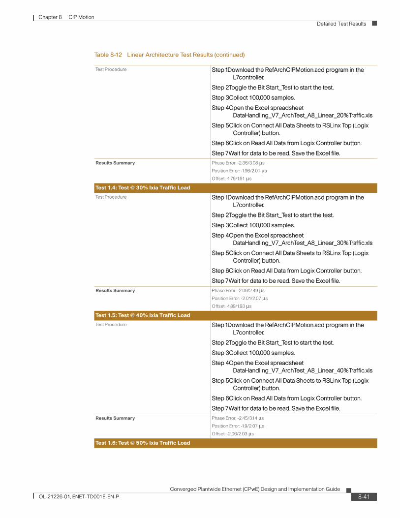
Chapter 8 CIP Motion Detailed Test Results
Test Procedure Step1Download the RefArchCIPMotion.acd program in the L7controller.
Step 2Toggle the Bit Start_Test to start the test.
Step 3Collect 100,000 samples.
Step 4Open the Excel spreadsheet DataHandling_V7_ArchTest_A8_Linear_20%Traffic.xls
Step 5Click on Connect All Data Sheets to RSLinx Top (Logix Controller) button.
Step 6Click on Read All Data from Logix Controller button.
Step 7Wait for data to be read. Save the Excel file.
Results Summary Phase Error: -2.36/3.08 μs
Position Error: -1.96/2.01 μs
Offset: -1.79/1.91 μs
Test 1.4: Test @ 30% Ixia Traffic Load
Test Procedure Step1Download the RefArchCIPMotion.acd program in the L7controller.
Step 2Toggle the Bit Start_Test to start the test.
Step 3Collect 100,000 samples.
Step 4Open the Excel spreadsheet DataHandling_V7_ArchTest_A8_Linear_30%Traffic.xls
Step 5Click on Connect All Data Sheets to RSLinx Top (Logix Controller) button.
Step 6Click on Read All Data from Logix Controller button.
Step 7Wait for data to be read. Save the Excel file.
Results Summary Phase Error: -2.09/2.49 μs
Position Error: -2.01/2.07 μs
Offset: -1.89/1.93 μs
Test 1.5: Test @ 40% Ixia Traffic Load
Test Procedure Step1Download the RefArchCIPMotion.acd program in the L7controller.
Step 2Toggle the Bit Start_Test to start the test.
Step 3Collect 100,000 samples.
Step 4Open the Excel spreadsheet DataHandling_V7_ArchTest_A8_Linear_40%Traffic.xls
Step 5Click on Connect All Data Sheets to RSLinx Top (Logix Controller) button.
Step 6Click on Read All Data from Logix Controller button.
Step 7Wait for data to be read. Save the Excel file.
Results Summary Phase Error: -2.45/3.14 μs
Position Error: -1.9/2.07 μs
Offset: -2.06/2.03 μs
Test 1.6: Test @ 50% Ixia Traffic Load
Table 8-12 Linear Architecture Test Results (continued)
8-41Converged Plantwide Ethernet (CPwE) Design and Implementation Guide
OL-21226-01, ENET-TD001E-EN-P

Chapter 8 CIP Motion Detailed Test Results
Figure 8-36 Linear Architecture Phase Error Test 1.1—Test @ Nominal Ixia Traffic Load
Figure 8-37 Linear Architecture Position Error Test 1.1—Test @ Nominal Ixia Traffic Load
Test Procedure Step1Download the RefArchCIPMotion.acd program in the L7controller.
Step 2Toggle the Bit Start_Test to start the test.
Step 3Collect 100,000 samples.
Step 4Open the Excel spreadsheet DataHandling_V7_ArchTest_A8_Linear_50%Traffic.xls
Step 5Click on Connect All Data Sheets to RSLinx Top (Logix Controller) button.
Step 6Click on Read All Data from Logix Controller button.
Step 7Wait for data to be read. Save the Excel file.
Results Summary Phase Error: -2.09/2.76 μs
Position Error: -2.01/1.79 μs
Offset: -1.63/2.06 μs
Table 8-12 Linear Architecture Test Results (continued)
2904
47
0
1000
2000
3000
4000
5000
6000
7000
8000
-10 -9 -8 -7 -6 -5 -4 -3 -2 -1 0 1 2 3 4 5 6 7 8 9 10
Phase Error (Time)min = -3.15 uSec max = 2.02 uSec
Time (Microseconds)
0
20
40
60
80
100
120
140
160
180
200
-10 -9 -8 -7 -6 -5 -4 -3 -2 -1 0 1 2 3 4 5 6 7 8 9 10
Position Error (Time) - Drive 2min = -1.852853 uSec max = 1.798357 uSec
Time (Microseconds)
2904
48
8-42Converged Plantwide Ethernet (CPwE) Design and Implementation Guide
OL-21226-01, ENET-TD001E-EN-P

Chapter 8 CIP Motion Detailed Test Results
Figure 8-38 Linear Architecture Offset to Master Test 1.1—Test @ Nominal Ixia Traffic Load
Figure 8-39 Linear Architecture Phase Error Test 1.2—Test @ 10% Ixia Traffic Load
0
20
40
60
80
100
120
140
160
180
200
-5000 -4000 -3000 -2000 -1000 0 1000 2000 3000 4000 5000
Offset to Master (Nanoseconds) - Drive 7min = -1930 nSec max = 2025 nSec
Time 2904
49
0
1000
2000
3000
4000
5000
6000
-10 -9 -8 -7 -6 -5 -4 -3 -2 -1 0 1 2 3 4 5 6 7 8 9 10
Phase Error (Time)min = -2.90 uSec max = 2.64 uSec
Time (Microseconds)
2904
50
8-43Converged Plantwide Ethernet (CPwE) Design and Implementation Guide
OL-21226-01, ENET-TD001E-EN-P

Chapter 8 CIP Motion Detailed Test Results
Figure 8-40 Linear Architecture Position Error Test 1.2—Test @ 10% Ixia Traffic Load
Figure 8-41 Linear Architecture Offset to Master Test 1.2—Test @ 10% Ixia Traffic Load
Figure 8-42 Linear Architecture Phase Error Test 1.3—Test @ 20% Ixia Traffic Load
0
20
40
60
80
100
120
140
160
180
200
-10 -9 -8 -7 -6 -5 -4 -3 -2 -1 0 1 2 3 4 5 6 7 8 9 10
Position Error (Time) - Drive 2min = -1.96 uSec max = 1.96 uSec
Time (Microseconds)
2904
51
0
20
40
60
80
100
120
140
160
180
200
-5000 -4000 -3000 -2000 -1000 0 1000 2000 3000 4000 5000
Offset to Master (Nanoseconds) - Drive 4min = -1970 nSec max = 2045 nSec
Time
2904
52
0
1000
2000
3000
4000
5000
6000
7000
-10 -9 -8 -7 -6 -5 -4 -3 -2 -1 0 1 2 3 4 5 6 7 8 9 10
Phase Error (Time)min = -2.09 uSec max = 2.76 uSec
Time (Microseconds)
2904
53
8-44Converged Plantwide Ethernet (CPwE) Design and Implementation Guide
OL-21226-01, ENET-TD001E-EN-P
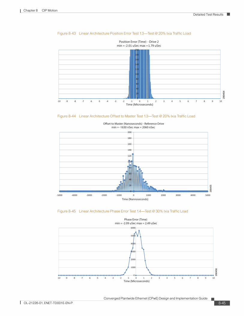
Chapter 8 CIP Motion Detailed Test Results
Figure 8-43 Linear Architecture Position Error Test 1.3—Test @ 20% Ixia Traffic Load
Figure 8-44 Linear Architecture Offset to Master Test 1.3—Test @ 20% Ixia Traffic Load
Figure 8-45 Linear Architecture Phase Error Test 1.4—Test @ 30% Ixia Traffic Load
0
20
40
60
80
100
120
140
160
180
200
-10 -9 -8 -7 -6 -5 -4 -3 -2 -1 0 1 2 3 4 5 6 7 8 9 10
Position Error (Time) - Drive 2min = -2.01 uSec max = 1.79 uSec
Time (Microseconds)
2904
54
0
20
40
60
80
100
120
140
160
180
200
-5000 -4000 -3000 -2000 -1000 0 1000 2000 3000 4000 5000
Offset to Master (Nanoseconds) - Reference Drivemin = -1630 nSec max = 2060 nSec
Time (Nannoseconds)
2904
55
0
1000
2000
3000
4000
5000
6000
-10 -9 -8 -7 -6 -5 -4 -3 -2 -1 0 1 2 3 4 5 6 7 8 9 10
Phase Error (Time)min = -2.09 uSec max = 2.49 uSec
Time (Microseconds)
2904
56
8-45Converged Plantwide Ethernet (CPwE) Design and Implementation Guide
OL-21226-01, ENET-TD001E-EN-P

Chapter 8 CIP Motion Detailed Test Results
Figure 8-46 Linear Architecture Position Error Test 1.4—Test @ 30% Ixia Traffic Load
Figure 8-47 Linear Architecture Offset to Master Test 1.4—Test @ 30% Ixia Traffic Load
Figure 8-48 Linear Architecture Phase Error Test 1.5—Test @ 40% Ixia Traffic Load
0
20
40
60
80
100
120
140
160
180
200
-10 -9 -8 -7 -6 -5 -4 -3 -2 -1 0 1 2 3 4 5 6 7 8 9 10
Position Error (Time) - Drive 2min = -2.01 uSec max = 2.07 uSec
Time (Microseconds)
2904
57
0
20
40
60
80
100
120
140
160
180
200
-5000 -4000 -3000 -2000 -1000 0 1000 2000 3000 4000 5000
Offset to Master (Nanoseconds) - Reference Drivemin = -1895 nSec max = 1935 nSec
Time (Nannoseconds)
2904
58
0
1000
2000
3000
4000
5000
6000
7000
-10 -9 -8 -7 -6 -5 -4 -3 -2 -1 0 1 2 3 4 5 6 7 8 9 10
Phase Error (Time)min = -2.45 uSec max = 3.14 uSec
Time (Microseconds)
2904
59
8-46Converged Plantwide Ethernet (CPwE) Design and Implementation Guide
OL-21226-01, ENET-TD001E-EN-P

Chapter 8 CIP Motion Detailed Test Results
Figure 8-49 Linear Architecture Position Error Test 1.5—Test @ 40% Ixia Traffic Load
Figure 8-50 Linear Architecture Offset to Master Test 1.5—Test @ 40% Ixia Traffic Load
Figure 8-51 Linear Architecture Phase Error Test 1.6—Test @ 50% Ixia Traffic Load
0
20
40
60
80
100
120
140
160
180
200
-10 -9 -8 -7 -6 -5 -4 -3 -2 -1 0 1 2 3 4 5 6 7 8 9 10
Position Error (Time) - Drive 2min = -1.90 uSec max = 2.07 uSec
Time (Microseconds)
2904
60
0
20
40
60
80
100
120
140
160
180
200
-5000 -4000 -3000 -2000 -1000 0 1000 2000 3000 4000 5000
Offset to Master (Nanoseconds) - Drive 2min = -2064 nSec max = 2035 nSec
Time (Nannoseconds)
2904
61
0
1000
2000
3000
4000
5000
6000
7000
8000
-10 -9 -8 -7 -6 -5 -4 -3 -2 -1 0 1 2 3 4 5 6 7 8 9 10
Phase Error (Time)min = -2.36 uSec max = 3.08 uSec
Time (Microseconds)
2904
62
8-47Converged Plantwide Ethernet (CPwE) Design and Implementation Guide
OL-21226-01, ENET-TD001E-EN-P

Chapter 8 CIP Motion Detailed Test Results
Figure 8-52 Linear Architecture Position Error Test 1.6—Test @ 50% Ixia Traffic Load
Figure 8-53 Linear Architecture Offset to Master Test 1.6—Test @ 50% Ixia Traffic Load
0
20
40
60
80
100
120
140
160
180
200
-10 -9 -8 -7 -6 -5 -4 -3 -2 -1 0 1 2 3 4 5 6 7 8 9 10
Position Error (Time) - Drive 2min = -1.96 uSec max = 2.01 uSec
Time (Microseconds)
2904
63
0
20
40
60
80
100
120
140
160
180
200
-5000 -4000 -3000 -2000 -1000 0 1000 2000 3000 4000 5000
Offset to Master (Nanoseconds) - Reference Drivemin = -1790 nSec max = 1910 nSec
Time (Nannoseconds)
2904
64
8-48Converged Plantwide Ethernet (CPwE) Design and Implementation Guide
OL-21226-01, ENET-TD001E-EN-P

Chapter 8 CIP Motion Detailed Test Results
Star ArchitectureTable 8-13 and Figure 8-54 through Figure 8-71 summarize the results of the star architecture test.
Table 8-13 Star Architecture Test Results
Test 2.1 @ Test Nominal IX Traffic Load
Test Procedure Step1Download the RefArchCIPMotion.acd program in the L75controller.
Step 2Toggle the Bit Start_Test to start the test.
Step 3Collect 100,000 samples.
Step 4Open the Excel spreadsheet DataHandling_V7_ArchTest_A8_Linear_BaseTraffic.xls
Step 5Click on Connect All Data Sheets to RSLinx Top (Logix Controller) button.
Step 6Click on Read All Data from Logix Controller button.
Step 7Wait for data to be read. Save the Excel file.
Results Summary Phase Error: -2.31/2.54 μs
Position Error: -2.23/1.74 μs
Offset: -1.57/1.92 μs
Test 2.2: Test @ 10% Ixia Traffic Load
Test Procedure Step1Download the RefArchCIPMotion.acd program in the L75controller.
Step 2Toggle the Bit Start_Test to start the test.
Step 3Collect 100,000 samples.
Step 4Open the Excel spreadsheet DataHandling_V7_ArchTest_A8_Linear_BaseTraffic.xls
Step 5Click on Connect All Data Sheets to RSLinx Top (Logix Controller) button.
Step 6Click on Read All Data from Logix Controller button.
Step 7Wait for data to be read. Save the Excel file.
Results Summary Phase Error: -2.47/2.04 μs
Position Error: -1.9/1.79μs
Offset: -1.45/2.05 μs
Test 2-3: Test @ 20% Ixia Traffic Load
8-49Converged Plantwide Ethernet (CPwE) Design and Implementation Guide
OL-21226-01, ENET-TD001E-EN-P

Chapter 8 CIP Motion Detailed Test Results
Test Procedure Step1Download the RefArchCIPMotion.acd program in the L75controller.
Step 2Toggle the Bit Start_Test to start the test.
Step 3Collect 100,000 samples.
Step 4Open the Excel spreadsheet DataHandling_V7_ArchTest_A8_Linear_BaseTraffic.xls
Step 5Click on Connect All Data Sheets to RSLinx Top (Logix Controller) button.
Step 6Click on Read All Data from Logix Controller button.
Step 7Wait for data to be read. Save the Excel file.
Results Summary Phase Error: -2.41/2.04 μs
Position Error: -2.28/1.74 μs
Offset: -2.06/2.02 μs
Test 2.4: Test @ 30% Ixia Traffic Load
Test Procedure Step1Download the RefArchCIPMotion.acd program in the L75controller.
Step 2Toggle the Bit Start_Test to start the test.
Step 3Collect 100,000 samples.
Step 4Open the Excel spreadsheet DataHandling_V7_ArchTest_A8_Linear_BaseTraffic.xls
Step 5Click on Connect All Data Sheets to RSLinx Top (Logix Controller) button.
Step 6Click on Read All Data from Logix Controller button.
Step 7Wait for data to be read. Save the Excel file.
Results Summary Phase Error: -2.09/2.49 μs
Position Error: -2.01/2.07 μs
Offset: -1.89/1.93 μs
Test 2.5: Test @ 40% Ixia Traffic Load
Test Procedure Step1Download the RefArchCIPMotion.acd program in the L75controller.
Step 2Toggle the Bit Start_Test to start the test.
Step 3Collect 100,000 samples.
Step 4Open the Excel spreadsheet DataHandling_V7_ArchTest_A8_Linear_BaseTraffic.xls
Step 5Click on Connect All Data Sheets to RSLinx Top (Logix Controller) button.
Step 6Click on Read All Data from Logix Controller button.
Step 7Wait for data to be read. Save the Excel file.
Table 8-13 Star Architecture Test Results (continued)
8-50Converged Plantwide Ethernet (CPwE) Design and Implementation Guide
OL-21226-01, ENET-TD001E-EN-P

Chapter 8 CIP Motion Detailed Test Results
Figure 8-54 Star Architecture Phase Error Test 2.1—Test @ Nominal Ixia Traffic Load
Results Summary Phase Error: -2.23/2.55 μs
Position Error: -2.45/1.74 μs
Offset: -1.78/2.06 μs
Test 2.6: Test @ 50% Ixia Traffic Load
Test Procedure Step1Download the RefArchCIPMotion.acd program in the L75controller.
Step 2Toggle the Bit Start_Test to start the test.
Step 3Collect 100,000 samples.
Step 4Open the Excel spreadsheet DataHandling_V7_ArchTest_A8_Linear_BaseTraffic.xls
Step 5Click on Connect All Data Sheets to RSLinx Top (Logix Controller) button.
Step 6Click on Read All Data from Logix Controller button.
Step 7Wait for data to be read. Save the Excel file.
Results Summary Phase Error: -2.5/2.35 μs
Position Error: -2.23/1.85 μs
Offset: 2.08/1.89 μs
Table 8-13 Star Architecture Test Results (continued)
0
1000
2000
3000
4000
5000
6000
7000
-10 -9 -8 -7 -6 -5 -4 -3 -2 -1 0 1 2 3 4 5 6 7 8 9 10
Phase Error (Time)min = -2.31 uSec max = 2.54 uSec
Time (Microseconds)29
0465
8-51Converged Plantwide Ethernet (CPwE) Design and Implementation Guide
OL-21226-01, ENET-TD001E-EN-P

Chapter 8 CIP Motion Detailed Test Results
Figure 8-55 Star Architecture Position Error Test 2.1—Test @ Nominal Ixia Traffic Load
Figure 8-56 Star Architecture Offset to Master Test 2.1—Test @ Nominal Ixia Traffic Load
Figure 8-57 Star Architecture Phase Error Test 2.2—Test @ 10% Ixia Traffic Load
0
20
40
60
80
100
120
140
160
180
200
-10 -9 -8 -7 -6 -5 -4 -3 -2 -1 0 1 2 3 4 5 6 7 8 9 10
Position Error (Time) - Drive 2min = -2.23 uSec max = 1.74 uSec
Time (Microseconds)
2904
66
0
20
40
60
80
100
120
140
160
180
200
-5000 -4000 -3000 -2000 -1000 0 1000 2000 3000 4000 5000
Offset to Master (Nanoseconds) - Drive 7min = -1570 nSec max = 1920 nSec
Time
2904
67
0
1000
2000
3000
4000
5000
6000
7000
8000
-10 -9 -8 -7 -6 -5 -4 -3 -2 -1 0 1 2 3 4 5 6 7 8 9 10
Phase Error (Time)min = -2.47 uSec max = 2.04 uSec
Time (Microseconds)
2904
68
8-52Converged Plantwide Ethernet (CPwE) Design and Implementation Guide
OL-21226-01, ENET-TD001E-EN-P

Chapter 8 CIP Motion Detailed Test Results
0
1000
2000
3000
4000
5000
6000
7000
-10 -9 -8 -7 -6 -5 -4 -3 -2 -1 0 1 2 3 4 5 6 7 8 9 10
2904
74
Phase Error (Time)min = -2.74 uSec max = 2.37 uSec
Time (Microseconds)
Figure 8-58 Star Architecture Position Error Test 2.2—Test @ 10% Ixia Traffic Load
Figure 8-59 Star Architecture Offset to Master Test 2.2—Test @ 10% Ixia Traffic Load
Figure 8-60 Star Architecture Phase Error Test 23—Test @ 20% IX.IA Traffic Load
0
20
40
60
80
100
120
140
160
180
200
-10 -9 -8 -7 -6 -5 -4 -3 -2 -1 0 1 2 3 4 5 6 7 8 9 10
Position Error (Time) - Drive 2min = -1.907349 uSec max = 1.798357 uSec
Time (Microseconds)
2904
69
0
20
40
60
80
100
120
140
160
180
200
-5000 -4000 -3000 -2000 -1000 0 1000 2000 3000 4000 5000
Offset to Master (Nanoseconds) - Drive 7min = -1450 nSec max = 2050 nSec
Time
2904
70
0
1000
2000
3000
4000
5000
6000
7000
-10 -9 -8 -7 -6 -5 -4 -3 -2 -1 0 1 2 3 4 5 6 7 8 9 10
Phase Error (Time)min = -2.41 uSec max = 2.04 uSec
Time (Microseconds)
2904
71
8-53Converged Plantwide Ethernet (CPwE) Design and Implementation Guide
OL-21226-01, ENET-TD001E-EN-P

Chapter 8 CIP Motion Detailed Test Results
Figure 8-61 Star Architecture Position Error Test 2.3—Test @ 20% Ixia Traffic Load
Figure 8-62 Star Architecture Offset to Master Test 2.3—Test @ 20% Ixia Traffic Load
Figure 8-63 Star Architecture Phase Error Test 2.4—Test @ 30% Ixia Traffic Load
0
20
40
60
80
100
120
140
160
180
200
-10 -9 -8 -7 -6 -5 -4 -3 -2 -1 0 1 2 3 4 5 6 7 8 9 10
Position Error (Time) - Drive 2min = -2.28 uSec max = 1.74 uSec
Time (Microseconds)
2904
72
0
20
40
60
80
100
120
140
160
180
200
-5000 -4000 -3000 -2000 -1000 0 1000 2000 3000 4000 5000
Offset to Master (Nanoseconds) - Drive 6min = -2065 nSec max = 2020 nSec
Time 29
0473
0
1000
2000
3000
4000
5000
6000
7000
-10 -9 -8 -7 -6 -5 -4 -3 -2 -1 0 1 2 3 4 5 6 7 8 9 10
2904
74
Phase Error (Time)min = -2.74 uSec max = 2.37 uSec
Time (Microseconds)
8-54Converged Plantwide Ethernet (CPwE) Design and Implementation Guide
OL-21226-01, ENET-TD001E-EN-P

Chapter 8 CIP Motion Detailed Test Results
Figure 8-64 Star Architecture Position Error Test 2.4—Test @ 30% Ixia Traffic Load
Figure 8-65 Star Architecture Offset to Master Test 2.4—Test @ 30% Ixia Traffic Load
Figure 8-66 Star Architecture Phase Error Test 2.5—Test @ 40% Ixia Traffic Load
0
20
40
60
80
100
120
140
160
180
200
-10 -9 -8 -7 -6 -5 -4 -3 -2 -1 0 1 2 3 4 5 6 7 8 9 10
Position Error (Time) - Drive 2min = -2.17 uSec max = 2.39 uSec
Time (Microseconds)
2904
75
0
20
40
60
80
100
120
140
160
180
200
-5000 -4000 -3000 -2000 -1000 0 1000 2000 3000 4000 5000
Offset to Master (Nanoseconds) - Drive 5min = -1960 nSec max = 2050 nSec
Time
2904
76
0
1000
2000
3000
4000
5000
6000
7000
-10 -9 -8 -7 -6 -5 -4 -3 -2 -1 0 1 2 3 4 5 6 7 8 9 10
Phase Error (Time)min = -2.23 uSec max = 2.55 uSec
Time (Microseconds)
2904
77
8-55Converged Plantwide Ethernet (CPwE) Design and Implementation Guide
OL-21226-01, ENET-TD001E-EN-P
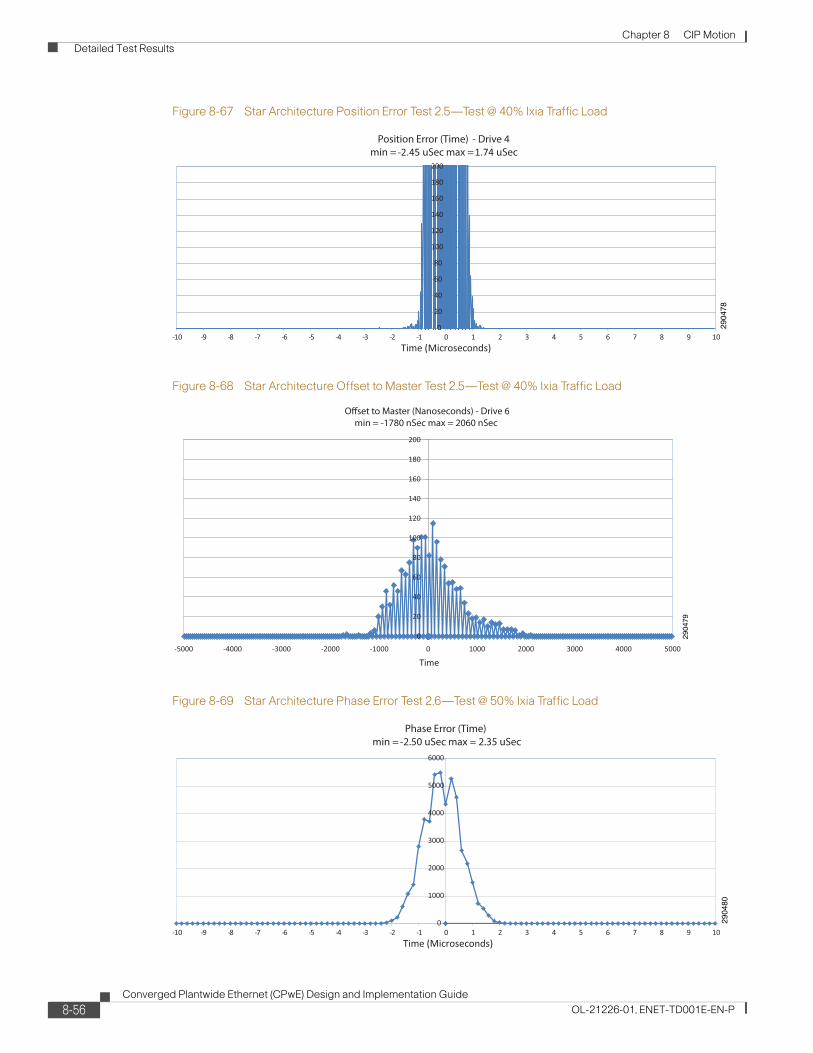
Chapter 8 CIP Motion Detailed Test Results
Figure 8-67 Star Architecture Position Error Test 2.5—Test @ 40% Ixia Traffic Load
Figure 8-68 Star Architecture Offset to Master Test 2.5—Test @ 40% Ixia Traffic Load
Figure 8-69 Star Architecture Phase Error Test 2.6—Test @ 50% Ixia Traffic Load
0
20
40
60
80
100
120
140
160
180
200
-10 -9 -8 -7 -6 -5 -4 -3 -2 -1 0 1 2 3 4 5 6 7 8 9 10
Position Error (Time) - Drive 4min = -2.45 uSec max = 1.74 uSec
Time (Microseconds)
2904
78
0
20
40
60
80
100
120
140
160
180
200
-5000 -4000 -3000 -2000 -1000 0 1000 2000 3000 4000 5000
Offset to Master (Nanoseconds) - Drive 6min = -1780 nSec max = 2060 nSec
Time
2904
79
0
1000
2000
3000
4000
5000
6000
-10 -9 -8 -7 -6 -5 -4 -3 -2 -1 0 1 2 3 4 5 6 7 8 9 10
Phase Error (Time)min = -2.50 uSec max = 2.35 uSec
Time (Microseconds)
2904
80
8-56Converged Plantwide Ethernet (CPwE) Design and Implementation Guide
OL-21226-01, ENET-TD001E-EN-P

Chapter 8 CIP Motion Detailed Test Results
Figure 8-70 Star Architecture Position Error Test 2.6—Test @ 50% Ixia Traffic Load
Figure 8-71 Star Architecture Offset to Master Test 2.6—Test @ 50% Ixia Traffic Load
Device-Level Ring (DLR) ArchitectureTable 8-14 and Figure 8-72 through Figure 8-89 summarize the results of the DLR architecture test.
0
20
40
60
80
100
120
140
160
180
200
-10 -9 -8 -7 -6 -5 -4 -3 -2 -1 0 1 2 3 4 5 6 7 8 9 10
Position Error (Time) - Drive 2min = -2.23uSec max = 1.85uSec
Time (Microseconds)
2904
81
0
20
40
60
80
100
120
140
160
180
200
-5000 -4000 -3000 -2000 -1000 0 1000 2000 3000 4000 5000
Offset to Master (Nanoseconds) - Reference Drivemin = -2085 nSec max = 1890 nSec
Time (Nannoseconds)
2904
82
8-57Converged Plantwide Ethernet (CPwE) Design and Implementation Guide
OL-21226-01, ENET-TD001E-EN-P

Chapter 8 CIP Motion Detailed Test Results
Table 8-14 DLR Architecture Test Results
Test 0.1: Test @ Nominal Ixia Traffic Load
Test Procedure Step1Download the RefArchCIPMotion.acd program in the L7controller.
Step 2Toggle the Bit Start_Test to start the test.
Step 3Collect 100,000 samples.
Step 4Open the Excel spreadsheet DataHandling_V7_ArchTest_A8_Linear_BaseTraffic.xls
Step 5Click on Connect All Data Sheets to RSLinx Top (Logix Controller) button.
Step 6Click on Read All Data from Logix Controller button.
Step 7Wait for data to be read. Save the Excel file.
Results Summary Phase Error: -3/2.01 μs
Position Error: -2.17/1.68 μs
Offset: -1.61/1.85 μs
Test 0.2: Test @ 10 Ixia Traffic Load
Test Procedure Step1Download the RefArchCIPMotion.acd program in the L7controller.
Step 2Toggle the Bit Start_Test to start the test.
Step 3Collect 100,000 samples.
Step 4Open the Excel spreadsheet DataHandling_V7_ArchTest_A8_Linear_10%Traffic.xls
Step 5Click on Connect All Data Sheets to RSLinx Top (Logix Controller) button.
Step 6Click on Read All Data from Logix Controller button.
Step 7Wait for data to be read. Save the Excel file.
Results Summary Phase Error: -2.84/2.17 μs
Position Error: -2.28/1.96 μs
Offset: -1.75/1.97 μs
Test 0.3: Test @ 20 Ixia Traffic Load
8-58Converged Plantwide Ethernet (CPwE) Design and Implementation Guide
OL-21226-01, ENET-TD001E-EN-P

Chapter 8 CIP Motion Detailed Test Results
Test Procedure Step1Download the RefArchCIPMotion.acd program in the L7controller.
Step 2Toggle the Bit Start_Test to start the test.
Step 3Collect 100,000 samples.
Step 4Open the Excel spreadsheet DataHandling_V7_ArchTest_A8_Linear_20%Traffic.xls
Step 5Click on Connect All Data Sheets to RSLinx Top (Logix Controller) button.
Step 6Click on Read All Data from Logix Controller button.
Step 7Wait for data to be read. Save the Excel file.
Results Summary Phase Error: -2.67/2.44 μs
Position Error: -2.45/2.12 μs
Offset: -1.93/1.84 μs
Test 0.4: Test @ 30% Ixia Traffic Load
Test Procedure Step1Download the RefArchCIPMotion.acd program in the L7controller.
Step 2Toggle the Bit Start_Test to start the test.
Step 3Collect 100,000 samples.
Step 4Open the Excel spreadsheet DataHandling_V7_ArchTest_A8_Linear_30%Traffic.xls
Step 5Click on Connect All Data Sheets to RSLinx Top (Logix Controller) button.
Step 6Click on Read All Data from Logix Controller button.
Step 7Wait for data to be read. Save the Excel file.
Results Summary Phase Error: -3/2.4 μs
Position Error: -2.17/1.96 μs
Offset: -1.7/1.99 μs
Test 0.5: Test @ 40% Ixia Traffic Load
Test Procedure Step1Download the RefArchCIPMotion.acd program in the L7controller.
Step 2Toggle the Bit Start_Test to start the test.
Step 3Collect 100,000 samples.
Step 4Open the Excel spreadsheet DataHandling_V7_ArchTest_A8_Linear_40%Traffic.xls
Step 5Click on Connect All Data Sheets to RSLinx Top (Logix Controller) button.
Step 6Click on Read All Data from Logix Controller button.
Step 7Wait for data to be read. Save the Excel file.
Table 8-14 DLR Architecture Test Results (continued)
8-59Converged Plantwide Ethernet (CPwE) Design and Implementation Guide
OL-21226-01, ENET-TD001E-EN-P

Chapter 8 CIP Motion Detailed Test Results
Figure 8-72 DLR Architecture Phase Error Test 0.1—Test @ Nominal Ixia Traffic Load
Results Summary Phase Error: -2.78/2.27 μs
Position Error: -2.07/2.12 μs
Offset: -1.57/2.04 μs
Test 0.6: Test @ 50% Ixia Traffic Load
Test Procedure Step1Download the RefArchCIPMotion.acd program in the L7controller.
Step 2Toggle the Bit Start_Test to start the test.
Step 3Collect 100,000 samples.
Step 4Open the Excel spreadsheet DataHandling_V7_ArchTest_A8_Linear_50%Traffic.xls
Step 5Click on Connect All Data Sheets to RSLinx Top (Logix Controller) button.
Step 6Click on Read All Data from Logix Controller button.
Step 7Wait for data to be read. Save the Excel file.
Results Summary Phase Error: -2.56/2.38 μs
Position Error: -2.07/1.74 μs
Offset: -1.53/2.09 μs
Table 8-14 DLR Architecture Test Results (continued)
0
1000
2000
3000
4000
5000
6000
-10 -9 -8 -7 -6 -5 -4 -3 -2 -1 0 1 2 3 4 5 6 7 8 9 10
Phase Error (Time)min = -3.00 uSec max = 2.01 uSec
Time (Microseconds)
2904
83
8-60Converged Plantwide Ethernet (CPwE) Design and Implementation Guide
OL-21226-01, ENET-TD001E-EN-P

Chapter 8 CIP Motion Detailed Test Results
Figure 8-73 DLR Architecture Position Error Test 0.1—Test @ Nominal Ixia Traffic Load
Figure 8-74 DLR Architecture Offset to Master Test 0.1—Test @ Nominal Ixia Traffic Load
Figure 8-75 DLR Architecture Phase Error Test 0.2—Test @ 10% Ixia Traffic Load
0
20
40
60
80
100
120
140
160
180
200
-10 -9 -8 -7 -6 -5 -4 -3 -2 -1 0 1 2 3 4 5 6 7 8 9 10
Position Error (Time) - Drive 6min = -2.179827 uSec max = 1.689366 uSec
Time (Microseconds)
2904
84
0
20
40
60
80
100
120
140
160
180
200
-5000 -4000 -3000 -2000 -1000 0 1000 2000 3000 4000 5000
Offset to Master (Nanoseconds) - Drive 2min = -1610 nSec max = 1850 nSec
Time (Nannoseconds)
2904
85
0
1000
2000
3000
4000
5000
6000
7000
8000
-10 -9 -8 -7 -6 -5 -4 -3 -2 -1 0 1 2 3 4 5 6 7 8 9 10
Phase Error (Time)min = -2.84 uSec max = 2.17 uSec
Time (Microseconds)
2904
86
8-61Converged Plantwide Ethernet (CPwE) Design and Implementation Guide
OL-21226-01, ENET-TD001E-EN-P

Chapter 8 CIP Motion Detailed Test Results
Figure 8-76 DLR Architecture Position Error Test 0.2—Test @ 10% Ixia Traffic Load
Figure 8-77 DLR Architecture Offset to Master Test 0.2—Test @ 10% Ixia Traffic Load
Figure 8-78 DLR Architecture Phase Error Test 0.3—Test @ 20% IX.IA Traffic Load
0
20
40
60
80
100
120
140
160
180
200
-10 -9 -8 -7 -6 -5 -4 -3 -2 -1 0 1 2 3 4 5 6 7 8 9 10
Position Error (Time) - Drive 6min = -2.28 uSec max = 1.96 uSec
Time (Microseconds)
2904
87
0
20
40
60
80
100
120
140
160
180
200
-5000 -4000 -3000 -2000 -1000 0 1000 2000 3000 4000 5000
Offset to Master (Nanoseconds) - Reference Drivemin = -1755 nSec max = 1974 nSec
Time (Nannoseconds)
2904
88
0
1000
2000
3000
4000
5000
6000
7000
-10 -9 -8 -7 -6 -5 -4 -3 -2 -1 0 1 2 3 4 5 6 7 8 9 10
Phase Error (Time)min = -2.67 uSec max = 2.44 uSec
Time (Microseconds)
2904
89
8-62Converged Plantwide Ethernet (CPwE) Design and Implementation Guide
OL-21226-01, ENET-TD001E-EN-P

Chapter 8 CIP Motion Detailed Test Results
Figure 8-79 DLR Architecture Position Error Test 0.3—Test @ 20% Ixia Traffic Load
Figure 8-80 DLR Architecture Offset to Master Test 0.3—Test @ 20% Ixia Traffic Load
Figure 8-81 DLR Architecture Phase Error Test 0.4—Test @ 30% Ixia Traffic Load
0
20
40
60
80
100
120
140
160
180
200
-10 -9 -8 -7 -6 -5 -4 -3 -2 -1 0 1 2 3 4 5 6 7 8 9 10
Position Error (Time) - Drive 2min = -2.45uSec max = 2.12uSec
Time (Microseconds)
2904
90
0
20
40
60
80
100
120
140
160
180
200
-5000 -4000 -3000 -2000 -1000 0 1000 2000 3000 4000 5000
Offset to Master (Nanoseconds) - Drive 3min = -1930 nSec max = 1845 nSec
Time
2904
91
0
1000
2000
3000
4000
5000
6000
7000
-10 -9 -8 -7 -6 -5 -4 -3 -2 -1 0 1 2 3 4 5 6 7 8 9 10
Phase Error (Time)min = -3.00 uSec max = 2.40 uSec
Time (Microseconds)
2904
92
8-63Converged Plantwide Ethernet (CPwE) Design and Implementation Guide
OL-21226-01, ENET-TD001E-EN-P

Chapter 8 CIP Motion Detailed Test Results
Figure 8-82 DLR Architecture Position Error Test 0.4—Test @ 30% Ixia Traffic Load
Figure 8-83 DLR Architecture Offset to Master Test 0.4—Test @ 30% Ixia Traffic Load
Figure 8-84 DLR Architecture Phase Error Test 0.5—Test @ 40% Ixia Traffic Load
0
20
40
60
80
100
120
140
160
180
200
-10 -9 -8 -7 -6 -5 -4 -3 -2 -1 0 1 2 3 4 5 6 7 8 9 10
Position Error (Time) - Drive 1min = -2.17 uSec max = 1.96 uSec
Time (Microseconds)
2904
93
0
20
40
60
80
100
120
140
160
180
200
-5000 -4000 -3000 -2000 -1000 0 1000 2000 3000 4000 5000
Offset to Master (Nanoseconds) - Drive 5min = -1700 nSec max = 1995 nSec
Time
2904
94
0
1000
2000
3000
4000
5000
6000
7000
-10 -9 -8 -7 -6 -5 -4 -3 -2 -1 0 1 2 3 4 5 6 7 8 9 10
2904
95
Phase Error (Time)min = -2.78 uSec max = 2.27 uSec
Time (Microseconds)
8-64Converged Plantwide Ethernet (CPwE) Design and Implementation Guide
OL-21226-01, ENET-TD001E-EN-P

Chapter 8 CIP Motion Detailed Test Results
Figure 8-85 DLR Architecture Position Error Test 0.5—Test @ 40% Ixia Traffic Load
Figure 8-86 DLR Architecture Offset to Master Test 0.5—Test @ 40% Ixia Traffic Load
Figure 8-87 DLR Architecture Phase Error Test 0.6—Test @ 50% Ixia Traffic Load
0
20
40
60
80
100
120
140
160
180
200
-10 -9 -8 -7 -6 -5 -4 -3 -2 -1 0 1 2 3 4 5 6 7 8 9 10
Position Error (Time) - Drive 2min = -2.07 uSec max = 2.12 uSec
Time (Microseconds)
2904
96
0
20
40
60
80
100
120
140
160
180
200
-5000 -4000 -3000 -2000 -1000 0 1000 2000 3000 4000 5000
Offset to Master (Nanoseconds) - Drive 4min = -1570 nSec max = 2040 nSec
Time
2904
97
0
1000
2000
3000
4000
5000
6000
7000
-10 -9 -8 -7 -6 -5 -4 -3 -2 -1 0 1 2 3 4 5 6 7 8 9 10
Phase Error (Time)min = -2.56 uSec max = 2.38 uSec
Time (Microseconds)
2904
98
8-65Converged Plantwide Ethernet (CPwE) Design and Implementation Guide
OL-21226-01, ENET-TD001E-EN-P

Chapter 8 CIP Motion Detailed Test Results
Figure 8-88 DLR Architecture Position Error Test 0.6—Test @ 50% Ixia Traffic Load
Figure 8-89 DLR Architecture Offset to Master Test 0.6—Test @ 50% Ixia Traffic Load
0
20
40
60
80
100
120
140
160
180
200
-10 -9 -8 -7 -6 -5 -4 -3 -2 -1 0 1 2 3 4 5 6 7 8 9 10
Position Error (Time) - Drive 2min = -2.07 uSec max = 1.74 uSec
Time (Microseconds)
2904
99
0
20
40
60
80
100
120
140
160
180
200
-5000 -4000 -3000 -2000 -1000 0 1000 2000 3000 4000 5000
Offset to Master (Nanoseconds) - Drive 4min = -1535 nSec max = 2090 nSec
Time
2905
00
8-66Converged Plantwide Ethernet (CPwE) Design and Implementation Guide
OL-21226-01, ENET-TD001E-EN-P

Converged Plantwide Ethernet (CPwOL-21226-01, ENET-TD001E-EN-P
C H A P T E R 9
CIP Sync Sequence of EventsIntroductionThis chapter describes the implementation of CIP Sync time synchronization on EtherNet/IP and extends the design recommendations described in Chapter 3, “CPwE Solution Design—Cell/Area Zone,” and Chapter 5, “Implementing and Configuring the Cell/Area Zone.” The main purpose for Cell/Area IACS device time synchronization is to enable consistent and accurate event timestamping. This requirement is common within Cell/Area zone manufacturing applications such as sequence of events, first fault detection, and distributed CIP Motion applications (Chapter 8, “CIP Motion.”). To support this, the Cell/Area IACS network infrastructure must be capable of two main tasks:
• Managing time synchronization services
• Delivering data between Cell/Area IACS devices in a timely manner
As noted in earlier chapters, the Cell/Area zone is where the Industrial Automation and Control System (IACS) end-devices connect into the Cell/Area IACS network. Careful planning is required to achieve the optimal design and performance from both the Cell/Area IACS network and IACS device perspective. This extension of the CPwE architectures focuses on EtherNet/IP, which is driven by the ODVA Common Industrial Protocol (CIP) (see IACS Communication Protocols, page1-26), and in particular is tested with Rockwell Automation devices, controllers, and applications.
CIP Sync uses the CIP application layer protocol and the IEEE 1588-2008 precision time protocol (PTP) standard for time synchronization. CIP Sync IEEE 1588-2008 is designed for local systems requiring very high accuracies beyond those attainable with Network Time Protocol (NTP). To read more about CIP Sync device configuration and capabilities, see the Rockwell Automation publication IA-AT003, “Integrated Architecture and CIP Sync Configuration and Application Technique”, at the following URL: http://literature.rockwellautomation.com/idc/groups/literature/documents/at/ia-at003_-en-p.pdf
This chapter outlines the key requirements and technical considerations for CIP Sync time synchronization between IACS devices within the Cell/Area zone.This chapter covers the following:
• Sequence of Events concepts
• Precision Time Protocol Overview
• Cell/Area Zone CIP Sync Architectures
• Design Recommendations and Considerations for CIP Sync
9-1E) Design and Implementation Guide
Chapter 9 CIP Sync Sequence of Events Technology Overview
Technology OverviewTimestamping is critical in many industrial applications. For example, sub-millisecond timestamps are common requirements in the power industry, where the sequence and timing of events is critical. These event and timestamps can be captured by dedicated I/O modules that are designed for this purpose, timestamping relays, or many other accurate time-based devices. This device-based timestamping can provide an extremely accurate time resolution for SOE applications. In the power industry, SOE modules are often connected to electrical breakers that help produce and distribute power to the grid. Because of the extremely fast response time of these breakers, highly accurate timestamps of the event are necessary to recreate the cause of a system failure.
Industries in which SOE is important include the following:
• The pharmaceutical industry requires a precise audit trail. Part of this trail requires an ability to accurately identify when operators performed actions and when control systems responded, to provide a very accurate picture of the sequence of events.
• Supervisory Control and Data Acquisition (SCADA) applications require accurate timestamps that may cross many time zones. For example, a pipeline with multiple pumping stations may require timestamps from multiple time zones for consolidation into a common time reference. In these applications, a master time source (such as a GPS) is often required to coordinate clocks for timestamping.
SOE Applications—Traditional vs. CIP Sync ApproachThis section describes the traditional methods for time synchronization vs. the methods used when CIP Sync is implemented.
Traditional Approach to Time Synchronization
The traditional approach to handling real-time control for an SOE application is to timestamp events at the controller or at a computer. As shown in Figure 9-1, rate control system components are not time-synchronized, so all timestamp alarming is done either at the controller level or at the computer. The time source in this case is a Network Time Protocol (NTP) server.
9-2Converged Plantwide Ethernet (CPwE) Design and Implementation Guide
OL-21226-01, ENET-TD001E-EN-P

Chapter 9 CIP Sync Sequence of Events Technology Overview
Figure 9-1 Real-time Control System
An advantage to using this type of solution is that the input device can communicate with the control system using any type of physical network control media (for example, the Remote I/O, ControlNet, DeviceNet, Profibus, Modbus, or Foundation Fieldbus networks). A disadvantage to using this type of system is the event timestamping resolution. If event timestamping is done in the NTP Client PC database, located at the enterprise level of the network, its resolutions may be no better than 1 second because of input device hardware delays, controller program scan time, and network latency. Timestamp resolution can be improved by timestamping at the controller, located in the control level, ranging from 100–500 ms, but the same kind of time delays are still a factor (with the exception of network delays experienced in the enterprise level).
To improve event timestamping resolution and reliability, some control system manufacturers have created control systems and input devices that are time-synchronized on the Ethernet network, as shown in Figure 9-2. The synchronization mechanism is a master/slave relationship. The device designated as the time master (M) sends packets of time data via the Ethernet network to the devices designated as slaves (S) in an effort to synchronize to the master device time. This enables the control system to timestamp multiple events scattered across multiple controllers or input devices to a sub-microsecond (μs) resolution.
2902
55
EthernetSwitch
NTP Client PCDatabase
NTP Server PCReal Time Source
ControlSystem
C
ControlSystem
B
ControlSystem
A
Digital InputModules
Digital InputModules
Other ControlNetwork Media
EnterpriseLevel
ControlLevel
Digital InputModules
Digital InputModules
Digital InputModules
Digital InputModules
Event TimeStamping
done here.
9-3Converged Plantwide Ethernet (CPwE) Design and Implementation Guide
OL-21226-01, ENET-TD001E-EN-P

Chapter 9 CIP Sync Sequence of Events Technology Overview
Figure 9-2 Real-time SOE Control System Synchronized on the Ethernet Network.
These control systems may be time-synchronized using a non-standard, modified version of the network stack, which makes these products and Ethernet networks proprietary because of the modifications made below the application layer. (See Figure 9-3.) This means these systems may not be easily adapted to a standard Ethernet network. As well, standard network devices may be difficult to integrate, significantly reducing the value of the network.
Figure 9-3 Non-standard, Modified Network Stack Implementation
CIP Sync: Using EtherNet/IP and Precision Time Protocol for Real-Time Synchronization
EtherNet/IP is designed to maintain the standards and common protocols typically associated with Ethernet installations and applications. In fact, the Common Industrial Protocol (CIP) is an application that resides at the application layer and is portable enough to be used by EtherNet/IP, DeviceNet, ControlNet, and CompoNet networks, facilitating backward and forward compatibility. In addition to the CIP protocol, CIP Sync uses the IEEE 1588 Precision Time Protocol (PTP), which can use standard Ethernet TCP/IP technologies. (See Figure 9-4). CIP Sync and PTP allow real-time SOE timestamping control based upon standard network technologies. Network infrastructure that
2902
56
EthernetSwitch
ControlSystem
B
ControlSystem
A
Digital InputModules
EthernetSwitch
Digital InputModules
Event TSdone here.
Event TSdone here.
S
S
S
M
Database
System Synched
Digital InputModules
EthernetSwitch
Digital InputModules
S S
2902
57
IP
H/W Support withSwitching
Technology
Application Layer
TCP/UDP ModifiedStack
IP
StandardEthernetController
Application Layer
Switch
TCP/UDP ModifiedStack
9-4Converged Plantwide Ethernet (CPwE) Design and Implementation Guide
OL-21226-01, ENET-TD001E-EN-P
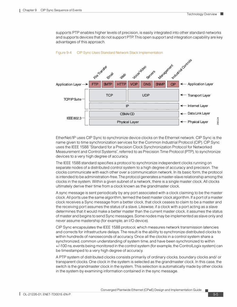
Chapter 9 CIP Sync Sequence of Events Technology Overview
supports PTP enables higher levels of precision, is easily integrated into other standard networks and supports devices that do not support PTP. This open support and integration capability are key advantages of this approach.
Figure 9-4 CIP Sync Uses Standard Network Stack Implementation
EtherNet/IP uses CIP Sync to synchronize device clocks on the Ethernet network. CIP Sync is the name given to time synchronization services for the Common Industrial Protocol (CIP). CIP Sync uses the IEEE 1588 “Standard for a Precision Clock Synchronization Protocol for Networked Measurement and Control Systems”, referred to as Precision Time Protocol (PTP), to synchronize devices to a very high degree of accuracy.
The IEEE 1588 standard specifies a protocol to synchronize independent clocks running on separate nodes of a distributed control system to a high degree of accuracy and precision. The clocks communicate with each other over a communication network. In its basic form, the protocol is intended to be administration-free. The protocol generates a master-slave relationship among the clocks in the system. Within a given subnet of a network, there is a single master clock. All clocks ultimately derive their time from a clock known as the grandmaster clock.
A sync message is sent periodically by any port associated with a clock claiming to be the master clock. All ports use the same algorithm, termed the best master clock algorithm. If a port of a master clock receives a Sync message from a better clock, that clock ceases to claim to be a master and the receiving port assumes the status of a slave. Likewise, if a clock with a port acting as a slave determines that it would make a better master than the current master clock, it assumes the status of master and begins to send Sync messages. Some nodes may be implemented as slave only and never assume mastership (for example, an I/O device).
CIP Sync encapsulates the IEEE 1588 protocol, which measures network transmission latencies and corrects for infrastructure delays. The result is the ability to synchronize distributed clocks to within hundreds of nanoseconds of accuracy. Once all the clocks in a control system share a synchronized, common understanding of system time, and have been synchronized to within +/-100 ns, events being monitored in the control system (for example, the ControlLogix system) can be timestamped to a very high degree of accuracy.
A PTP system of distributed clocks consists primarily of ordinary clocks, boundary clocks and/ or transparent clocks. One clock in the system is selected as the grandmaster clock. In this case, the switch is the grandmaster clock in the system. This selection is automatically made by other clocks in the system by examining information contained in the sync message.
2901
24
Application Layer
File T
ransfe
r
Web
Voice
/Vide
o
Serve
rs
Manag
emen
t
Transport Layer
Internet Layer
Data Link Layer
Physical LayerIEEE 802.3
TCP/IP Suite
Application Layer FTP SMTP HTTP
IP
CSMA/CD
Physical Layer
VOIP DNS SNMP
TCP UDP
CIP
Indus
trial
Cont
rols
9-5Converged Plantwide Ethernet (CPwE) Design and Implementation Guide
OL-21226-01, ENET-TD001E-EN-P

Chapter 9 CIP Sync Sequence of Events Technology Overview
Figure 9-5 shows a typical configuration.
Figure 9-5 Sample System with Grandmaster, Boundary, Transparent, and Slave Clocks
To read more about 1588 PTP (Precision Time Protocol and Synchronizing Mechanism), see the Rockwell Automation publication A-AT003A-EN-P, Integrated Architecture and CIP Sync Application Technique.
This and other reference documents can be found on the Rockwell Automation Literature Library at the following URL: http://www.rockwellautomation.com/literature.
2916
17
GPSGrand Master
TimeSlave
Switch withBoundary Clock
functions
Switch
TimeSlave
TimeSlave
Switch withBoundary Clock
functions
TimeSlave
TimeSlave
TimeSlave
TimeSlave
M
S
M M
GM
S
S
S
MMM
SS S
SS
M
TimeSlave
TimeSlave
TC TC TC
TC
9-6Converged Plantwide Ethernet (CPwE) Design and Implementation Guide
OL-21226-01, ENET-TD001E-EN-P

Chapter 9 CIP Sync Sequence of Events Technology Overview
Real-Time Synchronization in Logix ArchitectureThis section describes Rockwell Automation products that support real-time synchronization, and explains the differences between PTP and ControlLogix clock synchronization mechanisms.
Rockwell Automation Devices That Support CIP Sync
These Rockwell Automation Logix devices support CIP Sync and are discussed in this document:
• 1756-L6x and 1756-L7x controllers, version 18 and later
These modules are the Programmable Automation Controllers (PAC) of the ControlLogix family. These controllers support the CIP Sync Object, firmware revision v18 and above, and can be configured as a time source and/ or a 1588 PTP (v2) grandmaster (GM) of time on the Ethernet network.
• 1756-EN2T and 1756 1756-EN2TR modules
These are Ethernet bridge modules for the Control Logix family and support the 1588PTP (v2) CIP Sync Object firmware revision V3.0 and above. These Ethernet modules are configured as boundary clocks by default and propagate UTC time to and from the PAC controller, digital I/O that reside in the same chassis, and the Ethernet network.
• 1756-IB16ISOE and 1732E-IB16M12SOEDR modules
These are digital input modules that support the 1588PTP(v2) CIP Sync Object and are specifically designed for sequence of events (SOE) applications, firmware revision V2.7 and above. They are capable of returning timestamps with worst-case accuracy for all 16 points of 50 microseconds. The modules also have the ability to buffer up to 160 I/O point transitions locally to alleviate burst conditions that might otherwise cause data loss at the controller when multiple transitions occur in a short time frame. The SOE module returns timestamps for each I/O point transition as a 64-bit number (two 32-bit words).
• 1756HP-Time module
This is a GPS module that acquires GMT time from a group of satellites and can be used as the Real Time Source. With the addition of an embedded two port Ethernet switch that supports a Device Level Ring (DLR) topology and the 1588 PTP (v2) CIP Sync Object, the module can be configured as the grandmaster of time on the Ethernet network.
The module can be configured as a PTP (GM) and/or an NTP Server. The module is manufactured by HiProm Inc. (http://www.hiprom.com/).
• Stratix 8000 and Stratix 8300 Switch—The Stratix 8000 is a Layer 2 Ethernet managed switch. The Stratix 8300 is a Layer 2 and Layer 3 Ethernet managed switch with traffic routing capabilities. Both switches are based on Cisco technology.
These modular, managed switches use the current Cisco Catalyst switch architecture and feature set, along with powerful configuration tools. These features provide secure integration with the enterprise network, using tools familiar to IT professionals.
The 1783-MS10T Stratix 8000 Ethernet managed switch base unit supports the 1588PTP(V2) protocol and can be configured in Transparent Clock mode, Boundary Clock mode, or Forward mode per port for the propagation of PTP packets from one port to another.
Note The 1783-MX08T copper and 1783- MX08F fiber expansion modules do not support and cannot be configured for Transparent Clock or Boundary Clock modes, but will forward PTP traffic in v6 of Cisco IOS Software.
9-7Converged Plantwide Ethernet (CPwE) Design and Implementation Guide
OL-21226-01, ENET-TD001E-EN-P

Chapter 9 CIP Sync Sequence of Events Technology Overview
Now apply CIP Sync to a real time ControlLogix system. As shown in Figure 9-6, system time is passed at a 1-second interval from the grandmaster (GM) controller (L6x), through the 1756-EN2TR module configured as a boundary clock, to all slave (S) devices on the Ethernet network. The slave device clocks are now synchronized to within +/- 100 nanoseconds. This level of synch resolution enables the system to timestamp events to the 1 -microsecond resolution. Because the clocks are all synchronized, this allows precise correlation of those events that occur within the PTP network. Once the events have been timestamped (TS) by the SOE input modules, the timestamped events are sent to a database running on a PC higher in the architecture via the controller. If multiple L6x controllers are installed in the system, the controllers Wall Clock Times (WCT) are synchronized as well.
Figure 9-6 Rockwell Automation Real-Time SOE Control System on the EtherNet/IP Network
Difference between the 1588 PTP and ControlLogix Clock Synchronization Resolution
Historically, the ControlLogix backplane has used a mechanism called Coordinated System Time (CST) to synchronize modules across the backplane. This clock has a resolution of 1 microsecond of accuracy, and was used to synchronize motion, and also to synchronize the 1756-IB16SOE sequence of events modules with the ControlLogix controller.
As the IEEE 1588 PTP protocol has been layered into this architecture, the translation of time from the ControlLogix backplane to a PTP implementation is managed via the EtherNet/IP modules. (These include the 1756-EN2T, 1756-EN2TR, 1756-EN3T and 1756-EN3TR modules.) Although strictly speaking, a boundary clock is defined as one module with two PTP ports, the meaning of that definition is extended to include the ControlLogix EtherNet/IP modules, which translate time from
2902
61
E
N
2
T
R
L
6
X
GM
S
O
E
D
O
U
T
E
N
2
T
R
S
O
EL
6
X
M S
S S
Event TS done here.
Event TS done here.
Controller Clocks Synched
CLX
Chassis
#1
CLX
Chassis
#2
1732E-
IB16M12SOEDR
Armor Block I/O #1
1732E-
IB16M12SOEDR
Armor Block I/O #2
Stratix 8000
Stratix 8000
S M SSSM
E
N
2
T
R
L
6
X
GMGM
S
O
E
D
O
U
T
E
N
2
T
R
S
O
EL
6
X
MM SS
SS SS
Event TS done here.Event TS
done here.Event TS
done here.Event TS
done here.
Controller Clocks Synched
CLX
Chassis
#1
CLX
Chassis
#2
1732E-
IB16M12SOEDR
Armor Block I/O #1
1732E-
IB16M12SOEDR
Armor Block I/O #2
Stratix 8000
Stratix 8000
SS MM SSSSSSMM
Controller Clocks Synched
Controller Clocks Synched
9-8Converged Plantwide Ethernet (CPwE) Design and Implementation Guide
OL-21226-01, ENET-TD001E-EN-P

Chapter 9 CIP Sync Sequence of Events Technology Overview
CST to PTP and back again. For any time system that uses a path through the ControlLogix backplane, time accuracy and resolution is only as accurate as the clock that has the least accuracy or resolution—which, in this case, is 1 μs. (See Figure 9-7.)
Figure 9-7 The Control Logix Backplane Has a Synchronization Resolution of +/- 1μs.
Another implementation for setting up time in the system is to use the 1756HP-Time module. The 1756HP-Time module is a GPS module capable of acting as the real-time source and grandmaster of the Ethernet network. In this situation, system time is sent across the network first via the Ethernet port on the front of the GPS module. The 1756-EN2TR modules, which act as boundary clocks, receive time from the GPS module via the Ethernet infrastructure, and then pass system time into the ControlLogix backplane. System time is distributed to all SOE modules, 1756-L6x and 1756-L7x controllers, and other 1756-EN2TR modules across the backplane. (See Figure 9-8).
2902
63
EN2TR
L6X
SOE
DOUT
EN2TR
SOE L
6X
CLXChassis
#1
Clocks on the Networkare synchronized to+/- 100 Nanosecond
Resolution
CST Clocks on the ControlLogixbackplane are synchronized to a
1-microsecond Resolution
CLXChassis
#2
CLXChassi
#3
1732E-IB16M12SOEDR
Armor Block I/O #3
1732E-IB16M12SOEDR
Armor Block I/O #1
Stratix 8000
S
1732E-IB16M12SOEDR
Armor Block I/O #2
SS
S
S
GM
EN2TR
SOE L
6X
SM
S SMS S SM
System TimeSource
BoundaryClock
BoundaryClock
BoundaryClock
9-9Converged Plantwide Ethernet (CPwE) Design and Implementation Guide
OL-21226-01, ENET-TD001E-EN-P
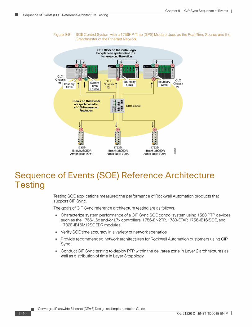
Chapter 9 CIP Sync Sequence of Events Sequence of Events (SOE) Reference Architecture Testing
Figure 9-8 SOE Control System with a 1756HP-Time (GPS) Module Used as the Real-Time Source and the Grandmaster of the Ethernet Network
Sequence of Events (SOE) Reference Architecture Testing
Testing SOE applications measured the performance of Rockwell Automation products that support CIP Sync.
The goals of CIP Sync reference architecture testing are as follows:
• Characterize system performance of a CIP Sync SOE control system using 1588 PTP devices such as the 1756-L6x and/or L7x controllers, 1756-EN2TR, 1783-ETAP, 1756-IB16ISOE, and 1732E-IB16M12SOEDR modules
• Verify SOE time accuracy in a variety of network scenarios
• Provide recommended network architectures for Rockwell Automation customers using CIP Sync
• Conduct CIP Sync testing to deploy PTP within the cell/area zone in Layer 2 architectures as well as distribution of time in Layer 3 topology.
2902
64
EN2TR
L6X
SOE
GPS
EN2TR
SOE L
6XCLX
Chassis#1
Clocks on the Networkare synchronized to+/- 100 Nanosecond
Resolution
CST Clocks on the ControlLogixbackplane are synchronized to a
1-microsecond Resolution
CLXChassis
#2
CLXChassis
#3
1732E-IB16M12SOEDR
Armor Block I/O #3
1732E-IB16M12SOEDR
Armor Block I/O #1
Stratix 8000
S
1732E-IB16M12SOEDR
Armor Block I/O #2
SS
S
SGM
EN2TR
SOE L
6X
SS
M S SMS S SM
SystemTime
Source
BoundryClock
BoundaryClock
BoundaryClock
9-10Converged Plantwide Ethernet (CPwE) Design and Implementation Guide
OL-21226-01, ENET-TD001E-EN-P
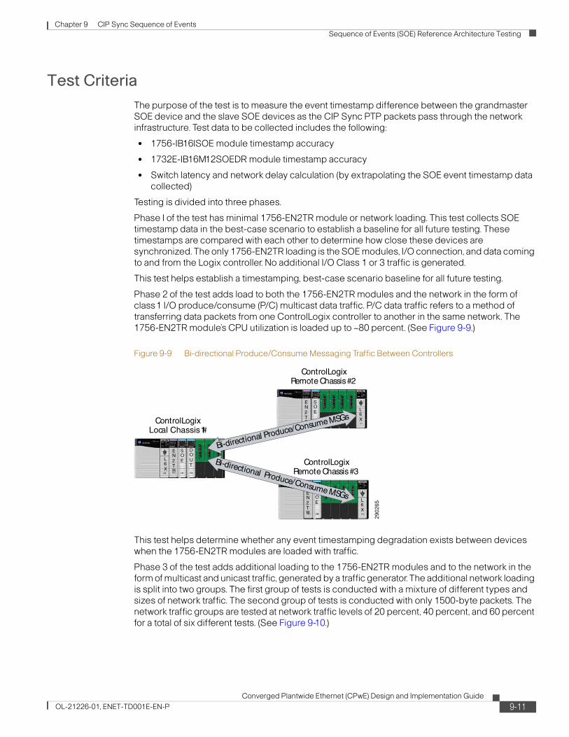
Chapter 9 CIP Sync Sequence of Events Sequence of Events (SOE) Reference Architecture Testing
Test CriteriaThe purpose of the test is to measure the event timestamp difference between the grandmaster SOE device and the slave SOE devices as the CIP Sync PTP packets pass through the network infrastructure. Test data to be collected includes the following:
• 1756-IB16ISOE module timestamp accuracy
• 1732E-IB16M12SOEDR module timestamp accuracy
• Switch latency and network delay calculation (by extrapolating the SOE event timestamp data collected)
Testing is divided into three phases.
Phase I of the test has minimal 1756-EN2TR module or network loading. This test collects SOE timestamp data in the best-case scenario to establish a baseline for all future testing. These timestamps are compared with each other to determine how close these devices are synchronized. The only 1756-EN2TR loading is the SOE modules, I/O connection, and data coming to and from the Logix controller. No additional I/O Class 1 or 3 traffic is generated.
This test helps establish a timestamping, best-case scenario baseline for all future testing.
Phase 2 of the test adds load to both the 1756-EN2TR modules and the network in the form of class1 I/O produce/consume (P/C) multicast data traffic. P/C data traffic refers to a method of transferring data packets from one ControlLogix controller to another in the same network. The 1756-EN2TR module’s CPU utilization is loaded up to ~80 percent. (See Figure 9-9.)
Figure 9-9 Bi-directional Produce/Consume Messaging Traffic Between Controllers
This test helps determine whether any event timestamping degradation exists between devices when the 1756-EN2TR modules are loaded with traffic.
Phase 3 of the test adds additional loading to the 1756-EN2TR modules and to the network in the form of multicast and unicast traffic, generated by a traffic generator. The additional network loading is split into two groups. The first group of tests is conducted with a mixture of different types and sizes of network traffic. The second group of tests is conducted with only 1500-byte packets. The network traffic groups are tested at network traffic levels of 20 percent, 40 percent, and 60 percent for a total of six different tests. (See Figure 9-10.)
2902
65
EN2TR
L6X
SOE
DOUT
ControlLogixLocal Chassis #1
EN2TR
SOE L
6X
ControlLogixRemote Chassis #2
EN2TR
SOE L
6X
ControlLogixRemote Chassis #3
Bi-directional Produce/Consume MSGs
Bi-directional Produce/Consume MSGs
9-11Converged Plantwide Ethernet (CPwE) Design and Implementation Guide
OL-21226-01, ENET-TD001E-EN-P

Chapter 9 CIP Sync Sequence of Events Sequence of Events (SOE) Reference Architecture Testing
Figure 9-10 Additional Network Loading Added by the Ixia Traffic Generator
This test helps determine whether there is any additional SOE event timestamping degradation between devices when the network is loaded down with different forms of traffic.
Calculating Chassis-based vs. Remote Modules Timestamping Accuracy
Timestamp (TS) data is collected from three 1756-IB16ISOE modules in the system. One 1756-IB16ISOE module resides in the local (GM) chassis and two additional 1756-IB16ISOE modules reside in their own remote chassis. The remote 1756-IB16ISOE module TS data is compared with the local (GM) 1756-IB16ISOE module TS data, and the time difference is calculated within the ControlLogix controller and logged into μs data groupings. These timestamp results are exported to an Excel spreadsheet for display. Figure 9-11 shows an example of how the timestamp data appears, along with the minimum, maximum, and average results.
The majority of the timestamp data captured ranges between no timestamp difference indicated by a value of zero to about 26 μs. A difference of zero means the device clock times were identical at the time of the event. A maximum timestamp difference of 64 μs was recorded, but the number of times it fell within this range was small enough (1–2 samples), that it did not register on the graph in Figure 9-11.
• Local56SOE(TS)—Rem56SOE1(TS) = 56SOE(TS) Diff_11
• Local56SOE(TS)—Rem56SOE2(TS) = 56SOE(TS) Diff_12
2916
18
EN2TR
L6X
SOE
DOUT
Control LogixLocal Chassis
#1
1732E-IB16M12SOEDRArmor Block I/O
Stratix 8000
S
SGM
M
S
IXIA BoxTraffic
Generator
IXIA OUTIXIA IN
9-12Converged Plantwide Ethernet (CPwE) Design and Implementation Guide
OL-21226-01, ENET-TD001E-EN-P
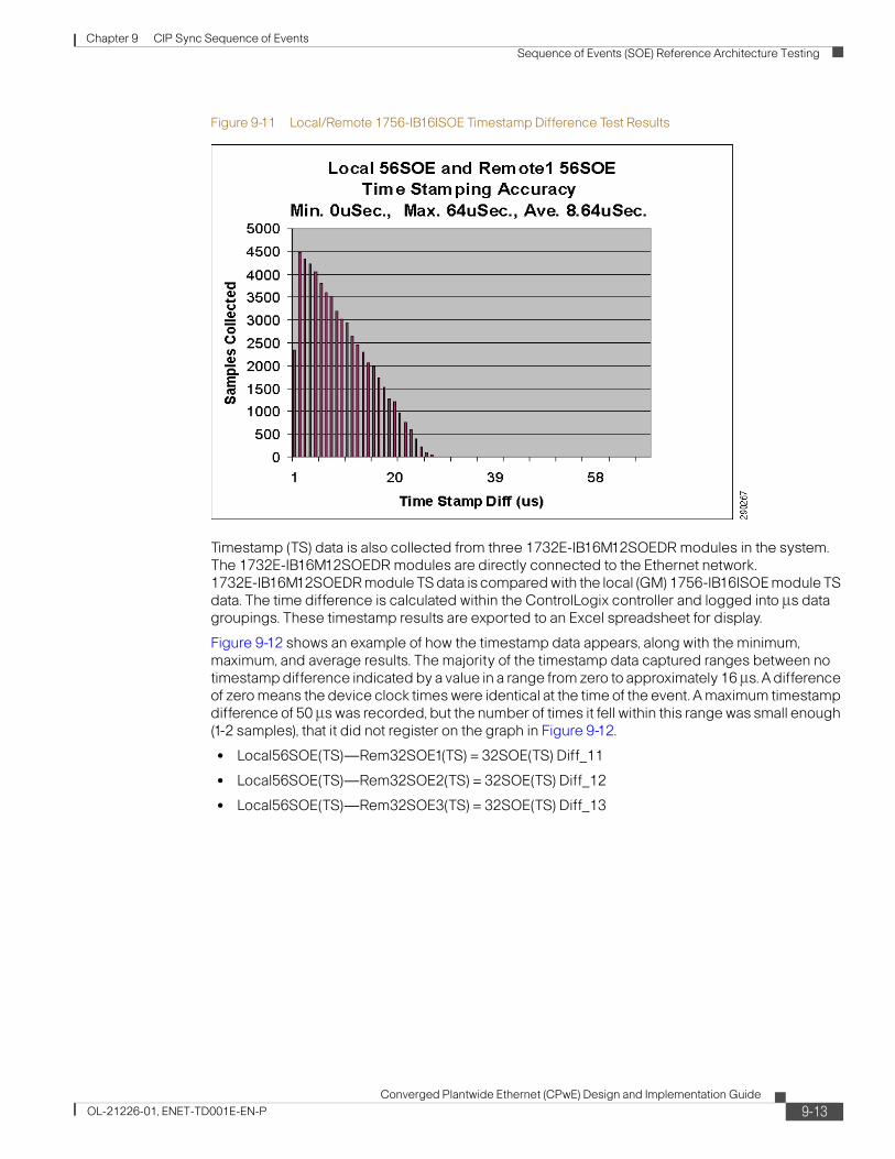
Chapter 9 CIP Sync Sequence of Events Sequence of Events (SOE) Reference Architecture Testing
Figure 9-11 Local/Remote 1756-IB16ISOE Timestamp Difference Test Results
Timestamp (TS) data is also collected from three 1732E-IB16M12SOEDR modules in the system. The 1732E-IB16M12SOEDR modules are directly connected to the Ethernet network. 1732E-IB16M12SOEDR module TS data is compared with the local (GM) 1756-IB16ISOE module TS data. The time difference is calculated within the ControlLogix controller and logged into μs data groupings. These timestamp results are exported to an Excel spreadsheet for display.
Figure 9-12 shows an example of how the timestamp data appears, along with the minimum, maximum, and average results. The majority of the timestamp data captured ranges between no timestamp difference indicated by a value in a range from zero to approximately 16 μs. A difference of zero means the device clock times were identical at the time of the event. A maximum timestamp difference of 50 μs was recorded, but the number of times it fell within this range was small enough (1-2 samples), that it did not register on the graph in Figure 9-12.
• Local56SOE(TS)—Rem32SOE1(TS) = 32SOE(TS) Diff_11
• Local56SOE(TS)—Rem32SOE2(TS) = 32SOE(TS) Diff_12
• Local56SOE(TS)—Rem32SOE3(TS) = 32SOE(TS) Diff_13
9-13Converged Plantwide Ethernet (CPwE) Design and Implementation Guide
OL-21226-01, ENET-TD001E-EN-P
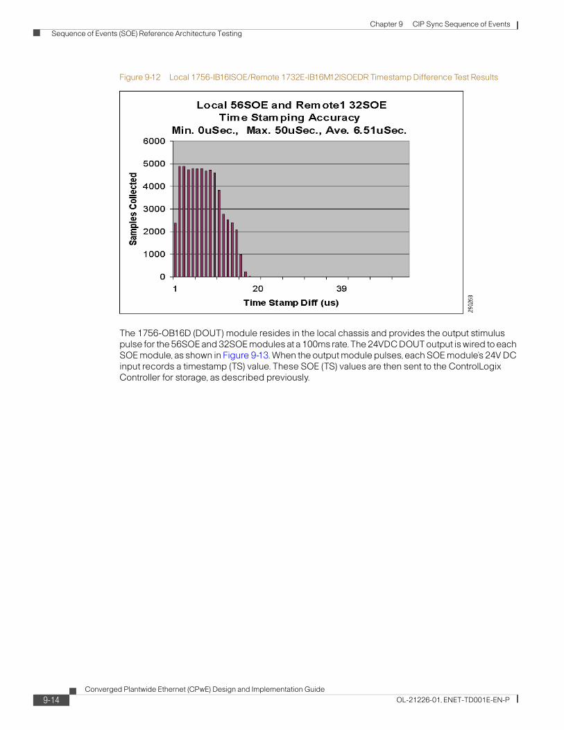
Chapter 9 CIP Sync Sequence of Events Sequence of Events (SOE) Reference Architecture Testing
Figure 9-12 Local 1756-IB16ISOE/Remote 1732E-IB16M12ISOEDR Timestamp Difference Test Results
The 1756-OB16D (DOUT) module resides in the local chassis and provides the output stimulus pulse for the 56SOE and 32SOE modules at a 100ms rate. The 24VDC DOUT output is wired to each SOE module, as shown in Figure 9-13. When the output module pulses, each SOE module’s 24V DC input records a timestamp (TS) value. These SOE (TS) values are then sent to the ControlLogix Controller for storage, as described previously.
9-14Converged Plantwide Ethernet (CPwE) Design and Implementation Guide
OL-21226-01, ENET-TD001E-EN-P

Chapter 9 CIP Sync Sequence of Events Sequence of Events (SOE) Reference Architecture Testing
Figure 9-13 Diagram of the Output Stimulus and SOE Module Wiring
2902
69
ControlLogixLocal Chassis #1 ControlLogix
Remote Chassis #2
ControlLogixRemote Chassis #3
EN2TR
L6X
SOE
DOUT E
N2TR
SOE L
6X
EN2TR
SOE L
6X
Local56SOE-Rem56SOE1=56TSDiff_11
Local56SOE-Rem56SOE2=56TSDiff_12
Local56SOE-Rem32SOE1=32TSDiff_11
Local56SOE-Rem32SOE2=32TSDiff_12
Local56SOE-Rem32SOE3=32TSDiff_13
24VDC Output Pulse @100ms
Local 56SOE and Remote1 56SOE
Time Stamping Accuracy (A to B)
Min. 0uSec., Max. 64uSec., Ave. 8.64uSec.
0
1000
2000
3000
4000
5000
1 20 39 58
Time Stamp Diff (us)
Sa
mp
les
Co
lle
cte
d
Local 56SOE and Remote2 56SOE
Time Stamping Accuracy (A to C)
Min. 0uSec., Max. 53uSec., Ave. 8.43uSec.
0
1000
2000
3000
4000
5000
1 20 39 58
Time Stamp Diff (us)
Sa
mp
les
Co
lle
cte
d
Local 56SOE and Remote1 32SOE
Time Stamping Accuracy (A to D)
Min. 0uSec., Max. 50uSec., Ave. 6.51uSec.
0
1000
2000
3000
4000
5000
6000
1 20 39
Time Stamp Diff (us)
Sa
mp
les
Co
lle
cte
d
Local 56SOE and Remote2 32SOE
Time Stamping Accuracy (A to E)
Min. 0uSec., Max. 50uSec., Ave. 6.42uSec.
0
1000
2000
3000
4000
5000
6000
1 20 39
Time Stamp Diff (us)
Sa
mp
les
Co
lle
cte
d
Local 56SOE and Remote3 32SOE
Time Stamping Accuracy (A to F)
Min. 0uSec., Max. 49uSec., Ave. 6.67uSec.
0
1000
2000
3000
4000
5000
6000
1 20 39
Time Stamp Diff (us)
Sa
mp
les
Co
lle
cte
d
1732E-IB16M12SOEDR
Armor Block I/O #1
1732E-IB16M12SOEDR
Armor Block I/O #2
1732E-IB16M12SOEDR
Armor Block I/O #3
9-15Converged Plantwide Ethernet (CPwE) Design and Implementation Guide
OL-21226-01, ENET-TD001E-EN-P
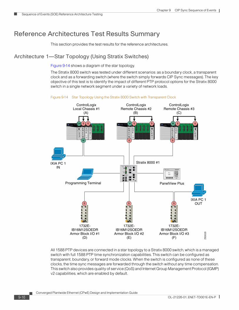
Chapter 9 CIP Sync Sequence of Events Sequence of Events (SOE) Reference Architecture Testing
Reference Architectures Test Results SummaryThis section provides the test results for the reference architectures.
Architecture 1—Star Topology (Using Stratix Switches)
Figure 9-14 shows a diagram of the star topology.
The Stratix 8000 switch was tested under different scenarios: as a boundary clock, a transparent clock and as a forwarding switch (where the switch simply forwards CIP Sync messages). The key objective of this test is to identify the impact of different PTP protocol options for the Stratix 8000 switch in a single network segment under a variety of network loads.
Figure 9-14 Star Topology Using the Stratix 8000 Switch with Transparent Clock
All 1588 PTP devices are connected in a star topology to a Stratix 8000 switch, which is a managed switch with full 1588 PTP time synchronization capabilities. This switch can be configured as transparent, boundary, or forward mode clocks. When the switch is configured as none of these clocks, the time sync messages are forwarded through the switch without any time compensation. This switch also provides quality of service (QoS) and Internet Group Management Protocol (IGMP) v2 capabilities, which are enabled by default.
2916
19
EN2TR
L6X
SOE
DOUT
EN2TR
SOE L
6X
1732E-IB16M12SOEDR
Armor Block I/O #3(F)
1732E-IB16M12SOEDR
Armor Block I/O #1(D)
Stratix 8000 #1
S
1732E-IB16M12SOEDR
Armor Block I/O #2(E)
SS
S
EN2TR
SOE L
6X
S
IXIA PC 1OUT
IXIA PC 1IN
Programming Terminal PanelView Plus
ControlLogixLocal Chassis #1
(A)
ControlLogixRemote Chassis #2
(B)
ControlLogixRemote Chassis #3
(C)
SGM
M
M MS S S S S
9-16Converged Plantwide Ethernet (CPwE) Design and Implementation Guide
OL-21226-01, ENET-TD001E-EN-P

Chapter 9 CIP Sync Sequence of Events Sequence of Events (SOE) Reference Architecture Testing
The ControlLogix controller is the grandmaster (GM) of time and passes PTP packets to all CIP Sync slave (S; red dot) devices on the network.
The Ixia traffic generator is connected to the 1756-EN2TR Ethernet module port located in the Local ControlLogix chassis and introduces various types and sizes of Ethernet traffic to stress the network. The Ixia PC Ethernet traffic exits the Armor Block Ethernet port of 1732E-IB16M12SOEDR module number 3.
A three-phase test determines the SOE event timestamping accuracy between the GM device transmitting the time data and the slave devices receiving this time data.
A second series of tests is conducted using a Stratix 6000 switch, which is a managed switch with IGMP v2 capabilities, but with no 1588 PTP capabilities. A third series of tests is conducted using a Stratix 2000 switch, which is an unmanaged switch and has no 1588 PTP, QoS, or IGMP capabilities.
The fluctuation in SOE timestamp accuracy with different types of network traffic loading can be seen in Table 9-1and Figure 9-15.
Table 9-1 Star Topology SOE Timestamp Test Results
Test Revisions (μs)Stratix 8000 (Transparent)
Stratix 8000 (Boundary
Stratix 8000 (Forward) Stratix 6000 Stratix 2000
No Load Min
Max
Avg,
0
648.64
0
61
8.47
0
62
8.48
0
61
8.47
0
63
8.49
1756-EN2TR ~80% Loading
Min
Max
Avg,
0
64
8.44
0
67
8.48
0
59
8.49
0
64
8.53
0
65
8.51
Ixia traffic 20% Mixed Loading And 1756-EN2TR ~80% Loading
Min
Max
Avg,
0
63
8.45
0
62
8.83
0
64
8.47
0
69
8.53
0
63
8.55
Ixia traffic 40% Mixed Loading and 1756-EN2TR ~80% Loading
Min
Max
Avg,
0
68
8.48
0
63
8.46
0
68
8.53
0
63
8.52
0
69
8.62
Ixia traffic 60% Mixed Loading and 1756-EN2TR ~80% Loading
Min
Max
Avg,
0
60
8.45
0
60
8.50
0
68
8.78
0
66
8.71
0
70
8.81
Ixia traffic 20% 1500 Loading and 1756-EN2TR ~80% Loading
Min
Max
Avg,
0
65
8.43
0
62
8.48
0
143
36.96
0
149
39.06
0
145
40.14
Ixia traffic 40% 1500 Loading and 1756-EN2TR ~80% Loading
Min
Max
Avg,
0
65
8.45
0
60
8.48
0
124
49.47
0
128
51.57
0
137
51.41
Ixia traffic 60% 1500 Loading and 1756-EN2TR ~80% Loading
Min
Max
Avg,
0
63
8.46
0
65
8.47
0
117
46.23
0
116
48.10
0
137
49.37
9-17Converged Plantwide Ethernet (CPwE) Design and Implementation Guide
OL-21226-01, ENET-TD001E-EN-P

Chapter 9 CIP Sync Sequence of Events Sequence of Events (SOE) Reference Architecture Testing
Figure 9-15 Star Topology SOE Timestamp Test Results
Test Observations
There is a minimal change in event timestamp accuracy (average ~2 μs difference) between the No Load, 1756-EN2TR ~80 percent loading, and the Ixia mixed traffic loading; with the maximum timestamp being (MAX = 70 μs) using the Stratix 2000 switch.
When the Ixia 1500-byte traffic was injected, there is a significant difference in event timestamp accuracy (average ~45 μs difference), with the maximum timestamp being (MAX = 137 μs) using the Stratix 2000 switch.
The 1500-byte packet traffic affected only the SOE modules that were in the direct path of the Ixia traffic stream (for example, the 1732E-IB16M12SOEDR module 3). The modules were affected only if the switch between the grandmaster and slave device was a managed switch configured for forward clock (for example, the Stratix 8000 switch); a managed switch with no PTP capability (for example, the Stratix 6000 switch); or an unmanaged switch that forwards all traffic (for example, the Stratix 2000 switch).
Conclusion
There was minimal timestamp degradation between the PTP devices until 1500-byte packets of data were introduced and the Stratix 8000 switch was configured for forward clock or used a switch with no PTP capabilities. For applications that require the highest degree of synchronization, it is recommended to use a managed switch with PTP capabilities, such as transparent or boundary clock modes.
9-18Converged Plantwide Ethernet (CPwE) Design and Implementation Guide
OL-21226-01, ENET-TD001E-EN-P

Chapter 9 CIP Sync Sequence of Events Sequence of Events (SOE) Reference Architecture Testing
Architecture 2—Linear Topology (Using Embedded Dual-Port Ethernet Technology)
Figure 9-16 shows a diagram of the linear topology.
Figure 9-16 Linear Topology Using Embedded Dual-Port Ethernet Switch Devices with Transparent Clock
In this architecture, all 1588 PTP devices are connected in a linear topology. Each device is equipped with a dual-port Ethernet managed switch with 1588 PTP time synchronization capabilities. These capabilities include transparent clock mode. These switches also have QoS and IGMP v2 capabilities, which are enabled by default. Devices that do not support dual-port Ethernet switch technology are connected to the linear topology via the 1783-ETAP modules.
The ControlLogix controller is the grandmaster (GM) of time and passes PTP packets to all CIP Sync slave (S; red dot) devices on the network.
The Ixia computer is connected to the 1756-EN2TR module’s Ethernet port located in the local ControlLogix chassis and introduces various types and sizes of additional Ethernet traffic to stress the network. The Ixia computer Ethernet traffic exits the 1783-ETAP module 1 Ethernet port at the end of the physical network.
A three-phase test is conducted to determine the SOE Event timestamping accuracy between the GM device transmitting the time data and the slave devices receiving this time data.
2916
20
EN2TR
L6X
SOE
DOUT
EN2TR
SOE L
6X
1732E-IB16M12SOEDR
Armor Block I/O #3(F)
1732E-IB16M12SOEDR
Armor Block I/O #1(D)
1783-ETAP #21783-ETAP #1
S
1732E-IB16M12SOEDR
Armor Block I/O #2(E)
SS
EN2TR
SOE L
6X
IXIA PC 1OUT
IXIA PC 1IN
PanelViewPlus
ProgrammingTerminal
SS
ControlLogixLocal Chassis #1
(A)
ControlLogixRemote Chassis #2
(B)
ControlLogixRemote Chassis #3
(C)
SGM
M
M MS S S S S
9-19Converged Plantwide Ethernet (CPwE) Design and Implementation Guide
OL-21226-01, ENET-TD001E-EN-P

Chapter 9 CIP Sync Sequence of Events Sequence of Events (SOE) Reference Architecture Testing
Architecture 3—Ring Topology (Device Level Ring Technology)
Figure 9-17 shows a diagram of the ring topology.
Figure 9-17 Ring Topology Using Embedded Dual-Port Ethernet Switch Devices with Transparent Clock
All 1588 PTP devices are connected to each other in a ring topology. The linear topology described previously has now been physically closed to form a ring topology by using Device Level Ring (DLR) technology. Each device is equipped with a dual-port Ethernet managed switch 1588 PTP time synchronization capabilities. These capabilities include transparent clock mode. These switches also have QoS and IGMP v2 capabilities, which are enabled by default. Devices that do not support the dual-port Ethernet switch technology are connected to the linear topology via the 1783-ETAP modules.
The Logix controller is the grandmaster (GM) of time and passes PTP packets to all CIP Sync slave (S; red dot) devices on the network.
The Ixia PC is connected to the 1783-ETAP module 1 Ethernet port and injects various types and sizes of additional Ethernet traffic to stress the network. The Ixia computer Ethernet traffic exits the 1783-ETAP module 4 Ethernet port in the middle of the physical network.
A three-phase test determines the SOE Event timestamping accuracy between the GM device transmitting the time data and the slave devices receiving this time data.
The fluctuation in SOE timestamp accuracy with various types of network traffic loading can be seen in Table 9-2 and Figure 9-18.
2916
21
EN2TR
L6X
SOE
DOUT
EN2TR
SOE L
6X
1732E-IB16M12SOEDR
Armor Block I/O #3(F)
1732E-IB16M12SOEDR
Armor Block I/O #1(D)
1783ETAP #2
1783ETAP #1
1783ETAP #3
1783ETAP #4
S
1732E-IB16M12SOEDR
Armor Block I/O #2(E)
SS
EN2TR
SOE L
6X
IXIA PC 1IN
PanelViewPlus
ProgrammingTerminal
IXIA PC 1OUT
T
SS
ControlLogixLocal Chassis #1
(A)
ControlLogixRemote Chassis #2
(B)
ControlLogixRemote Chassis #3
(C)
SGM
M
M MS S S S S
9-20Converged Plantwide Ethernet (CPwE) Design and Implementation Guide
OL-21226-01, ENET-TD001E-EN-P

Chapter 9 CIP Sync Sequence of Events Sequence of Events (SOE) Reference Architecture Testing
Figure 9-18 Linear and Ring Topology SOE Timestamp Test Results
Table 9-2 Linear and Ring Topology SOE Timestamp Test Results
Test Revisions (μs) Linear Topology Device Level Ring
No Load Min
Max
Avg.
0
65
8.64
0
67
8.52
1756-EN2TR ~80% Loading Min
Max
Avg.
0
60
8.45
0
60
8.47
Ixia traffic 20% Mixed Loading and 1756-EN2TR ~80% Loading
Min
Max
Avg.
0
65
8.46
0
66
8.47
Ixia traffic 40% Mixed Loading and 1756-EN2TR ~80% Loading
Min
Max
Avg.
0
63
8.47
0
65
8.48
Ixia traffic 60% Mixed Loading and 1756-EN2TR ~80% Loading
Min
Max
Avg.
0
63
8.45
0
63
8.49
Ixia traffic 20% 1500 Loading and 1756-EN2TR ~80% Loading
Min
Max
Avg.
0
62
8.48
0
8.46
Ixia traffic 40% 1500 Loading and 1756-EN2TR ~80% Loading
Min
Max
Avg
0.
65
8.50
0
63
8.48
Ixia traffic 60% 1500 Loading and 1756-EN2TR ~80% Loading
Min
Max
Avg.
0
62
8.46
0
63
8.48
9-21Converged Plantwide Ethernet (CPwE) Design and Implementation Guide
OL-21226-01, ENET-TD001E-EN-P

Chapter 9 CIP Sync Sequence of Events Sequence of Events (SOE) Reference Architecture Testing
Test Observations
There is a minimal change in timestamp accuracy (average ~.17 μs difference) between the local SOE module (GM Chassis A) and the remote SOE modules (slave Chassis B and C/Modules D, E, and F) hopping through each device’s embedded dual Ethernet switch, with the maximum being (MAX = 69 μs).
The Ixia 1500-byte packet traffic did not negatively affect the timestamping accuracy.
Conclusion
There was minimal timestamp degradation between the PTP devices. This is attributed to the embedded switch technology being set for transparent clock mode (TM) by default and performing as well as the Stratix 8000 switch configured for transparent clock mode.
Architecture 4—Multiple Star Topology
The multiple star topology consists of separated network segments using the 1756-EN2T modules in boundary clock mode. (See Figure 9-19.)
The Stratix 8000 switch was tested under different scenarios: as a boundary clock, a transparent clock and as a forwarding switch (where the switch simply forwards CIP Sync messages). The key objective of this test is to identify the impact of different PTP protocol options and performance for the Stratix 8000 switches in three network segments under a variety of network loads.
9-22Converged Plantwide Ethernet (CPwE) Design and Implementation Guide
OL-21226-01, ENET-TD001E-EN-P

Chapter 9 CIP Sync Sequence of Events Sequence of Events (SOE) Reference Architecture Testing
Figure 9-19 Multiple Star Topology Segmented by 1756-EN2T Modules with Boundary Clock and Stratix 8000 Switch with Transparent Clock.
All 1588 PTP devices are connected in a multiple star topology segmented by a 1756-EN2T module acting as a boundary clock to the next network segment.
Each star topology segment is connected to a Stratix 8000 switch. The Stratix 8000 switch is a managed switch with full 1588 PTP time synchronization capabilities. These capabilities include transparent, boundary, and forward clock modes. This switch also has QoS and IGMP v2 capabilities, which are enabled by default.
The Logix controller is the grandmaster (GM) of time and passes PTP packets to all CIP Sync slave (S; red dot) devices in the first segment. The GM time is passed to additional segments by using the 1756-EN2T module acting as a boundary clock, which in turn acts as the master (M) of time for its own network segment.
The Ixia PC is connected to the 1756-EN2TR module’s Ethernet port, located in the local ControlLogix chassis number 1; and introduces various types and sizes of additional Ethernet traffic to stress the network. The Ixia PC Ethernet traffic exits the 1732E-IB16M12SOEDR module 1 Armor Block Ethernet port.
A three-phase test is conducted to determine the SOE event timestamping accuracy between the GM device transmitting the time data and the slave devices receiving this time data.
A second series of tests is conducted using a Stratix 6000 switch, which is a managed switch with IGMP v2 capabilities. The Stratix 6000 switch has no 1588 PTP capabilities. A third series of tests is conducted using a Stratix 2000 switch, which is an unmanaged switch with no 1588 PTP or IGMP capabilities.
2916
22
Stratix8000
#1
Stratix8000
#2
Stratix8000
#3
BoundaryClock #1
1732E-IB16M12SOEDR
Armor Block I/O #1(E)
S
IXIA PC 1OUT
IXIA PC 1IN
PanelViewPlus
ControlLogixLocal Chassis #1
(A)
ControlLogixRemote Chassis #2
(B)
Segment 1
Segment 2
Segment 3ControlLogix
Remote Chassis #3(C)
ControlLogixRemote Chassis #4
(D)
ProgrammingTerminal
EN2TR
L6X
SOE
DOUT
EN2TR
SOE L
6X
EN2T
EN2TR
SOE L
6X
EN2T
EN2TR
SOE L
6X
EN2T
PanelViewPlus
S M
BoundaryClock #2
S
S
M
1732E-IB16M12SOEDR
Armor Block I/O #2(F)
S
PanelViewPlus
1732E-IB16M12SOEDR
Armor Block I/O #3(G)
S
SGM
M
S
M S S S
M S S S
M S S S
9-23Converged Plantwide Ethernet (CPwE) Design and Implementation Guide
OL-21226-01, ENET-TD001E-EN-P

Chapter 9 CIP Sync Sequence of Events Sequence of Events (SOE) Reference Architecture Testing
The Stratix 8000 boundary clock mode was not tested because the main focus was the effects of having the 1756-EN2TR modules as the boundary clocks that segmented the network.
The fluctuation in SOE timestamp accuracy with different types of network traffic loading can be seen in Table 9-3 and Figure 9-20.
Table 9-3 Multiple Star Topology SOE Timestamp Test Results
Test Revisions (μs)Stratix 8000 (Transparent)
Stratix 8000 (Forward) Stratix 6000 Stratix 2000
No Load Min
Max
Avg.
0
63
8.59
0
68
8.60
0
67
8.62
0
64
8.67
1756-EN2TR ~80%
Loading
Min
Max
Avg.
0
66
8.45
0
64
8.48
0
60
8.51
0
67
8.54
Ixia traffic 20% Mixed Loading and 1756-EN2TR ~80% Loading
Min
Max
Avg.
0
67
8.49
0
63
8.49
0
67
8.50
0
62
8.52
Ixia traffic 40% Mixed Loading and 1756-EN2TR ~80% Loading
Min
Max
Avg.
0
65
8.50
0
65
8.53
0
68
8.49
0
62
8.51
Ixia traffic 60% Mixed Loading and 1756-EN2TR ~80% Loading
Min
Max
Avg.
0
67
8.50
0
63
8.69
0
73
8.67
0
65
8.64
Ixia traffic 20% 1500 Loading and 1756-EN2TR ~80% Loading
Min
Max
Avg.
0
65
8.65
0
154
40.20
0
142
39.20
0
147
39.61
Ixia traffic 40% 1500 Loading and 1756-EN2TR ~80% Loading
Min
Max
Avg.
0
68
8.51
0
142
52.35
0
139
51.83
0
141
51.92
Ixia traffic 60% 1500 Loading and 1756-EN2TR ~80% Loading
Min
Max
Avg.
0
65
8.48
0
118
50.23
0
121
8.69
0
118
48.55
9-24Converged Plantwide Ethernet (CPwE) Design and Implementation Guide
OL-21226-01, ENET-TD001E-EN-P

Chapter 9 CIP Sync Sequence of Events Sequence of Events (SOE) Reference Architecture Testing
Figure 9-20 Multiple Star Topology SOE Timestamp Test Results
Test Observations
There was a minimal change in event timestamp accuracy (average ~2 μs difference) between the No Load, 1756-EN2TR ~80 percent loading, and the Ixia mixed traffic loading; with the maximum timestamp being (MAX = 73 μs) using the Stratix 6000 switch.
When the Ixia 1500-byte traffic was injected, there was a significant difference in event timestamp accuracy (average ~45 μs difference), with the maximum timestamp being (MAX = 147 μs) using the Stratix 2000 switch.
The 1500-byte packet traffic affected only the SOE modules that were in the direct path of the Ixia traffic stream (for example, 1732E-IB16M12SOEDR module number 1); and only if the switch between the grandmaster and slave device was a managed switch configured for forward clock (for example, a Stratix 8000 switch), a managed switch with no PTP capability (for example, Stratix 6000 switches), or an unmanaged switch that forwards all traffic (for example, Stratix 2000 switches).
Conclusion
Minimal timestamp degradation was observed between the PTP devices using the 1756-EN2TR modules as boundary clock devices to segment the architecture until the 1500-byte packets of data were injected and the Stratix 8000 switch was configured for forward clock; or a switch with no PTP capabilities was used. For applications that require a high degree of synchronization, it is recommended to use a managed switch with PTP capabilities, such as transparent or boundary clock modes.
9-25Converged Plantwide Ethernet (CPwE) Design and Implementation Guide
OL-21226-01, ENET-TD001E-EN-P

Chapter 9 CIP Sync Sequence of Events Sequence of Events (SOE) Reference Architecture Testing
Architecture 5—Star Topology
This architecture propagates PTP packets across different VLANs by using the Stratix 8300 switch in boundary clock mode. (See Figure 9-21.)
Note that the Stratix 8000 switch was tested under different scenarios: as a boundary clock, a transparent clock and as a forwarding switch (where the switch simply forwards CIP Sync messages). The key objective of this test is to identify the impact of the PTP protocol options while distributing PTP between network segments (that is, across VLANs) using both Stratix 8300 & 8000 switches under a variety of network loads.
Figure 9-21 Star Topology Segmented with VLANs Using the Stratix 8300 Switch with Boundary Clock and the Stratix 8000 Switch with Forward Clock
All 1588 PTP devices are connected in a star topology segmented by different VLANS. Each star topology segment is connected to a Stratix 8000 switch, which then connects up to a common 8300 Stratix switch. The Stratix 8000 and 8300 switches are managed switches with full 1588 PTP time synchronization capabilities. These capabilities include transparent, boundary, and forward clock modes. This switch also has QoS and IGMP v2 capabilities, which are enabled by default.
The Logix controller is the grandmaster (GM) of time and passes PTP packets to all CIP Sync slave (S; red dot) devices in VLAN10. The GM time is then passed to additional VLANs using the Stratix 8300 Layer 3 managed switch with routing capabilities that act as a boundary clock. The boundary clock in turn acts as the master (M) of time for VLAN20 and VLAN30 on the network.
2916
24
Stratix8300(BM)
Stratix8000
#2
Stratix8000
#3
VLAN 20
VLAN 30VLAN 10
PanelViewPlus
EN2TR
SOE L
6X
EN2TR
L6X
SOE
DOUT
EN2TR
SOE L
6X
Stratix8000
#1
1732E-IB16M12SOEDR
Armor Block I/O #1(D)
S
1732E-IB16M12SOEDR
Armor Block I/O #2(F)
S
S
S
IXIA PC 1OUT
IXIA PC 1IN
PanelViewPlus
ProgrammingTerminal
M
M
PanelViewPlus
1732E-IB16M12SOEDR
Armor Block I/O #3(G)
S
S
ControlLogixLocal Chassis #1
(A)
SGM
M
S
S
ControlLogixRemote Chassis #2
(B)
M S S
S
ControlLogixRemote Chassis #3
(C)
M S S
9-26Converged Plantwide Ethernet (CPwE) Design and Implementation Guide
OL-21226-01, ENET-TD001E-EN-P

Chapter 9 CIP Sync Sequence of Events Sequence of Events (SOE) Reference Architecture Testing
The Ixia PC is connected to the 1756-EN2TR Ethernet port located in the local CLX chassis and introduces various types and sizes of additional Ethernet traffic to stress the network. The Ixia PC Ethernet traffic exits the 1732E-IB16M12SOEDR module 1 Armor Block Ethernet port.
A three-phase test is conducted to determine the SOE event timestamping accuracy between the GM device transmitting the time data and the slave devices receiving this time data in the different network VLANs.
The Stratix 6000 and Stratix 2000 switches were not used in this architecture because these switches do not support VLAN trunking.
The test configuration seen in Figure 9-21 could not be conducted with the 1756-IB16ISOE module located in the remote chassis because the module does not support a unicast connection at this time. This has been shown with a red X over the Remote 56SOE modules. Instead, a simpler test was conducted with the local 56SOE and remote 32SOE modules.
The fluctuation in SOE timestamp accuracy with different types of network traffic loading can be seen in Table 9-4 and Figure 9-22.
Table 9-4 Star Topology SOE Timestamp Test Results
Test Revisions (μs)Stratix 8000 (Transparent)
Stratix 8000 (Boundary)
Stratix 8000 (Forward)
No Load Min
Max
Avg.
0
57
6.62
0
54
6.62
0
53
6.63
1756-EN2TR ~80%
Loading
Min
Max
Avg.
0
52
6.80
0
53
6.86
0
52
6.78
Ixia traffic 20% Mixed Loading and 1756-EN2TR ~80% Loading
Min
Max
Avg.
0
56
6.82
0
50
6.82
0
53
6.94
Ixia traffic 40% Mixed Loading and 1756-EN2TR ~80% Loading
Min
Max
Avg.
0
53
6.81
0
53
6.80
0
50
6.87
Ixia traffic 60% Mixed Loading and 1756-EN2TR ~80% Loading
Min
Max
Avg.
0
54
6.79
0
55
6.78
0
49
6.95
Ixia traffic 20% 1500 Loading and 1756-EN2TR ~80% Loading
Min
Max
Avg.
0
50
6.78
0
53
6.78
0
150
39.88
Ixia traffic 40% 1500 Loading and 1756-EN2TR ~80% Loading
Min
Max
Avg.
0
52
6.82
0
51
6.84
0
145
52.74
Ixia traffic 60% 1500 Loading and 1756-EN2TR ~80% Loading
Min
Max
Avg.
0
51
6.84
0
6.80
0
120
49.10
9-27Converged Plantwide Ethernet (CPwE) Design and Implementation Guide
OL-21226-01, ENET-TD001E-EN-P

Chapter 9 CIP Sync Sequence of Events Sequence of Events (SOE) Reference Architecture Testing
Figure 9-22 Star Topology SOE Timestamp Test Results
Test Observations
There was a minimal change in event timestamp accuracy (average ~.33 μs difference) between the No Load, the 1756-EN2TR ~80 percent loading, and the Ixia mixed and 1500-byte traffic loading; with the maximum timestamp being (MAX = 56us) using the Stratix 8000 switch in transparent clock (TM).
When the Ixia 1500-byte traffic was injected, there was a significant difference in event timestamp accuracy (average ~45.96 μs difference) with the maximum timestamp being (MAX = 150 μs) using the Stratix 8000 switch.
The 1500-byte packet traffic affected only SOE modules that were in the direct path of the Ixia traffic stream (for example, 1732E-IB16M12SOEDR module 1). The modules were affected only if the switch between the grandmaster and slave device was a managed switch configured for forward clock (for example, the Stratix 8000 switch).
Conclusion
Minimal timestamp degradation was observed between the PTP devices until 1500-byte packets of data were injected, and the Stratix 8000 switch was configured for forward clock. If applications require the highest degree of synchronization, it is recommended to use a managed switch with PTP capabilities, such as transparent or boundary clock modes.
9-28Converged Plantwide Ethernet (CPwE) Design and Implementation Guide
OL-21226-01, ENET-TD001E-EN-P

Chapter 9 CIP Sync Sequence of Events Design Recommendations
Design RecommendationsRockwell Automation’s design recommendations are as follows:
• Applications that require high accuracy and performance, (for example, high performance motion control) should use devices that support 1588 PTP v2 time synchronization and that implement transparent clock or boundary clock mechanisms, such as the following:
– Stratix 8000 switches (does not support the Device Level Ring Protocol)
– Kinetix 6500 drives
– ArmorBlock I/O
– 1783-ETAP module
– Point I/O
– 1756-EN2TR and 1756-EN3TR modules
– Embedded switch technology
Includes transparent clock, Device Level Ring protocol, QoS, and IGMP snooping functionality. Used in all the devices listed above.
• Applications that require less precision and accuracy (for example, general process timestamping) may not need devices such as switches or routers that support boundary or transparent clocks. However, clock synchronization is compromised and the application does not have a precise time calculation.
• These application types can be mixed on the same subnet as long as those devices that require high precision have a clear view of the system time master through the mechanisms described above. It is possible to set up the architecture to support this.
• The use of transparent or boundary clocks makes the system extremely robust for network loading variations.
• Applications that require the propagation of time from one subnet to a different subnet require end devices such as 1756-IB16ISOE and 1732E-IB16M12SOEDR modules that support PTPv2 and a unicast connection. Switches such as the Stratix 8300 switch must also support PTPv2 and transparent/boundary clock mechanisms as well.
To read more about CIP Sync device configuration and limitations, see the Rockwell Automation publication A-AT003A-EN-P, Integrated Architecture and CIP Sync Application Technique.
To read more about dual-port embedded switch device configuration and limitations, see the Rockwell Automation publication ENET-AP005C-EN-P, EtherNet/IP Embedded Switch Technology Application Guide.
These and other reference documents can be found on the Rockwell Automation Literature Library at the following URL: http://www.rockwellautomation.com/literature.
9-29Converged Plantwide Ethernet (CPwE) Design and Implementation Guide
OL-21226-01, ENET-TD001E-EN-P

Chapter 9 CIP Sync Sequence of Events Detailed Test Configuration and Results
Detailed Test Configuration and ResultsThis section explains how the tests were set up, as well as describes the test results.
Figure 9-23 shows the wiring schematic for the 1756-OB16D, 1756IB16ISOE, and 1732E-IB16M12SOEDR modules.This schematic shows how the modules were set up for the tests.
Figure 9-23 Hardware Wiring Diagram
The tests were divided into three phases
Test Phase I—No Load TestIn Phase 1, the system is tested with no additional network loading, to simulate ideal operating conditions. (See Figure 9-24.) The only network loading is related to the 1756-EN2TR module communicating with the various SOE modules.
Tip For this test, make sure the produce/consume (P/C) connections are inhibited. An inhibited connection is represented with a yellow dot with two vertical lines in the middle. This P/C connection must be inhibited on all three test programs
2902
79
+ -
24VDC PS#1
2 4 6 8
1 3 5 7
1756-IB16ISOE
2 4 6 8
1 3 5 7
1756-OB16D
2 4 6 8
1 3 5 7
1756-IB16ISOE
2 4 6 8
1 3 5 7
1756-IB16ISOE
1732E-IB16M12SOEDR
0
1
3 Blue4 Black
2 Green3 White
1732E-IB16M12SOEDR
0
1
3 Blue4 Black
2 Green3 White
1732E-IB16M12SOEDR
0
1
3 Blue4 Black
2 Green3 White
16
-24VDC TB
+24VDC TB
-24 TB-24 TB -24 TB
-24 TB -24 TB
Local RackRem. Rack 1 Rem. Rack 2
+ -
24VDC PS#2
+24V
-24V +24 PS2-24 PS2
+24 PS2-24 PS2
-24 TB
Wire to allSOE -24 term.
TB’s
9-30Converged Plantwide Ethernet (CPwE) Design and Implementation Guide
OL-21226-01, ENET-TD001E-EN-P
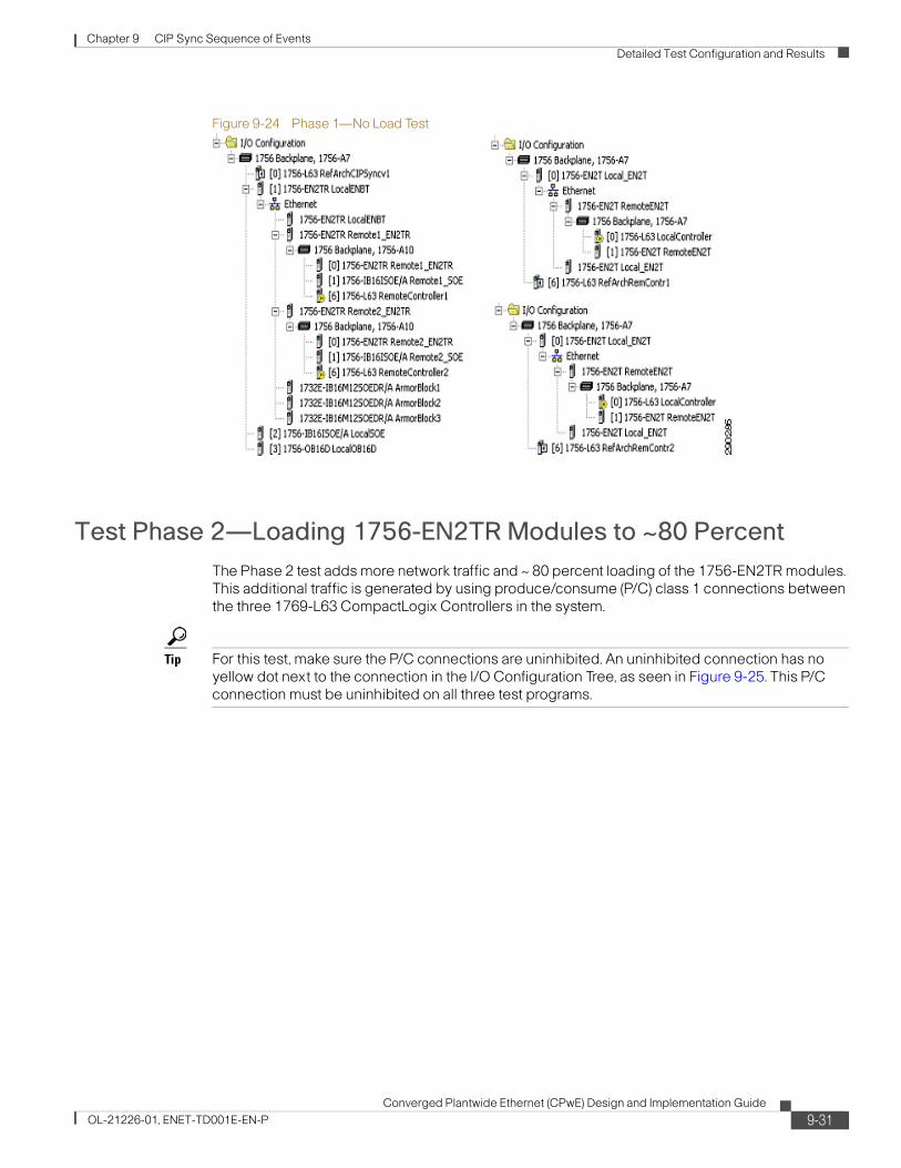
Chapter 9 CIP Sync Sequence of Events Detailed Test Configuration and Results
Figure 9-24 Phase 1—No Load Test
Test Phase 2—Loading 1756-EN2TR Modules to ~80 PercentThe Phase 2 test adds more network traffic and ~ 80 percent loading of the 1756-EN2TR modules. This additional traffic is generated by using produce/consume (P/C) class 1 connections between the three 1769-L63 CompactLogix Controllers in the system.
Tip For this test, make sure the P/C connections are uninhibited. An uninhibited connection has no yellow dot next to the connection in the I/O Configuration Tree, as seen in Figure 9-25. This P/C connection must be uninhibited on all three test programs.
9-31Converged Plantwide Ethernet (CPwE) Design and Implementation Guide
OL-21226-01, ENET-TD001E-EN-P

Chapter 9 CIP Sync Sequence of Events Detailed Test Configuration and Results
Figure 9-25 Loading 1756-EN2TR Modules to ~80 Percent
View the 1756-EN2TR module CPU utilization by typing the 1756-EN2TR IP address into your browser and clicking on the Diagnostic Overview page. Figure 9-26 shows the theoretical and actual performance data. The theoretical data describes how the 1756-EN2TR module should perform based on the RSLoigx5000 software configuration. The actual data reflects the performance of the 1756-EN2TR module.
Figure 9-26 CPU Utilization
As an example, the theoretical I/O comms. utilization performance is at 96.9 percent, but the actual performance is 59.7 percent. The theoretical I/O packets per second are 22536, but the actual performance is 14354. The 1756-EN2TR module is designed to scale back its performance to avoid running out of CPU resources.
9-32Converged Plantwide Ethernet (CPwE) Design and Implementation Guide
OL-21226-01, ENET-TD001E-EN-P

Chapter 9 CIP Sync Sequence of Events Detailed Test Configuration and Results
Test Phase 3—Loading Network Bandwidth by Using the Ixia PCThe Phase 3 test adds more unicast and multicast traffic to the network by using the Ixia traffic generator. Two ports are used on the Ixia box. Ixia traffic flows one way, from Port 4 (Ixia IN) to Port 3 (Ixia OUT). Ixia traffic is placed in the flow of CIP Sync (PTP) traffic, simulating a worst-case scenario.
Three traffic streams are used in the tests. Table 9-5 shows the configuration of these traffic streams.
Table 9-5 Traffic Stream Configuration
Traffic Pattern Ixia Port Traffic Type Packet Size
Traffic Stream Rate (pps)
% of 100 MBps Full Duplex Capacity
1 1 IPv4 TCP/IP—DSCP 27—Class 3 Variable
Min. 64 Bytes
Max. 1510 Bytes
1000 20%
2 IPv4 UDP/IP—DSCP 43 (12 Direct I/O @ 2 msec RPI)
96 Bytes 12000
2 IPv4 UDP/IP- DSCP 47— (12 Safety IO @ 2 msec RPI)
96 Bytes 12000
2 IPv4 UDP/IP-DSCP 55-
(10 CIP Motion Axes @ 4 msec CUR)
260 Bytes 5000
2 1 IPv4 TCP/IP—DSCP 27—Class 3 Variable
Min. 64 Bytes
Max. 1510 Bytes
2000 40%
2 IPv4 UDP/IP—DSCP 43
(25 Direct IO @ 2 msec RPI)
96 Bytes 25000
2 IPv4 UDP/IP- DSCP 47
(25 Safety IO @ 2 msec RPI)
96 Bytes 25000
2 IPv4 UDP/IP- DSCP 55-
(30 CIP Motion Axes @ 4 msec CUR)
260 Bytes 15000
3 1 IPv4 TCP/IP—DSCP 27—Class 3 Variable
Min. 64 Bytes
Max. 1510 Bytes
3000 60%
2 IPv4 UDP/IP—DSCP 43
(40 Direct IO @ 2 msec RPI)
96 Bytes 40000
2 IPv4 UDP/IP- DSCP 47
(40 Safety IO @ 2 msec RPI)
96 Bytes 40000
2 IPv4 UDP/IP- DSCP 55
(50 CIP Motion Axes @ 4 msec CUR)
260 Bytes 25000
9-33Converged Plantwide Ethernet (CPwE) Design and Implementation Guide
OL-21226-01, ENET-TD001E-EN-P

Chapter 9 CIP Sync Sequence of Events Detailed Test Configuration and Results
Tests PerformedThe following tests are performed for each architecture:
• Test 1—Test @ nominal traffic load (no traffic loading)
• Test 2—Test @ minimal traffic load (1756-EN2TR loaded ~80 percent)
• Test 3—Test @ 1756-EN2TR loading ~80 percent and 20 percent Ixia (mixed) traffic load
• Test 4—Test @ 1756-EN2TR loading ~80 percent and 40 percent Ixia (mixed) traffic load
• Test 5—Test @ 1756-EN2TR loading ~80 percent and 60 percent Ixia (mixed) traffic load
• Test 6—Test @ 1756-EN2TR loading ~80 percent and 20 percent Ixia (1500-byte) traffic load
• Test 7—Test @ 1756-EN2TR loading ~80 percent and 40 percent Ixia (1500-byte) traffic load
• Test 8—Test @ 1756-EN2TR loading ~80 percent and 60 percent Ixia (1500-byte) traffic load
Detailed Test ResultsThis section provides detailed test results.
Architecture 1—Star Topology (Using Stratix Switches)
Figure 9-27 shows a diagram of the star topology.
9-34Converged Plantwide Ethernet (CPwE) Design and Implementation Guide
OL-21226-01, ENET-TD001E-EN-P

Chapter 9 CIP Sync Sequence of Events Detailed Test Configuration and Results
Figure 9-27 Star Topology Using the Stratix 8000 Switch with Transparent Clock
In this architecture, all devices were initially connected to a Stratix 8000 switch in a star topology. The Stratix 8000 switch was tested in three PTP modes: transparent, boundary, and forward clock with IGMP and QoS enabled. Subsequent testing was conducted using the Stratix 6000 switch with IGMP enabled, and the Stratix 2000 unmanaged switch. Ixia traffic flows into the Ethernet port of the 1756-EN2TR module in local chassis 1 and exits out the 1732E-IB16M12SOEDR module 3 Ethernet port.
Note The SOE timestamping data chart shown in the following pages shows data collected with a Stratix 8000 switch configured for transparent clock.
2916
25
EN2TR
L6X
SOE
DOUT
EN2TR
SOE L
6X
1732E-IB16M12SOEDR
Armor Block I/O #3(F)
1732E-IB16M12SOEDR
Armor Block I/O #1(D)
Stratix 8000 #1
S
1732E-IB16M12SOEDR
Armor Block I/O #2(E)
SS
EN2TR
SOE L
6X
IXIA PC 1OUT
IXIA PC 1IN
Programming Terminal PanelView Plus
ControlLogixLocal Chassis #1
(A)
ControlLogixRemote Chassis #2
(B)
ControlLogixRemote Chassis #3
(C)
SS
SGM
M
M MS S S S S
9-35Converged Plantwide Ethernet (CPwE) Design and Implementation Guide
OL-21226-01, ENET-TD001E-EN-P

Chapter 9 CIP Sync Sequence of Events Detailed Test Configuration and Results
Figure 9-28 Star Topology—SOE Timestamp Test 1 Results Using the Stratix 8000 Switch with Transparent Clock(A to B)
Figure 9-29 Star Topology—SOE Timestamp Test 3 Results Using the Stratix 8000 Switch with Transparent Clock(A to B)
9-36Converged Plantwide Ethernet (CPwE) Design and Implementation Guide
OL-21226-01, ENET-TD001E-EN-P

Chapter 9 CIP Sync Sequence of Events Detailed Test Configuration and Results
Figure 9-30 Star Topology—SOE Timestamp Test 6 Results Using the Stratix 8000 with Forward Clock (A to B)
Table 9-6 Phase 1 Star Topology—SOE Timestamp Data Results Using Different Types of Stratix Switches (A to B)
Test Number Test Revisions Min Max Avg.
Test 1 (No Load) Stratix 8000 (transparent clock) 0 μs 64 μs 8.64 μs
Stratix 8000 (boundary clock) 0 μs 58 μs 8.47 μs
Stratix 8000 (forward clock) 0 μs 62 μs 8.48 μs
Stratix 6000 (IGMP enabled) 0 μs 61 μs 8.47 μs
Stratix 2000 (unmanaged switch)
0 μs 63 μs 8.49 μs
Test 2 (1756-EN2TR ~80% Loaded)
Stratix 8000 (transparent clock) 0 μs 61 μs 8.44 μs
Stratix 8000 (boundary clock) 0 μs 66 μs 8.47 μs
Stratix 8000 (forward clock) 0 μs 59 μs 8.47 μs
Stratix 6000 (IGMP enabled) 0 μs 64 μs 8.45 μs
Stratix 2000 (unmanaged switch)
0 μs 65 μs 8.48 μs
Test 3 (1756-EN2TR ~80% and
20% Mixed)
Stratix 8000 (transparent clock) 0 μs 63 μs 8.43 μs
Stratix 8000 (boundary clock) 0 μs 63 μs 8.83 μs
Stratix 8000 (forward clock) 0 μs 59 μs 8.44 μs
Stratix 6000 (IGMP enabled) 0 μs 59 μs 8.46 μs
Stratix 2000 (unmanaged switch)
0 μs 63 μs 8.49 μs
Test 4 (1756-EN2TR ~80% and 40% Mixed)
Stratix 8000 (transparent clock) 0 μs 68 μs 8.48 μs
Stratix 8000 (boundary clock) 0 μs 63 μs 8.46 μs
Stratix 8000 (forward clock) 0 μs 62 μs 8.46 μs
Stratix 6000 (IGMP enabled) 0 μs 60 μs 8.47μs
Stratix 2000 (unmanaged switch)
0 μs 58 μs 8.53 μs
9-37Converged Plantwide Ethernet (CPwE) Design and Implementation Guide
OL-21226-01, ENET-TD001E-EN-P

Chapter 9 CIP Sync Sequence of Events Detailed Test Configuration and Results
Test 5 (1756-EN2TR ~80% and
60% Mixed)
Stratix 8000 (transparent clock) 0 μs 60 μs 8.40 μs
Stratix 8000 (boundary clock) 0 μs 60 μs 8.50 μs
Stratix 8000 (forward clock) 0 μs 61 μs 8.55 μs
Stratix 6000 (IGMP enabled) 0 μs 66 μs 8.71 μs
Stratix 2000 (unmanaged switch)
0 μs 64 μs 8.49 μs
Test 6 (1756-EN2TR ~80% and
20% 1500)
Stratix 8000 (transparent clock) 0 μs 60 μs 8.43 μs
Stratix 8000 (boundary clock) 0 μs 61 μs 8.48 μs
Stratix 8000 (forward clock) 0 μs 62 μs 8.54 μs
Stratix 6000 (IGMP enabled) 0 μs 61 μs 8.66 μs
Stratix 2000 (unmanaged switch)
0 μs 62 μs 8.57 μs
Test 7 (1756-EN2TR ~80% and 40% 1500)
Stratix 8000 (transparent clock) 0 μs 65 μs 8.44 μs
Stratix 8000 (boundary clock) 0 μs 60 μs 8.48 μs
Stratix 8000 (forward CLOCK) 0 μs 62 μs 8.52 μs
Stratix 6000 (IGMP enabled) 0 μs 68 μs 8.87 μs
Stratix 2000 (unmanaged switch)
0 μs 60 μs 8.71 μs
Test 8 (1756-EN2TR ~80% and
60% 1500)
Stratix 8000 (transparent clock) 0 μs 62 μs 8.46 μs
Stratix 8000 (boundary clock) 0 μs 65 μs 8.45 μs
Stratix 8000 (forward clock) 0 μs 64 μs 8.67 μs
Stratix 6000 (IGMP enabled) 0 μs 77 μs 9.25 μs
Stratix 2000 (unmanaged switch)
0 μs 61 μs 8.81 μs
Table 9-6 Phase 1 Star Topology—SOE Timestamp Data Results Using Different Types of Stratix Switches (A to B)
Test Number Test Revisions Min Max Avg.
9-38Converged Plantwide Ethernet (CPwE) Design and Implementation Guide
OL-21226-01, ENET-TD001E-EN-P

Chapter 9 CIP Sync Sequence of Events Detailed Test Configuration and Results
Figure 9-31 Star Topology—SOE Timestamp Test 1 Results Using the Stratix 8000 Switch with Transparent Clock(A to D)
Figure 9-32 Star Topology—SOE Timestamp Test 3 Results Using the Stratix 8000 with Transparent Clock (A to D)
9-39Converged Plantwide Ethernet (CPwE) Design and Implementation Guide
OL-21226-01, ENET-TD001E-EN-P

Chapter 9 CIP Sync Sequence of Events Detailed Test Configuration and Results
Figure 9-33 Star Topology—SOE Timestamp Test 6 Results Using the Stratix 8000 with Forward Clock (A to D)
Table 9-7 Star Topology—SOE Timestamp Data Results Using Different Types of Stratix Switches (A to D)
Test Number Test Revisions Min Max Avg.
Test 1 (No Load) Stratix 8000 (transparent clock) 0 μs 50 μs 6.51 μs
Stratix 8000 (boundary clock) 0 μs 51 μs 6.53 μs
Stratix 8000 (forward clock) 0 μs 51 μs 6.55 μs
Stratix 6000 (IGMP enabled) 0 μs 51 μs 6.61 μs
Stratix 2000 (unmanaged switch)
0 μs 61 μs 6.55 μs
Test 2 (1756-EN2TR ~80% Loaded)
Stratix 8000 (transparent clock) 0 μs 51 μs 6.55 μs
Stratix 8000 (boundary clock) 0 μs 56 μs 6.58 μs
Stratix 8000 (forward clock) 0 μs 50 μs 6.74 μs
Stratix 6000 (IGMP enabled) 0 μs 49 μs 6.80 μs
Stratix 2000 (unmanaged switch)
0 μs 49 μs 6.84 μs
Test 3 (1756-EN2TR ~80% and
20% Mixed)
Stratix 8000 (transparent clock) 0 μs 54 μs 6.57 μs
Stratix 8000 (boundary clock) 0 μs 53 μs 6.62 μs
Stratix 8000 (forward clock) 0 μs 54 μs 6.90 μs
Stratix 6000 (IGMP enabled) 0 μs 52 μs 6.89 μs
Stratix 2000 (unmanaged switch)
0 μs 59 μs 7.03 μs
Test 4 (1756-EN2TR ~80% and 40% Mixed)
Stratix 8000 (transparent clock) 0 μs 54 μs 6.61 μs
Stratix 8000 (boundary clock) 0 μs 51 μs 6.61 μs
Stratix 8000 (forward CLOCK) 0 μs 49 μs 6.86 μs
Stratix 6000 (IGMP enabled) 0 μs 53 μs 6.83 μs
Stratix 2000 (unmanaged switch)
0 μs 49 μs 6.98 μs
9-40Converged Plantwide Ethernet (CPwE) Design and Implementation Guide
OL-21226-01, ENET-TD001E-EN-P

Chapter 9 CIP Sync Sequence of Events Detailed Test Configuration and Results
Test 5 (1756-EN2TR ~80% and
60% Mixed)
Stratix 8000 (transparent clock) 0 μs 49 μs 6.55 μs
Stratix 8000 (boundary clock) 0 μs 52 μs 6.66 μs
Stratix 8000 (forward clock) 0 μs 52 μs 6.98 μs
Stratix 6000 (IGMP enabled) 0 μs 51 μs 6.78 μs
Stratix 2000 (unmanaged switch)
0 μs 48 μs 6.83 μs
Test 6 (1756-EN2TR ~80% and
20% 1500)
Stratix 8000 (transparent clock) 0 μs 50 μs 6.59 μs
Stratix 8000 (boundary clock) 0 μs 51 μs 6.61 μs
Stratix 8000 (forward clock) 0 μs 50 μs 6.74 μs
Stratix 6000 (IGMP enabled) 0 μs 51 μs 6.80 μs
Stratix 2000 (unmanaged switch)
0 μs 48 μs 6.95 μs
Test 7 (1756-EN2TR ~80% and 40% 1500)
Stratix 8000 (transparent clock) 0 μs 54 μs 6.59 μs
Stratix 8000 (boundary clock) 0 μs 49 μs 6.63 μs
Stratix 8000 (forward clock) 0 μs 54 μs 6.66 μs
Stratix 6000 (IGMP enabled) 0 μs 50 μs 6.89 μs
Stratix 2000 (unmanaged switch)
0 μs 52 μs 6.97 μs
Test 8 (1756-EN2TR ~80% and
60% 1500)
Stratix 8000 (transparent clock) 0 μs 53 μs 6.59 μs
Stratix 8000 (boundary clock) 0 μs 43 μs 6.59 μs
Stratix 8000 (forward clock) 0 μs 54 μs 6.72 μs
Stratix 6000 (IGMP enabled) 0 μs 46 μs 6.89 μs
Stratix 2000 (unmanaged switch)
0 μs 67 μs 7.20 μs
Table 9-7 Star Topology—SOE Timestamp Data Results Using Different Types of Stratix Switches (A to D)
Test Number Test Revisions Min Max Avg.
9-41Converged Plantwide Ethernet (CPwE) Design and Implementation Guide
OL-21226-01, ENET-TD001E-EN-P

Chapter 9 CIP Sync Sequence of Events Detailed Test Configuration and Results
Figure 9-34 Star Topology—SOE Timestamp Test 1 Results Using the Stratix 8000 with Transparent Clock (A to F)
Figure 9-35 Star Topology—SOE Timestamp Test 3 Results Using the Stratix 8000 with Transparent Clock (A to F)
9-42Converged Plantwide Ethernet (CPwE) Design and Implementation Guide
OL-21226-01, ENET-TD001E-EN-P

Chapter 9 CIP Sync Sequence of Events Detailed Test Configuration and Results
Figure 9-36 Star Topology—SOE Timestamp Test 6 Results Using the Stratix 8000 with Forward Clock (A to F)
Table 9-8 Star Topology—SOE Timestamp Data Results Using Different Types of Stratix Switches (A to F)
Test Number Test Revisions Min Max Avg.
Test 1 (No Load) Stratix 8000 (transparent clock) 0 μs 49μs 6.67 μs
Stratix 8000 (boundary clock) 0 μs 50 μs 6.69 μs
Stratix 8000 (forward clock) 0 μs 51 μs 6.69 μs
Stratix 6000 (IGMP enabled) 0 μs 51 μs 6.74 μs
Stratix 2000 (unmanaged switch)
0 μs 60μs 6.69 μs
Test 2 (1756-EN2TR ~80% Loaded)
Stratix 8000 (transparent clock) 0 μs 50 μs 6.72 μs
Stratix 8000 (boundary clock) 0 μs 55 μs 6.74μs
Stratix 8000 (forward clock) 0 μs 50 μs 6.92 μs
Stratix 6000 (IGMP enabled) 0 μs 47 μs 7.15 μs
Stratix 2000 (unmanaged switch)
0 μs 48 μs 7.15 μs
Test 3 (1756-EN2TR ~80% and
20% Mixed)
Stratix 8000 (transparent clock) 0 μs 54 μs 6.73 μs
Stratix 8000 (boundary clock) 0 μs 52 μs 6.79 μs
Stratix 8000 (forward clock) 0 μs 62 μs 7.82 μs
Stratix 6000 (IGMP enabled) 0 μs 55 μs 7.75 μs
Stratix 2000 (unmanaged switch)
0 μs 62 μs 7.89 μs
9-43Converged Plantwide Ethernet (CPwE) Design and Implementation Guide
OL-21226-01, ENET-TD001E-EN-P

Chapter 9 CIP Sync Sequence of Events Detailed Test Configuration and Results
Test 4 (1756-EN2TR ~80% and 40% Mixed)
Stratix 8000 (transparent clock) 0 μs 53 μs 6.77 μs
Stratix 8000 (boundary clock) 0 μs 51 μs 6.77 μs
Stratix 8000 (forward clock) 0 μs 58 μs 8.24 μs
Stratix 6000 (IGMP enabled) 0 μs 63 μs 8.01 μs
Stratix 2000 (unmanaged switch)
0 μs 69 μs 8.19 μs
Test 5 (1756-EN2TR ~80% and
60% Mixed)
Stratix 8000 (transparent clock) 0 μs 48 μs 6.72 μs
Stratix 8000 (boundary clock) 0 μs 51 μs 6.82 μs
Stratix 8000 (forward clock) 0 μs 61 μs 7.64 μs
Stratix 6000 (IGMP enabled) 0 μs 59 μs 7.53 μs
Stratix 2000 (unmanaged switch)
0 μs 70 μs 8.02 μs
Test 6 (1756-EN2TR ~80% and
20% 1500)
Stratix 8000 (transparent clock) 0 μs 50 μs 6.75 μs
Stratix 8000 (boundary clock) 0 μs 51 μs 6.77 μs
Stratix 8000 (forward clock) 0 μs 143 μs 36.96 μs
Stratix 6000 (IGMP enabled) 0 μs 149 μs 39.06 μs
Stratix 2000 (unmanaged switch)
0 μs 145 μs 40.14 μs
Test 7 (1756-EN2TR ~80% and 40% 1500)
Stratix 8000 (transparent clock) 0 μs 54 μs 6.75 μs
Stratix 8000 (boundary clock) 0 μs 49 μs 6.77 μs
Stratix 8000 (forward clock) 0 μs 124 μs 49.47 μs
Stratix 6000 (IGMP enabled) 0 μs 128 μs 51.57 μs
Stratix 2000 (unmanaged switch)
0 μs 137 μs 51.41 μs
Test 8 (1756-EN2TR ~80% and
60% 1500)
Stratix 8000 (transparent clock) 0 μs 53 μs 6.79 μs
Stratix 8000 (boundary clock) 0 μs 45 μs 6.76 μs
Stratix 8000 (forward clock) 0 μs 117 μs 46.23 μs
Stratix 6000 (IGMP enabled) 0 μs 116 μs 48.10 μs
Stratix 2000 (unmanaged switch)
0 μs 137 μs 49.37 μs
Table 9-8 Star Topology—SOE Timestamp Data Results Using Different Types of Stratix Switches (A to F)
Test Number Test Revisions Min Max Avg.
9-44Converged Plantwide Ethernet (CPwE) Design and Implementation Guide
OL-21226-01, ENET-TD001E-EN-P

Chapter 9 CIP Sync Sequence of Events Detailed Test Configuration and Results
Architecture 2—Linear Topology (Using Devices With Embedded Dual-Port Ethernet Technology)
In the linear topology shown in Figure 9-37, all devices are connected in a daisy-chain fashion via the embedded dual Ethernet switch ports of each device. This embedded switch is a managed switch configured in transparent clock with QoS and IGMP enabled. Ixia traffic flows into the 1756-EN2TR module Ethernet port in local chassis 1 through the entire network and exits out the 1783- ETAP module 1 Ethernet port.
Figure 9-37 Linear Topology Using Embedded Dual-Port Ethernet Switch Devices with Transparent Clock
Architecture 3—Ring Topology (Device Level Ring Technology)
In the ring topology shown in Figure 9-38, all devices are connected in a device level ring via the embedded dual Ethernet switch ports of each device. This embedded switch is a managed switch configured in transparent Clock with QoS and IGMP enabled. Ixia traffic flows into the 1756-EN2TR module 1 Ethernet port in local chassis 1 through half of the network and exits out the 1783-ETAP module 4 Ethernet port.
2916
20
EN2TR
L6X
SOE
DOUT
EN2TR
SOE L
6X
1732E-IB16M12SOEDR
Armor Block I/O #3(F)
1732E-IB16M12SOEDR
Armor Block I/O #1(D)
1783-ETAP #21783-ETAP #1
S
1732E-IB16M12SOEDR
Armor Block I/O #2(E)
SS
EN2TR
SOE L
6X
IXIA PC 1OUT
IXIA PC 1IN
PanelViewPlus
ProgrammingTerminal
SS
ControlLogixLocal Chassis #1
(A)
ControlLogixRemote Chassis #2
(B)
ControlLogixRemote Chassis #3
(C)
SGM
M
M MS S S S S
9-45Converged Plantwide Ethernet (CPwE) Design and Implementation Guide
OL-21226-01, ENET-TD001E-EN-P
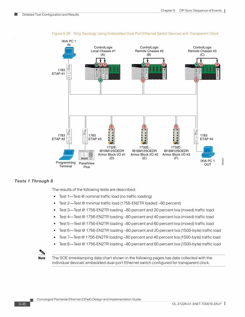
Chapter 9 CIP Sync Sequence of Events Detailed Test Configuration and Results
Figure 9-38 Ring Topology Using Embedded Dual-Port Ethernet Switch Devices with Transparent Clock.
Tests 1 Through 8
The results of the following tests are described:
• Test 1—Test @ nominal traffic load (no traffic loading)
• Test 2—Test @ minimal traffic load (1756-EN2TR loaded ~80 percent)
• Test 3—Test @ 1756-EN2TR loading ~80 percent and 20 percent Ixia (mixed) traffic load
• Test 4—Test @ 1756-EN2TR loading ~80 percent and 40 percent Ixia (mixed) traffic load
• Test 5—Test @ 1756-EN2TR loading ~80 percent and 60 percent Ixia (mixed) traffic load
• Test 6—Test @ 1756-EN2TR loading ~80 percent and 20 percent Ixia (1500-byte) traffic load
• Test 7—Test @ 1756-EN2TR loading ~80 percent and 40 percent Ixia (1500-byte) traffic load
• Test 8—Test @ 1756-EN2TR loading ~80 percent and 60 percent Ixia (1500-byte) traffic load
Note The SOE timestamping data chart shown in the following pages has data collected with the individual devices’ embedded dual-port Ethernet switch configured for transparent clock.
2916
21
EN2TR
L6X
SOE
DOUT
EN2TR
SOE L
6X
1732E-IB16M12SOEDR
Armor Block I/O #3(F)
1732E-IB16M12SOEDR
Armor Block I/O #1(D)
1783ETAP #2
1783ETAP #1
1783ETAP #3
1783ETAP #4
S
1732E-IB16M12SOEDR
Armor Block I/O #2(E)
SS
EN2TR
SOE L
6X
IXIA PC 1IN
PanelViewPlus
ProgrammingTerminal
IXIA PC 1OUT
T
SS
ControlLogixLocal Chassis #1
(A)
ControlLogixRemote Chassis #2
(B)
ControlLogixRemote Chassis #3
(C)
SGM
M
M MS S S S S
9-46Converged Plantwide Ethernet (CPwE) Design and Implementation Guide
OL-21226-01, ENET-TD001E-EN-P

Chapter 9 CIP Sync Sequence of Events Detailed Test Configuration and Results
Figure 9-39 Linear Topology—SOE Timestamp Test 1 Results Using Embedded Dual-Port Ethernet Switch Devices with Transparent Clock (A to C)
Table 9-9 Linear Topology—SOE Timestamp Data Results Using the Embedded Dual-Port Ethernet Switch (A to C)
Test Number Test Revisions Min Max Avg.
Test 1 (No Load) Architecture 2 (Linear Topology)
Architecture 3 (Ring Topology)
0 μs
0 μs
65 μs
66 μs
8.45 μs
8.48 μs
Test 2 (1756-EN2TR ~80% Loaded) Architecture 2 (Linear Topology)
Architecture 3 (Ring Topology)
0 μs
0 μs
60 μs
59 μs
8.45 μs
8.49 μs
Test 3 (1756- EN2TR ~80% and 20% Mixed) Architecture 2 (Linear Topology)
Architecture 3 (Ring Topology)
0 μs
0 μs
65 μs
64 μs
8.42 μs
8.47 μs
Test 4 (1756- EN2TR ~80% and 40% Mixed) Architecture 2 (Linear Topology)
Architecture 3 (Ring Topology)
0 μs
0 μs
63 μs
65 μs
8.45 μs
8.48 μs
Test 5 (1756- EN2TR ~80% and 60% Mixed) Architecture 2 (Linear Topology)
Architecture 3 (Ring Topology)
0 μs
0 μs
58 μs
60 μs
8.45 μs
8.49 μs
Test 6 (1756- EN2TR ~80% and 20% 1500) Architecture 2 (Linear Topology)
Architecture 3 (Ring Topology)
0 μs
0 μs
62 μs
62 μs
8.48 μs
8.43 μs
Test 7 (1756- EN2TR ~80% and 40% 1500) Architecture 2 (Linear Topology)
Architecture 3 (Ring Topology)
0 μs
0 μs
65 μs
63 μs
8.50μs
8.48 μs
Test 8 (1756- EN2TR ~80% and 60% 1500) Architecture 2 (Linear Topology)
Architecture 3 (Ring Topology)
0 μs
0 μs
61μs
63 μs
8.46 μs
8.48 μs
9-47Converged Plantwide Ethernet (CPwE) Design and Implementation Guide
OL-21226-01, ENET-TD001E-EN-P
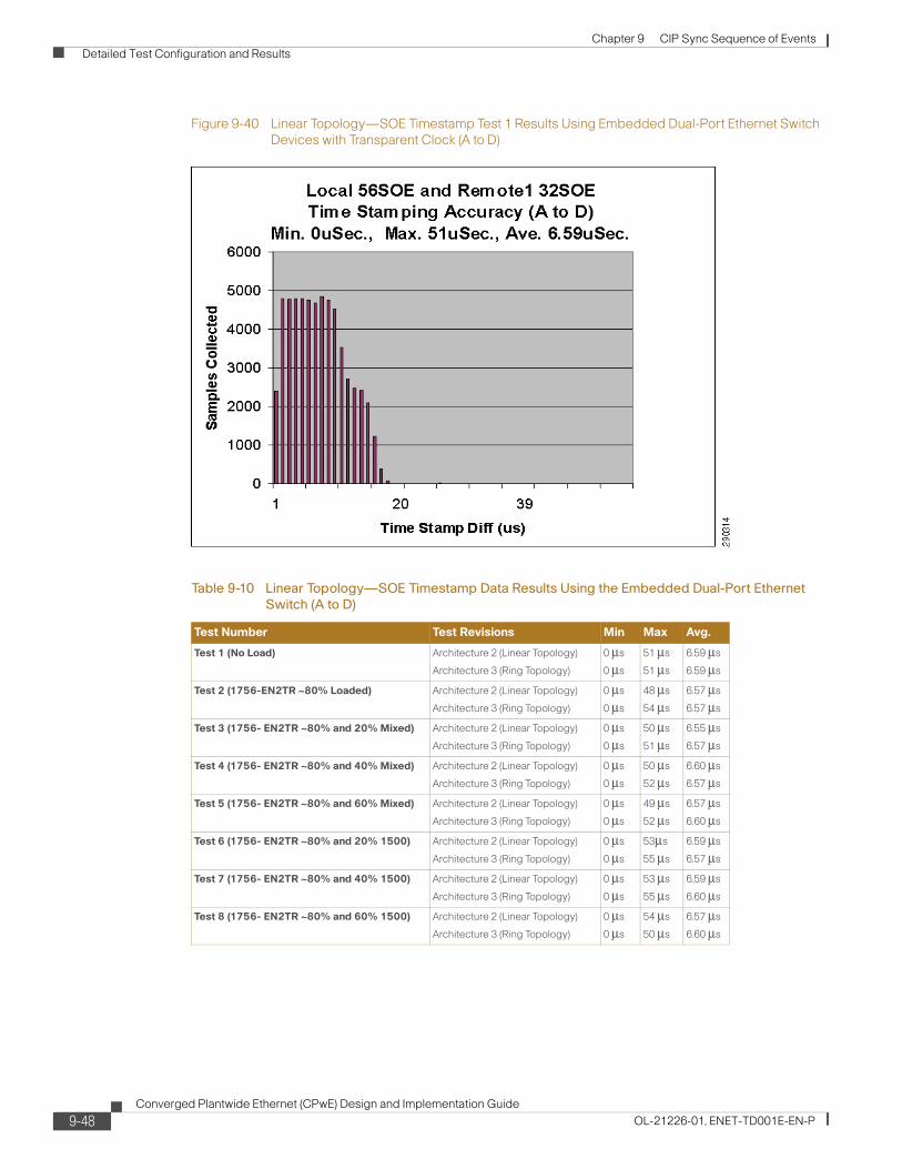
Chapter 9 CIP Sync Sequence of Events Detailed Test Configuration and Results
Figure 9-40 Linear Topology—SOE Timestamp Test 1 Results Using Embedded Dual-Port Ethernet Switch Devices with Transparent Clock (A to D)
Table 9-10 Linear Topology—SOE Timestamp Data Results Using the Embedded Dual-Port Ethernet Switch (A to D)
Test Number Test Revisions Min Max Avg.
Test 1 (No Load) Architecture 2 (Linear Topology)
Architecture 3 (Ring Topology)
0 μs
0 μs
51 μs
51 μs
6.59 μs
6.59 μs
Test 2 (1756-EN2TR ~80% Loaded) Architecture 2 (Linear Topology)
Architecture 3 (Ring Topology)
0 μs
0 μs
48 μs
54 μs
6.57 μs
6.57 μs
Test 3 (1756- EN2TR ~80% and 20% Mixed) Architecture 2 (Linear Topology)
Architecture 3 (Ring Topology)
0 μs
0 μs
50 μs
51 μs
6.55 μs
6.57 μs
Test 4 (1756- EN2TR ~80% and 40% Mixed) Architecture 2 (Linear Topology)
Architecture 3 (Ring Topology)
0 μs
0 μs
50 μs
52 μs
6.60 μs
6.57 μs
Test 5 (1756- EN2TR ~80% and 60% Mixed) Architecture 2 (Linear Topology)
Architecture 3 (Ring Topology)
0 μs
0 μs
49 μs
52 μs
6.57 μs
6.60 μs
Test 6 (1756- EN2TR ~80% and 20% 1500) Architecture 2 (Linear Topology)
Architecture 3 (Ring Topology)
0 μs
0 μs
53μs
55 μs
6.59 μs
6.57 μs
Test 7 (1756- EN2TR ~80% and 40% 1500) Architecture 2 (Linear Topology)
Architecture 3 (Ring Topology)
0 μs
0 μs
53 μs
55 μs
6.59 μs
6.60 μs
Test 8 (1756- EN2TR ~80% and 60% 1500) Architecture 2 (Linear Topology)
Architecture 3 (Ring Topology)
0 μs
0 μs
54 μs
50 μs
6.57 μs
6.60 μs
9-48Converged Plantwide Ethernet (CPwE) Design and Implementation Guide
OL-21226-01, ENET-TD001E-EN-P

Chapter 9 CIP Sync Sequence of Events Detailed Test Configuration and Results
Architecture 4—Multiple Star Topology (Separated Network Segments Using the 1756-EN2T Modules in Boundary Clock Mode)
In the multiple star topology shown in Figure 9-41, all devices are initially connected to a Stratix 8000 switch in a multiple star topology. The Stratix 8000 switch was tested in two PTP modes: transparent and forward clock with QoS and IGMP enabled. Subsequent testing was conducted using the Stratix 6000 switch with IGMP enabled, as well as the Stratix 2000 unmanaged switch. Ixia traffic flows into the 1756-EN2TR module 1 Ethernet port in local chassis 1 and exits out the 1732E-IB16M12SOEDR module 1 Ethernet port.
Figure 9-41 Multiple Star Topology Segmented by 1756-EN2T Modules with Boundary Clock and Stratix 8000 Switch with Transparent Clock
Note The SOE timestamping data chart shown in the following pages has data collected with a Stratix 8000 configured for transparent clock.
2916
22
Stratix8000
#1
Stratix8000#2
Stratix8000
#3
BoundaryClock #1
1732E-IB16M12SOEDR
Armor Block I/O #1(E)
S
IXIA PC 1OUT
IXIA PC 1IN
PanelViewPlus
ControlLogixLocal Chassis #1
(A)
ControlLogixRemote Chassis #2
(B)
Segment 1
Segment 2
Segment 3ControlLogix
Remote Chassis #3(C)
ControlLogixRemote Chassis #4
(D)
ProgrammingTerminal
EN2TR
L6X
SOE
DOUT
EN2TR
SOE L
6X
EN2T
EN2TR
SOE L
6X
EN2T
EN2TR
SOE L
6X
EN2T
PanelViewPlus
S M
BoundaryClock #2
S
S
M
1732E-IB16M12SOEDR
Armor Block I/O #2(F)
S
PanelViewPlus
1732E-IB16M12SOEDR
Armor Block I/O #3(G)
S
SGM
M
S
M S S S
M S S S
M S S S
9-49Converged Plantwide Ethernet (CPwE) Design and Implementation Guide
OL-21226-01, ENET-TD001E-EN-P
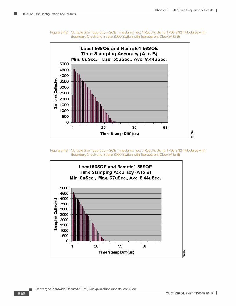
Chapter 9 CIP Sync Sequence of Events Detailed Test Configuration and Results
Figure 9-42 Multiple Star Topology—SOE Timestamp Test 1 Results Using 1756-EN2T Modules with Boundary Clock and Stratix 8000 Switch with Transparent Clock (A to B)
Figure 9-43 Multiple Star Topology—SOE Timestamp Test 3 Results Using 1756-EN2T Modules with Boundary Clock and Stratix 8000 Switch with Transparent Clock (A to B)
9-50Converged Plantwide Ethernet (CPwE) Design and Implementation Guide
OL-21226-01, ENET-TD001E-EN-P

Chapter 9 CIP Sync Sequence of Events Detailed Test Configuration and Results
Figure 9-44 Multiple Star Topology—SOE Timestamp Test 6 Results using 1756-EN2T Modules with Boundary Clock and Stratix 8000 Switches with Forward Clock (A to B)
Table 9-11 Multiple Star Topology—SOE Timestamp Data Results Using Different Types of Stratix 8000 Switches (A to B)
Test Number Test Revisions Min Max Avg.
Test 1 (No Load) Stratix 8000 (transparent clock) 0 μs 55 μs 8.44 μs
Stratix 8000 (forward Clock) 0 μs 68 μs 8.46 μs
Stratix 6000 (IGMP enabled) 0 μs 62 μs 8.46 μs
Stratix 2000 (unmanaged switch)
0 μs 63 μs 8.48 μs
Test 2 (1756-EN2TR ~80% loaded)
Stratix 8000 (transparent clock) 0 μs 66 μs 8.44 μs
Stratix 8000 (forward clock) 0 μs 63 μs 8.46 μs
Stratix 8000 (IGMP enabled) 0 μs 59 μs 8.49 μs
Stratix 2000 (unmanaged switch)
0 μs 60 μs 8.48 μs
Test 3 (1756-EN2TR ~80% and
20% Ixia (Mixed) Traffic Load
Stratix 8000 (transparent clock) 0 μs 67 μs 8.44 μs
Stratix 8000 (forward clock) 0 μs 63 μs 8.47 μs
Stratix 6000 (IGMP enabled) 0 μs 64 μs 8.48 μs
Stratix 2000 (unmanaged switch)
0 μs 62 μs 8.48 μs
Test 4 (1756-EN2TR ~80% and 40% Ixia (Mixed) Traffic Load
Stratix 8000 (transparent clock) 0 μs 61 μs 8.43 μs
Stratix 8000 (forward clock) 0 μs 65 μs 8.45 μs
Stratix 6000 (IGMP enabled) 0 μs 62 μs 8.46 μs
Stratix 2000 (unmanaged switch)
0 μs 62 μs 8.46 μs
9-51Converged Plantwide Ethernet (CPwE) Design and Implementation Guide
OL-21226-01, ENET-TD001E-EN-P

Chapter 9 CIP Sync Sequence of Events Detailed Test Configuration and Results
Figure 9-45 Multiple Star Topology—SOE Timestamp Test 1 Results Using 1756-EN2T Modules with Boundary Clock and Stratix 8000 Switch with Transparent Clock (A to C)
Test 5 (1756-EN2TR ~80% and 60% Ixia (Mixed) Traffic Load
Stratix 8000 (transparent clock) 0 μs 64 μs 8.50 μs
Stratix 8000 (forward clock) 0 μs 58 μs 8.63 μs
Stratix 6000 (IGMP enabled) 0 μs 73 μs 8.64 μs
Stratix 2000 (unmanaged switch)
0 μs 62 μs 8.52 μs
Test 6 (1756-EN2TR ~80% and
20% 1500)
Stratix 8000 (transparent clock) 0 μs 65 μs 8.46 μs
Stratix 8000 (forward clock) 0 μs 68 μs 8.64 μs
Stratix 6000 (IGMP enabled) 0 μs 71 μs 8.62 μs
Stratix 2000 (unmanaged switch)
0 μs 65 μs 8.73 μs
Test 7 (1756-EN2TR ~80% and 40% 1500)
Stratix 8000 (transparent clock) 0 μs 66 μs 8.46 μs
Stratix 8000 (forward clock) 0 μs 62 μs 8.86 μs
Stratix 6000 (IGMP enabled) 0 μs 67 μs 8.76 μs
Stratix 2000 (unmanaged switch)
0 μs 78 μs 8.87 μs
Test 8 (1756-EN2TR ~80% and 60% 1500)
Stratix 8000 (transparent CLOCK)
0 μs 62 μs 8.48 μs
Stratix 8000 (forward clock) 0 μs 82 μs 9.15 μs
Stratix 6000 (IGMP enabled) 0 μs 62 μs 9.12 μs
Stratix 2000 (unmanaged switch)
0 μs 72 μs 9.29 μs
Table 9-11 Multiple Star Topology—SOE Timestamp Data Results Using Different Types of Stratix 8000 Switches (A to B)
Test Number Test Revisions Min Max Avg.
9-52Converged Plantwide Ethernet (CPwE) Design and Implementation Guide
OL-21226-01, ENET-TD001E-EN-P

Chapter 9 CIP Sync Sequence of Events Detailed Test Configuration and Results
Figure 9-46 Multiple Star Topology—SOE Timestamp Test 3 Results using EN2T Modules with Boundary Clock and Stratix 8000 Switch with Transparent Clock (A to C)
Figure 9-47 Multiple Star Topology—SOE Timestamp Test 6 Results using 1756-EN2T Modules with Boundary Clock and Stratix 8000 Switches with Forward Clock (A to C)
9-53Converged Plantwide Ethernet (CPwE) Design and Implementation Guide
OL-21226-01, ENET-TD001E-EN-P

Chapter 9 CIP Sync Sequence of Events Detailed Test Configuration and Results
Table 9-12 Multiple Star Topology—SOE Timestamp Data Results Using Different Types of Stratix 8000 Switches (A to C)
Test Number Test Revisions Min Max Avg.
Test 1 (No Load) Stratix 8000 (transparent clock) 0 μs 61μs 8.42 μs
Stratix 8000 (forward clock) 0 μs 61 μs 8.45 μs
Stratix 6000 (IGMP enabled) 0 μs 63 μs 8.47 μs
Stratix 2000 (unmanaged switch)
0 μs 64 μs 8.47 μs
Test 2 (1756-EN2TR ~80% loaded)
Stratix 8000 (transparent clock) 0 μs 62 μs 8.42 μs
Stratix 8000 (forward clock) 0 μs 64μs 8.45 μs
Stratix 8000 (IGMP enabled) 0 μs 60 μs 8.46 μs
Stratix 2000 (unmanaged switch)
0 μs 67 μs 8.48 μs
Test 3 (1756-EN2TR ~80% and
20% Ixia (Mixed) Traffic Load
Stratix 8000 (transparent clock) 0 μs 63 μs 8.47 μs
Stratix 8000 (forward clock) 0 μs 61 μs 8.44 μs
Stratix 6000 (IGMP enabled) 0 μs 67 μs 8.46 μs
Stratix 2000 (unmanaged switch)
0 μs 62 μs 8.47 μs
Test 4 (1756-EN2TR ~80% and 40% Ixia (Mixed) Traffic Load
Stratix 8000 (transparent clock) 0 μs 65 μs 8.44 μs
Stratix 8000 (forward clock) 0 μs 62 μs 8.45 μs
Stratix 6000 (IGMP enabled) 0 μs 62 μs 8.46 μs
Stratix 2000 (unmanaged switch)
0 μs 61 μs 8.47 μs
Test 5 (1756-EN2TR ~80% and 60% Ixia (Mixed) Traffic Load
Stratix 8000 (transparent clock) 0 μs 62 μs 8.42 μs
Stratix 8000 (forward clock) 0 μs 63 μs 8.62 μs
Stratix 6000 (IGMP enabled) 0 μs 66 μs 8.65 μs
Stratix 2000 (unmanaged switch)
0 μs 64 μs 8.52 μs
Test 6 (1756-EN2TR ~80% and
20% 1500)
Stratix 8000 (transparent clock) 0 μs 59μs 8.44μs
Stratix 8000 (forward clock) 0 μs 82 μs 8.61 μs
Stratix 6000 (IGMP enabled) 0 μs 63 μs 8.64 μs
Stratix 2000 (unmanaged switch)
0 μs 70 μs 8.75 μs
Test 7 (1756-EN2TR ~80% and 40% 1500)
Stratix 8000 (transparent clock) 0 μs 64 μs 8.45 μs
Stratix 8000 (forward clock) 0 μs 66 μs 8.80 μs
Stratix 6000 (IGMP enabled) 0 μs 62 μs 8.78 μs
Stratix 2000 (unmanaged switch)
0 μs 66 μs 8.93 μs
Test 8 (1756-EN2TR ~80% and 60% 1500)
Stratix 8000 (transparent clock) 0 μs 63 μs 8.46 μs
Stratix 8000 (forward clock) 0 μs 64 μs 9.13 μs
Stratix 6000 (IGMP enabled) 0 μs 68 μs 9.10 μs
Stratix 2000 (unmanaged switch)
0 μs 84 μs 9.26 μs
9-54Converged Plantwide Ethernet (CPwE) Design and Implementation Guide
OL-21226-01, ENET-TD001E-EN-P
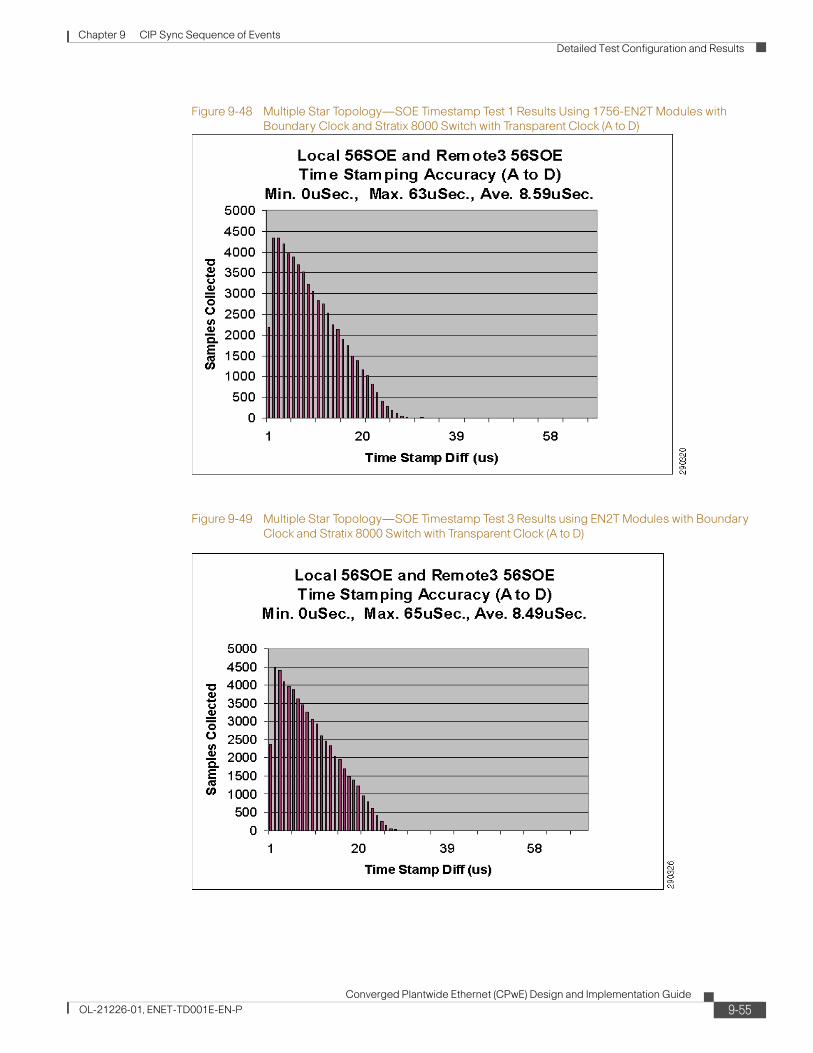
Chapter 9 CIP Sync Sequence of Events Detailed Test Configuration and Results
Figure 9-48 Multiple Star Topology—SOE Timestamp Test 1 Results Using 1756-EN2T Modules with Boundary Clock and Stratix 8000 Switch with Transparent Clock (A to D)
Figure 9-49 Multiple Star Topology—SOE Timestamp Test 3 Results using EN2T Modules with Boundary Clock and Stratix 8000 Switch with Transparent Clock (A to D)
9-55Converged Plantwide Ethernet (CPwE) Design and Implementation Guide
OL-21226-01, ENET-TD001E-EN-P

Chapter 9 CIP Sync Sequence of Events Detailed Test Configuration and Results
Figure 9-50 Multiple Star Topology—SOE Timestamp Test 6 Results using 1756-EN2T Modules with Boundary Clock and Stratix 8000 Switches with Forward Clock (A to D)
Table 9-13 Multiple Star Topology—SOE Timestamp Data Results Using Different Types of Stratix 8000 Switches (A to D)
Test Number Test Revisions Min Max Avg.
Test 1 (No Load) Stratix 8000 (transparent clock) 0 μs 63 μs 8.59 μs
Stratix 8000 (forward clock) 0 μs 64 μs 8.60 μs
Stratix 6000 (IGMP enabled) 0 μs 67 μs 8.62 μs
Stratix 2000 (unmanaged switch)
0 μs 60 μs 8.67 μs
Test 2 (1756-EN2TR ~80% loaded)
Stratix 8000 (transparent clock) 0 μs 65 μs 8.45 μs
Stratix 8000 (forward clock) 0 μs 61μs 8.48 μs
Stratix 8000 (IGMP enabled) 0 μs 61 μs 8.51 μs
Stratix 2000 (unmanaged switch)
0 μs 59 μs 8.54 μs
Test 3 (1756-EN2TR ~80% and
20% Ixia (Mixed) Traffic Load
Stratix 8000 (transparent clock) 0 μs 65 μs 8.49 μs
Stratix 8000 (forward clock) 0 μs 62 μs 8.49 μs
Stratix 6000 (IGMP enabled) 0 μs 67 μs 8.50 μs
Stratix 2000 (unmanaged switch)
0 μs 62 μs 8.52 μs
Test 4 (1756-EN2TR ~80% and 40% Ixia (Mixed) Traffic Load
Stratix 8000 (transparent clock) 0 μs 63 μs 8.50 μs
Stratix 8000 (forward clock) 0 μs 65 μs 8.53 μs
Stratix 6000 (IGMP enabled) 0 μs 68 μs 8.49 μs
Stratix 2000 (unmanaged switch)
0 μs 62 μs 8.51 μs
9-56Converged Plantwide Ethernet (CPwE) Design and Implementation Guide
OL-21226-01, ENET-TD001E-EN-P

Chapter 9 CIP Sync Sequence of Events Detailed Test Configuration and Results
Figure 9-51 Multiple Star Topology—SOE Timestamp Test 1 Results Using 1756-EN2T Modules with Boundary Clock and Stratix 8000 Switch with Transparent Clock (A to E)
Test 5 (1756-EN2TR ~80% and 60% Ixia (Mixed) Traffic Load
Stratix 8000 (transparent clock) 0 μs 67 μs 8.49 μs
Stratix 8000 (forward clock) 0 μs 62 μs 8.69 μs
Stratix 6000 (IGMP enabled) 0 μs 63 μs 8.67 μs
Stratix 2000 (unmanaged switch)
0 μs 65 μs 8.64 μs
Test 6 (1756-EN2TR ~80% and
20% 1500)
Stratix 8000 (transparent clock) 0 μs 61μs 8.51 μs
Stratix 8000 (forward clock) 0 μs 69 μs 8.68 μs
Stratix 6000 (IGMP enabled) 0 μs 66 μs 8.69 μs
Stratix 2000 (unmanaged switch)
0 μs 57 μs 8.81 μs
Test 7 (1756-EN2TR ~80% and 40% 1500)
Stratix 8000 (transparent clock) 0 μs 68 μs 8.51 μs
Stratix 8000 (forward clock) 0 μs 58 μs 8.85 μs
Stratix 6000 (IGMP enabled) 0 μs 73 μs 8.82 μs
Stratix 2000 (unmanaged switch)
0 μs 83 μs 8.97 μs
Test 8 (1756-EN2TR ~80% and 60% 1500)
Stratix 8000 (transparent clock) 0 μs 65 μs 8.48 μs
Stratix 8000 (forward clock) 0 μs 61 μs 9.18 μs
Stratix 6000 (IGMP enabled) 0 μs 65 μs 9.15 μs
Stratix 2000 (unmanaged switch)
0 μs 66 μs 9.31 μs
Table 9-13 Multiple Star Topology—SOE Timestamp Data Results Using Different Types of Stratix 8000 Switches (A to D)
Test Number Test Revisions Min Max Avg.
9-57Converged Plantwide Ethernet (CPwE) Design and Implementation Guide
OL-21226-01, ENET-TD001E-EN-P

Chapter 9 CIP Sync Sequence of Events Detailed Test Configuration and Results
Figure 9-52 Multiple Star Topology—SOE Timestamp Test 3 Results using 1756-EN2T Modules with Boundary Clock and Stratix 8000 Switch with Transparent Clock (A to E)
Figure 9-53 Multiple Star Topology—SOE Timestamp Test 6 Results using 1756-EN2T Modules with Boundary Clock and Stratix 8000 Switches with Forward Clock (A to E)
9-58Converged Plantwide Ethernet (CPwE) Design and Implementation Guide
OL-21226-01, ENET-TD001E-EN-P

Chapter 9 CIP Sync Sequence of Events Detailed Test Configuration and Results
Table 9-14 Multiple Star Topology—SOE Timestamp Data Results Using Different Types of Stratix 8000 Switches A to E)
Test Number Test Revisions Min Max Avg.
Test 1 (No Load) Stratix 8000 (transparent clock) 0 μs 49 μs 6.51 μs
Stratix 8000 (forward clock) 0 μs 53 μs 6.54 μs
Stratix 6000 (IGMP enabled) 0 μs 53μs 6.56 μs
Stratix 2000 (unmanaged switch)
0 μs 54 μs 6.56 μs
Test 2 (1756-EN2TR ~80% loaded)
Stratix 8000 (transparent clock) 0 μs 54 μs 6.58 μs
Stratix 8000 forward clock) 0 μs 52 μs 7.15 μs
Stratix 8000 (IGMP mode) 0 μs 50 μs 6.95 μs
Stratix 2000 (unmanaged switch)
0 μs 51 μs 7.17 μs
Test 3 (1756-EN2TR ~80% and
20% Ixia (Mixed) Traffic Load
Stratix 8000 (transparent clock) 0 μs 55 μs 6.59 μs
Stratix 8000 (forward clock) 0 μs 59 μs 7.82 μs
Stratix 6000 (IGMP enabled) 0 μs 66 μs 7.63 μs
Stratix 2000 (unmanaged switch)
0 μs 59 μs 7.82 μs
Test 4 (1756-EN2TR ~80% and 40% Ixia (Mixed) Traffic Load
Stratix 8000 (transparent clock) 0 μs 53 μs 6.55 μs
Stratix 8000 (forward clock) 0 μs 61 μs 8.08 μs
Stratix 6000 (IGMP enabled) 0 μs 56 μs 7.97 μs
Stratix 2000 (unmanaged switch)
0 μs 62 μs 8.18 μs
Test 5 (1756-EN2TR ~80% and 60% Ixia (Mixed) Traffic Load
Stratix 8000 (transparent clock) 0 μs 52 μs 6.58 μs
Stratix 8000 (forward clock) 0 μs 58 μs 7.66 μs
Stratix 6000 (IGMP enabled) 0 μs 61 μs 7.66 μs
Stratix 2000 (unmanaged switch)
0 μs 66 μs 7.91 μs
Test 6 (1756-EN2TR ~80% and
20% 1500)
Stratix 8000 (transparent clock) 0 μs 50 μs 6.57 μs
Stratix 8000 (forward clock) 0 μs 154 μs 40.20 μs
Stratix 6000 (IGMP enabled) 0 μs 142 μs 39.20 μs
Stratix 2000 (unmanaged switch)
0 μs 147 μs 39.61 μs
Test 7 (1756-EN2TR ~80% and 40% 1500)
Stratix 8000 (transparent clock) 0 μs 53 μs 6.58 μs
Stratix 8000 (forward clock) 0 μs 142 μs 52.35 μs
Stratix 6000 (IGMP enabled) 0 μs 139 μs 51.83 μs
Stratix 2000 (unmanaged switch)
0 μs 142 μs 51.92 μs
Test 8 (1756-EN2TR ~80% and 60% 1500)
Stratix 8000 (transparent clock) 0 μs 51 μs 6.58 μs
Stratix 8000 (forward clock) 0 μs 118 μs 50.23 μs
Stratix 6000 (IGMP enabled) 0 μs 121 μs 48.69 μs
Stratix 2000 (unmanaged switch)
0 μs 118 μs 48.55 μs
9-59Converged Plantwide Ethernet (CPwE) Design and Implementation Guide
OL-21226-01, ENET-TD001E-EN-P

Chapter 9 CIP Sync Sequence of Events Detailed Test Configuration and Results
Figure 9-54 Multiple Star Topology—SOE Timestamp Test 1 Results Using 1756-EN2T Modules with Boundary Clock and Stratix 8000 Switch with Transparent Clock (A to F)
Figure 9-55 Multiple Star Topology—SOE Timestamp Test 3 Results using EN2T Modules with Boundary Clock and Stratix 8000 Switch with Transparent Clock (A to F)
9-60Converged Plantwide Ethernet (CPwE) Design and Implementation Guide
OL-21226-01, ENET-TD001E-EN-P

Chapter 9 CIP Sync Sequence of Events Detailed Test Configuration and Results
Figure 9-56 Multiple Star Topology—SOE Timestamp Test 6 Results using 1756-EN2T Modules with Boundary Clock and Stratix 8000 Switches with Forward Clock (A to F)
Table 9-15 Multiple Star Topology—SOE Timestamp Data Results Using Different Types of Stratix 8000 Switches (A to F)
Test Number Test Revisions Min Max Avg.
Test 1 (No Load) Stratix 8000 (transparent clock) 0 μs 49 μs 6.51 μs
Stratix 8000 (forward clock) 0 μs 52 μs 6.51 μs
Stratix 6000 (IGMP enabled) 0 μs 53μs 6.56 μs
Stratix 2000 (unmanaged switch)
0 μs 53 μs 6.52 μs
Test 2 (1756-EN2TR ~80% loaded)
Stratix 8000 (transparent clock) 0 μs 53 μs 6.55 μs
Stratix 8000 (forward clock) 0 μs 52 μs 6.75 μs
Stratix 8000 (IGMP enabled) 0 μs 51 μs 6.83 μs
Stratix 2000 (unmanaged switch)
0 μs 51 μs 6.84 μs
Test 3 (1756-EN2TR ~80% and
20% Ixia (Mixed) Traffic Load
Stratix 8000 (transparent clock) 0 μs 55 μs 6.55 μs
Stratix 8000 (forward clock) 0 μs 51 μs 6.90 μs
Stratix 6000 (IGMP enabled) 0 μs 53 μs 6.79 μs
Stratix 2000 (unmanaged switch)
0 μs 50 μs 6.76 μs
Test 4 (1756-EN2TR ~80% and 40% Ixia (Mixed) Traffic Load
Stratix 8000 (transparent clock) 0 μs 52 μs 6.51 μs
Stratix 8000 (forward clock) 0 μs 52 μs 6.76 μs
Stratix 6000 (IGMP enabled) 0 μs 50 μs 6.78 μs
Stratix 2000 (unmanaged switch)
0 μs 47 μs 6.86 μs
9-61Converged Plantwide Ethernet (CPwE) Design and Implementation Guide
OL-21226-01, ENET-TD001E-EN-P

Chapter 9 CIP Sync Sequence of Events Detailed Test Configuration and Results
Figure 9-57 Multiple Star Topology—SOE Timestamp Test 1 Results Using 1756-EN2T Modules with Boundary Clock and Stratix 8000 Switch with Transparent Clock (A to G)
Test 5 (1756-EN2TR ~80% and 60% Ixia (Mixed) Traffic Load
Stratix 8000 (transparent clock) 0 μs 51 μs 6.53 μs
Stratix 8000 (forward clock) 0 μs 51 μs 7.01 μs
Stratix 6000 (IGMP enabled) 0 μs 52 μs 6.97 μs
Stratix 2000 (unmanaged switch)
0 μs 52 μs 6.96 μs
Test 6 (1756-EN2TR ~80% and
20% 1500)
Stratix 8000 (transparent clock) 0 μs 51 μs 6.52 μs
Stratix 8000 (forward clock) 0 μs 49 μs 6.97 μs
Stratix 6000 (IGMP enabled) 0 μs 51 μs 7.01 μs
Stratix 2000 (unmanaged switch)
0 μs 60 μs 7.17 μs
Test 7 (1756-EN2TR ~80% and 40% 1500)
Stratix 8000 (transparent clock) 0 μs 54 μs 6.54 μs
Stratix 8000 (forward clock) 0 μs 54 μs 7.02 μs
Stratix 6000 (IGMP enabled) 0 μs 58 μs 7.08 μs
Stratix 2000 (unmanaged switch)
0 μs 71 μs 7.18 μs
Test 8 (1756-EN2TR ~80% and 60% 1500)
Stratix 8000 (transparent clock) 0 μs 53 μs 6.54 μs
Stratix 8000 (forward clock) 0 μs 54 μs 7.47 μs
Stratix 6000 (IGMP enabled) 0 μs 60 μs 7.48 μs
Stratix 2000 (unmanaged switch)
0 μs 69 μs 7.64 μs
Table 9-15 Multiple Star Topology—SOE Timestamp Data Results Using Different Types of Stratix 8000 Switches (A to F)
Test Number Test Revisions Min Max Avg.
9-62Converged Plantwide Ethernet (CPwE) Design and Implementation Guide
OL-21226-01, ENET-TD001E-EN-P

Chapter 9 CIP Sync Sequence of Events Detailed Test Configuration and Results
Figure 9-58 Multiple Star Topology—SOE Timestamp Test 3 Results using EN2T Modules with Boundary Clock and Stratix 8000 Switch with Transparent Clock (A to G)
Figure 9-59 Multiple Star Topology—SOE Timestamp Test 6 Results using 1756-EN2T Modules with Boundary Clock and Stratix 8000 Switches with Forward Clock (A to G)
9-63Converged Plantwide Ethernet (CPwE) Design and Implementation Guide
OL-21226-01, ENET-TD001E-EN-P

Chapter 9 CIP Sync Sequence of Events Detailed Test Configuration and Results
Table 9-16 Multiple Star Topology—SOE Timestamp Data Results Using Different Types of Stratix 8000 Switches (A to G)
Test Number Test Revisions Min Max Avg.
Test 1 (No Load) Stratix 8000 (transparent clock) 0 μs 47 μs 6.58 μs
Stratix 8000 (forward clock) 0 μs 53 μs 6.56 μs
Stratix 6000 (IGMP enabled) 0 μs 51 μs 6.62μs
Stratix 2000 (unmanaged switch)
0 μs 51 μs 6.61 μs
Test 2 (1756-EN2TR ~80% loaded)
Stratix 8000 (transparent clock) 0 μs 52 μs 6.81 μs
Stratix 8000 (forward clock) 0 μs 47 μs 7.32 μs
Stratix 8000 (IGMP enabled) 0 μs 51 μs 7.5 μs
Stratix 2000 (unmanaged switch)
0 μs 50 μs 7.65 μs
Test 3 (1756-EN2TR ~80% and
20% Ixia (Mixed) Traffic Load
Stratix 8000 (transparent clock) 0 μs 53 μs 6.80 μs
Stratix 8000 (forward clock) 0 μs 52 μs 7.42 μs
Stratix 6000 (IGMP enabled) 0 μs 51 μs 7.23μs
Stratix 2000 (unmanaged switch)
0 μs 50 μs 7.42 μs
Test 4 (1756-EN2TR ~80% and 40% Ixia (Mixed) Traffic Load
Stratix 8000 (transparent clock) 0 μs 52 μs 6.76 μs
Stratix 8000 (forward clock) 0 μs 51 μs 7.36 μs
Stratix 6000 (IGMP enabled) 0 μs 47 μs 7.54 μs
Stratix 2000 (unmanaged switch)
0 μs 49 μs 7.46 μs
Test 5 (1756-EN2TR ~80% and 60% Ixia (Mixed) Traffic Load
Stratix 8000 (transparent clock) 0 μs 50 μs 6.79 μs
Stratix 8000 (forward clock) 0 μs 52 μs 7.55 μs
Stratix 6000 (IGMP enabled) 0 μs 51 μs 7.64 μs
Stratix 2000 (unmanaged switch)
0 μs 49 μs 7.54 μs
Test 6 (1756-EN2TR ~80% and
20% 1500)
Stratix 8000 (transparent clock) 0 μs 51 μs 6.78μs
Stratix 8000 (forward clock) 0 μs 67 μs 7.67 μs
Stratix 6000 (IGMP enabled) 0 μs 50 μs 7.45 μs
Stratix 2000 (unmanaged switch)
0 μs 63 μs 7.93 μs
Test 7 (1756-EN2TR ~80% and 40% 1500)
Stratix 8000 (transparent clock) 0 μs 52 μs 6.79 μs
Stratix 8000 (forward clock) 0 μs 62 μs 7.71 μs
Stratix 6000 (IGMP enabled) 0 μs 51 μs 7.64 μs
Stratix 2000 (unmanaged switch)
0 μs 80 μs 8.02 μs
Test 8 (1756-EN2TR ~80% and 60% 1500)
Stratix 8000 (transparent clock) 0 μs 50 μs 6.80 μs
Stratix 8000 (forward clock) 0 μs 74 μs 8.15 μs
Stratix 6000 (IGMP enabled) 0 μs 70 μs 8.13 μs
Stratix 2000 (unmanaged switch)
0 μs 68 μs 8.17 μs
9-64Converged Plantwide Ethernet (CPwE) Design and Implementation Guide
OL-21226-01, ENET-TD001E-EN-P

Chapter 9 CIP Sync Sequence of Events Detailed Test Configuration and Results
Architecture 5—Star Topology (Propagating PTP Packets across Different VLANs Using the Stratix 8300 in Boundary Clock Mode)
As shown in Figure 9-60, all devices are connected to a Stratix 8000 switch in a star topology. The Stratix 8000 switch was tested in three PTP modes: transparent, boundary, and forward clock with QoS and IGMP enabled. Ixia traffic flows into the 1756-EN2TR module Ethernet port in local chassis 1 and exits out the 1732E-IB16M12SOEDR module 1 Ethernet port.
Figure 9-60 Star Topology Segmented with VLANs Using the Stratix 8300 Switch with Boundary Clock and the Stratix 8000 Switch with Forward Clock
The test configuration seen in Figure 9-60 could not be conducted because the 1756-IB16ISOE module does not support a unicast connection at this time. This has been illustrated with a red X over the remote 1756-IB16ISOE modules. Instead, a simpler test was conducted with the local 1756-IB16ISOE and remote 1756-IB32SOE modules. This test was successful.
Note The SOE timestamping data chart shown in the following pages has data collected with a Stratix 8000 switch configured for transparent clock.
2916
24
Stratix8300(BM)
Stratix8000
#2
Stratix8000
#3
VLAN 20
VLAN 30VLAN 10
PanelViewPlus
EN2TR
SOE L
6X
EN2TR
L6X
SOE
DOUT
EN2TR
SOE L
6X
Stratix8000
#1
1732E-IB16M12SOEDR
Armor Block I/O #1(D)
S
1732E-IB16M12SOEDR
Armor Block I/O #2(F)
S
S
S
IXIA PC 1OUT
IXIA PC 1IN
PanelViewPlus
ProgrammingTerminal
M
M
PanelViewPlus
1732E-IB16M12SOEDR
Armor Block I/O #3(G)
S
S
ControlLogixLocal Chassis #1
(A)
SGM
M
S
S
ControlLogixRemote Chassis #2
(B)
M S S
S
ControlLogixRemote Chassis #3
(C)
M S S
9-65Converged Plantwide Ethernet (CPwE) Design and Implementation Guide
OL-21226-01, ENET-TD001E-EN-P

Chapter 9 CIP Sync Sequence of Events Detailed Test Configuration and Results
Figure 9-61 Star Topology—SOE Timestamp Test 1 Results using the Stratix 8300 with Boundary Clock and the Stratix 8000 Switch with Transparent Clock (A to D)
Figure 9-62 Star Topology—SOE Timestamp Test 3 Results Using the Stratix 8300 Switch with Boundary Clock and the Stratix 8000 Switch with Transparent Clock (A to D)
9-66Converged Plantwide Ethernet (CPwE) Design and Implementation Guide
OL-21226-01, ENET-TD001E-EN-P

Chapter 9 CIP Sync Sequence of Events Detailed Test Configuration and Results
Figure 9-63 Star Topology—SOE Timestamp Test 6 Results Using the Stratix 8300 Switch with Boundary Clock and the Stratix 8000 Switch with Forward Clock (A to D)
Table 9-17 Star Topology—SOE Timestamp Data Results Using the Stratix 8000 Switch (A to D)
Test Number Test Revisions Min Max Avg.
Test 1 (No Load) Stratix 8000 (transparent clock) 0 μs 56 μs 6.50 μs
Stratix 8000 (boundary clock) 0 μs 53 μs 6.49 μs
Stratix 8000 (forward clock) 0 μs 52 μs 6.49 μs
Test 2 (1756-EN2TR ~80% loaded)
Stratix 8000 (transparent clock) 0 μs 51 μs 6.63 μs
Stratix 8000 (boundary clock) 0 μs 51 μs 6.65 μs
Stratix 8000 (forward clock) 0 μs 52 μs 6.78 μs
Test 3 (1756-EN2TR ~80% and
20% (Mixed) Traffic Loading
Stratix 8000 (transparent clock) 0 μs 54 μs 6.60 μs
Stratix 8000 (boundary clock) 0 μs 50μs 6.66 μs
Stratix 8000 (forward clock) 0 μs 53 μs 6.94 μs
Test 4 (1756-EN2TR ~80% and 40% (Mixed) Traffic Loading
Stratix 8000 (transparent clock) 0 μs 54μs 6.62 μs
Stratix 8000 (boundary clock) 0 μs 53 μs 6.63 μs
Stratix 8000 (forward clock) 0 μs 49 μs 6.87 μs
Test 5 (1756-EN2TR ~80% and 60% (Mixed) Traffic Loading
Stratix 8000 (transparent clock) 0 μs 53 μs 6.65 μs
Stratix 8000 (boundary clock) 0 μs 53 μs 6.61 μs
Stratix 8000 (forward clock) 0 μs 47 μs 6.95 μs
Test 6 (1756-EN2TR ~80% and
20% 1500)
Stratix 8000 (transparent clock) 0 μs 54 μs 6.66 μs
Stratix 8000 (boundary clock) 0 μs 53 μs 6.63 μs
Stratix 8000 (forward clock) 0 μs 150 μs 39.88 μs
Test 7 (1756-EN2TR ~80% and 40% 1500)
Stratix 8000 (transparent clock) 0 μs 53 μs 6.65 μs
Stratix 8000 (boundary clock) 0 μs 50 μs 6.66 μs
Stratix 8000 (forward clock) 0 μs 145 μs 52.74 μs
9-67Converged Plantwide Ethernet (CPwE) Design and Implementation Guide
OL-21226-01, ENET-TD001E-EN-P

Chapter 9 CIP Sync Sequence of Events Detailed Test Configuration and Results
Figure 9-64 Star Topology—SOE Timestamp Test 1 Results using the Stratix 8300 with Boundary Clock and the Stratix 8000 Switch with Transparent Clock (A to E)
Figure 9-65 Star Topology—SOE Timestamp Test 3 Results Using the Stratix 8300 Switch with Boundary Clock and the Stratix 8000 Switch with Transparent Clock (A to E)
Test 8 (1756-EN2TR ~80% and 60% 1500)
Stratix 8000 (transparent clock) 0 μs 54 μs 6.62 μs
Stratix 8000 (boundary clock) 0 μs 55 μs 6.63 μs
Stratix 8000 (forward Clock) 0 μs 120 μs 49.10 μs
Table 9-17 Star Topology—SOE Timestamp Data Results Using the Stratix 8000 Switch (A to D)
Test Number Test Revisions Min Max Avg.
9-68Converged Plantwide Ethernet (CPwE) Design and Implementation Guide
OL-21226-01, ENET-TD001E-EN-P

Chapter 9 CIP Sync Sequence of Events Detailed Test Configuration and Results
Figure 9-66 Star Topology—SOE Timestamp Test 6 Results Using the Stratix 8300 Switch with Boundary Clock and the Stratix 8000 Switch with Forward Clock (A to E)
Table 9-18 Star Topology—SOE Timestamp Data Results Using the Stratix 8000 Switch (A to E)
Test Number Test Revisions Min Max Avg.
Test 1 (No Load) Stratix 8000 (transparent clock) 0 μs 57 μs 6.41 μs
Stratix 8000 (boundary clock) 0 μs 54 μs 6.41μs
Stratix 8000 (forward clock) 0 μs 53 μs 6.41μs
Test 2 (1756-EN2TR ~80% loaded)
Stratix 8000 (transparent clock) 0 μs 52 μs 6.51 μs
Stratix 8000 (boundary clock) 0 μs 53 μs 6.54 μs
Stratix 8000 (forward clock) 0 μs 52 μs 6.69 μs
Test 3 (1756-EN2TR ~80% and
20% (Mixed) Traffic Loading
Stratix 8000 (transparent clock) 0 μs 56 μs 6.53 μs
Stratix 8000 (boundary clock) 0 μs 50 μs 6.54 μs
Stratix 8000 (forward clock) 0 μs 53 μs 6.81 μs
Test 4 (1756-EN2TR ~80% and 40% (Mixed) Traffic Loading
Stratix 8000 (transparent clock) 0 μs 53 μs 6.63μs
Stratix 8000 (boundary Clock) 0 μs 53 μs 6.52 μs
Stratix 8000 (forward clock) 0 μs 50 μs 6.86 μs
Test 5 (1756-EN2TR ~80% and 60% (Mixed) Traffic Loading
Stratix 8000 (transparent clock) 0 μs 52 μs 6.50 μs
Stratix 8000 (boundary clock) 0 μs 55 μs 6.50 μs
Stratix 8000 (forward clock) 0 μs 49 μs 6.77 μs
Test 6 (1756-EN2TR ~80% and
20% 1500)
Stratix 8000 (transparent clock) 0 μs 56 μs 6.53μs
Stratix 8000 (boundary clock) 0 μs 53 μs 6.49 μs
Stratix 8000 (forward clock) 0 μs 55 μs 6.74 μs
Test 7 (1756-EN2TR ~80% and 40% 1500)
Stratix 8000 (transparent clock) 0 μs 53 μs 6.53 μs
Stratix 8000 (boundary clock) 0 μs 51 μs 6.53 μs
Stratix 8000 (forward clock) 0 μs 52 μs 6.75 μs
Test 8 (1756-EN2TR ~80% and 60% 1500)
Stratix 8000 (transparent clock) 0 μs 52 μs 6.50 μs
Stratix 8000 (boundary clock) 0 μs 54 μs 6.51 μs
Stratix 8000 (forward clock) 0 μs 48 μs 6.72 μs
9-69Converged Plantwide Ethernet (CPwE) Design and Implementation Guide
OL-21226-01, ENET-TD001E-EN-P

Chapter 9 CIP Sync Sequence of Events Detailed Test Configuration and Results
Figure 9-67 Star Topology—SOE Timestamp Test 1 Results using the Stratix 8300 with Boundary Clock and the Stratix 8000 Switch with Transparent Clock (A to F)
Figure 9-68 Star Topology—SOE Timestamp Test 3 Results Using the Stratix 8300 Switch with Boundary Clock and the Stratix 8000 Switch with Transparent Clock (A to F)
9-70Converged Plantwide Ethernet (CPwE) Design and Implementation Guide
OL-21226-01, ENET-TD001E-EN-P

Chapter 9 CIP Sync Sequence of Events Detailed Test Configuration and Results
Figure 9-69 Star Topology—SOE Timestamp Test 6 Results Using the Stratix 8300 Switch as Boundary Clock and the Stratix 8000 Switch as Forward Clock (A to F)
Table 9-19 Star Topology—SOE Timestamp Data Results Using the Stratix 8000 Switch (A to F)
Test Number Test Revisions Min Max Avg.
Test 1 (No Load) Stratix 8000 (transparent clock) 0 μs 56 μs 6.62 μs
Stratix 8000 (boundary clock) 0 μs 53 μs 6.62 μs
Stratix 8000 (forward clock) 0 μs 52 μs 6.63 μs
Test 2 (1756-EN2TR ~80% loaded)
Stratix 8000 (transparent clock) 0 μs 51 μs 6.80 μs
Stratix 8000 (boundary clock) 0 μs 52 μs 6.86 μs
Stratix 8000 (forward clock) 0 μs 51 μs 6.77 μs
Test 3 (1756-EN2TR ~80% and
20% Mixed)
Stratix 8000 (transparent clock) 0 μs 55μs 6.82 μs
Stratix 8000 (boundary clock) 0 μs 49 μs 6.82 μs
Stratix 8000 (forward clock) 0 μs 52 μs 6.82 μs
Test 4 (1756-EN2TR ~80% and 40% Mixed)
Stratix 8000 (transparent clock) 0 μs 52 μs 6.81 μs
Stratix 8000 (boundary clock) 0 μs 52 μs 6.80 μs
Stratix 8000 (forward clock) 0 μs 49 μs 6.80 μs
Test 5 (1756-EN2TR ~80% and 60% Mixed)
Stratix 8000 (transparent clock) 0 μs 52 μs 6.79 μs
Stratix 8000 (boundary clock) 0 μs 53 μs 6.78 μs
Stratix 8000 (forward clock) 0 μs 47 μs 6.80 μs
Test 6 (1756-EN2TR ~80% and
20% 1500)
Stratix 8000 (transparent clock) 0 μs 55 μs 6.82 μs
Stratix 8000 (boundary clock) 0 μs 51 μs 6.78 μs
Stratix 8000 (forward clock) 0 μs 54 μs 6.82 μs
Test 7 (1756-EN2TR ~80% and 40% 1500)
Stratix 8000 (transparent clock) 0 μs 52 μs 6.81 μs
Stratix 8000 (boundary clock) 0 μs 49 μs 6.84 μs
Stratix 8000 (forward clock) 0 μs 52 μs 6.77 μs
9-71Converged Plantwide Ethernet (CPwE) Design and Implementation Guide
OL-21226-01, ENET-TD001E-EN-P

Chapter 9 CIP Sync Sequence of Events Detailed Test Configuration and Results
Test 8 (1756-EN2TR ~80% and 60% 1500)
Stratix 8000 (transparent clock) 0 μs 52 μs 6.79 μs
Stratix 8000 (boundary clock) 0 μs 54 μs 6.80 μs
Stratix 8000 (forward clock) 0 μs 47 μs 6.80 μs
Table 9-19 Star Topology—SOE Timestamp Data Results Using the Stratix 8000 Switch (A to F)
Test Number Test Revisions Min Max Avg.
9-72Converged Plantwide Ethernet (CPwE) Design and Implementation Guide
OL-21226-01, ENET-TD001E-EN-P

Converged Plantwide Ethernet (CPwOL-21226-01, ENET-TD001E-EN-P
C H A P T E R 10
DHCP Persistence in the Cell/Area ZoneIntroductionThis chapter describes the implementation of Dynamic Host Configuration Protocol (DHCP) persistence on an Industrial Automation and Control System (IACS) network and extends the design recommendations described in Chapter 3, “CPwE Solution Design—Cell/Area Zone,” Chapter 4, “CPwE Solution Design—Manufacturing and Demilitarized Zones,” and Chapter 5, “Implementing and Configuring the Cell/Area Zone.” Table 4-7 highlights several ways to allocate IP addresses and lists advantages and disadvantages of these methods. Cisco and Rockwell Automation recommend that IACS network developers use a static IP addressing schema for the Manufacturing zone, especially for allocating IP addresses to IACS devices in the Cell/Area zone. Cisco and Rockwell Automation now recommend DHCP Persistence as a valid option along with static addressing for deploying IP addresses for IACS devices.
As noted in earlier chapters, the Cell/Area zone is where the IACS devices connect into the Cell/Area IACS network. Careful planning is required to achieve the optimal design and performance from both the Cell/Area IACS network and IACS device perspective. This extension of the CPwE architectures focuses on EtherNet/IP, which is driven by the ODVA Common Industrial Protocol (CIP) (see the “IACS Communication Protocols” section on page1-26). The EtherNet/IP protocol is tested with Rockwell Automation devices, IE switches, controllers, and applications.
Static IP addressing is the traditional, default means to allocate IP addresses for both IACS devices (for example, drives and I/O) and network infrastructure devices (for example, IE switches). Static IP addressing requires an implementer to manually configure an IP address on an IACS device as it is provisioned onto the IACS network. Static IP addressing is referenced directly (rather than a logical reference) by the IACS applications for communication and control purposes. Therefore, the IP addressing assigned must be consistent and defined for proper IACS application operation.
As IACS networks grow in size, so does the task of maintaining static IP addresses on IACS devices. During maintenance operations, where downtime cost and mean time to recovery (MTTR) is a significant issue, manual configuration of a static IP address for each replaced IACS device can take valuable time.
DHCP Persistence enables IACS implementers to reserve and pre-assign an IP address to a specific IE switch port. This enables an IACS device connected to that IE switch port, configured for dynamic IP allocation, to always receive a consistent IP address regardless of its MAC address. This capability helps to reduce the amount of time required to provision or replace IACS devices, such as drives and I/O. This also helps to reduce the required level of skilled resources to provision or replace an IACS device.
10-1E) Design and Implementation Guide

Chapter 10 DHCP Persistence in the Cell/Area Zone Introduction
Although Cisco and Rockwell Automation now recommend DHCP Persistence as a valid option for IACS devices, Cisco and Rockwell Automation still recommend that network developers use a static IP addressing schema for IACS network infrastructure devices.
This chapter outlines the key requirements and technical considerations for DHCP Persistence within the Cell/Area zone. There are two typical use cases for implementing DHCP Persistence: replacement of a failed IACS device, and setting up a new “out-of-the-box” IACS device.
Using DHCP Persistence to Replace a Failed IACS DeviceConsider the example of a municipal water distribution system that has multiple pumping stations located over a large geographic area. Often, these networks are tied together into a central location for monitoring purposes. Because of this centralization, it is convenient to have only a few network administrators who must maintain addressing for the entire system.
If an IACS device on a pumping station fails, maintenance staff on site could replace the IACS device. However, special training in all IACS products may be required to properly set IP addressing. If dynamic allocation is enabled on this IACS device, the maintenance staff would simply connect the new IACS device to the DHCP Persistence server (the IE switch to which the IACS device is connected), which allocates the correct IP address, enabling the maintenance staff to complete the IACS device configuration.
Using DHCP Persistence to Provision a New IACS DeviceTo reduce the amount of time necessary to configure a new system, Cisco and Rockwell Automation have enabled specific technology to allow a more efficient out-of-the-box experience when deploying IP-enabled devices in an IACS application. Manually configuring network addresses on IACS devices can add extra time and complexity to system setup. To configure DHCP, the following tasks must be performed:
• Creating a DHCP pool
• Assigning the pool to a VLAN
• Assigning an IP address on the VLAN
• Configuring Reserved Only, DHCP Snooping, and DHCP Persistence
In a typical IACS application, in which the IACS network infrastructure supports DHCP Persistence, these steps can be skipped. All IACS devices that have DHCP/BOOTP enabled out-of-the-box require only that power be applied, and the switch be connected via the appropriate switch port so that the switch can communicate. This saves the user valuable configuration time. Other applications can be configured to download the operating system and configure the IACS device.
To configure these options on a Stratix 8000 or Stratix 8300 switch, see Rockwell Automation publication 1783-UM003, “Stratix 8000 and Stratix 8300 Ethernet Managed Switch User Manual”, at the following URL:
http://literature.rockwellautomation.com/idc/groups/literature/documents/um/1783-um003_-en-p.pdf
10-2Converged Plantwide Ethernet (CPwE) Design and Implementation Guide
OL-21226-01, ENET-TD001E-EN-P

Chapter 10 DHCP Persistence in the Cell/Area Zone Brief Technology Overview of DHCP
Brief Technology Overview of DHCPFollowing is a brief description of DHCP.
Address Allocation in IACS NetworksDHCP is an auto-configuration protocol used in IP networks. DHCP allows the IP address, subnet mask, and default gateway of any node to be configured automatically from a central server.
The primary reason for using DHCP on an IACS network is to allow server (IE switch) management of addressing. Because a server manages IP address allocation, it is unnecessary to configure IACS device addresses. This can save significant configuration time during maintenance. Until recently, the downside of DHCP has been that the process may not always deliver an IP address or the same IP address to the same device. DHCP Option 82 was created to help this situation by enabling DHCP to consistently deliver the same IP address to a device based on criteria such as MAC address. This mechanism does not cover replacing devices nor does it guarantee consistent delivery, because it relies on a server or device to maintain the IP-to-MAC address table. Another device configured as a DHCP server, known as a rogue DHCP server, may respond to requests.
As part of the ODVA Standard for EtherNet/IP, it is required that all complying devices are able to have an address issued via DHCP or BOOTP “out-of-the-box”. Because of this, all Rockwell Automation EtherNet/IP enabled devices have BOOTP enabled by default.
For more information on the ODVA standard for EtherNet/IP, visit http://www.odva.org.
DHCP Address Allocation (Handshake) Process
The DHCP address allocation process is as follows:
• DHCP Discovery—In this step of the handshake process, the DHCP client broadcasts a message across the subnet to discover all available DHCP servers.
• DHCP Offer—When any DHCP server on the subnet sees a DHCP discovery request, the DHCP servers send a DHCP offer to the clients. The offer is an address allocated based on the configured method of IP allocation in the DHCP server, as described above.
• DHCP Request—The client then chooses which DHCP server’s IP address to accept. The client then sends a broadcast DHCP Request over the subnet. The server whose address was chosen continues in the process, while the other servers stop sending offers.
• DHCP Acknowledgement—The final phase occurs when the chosen DHCP server sends the DHCPACK packet back to the client. The packet includes the lease duration and any other configuration information that the client might have requested. The protocol expects the DHCP client to configure its network interface with the negotiated parameters. At this point, the DHCP Handshake Process is complete. After the client obtains an IP address, the client may use the Address Resolution Protocol (ARP) to prevent IP conflicts caused by overlapping address pools of DHCP servers.
10-3Converged Plantwide Ethernet (CPwE) Design and Implementation Guide
OL-21226-01, ENET-TD001E-EN-P

Chapter 10 DHCP Persistence in the Cell/Area Zone Brief Technology Overview of DHCP
Methods of IP Allocation in DHCP
Depending on the implementation, the DHCP server may have four methods of allocating IP addresses:
• Dynamic allocation—A network administrator assigns a range of IP addresses to be used on the DHCP network. Each IACS device, or client, on the IACS network requests an IP address from the DHCP server during network initialization. The process by which the nodes are assigned an address during initialization is described below.
• Automatic allocation—The DHCP server is configured to permanently assign an IP address to a client from the pool. This allocation process is similar to dynamic allocation in the handshaking process it uses. However, it differs in that the DHCP server tracks past IP addresses assigned to IACS devices, and re-assigns an address to the same device if the link is lost.
• Static allocation (Option 82)—The DHCP server allocates an IP address based on a table of MAC addresses mapped to specific IP addresses.
• DHCP Persistence—When an IE switch is acting as the DHCP server for IACS devices connected to it, the switch assigns the IP address to a particular port. Any device with DHCP enabled that is plugged into that port with DHCP Persistence enabled, receives the same address.
For detailed Stratix 8000 switch DHCP Persistence behavior, see Rockwell Automation publication 1783-UM003, “Stratix 8000 and Stratix 8300 Ethernet Managed Switch User Manual”, at the following URL:
http://literature.rockwellautomation.com/idc/groups/literature/documents/um/1783-um003_-en-p.pdf
For detailed Stratix 6000 switch DHCP per port behavior, see Rockwell Automation publication 1783-UM001, “Stratix 6000 Ethernet Managed Switch User Manual”, at the following URL:
http://literature.rockwellautomation.com/idc/groups/literature/documents/um/1783-um001_-en-p.pdf
DHCP vs. BOOTP
DHCP was developed as an extension of the Bootstrap Protocol (BOOTP), which is still in use in many EtherNet/IP-enabled IACS devices. Because of the close relationship between DHCP and BOOTP, most DHCP servers can also function as BOOTP servers.
This document does not describe the technical differences in the structuring of packets between DHCP and BOOTP. No differences in address allocation with respect to DHCP Persistence should occur, whether a client uses DHCP or BOOTP.
10-4Converged Plantwide Ethernet (CPwE) Design and Implementation Guide
OL-21226-01, ENET-TD001E-EN-P
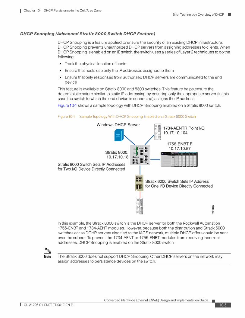
Chapter 10 DHCP Persistence in the Cell/Area Zone Brief Technology Overview of DHCP
DHCP Snooping (Advanced Stratix 8000 Switch DHCP Feature)
DHCP Snooping is a feature applied to ensure the security of an existing DHCP infrastructure. DHCP Snooping prevents unauthorized DHCP servers from assigning addresses to clients. When DHCP Snooping is enabled on an IE switch, the switch uses a series of Layer 2 techniques to do the following:
• Track the physical location of hosts
• Ensure that hosts use only the IP addresses assigned to them
• Ensure that only responses from authorized DHCP servers are communicated to the end device
This feature is available on Stratix 8000 and 8300 switches. This feature helps ensure the deterministic nature similar to static IP addressing by ensuring only the appropriate server (in this case the switch to which the end device is connected) assigns the IP address.
Figure10-1 shows a sample topology with DHCP Snooping enabled on a Stratix 8000 switch.
Figure10-1 Sample Topology With DHCP Snooping Enabled on a Stratix 8000 Switch
In this example, the Stratix 8000 switch is the DHCP server for both the Rockwell Automation 1756-ENBT and 1734-AENT modules. However, because both the distribution and Stratix 6000 switches act as DCHP servers also tied to the IACS network, multiple DHCP offers could be sent over the subnet. To prevent the 1734-AENT or 1756-ENBT modules from receiving incorrect addresses, DHCP Snooping is enabled on the Stratix 8000 switch.
Note The Stratix 6000 does not support DHCP Snooping. Other DHCP servers on the network may assign addresses to persistence devices on the switch.
2903
46
1734-AENTR Point I/O10.17.10.104
Stratix 6000 Switch Sets IP Addressfor One I/O Device Directly Connected
Stratix 8000 Switch Sets IP Addressesfor Two I/O Device Directly Connected
Windows DHCP Server
Stratix 8000:10.17.10.18
1756-ENBT F10.17.10.57
10-5Converged Plantwide Ethernet (CPwE) Design and Implementation Guide
OL-21226-01, ENET-TD001E-EN-P

Chapter 10 DHCP Persistence in the Cell/Area Zone DHCP Persistence Reference Architectures Testing
Table10-1 lists additional information on topics related to DHCP.
DHCP Persistence Reference Architectures TestingTo ensure proper address assignment via DHCP Persistence, the large-scale reference architecture topology shown in Figure10-2 was tested. The topology included eight Stratix 8000 switches connected in a ring to a Cisco Catalyst 4500 distribution switch. Each Stratix 8000 switch had DHCP-enabled IACS devices such as Rockwell Automation programmable controllers and I/O modules connected to it. In addition, to ensure that each IE switch acts as a DHCP server only to the IACS devices directly connected to it, the Stratix 6000 switch was added into the topology. A PowerFlex drive and Point I/O module were connected directly to the Stratix 6000 switch. The Windows DHCP Server was also added to act as an outside server to the system. If DHCP Snooping was performing as planned, the Windows server should not allocate any addresses to the end devices.
Note DHCP Persistence is not available on all switches. Contact the switch manufacturer for more information.
Table10-1 For More Information on DHCP
For More Information on: Visit:
IP Addressing and Subnetting for New Users http://www.cisco.com/en/US/tech/tk365/technologies_tech_note09186a00800a67f5.shtml
Internetworking Technology Handbook: IP http://www.cisco.com/en/US/docs/internetworking/technology/handbook/Internet-Protocols.html#wp4145
Configuring IP Addressing http://www.cisco.com/en/US/docs/ios/12_2/ip/configuration/guide/1cfipadr.html#wp1001046
Converged Plantwide Ethernet (CPwE) Design and Implementation Guide: IP Addressing
IP Addressing, page 4-38
10-6Converged Plantwide Ethernet (CPwE) Design and Implementation Guide
OL-21226-01, ENET-TD001E-EN-P

Chapter 10 DHCP Persistence in the Cell/Area Zone DHCP Persistence Reference Architectures Testing
Figure10-2 Typical Large-scale Topology
Test CriteriaThe tests were designed with the following criteria in mind:
• Ensure DHCP Persistence when multiple Stratix 8000 and Stratix 6000 switches act as DHCP servers
• Ensure DHCP Snooping functionality on Stratix 8000 Switches when a Stratix 6000 switch is enabled as a DHCP server
• Ensure DHCP Snooping functionality on Stratix 8000 Switches when an external Windows DHCP server is enabled
2903
47
1758-AENTR Point I/O10.17.10.222
1734-AENT Flex I/O10.17.10.100
1758-AENTR Point I/O10.17.10.103
PowerFlex 70EC Drive10.17.10.120
Catalyst 2960
Catalyst 4500
Windows DHCP Server10.18.2.40
Stratix 8000:10.17.10.18
Stratix 8000:10.17.10.17
Stratix 8000:10.17.10.16
Stx 8000:10.17.10.15
Stratix 8000:10.17.10.11
Stratix 8000:10.17.10.12
Stratix 8000:10.17.10.13
Stratix 6000:10.17.10.27
Stratix 8000:10.17.10.14
1756-ENBT (C)10.17.10.52
1756-ENBT (D)10.17.10.54
1756-ENBT (G)10.17.10.58
1756-ENBT (H)10.17.10.60 1756-ENBT F
10.17.10.57
1756-ENBT (E)10.17.10.56
1756-ENBT (A)10.17.10.50
1756-ENBT (B)10.17.10.51
1758-AENTR Point I/O10.17.10.104
10-7Converged Plantwide Ethernet (CPwE) Design and Implementation Guide
OL-21226-01, ENET-TD001E-EN-P
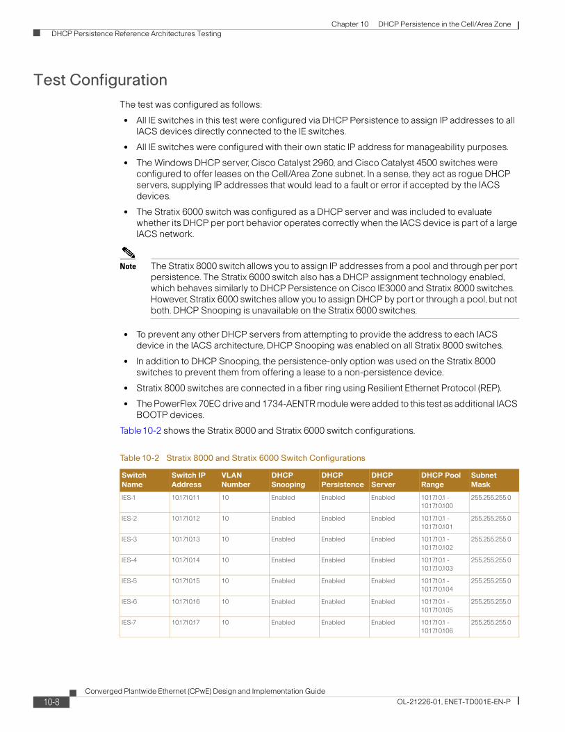
Chapter 10 DHCP Persistence in the Cell/Area Zone DHCP Persistence Reference Architectures Testing
Test ConfigurationThe test was configured as follows:
• All IE switches in this test were configured via DHCP Persistence to assign IP addresses to all IACS devices directly connected to the IE switches.
• All IE switches were configured with their own static IP address for manageability purposes.
• The Windows DHCP server, Cisco Catalyst 2960, and Cisco Catalyst 4500 switches were configured to offer leases on the Cell/Area Zone subnet. In a sense, they act as rogue DHCP servers, supplying IP addresses that would lead to a fault or error if accepted by the IACS devices.
• The Stratix 6000 switch was configured as a DHCP server and was included to evaluate whether its DHCP per port behavior operates correctly when the IACS device is part of a large IACS network.
Note The Stratix 8000 switch allows you to assign IP addresses from a pool and through per port persistence. The Stratix 6000 switch also has a DHCP assignment technology enabled, which behaves similarly to DHCP Persistence on Cisco IE3000 and Stratix 8000 switches. However, Stratix 6000 switches allow you to assign DHCP by port or through a pool, but not both. DHCP Snooping is unavailable on the Stratix 6000 switches.
• To prevent any other DHCP servers from attempting to provide the address to each IACS device in the IACS architecture, DHCP Snooping was enabled on all Stratix 8000 switches.
• In addition to DHCP Snooping, the persistence-only option was used on the Stratix 8000 switches to prevent them from offering a lease to a non-persistence device.
• Stratix 8000 switches are connected in a fiber ring using Resilient Ethernet Protocol (REP).
• The PowerFlex 70EC drive and 1734-AENTR module were added to this test as additional IACS BOOTP devices.
Table10-2 shows the Stratix 8000 and Stratix 6000 switch configurations.
Table10-2 Stratix 8000 and Stratix 6000 Switch Configurations
Switch Name
Switch IP Address
VLAN Number
DHCP Snooping
DHCP Persistence
DHCP Server
DHCP Pool Range
Subnet Mask
IES-1 10.17.10.11 10 Enabled Enabled Enabled 10.17.10.1 - 10.17.10.100
255.255.255.0
IES-2 10.17.10.12 10 Enabled Enabled Enabled 10.17.10.1 - 10.17.10.101
255.255.255.0
IES-3 10.17.10.13 10 Enabled Enabled Enabled 10.17.10.1 - 10.17.10.102
255.255.255.0
IES-4 10.17.10.14 10 Enabled Enabled Enabled 10.17.10.1 - 10.17.10.103
255.255.255.0
IES-5 10.17.10.15 10 Enabled Enabled Enabled 10.17.10.1 - 10.17.10.104
255.255.255.0
IES-6 10.17.10.16 10 Enabled Enabled Enabled 10.17.10.1 - 10.17.10.105
255.255.255.0
IES-7 10.17.10.17 10 Enabled Enabled Enabled 10.17.10.1 - 10.17.10.106
255.255.255.0
10-8Converged Plantwide Ethernet (CPwE) Design and Implementation Guide
OL-21226-01, ENET-TD001E-EN-P

Chapter 10 DHCP Persistence in the Cell/Area Zone DHCP Persistence Reference Architectures Testing
Testing ProcedureAs part of automated DHCP Persistence testing, the following procedure was observed.
Procedure
Step 1 Ensure all nodes and switches have correct IP addresses.
Step 2 Send CIP reset message to all nodes on network (simulates a node power cycle; forcing the DHCP IP assignment process to be repeated).
Step 3 Increment the test counter.
Step 4 Ensure all nodes have been reset.
Step 5 Ensure all nodes have received correct IP addresses.
Step 6 Repeat the procedure, beginning at step 1.
Although the automated test suite used a programmatic CIP reset message for power cycling, a manual power cycle test was added to verify the impact of an actual power cycle. Similar results were achieved through 25 manual power cycles. During the manual test the following procedure was observed:
Procedure
Step 1 Ensure all nodes and switches have correct IP addresses.
Step 2 Remove power from all devices on the network.
Step 3 Add power to all devices on network.
Step 4 Increment the test counter.
Step 5 Ensure all devices have been reset.
Step 6 Ensure all devices have received correct IP addresses.
Step 7 Repeat the procedure, beginning at step 1.
IES-8 10.17.10.18 10 Enabled Enabled Enabled 10.17.10.1 - 10.17.10.107
255.255.255.0
Stratix 6000 10.17.10.27 10 Enabled Enabled On - Assigned by Port
10.168.1.70 - 10.168.1.101
255.255.255.0
Table10-2 Stratix 8000 and Stratix 6000 Switch Configurations (continued)
Switch Name
Switch IP Address
VLAN Number
DHCP Snooping
DHCP Persistence
DHCP Server
DHCP Pool Range
Subnet Mask
10-9Converged Plantwide Ethernet (CPwE) Design and Implementation Guide
OL-21226-01, ENET-TD001E-EN-P

Chapter 10 DHCP Persistence in the Cell/Area Zone DHCP Persistence Design Recommendations for IACS Devices
Test ResultsThe automated test suite successfully completed over 1500 iterations of the test. The Stratix 8000 switches used DHCP Snooping and DHCP Persistence to ensure that the correct IP addresses were given to all IACS devices directly connected to the IE switch. The Stratix 6000 switch used DHCP Persistence to ensure that the correct IP addresses were given to all IACS devices directly connected to the IE switch.
The testing confirmed that all IACS devices successfully received the expected IP addresses as planned.
DHCP Persistence Design Recommendations for IACS Devices
Keep the following in mind when planning a system that uses DHCP Persistence for IP addressing.
• Plan IP addressing and VLAN scheme.
For recommendations on IP addressing, see Chapter 4, “CPwE Solution Design—Manufacturing and Demilitarized Zones,” and Table 4-7.
• Set up the IE switch with DHCP Persistence with planned IP addresses. Do not mix dynamic assignments and reservations on the same VLAN.
For additional information on setting up the Stratix 8000 switch, see Rockwell Automation publication, “Stratix 8000 and Stratix 8300 Ethernet Managed Switch User Manual”, available at the following URL:
http://literature.rockwellautomation.com/idc/groups/literature/documents/um/1783-um003_-en-p.pdf
• Enable DHCP Persistence on the Stratix 8000 switch if the switch by using the Device Manager web interface:
For additional information on setting DHCP Persistence, creating the DHCP pool of IP addresses, and enabling DHCP Persistence per port on the Stratix 8000 switch, see Rockwell Automation publication, “Stratix 8000 and Stratix 8300 Ethernet Managed Switch User Manual”, available at the following URL:
http://literature.rockwellautomation.com/idc/groups/literature/documents/um/1783-um003_-en-p.pdf
• Enable DHCP Snooping on the Stratix 8000 switch to prevent rogue DHCP servers from assigning IP addresses to the end nodes.
For additional information on enabling DHCP Snooping on the Stratix 8000 switch, see Rockwell Automation publication, “Stratix 8000 and Stratix 8300 Ethernet Managed Switch User Manual”, available at the following URL:
http://literature.rockwellautomation.com/idc/groups/literature/documents/um/1783-um003_-en-p.pdf
• Enable DHCP Per Port on the Stratix 6000 switch
For additional information on setting DHCP Per Port on Stratix 6000 switch, see Rockwell Automation publication, “Stratix 6000 Ethernet Managed Switch User Manual”, available at the following URL:
10-10Converged Plantwide Ethernet (CPwE) Design and Implementation Guide
OL-21226-01, ENET-TD001E-EN-P

Chapter 10 DHCP Persistence in the Cell/Area Zone DHCP Persistence Design Recommendations for IACS Devices
http://literature.rockwellautomation.com/idc/groups/literature/documents/um/1783-um001_-en-p.pdf
DHCP Persistence Configuration TechniquesKeep these techniques in mind as you configure your IACS application to use DHCP Persistence:
• Ensure all IACS devices on the IACS network are configured to use DHCP or BOOTP.
• If any IACS device cannot be configured for DHCP or BOOTP, configure the IACS devices with a static IP address.
• Ensure all IACS devices are configured out-of-the-box for DHCP or BOOTP when powered up.
• Wire the IACS network and confirm proper IP allocation to the IACS devices by using RSLinx software.
• If there are two or more identical IACS devices in your IACS network, check the MAC ID to ensure each IACS device has its IP address allocated properly.
• Check the web interface of the IACS device to ensure that the MAC address of the IACS device attached to port is as planned.
DHCP Persistence Topology ConsiderationsDHCP Persistence functionality is not affected by the IACS network topology in which it is applied. However, only one IACS device can be connected to an IE switch port. Regardless of the topology, the switch allocates IP addresses to all DHCP-enabled devices connected directly to it. However, there are several considerations to be pointed out for each topology.
Note Because DHCP Persistence allows only a single device to be connected per port, do not use DHCP Persistence with two-port Ethernet modules, such as the 1756-EN2TR, 1756-EN3TR, or 1734-AENTR modules. If you attempt to use DHCP Persistence with these modules, only one of the modules is assigned an IP address. The remaining modules are not assigned IP addresses.
10-11Converged Plantwide Ethernet (CPwE) Design and Implementation Guide
OL-21226-01, ENET-TD001E-EN-P

Chapter 10 DHCP Persistence in the Cell/Area Zone DHCP Persistence Design Recommendations for IACS Devices
Linear Topology
In a linear topology, each IE switch should be configured with DHCP Persistence enabled to allow dynamic address allocation to all IACS devices attached to them. In Figure10-3, every IACS device on the access link layer would have an IP address assigned by the IE switch to which it is attached. The IE switch would assign the address IP address by port. All IE switches are configured with their own static IP address for manageability purposes.
Figure10-3 Linear Topology
10-12Converged Plantwide Ethernet (CPwE) Design and Implementation Guide
OL-21226-01, ENET-TD001E-EN-P

Chapter 10 DHCP Persistence in the Cell/Area Zone DHCP Persistence Design Recommendations for IACS Devices
Star Topology
In a star topology, IACS devices on the access link layer receive their IP addresses from the IE switch to which they are attached. In this configuration (see Figure10-4), the IE switch assigns addresses per port for the IACS devices connected to it.. All IE switches are configured with their own static IP address for manageability purposes. DHCP Snooping is enabled on all IE switches. This prevents the IACS device from receiving IP addresses from the wrong DHCP servers.
Figure10-4 Star Topology
10-13Converged Plantwide Ethernet (CPwE) Design and Implementation Guide
OL-21226-01, ENET-TD001E-EN-P

Chapter 10 DHCP Persistence in the Cell/Area Zone DHCP Persistence Design Recommendations for IACS Devices
Ring Topology
In a ring topology (see Figure10-5), much like the other topologies, it is necessary to set up DHCP Persistence on each IE switch with connected IACS devices. An IE switch on one side of the ring cannot serve IP addresses to IACS devices connected to another IE switch elsewhere on the ring with DHCP Snooping configured. All IE switches are configured with their own static IP address for manageability purposes.
Figure10-5 Ring Topology
10-14Converged Plantwide Ethernet (CPwE) Design and Implementation Guide
OL-21226-01, ENET-TD001E-EN-P

Chapter 10 DHCP Persistence in the Cell/Area Zone DHCP Persistence Design Recommendations for IACS Devices
Redundant Star Topology
A redundant star topology (see Figure10-6) requires configuration of DHCP Persistence on each IE switch. The resiliency provided between IE switches does not affect configuration of DHCP Persistence. All IE switches are configured with their own static IP address for manageability purposes.
Figure10-6 Redundant Star Topology
10-15Converged Plantwide Ethernet (CPwE) Design and Implementation Guide
OL-21226-01, ENET-TD001E-EN-P

Chapter 10 DHCP Persistence in the Cell/Area Zone DHCP Persistence Design Recommendations for IACS Devices
10-16Converged Plantwide Ethernet (CPwE) Design and Implementation Guide
OL-21226-01, ENET-TD001E-EN-P
Converged Plantwide Ethernet (CPwOL-21226-01, ENET-TD001E-EN-P
A P P E N D I X A
Key Terms and DefinitionsThis appendix lists and defines the key terms used in this document.
AAA
Authentication, authorization, and accounting. Pronounced “triple a.”
For more on Authentication Protocols, see: http://www.cisco.com/en/US/tech/tk59/tsd_technology_support_protocol_home.html
ACL
Access Control Lists are used for purposes filtering IP traffic generally for security reasons.
For more on ACLs, see IP Addressing Services – Access Lists: http://www.cisco.com/en/US/tech/tk648/tk361/tk821/tsd_technology_support_sub-protocol_home.html
Active Directory
Microsoft’s application that delivers LDAP and other AAA services.
Cell/Area Zone
A logical section or subset (physical, geographical or function) of the production facility. It typically contains Level 0-2 devices (see Automation and Control Reference Model).
CIP Common Industrial Protocol
The Common Industrial Protocol (CIP™) encompasses a comprehensive suite of messages and services for the collection of manufacturing automation applications—control, safety, synchronization, motion, configuration and information. CIP is owned and maintained by the Open Device Vendor Association. The ODVA is an international association comprising members from the world's leading automation companies.
Control Plane
Control plane refers to network protocol traffic (e.g. routing, resiliency) that usually passes between network infrastructure devices to maintain the network’s functions. Examples of control plane traffic include Spanning Tree and EIGRP.
CSMA/CD
Carrier sense multiple access collision detect. Media-access mechanism wherein devices ready to transmit data first check the channel for a carrier. If no carrier is sensed for a specific period of time, a device can transmit. If two devices transmit at once, a collision occurs and is detected by all colliding devices. This collision subsequently delays retransmissions from those devices for some random length of time. Ethernet and IEEE 802.3 use CSMA/CD access.
A-1E) Design and Implementation Guide

Appendix A Key Terms and Definitions
Data Plane
Data plane refers to the application data the network switches and routes being sent to and from end-devices. CIP is considered data plane traffic.
DHCP
Dynamic Host Configuration Protocol. Provides a mechanism for allocating IP addresses dynamically so that addresses can be reused when hosts no longer need them.
Determinism
A property of an overall automation and control system that behaves determined only by initial state and input. Many factors impact the deterministic nature of a system, including network performance. For the purposes of this document, we will consider the network low latency, minimal jitter and minimal packet loss as the key network criteria that impact the deterministic nature of the overall automation and control system.
DMZ, Demilitarized Zone
Refers to a buffer or network segment between two network zones. A DMZ is commonly found between a corporate network and the internet where data and services can be shared/accessed from users in either the internet or corporate networks. A DMZ is typically established with network firewalls to manage and secure the traffic from either zone.
For an example of a network DMZ, see Scenario: DMZ Configuration: http://www.cisco.com/en/US/docs/security/pix/pix72/quick/guide/dmz_p.html
DNS
Domain Name System. System used on the Internet for translating names of network nodes into IP addresses.
Ethernet
Baseband LAN specification invented by Xerox Corporation and developed jointly by Xerox, Intel, and Digital Equipment Corporation. Ethernet networks use CSMA/CD and run over a variety of cable types and speeds. Ethernet is a family of frame-based networking technologies or standards (IEEE 802.3) for local area networks. It defines standards for common addressing format and the physical and data link (or Media Access Control) layers of the OSI Model.
See the IEEE 802.3 working group's site (http://www.ieee802.org/3/) for more details on the set of standards.
For more on Ethernet, see Ethernet – Introduction: http://www.cisco.com/en/US/tech/tk389/tk214/tsd_technology_support_protocol_home.html & Internetworking Technology Handbook-Ethernet: http://www.cisco.com/en/US/docs/internetworking/technology/handbook/Ethernet.html
IKE
Internet Key Exchange. IKE establishes a shared security policy and authenticates keys for services (such as IPSec) that require keys. Before any IPSec traffic can be passed, each router/firewall/host must verify the identity of its peer. This can be done by manually entering pre-shared keys into both hosts or by a CA service.
Industrial Automation and Control Systems (IACS)
Refers to the set of devices and applications used to automate and control the relevant manufacturing process. Rather than use various terms with a similar meaning (e.g., production systems, factory floor systems, we standardized on this term for use in this paper). That is not to suggest any specific focus or limitations. We intend that the ideas and concepts outline herein are applicable in various types of manufacturing including but not limited to batch, continuous, discrete, hybrid and process. Other documents and industry references may refer to Industrial Control Systems (ICS). For the purpose of this document, those terms are interchangeable. This document simply choose to use IACS, as reflected in the ISA 99 standards.
IP
A-2Converged Plantwide Ethernet (CPwE) Design and Implementation Guide
OL-21226-01, ENET-TD001E-EN-P

Appendix A Key Terms and Definitions
Internet Protocol. Network layer protocol in the TCP/IP stack offering a connectionless internetwork service. IP provides features for addressing, type-of-service specification, fragmentation and reassembly, and security. Defined in RFC 791.
For more on IP, TCP and UDP, see Internetworking Technology Handbook-Internet Protocols: http://www.cisco.com/en/US/docs/internetworking/technology/handbook/Internet-Protocols.html
IP Protocol Suite
Is a set of networking standards on which the internet and most enterprise networking is based. It includes the Layer 3 Internet Protocol (IP), the Layer-4 Transmission Control Protocol (TCP) and User Datagram Protocol (UDP).
IPS
Intrusion Prevention Systems is a network security device that monitors network activity for malicious or unwanted behavior.
See more on Intrusion Prevention Systems at widpedia: http://en.wikipedia.org/wiki/Intrusion-prevention_system or Cisco IPS: http://www.cisco.com/en/US/products/sw/secursw/ps2113/index.html
IPSec
IP Security. A framework of open standards that provides data confidentiality, data integrity, and data authentication between participating peers. IPSec provides these security services at the IP layer. IPSec uses IKE (See above) to handle the negotiation of protocols and algorithms based on local policy and to generate the encryption and authentication keys to be used by IPSec. IPSec can protect one or more data flows between a pair of hosts, between a pair of security gateways, or between a security gateway and a host.
For a more in-depth understanding of IPsec, see the following URL: http://www.cisco.com/en/US/tech/tk583/tk372/technologies_tech_note09186a0080094203.shtml.
ISA-99
ISA-99 focuses on security for industrial automation and control systems, For more, see http://www.isa.org/MSTemplate.cfm?MicrositeID=988&CommitteeID=6821
ISA-95
The standard for the integration of enterprise and control systems, see http://www.isa.org/Template.cfm?Section=Find_Standards&Template=/Customsource/ISA/Standards/TaggedStandardsCommittee.cfm&id=2360
Jitter
Refers to the variation in Latency (see definition below). Jitter is important as often larger variations in the delay due to communications can negatively impact the 'deterministic' nature of the relevant system.
Latency
Refers to the delay in communications due to processing and transmission media (Switches, Routers and cables) between any two end-devices. Latency could also refer to the processing time in an application to process a message.
Layer
Generally refers to layers of the OSI Model which logically describe the functions that make up networked communications (see Chapter 1, Figure 8).
Level
Refers to levels of the Automation and Control Reference Model (see Chapter2) that describe functions and domains of control within manufacturing organizations. This Model is based upon the Purdue Control Hierarchy model and is used in a variety of Industrial standards (e.g. ISA 95 and 99).
LDAP
A-3Converged Plantwide Ethernet (CPwE) Design and Implementation Guide
OL-21226-01, ENET-TD001E-EN-P

Appendix A Key Terms and Definitions
Lightweight Directory Access Protocol. Protocol that provides access for management and browser applications that provide read/write interactive access to an X.500 compliant directory service. X.500 specifies a standard for distributed maintenance of files and directories.
Manufacturing Zone
The Manufacturing zone is a network zone in the Automation and Control Reference Model (see Chapter 2) The zone contains the complete set of applications, systems, infrastructure and devices that are critical to the continued operations of the plant.
In other documentation (for example ISA 99), this zone may also be referred to as the Control zone. The terms are interchangeable in this regard.
NAC
Lightweight Directory Access Protocol. Protocol that provides access for management and browser applications that provide read/write interactive access to an X.500 compliant directory service. X.500 specifies a standard for distributed maintenance of files and directories.
NAC
Network Access Control is a security approach that allows only compliant and trusted endpoint devices, such as PCs, servers, and PDAs, onto the network, restricting the access of noncompliant devices, and thereby limiting the potential damage from emerging security threats and risks.
For more on Network Admission Control, see: http://www.cisco.com/en/US/netsol/ns466/networking_solutions_package.html
NAT Network Address Translation
Network Address Translation is a mechanism for reducing the need for globally unique IP addresses. NAT allows an organization with addresses that are not globally unique to connect to the Internet by translating those addresses into globally routable address space.
Network Convergence
The period of time the network requires to restore normal network traffic handling after an outage or event. For our testing and test results, convergence time is measured using the following formula:
Convergence in milliseconds = [(Tx - Rx) / packet rate] * 1000 ms/s
Where:
Tx = Packets transmitted
Rx = Packets received
Packet rate tested = 10,000 packets per second
ODVA Open Device Vendors Association
ODVA is an international association comprising members from the world's leading automation companies. Collectively, ODVA and its members support network technologies based on the Common Industrial Protocol (CIP™). These currently include DeviceNet™, EtherNet/IP™, CompoNet™, and ControlNet™, along with the major extensions to CIP — CIP Safety™ and CIP Motion™. ODVA manages the development of these open technologies, and assists manufacturers and users of CIP Networks through its activities in standards development, certification, vendor education and industry awareness. Both Rockwell Automation and Cisco are members of the ODVA.
OSI Model
A-4Converged Plantwide Ethernet (CPwE) Design and Implementation Guide
OL-21226-01, ENET-TD001E-EN-P

Appendix A Key Terms and Definitions
The Open Systems Interconnection model is a Network architectural model consisting of seven layers, each of which specifies particular network functions, such as addressing, flow control, error control, encapsulation, and reliable message transfer. The lowest layer (the physical layer) is closest to the media technology. The lower two layers are implemented in hardware and software whereas the upper five layers are implemented only in software. The highest layer (the application layer) is closest to the user. The OSI reference model is used universally as a method for teaching and understanding network functionality
The term layer in this document generally refers to a layer or layers of the OSI Model.
See Chapter 1, Figure 8 for a diagram of the OSI Model.
Plant
Plant, Production Facility, Factory or Factory Floor—This document chose to use the term plant as a keyword to describe the area in which the manufacturing process and control takes place. This is not to exclude similar words such as factory, production facility, or any other term used to refer to the area in which the manufacturing process exists. In fact, they can be used interchangeably, but for the purpose of consistency, we chose to use Plant.
Port
A port can refer to two things in networking.
1. Physical Interface on an internetworking device (such as a router).
2. In IP terminology, an upper-layer process that receives information from lower layers. Port is an application-specific or process-specific software construct serving as a communications endpoint used by Transport Layer protocols of the Internet Protocol Suite such as Transmission Control Protocol (TCP) and User Datagram Protocol (UDP). Ports are numbered (a port number), and each numbered port is associated with a specific process. For example, SMTP is associated with port 25. A port number is also called a well-known address. For a list of official port numbers see The Internet Assigned Numbers Authority (IANA) at the following URL: http://www.iana.org/assignments/port-numbers.
For the purpose of this document, port refers to the second meaning.
RADIUS
Remote Authentication Dial In User Service (RADIUS) is a networking protocol that provides centralized access, authorization and accounting management for pe.ople or computers to connect and use a network service. When a person or device connects to a network often “RADIUS” authentication is required.
Remote Terminal Session
Remote Terminal Session of Remote Desktop refers to a set of protocols and software that enable one computer or user to remotely access and control another computer through graphical Terminal Emulation. Software that makes it appear to a remote host as a directly attached terminal, including Microsoft’s RDP, Remote Desktop Protocol and VNC Virtual Network Computing.
SSL
Secure Socket Layer. Encryption technology for the Web used to provide secure transactions, such as the transmission of credit card numbers for e-commerce.
Subnet or Subnetwork
In IP networks, a subnet is a network sharing a particular subnet address. Subnetworks are networks arbitrarily segmented by a network administrator in order to provide a multilevel, hierarchical routing structure while shielding the subnetwork from the addressing complexity of attached networks.
TCP
Transmission Control Protocol. Connection-oriented transport layer protocol that provides reliable full-duplex data transmission. TCP is part of the TCP/IP protocol stack.
For more on IP, TCP and UDP, see Internetworking Technology Handbook-Internet Protocols: http://www.cisco.com/en/US/docs/internetworking/technology/handbook/Internet-Protocols.html
A-5Converged Plantwide Ethernet (CPwE) Design and Implementation Guide
OL-21226-01, ENET-TD001E-EN-P

Appendix A Key Terms and Definitions
UDP
User Datagram Protocol. Connectionless transport layer protocol in the TCP/IP protocol stack. UDP is a simple protocol that exchanges datagrams without acknowledgments or guaranteed delivery, requiring that error processing and retransmission be handled by the application or other protocols. UDP is defined in RFC 768.
For more on IP, TCP and UDP, see http://www.cisco.com/en/US/docs/internetworking/technology/handbook/Internet-Protocols.htm
VLAN
virtual LAN. Group of devices on one or more LANs that are configured (using management software) so that they can communicate as if they were attached to the same wire, when in fact they are located on a number of different LAN segments. Because VLANs are based on logical instead of physical connections, they are extremely flexible.
For more on VLANs, see Internetworking Technology Handbook-Lan Switching http://www.cisco.com/en/US/docs/internetworking/technology/handbook/LAN-Switching.html
VPN
Virtual Private Network. Enables IP traffic to travel securely over a public TCP/IP network by encrypting all traffic from one network to another. A VPN uses “tunneling” to encrypt all information at the IP level.
For more on VPNs, see “How VPNs work”: http://www.cisco.com/en/US/tech/tk583/tk372/technologies_tech_note09186a0080094865.shtml or “IPSec VPN WAN Design Overview” http://www.cisco.com/en/US/docs/solutions/Enterprise/WAN_and_MAN/IPSec_Over.html#wp1006588
WINS
Windows Internet Naming Service. Microsoft’s NetBIOS name translation service, analogous to DNS.
A-6Converged Plantwide Ethernet (CPwE) Design and Implementation Guide
OL-21226-01, ENET-TD001E-EN-P

Converged Plantwide Ethernet (CPwOL-21226-01, ENET-TD001E-EN-P
A P P E N D I X B
Test Result AnalysisThis appendix provides some comparison and analysis of the test results in Appendix C, “Complete Test Data.” The analysis summarizes and compare test cases from a variety of test suites to draw conclusions. These conclusions and the overall test approach are described in Chapter 7, “Testing the CPwE Solution.” The key analysis includes the following:
• Impact of the number of switches on network convergence in a ring topology (8 versus 16 switches)
• Impact of Spanning Tree Protocol (STP) on network convergence in a ring topology.
• Impact of topology/resiliency protocol on network convergence (ring vs. redundant star topologies) with both copper and fiber media situations
• Impact of uplink media type used (fiber versus copper) on network convergence
• Impact of number of MAC addresses on network convergence
• Analysis of network restoration events
• Analysis of application latency (screw-to-screw) tests
The summary of the test case includes the following:
• Minimum, maximum, and average measured network convergence from the all test iterations and measurement points as a set
• The maximum measured network convergence in east test iteration averaged for all test iterations (MaxAvg)
All of this information is valuable. As the purpose of this section is to compare the test results and draw conclusions, it is useful to compare some information between the test cases. Cisco and Rockwell Automation chose to use the MaxAvg as the best representation of network convergence between the test suites on which to draw conclusions. The minimum and maximum numbers, although informative, were not useful as a basis to analyze and draw conclusions. The average of the set of test iterations was also not used as this number varies significantly when some measurement points are more impacted than others depending on the test suite. The MaxAvg, therefore, was determined to be a better representation of network convergence when analyzing and drawing conclusions.
B-1E) Design and Implementation Guide
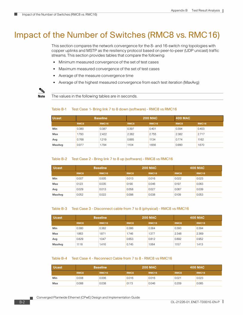
Appendix B Test Result Analysis Impact of the Number of Switches (RMC8 vs. RMC16)
Impact of the Number of Switches (RMC8 vs. RMC16)This section compares the network convergence for the 8- and 16-switch ring topologies with copper uplinks and MSTP as the resiliency protocol based on peer-to-peer (UDP unicast) traffic streams. This section provides tables that compare the following:
• Minimum measured convergence of the set of test cases
• Maximum measured convergence of the set of test cases
• Average of the measure convergence time
• Average of the highest measured convergence from each test iteration (MaxAvg)
Note The values in the following tables are in seconds.
Table B-1 Test Case 1- Bring link 7 to 8 down (software) - RMC8 vs RMC16
Ucast Baseline 200 MAC 400 MAC
RMC8 RMC16 RMC8 RMC16 RMC8 RMC16
Min 0.380 0.387 0.397 0.401 0.394 0.403
Max 1.793 2.422 2.362 2.755 2.382 2.717
Avg 0.768 1.219 0.885 1.134 0.774 1.162
MaxAvg 0.977 1.794 1.104 1.656 0.990 1.670
Table B-2 Test Case 2 - Bring link 7 to 8 up (software) - RMC8 vs RMC16
Ucast Baseline 200 MAC 400 MAC
RMC8 RMC16 RMC8 RMC16 RMC8 RMC16
Min 0.007 0.005 0.013 0.016 0.022 0.023
Max 0.123 0.035 0.190 0.046 0.197 0.063
Avg 0.029 0.013 0.058 0.027 0.067 0.039
MaxAvg 0.052 0.022 0.098 0.038 0.109 0.053
Table B-3 Test Case 3 - Disconnect cable from 7 to 8 (physical) - RMC8 vs RMC16
Ucast Baseline 200 MAC 400 MAC
RMC8 RMC16 RMC8 RMC16 RMC8 RMC16
Min 0.380 0.382 0.386 0.384 0.393 0.394
Max 1.863 1.871 1.746 1.377 2.348 2.369
Avg 0.829 1.047 0.653 0.812 0.892 0.952
MaxAvg 1.118 1.416 0.745 1.064 1.157 1.413
Table B-4 Test Case 4 - Reconnect Cable from 7 to 8 - RMC8 vs RMC16
Ucast Baseline 200 MAC 400 MAC
RMC8 RMC16 RMC8 RMC16 RMC8 RMC16
Min 0.008 0.006 0.016 0.016 0.021 0.023
Max 0.088 0.038 0.173 0.046 0.209 0.065
B-2Converged Plantwide Ethernet (CPwE) Design and Implementation Guide
OL-21226-01, ENET-TD001E-EN-P

Appendix B Test Result Analysis Impact of the Number of Switches (RMC8 vs. RMC16)
Avg 0.027 0.016 0.048 0.024 0.066 0.041
MaxAvg 0.050 0.029 0.085 0.035 0.110 0.057
Table B-5 Test Case 5 - Root bridge down (physical) - RMC8 vs RMC16
Ucast Baseline 200 MAC 400 MAC
RMC8 RMC16 RMC8 RMC16 RMC8 RMC16
Min 0.000 0.000 0.011 0.000 0.000 0.000
Max 1.852 1.637 1.765 1.650 2.565 1.296
Avg 0.438 0.547 0.501 0.460 0.570 0.415
MaxAvg 0.759 0.978 0.752 0.871 0.959 0.655
Table B-6 Test Case 6 - Root bridge up (physical) - RMC8 vs RMC16
Ucast Baseline 200 MAC 400 MAC
RMC8 RMC16 RMC8 RMC16 RMC8 RMC16
Min 0.017 0.008 0.034 0.022 0.045 0.048
Max 1.070 0.922 0.905 0.942 1.079 0.928
Avg 0.283 0.286 0.271 0.239 0.327 0.320
MaxAvg 0.489 0.499 0.388 0.444 0.463 0.465
Table B-7 Test Case 7 - Stack Master down - RMC8 vs RMC16
Ucast Baseline 200 MAC 400 MAC
RMC8 RMC16 RMC8 RMC16 RMC8 RMC16
Min 0.000 0.000 0.000 0.000 0.000 0.000
Max 1.737 1.762 2.748 1.864 2.401 1.815
Avg 0.435 0.501 0.498 0.538 0.493 0.545
MaxAvg 0.809 0.936 0.895 1.036 0.857 0.991
Table B-8 Test Case 8 - Stack Master up - RMC8 vs RMC16
Ucast Baseline 200 MAC 400 MAC
RMC8 RMC16 RMC8 RMC16 RMC8 RMC16
Min 0.000 0.000 0.000 0.000 0.000 0.000
Max 0.137 0.036 0.184 0.049 0.194 0.072
Avg 0.029 0.012 0.052 0.022 0.054 0.028
MaxAvg 0.055 0.020 0.079 0.031 0.086 0.041
Table B-4 Test Case 4 - Reconnect Cable from 7 to 8 - RMC8 vs RMC16 (continued)
Ucast Baseline 200 MAC 400 MAC
RMC8 RMC16 RMC8 RMC16 RMC8 RMC16
B-3Converged Plantwide Ethernet (CPwE) Design and Implementation Guide
OL-21226-01, ENET-TD001E-EN-P

Appendix B Test Result Analysis Impact of the Number of Switches (RMC8 vs. RMC16)
Figure B-1 shows the trend for physical cable disconnection (test case 3) between 8- and 16-switch ring topologies. In all cases, the number of switches slowed the network convergence of the STP. The same trend can be seen in the following failure test cases:
• Test Case 1—Bring Link Down
• Test Cast 3—Disconnect Cable
• Test Case 5—Root Bridge Down
• Test Case 7—Stack Master Down
Figure B-1 Impact of Number of Switches—Test Case 3 Disconnect Cable
The key findings were as follows:
• Convergence time on average is below one second, which is sufficient to avoid application timeouts for process and HMI applications (non-time critical). None of the test suites meet the requirements to avoid application timeouts in time-critical applications.
• The size of the ring impacts (slows down) the network convergence in link disruption test cases, although with the variability due to the copper media, this impact is difficult to quantify. The number of network infrastructure devices has less relevance in the other test cases.
• The impact of the number of MAC addresses was difficult to assess, most likely due to the variance introduced by the copper uplinks
B-4Converged Plantwide Ethernet (CPwE) Design and Implementation Guide
OL-21226-01, ENET-TD001E-EN-P

Appendix B Test Result Analysis Spanning Tree Protocol Comparison (RMC8 vs. RPC8)
Spanning Tree Protocol Comparison (RMC8 vs. RPC8)This section compares the MSTP and rapid PVST+ (RPVST+) STPs in 8-switch ring topologies with copper uplinks. This section provides tables that compare the following:
• Minimum measured convergence of the set of test cases
• Maximum measured convergence of the set of test cases
• Average of the measure convergence time
• Average of the highest measured convergence from each test iteration (MaxAvg)
Table B-9 Test Case 1 - Bring link 7 to 8 down (software) - RMC8 vs RPC8
Ucast Baseline
RMC8 RPC8
Min 0.380 0.395
Max 1.793 0.868
Avg 0.768 0.597
MaxAvg 0.977 0.610
Table B-10 Test Case 2 - Bring link 7 to 8 up (software) - RMC8 vs RPC8
Ucast Baseline
RMC8 RPC8
Min 0.007 0.007
Max 0.123 0.043
Avg 0.029 0.020
MaxAvg 0.052 0.028
Table B-11 Test Case 3 - Disconnect cable from 7 to 8 (physical) - RMC8 vs RPC8
Ucast Baseline
RMC8 RPC8
RMC8 RPC8
Min 0.380 0.390
Max 1.863 0.863
Avg 0.829 0.651
MaxAvg 1.118 0.675
Table B-12 Test Case 4 - Reconnect cable from 7 to 8 - RMC8 vs RPC8
Ucast Baseline
RMC8 RPC8
Min 0.008 0.009
Max 0.088 0.042
Avg 0.027 0.021
MaxAvg 0.050 0.030
B-5Converged Plantwide Ethernet (CPwE) Design and Implementation Guide
OL-21226-01, ENET-TD001E-EN-P

Appendix B Test Result Analysis Spanning Tree Protocol Comparison (RMC8 vs. RPC8)
Table B-13 Test Case 5 - Root bridge down (physical) - RMC8 vs RPC8
Ucast Baseline
RMC8 RPC8
Min 0.000 0.000
Max 1.852 0.894
Avg 0.438 0.294
MaxAvg 0.759 0.577
Table B-14 Test Case 6 - Root bridge up (physical) - RMC8 vs RPC8
Ucast Baseline
RMC8 RPC8
Min 0.017 0.013
Max 1.070 0.328
Avg 0.283 0.039
MaxAvg 0.489 0.055
Table B-15 Test Case 7 - Stack Master down - RMC8 vs RPC8
Ucast Baseline
RMC8 RPC8
Min 0.000 0.000
Max 1.737 0.875
Avg 0.435 0.311
MaxAvg 0.809 0.612
Table B-16 Test Case 8 - Adding switch back to the stack - RMC8 vs RPC8
Ucast Baseline
RMC8 RPC8
Min 0.000 0.000
Max 0.137 0.046
Avg 0.029 0.014
MaxAvg 0.055 0.024
B-6Converged Plantwide Ethernet (CPwE) Design and Implementation Guide
OL-21226-01, ENET-TD001E-EN-P

Appendix B Test Result Analysis Topology/Resiliency Protocol Analysis
Figure B-2 shows the trend for physical cable disconnection (test case 3) for each compared test suite.
Figure B-2 Disconnect cable
The key findings are as follows:
• In all key disruptions, including link disruption, stack-master and root-switch failure test cases, the peer-to-peer application timed out in all instances. Neither protocol converges the network in this configuration near the requirements to avoid timeouts in “time critical” applications
• RPVST+ network convergence is generally faster and less variable than MSTP.
In general, network convergence was fast enough in reestablishing links and restoring a switch in the switch-stack test cases to avoid peer-to-peer application timeouts. This suggests restoring connectivity may not require planned downtime for peer-to-peer applications. I/O (multicast-based) applications were not tested. See the “Restore Impact Analysis” section on page B-25 for more information.
Topology/Resiliency Protocol Analysis This section compares the test results from the various topology and resiliency protocol test suites. The analysis is split into two sections to compare the copper and fiber media-uplink test suites. This section provides tables that compare the following:
• Minimum measured convergence of the set of test cases
• Maximum measured convergence of the set of test cases
• Average of the measure convergence time
• Average of the highest measured convergence from each test iteration (MaxAvg)
Topology/Resiliency Protocol Analysis—Copper Uplinks (RMC8, SMC8, SEC8, SFC8)
This section compares the topologies and resiliency protocols (MSTP, EtherChannel, and Flex Links) in 8-switch topologies with copper uplinks based on peer-to-peer (UDP unicast) traffic streams.
B-7Converged Plantwide Ethernet (CPwE) Design and Implementation Guide
OL-21226-01, ENET-TD001E-EN-P

Appendix B Test Result Analysis Topology/Resiliency Protocol Analysis
Table B-17 Test Case 1- Bring link down (software) - RMC8, SMC8, SEC8 & SFC8
Ucast Baseline 200 MAC 400 MAC
RMC8 SEC8 SFC8 SMC8 RMC8 SEC8 SFC8 SMC8 RMC8 SEC8 SFC8 SMC8
Min 0.380 0.001 0.0047 0.010 0.397 0.001 0.005 0.022 0.394 0.0007 0.0066 0.034
Max 1.793 0.815 0.0726 0.058 2.362 0.425 0.179 0.146 2.382 0.4165 0.1396 0.172
Avg 0.768 0.317 0.0279 0.022 0.885 0.173 0.038 0.069 0.774 0.1311 0.0381 0.086
MaxAvg 0.977 0.632 0.0373 0.032 1.104 0.345 0.055 0.106 0.990 0.2612 0.0585 0.128
Table B-18 Test Case 2- Bring link up (software) - RMC8, SMC8, SEC8, SFC8
Ucast Baseline 200 MAC 400 MAC
RMC8 SEC8 SFC8 SMC8 RMC8 SEC8 SFC8 SMC8 RMC8 SEC8 SFC8 SMC8
Min 0.007 0.000 0 0.010 0.013 0.000 0 0.019 0.022 0.000 0 0.020
Max 0.123 0.032 0 0.037 0.190 0.016 0 0.104 0.197 0.017 0 0.158
Avg 0.029 0.015 0 0.020 0.058 0.009 0 0.046 0.067 0.010 0 0.068
MaxAvg 0.052 0.019 0 0.030 0.098 0.012 0 0.072 0.109 0.013 0 0.111
Table B-19 Test Case 3 - Disconnect cable (physical) - RMC8, SMC8, SEC8, SFC8
Ucast Baseline 200 MAC 400 MAC
RMC8 SEC8 SFC8 SMC8 RMC8 SEC8 SFC8 SMC8 RMC8 SEC8 SFC8 SMC8
Min 0.380 0.370 0.3498 0.387 0.386 0.180 0.3565 0.401 0.393 0.180 0.3488 0.415
Max 1.863 0.795 0.7696 0.811 1.746 0.787 0.7622 0.853 2.348 0.791 0.7671 0.856
Avg 0.829 0.581 0.5627 0.673 0.653 0.368 0.5648 0.628 0.892 0.389 0.563 0.696
MaxAvg 1.118 0.778 0.5671 0.677 0.745 0.508 0.5707 0.646 1.157 0.585 0.5709 0.720
Table B-20 Test Case 5 - Stack Master down (software) - RMC8, SMC8, SEC8, SFC8
Ucast Baseline 200 MAC 400 MAC
RMC8 SEC8 SFC8 SMC8 RMC8 SEC8 SFC8 SMC8 RMC8 SEC8 SFC8 SMC8
Min 0.000 0.000 0.3617 0.406 0.000 0.578 0.3695 0.425 0.000 0.598 0.4165 0.499
Max 1.737 1.227 0.8011 0.854 2.748 1.125 0.8065 0.938 2.401 1.004 1.243 0.954
Avg 0.435 0.602 0.6114 0.679 0.498 0.781 0.6341 0.683 0.493 0.681 0.8107 0.758
MaxAvg 0.809 0.847 0.6183 0.786 0.895 0.814 0.6469 0.796 0.857 0.687 0.8367 0.865
Table B-21 Test Case 6 - Restore stack switch (software) - RMC8, SMC8, SEC8, SFC8
Ucast Baseline 200 MAC 400 MAC
RMC8 SEC8 SFC8 SMC8 RMC8 SEC8 SFC8 SMC8 RMC8 SEC8 SFC8 SMC8
Min 0.000 0.000 0 0.023 0.000 0.006 0 0.052 0.000 0.007 0 0.072
Max 0.137 1.094 0.0008 0.840 0.184 0.396 0.0006 0.163 0.194 0.343 0.001 0.292
Avg 0.029 0.126 0.0002 0.104 0.052 0.062 8E-05 0.082 0.054 0.045 0.0001 0.127
MaxAvg 0.055 0.131 0.0002 0.132 0.079 0.069 8E-05 0.117 0.086 0.062 0.0001 0.175
B-8Converged Plantwide Ethernet (CPwE) Design and Implementation Guide
OL-21226-01, ENET-TD001E-EN-P
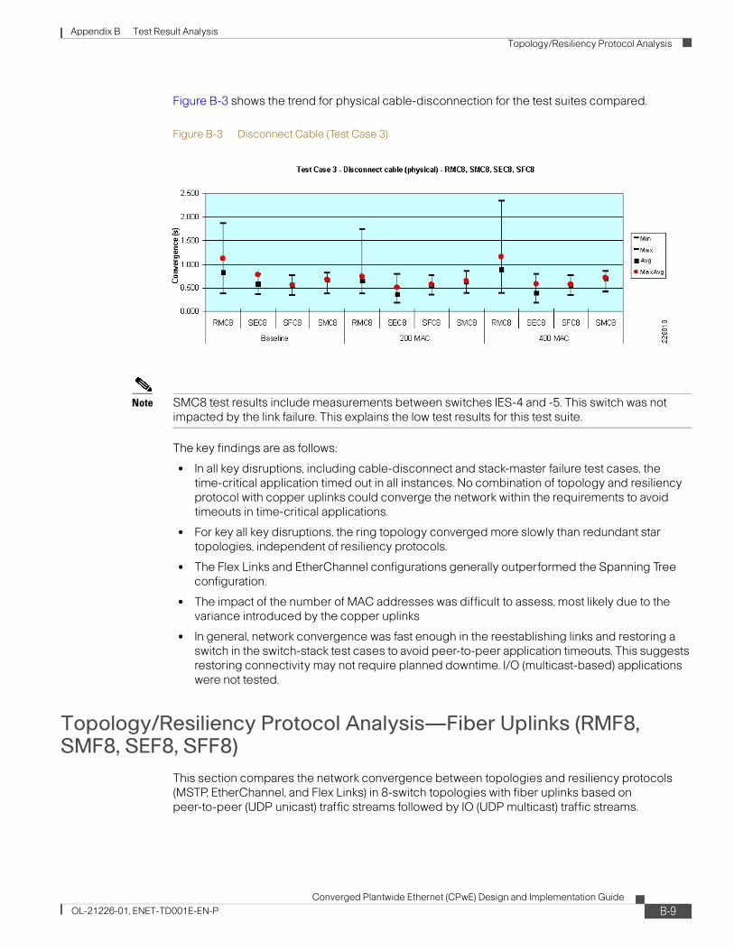
Appendix B Test Result Analysis Topology/Resiliency Protocol Analysis
Figure B-3 shows the trend for physical cable-disconnection for the test suites compared.
Figure B-3 Disconnect Cable (Test Case 3)
Note SMC8 test results include measurements between switches IES-4 and -5. This switch was not impacted by the link failure. This explains the low test results for this test suite.
The key findings are as follows:
• In all key disruptions, including cable-disconnect and stack-master failure test cases, the time-critical application timed out in all instances. No combination of topology and resiliency protocol with copper uplinks could converge the network within the requirements to avoid timeouts in time-critical applications.
• For key all key disruptions, the ring topology converged more slowly than redundant star topologies, independent of resiliency protocols.
• The Flex Links and EtherChannel configurations generally outperformed the Spanning Tree configuration.
• The impact of the number of MAC addresses was difficult to assess, most likely due to the variance introduced by the copper uplinks
• In general, network convergence was fast enough in the reestablishing links and restoring a switch in the switch-stack test cases to avoid peer-to-peer application timeouts. This suggests restoring connectivity may not require planned downtime. I/O (multicast-based) applications were not tested.
Topology/Resiliency Protocol Analysis—Fiber Uplinks (RMF8, SMF8, SEF8, SFF8)
This section compares the network convergence between topologies and resiliency protocols (MSTP, EtherChannel, and Flex Links) in 8-switch topologies with fiber uplinks based on peer-to-peer (UDP unicast) traffic streams followed by IO (UDP multicast) traffic streams.
B-9Converged Plantwide Ethernet (CPwE) Design and Implementation Guide
OL-21226-01, ENET-TD001E-EN-P

Appendix B Test Result Analysis Topology/Resiliency Protocol Analysis
Table B-22 Test Case 1 - Bring link down (software) - RMF8, SMF8, SEF8 & SFF8
Ucast Baseline 200 MAC 400 MAC
RMF8 SEF8 SFF8 SMF8 RMF8 SEF8 SFF8 SMF8 RMF8 SEF8 SFF8 SMF8
Min 0.051 0.000 0.005 0.011 0.051 0.000 0.012 0.031 0.063 0.000 0.005 0.046
Max 1.497 0.097 0.068 0.064 1.939 0.051 0.057 0.104 1.622 0.049 0.065 0.174
Avg 0.269 0.040 0.030 0.028 0.286 0.020 0.030 0.055 0.196 0.019 0.030 0.078
MaxAvg 0.467 0.075 0.040 0.043 0.464 0.039 0.037 0.077 0.318 0.038 0.043 0.103
Table B-23 Test Case 2 - Bring link up (software) - RMF8, SMF8, SEF8 & SFF8
Ucast Baseline 200 MAC 400 MAC
RMF8 SEF8 SFF8 SMF8 RMF8 SEF8 SFF8 SMF8 RMF8 SEF8 SFF8 SMF8
Min 0.007 0.000 0.000 0.010 0.007 0.000 0.000 0.019 0.021 0.000 0.000 0.030
Max 0.039 0.025 0.000 0.040 0.053 0.012 0.000 0.082 0.083 0.015 0.000 0.136
Avg 0.016 0.010 0.000 0.020 0.023 0.005 0.000 0.041 0.042 0.006 0.000 0.075
MaxAvg 0.028 0.012 0.000 0.029 0.043 0.006 0.000 0.062 0.061 0.007 0.000 0.119
Table B-24 Test Case 3 - Disconnect cable (physical) - RMF8, SMF8, SEF8 & SFF8
Ucast Baseline 200 MAC 400 MAC
RMF8 SEF8 SFF8 SMF8 RMF8 SEF8 SFF8 SMF8 RMF8 SEF8 SFF8 SMF8
Min 0.007 0.000 0.023 0.024 0.007 0.000 0.005 0.072 0.048 0.000 0.027 0.080
Max 1.987 0.132 0.075 0.157 1.417 0.063 0.058 0.144 1.173 0.062 0.097 0.175
Avg 0.309 0.051 0.052 0.078 0.234 0.026 0.039 0.098 0.322 0.026 0.049 0.118
MaxAvg 0.575 0.080 0.061 0.091 0.545 0.044 0.048 0.111 0.575 0.044 0.057 0.136
Table B-25 Test Case 4 - Reconnect cable (physical) - RMF8, SMF8, SEF8 & SFF8
Ucast Baseline 200 MAC 400 MAC
RMF8 SEF8 SFF8 SMF8 RMF8 SEF8 SFF8 SMF8 RMF8 SEF8 SFF8 SMF8
Min 0.007 0.000 0.000 0.010 0.007 0.000 0.000 0.020 0.022 0.000 0.000 0.030
Max 0.040 0.023 0.000 0.045 0.049 0.013 0.000 0.088 0.073 0.014 0.000 0.149
Avg 0.017 0.009 0.000 0.019 0.023 0.005 0.000 0.043 0.039 0.006 0.000 0.080
MaxAvg 0.030 0.011 0.000 0.028 0.043 0.006 0.000 0.064 0.057 0.007 0.000 0.129
Table B-26 Test Case 5 - Stack Master down (software) - SMF8, SEF8 & SFF8
Ucast Baseline 200 MAC 400 MAC
SEF8 SFF8 SMF8 SEF8 SFF8 SMF8 SEF8 SFF8 SMF8
Min 0.000 0.027 0.070 0.569 0.025 0.121 0.588 0.050 0.173
Max 1.232 0.086 0.127 0.668 0.073 0.202 0.667 0.103 0.269
Avg 0.545 0.053 0.096 0.612 0.054 0.158 0.617 0.075 0.215
MaxAvg 0.846 0.059 0.109 0.624 0.063 0.180 0.624 0.083 0.236
B-10Converged Plantwide Ethernet (CPwE) Design and Implementation Guide
OL-21226-01, ENET-TD001E-EN-P

Appendix B Test Result Analysis Topology/Resiliency Protocol Analysis
Table B-27 Test Case SMF8, SEF8, SFF8-6 - Stack Maser up (software)
Ucast Baseline 200 MAC 400 MAC
SEF8 SFF8 SMF8 SEF8 SFF8 SMF8 SEF8 SFF8 SMF8
Min 0.000 0.000 0.021 0.006 0.000 0.025 0.007 0.000 0.074
Max 0.043 0.000 0.085 0.565 0.000 0.176 0.506 0.000 0.180
Avg 0.017 0.000 0.045 0.052 0.000 0.076 0.051 0.000 0.113
MaxAvg 0.021 0.000 0.058 0.083 0.000 0.101 0.077 0.000 0.138
Table B-28 Test Case 1 - Bring link down (software) - RMF8, SMF8, SEF8 & SFF8
Mcast Baseline 200 MAC 400 MAC
SEF8 SFF8 SEF8 SFF8 SEF8 SFF8
Min 0.000 0.005 0.001 0.012 0.001 0.005
Max 0.097 0.045 0.098 0.041 0.096 0.033
Avg 0.040 0.019 0.039 0.023 0.038 0.016
MaxAvg 0.075 0.019 0.076 0.023 0.075 0.016
Table B-29 Test Case 2 - Bring link up (software) - RMF8, SMF8, SEF8 & SFF8
Mcast Baseline 200 MAC 400 MAC
SEF8 SFF8 SEF8 SFF8 SEF8 SFF8
Min 0.000 0.000 0.005 0.000 0.005 0.000
Max 0.025 0.000 0.027 0.000 0.035 0.000
Avg 0.012 0.000 0.016 0.000 0.019 0.000
MaxAvg 0.014 0.000 0.018 0.000 0.023 0.000
Table B-30 Test Case 3 - Disconnect cable (physical) - RMF8, SMF8, SEF8 & SFF8
Mcast Baseline 200 MAC 400 MAC
SEF8 SFF8 SEF8 SFF8 SEF8 SFF8
Min 0.000 0.014 0.009 0.008 0.014 0.000
Max 0.132 0.077 0.126 0.058 0.125 0.097
Avg 0.050 0.043 0.059 0.031 0.058 0.037
MaxAvg 0.080 0.060 0.087 0.046 0.087 0.053
Table B-31 Test Case 4 - Reconnect cable (physical) - RMF8, SMF8, SEF8 & SFF8
Mcast Baseline 200 MAC 400 MAC
SEF8 SFF8 SEF8 SFF8 SEF8 SFF8
Min 0.000 0.000 0.005 0.000 0.005 0.000
Max 0.023 0.000 0.028 0.000 0.034 0.008
Avg 0.013 0.000 0.016 0.000 0.019 0.001
MaxAvg 0.015 0.000 0.018 0.000 0.022 0.001
B-11Converged Plantwide Ethernet (CPwE) Design and Implementation Guide
OL-21226-01, ENET-TD001E-EN-P

Appendix B Test Result Analysis Topology/Resiliency Protocol Analysis
Table B-34 shows the maximum measured convergence per test-iteration average (MaxAvg) for both unicast and multicast test streams and the frequency of application timeouts for each test case in EtherChannel and Flex Links test suites.
Table B-32 Test Case 5 - Stack Master down (software) - SMF8, SEF8 & SFF8
Mcast Baseline 200 MAC 400 MAC
SEF8 SFF8 SEF8 SFF8 SEF8 SFF8
Min 0.000 0.023 0.000 0.020 0.000 0.019
Max 1.232 0.055 1.240 0.061 2.115 0.040
Avg 0.545 0.035 0.551 0.037 0.642 0.028
MaxAvg 0.846 0.035 0.848 0.037 0.943 0.028
Table B-33 Test Case SMF8, SEF8, SFF8-6 - Stack Maser up (software)
Mcast Baseline 200 MAC 400 MAC
SEF8 SFF8 SEF8 SFF8 SEF8 SFF8
Min 0.000 0.000 0.000 0.000 0.000 0.000
Max 39.579 0.000 41.247 0.000 66.788 8.619
Avg 7.879 0.000 6.103 0.000 9.465 1.019
MaxAvg 15.744 0.000 11.844 0.000 18.302 1.019
Table B-34 Average Network Convergence for Unicast and Multicast Test Streams
Test Case BaseLine 200 MAC 400 MAC
Ucast MaxAvg (ms)
Mcast MaxAvg (ms)
App. Timeout
Ucast MaxAvg (ms)
Mcast MaxAvg (ms) App. Timeout
Ucast MaxAvg (ms)
Mcast MaxAvg (ms) App. Timeout
SEC8
1- Shut 0.632 0.632 100% 0.345 0.678 100% 0.261 0.520 90%
2- No Shut 0.019 0.020 0% 0.012 0.041 10% 0.013 0.025 0%
3 - Disconnect 0.778 0.778 100% 0.508 0.661 100% 0.585 0.597 100%
4 - Reconnect 0.018 0.022 0% 0.012 0.019 0% 0.013 0.027 10%
7 - Stack Master Down 0.847 13.751 100% 0.814 10.617 100% 0.687 11.931 100%
8 - Switch reboot 0.131 17.611 100% 0.069 21.301 100% 0.062 14.002 100%
SEF8
1- Shut 0.075 0.075 0% 0.039 0.076 0% 0.038 0.075 0%
2- No Shut 0.012 0.014 0% 0.006 0.018 0% 0.007 0.023 0%
3 - Disconnect 0.080 0.080 0% 0.044 0.087 0% 0.044 0.087 0%
4 - Reconnect 0.011 0.015 0% 0.006 0.018 0% 0.007 0.022 0%
7 - Stack Master Down 0.846 0.846 100% 0.624 0.848 100% 0.624 0.943 100%
8 - Switch reboot 0.021 15.744 100% 0.083 11.844 100% 0.077 18.302 100%
SFC8
1- Shut 0.037 0.019 0% 0.055 0.021 0% 0.059 0.018 0%
2- No Shut 0.000 0.000 0% 0.000 0.000 0% 0.000 0.277 0%
3 - Disconnect 0.567 0.558 100% 0.571 0.559 100% 0.571 0.555 100%
4 - Reconnect 0.000 0.000 0% 0.000 0.000 0% 0.000 0.000 0%
7 - Stack Master Down 0.618 0.599 100% 0.647 0.645 100% 0.837 0.734 100%
B-12Converged Plantwide Ethernet (CPwE) Design and Implementation Guide
OL-21226-01, ENET-TD001E-EN-P

Appendix B Test Result Analysis Topology/Resiliency Protocol Analysis
Figure B-4 shows the trend for physical cable-disconnection for the compared test suites with unicast test streams.
Figure B-4 Test case 3 - Disconnect Cable for RMF8, SMF8, SEF8 & SFF8 with Unicast Traffic
Figure B-5 shows the EtherChannel and Flex Links test results for test case 3 (disconnect cable with multicast test streams). In Figure B-5, the average network convergence is less than 100 ms, noting that in some test iterations the EtherChannel topology did converge >100 ms.
8 - Switch reboot 0.000 0.000 0% 0.000 0.000 0% 0.000 0.000 0%
SFF8
1- Shut 0.040 0.019 0% 0.037 0.023 0% 0.043 0.016 0%
2- No Shut 0.000 0.000 0% 0.000 0.000 0% 0.000 0.000 0%
3 - Disconnect 0.061 0.060 8% 0.048 0.046 0% 0.057 0.053 0%
4 - Reconnect 0.000 0.000 0% 0.000 0.000 0% 0.000 0.001 0%
7 - Stack Master Down 0.059 0.035 8% 0.063 0.037 0% 0.083 0.028 33%
8 - Switch reboot 0.000 0.000 0% 0.000 0.000 0% 0.000 1.019 0%
Table B-34 Average Network Convergence for Unicast and Multicast Test Streams (continued)
Test Case BaseLine 200 MAC 400 MAC
Ucast MaxAvg (ms)
Mcast MaxAvg (ms)
App. Timeout
Ucast MaxAvg (ms)
Mcast MaxAvg (ms) App. Timeout
Ucast MaxAvg (ms)
Mcast MaxAvg (ms) App. Timeout
B-13Converged Plantwide Ethernet (CPwE) Design and Implementation Guide
OL-21226-01, ENET-TD001E-EN-P

Appendix B Test Result Analysis Topology/Resiliency Protocol Analysis
Figure B-5 Test Case 3 - Disconnect cable for SEF8 & SFF8 with Multicast Traffic
The key findings were as follows:
• In all key disruptions and recovery test cases, redundant star topologies with fiber uplinks and Flex Links converged the network quickly enough to consistently avoid time-critical application timeouts. In link disruption test cases, redundant star topologies with EtherChannel converged the network quickly enough to consistently avoid time-critical application timeouts.
– EtherChannel was faster than Flex Links in converging unicast traffic with higher simulated end-devices, due to the use of both links.
– EtherChannel had slower recovery in the StackMaster failure/recovery test cases with consistent application timeouts.
– Flex Links was faster than EtherChannel in converging multicast traffic at all simulated end-device levels. EtherChannel on occasion converged slowly enough to trigger time critical I/O applications. Therefore, Cisco and Rockwell recommend Flex Links for redundant star topologies, although both are viable.
• For key all key disruptions, the ring topology converged more slowly than redundant star topologies, independent of resiliency protocols.
• In general, network convergence was fast enough in the reestablishing links and restoring a switch in the switch-stack test cases to avoid peer-to-peer application timeouts. This suggests restoring connectivity may not require planned downtime.
B-14Converged Plantwide Ethernet (CPwE) Design and Implementation Guide
OL-21226-01, ENET-TD001E-EN-P

Appendix B Test Result Analysis Media Analysis—Copper vs Fiber (RMC8 vs. RMF8 & SMC8 vs. SMF8)
Media Analysis—Copper vs Fiber (RMC8 vs. RMF8 & SMC8 vs. SMF8)
This section compares the network convergence between copper and fiber uplinks when topologies (ring and redundant star) and resiliency protocol (MSTP) are the same, in 8-switch topologies based on peer-to-peer (UDP unicast) traffic streams. Only the link disruption test cases were compared as the other test cases were not conducted in all test suites (root switch failure) or not relevant (stack master failure) to the comparison. The results for the disconnect-cable were graphed to display the trend. This case was chosen to be the most representative of an outage. This section provides tables that compare the following:
• Minimum measured convergence of the set of test cases
• Maximum measured convergence of the set of test cases
• Average of the measure convergence time
• Average of the highest measured convergence from each test iteration (MaxAvg)
Table B-35 Test Case 1 - Bring link down (software) - RMC8, RMF8, SMC8, SMF8
Ucast Baseline 200 MAC 400 MAC
RMC8 RMF8 SMC8 SMF8 RMC8 RMF8 SMC8 SMF8 RMC8 RMF8 SMC8 SMF8
RMC8 RMF8 SMC8 SMF8 RMC8 RMF8 SMC8 SMF8 RMC8 RMF8 SMC8 SMF8
Min 0.380 0.051 0.010 0.011 0.397 0.051 0.022 0.031 0.394 0.063 0.034 0.046
Max 1.793 1.497 0.058 0.064 2.362 1.939 0.146 0.104 2.382 1.622 0.172 0.174
Avg 0.768 0.269 0.022 0.028 0.885 0.286 0.069 0.055 0.774 0.196 0.086 0.078
MaxAvg 0.977 0.467 0.032 0.043 1.104 0.464 0.106 0.077 0.990 0.318 0.128 0.103
Table B-36 Test Case 2 - Bring link up (software) - RMC8, RMF8, SMC8, SMF8-
Ucast Baseline 200 MAC 400 MAC
RMC8 RMF8 SMC8 SMF8 RMC8 RMF8 SMC8 SMF8 RMC8 RMF8 SMC8 SMF8
Min 0.007 0.007 0.010 0.010 0.013 0.007 0.019 0.019 0.022 0.021 0.020 0.030
Max 0.123 0.039 0.037 0.040 0.190 0.053 0.104 0.082 0.197 0.083 0.158 0.136
Avg 0.029 0.016 0.020 0.020 0.058 0.023 0.046 0.041 0.067 0.042 0.068 0.075
MaxAvg 0.052 0.028 0.030 0.029 0.098 0.043 0.072 0.062 0.109 0.061 0.111 0.119
Table B-37 Test Case 3 - Disconnect cable (physical) - RMC8, RMF8, SMC8, SMF8
Ucast Baseline 200 MAC 400 MAC
RMC8 RMF8 SMC8 SMF8 RMC8 RMF8 SMC8 SMF8 RMC8 RMF8 SMC8 SMF8
Min 0.380 0.007 0.387 0.024 0.386 0.007 0.401 0.072 0.393 0.048 0.415 0.080
Max 1.863 1.987 0.811 0.157 1.746 1.417 0.853 0.144 2.348 1.173 0.856 0.175
Avg 0.829 0.309 0.673 0.078 0.653 0.234 0.628 0.098 0.892 0.322 0.696 0.118
MaxAvg 1.118 0.575 0.677 0.091 0.745 0.545 0.646 0.111 1.157 0.575 0.720 0.136
B-15Converged Plantwide Ethernet (CPwE) Design and Implementation Guide
OL-21226-01, ENET-TD001E-EN-P

Appendix B Test Result Analysis Media Analysis—Copper vs Fiber (RMC8 vs. RMF8 & SMC8 vs. SMF8)
Table B-38 Test Case 4 - Reconnect cable (physical) - RMC8, RMF8, SMC8, SMF8
Ucast Baseline 200 MAC 400 MAC
RMC8 RMF8 SMC8 SMF8 RMC8 RMF8 SMC8 SMF8 RMC8 RMF8 SMC8 SMF8
Min 0.008 0.007 0.010 0.010 0.016 0.007 0.019 0.020 0.021 0.022 0.030 0.030
Max 0.088 0.040 0.041 0.045 0.173 0.049 0.105 0.088 0.209 0.073 0.206 0.149
Avg 0.027 0.017 0.020 0.019 0.048 0.023 0.045 0.043 0.066 0.039 0.093 0.080
MaxAvg 0.050 0.030 0.029 0.028 0.085 0.043 0.070 0.064 0.110 0.057 0.156 0.129
Table B-39 Test Case 1 - Bring link down (software) - SEC8 vs. SEF8 & SFC8 vs. SFF8
Ucast Baseline 200 MAC 400 MAC
SEC8 SEF8 SFC8 SFF8 SEC8 SEF8 SFC8 SFF8 SEC8 SEF8 SFC8 SFF8
Min 0.001 0.000 0.005 0.005 0.001 0.000 0.005 0.012 0.001 0.000 0.007 0.005
Max 0.815 0.097 0.073 0.068 0.425 0.051 0.179 0.057 0.417 0.049 0.140 0.065
Avg 0.317 0.040 0.028 0.030 0.173 0.020 0.038 0.030 0.131 0.019 0.038 0.030
MaxAvg 0.632 0.075 0.037 0.040 0.345 0.039 0.055 0.037 0.261 0.038 0.059 0.043
Table B-40 Test Case 2 - Bring link up (software) - SEC8 vs. SEF8 & SFC8 vs. SFF8
Ucast Baseline 200 MAC 400 MAC
SEC8 SEF8 SFC8 SFF8 SEC8 SEF8 SFC8 SFF8 SEC8 SEF8 SFC8 SFF8
Min 0.000 0.000 0.000 0.000 0.000 0.000 0.000 0.000 0.000 0.000 0.000 0.000
Max 0.032 0.025 0.000 0.000 0.016 0.012 0.000 0.000 0.017 0.015 0.000 0.000
Avg 0.015 0.010 0.000 0.000 0.009 0.005 0.000 0.000 0.010 0.006 0.000 0.000
MaxAvg 0.019 0.012 0.000 0.000 0.012 0.006 0.000 0.000 0.013 0.007 0.000 0.000
Table B-41 Test Case 3 - Disconnect Cable (physical) - SEC8 vs. SEF8 & SFC8 vs. SFF8
Ucast Baseline 200 MAC 400 MAC
SEC8 SEF8 SFC8 SFF8 SEC8 SEF8 SFC8 SFF8 SEC8 SEF8 SFC8 SFF8
Min 0.370 0.000 0.350 0.023 0.180 0.000 0.357 0.005 0.180 0.000 0.349 0.027
Max 0.795 0.132 0.770 0.075 0.787 0.063 0.762 0.058 0.791 0.062 0.767 0.097
Avg 0.581 0.051 0.563 0.052 0.368 0.026 0.565 0.039 0.389 0.026 0.563 0.049
MaxAvg 0.778 0.080 0.567 0.061 0.508 0.044 0.571 0.048 0.585 0.044 0.571 0.057
Table B-42 Test Case 4 - Reconnect cable (physical) - SEC8 vs. SEF8 & SFC8 vs. SFF8
Ucast Baseline 200 MAC 400 MAC
SEC8 SEF8 SFC8 SFF8 SEC8 SEF8 SFC8 SFF8 SEC8 SEF8 SFC8 SFF8
Min 0.000 0.000 0.000 0.000 0.000 0.000 0.000 0.000 0.000 0.000 0.000 0.000
Max 0.028 0.023 0.000 0.000 0.015 0.013 0.000 0.000 0.018 0.014 0.000 0.000
Avg 0.014 0.009 0.000 0.000 0.009 0.005 0.000 0.000 0.010 0.006 0.000 0.000
MaxAvg 0.018 0.011 0.000 0.000 0.012 0.006 0.000 0.000 0.013 0.007 0.000 0.000
B-16Converged Plantwide Ethernet (CPwE) Design and Implementation Guide
OL-21226-01, ENET-TD001E-EN-P

Appendix B Test Result Analysis Media Analysis—Copper vs Fiber (RMC8 vs. RMF8 & SMC8 vs. SMF8)
Figure B-6 shows the trend for physical cable disconnection (test case 3) for copper versus fiber for MSTP in both a ring and redundant star topology. In each case, the fiber topology converged significantly faster, usually in the range of 0.5 seconds. This is an expected result as the standards for copper media allow for more tolerance in identifying a link outage than in a fiber media.
Figure B-6 Disconnect cable RMC8, RMF8, SMC8 and SMF8
Figure B-7 shows the trend for network convergence after physical cable disconnection (test case 30) copper versus fiber in redundant star topologies with EtherChannel and Flex Link resiliency protocols. The impact of media type is more apparent with copper topologies converging nearly 0.5 seconds slower than fiber topologies.
Figure B-7 Disconnect cable SEC8 vs. SEF8 & SFC8 vs. SFF8
The key findings are as follows:
• In nearly all cases, fiber uplink topologies converged faster than copper uplink topologies, all other conditions being the same.
B-17Converged Plantwide Ethernet (CPwE) Design and Implementation Guide
OL-21226-01, ENET-TD001E-EN-P

Appendix B Test Result Analysis End-Devices (MAC Addresses) Impact Analysis
End-Devices (MAC Addresses) Impact AnalysisThe analysis the impact the number of end-devices (or MAC addresses) have on the network is analyzed in this section. The analysis will review the trend based on the three MAC addresses cases tested: baseline, 200 MACs inserted, and 400 MACs inserted across the various test suites and test cases. The comparison is based on the “worst case convergence” result, which is the maximum measured convergence from each test run averaged for the set of test runs (MaxAvg). This section analyzes the test results for Spanning Tree test suites separately from the EtherChannel and Flex Links test suites.
End-Device Impact on Network Convergence for Spanning Tree Test Suites
This section provides relevant test results from each Spanning Tree test suite in which test runs were conducted with varying amounts of MAC addresses inserted by the network traffic generator. For each test suite, a table of the maximum measured convergence from each test iteration (MaxAvg) is used and a graph of those numbers is included.
Table B-43 RMC8 Network Convergence Averages
RMC8 - End-Device Analysis MaxAvg (ms)
Baseline 200 MAC 400 MAC
TC 1 Shut 0.977 1.104 0.990
TC 2 No Shut 0.052 0.098 0.109
TC 3 Disconnect 1.118 0.745 1.157
TC 4 Reconnect 0.050 0.085 0.110
TC 5 Root Down 0.759 0.752 0.959
TC 6 Root Up 0.489 0.388 0.463
TC 7 Stk Mstr down 0.809 0.895 0.857
TC 8 Swtich up 0.055 0.079 0.086
B-18Converged Plantwide Ethernet (CPwE) Design and Implementation Guide
OL-21226-01, ENET-TD001E-EN-P

Appendix B Test Result Analysis End-Devices (MAC Addresses) Impact Analysis
Figure B-8 RMC8 Trend of MAC Address Impact on Network Convergence
Figure B-9 RMC16 Trend of MAC Address Impact on Network Convergence
Table B-44 RMC16 Network Convergence Averages
RMC16 – Test Cases MaxAvg(ms)
Baseline 200 MAC 400 MAC
TC 1 Shut 1.794 1.656 1.670
TC 2 No Shut 0.022 0.038 0.053
TC 3 Disconnect 1.416 1.064 1.413
TC 4 Reconnect 0.029 0.035 0.057
TC 5 Root Down 0.978 0.871 0.655
TC6 Root Up 0.499 0.444 0.465
TC 7 Stk Mstr down 0.936 1.036 0.991
TC 8 Swtich up 0.020 0.031 0.041
RMC8 - End Device Impact Analysis
0.000
0.200
0.400
0.600
0.800
1.000
1.200
1.400
Baseline 200 MAC 400 MAC
TC 1 Shut
TC 2 No Shut
TC 3 Disconnect
TC 4 Reconnect
TC 5 Root Down
TC6 Root Up
TC 7 Stk Mstr down
TC 8 Swtich up
TC = Test Case
2280
13
RMC16 - End Device Impact Analysis
0.0000.2000.4000.6000.8001.0001.2001.4001.6001.8002.000
Baseline 200 MAC 400 MAC
TC 1 Shut
TC 2 No Shut
TC 3 Disconnect
TC 4 Reconnect
TC 5 Root Down
TC 6 Root Up
TC 7 Stk Mstr down
TC 8 Swtich up
TC = Test Case 2280
14
B-19Converged Plantwide Ethernet (CPwE) Design and Implementation Guide
OL-21226-01, ENET-TD001E-EN-P

Appendix B Test Result Analysis End-Devices (MAC Addresses) Impact Analysis
Figure B-10 RMF8 Trend of MAC Address Impact on Network Convergence
Table B-45 RMF8 Network Convergence Averages
RMF8 – Test Cases MaxAvg (ms)
Baseline 200 MAC 400 MAC
TC 1 Shut 0.467 0.464 0.318
TC 2 No Shut 0.028 0.043 0.061
TC 3 Disconnect 0.575 0.545 0.575
TC 4 Reconnect 0.030 0.043 0.057
Table B-46 SMC8 Network Convergence Averages
SMC8 - End-Device Analysis MaxAvg (ms)
Baseline 200 MAC 400 MAC
TC 1 Shut 0.032 0.106 0.128
TC 2 No Shut 0.030 0.072 0.111
TC 3 Disconnect 0.677 0.646 0.720
TC 4 Reconnect 0.029 0.070 0.156
TC 5 Stk Mstr down 0.786 0.796 0.865
TC 6 Swtich up 0.132 0.117 0.175
RMF8 - End Device Impact Analysis
0.000
0.100
0.200
0.300
0.400
0.500
0.600
0.700
Baseline 200 MAC 400 MAC
Co
nve
rgen
ce (
s)
TC 1 Shut
TC 2 No Shut
TC 3 Disconnect
TC 4 Reconnect
TC = Test Case
2280
15
B-20Converged Plantwide Ethernet (CPwE) Design and Implementation Guide
OL-21226-01, ENET-TD001E-EN-P

Appendix B Test Result Analysis End-Devices (MAC Addresses) Impact Analysis
Figure B-11 SMC8 Trend of MAC Address Impact on Network Convergence
Figure B-12 SMF8 Trend of MAC Address Impact on Network Convergence
Based on the above graphs, only SMF8 shows a clear trend of increasing network convergence with increasing number of MAC addresses. Based on how STP works and the need to rebuild switching tables (which are MAC-based), there is an expectation that the number of MAC addresses increases the network convergence. The fact that this result is best seen in this test is explained in
Table B-47 SMF8 Network Convergence Averages
SMF8 - Test Case MaxAvg (ms)
Baseline 200 MAC 400 MAC
TC 1 Shut 0.043 0.077 0.103
TC 2 No Shut 0.029 0.062 0.119
TC 3 Disconnect 0.091 0.111 0.136
TC 4 Reconnect 0.028 0.064 0.129
TC 5 Stk Mstr down 0.109 0.180 0.236
TC 6 Swtich up 0.058 0.101 0.138
SMC8 - End Device Impact Analysis
0.000
0.100
0.200
0.300
0.400
0.500
0.600
0.700
0.800
0.900
1.000
Baseline 200 MAC 400 MAC
TC 1 Shut
TC 2 No Shut
TC 3 Disconnect
TC 4 Reconnect
TC 5 Stk Mstr down
TC 6 Swtich up
TC = Test Case
2280
16
SMF8 - End Device Analysis
0.000
0.050
0.100
0.150
0.200
0.250
Baseline 200 MAC 400 MAC
TC 1 Shut
TC 2 No Shut
TC 3 Disconnect
TC 4 Reconnect
TC 5 Stk Mstr down
TC 6 Swtich up
TC = Test Case
2280
17
B-21Converged Plantwide Ethernet (CPwE) Design and Implementation Guide
OL-21226-01, ENET-TD001E-EN-P

Appendix B Test Result Analysis End-Devices (MAC Addresses) Impact Analysis
that redundant star with fiber uplinks has the lowest network convergence, where the MAC address impact is more readily observed. The tests suggest that this impact is not as significant as the media uplink and topology considerations and is somewhat overshadowed by the variance introduced by the topology and media uplink (especially copper).
End-Device Impact on Network Convergence for EtherChannel and FlexLinks Test Suites
This section provides relevant test results from each EtherChannel and Flex Links test suite, where test runs were conducted with varying amounts of MAC addresses inserted by the network traffic generator. For each test suite, a table of the maximum measured convergence from each test iteration (MaxAvg) and a graph of those numbers are included.
Figure B-13 SEC8 Trend of MAC Address Impact on Network Convergence
Table B-48 SEC8 Network Convergence Averages
SEC8 - Test Cases MaxAvg (ms)
Baseline 200 MAC 400 MAC
TC 1 Shut 0.632 0.345 0.261
TC 2 No Shut 0.019 0.012 0.013
TC 3 Disconnect 0.778 0.508 0.585
TC 4 Reconnect 0.018 0.012 0.013
TC 5 Stk Mstr down 0.847 0.814 0.687
TC 6 Swtich up 0.131 0.069 0.062
Table B-49 SEF8 Network Convergence Averages
SEF8 - Test Case Network Convergence (ms)
Baseline 200 MAC 400 MAC
TC 1 Shut 0.075 0.039 0.038
TC 2 No Shut 0.012 0.006 0.007
TC 3 Disconnect 0.080 0.044 0.044
TC 4 Reconnect 0.011 0.006 0.007
SEC8 - End Device Impact Analysis
0.000
0.1000.200
0.300
0.4000.500
0.600
0.7000.800
0.900
Baseline 200 MAC 400 MAC
TC 1 Shut
TC 2 No Shut
TC 3 Disconnect
TC 4 Reconnect
TC 5 Stk Mstr down
TC 6 Swtich up
TC = Test Case
2280
18
B-22Converged Plantwide Ethernet (CPwE) Design and Implementation Guide
OL-21226-01, ENET-TD001E-EN-P

Appendix B Test Result Analysis End-Devices (MAC Addresses) Impact Analysis
Figure B-14 SEF8 Trend of MAC Address Impact on Network Convergence
In the above EtherChannel examples, the test cases with link disruption (TC1 and TC2) showed the baseline, one MAC address in the measured test streams, to have a higher network convergence than in the other cases. That is to be expected as the link disrupted was the link on which the EtherChannel load balancing (based on source MAC address) was choosing for those single-MAC test streams. In the other test streams, the EtherChannel load balancing was balancing the traffic across both available links as multiple MAC addresses were used in the test streams, thereby lowering the measured network convergence as some of the traffic is not impacted by the link loss.
TC 5 Stk Mstr down 0.846 0.624 0.624
TC 6 Swtich up 0.021 0.083 0.077
Table B-49 SEF8 Network Convergence Averages (continued)
SEF8 - Test Case Network Convergence (ms)
Baseline 200 MAC 400 MAC
SEF8 - End Device Impact Analysis
2280
190.0000.1000.2000.3000.4000.5000.6000.7000.8000.900
Baseline 200 MAC 400 MAC
TC 1 Shut
TC 2 No Shut
TC 3 Disconnect
TC 4 Reconnect
TC 5 Stk Mstr down
TC 6 Swtich up
TC = Test Case
Table B-50 SFC8 Network Convergence Averages
SFC8 - Test Case MaxAvg (ms)
Baseline 200 MAC 400 MAC
TC 1 Shut 0.037 0.055 0.059
TC 2 No Shut 0.000 0.000 0.000
TC 3 Disconnect 0.567 0.571 0.571
TC 4 Reconnect 0.000 0.000 0.000
TC 5 Stk Mstr down 0.618 0.647 0.837
TC 6 Swtich up 0.000 0.000 0.000
B-23Converged Plantwide Ethernet (CPwE) Design and Implementation Guide
OL-21226-01, ENET-TD001E-EN-P

Appendix B Test Result Analysis End-Devices (MAC Addresses) Impact Analysis
Figure B-15 SFC8 Trend of MAC Address Impact on Network Convergence
Figure B-16 SFF8 Trend of MAC Address Impact on Network Convergence
Based on the above figures, the number of end-devices has little or no impact on the network convergence. Based on how Flex Links and EtherChannel work and that no specific switching tables are rebuilt after a network event, there is an expectation that the number of MAC addresses has limited impact on the network convergence. In fact, in EtherChannel, due to the load balancing across the multiple links based on MAC address (either source or destination), a stream with a single MAC address versus with many MAC addresses converged more slowly as only one link is used to carry the stream with a single MAC address.
Table B-51 SFF8 Network Convergence Averages
SFF8 - Test Case MaxAvg (ms)
Baseline 200 MAC 400 MAC
TC 1 Shut 0.040 0.037 0.043
TC 2 No Shut 0.000 0.000 0.000
TC 3 Disconnect 0.061 0.048 0.057
TC 4 Reconnect 0.000 0.000 0.000
TC 5 Stk Mstr down 0.059 0.063 0.083
TC 6 Swtich up 0.000 0.000 0.000
SFC8 - End Device Impact Analysis
0.0000.1000.2000.3000.400
0.5000.6000.7000.8000.900
Baseline 200 MAC 400 MAC
TC 1 Shut
TC 2 No Shut
TC 3 Disconnect
TC 4 Reconnect
TC 5 Stk Mstr down
TC 6 Swtich up
TC = Test Case
2280
20SFF8 - End Device Impact Analysis
0.0000.0100.0200.0300.0400.0500.0600.0700.0800.090
Baseline 200 MAC 400 MAC
TC 1 Shut
TC 2 No Shut
TC 3 Disconnect
TC 4 Reconnect
TC 5 Stk Mstr down
TC 6 Swtich up
TC = Test Case
2280
21
B-24Converged Plantwide Ethernet (CPwE) Design and Implementation Guide
OL-21226-01, ENET-TD001E-EN-P

Appendix B Test Result Analysis Restore Impact Analysis
Note that this does not take into consideration an increase in overall network traffic, as the test streams used were at a constant packets per second rate.
The key findings are as follows:
• Simulated end-devices increased network convergence in Spanning Tree configurations, although this impact is outweighed by media uplink and topology impacts.
• Simulated end-devices, at the levels tested, did not have a significant impact on EtherChannel and Flex Links topologies.
Restore Impact AnalysisThis section analyzes the network convergence and application timeout percentage for the restore test cases in each test suite. The test cases include the following:
• Test Case 2—No Shut Link
• Test Case 4—Reconnect Cable
• Test Case 8—Switch Reboot
Table B-52 Restore Impact Analysis
Test Case BaseLine 200 MAC 400 MAC
Max Avg (ms) App. Timeout MaxAvg (ms) App. Timeout MaxAvg (ms) App. Timeout
RMC8*
2- No Shut 0.052 45% 0.098 50% 0.109 50%
4 - Reconnect 0.050 45% 0.085 50% 0.110 50%
8 - Switch reboot 0.055 60% 0.079 50% 0.086 50%
RMC16
2- No Shut 0.022 0% 0.038 0% 0.053 0%
4 - Reconnect 0.029 0% 0.035 0% 0.057 0%
8 - Switch reboot 0.020 8% 0.031 0% 0.041 0%
RPC8
2- No Shut 0.028 0%
4 - Reconnect 0.030 0%
8 - Switch reboot 0.024 0%
RMF8
2- No Shut 0.028 30% 0.043 0% 0.061 0%
4 - Reconnect 0.030 0% 0.043 0% 0.057 0%
SMC8
2- No Shut 0.030 0% 0.072 50% 0.111 100%
4 - Reconnect 0.029 0% 0.070 50% 0.156 100%
8 - Switch reboot 0.132 10% 0.117 70% 0.175 100%
SMF8
2- No Shut 0.029 0% 0.062 30% 0.119 50%
4 - Reconnect 0.028 0% 0.064 20% 0.129 90%
8 - Switch reboot 0.058 0% 0.101 50% 0.138 70%
SEC8
2- No Shut 0.019 0% 0.012 10% 0.013 0%
4 - Reconnect 0.018 0% 0.012 0% 0.013 10%
B-25Converged Plantwide Ethernet (CPwE) Design and Implementation Guide
OL-21226-01, ENET-TD001E-EN-P
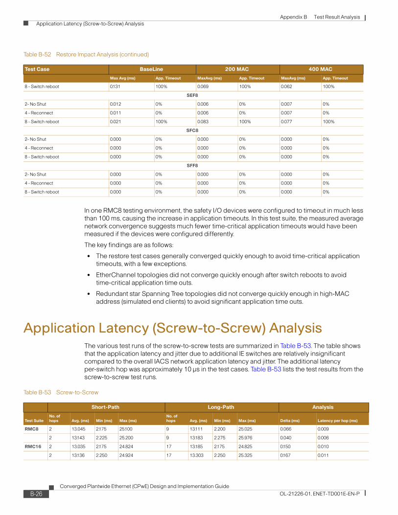
Appendix B Test Result Analysis Application Latency (Screw-to-Screw) Analysis
In one RMC8 testing environment, the safety I/O devices were configured to timeout in much less than 100 ms, causing the increase in application timeouts. In this test suite, the measured average network convergence suggests much fewer time-critical application timeouts would have been measured if the devices were configured differently.
The key findings are as follows:
• The restore test cases generally converged quickly enough to avoid time-critical application timeouts, with a few exceptions.
• EtherChannel topologies did not converge quickly enough after switch reboots to avoid time-critical application time outs.
• Redundant star Spanning Tree topologies did not converge quickly enough in high-MAC address (simulated end clients) to avoid significant application time outs.
Application Latency (Screw-to-Screw) AnalysisThe various test runs of the screw-to-screw tests are summarized in Table B-53. The table shows that the application latency and jitter due to additional IE switches are relatively insignificant compared to the overall IACS network application latency and jitter. The additional latency per-switch hop was approximately 10 μs in the test cases. Table B-53 lists the test results from the screw-to-screw test runs.
8 - Switch reboot 0.131 100% 0.069 100% 0.062 100%
SEF8
2- No Shut 0.012 0% 0.006 0% 0.007 0%
4 - Reconnect 0.011 0% 0.006 0% 0.007 0%
8 - Switch reboot 0.021 100% 0.083 100% 0.077 100%
SFC8
2- No Shut 0.000 0% 0.000 0% 0.000 0%
4 - Reconnect 0.000 0% 0.000 0% 0.000 0%
8 - Switch reboot 0.000 0% 0.000 0% 0.000 0%
SFF8
2- No Shut 0.000 0% 0.000 0% 0.000 0%
4 - Reconnect 0.000 0% 0.000 0% 0.000 0%
8 - Switch reboot 0.000 0% 0.000 0% 0.000 0%
Table B-52 Restore Impact Analysis (continued)
Test Case BaseLine 200 MAC 400 MAC
Max Avg (ms) App. Timeout MaxAvg (ms) App. Timeout MaxAvg (ms) App. Timeout
Table B-53 Screw-to-Screw
Short-Path Long-Path Analysis
Test SuiteNo. of hops Avg. (ms) Min (ms) Max (ms)
No. of hops Avg. (ms) Min (ms) Max (ms) Delta (ms) Latency per hop (ms)
RMC8 2 13.045 2.175 25.100 9 13.111 2.200 25.025 0.066 0.009
2 13.143 2.225 25.200 9 13.183 2.275 25.976 0.040 0.006
RMC16 2 13.035 2.175 24.824 17 13.185 2.175 24.825 0.150 0.010
2 13.136 2.250 24.924 17 13.303 2.250 25.325 0.167 0.011
B-26Converged Plantwide Ethernet (CPwE) Design and Implementation Guide
OL-21226-01, ENET-TD001E-EN-P

Appendix B Test Result Analysis Application Latency (Screw-to-Screw) Analysis
The key findings are as follows:
• The conclusion is that latency and jitter introduced by additional network infrastructure is not significant to I/O type of applications
RMF8 2 13.036 2.175 24.849 9 13.108 2.175 60.076 0.072 0.010
2 13.148 2.225 25.151 9 13.220 2.250 26.300 0.072 0.010
SMC8 3 13.044 2.225 24.825
3 13.175 2.275 24.900 3 13.183 2.275 25.975
SMF8 3 13.036 2.200 24.825
SEC8 3 13.045 2.200 24.826 3 13.035 2.200 24.849
SEF8 3 13.061 2.172 24.825 3 13.134 2.225 26.199
3 13.165 2.251 24.899 3 13.169 2.250 25.175
Table B-53 Screw-to-Screw (continued)
Short-Path Long-Path Analysis
Test SuiteNo. of hops Avg. (ms) Min (ms) Max (ms)
No. of hops Avg. (ms) Min (ms) Max (ms) Delta (ms) Latency per hop (ms)
B-27Converged Plantwide Ethernet (CPwE) Design and Implementation Guide
OL-21226-01, ENET-TD001E-EN-P

Appendix B Test Result Analysis Application Latency (Screw-to-Screw) Analysis
B-28Converged Plantwide Ethernet (CPwE) Design and Implementation Guide
OL-21226-01, ENET-TD001E-EN-P

Converged Plantwide Ethernet (CPwOL-21226-01, ENET-TD001E-EN-P
A P P E N D I X C
Complete Test DataThis appendix provides the data generated from the CPwE solution testing. For an overview of the test approach used and test summary, see Chapter 7, “Testing the CPwE Solution.” For an analysis of these test results, see Appendix B, “Test Result Analysis.”
Test Suite SummaryTable C-1 Test Suite Overview
Test Suite Topology
Spanning Tree Protocol
Uplink Physical Layer
IE Switches
Test Iterations
Network Events
MAC Address cases
Test Runs
Screw to Screw
Test Stream
Mcast Ucast
RMC8 Ring MSTP Copper 8 20 8 3 480 X X
RMC16 Ring MSTP Copper 16 10 8 3 240 X X
RPC8 Ring Rapid-PVST+ Copper 8 20 8 1 (baseline)
160 X
RMF8 Ring MSTP Fiber 8 10 4 3 120 X X
SMC8 Red. Star MSTP Copper 8 10 6 3 180 X X
SMF8 Red. Star MSTP Fiber 8 10 6 3 180 X X
SEC8 Red. Star EtherChannel Copper 8 10 6 3 180 X X X
SEF8 Red. Star EtherChannel Fiber 8 10 6 3 180 X X X
SFC8 Red. Star FlexLinks Copper 8 10 6 3 180 X X
SFF8 Red. Star FlexLinks Fiber 8 10 6 3 180 X X
C-1E) Design and Implementation Guide

Appendix C Complete Test Data RMC8 Test Results
RMC8 Test ResultsThis section provides detailed test results for the test suite with an 8-switch ring topology, MSTP protocol, and copper media uplinks. Figure C-1 depicts the topology and the traffic flows before and after a network disruption.
Figure C-1 RMC8—Break Connection Between IES-7 and IES-8
Table C-2 Test Case Naming
Topology Ring Redundant Star
# of IE Switches 8 Switches 16 Switches 8 Switches
Protocol MSTPRapid PVST+ MSTP EtherChannel Flex Links
Media Uplink Copper Copper Fiber Copper Copper Fiber Copper Fiber Copper Fiber
Shut link RMC8-1 RPC8-1 RMF8-1 RMC16-1 SMC8-1 SMF8-1 SEC8-1 SEF8-1 SFC8-1 SFF8-1
No Shut link RMC8-2 RPC8-2 RMF8-2 RMC16-2 SMC8-2 SMF8-2 SEC8-2 SEF8-2 SFC8-2 SFF8-2
Disconnect RMC8-3 RPC8-3 RMF8-3 RMC16-3 SMC8-3 SMF8-3 SEC8-3 SEF8-3 SFC8-3 SFF8-3
Reconnect RMC8-4 RPC8-4 RMF8-4 RMC16-4 SMC8-4 SMF8-4 SEC8-4 SEF8-4 SFC8-4 SFF8-4
Root down RMC8-5 RPC8-5 RMC16-5
Root Up RMC8-6 RPC8-6 RMC16-6
Stack Master down
RMC8-7 RPC8-7 RMC16-7 SMC8-5 SMF8-5 SEC8-5 SEF8-5 SFC8-5 SFF8-5
Switch Up RMC8-8 RPC8-8 RMC16-8 SMC8-6 SMF8-6 SEC8-6 SEF8-6 SFC8-6 SFF8-6
Number of test runs
480 160 120 240 180 180 180 180 180 180
Total test runs: 1000 1080
Grand total: 2080
VLAN 1710.17.10.x
STP BlockLink Disruption
After
Before
Fa1/1 Ixia 3/2
8
7
4 5
Fa1/2
Fa1/3
Ixia 3/1
Ixia 3/3
Fa1/2
Ixia 3/4
IXIA
IXIA
IES-1
IES-7IES-2
IES-8
CZ-3750
IES-3
IES-4 IES-5
IES-6
.10
.11
.12
.13.14
.15
.16
.17
2278
45
C-2Converged Plantwide Ethernet (CPwE) Design and Implementation Guide
OL-21226-01, ENET-TD001E-EN-P

Appendix C Complete Test Data RMC8 Test Results
Table C-3 Test Case RMC8-1—Bring Down Link from 7 to 8 (Software)
Baseline 200 MAC 400 MAC
Run 7 to 8 8 to 7 4 to 5 5 to 4
Peer-to-Peer Timeout 7 to 8 8 to 7 4 to 5 5 to 4
Peer-to-Peer Timeout 7 to 8 8 to 7 4 to 5 5 to 4
Peer-to-Peer Timeout
1 0.804 0.804 0.800 0.794 Yes 0.467 0.515 0.434 0.427 Yes 0.454 0.492 0.406 0.401 Yes
2 1.793 1.793 0.423 0.414 Yes 0.424 0.424 0.407 0.401 Yes 0.455 0.455 0.429 0.426 Yes
3 1.307 1.307 0.806 0.801 Yes 0.863 0.863 0.814 0.808 Yes 1.209 1.209 0.829 0.821 Yes
4 1.349 1.349 0.405 0.398 Yes 1.113 1.114 0.791 0.785 Yes 0.483 0.483 0.438 0.430 Yes
5 1.194 1.194 0.398 0.394 Yes 2.350 2.362 0.403 0.397 Yes 2.382 2.382 0.405 0.400 Yes
6 0.848 0.848 0.422 0.419 Yes 0.855 0.854 0.805 0.799 Yes 1.368 1.368 0.832 0.825 Yes
7 1.146 1.146 0.386 0.380 Yes 1.536 1.536 0.410 0.402 Yes 0.452 0.452 0.431 0.423 Yes
8 0.813 0.814 0.809 0.803 Yes 0.935 0.935 0.833 0.825 Yes 0.439 0.439 0.414 0.406 Yes
9 1.012 1.012 0.388 0.385 Yes 0.816 0.816 0.801 0.795 Yes 2.346 2.346 0.399 0.394 Yes
10 1.649 1.650 0.789 0.785 Yes 0.900 0.900 0.423 0.416 Yes 0.426 0.426 0.403 0.396 Yes
11 0.462 0.418 0.386 0.397 Yes 1.332 1.303 0.818 0.830 Yes 0.893 0.893 0.814 0.827 Yes
12 1.154 1.129 0.821 0.829 Yes 0.857 0.857 0.818 0.821 Yes 0.500 0.500 0.421 0.423 Yes
13 0.943 0.936 0.812 0.836 Yes 0.966 0.966 0.808 0.813 Yes 1.784 1.784 0.810 0.820 Yes
14 0.511 0.499 0.410 0.415 Yes 1.505 1.505 0.790 0.795 Yes 0.889 0.889 0.820 0.826 Yes
15 0.797 0.786 0.388 0.413 Yes 1.380 1.380 0.793 0.803 Yes 0.474 0.474 0.406 0.413 Yes
16 0.509 0.490 0.401 0.407 Yes 1.587 1.587 0.801 0.809 Yes 1.293 1.293 0.425 0.431 Yes
17 0.496 0.481 0.391 0.394 Yes 1.396 1.396 0.808 0.809 Yes 0.891 0.891 0.812 0.819 Yes
18 0.512 0.505 0.411 0.418 Yes 0.627 0.627 0.399 0.405 Yes 0.780 0.780 0.436 0.438 Yes
19 1.390 1.365 0.806 0.813 Yes 0.508 0.508 0.415 0.417 Yes 1.754 1.754 0.831 0.834 Yes
20 0.848 0.829 0.788 0.796 Yes 1.595 1.595 0.803 0.806 Yes 0.494 0.494 0.432 0.438 Yes
Average
0.977 0.968 0.562 0.565 1.101 1.102 0.669 0.668 0.990 0.560 0.560
Std Dev.
0.392 0.397 0.203 0.204 0.481 0.479 0.193 0.195 0.641 0.197 0.200
Table C-4 Test Case RMC8-2—Bring Link Up from 7 to 8 (Software)
Baseline 200 MAC 400 MAC
Run 7 to 8 8 to 7 4 to 5 5 to 4
Peer-to-Peer Timeout 7 to 8 8 to 7 4 to 5 5 to 4
Peer-to-Peer Timeout 7 to 8 8 to 7 4 to 5 5 to 4
Peer-to-Peer Timeout
1 0.010 0.014 0.025 0.009 No 0.017 0.022 0.043 0.034 No 0.026 0.027 0.052 0.044 No
2 0.013 0.015 0.037 0.013 No 0.018 0.023 0.044 0.033 No 0.025 0.027 0.050 0.046 No
3 0.010 0.015 0.037 0.007 No 0.019 0.020 0.042 0.033 No 0.023 0.027 0.051 0.048 No
4 0.010 0.017 0.035 0.008 No 0.016 0.023 0.041 0.033 No 0.022 0.028 0.048 0.044 No
5 0.012 0.014 0.034 0.011 No 0.019 0.021 0.038 0.031 No 0.026 0.030 0.047 0.042 No
6 0.010 0.015 0.020 0.009 No 0.019 0.023 0.041 0.029 No 0.024 0.030 0.050 0.043 No
7 0.012 0.015 0.026 0.013 No 0.016 0.022 0.042 0.029 No 0.022 0.029 0.047 0.040 No
8 0.012 0.014 0.017 0.011 No 0.019 0.023 0.042 0.034 No 0.023 0.032 0.052 0.045 No
9 0.012 0.015 0.027 0.012 No 0.016 0.026 0.037 0.025 No 0.024 0.030 0.051 0.044 No
10 0.010 0.017 0.021 0.009 No 0.016 0.020 0.037 0.025 No 0.025 0.028 0.048 0.043 No
11 0.019 0.010 0.071 0.030 Yes 0.031 0.021 0.166 0.166 Yes 0.036 0.024 0.127 0.064 Yes
12 0.032 0.011 0.072 0.037 Yes 0.031 0.019 0.170 0.170 Yes 0.035 0.023 0.184 0.184 Yes
C-3Converged Plantwide Ethernet (CPwE) Design and Implementation Guide
OL-21226-01, ENET-TD001E-EN-P

Appendix C Complete Test Data RMC8 Test Results
13 0.022 0.013 0.041 0.042 Yes 0.053 0.020 0.170 0.170 Yes 0.062 0.024 0.133 0.087 Yes
14 0.031 0.010 0.071 0.038 Yes 0.032 0.019 0.069 0.063 Yes 0.036 0.024 0.177 0.177 Yes
15 0.033 0.010 0.071 0.034 No 0.053 0.017 0.170 0.170 Yes 0.039 0.024 0.187 0.187 Yes
16 0.031 0.013 0.070 0.035 Yes 0.055 0.018 0.167 0.167 Yes 0.036 0.030 0.128 0.076 Yes
17 0.031 0.010 0.072 0.025 Yes 0.055 0.020 0.190 0.190 Yes 0.035 0.025 0.178 0.178 Yes
18 0.036 0.011 0.075 0.038 Yes 0.053 0.017 0.119 0.049 Yes 0.036 0.025 0.189 0.189 Yes
19 0.035 0.010 0.091 0.091 Yes 0.055 0.018 0.177 0.177 Yes 0.064 0.024 0.191 0.191 Yes
20 0.020 0.010 0.123 0.123 Yes 0.030 0.013 0.147 0.077 Yes 0.036 0.023 0.196 0.197 Yes
Average
0.020 0.013 0.052 0.030 0.031 0.020 0.098 0.085 0.033 0.027 0.109 0.098
Std Dev.
0.010 0.003 0.029 0.030 0.016 0.003 0.063 0.067 0.012 0.003 0.064 0.067
Table C-4 Test Case RMC8-2—Bring Link Up from 7 to 8 (Software) (continued)
Baseline 200 MAC 400 MAC
Run 7 to 8 8 to 7 4 to 5 5 to 4
Peer-to-Peer Timeout 7 to 8 8 to 7 4 to 5 5 to 4
Peer-to-Peer Timeout 7 to 8 8 to 7 4 to 5 5 to 4
Peer-to-Peer Timeout
C-4Converged Plantwide Ethernet (CPwE) Design and Implementation Guide
OL-21226-01, ENET-TD001E-EN-P

Appendix C Complete Test Data RMC8 Test Results
Table C-5 Test Case RMC8-3—Disconnect Cable from 7 to 8 (Physical)
Baseline 200 MAC 400 MAC
Run 7 to 8 8 to 7 4 to 5 5 to 4
Peer-to-Peer Timeout 7 to 8 8 to 7 4 to 5 5 to 4
Peer-to-Peer Timeout 7 to 8 8 to 7 4 to 5 5 to 4
Peer-to-Peer Timeout
1 1.392 1.392 0.406 0.400 Yes 0.446 0.460 0.427 0.419 Yes 0.994 1.067 0.435 0.430 Yes
2 1.363 1.363 0.409 0.404 Yes 0.669 0.684 0.405 0.398 Yes 0.581 0.597 0.405 0.399 Yes
3 0.799 0.799 0.792 0.788 Yes 1.025 1.025 0.406 0.400 Yes 1.759 1.759 0.397 0.393 Yes
4 1.178 1.178 0.781 0.775 Yes 0.427 0.439 0.410 0.405 Yes 2.176 2.176 0.815 0.808 Yes
5 0.783 0.783 0.778 0.773 Yes 0.538 0.552 0.424 0.418 Yes 1.700 1.700 0.429 0.422 Yes
6 1.101 1.101 0.385 0.380 Yes 0.807 0.807 0.794 0.786 Yes 2.348 2.348 0.422 0.417 Yes
7 1.750 1.751 0.800 0.791 Yes 0.422 0.430 0.413 0.404 Yes 0.872 0.872 0.831 0.825 Yes
8 1.863 1.863 0.814 0.807 Yes 0.812 0.805 0.788 0.782 Yes 0.843 0.843 0.797 0.790 Yes
9 1.691 1.691 0.406 0.400 Yes 0.807 0.807 0.788 0.786 Yes 0.842 0.842 0.796 0.793 Yes
10 1.722 1.722 0.804 0.798 Yes 0.802 0.802 0.786 0.782 Yes 2.054 2.075 0.813 0.808 Yes
11 1.447 1.413 0.803 0.813 Yes 0.511 0.494 0.408 0.418 Yes 0.492 0.474 0.398 0.412 Yes
12 0.430 0.406 0.385 0.391 Yes 0.967 0.967 0.799 0.809 Yes 0.871 0.871 0.807 0.814 Yes
13 0.483 0.468 0.379 0.384 Yes 1.091 1.091 0.820 0.826 Yes 0.882 0.882 0.813 0.819 Yes
14 0.923 0.911 0.413 0.419 Yes 1.746 1.746 0.821 0.827 Yes 0.864 0.864 0.796 0.806 Yes
15 1.056 1.036 0.382 0.387 Yes 0.852 0.852 0.814 0.820 Yes 1.426 1.426 0.790 0.797 Yes
16 0.964 0.932 0.842 0.844 Yes 0.454 0.446 0.386 0.392 Yes 1.125 1.125 0.798 0.805 Yes
17 0.664 0.409 0.381 0.384 Yes 0.583 0.574 0.396 0.403 Yes 1.314 1.314 0.414 0.421 Yes
18 0.463 0.441 0.414 0.417 Yes 0.566 0.556 0.397 0.404 Yes 0.499 0.487 0.413 0.449 Yes
19 1.001 0.821 0.790 0.797 Yes 0.853 0.853 0.390 0.394 Yes 0.483 0.470 0.400 0.409 Yes
20 1.281 0.414 0.387 0.389 Yes 0.460 0.451 0.390 0.397 Yes 0.896 0.896 0.822 0.829 Yes
Average
1.118 1.045 0.578 0.577 0.742 0.742 0.563 0.564 1.151 1.154 0.629 0.632
Std Dev.
0.443 0.489 0.208 0.206 0.317 0.317 0.200 0.201 0.576 0.578 0.202 0.200
Table C-6 Test Case RMC8-4—Reconnect Cable from 7 to 8 (Physical)
Baseline 200 MAC 400 MAC
Run 7 to 8 8 to 7 4 to 5 5 to 4
Peer-to-Peer Timeout 7 to 8 8 to 7 4 to 5 5 to 4
Peer-to-Peer Timeout 7 to 8 8 to 7 4 to 5 5 to 4
Peer-to-Peer Timeout
1 1.392 1.392 0.406 0.400 Yes 0.446 0.460 0.427 0.419 Yes 0.994 1.067 0.435 0.430 Yes
2 1.363 1.363 0.409 0.404 Yes 0.669 0.684 0.405 0.398 Yes 0.581 0.597 0.405 0.399 Yes
3 0.799 0.799 0.792 0.788 Yes 1.025 1.025 0.406 0.400 Yes 1.759 1.759 0.397 0.393 Yes
4 1.178 1.178 0.781 0.775 Yes 0.427 0.439 0.410 0.405 Yes 2.176 2.176 0.815 0.808 Yes
5 0.783 0.783 0.778 0.773 Yes 0.538 0.552 0.424 0.418 Yes 1.700 1.700 0.429 0.422 Yes
6 1.101 1.101 0.385 0.380 Yes 0.807 0.807 0.794 0.786 Yes 2.348 2.348 0.422 0.417 Yes
7 1.750 1.751 0.800 0.791 Yes 0.422 0.430 0.413 0.404 Yes 0.872 0.872 0.831 0.825 Yes
8 1.863 1.863 0.814 0.807 Yes 0.812 0.805 0.788 0.782 Yes 0.843 0.843 0.797 0.790 Yes
9 1.691 1.691 0.406 0.400 Yes 0.807 0.807 0.788 0.786 Yes 0.842 0.842 0.796 0.793 Yes
10 1.722 1.722 0.804 0.798 Yes 0.802 0.802 0.786 0.782 Yes 2.054 2.075 0.813 0.808 Yes
11 1.447 1.413 0.803 0.813 Yes 0.511 0.494 0.408 0.418 Yes 0.492 0.474 0.398 0.412 Yes
12 0.430 0.406 0.385 0.391 Yes 0.967 0.967 0.799 0.809 Yes 0.871 0.871 0.807 0.814 Yes
C-5Converged Plantwide Ethernet (CPwE) Design and Implementation Guide
OL-21226-01, ENET-TD001E-EN-P
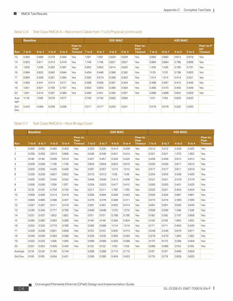
Appendix C Complete Test Data RMC8 Test Results
13 0.483 0.468 0.379 0.384 Yes 1.091 1.091 0.820 0.826 Yes 0.882 0.882 0.813 0.819 Yes
14 0.923 0.911 0.413 0.419 Yes 1.746 1.746 0.821 0.827 Yes 0.864 0.864 0.796 0.806 Yes
15 1.056 1.036 0.382 0.387 Yes 0.852 0.852 0.814 0.820 Yes 1.426 1.426 0.790 0.797 Yes
16 0.964 0.932 0.842 0.844 Yes 0.454 0.446 0.386 0.392 Yes 1.125 1.125 0.798 0.805 Yes
17 0.664 0.409 0.381 0.384 Yes 0.583 0.574 0.396 0.403 Yes 1.314 1.314 0.414 0.421 Yes
18 0.463 0.441 0.414 0.417 Yes 0.566 0.556 0.397 0.404 Yes 0.499 0.487 0.413 0.449 Yes
19 1.001 0.821 0.790 0.797 Yes 0.853 0.853 0.390 0.394 Yes 0.483 0.470 0.400 0.409 Yes
20 1.281 0.414 0.387 0.389 Yes 0.460 0.451 0.390 0.397 Yes 0.896 0.896 0.822 0.829 Yes
Average
1.118 1.045 0.578 0.577 0.742 0.742 0.563 0.564 1.151 1.154 0.629 0.632
Std Dev.
0.443 0.489 0.208 0.206 0.317 0.317 0.200 0.201 0.576 0.578 0.202 0.200
Table C-7 Test Case RMC8-5—Root Bridge Down
Baseline 200 MAC 400 MAC
Run 7 to 8 8 to 7 4 to 5 5 to 4
Peer-to-Peer Timeout 7 to 8 8 to 7 4 to 5 5 to 4
Peer-to-Peer Timeout 7 to 8 8 to 7 4 to 5 5 to 4
Peer-to-Peer Timeout
1 0.000 0.000 0.400 0.402 Yes 0.220 0.220 0.414 0.409 Yes 0.012 0.012 0.429 0.425 Yes
2 0.258 0.258 0.813 0.806 Yes 0.045 0.045 0.421 0.414 Yes 0.021 0.021 1.379 1.383 Yes
3 0.146 0.146 0.509 0.510 Yes 0.457 0.457 0.430 0.425 Yes 0.458 0.458 0.912 0.912 Yes
4 0.006 0.006 1.728 1.728 Yes 0.804 0.804 0.823 0.815 Yes 0.030 0.029 0.817 0.810 Yes
5 0.000 0.000 0.425 0.426 Yes 0.057 0.057 1.213 1.213 Yes 0.517 0.517 0.811 0.819 Yes
6 0.229 0.229 0.827 0.822 Yes 0.013 0.013 1.129 1.129 Yes 0.204 0.204 0.428 0.420 Yes
7 0.005 0.005 0.540 0.542 Yes 0.849 0.849 0.413 0.406 Yes 0.021 0.021 2.016 2.016 Yes
8 0.006 0.006 1.256 1.257 Yes 0.024 0.023 0.417 0.412 Yes 0.000 0.000 0.421 0.425 Yes
9 0.135 0.135 0.704 0.704 Yes 0.011 0.011 1.765 1.765 Yes 0.022 0.021 0.403 0.404 Yes
10 0.006 0.006 0.414 0.416 Yes 0.094 0.094 0.449 0.443 Yes 0.505 0.504 0.961 0.961 Yes
11 0.684 0.685 0.396 0.407 Yes 0.476 0.476 0.399 0.411 Yes 0.074 0.074 2.565 2.565 Yes
12 0.297 0.297 0.411 0.419 Yes 0.391 0.391 0.402 0.414 Yes 0.091 0.091 0.930 0.930 Yes
13 0.245 0.245 0.777 0.785 Yes 0.846 0.846 1.270 1.274 Yes 0.506 0.506 1.348 1.348 Yes
14 0.037 0.037 1.852 1.852 Yes 0.151 0.151 0.789 0.795 Yes 0.180 0.180 0.797 0.808 Yes
15 0.080 0.080 0.383 0.386 Yes 0.148 0.148 0.394 0.404 Yes 0.159 0.159 1.855 1.855 Yes
16 0.202 0.202 0.774 0.785 Yes 0.095 0.096 1.214 1.214 Yes 0.171 0.171 0.403 0.435 Yes
17 0.208 0.208 0.801 0.809 Yes 0.153 0.153 0.402 0.413 Yes 0.249 0.249 0.679 0.811 Yes
18 0.049 0.049 0.384 0.389 Yes 0.235 0.235 0.383 0.394 Yes 0.278 0.279 1.283 1.283 Yes
19 0.032 0.032 1.006 1.006 Yes 0.566 0.566 0.393 0.399 Yes 0.170 0.170 0.394 0.404 Yes
20 0.051 0.052 0.409 0.435 Yes 0.132 0.132 1.159 1.159 Yes 0.066 0.066 0.153 0.160 Yes
Average 0.134 0.134 0.740 0.744 0.288 0.288 0.714 0.715 0.187 0.187 0.949 0.959
Std Dev. 0.165 0.165 0.434 0.431 0.285 0.285 0.424 0.423 0.179 0.179 0.629 0.625
Table C-6 Test Case RMC8-4—Reconnect Cable from 7 to 8 (Physical) (continued)
Baseline 200 MAC 400 MAC
Run 7 to 8 8 to 7 4 to 5 5 to 4
Peer-to-Peer Timeout 7 to 8 8 to 7 4 to 5 5 to 4
Peer-to-Peer Timeout 7 to 8 8 to 7 4 to 5 5 to 4
Peer-to-Peer Timeout
C-6Converged Plantwide Ethernet (CPwE) Design and Implementation Guide
OL-21226-01, ENET-TD001E-EN-P

Appendix C Complete Test Data RMC8 Test Results
Table C-8 Test Case RMC8-6—Root Bridge Up
Baseline 200 MAC 400 MAC
Run 7 to 8 8 to 7 4 to 5 5 to 4
Peer-to-Peer Timeout 7 to 8 8 to 7 4 to 5 5 to 4
Peer-to-Peer Timeout 7 to 8 8 to 7 4 to 5 5 to 4
Peer-to-Peer Timeout
1 0.020 0.020 0.220 0.220 Yes 0.465 0.465 0.468 0.453 Yes 0.595 0.595 0.710 0.697 Yes
2 0.022 0.022 0.900 0.901 Yes 0.038 0.038 0.733 0.720 Yes 0.045 0.045 0.296 0.300 Yes
3 0.022 0.022 0.024 0.024 Yes 0.038 0.038 0.399 0.391 Yes 0.062 0.062 0.072 0.062 Yes
4 0.021 0.021 0.045 0.017 Yes 0.034 0.034 0.540 0.544 Yes 0.049 0.049 0.634 0.643 Yes
5 0.019 0.019 0.045 0.045 Yes 0.042 0.042 0.313 0.304 Yes 0.060 0.060 0.752 0.739 Yes
6 0.020 0.020 0.860 0.853 Yes 0.884 0.884 0.905 0.885 Yes 0.276 0.276 0.284 0.269 Yes
7 0.399 0.399 0.429 0.400 Yes 0.547 0.547 0.563 0.548 Yes 0.133 0.133 0.163 0.148 Yes
8 0.022 0.022 0.024 0.024 No 0.042 0.042 0.702 0.691 Yes 0.067 0.067 0.073 0.058 Yes
9 0.022 0.022 0.308 0.308 Yes 0.040 0.040 0.061 0.053 Yes 0.060 0.060 0.063 0.058 Yes
10 0.023 0.023 0.023 0.023 No 0.039 0.040 0.231 0.221 Yes 0.045 0.045 0.305 0.305 Yes
11 0.028 0.028 0.890 0.867 Yes 0.102 0.102 0.464 0.465 Yes 0.175 0.175 0.139 0.144 Yes
12 0.036 0.036 1.070 1.042 Yes 0.061 0.061 0.118 0.121 Yes 0.878 0.878 0.881 0.881 Yes
13 0.032 0.032 1.060 1.045 Yes 0.051 0.051 0.121 0.120 Yes 0.829 0.829 0.878 0.878 Yes
14 0.105 0.105 0.650 0.650 Yes 0.108 0.108 0.197 0.158 Yes 0.146 0.146 0.890 0.890 Yes
15 0.033 0.033 0.072 0.040 Yes 0.119 0.119 0.226 0.226 Yes 0.069 0.069 0.069 0.069 Yes
16 0.363 0.363 0.513 0.542 Yes 0.098 0.098 0.220 0.220 Yes 0.074 0.074 1.006 1.006 Yes
17 0.053 0.053 0.953 0.984 Yes 0.239 0.239 0.282 0.282 Yes 0.120 0.120 1.078 1.079 Yes
18 0.395 0.395 0.501 0.532 Yes 0.057 0.057 0.238 0.238 Yes 0.084 0.084 0.214 0.182 Yes
19 0.032 0.032 1.006 1.006 Yes 0.058 0.058 0.126 0.129 Yes 0.066 0.066 0.153 0.160 Yes
20 0.032 0.032 0.093 0.068 Yes 0.094 0.094 0.848 0.848 Yes 0.110 0.110 0.538 0.538 Yes
Average 0.085 0.085 0.484 0.479 0.158 0.158 0.388 0.381 0.197 0.197 0.460 0.455
Std Dev. 0.131 0.131 0.405 0.408 0.222 0.222 0.255 0.253 0.257 0.257 0.358 0.361
Table C-9 Test Case RMC8-7—Stack Master Down
Baseline 200 MAC 400 MAC
Run 7 to 8 8 to 7 4 to 5 5 to 4
Peer-to-Peer Timeout 7 to 8 8 to 7 4 to 5 5 to 4
Peer-to-Peer Timeout 7 to 8 8 to 7 4 to 5 5 to 4
Peer-to-Peer Timeout
1 0.020 0.020 1.362 1.362 Yes 0.037 0.037 0.821 0.816 Yes 0.000 0.000 1.968 1.968 Yes
2 0.010 0.010 0.403 0.396 Yes 0.000 0.000 1.264 1.264 Yes 0.359 0.359 0.422 0.418 Yes
3 0.000 0.000 0.810 0.805 Yes 0.395 0.395 0.820 0.812 Yes 0.000 0.000 1.374 1.374 Yes
4 0.580 0.580 0.410 0.407 Yes 0.000 0.000 0.832 0.832 Yes 0.038 0.038 0.854 0.846 Yes
5 0.000 0.000 0.804 0.799 Yes 0.021 0.021 0.413 0.408 Yes 0.000 0.000 2.401 2.401 Yes
6 0.010 0.010 0.416 0.413 Yes 0.000 0.000 2.734 2.734 Yes 0.507 0.507 0.492 0.482 Yes
7 0.000 0.000 0.814 0.815 Yes 0.763 0.763 0.442 0.438 Yes 0.000 0.000 0.799 0.804 Yes
8 0.013 0.013 0.824 0.818 Yes 0.000 0.000 2.748 2.748 Yes 0.027 0.026 0.843 0.840 Yes
9 0.000 0.000 1.197 1.197 Yes 0.801 0.801 0.425 0.418 Yes 0.000 0.000 0.408 0.409 Yes
10 0.048 0.048 1.183 1.175 Yes 0.000 0.000 0.427 0.430 Yes 1.514 1.514 0.449 0.439 Yes
11 0.081 0.081 0.804 0.812 Yes 0.107 0.107 0.802 0.813 Yes 0.705 0.705 0.418 0.429 Yes
12 0.000 0.000 0.404 0.404 Yes 0.000 0.000 0.411 0.433 Yes 0.000 0.000 0.587 0.587 Yes
13 0.791 0.791 0.370 0.378 Yes 0.883 0.883 0.393 0.404 Yes 0.534 0.534 0.385 0.402 Yes
C-7Converged Plantwide Ethernet (CPwE) Design and Implementation Guide
OL-21226-01, ENET-TD001E-EN-P

Appendix C Complete Test Data RMC8 Test Results
14 0.000 0.000 0.813 0.817 Yes 0.000 0.000 0.464 0.464 Yes 0.000 0.000 0.459 0.459 Yes
15 0.225 0.225 0.374 0.379 Yes 0.089 0.089 0.399 0.412 Yes 0.119 0.119 0.385 0.399 Yes
16 0.000 0.000 1.257 1.257 Yes 0.000 0.000 0.423 0.448 Yes 0.000 0.000 0.442 0.462 Yes
17 0.043 0.043 0.377 0.385 Yes 0.105 0.105 0.409 0.419 Yes 0.115 0.115 0.406 0.415 Yes
18 0.000 0.000 1.737 1.736 Yes 0.000 0.000 1.147 1.147 Yes 0.000 0.000 0.421 0.439 Yes
19 0.047 0.047 0.381 0.389 Yes 0.093 0.093 0.804 0.836 Yes 0.211 0.211 0.817 0.828 Yes
20 0.000 0.000 0.805 0.812 Yes 0.000 0.000 0.408 0.429 Yes 0.000 0.000 1.222 1.222 Yes
Average 0.093 0.093 0.777 0.778 0.165 0.165 0.829 0.835 0.206 0.206 0.778 0.781
Std Dev. 0.212 0.212 0.399 0.398 0.295 0.295 0.705 0.703 0.376 0.376 0.563 0.561
Table C-10 Test Case RMC8-8—Adding Switch Back to Stack
Baseline 200 MAC 400 MAC
Run 7 to 8 8 to 7 4 to 5 5 to 4
Peer-to-Peer Timeout 7 to 8 8 to 7 4 to 5 5 to 4
Peer-to-Peer Timeout 7 to 8 8 to 7 4 to 5 5 to 4
Peer-to-Peer Timeout
1 0.000 0.000 0.006 0.042 No 0.027 0.027 0.027 0.011 No 0.000 0.000 0.013 0.013 No
2 0.022 0.022 0.024 0.006 No 0.000 0.000 0.011 0.007 No 0.033 0.033 0.035 0.016 No
3 0.000 0.000 0.006 0.006 No 0.026 0.026 0.021 0.009 No 0.000 0.000 0.010 0.010 No
4 0.019 0.019 0.015 0.008 No 0.000 0.000 0.010 0.006 No 0.033 0.033 0.032 0.016 No
5 0.000 0.000 0.007 0.007 No 0.026 0.026 0.019 0.010 No 0.000 0.000 0.008 0.008 No
6 0.020 0.020 0.024 0.006 No 0.000 0.000 0.009 0.006 No 0.033 0.033 0.034 0.016 No
7 0.000 0.000 0.008 0.008 Yes 0.040 0.040 0.039 0.039 No 0.000 0.000 0.013 0.012 No
8 0.022 0.022 0.024 0.009 Yes 0.000 0.000 0.010 0.006 No 0.034 0.034 0.038 0.017 No
9 0.000 0.000 0.008 0.047 Yes 0.027 0.028 0.019 0.011 No 0.000 0.000 0.013 0.006 No
10 0.022 0.022 0.026 0.008 Yes 0.000 0.000 0.009 0.006 No 0.035 0.035 0.033 0.016 No
11 0.033 0.033 0.049 0.037 Yes 0.049 0.049 0.095 0.076 Yes 0.058 0.058 0.137 0.085 Yes
12 0.000 0.000 0.134 0.100 Yes 0.000 0.000 0.175 0.175 Yes 0.000 0.000 0.177 0.177 Yes
13 0.032 0.032 0.051 0.037 Yes 0.169 0.169 0.183 0.184 Yes 0.057 0.057 0.093 0.087 Yes
14 0.000 0.000 0.109 0.093 Yes 0.000 0.000 0.172 0.172 Yes 0.000 0.000 0.184 0.184 Yes
15 0.033 0.033 0.048 0.040 Yes 0.051 0.051 0.137 0.074 Yes 0.056 0.056 0.158 0.158 Yes
16 0.000 0.000 0.126 0.092 Yes 0.000 0.000 0.079 0.057 Yes 0.000 0.000 0.173 0.173 Yes
17 0.028 0.028 0.048 0.038 Yes 0.050 0.050 0.093 0.072 Yes 0.185 0.185 0.194 0.194 Yes
18 0.000 0.000 0.137 0.102 Yes 0.000 0.000 0.100 0.059 Yes 0.000 0.000 0.168 0.168 Yes
19 0.033 0.033 0.049 0.039 Yes 0.181 0.181 0.181 0.181 Yes 0.057 0.057 0.140 0.080 Yes
20 0.000 0.000 0.121 0.092 Yes 0.000 0.000 0.176 0.176 Yes 0.000 0.000 0.032 0.058 Yes
Average 0.013 0.013 0.051 0.041 0.032 0.032 0.078 0.067 0.029 0.029 0.084 0.075
Std Dev. 0.014 0.014 0.047 0.036 0.052 0.052 0.069 0.070 0.043 0.043 0.072 0.073
Table C-9 Test Case RMC8-7—Stack Master Down (continued)
Baseline 200 MAC 400 MAC
Run 7 to 8 8 to 7 4 to 5 5 to 4
Peer-to-Peer Timeout 7 to 8 8 to 7 4 to 5 5 to 4
Peer-to-Peer Timeout 7 to 8 8 to 7 4 to 5 5 to 4
Peer-to-Peer Timeout
C-8Converged Plantwide Ethernet (CPwE) Design and Implementation Guide
OL-21226-01, ENET-TD001E-EN-P

Appendix C Complete Test Data RMC16 Test Results
RMC16 Test ResultsThis section provides detailed test results for the test suite with a 16-switch ring topology, MSTP protocol, and copper media uplinks. Figure C-2 depicts the topology and the traffic flows before and after a network disruption.
Figure C-2 RMC 16—Break Connection between IES-7 and IES-8
Table C-11 Test Case RMC16-1—Bring Down Link from 7 to 8 (Software)
Baseline 200 MAC 400 MAC
Run 7 to 8 8 to 7 4 to 5 5 to 4Peer-to-Peer Timeout 7 to 8 8 to 7 4 to 5 5 to 4
Peer-to-Peer Timeout 7 to 8 8 to 7 4 to 5 5 to 4
Peer-to-Peer Timeout
1 1.045 1.045 0.425 0.419 Yes 1.111 1.111 0.830 0.825 Yes 1.728 1.728 0.814 0.807 Yes
2 2.422 2.422 0.813 0.808 Yes 1.055 1.055 0.431 0.424 Yes 1.625 1.625 0.835 0.827 Yes
3 1.826 1.826 0.806 0.801 Yes 1.393 1.393 0.796 0.790 Yes 2.316 2.316 0.418 0.410 Yes
4 1.601 1.601 0.823 0.818 Yes 1.883 1.883 0.435 0.431 Yes 1.288 1.288 0.412 0.404 Yes
5 1.998 1.998 0.410 0.404 Yes 1.277 1.277 0.426 0.421 Yes 1.803 1.803 0.822 0.817 Yes
6 1.828 1.805 0.387 0.396 Yes 1.091 0.953 0.825 0.827 Yes 0.960 0.946 0.811 0.815 Yes
7 1.679 1.679 0.784 0.789 Yes 2.470 2.470 0.822 0.828 Yes 2.107 2.107 0.403 0.409 Yes
8 2.261 2.261 0.410 0.415 Yes 2.755 2.755 0.810 0.815 Yes 2.717 2.717 0.806 0.810 Yes
VLAN 1710.17.10.x
Fa1/1 Ixia 3/2
8
7Fa1/2
Ixia 3/1
IXIA
4 5Fa1/3
Ixia 3/3
Fa1/2
Ixia 3/4IXIA
IES-1
IES-9
IES-2
IES-10
IES-3
IES-11
IES-12
IES-4 IES-5
IES-13
IES-14
IES-6
IES-15
IES-16
IES-7
IES-8
CZ-3750
STP BlockLink Disruption
After
Before
.17.10
.18
.11
.19
.12
.20
.21
.13.14
.22
.23
.15
.24
.25
.16
2276
61
2278
46
C-9Converged Plantwide Ethernet (CPwE) Design and Implementation Guide
OL-21226-01, ENET-TD001E-EN-P

Appendix C Complete Test Data RMC16 Test Results
9 1.164 1.164 0.805 0.804 Yes 2.167 2.167 0.423 0.425 Yes 1.670 1.670 0.804 0.812 Yes
10 2.112 2.112 0.797 0.806 Yes 1.355 1.355 0.401 0.406 Yes 0.483 0.483 0.424 0.429 Yes
Average
1.794 1.791 0.646 0.646 1.656 1.642 0.620 0.619 1.670 1.668 0.655 0.654
Std Dev.
0.443 0.443 0.205 0.205 0.620 0.636 0.208 0.209 0.648 0.650 0.207 0.208
Table C-12 Test Case RMC16-2—Bring Link Up from 7 to 8 (Software)
Baseline 200 MAC 400 MAC
Run 7 to 8 8 to 7 4 to 5 5 to 4
Peer-to-Peer Timeout 7 to 8 8 to 7 4 to 5 5 to 4
Peer-to-Peer Timeout 7 to 8 8 to 7 4 to 5 5 to 4
Peer-to-Peer Timeout
1 0.010 0.015 0.024 0.007 No 0.017 0.025 0.033 0.026 No 0.024 0.031 0.051 0.032 No
2 0.010 0.017 0.010 0.006 No 0.017 0.023 0.035 0.026 No 0.024 0.030 0.048 0.035 No
3 0.010 0.017 0.014 0.008 No 0.016 0.025 0.035 0.023 No 0.042 0.043 0.053 0.035 No
4 0.010 0.016 0.014 0.006 No 0.017 0.025 0.029 0.020 No 0.023 0.030 0.054 0.040 No
5 0.010 0.018 0.028 0.005 No 0.017 0.022 0.046 0.036 No 0.024 0.028 0.042 0.029 No
6 0.015 0.010 0.007 0.014 No 0.023 0.017 0.029 0.039 No 0.031 0.024 0.056 0.057 No
7 0.016 0.010 0.007 0.020 No 0.022 0.017 0.038 0.045 No 0.034 0.024 0.055 0.055 No
8 0.015 0.010 0.007 0.035 No 0.035 0.035 0.023 0.033 No 0.029 0.024 0.054 0.055 No
9 0.015 0.010 0.007 0.018 No 0.026 0.017 0.038 0.044 No 0.030 0.023 0.052 0.053 No
10 0.016 0.015 0.007 0.030 No 0.021 0.017 0.027 0.038 No 0.028 0.024 0.063 0.063 No
Average 0.013 0.014 0.012 0.015 0.021 0.022 0.033 0.033 0.029 0.028 0.053 0.045
Std Dev. 0.003 0.003 0.008 0.011 0.006 0.006 0.007 0.009 0.006 0.006 0.005 0.012
Table C-13 Test Case RMC16-3—Disconnect Cable from 7 to 8 (Physical)
Baseline 200 MAC 400 MAC
Run 7 to 8 8 to 7 4 to 5 5 to 4
Peer-to-Peer Timeout 7 to 8 8 to 7 4 to 5 5 to 4
Peer-to-Peer Timeout 7 to 8 8 to 7 4 to 5 5 to 4
Peer-to-Peer Timeout
1 1.386 1.386 0.806 0.803 Yes 1.330 1.330 0.788 0.782 Yes 1.684 1.684 0.812 0.805 Yes
2 1.871 1.871 0.805 0.802 Yes 1.210 1.210 0.811 0.806 Yes 1.291 1.291 0.401 0.394 Yes
3 1.332 1.332 0.417 0.411 Yes 0.746 0.746 0.390 0.384 Yes 1.650 1.650 0.799 0.794 Yes
4 1.710 1.710 0.795 0.790 Yes 0.901 0.901 0.395 0.389 Yes 1.320 1.320 0.434 0.427 Yes
5 1.108 1.108 0.387 0.382 Yes 1.256 1.256 0.815 0.810 Yes 2.369 2.369 0.435 0.429 Yes
6 1.341 1.333 0.791 0.798 Yes 1.180 1.180 0.810 0.817 Yes 1.073 0.950 0.412 0.417 Yes
7 1.291 1.291 0.800 0.802 Yes 1.119 1.119 0.397 0.402 Yes 0.929 0.929 0.414 0.419 Yes
8 1.354 1.354 0.818 0.823 Yes 0.536 0.521 0.421 0.427 Yes 1.238 1.238 0.413 0.421 Yes
9 1.636 1.636 0.789 0.791 Yes 0.988 0.988 0.386 0.391 Yes 1.212 1.212 0.429 0.437 Yes
10 1.133 1.133 0.384 0.389 Yes 1.377 1.377 0.392 0.398 Yes 1.364 1.364 0.430 0.434 Yes
Average 1.416 1.415 0.679 0.679 1.064 1.063 0.561 0.561 1.413 1.401 0.498 0.498
Std Dev. 0.247 0.248 0.196 0.197 0.270 0.273 0.212 0.210 0.407 0.420 0.163 0.160
Table C-11 Test Case RMC16-1—Bring Down Link from 7 to 8 (Software) (continued)
Baseline 200 MAC 400 MAC
Run 7 to 8 8 to 7 4 to 5 5 to 4Peer-to-Peer Timeout 7 to 8 8 to 7 4 to 5 5 to 4
Peer-to-Peer Timeout 7 to 8 8 to 7 4 to 5 5 to 4
Peer-to-Peer Timeout
C-10Converged Plantwide Ethernet (CPwE) Design and Implementation Guide
OL-21226-01, ENET-TD001E-EN-P

Appendix C Complete Test Data RMC16 Test Results
T
Table C-14 Test Case RMC16-4—Reconnect Cable from 7 to 8
Baseline 200 MAC 400 MAC
Run 7 to 8 8 to 7 4 to 5 5 to 4
Peer-to-Peer Timeout 7 to 8 8 to 7 4 to 5 5 to 4
Peer-to-Peer Timeout 7 to 8 8 to 7 4 to 5 5 to 4
Peer-to-Peer Timeout
1 0.010 0.014 0.033 0.006 No 0.016 0.022 0.046 0.034 No 0.023 0.031 0.053 0.040 No
2 0.010 0.017 0.024 0.007 No 0.017 0.022 0.030 0.019 No 0.026 0.027 0.065 0.051 No
3 0.010 0.013 0.035 0.008 No 0.016 0.020 0.025 0.017 No 0.025 0.029 0.061 0.047 No
4 0.012 0.015 0.032 0.009 No 0.018 0.020 0.029 0.017 No 0.024 0.026 0.055 0.042 No
5 0.010 0.017 0.038 0.007 No 0.016 0.020 0.038 0.025 No 0.024 0.032 0.048 0.034 No
6 0.016 0.010 0.008 0.017 No 0.022 0.017 0.031 0.041 No 0.030 0.024 0.064 0.064 No
7 0.014 0.011 0.007 0.037 No 0.023 0.017 0.022 0.033 No 0.030 0.028 0.059 0.059 No
8 0.016 0.010 0.010 0.013 No 0.022 0.017 0.024 0.040 No 0.033 0.024 0.049 0.051 No
9 0.015 0.011 0.009 0.037 No 0.022 0.017 0.020 0.030 No 0.030 0.024 0.058 0.058 No
10 0.015 0.010 0.007 0.024 No 0.023 0.017 0.029 0.037 No 0.027 0.025 0.061 0.061 No
Average 0.013 0.013 0.020 0.017 0.020 0.019 0.029 0.029 0.027 0.027 0.057 0.051
Std Dev. 0.003 0.003 0.013 0.012 0.003 0.002 0.008 0.009 0.003 0.003 0.006 0.010
Table C-15 Test Case RMC16-5—Root Bridge Down
Baseline 200 MAC 400 MAC
Run 7 to 8 8 to 7 4 to 5 5 to 4
Peer-to-Peer Timeout 7 to 8 8 to 7 4 to 5 5 to 4
Peer-to-Peer Timeout 7 to 8 8 to 7 4 to 5 5 to 4
Peer-to-Peer Timeout
1 0.006 0.006 1.065 1.061 Yes 0.287 0.287 0.655 0.649 Yes 0.000 0.000 0.558 0.560 Yes
2 0.086 0.086 0.441 0.438 Yes 0.000 0.000 0.988 0.988 Yes 0.000 0.000 0.456 0.452 Yes
3 0.000 0.000 0.531 0.533 Yes 0.000 0.000 1.220 1.215 Yes 0.000 0.000 0.635 0.635 Yes
4 0.000 0.000 1.205 1.199 Yes 0.000 0.000 1.650 1.644 Yes 0.017 0.017 0.462 0.458 Yes
5 0.074 0.074 1.637 1.631 Yes 0.000 0.000 0.483 0.476 Yes 0.015 0.015 0.469 0.466 Yes
6 0.015 0.015 0.899 0.899 Yes 0.000 0.000 0.427 0.425 Yes 0.022 0.022 1.296 1.296 Yes
7 0.931 0.931 0.423 0.429 Yes 0.090 0.090 1.294 1.294 Yes 0.432 0.432 0.471 0.469 Yes
8 0.139 0.139 0.458 0.466 Yes 0.104 0.104 1.091 1.091 Yes 0.398 0.398 0.870 0.868 Yes
9 0.195 0.195 1.449 1.449 Yes 0.000 0.000 0.409 0.400 Yes 0.368 0.369 0.520 0.517 Yes
10 0.233 0.233 1.152 1.152 Yes 0.025 0.025 0.484 0.489 Yes 0.812 0.812 0.504 0.511 Yes
Average 0.168 0.168 0.926 0.926 0.051 0.051 0.870 0.867 0.206 0.206 0.624 0.623
Std Dev. 0.281 0.281 0.446 0.443 0.092 0.092 0.438 0.438 0.282 0.282 0.267 0.268
Table C-16 Test Case RMC16-6—Root Bridge Up
Baseline 200 MAC 400 MAC
Run 7 to 8 8 to 7 4 to 5 5 to 4
Peer-to-Peer Timeout 7 to 8 8 to 7 4 to 5 5 to 4
Peer-to-Peer Timeout 7 to 8 8 to 7 4 to 5 5 to 4
Peer-to-Peer Timeout
1 0.021 0.021 0.044 0.021 No 0.034 0.034 0.045 0.045 No 0.050 0.050 0.883 0.883 Yes
2 0.020 0.020 0.008 0.008 No 0.034 0.034 0.689 0.689 Yes 0.061 0.061 0.093 0.077 No
3 0.022 0.022 0.520 0.520 Yes 0.034 0.034 0.356 0.357 Yes 0.048 0.048 0.422 0.422 Yes
4 0.019 0.019 0.690 0.661 Yes 0.047 0.048 0.054 0.041 Yes 0.048 0.049 0.307 0.307 Yes
5 0.013 0.014 0.432 0.419 Yes 0.031 0.031 0.720 0.726 Yes 0.063 0.063 0.091 0.077 No
C-11Converged Plantwide Ethernet (CPwE) Design and Implementation Guide
OL-21226-01, ENET-TD001E-EN-P

Appendix C Complete Test Data RMC16 Test Results
6 0.024 0.024 0.023 0.023 Yes 0.033 0.033 0.628 0.628 Yes 0.491 0.491 0.901 0.901 Yes
7 0.026 0.026 0.733 0.733 Yes 0.034 0.034 0.049 0.048 Yes 0.053 0.053 0.105 0.105 Yes
8 0.421 0.421 0.861 0.889 Yes 0.037 0.038 0.022 0.027 Yes 0.052 0.052 0.065 0.065 Yes
9 0.229 0.229 0.908 0.922 Yes 0.038 0.038 0.942 0.935 Yes 0.080 0.080 0.835 0.851 Yes
10 0.024 0.024 0.689 0.717 Yes 0.044 0.044 0.910 0.912 Yes 0.831 0.831 0.911 0.928 Yes
Average 0.082 0.082 0.491 0.491 0.036 0.037 0.441 0.441 0.178 0.178 0.461 0.462
Std Dev. 0.136 0.136 0.350 0.359 0.005 0.005 0.378 0.379 0.267 0.267 0.379 0.387
Table C-17 Test Case RMC16-7—Stack Master Down
Baseline 200 MAC 400 MAC
Run 7 to 8 8 to 7 4 to 5 5 to 4
Peer-to-Peer Timeout 7 to 8 8 to 7 4 to 5 5 to 4
Peer-to-Peer Timeout 7 to 8 8 to 7 4 to 5 5 to 4
Peer-to-Peer Timeout
1 - SLOT 1 0.013 0.013 1.749 1.744 Yes 0.025 0.025 1.864 1.861 Yes 0.034 0.034 1.815 1.809 Yes
2 - SLOT 2 0.000 0.000 0.815 0.817 Yes 0.000 0.000 1.143 1.143 Yes 0.000 0.000 0.964 0.964 Yes
3 - SLOT 1 0.103 0.103 0.904 0.898 Yes 0.323 0.323 0.846 0.841 Yes 0.026 0.026 1.608 1.598 Yes
4 - SLOT 2 0.000 0.000 0.812 0.813 Yes 0.000 0.000 0.833 0.836 Yes 0.000 0.000 0.803 0.803 Yes
5 - SLOT 1 0.013 0.012 1.762 1.762 Yes 0.022 0.022 1.732 1.727 Yes 0.032 0.032 1.376 1.368 Yes
6 - SLOT 2 0.000 0.000 0.805 0.806 Yes 0.000 0.000 0.464 0.464 Yes 0.000 0.000 0.421 0.420 Yes
7 - SLOT 1 0.000 0.000 0.824 0.822 Yes 0.000 0.000 0.840 0.839 Yes 0.000 0.000 0.440 0.438 Yes
8 - SLOT 2 0.866 0.866 0.422 0.424 Yes 0.024 0.025 0.429 0.434 Yes 0.857 0.857 0.462 0.472 Yes
9 - SLOT 1 0.000 0.000 0.395 0.393 Yes 0.000 0.000 1.400 1.400 Yes 0.000 0.000 0.598 0.598 Yes
10 - SLOT 2
0.120 0.120 0.435 0.440 Yes 0.028 0.029 0.436 0.439 Yes 0.721 0.721 0.449 0.451 Yes
11 - SLOT 1
0.000 0.000 0.789 0.789 Yes 0.000 0.000 0.822 0.817 Yes 0.000 0.000 0.727 0.727 Yes
12 - SLOT 2
0.903 0.903 0.826 0.832 Yes 0.184 0.184 0.410 0.417 Yes 0.672 0.672 0.843 0.849 Yes
Average 0.168 0.168 0.878 0.878 0.051 0.051 0.935 0.935 0.195 0.195 0.876 0.875
Std Dev. 0.337 0.337 0.448 0.446 0.100 0.100 0.505 0.502 0.337 0.337 0.480 0.476
Table C-18 Test Case RMC16-8—Adding Switch Back to Stack
Baseline 200 MAC 400 MAC
Run 7 to 8 8 to 7 4 to 5 5 to 4
Peer-to-Peer Timeout 7 to 8 8 to 7 4 to 5 5 to 4
Peer-to-Peer Timeout 7 to 8 8 to 7 4 to 5 5 to 4
Peer-to-Peer Timeout
1 - SLOT 1 0.023 0.023 0.028 0.009 Yes 0.037 0.037 0.037 0.029 No 0.049 0.049 0.072 0.053 No
2 - SLOT 2 0.000 0.000 0.009 0.019 No 0.000 0.000 0.040 0.040 No 0.000 0.000 0.039 0.040 No
3 - SLOT 1 0.023 0.023 0.036 0.005 No 0.035 0.036 0.045 0.032 No 0.049 0.049 0.072 0.054 No
4 - SLOT 2 0.000 0.000 0.010 0.018 No 0.000 0.000 0.032 0.033 No 0.000 0.000 0.049 0.049 No
5 - SLOT 1 0.020 0.020 0.019 0.005 No 0.036 0.036 0.049 0.032 No 0.035 0.035 0.057 0.035 No
6 - SLOT 2 0.000 0.000 0.009 0.013 No 0.000 0.000 0.020 0.025 No 0.000 0.000 0.049 0.049 No
7 - SLOT 1 0.000 0.000 0.004 0.005 No 0.000 0.000 0.009 0.011 No 0.000 0.000 0.008 0.015 No
Table C-16 Test Case RMC16-6—Root Bridge Up (continued)
Baseline 200 MAC 400 MAC
Run 7 to 8 8 to 7 4 to 5 5 to 4
Peer-to-Peer Timeout 7 to 8 8 to 7 4 to 5 5 to 4
Peer-to-Peer Timeout 7 to 8 8 to 7 4 to 5 5 to 4
Peer-to-Peer Timeout
C-12Converged Plantwide Ethernet (CPwE) Design and Implementation Guide
OL-21226-01, ENET-TD001E-EN-P

Appendix C Complete Test Data RPC8 Test Results
RPC8 Test ResultsThis section provides detailed test results for the test suite with an 8-switch ring topology, rapid PVST+ protocol, and copper media uplinks. Figure C-3 depicts the topology and the traffic flows before and after a network disruption.
Figure C-3 RPC8—Break Connection Between IES-7 and IES-8
8 - SLOT 2 0.022 0.022 0.008 0.032 No 0.041 0.041 0.029 0.034 No 0.039 0.039 0.022 0.036 No
9 - SLOT 1 0.000 0.000 0.007 0.007 No 0.000 0.000 0.010 0.011 No 0.000 0.000 0.005 0.015 No
10 - SLOT 2
0.025 0.025 0.008 0.020 No 0.031 0.031 0.014 0.026 No 0.036 0.036 0.020 0.030 No
11 - SLOT 1
0.000 0.000 0.005 0.006 No 0.000 0.000 0.009 0.012 No 0.000 0.000 0.010 0.010 No
12 - SLOT 2
0.026 0.025 0.008 0.020 No 0.031 0.031 0.017 0.030 No 0.037 0.037 0.021 0.030 No
Average 0.012 0.012 0.012 0.013 0.018 0.018 0.026 0.026 0.020 0.020 0.035 0.035
Std Dev. 0.012 0.012 0.010 0.009 0.019 0.019 0.015 0.010 0.022 0.022 0.024 0.015
Table C-18 Test Case RMC16-8—Adding Switch Back to Stack (continued)
Baseline 200 MAC 400 MAC
Run 7 to 8 8 to 7 4 to 5 5 to 4
Peer-to-Peer Timeout 7 to 8 8 to 7 4 to 5 5 to 4
Peer-to-Peer Timeout 7 to 8 8 to 7 4 to 5 5 to 4
Peer-to-Peer Timeout
Table C-19 Test Case RPC8-1—Bring Link Down from 7 to 8 (Software)
Baseline
Run 7 to 8 8 to 7 4 to 5 5 to 4 Peer-to-Peer Timeout
1 0.851 0.851 0.832 0.822 Yes
2 0.465 0.480 0.451 0.443 Yes
3 0.433 0.450 0.415 0.406 Yes
VLAN 1710.17.10.x
STP BlockLink Disruption
After
Before
Fa1/1 Ixia 3/2
8
7
4 5
Fa1/2
Fa1/3
Ixia 3/1
Ixia 3/3
Fa1/2
Ixia 3/4
IXIA
IXIA
IES-1
IES-7IES-2
IES-8
CZ-3750
IES-3
IES-4 IES-5
IES-6
.10
.11
.12
.13.14
.15
.16
.1722
7845
C-13Converged Plantwide Ethernet (CPwE) Design and Implementation Guide
OL-21226-01, ENET-TD001E-EN-P

Appendix C Complete Test Data RPC8 Test Results
4 0.472 0.472 0.451 0.443 Yes
5 0.474 0.474 0.455 0.446 Yes
6 0.459 0.459 0.436 0.433 Yes
7 0.858 0.858 0.826 0.826 Yes
8 0.868 0.868 0.849 0.842 Yes
9 0.435 0.435 0.417 0.404 Yes
10 0.834 0.834 0.815 0.807 Yes
11 0.467 0.452 0.427 0.438 Yes
12 0.858 0.858 0.832 0.841 Yes
13 0.435 0.435 0.411 0.420 Yes
14 0.840 0.840 0.817 0.819 Yes
15 0.464 0.464 0.440 0.450 Yes
16 0.826 0.826 0.802 0.811 Yes
17 0.440 0.440 0.416 0.426 Yes
18 0.419 0.418 0.395 0.403 Yes
19 0.431 0.431 0.404 0.417 Yes
20 0.842 0.842 0.815 0.827 Yes
Average 0.609 0.609 0.585 0.586
Std Dev. 0.201 0.200 0.200 0.200
Table C-20 Test Case RPC8-2—Bring Link Up from 7 to 8 (Software)
Baseline
Run 7 to 8 8 to 7 4 to 5 5 to 4 Peer-to-Peer Timeout
2 0.021 0.027 0.021 0.012 No
3 0.025 0.028 0.019 0.016 No
4 0.020 0.024 0.020 0.020 No
5 0.023 0.029 0.019 0.011 No
6 0.016 0.020 0.020 0.012 No
7 0.018 0.023 0.036 0.013 No
8 0.021 0.027 0.033 0.011 No
9 0.016 0.020 0.032 0.011 No
10 0.019 0.025 0.030 0.012 No
11 0.027 0.021 0.011 0.037 No
12 0.021 0.018 0.010 0.023 No
13 0.025 0.019 0.013 0.043 No
14 0.018 0.014 0.011 0.018 No
15 0.022 0.018 0.011 0.032 No
16 0.022 0.018 0.010 0.022 No
17 0.021 0.018 0.015 0.026 No
18 0.011 0.007 0.012 0.018 No
19 0.031 0.022 0.015 0.021 No
20 0.019 0.015 0.012 0.027 No
Table C-19 Test Case RPC8-1—Bring Link Down from 7 to 8 (Software) (continued)
Baseline
Run 7 to 8 8 to 7 4 to 5 5 to 4 Peer-to-Peer Timeout
C-14Converged Plantwide Ethernet (CPwE) Design and Implementation Guide
OL-21226-01, ENET-TD001E-EN-P

Appendix C Complete Test Data RPC8 Test Results
Average 0.021 0.021 0.019 0.020
Std Dev. 0.004 0.005 0.008 0.009
Table C-21 Test Case RPC8-3—Disconnect Cable from 7 to 8 (Physical)
Baseline
Run 7 to 8 8 to 7 4 to 5 5 to 4 Peer-to-Peer Timeout
1 0.845 0.846 0.819 0.818 Yes
2 0.860 0.860 0.832 0.823 Yes
3 0.854 0.854 0.843 0.835 Yes
4 0.863 0.863 0.840 0.836 Yes
5 0.425 0.446 0.406 0.390 Yes
6 0.453 0.648 0.427 0.419 Yes
7 0.846 0.846 0.825 0.817 Yes
8 0.453 0.471 0.435 0.426 Yes
9 0.473 0.483 0.443 0.435 Yes
10 0.839 0.839 0.812 0.804 Yes
11 0.448 0.436 0.407 0.408 Yes
12 0.845 0.845 0.819 0.829 Yes
13 0.817 0.817 0.792 0.800 Yes
14 0.827 0.812 0.788 0.798 Yes
15 0.436 0.428 0.402 0.411 Yes
16 0.445 0.431 0.405 0.414 Yes
17 0.821 0.821 0.795 0.803 Yes
18 0.822 0.822 0.799 0.808 Yes
19 0.442 0.425 0.401 0.406 Yes
20 0.441 0.438 0.411 0.422 Yes
Average 0.663 0.672 0.635 0.635
Std Dev. 0.202 0.195 0.205 0.205
Table C-22 Test Case RPC8-4—Reconnect Cable from 7 to 8
Baseline
Run 7 to 8 8 to 7 4 to 5 5 to 4 Peer-to-PeerTimeout
1 0.021 0.027 0.025 0.016 No
2 0.021 0.026 0.039 0.011 No
3 0.014 0.018 0.032 0.014 No
4 0.024 0.028 0.030 0.014 No
5 0.024 0.037 0.015 0.013 No
6 0.009 0.014 0.018 0.012 No
7 0.027 0.031 0.016 0.015 No
8 0.027 0.031 0.021 0.017 No
9 0.009 0.042 0.022 0.011 No
Table C-20 Test Case RPC8-2—Bring Link Up from 7 to 8 (Software) (continued)
Baseline
Run 7 to 8 8 to 7 4 to 5 5 to 4 Peer-to-Peer Timeout
C-15Converged Plantwide Ethernet (CPwE) Design and Implementation Guide
OL-21226-01, ENET-TD001E-EN-P

Appendix C Complete Test Data RPC8 Test Results
10 0.024 0.028 0.033 0.012 No
11 0.017 0.013 0.015 0.021 No
12 0.030 0.023 0.012 0.025 No
13 0.021 0.017 0.014 0.020 No
14 0.021 0.018 0.011 0.019 No
15 0.019 0.016 0.015 0.017 No
16 0.019 0.015 0.015 0.033 No
17 0.021 0.017 0.014 0.042 No
18 0.021 0.017 0.011 0.038 No
19 0.020 0.016 0.010 0.031 No
20 0.023 0.017 0.011 0.028 No
Average 0.021 0.023 0.019 0.020
Std Dev. 0.005 0.008 0.009 0.009
Table C-23 Test Case RPC8-5—Root Bridge Down
Baseline
Run 7 to 8 8 to 7 4 to 5 5 to 4 Peer-to-PeerTimeout
1 0.020 0.020 0.508 0.499 Yes
2 0.014 0.014 0.486 0.483 Yes
3 0.013 0.013 0.449 0.490 Yes
4 0.000 0.000 0.556 0.561 Yes
5 0.011 0.011 0.876 0.869 Yes
6 0.016 0.016 0.480 0.473 Yes
7 0.015 0.015 0.494 0.485 Yes
8 0.013 0.013 0.894 0.888 Yes
9 0.000 0.000 0.583 0.585 Yes
10 0.015 0.015 0.498 0.491 Yes
11 0.000 0.000 0.826 0.823 Yes
12 0.000 0.000 0.811 0.807 Yes
13 0.032 0.032 0.882 0.869 Yes
14 0.034 0.034 0.471 0.466 Yes
15 0.000 0.000 0.425 0.421 Yes
16 0.024 0.024 0.437 0.450 Yes
17 0.022 0.022 0.465 0.473 Yes
18 0.024 0.024 0.445 0.447 Yes
19 0.022 0.022 0.460 0.457 Yes
20 0.000 0.000 0.428 0.424 Yes
Average 0.014 0.014 0.574 0.573
Std Dev. 0.011 0.011 0.173 0.170
Table C-22 Test Case RPC8-4—Reconnect Cable from 7 to 8 (continued)
Baseline
Run 7 to 8 8 to 7 4 to 5 5 to 4 Peer-to-PeerTimeout
C-16Converged Plantwide Ethernet (CPwE) Design and Implementation Guide
OL-21226-01, ENET-TD001E-EN-P

Appendix C Complete Test Data RPC8 Test Results
Table C-24 Test Case RPC8-6—Root Bridge Up
Baseline
Run 7 to 8 8 to 7 4 to 5 5 to 4 Peer-to-Peer Timeout
1 0.031 0.031 0.024 0.024 No
2 0.061 0.057 0.039 0.035 No
3 0.032 0.032 0.032 0.032 No
4 0.028 0.028 0.040 0.044 Yes
5 0.328 0.033 0.049 0.053 Yes
6 0.054 0.050 0.042 0.038 Yes
7 0.030 0.030 0.044 0.047 Yes
8 0.035 0.035 0.042 0.046 Yes
9 0.029 0.029 0.047 0.051 Yes
10 0.043 0.043 0.040 0.034 No
11 0.024 0.024 0.013 0.013 No
12 0.040 0.040 0.028 0.058 No
13 0.044 0.044 0.028 0.040 No
14 0.024 0.024 0.015 0.015 No
15 0.034 0.034 0.020 0.020 No
16 0.041 0.042 0.033 0.038 No
17 0.025 0.025 0.040 0.039 No
18 0.032 0.032 0.033 0.034 No
19 0.029 0.029 0.034 0.034 No
20 0.024 0.024 0.039 0.032 No
Average 0.049 0.034 0.034 0.036
Std Dev. 0.066 0.009 0.010 0.012
Table C-25 Test Case RPC8-7—Stack Master Down
Baseline
Run 7 to 8 8 to 7 4 to 5 5 to 4 Peer-to-PeerTimeout
1 0.031 0.031 0.477 0.468 Yes
2 0.000 0.000 0.427 0.431 Yes
3 0.032 0.032 0.475 0.464 Yes
4 0.000 0.000 0.871 0.875 Yes
5 0.029 0.028 0.472 0.462 Yes
6 0.000 0.000 0.862 0.866 Yes
7 0.026 0.026 0.458 0.449 Yes
8 0.000 0.000 0.834 0.838 Yes
9 0.027 0.027 0.458 0.450 Yes
10 0.000 0.000 0.859 0.862 Yes
11 0.000 0.000 0.844 0.834 Yes
12 0.035 0.035 0.427 0.437 Yes
13 0.000 0.000 0.426 0.423 Yes
14 0.036 0.036 0.417 0.435 Yes
15 0.000 0.000 0.440 0.436 Yes
16 0.000 0.000 0.864 0.859 Yes
C-17Converged Plantwide Ethernet (CPwE) Design and Implementation Guide
OL-21226-01, ENET-TD001E-EN-P

Appendix C Complete Test Data RMF8 Test Results
RMF8 Test ResultsThis section provides detailed test results for the test suite with a 8-switch ring topology, MSTP protocol, and fiber media uplinks. Figure C-4 depicts the topology and the traffic flows before and after a network disruption.
17 0.000 0.000 0.819 0.816 Yes
18 0.035 0.036 0.460 0.470 Yes
19 0.000 0.000 0.425 0.422 Yes
20 0.037 0.038 0.858 0.867 Yes
Average 0.014 0.014 0.609 0.608
Std Dev. 0.017 0.017 0.204 0.205
Table C-26 Test Case RPC8-8—Adding Switch Back to Stack
Baseline
Run 7 to 8 8 to 7 4 to 5 5 to 4 Peer-to-Peer Timeout
1 0.031 0.031 0.012 0.012 No
2 0.000 0.000 0.016 0.016 No
3 0.036 0.036 0.044 0.011 No
4 0.000 0.000 0.010 0.010 No
5 0.036 0.033 0.010 0.010 No
6 0.000 0.000 0.009 0.010 No
7 0.038 0.038 0.011 0.011 No
8 0.000 0.000 0.012 0.019 No
9 0.033 0.032 0.012 0.012 No
10 0.000 0.000 0.013 0.016 No
11 0.000 0.000 0.015 0.010 No
12 0.045 0.046 0.015 0.017 No
13 0.000 0.000 0.016 0.009 No
14 0.026 0.026 0.015 0.015 No
15 0.000 0.000 0.016 0.009 No
16 0.000 0.000 0.014 0.014 No
17 0.000 0.000 0.016 0.009 No
18 0.026 0.028 0.010 0.010 No
19 0.000 0.000 0.024 0.010 No
20 0.032 0.032 0.011 0.011 No
Average 0.015 0.015 0.015 0.012
Std Dev. 0.018 0.018 0.008 0.003
Table C-25 Test Case RPC8-7—Stack Master Down (continued)
Baseline
Run 7 to 8 8 to 7 4 to 5 5 to 4 Peer-to-PeerTimeout
C-18Converged Plantwide Ethernet (CPwE) Design and Implementation Guide
OL-21226-01, ENET-TD001E-EN-P

Appendix C Complete Test Data RMF8 Test Results
Figure C-4 RMF8—Break Connection between IES-7 and IES-8
Table C-27 Test Case RMF8-1—Bring Down Link from 7 to 8 (Software)
Baseline 200 MAC 400 MAC
Run 7 to 8 8 to 7 4 to 5 5 to 4
Peer-to-Peer Timeout 7 to 8 8 to 7 4 to 5 5 to 4
Peer-to-Peer Timeout 7 to 8 8 to 7 4 to 5 5 to 4
Peer-to-Peer Timeout
1 1.246 1.246 0.055 0.051 Yes 0.111 0.127 0.093 0.086 Yes 0.160 0.161 0.104 0.101 Yes
2 1.497 1.497 0.072 0.067 Yes 1.939 1.939 0.088 0.081 Yes 0.127 0.127 0.102 0.096 Yes
3 0.092 0.092 0.091 0.084 No 1.150 1.150 0.096 0.088 Yes 0.119 0.119 0.070 0.063 No
4 0.175 0.175 0.087 0.081 Yes 0.100 0.100 0.082 0.075 Yes 0.095 0.095 0.075 0.068 Yes
5 0.085 0.085 0.079 0.073 No 0.085 0.085 0.071 0.063 No 1.622 1.622 0.072 0.069 Yes
6 0.975 0.969 0.051 0.057 Yes 0.129 0.129 0.096 0.096 Yes 0.598 0.481 0.074 0.087 Yes
7 0.090 0.090 0.077 0.083 Yes 0.458 0.458 0.070 0.077 Yes 0.114 0.114 0.067 0.074 Yes
8 0.079 0.079 0.069 0.074 No 0.142 0.124 0.094 0.101 Yes 0.116 0.116 0.092 0.097 Yes
9 0.073 0.073 0.063 0.069 Yes 0.089 0.089 0.065 0.072 Yes 0.102 0.102 0.069 0.070 Yes
10 0.360 0.360 0.069 0.074 Yes 0.425 0.425 0.086 0.092 Yes 0.121 0.121 0.084 0.092 Yes
Average 0.467 0.467 0.071 0.071 0.463 0.462 0.084 0.083 0.317 0.306 0.081 0.082
Std Dev. 0.554 0.553 0.013 0.011 0.615 0.615 0.012 0.012 0.483 0.477 0.014 0.014
Table C-28 Test Case RMF8-2—Bring Up Link from 7 to 8 (Software)
Baseline 200 MAC 400 MAC
Run 7 to 8 8 to 7 4 to 5 5 to 4
Peer-to-Peer Timeout 7 to 8 8 to 7 4 to 5 5 to 4
Peer-to-Peer Timeout 7 to 8 8 to 7 4 to 5 5 to 4
Peer-to-Peer Timeout
1 0.010 0.016 0.025 0.009 Yes 0.016 0.024 0.044 0.028 No 0.024 0.035 0.072 0.056 No
2 0.010 0.018 0.039 0.009 Yes 0.016 0.027 0.034 0.026 No 0.021 0.035 0.058 0.045 No
3 0.010 0.020 0.029 0.008 No 0.019 0.020 0.045 0.032 No 0.024 0.032 0.083 0.065 No
4 0.010 0.015 0.027 0.008 No 0.018 0.021 0.047 0.032 No 0.023 0.030 0.061 0.047 No
5 0.010 0.016 0.013 0.008 Yes 0.016 0.021 0.053 0.035 No 0.026 0.029 0.065 0.047 No
6 0.015 0.018 0.017 0.035 No 0.022 0.016 0.032 0.040 No 0.031 0.028 0.055 0.056 No
VLAN 1710.17.10.x
STP BlockLink Disruption
After
Before
Fa1/1 Ixia 3/2
8
7
4 5
Fa1/2
Fa1/3
Ixia 3/1
Ixia 3/3
Fa1/2
Ixia 3/4
IXIA
IXIA
IES-1
IES-7IES-2
IES-8
CZ-3750
IES-3
IES-4 IES-5
IES-6
.10
.11
.12
.13.14
.15
.16
.17
2278
45
C-19Converged Plantwide Ethernet (CPwE) Design and Implementation Guide
OL-21226-01, ENET-TD001E-EN-P

Appendix C Complete Test Data RMF8 Test Results
7 0.015 0.015 0.017 0.035 No 0.022 0.024 0.031 0.034 No 0.032 0.028 0.064 0.064 No
8 0.018 0.010 0.011 0.020 No 0.022 0.017 0.022 0.035 No 0.029 0.024 0.042 0.049 No
9 0.016 0.010 0.007 0.023 No 0.021 0.021 0.056 0.056 No 0.029 0.024 0.048 0.051 No
10 0.016 0.010 0.009 0.034 No 0.023 0.017 0.032 0.042 No 0.032 0.023 0.045 0.048 No
Average 0.013 0.015 0.019 0.019 0.019 0.021 0.040 0.036 0.027 0.029 0.059 0.053
Std Dev. 0.003 0.004 0.010 0.012 0.003 0.004 0.011 0.009 0.004 0.004 0.013 0.007
Table C-29 Test Case RMF8-3—Disconnect Cable from 7 to 8 (Physical)
Baseline 200 MAC 400 MAC
Run 7 to 8 8 to 7 4 to 5 5 to 4
Peer-to-Peer Timeout 7 to 8 8 to 7 4 to 5 5 to 4
Peer-to-Peer Timeout 7 to 8 8 to 7 4 to 5 5 to 4
Peer-to-Peer Timeout
1 0.060 0.127 0.125 0.050 No 0.073 0.094 0.080 0.051 No 0.110 0.136 0.110 0.078 Yes
2 1.967 1.987 0.082 0.057 Yes 1.398 1.417 0.062 0.036 Yes 1.133 1.149 0.070 0.048 Yes
3 0.041 0.079 0.064 0.029 No 1.375 1.395 0.087 0.061 Yes 1.156 1.173 0.087 0.064 Yes
4 1.309 1.329 0.084 0.059 Yes 0.093 0.111 0.092 0.068 Yes 1.112 1.130 0.084 0.060 Yes
5 1.073 1.103 0.077 0.040 Yes 0.060 0.079 0.058 0.034 No 0.104 0.133 0.108 0.073 Yes
6 0.150 0.075 0.061 0.128 Yes 0.136 0.086 0.055 0.092 No 0.513 0.485 0.074 0.098 Yes
7 0.078 0.061 0.051 0.073 Yes 1.006 0.990 0.036 0.057 Yes 0.128 0.115 0.063 0.084 Yes
8 0.016 0.010 0.007 0.035 Yes 0.429 0.413 0.074 0.099 Yes 0.126 0.111 0.076 0.093 Yes
9 0.786 0.770 0.030 0.051 Yes 0.702 0.686 0.043 0.064 Yes 0.281 0.266 0.056 0.079 Yes
10 0.078 0.058 0.049 0.070 Yes 0.083 0.066 0.036 0.059 Yes 0.980 0.958 0.084 0.109 Yes
Average 0.556 0.560 0.063 0.059 0.535 0.534 0.062 0.062 0.564 0.566 0.081 0.079
Std Dev. 0.691 0.701 0.032 0.028 0.549 0.554 0.020 0.021 0.475 0.478 0.018 0.018
Table C-30 Test Case RMF8-4—Reconnect Cable from 7 to 8
Baseline 200 MAC 400 MAC
Run 7 to 8 8 to 7 4 to 5 5 to 4
Peer-to-Peer Timeout 7 to 8 8 to 7 4 to 5 5 to 4
Peer-to-Peer Timeout 7 to 8 8 to 7 4 to 5 5 to 4
Peer-to-Peer Timeout
1 0.012 0.013 0.016 0.011 No 0.016 0.024 0.039 0.025 No 0.022 0.030 0.061 0.048 No
2 0.010 0.013 0.023 0.010 No 0.019 0.020 0.049 0.034 No 0.023 0.029 0.055 0.040 No
3 0.012 0.013 0.026 0.012 No 0.017 0.025 0.039 0.031 No 0.023 0.031 0.063 0.044 No
4 0.012 0.014 0.040 0.010 No 0.015 0.021 0.041 0.027 No 0.024 0.027 0.067 0.051 No
5 0.010 0.017 0.014 0.008 No 0.016 0.028 0.035 0.027 No 0.022 0.029 0.073 0.060 No
6 0.016 0.010 0.010 0.037 No 0.021 0.022 0.041 0.047 No 0.023 0.028 0.050 0.051 No
7 0.016 0.010 0.007 0.035 No 0.024 0.018 0.027 0.041 No 0.028 0.025 0.038 0.049 No
8 0.015 0.011 0.014 0.037 No 0.023 0.017 0.031 0.043 No 0.029 0.023 0.042 0.049 No
9 0.015 0.013 0.015 0.040 No 0.026 0.016 0.038 0.045 No 0.028 0.025 0.059 0.059 No
10 0.016 0.014 0.014 0.032 No 0.027 0.016 0.035 0.047 No 0.030 0.023 0.045 0.049 No
Average 0.013 0.013 0.018 0.023 0.020 0.021 0.037 0.037 0.025 0.027 0.055 0.050
Std Dev. 0.002 0.002 0.010 0.014 0.004 0.004 0.006 0.009 0.003 0.003 0.011 0.006
Table C-28 Test Case RMF8-2—Bring Up Link from 7 to 8 (Software)
Baseline 200 MAC 400 MAC
Run 7 to 8 8 to 7 4 to 5 5 to 4
Peer-to-Peer Timeout 7 to 8 8 to 7 4 to 5 5 to 4
Peer-to-Peer Timeout 7 to 8 8 to 7 4 to 5 5 to 4
Peer-to-Peer Timeout
C-20Converged Plantwide Ethernet (CPwE) Design and Implementation Guide
OL-21226-01, ENET-TD001E-EN-P

Appendix C Complete Test Data SMC8 Test Results
SMC8 Test ResultsThis section provides detailed test results for the test suite with an 8-switch redundant star topology, MSTP protocol, and copper media uplinks. Figure C-5 depicts the topology and the traffic flows before and after a network disruption.
Figure C-5 SMC8
VLAN 1710.17.10.x
STP BlockLink Disruption
After
Before
.10
.11
.12
.13
.17
.16
Fa1/1 Ixia 3/2
.15
.14
IES-7IES-2
CZ-3750
IES-3
IES-4 IES-5
IES-6
2280
36
8
7
4 5
Fa1/2
Fa1/3
Ixia 3/1
Ixia 3/3
Fa1/2
Ixia 3/4
IES-1 IES-8IXIA
IXIA
Table C-31 Test Case SMC8-1—Bring Down Active Link Between IES-8 and 3750 (Software)
Baseline 200 MAC 400 MAC
Run 7 to 8 8 to 7 4 to 5 5 to 4
Peer-to-Peer Timeout 7 to 8 8 to 7 4 to 5 5 to 4
Peer-to-Peer Timeout 7 to 8 8 to 7 4 to 5 5 to 4
Peer-to-Peer Timeout
1 0.049 0.010 0.000 0.000 No 0.113 0.031 0.000 0.000 No 0.159 0.052 0.000 0.000 No
2 0.045 0.012 0.000 0.000 No 0.109 0.031 0.000 0.000 No 0.172 0.053 0.000 0.000 No
3 0.015 0.010 0.000 0.000 No 0.093 0.033 0.000 0.000 No 0.170 0.054 0.000 0.000 No
4 0.016 0.012 0.000 0.000 No 0.091 0.031 0.000 0.000 No 0.160 0.054 0.000 0.000 No
5 0.013 0.011 0.000 0.000 No 0.099 0.032 0.000 0.000 No 0.165 0.051 0.000 0.000 No
6 0.016 0.058 0.000 0.000 No 0.033 0.146 0.000 0.000 No 0.034 0.068 0.000 0.000 No
7 0.015 0.045 0.000 0.000 No 0.022 0.102 0.000 0.000 No 0.034 0.096 0.000 0.000 No
8 0.014 0.047 0.000 0.000 No 0.034 0.106 0.000 0.000 No 0.034 0.093 0.000 0.000 No
9 0.014 0.015 0.000 0.000 No 0.033 0.101 0.000 0.000 No 0.034 0.098 0.000 0.000 No
10 0.014 0.016 0.000 0.000 No 0.035 0.099 0.000 0.000 No 0.034 0.098 0.000 0.000 No
Average 0.021 0.024 0.000 0.000 0.066 0.071 0.000 0.000 0.100 0.072 0.000 0.000
Std Dev. 0.014 0.019 0.000 0.000 0.037 0.044 0.000 0.000 0.069 0.022 0.000 0.000
C-21Converged Plantwide Ethernet (CPwE) Design and Implementation Guide
OL-21226-01, ENET-TD001E-EN-P

Appendix C Complete Test Data SMC8 Test Results
Table C-32 Test Case SMC8-2—Bring Up Active Link Between IES-8 and 3750 (Software)
Baseline 200 MAC 400 MAC
Run 7 to 8 8 to 7 4 to 5 5 to 4
Peer-to-Peer Timeout 7 to 8 8 to 7 4 to 5 5 to 4
Peer-to-Peer Timeout 7 to 8 8 to 7 4 to 5 5 to 4
Peer-to-Peer Timeout
1 0.027 0.010 0.000 0.000 No 0.056 0.019 0.000 0.000 No 0.122 0.031 0.000 0.000 4.642
2 0.029 0.010 0.000 0.000 No 0.058 0.026 0.000 0.000 No 0.158 0.030 0.000 0.000 4.614
3 0.031 0.010 0.000 0.000 No 0.053 0.019 0.000 0.000 No 0.151 0.030 0.000 0.000 4.611
4 0.037 0.012 0.000 0.000 No 0.056 0.019 0.000 0.000 No 0.128 0.030 0.000 0.000 4.630
5 0.029 0.010 0.000 0.000 No 0.053 0.022 0.000 0.000 No 0.123 0.031 0.000 0.000 4.657
6 0.014 0.022 0.000 0.000 No 0.020 0.072 0.000 0.000 Yes 0.023 0.097 0.000 0.000 4.588
7 0.010 0.034 0.000 0.000 No 0.020 0.074 0.000 0.000 Yes 0.020 0.067 0.000 0.000 4.591
8 0.010 0.036 0.000 0.000 No 0.020 0.104 0.000 0.000 Yes 0.023 0.089 0.000 0.000 4.593
9 0.010 0.031 0.000 0.000 No 0.021 0.094 0.000 0.000 Yes 0.020 0.100 0.000 0.000 4.603
10 0.010 0.022 0.000 0.000 No 0.020 0.099 0.000 0.000 Yes 0.020 0.072 0.000 0.000 4.592
Average
0.021 0.020 0.000 0.000 0.038 0.055 0.000 0.000 0.079 0.058 0.000 0.000 4.612
Std Dev.
0.011 0.011 0.000 0.000 0.019 0.037 0.000 0.000 0.062 0.030 0.000 0.000 0.024
Table C-33 Test Case SMC8-3—Disconnect Active Link Between IES-8 and 3750 (Physical)
Baseline 200 MAC 400 MAC
Run 7 to 8 8 to 7 4 to 5 5 to 4
Peer-to-Peer Timeout 7 to 8 8 to 7 4 to 5 5 to 4
Peer-to-Peer Timeout 7 to 8 8 to 7 4 to 5 5 to 4
Peer-to-Peer Timeout
1 0.779 0.780 0.000 0.000 Yes 0.795 0.795 0.000 0.000 Yes 0.846 0.847 0.000 0.000 Yes
2 0.779 0.779 0.000 0.000 Yes 0.788 0.788 0.000 0.000 Yes 0.543 0.422 0.000 0.000 Yes
3 0.801 0.801 0.000 0.000 Yes 0.853 0.827 0.000 0.000 Yes 0.568 0.443 0.000 0.000 Yes
4 0.784 0.784 0.000 0.000 Yes 0.464 0.401 0.000 0.000 Yes 0.541 0.421 0.000 0.000 Yes
5 0.793 0.793 0.000 0.000 Yes 0.490 0.411 0.000 0.000 Yes 0.830 0.830 0.000 0.000 Yes
6 0.388 0.428 0.000 0.000 Yes 0.798 0.798 0.000 0.000 Yes 0.818 0.818 0.000 0.000 Yes
7 0.778 0.778 0.000 0.000 Yes 0.824 0.823 0.000 0.000 Yes 0.838 0.838 0.000 0.000 Yes
8 0.811 0.811 0.000 0.000 Yes 0.408 0.475 0.000 0.000 Yes 0.856 0.856 0.000 0.000 Yes
9 0.387 0.417 0.000 0.000 Yes 0.425 0.490 0.000 0.000 Yes 0.829 0.829 0.000 0.000 Yes
10 0.393 0.398 0.000 0.000 Yes 0.428 0.487 0.000 0.000 Yes 0.415 0.536 0.000 0.000 Yes
Average 0.669 0.677 0.000 0.000 0.627 0.630 0.000 0.000 0.708 0.684 0.000 0.000
Std Dev. 0.194 0.181 0.000 0.000 0.196 0.189 0.000 0.000 0.170 0.199 0.000 0.000
C-22Converged Plantwide Ethernet (CPwE) Design and Implementation Guide
OL-21226-01, ENET-TD001E-EN-P

Appendix C Complete Test Data SMC8 Test Results
Table C-34 Test Case SMC8-4—Reconnect Active Link Between IES-8 and 3750 (Physical)
Baseline 200 MAC 400 MAC
Run 7 to 8 8 to 7 4 to 5 5 to 4
Peer-to-Peer Timeout 7 to 8 8 to 7 4 to 5 5 to 4
Peer-to-Peer Timeout 7 to 8 8 to 7 4 to 5 5 to 4
Peer-to-Peer Timeout
1 0.041 0.010 0.000 0.000 No 0.047 0.020 0.000 0.000 No 0.119 0.030 0.000 0.000 Yes
2 0.027 0.010 0.000 0.000 No 0.057 0.019 0.000 0.000 No 0.162 0.030 0.000 0.000 Yes
3 0.038 0.010 0.000 0.000 No 0.048 0.020 0.000 0.000 No 0.095 0.030 0.000 0.000 Yes
4 0.027 0.010 0.000 0.000 No 0.057 0.020 0.000 0.000 No 0.140 0.030 0.000 0.000 Yes
5 0.027 0.010 0.000 0.000 No 0.036 0.019 0.000 0.000 No 0.111 0.030 0.000 0.000 Yes
6 0.013 0.036 0.000 0.000 No 0.020 0.096 0.000 0.000 Yes 0.031 0.167 0.000 0.000 Yes
7 0.010 0.021 0.000 0.000 No 0.020 0.105 0.000 0.000 Yes 0.030 0.205 0.000 0.000 Yes
8 0.010 0.032 0.000 0.000 No 0.020 0.069 0.000 0.000 Yes 0.034 0.171 0.000 0.000 Yes
9 0.013 0.021 0.000 0.000 No 0.020 0.096 0.000 0.000 Yes 0.031 0.186 0.000 0.000 Yes
10 0.010 0.021 0.000 0.000 No 0.023 0.091 0.000 0.000 Yes 0.033 0.206 0.000 0.000 Yes
Average 0.022 0.018 0.000 0.000 0.035 0.055 0.000 0.000 0.079 0.108 0.000 0.000
Std Dev. 0.012 0.010 0.000 0.000 0.016 0.039 0.000 0.000 0.052 0.084 0.000 0.000
Table C-35 Test Case SMC8-5—Stack Master Down (Software)
Baseline 200 MAC 400 MAC
Run 7 to 8 8 to 7 4 to 5 5 to 4
Peer-to-Peer Timeout 7 to 8 8 to 7 4 to 5 5 to 4
Peer-to-Peer Timeout 7 to 8 8 to 7 4 to 5 5 to 4
Peer-to-Peer Timeout
1 0.824 0.854 0.819 0.801 Yes 0.863 0.855 0.487 0.480 Yes 0.954 0.954 0.548 0.550 Yes
2 0.436 0.436 0.800 0.788 Yes 0.510 0.473 0.883 0.875 Yes 0.936 0.939 0.513 0.528 Yes
3 0.806 0.832 0.830 0.831 Yes 0.938 0.873 0.867 0.846 Yes 0.888 0.872 0.499 0.534 Yes
4 0.824 0.797 0.434 0.459 Yes 0.493 0.523 0.853 0.845 Yes 0.903 0.917 0.880 0.901 Yes
5 0.838 0.807 0.433 0.435 Yes 0.466 0.489 0.866 0.858 Yes 0.583 0.552 0.589 0.559 Yes
6 0.813 0.780 0.406 0.407 Yes 0.845 0.826 0.823 0.834 Yes 0.855 0.896 0.823 0.866 Yes
7 0.811 0.795 0.808 0.794 Yes 0.815 0.802 0.831 0.849 Yes 0.833 0.854 0.503 0.517 Yes
8 0.422 0.423 0.421 0.424 Yes 0.804 0.845 0.439 0.473 Yes 0.838 0.866 0.877 0.846 Yes
9 0.826 0.807 0.796 0.793 Yes 0.481 0.491 0.425 0.477 Yes 0.864 0.820 0.882 0.874 Yes
10 0.835 0.834 0.435 0.436 Yes 0.530 0.439 0.430 0.530 Yes 0.530 0.505 0.832 0.854 Yes
Average 0.744 0.736 0.618 0.617 0.674 0.662 0.690 0.707 0.818 0.818 0.695 0.703
Std Dev. 0.166 0.163 0.203 0.195 0.192 0.190 0.212 0.187 0.144 0.158 0.176 0.175
C-23Converged Plantwide Ethernet (CPwE) Design and Implementation Guide
OL-21226-01, ENET-TD001E-EN-P

Appendix C Complete Test Data SMF8 Test Results
SMF8 Test ResultsThis section provides detailed test results for the test suite with an 8-switch redundant star topology, MSTP protocol, and fiber media uplinks. Figure C-6 depicts the topology and the traffic flows before and after a network disruption.
Figure C-6 SMF8—Bring Down Active Link Between IES-8 and 3750
Table C-36 Test Case SMC8-6—Adding the Switch Back to Stack
Baseline 200 MAC 400 MAC
Run 7 to 8 8 to 7 4 to 5 5 to 4
Peer-to-Peer Timeout 7 to 8 8 to 7 4 to 5 5 to 4
Peer-to-Peer Timeout 7 to 8 8 to 7 4 to 5 5 to 4
Peer-to-Peer Timeout
1 0.041 0.046 0.027 0.048 No 0.052 0.064 0.052 0.062 No 0.078 0.097 0.073 0.094 Yes
2 0.486 0.475 0.840 0.826 No 0.065 0.091 0.054 0.069 Yes 0.084 0.163 0.109 0.108 Yes
3 0.023 0.025 0.036 0.047 No 0.091 0.107 0.052 0.072 Yes 0.072 0.134 0.072 0.088 Yes
4 0.042 0.057 0.025 0.023 No 0.056 0.098 0.055 0.062 No 0.111 0.154 0.083 0.087 Yes
5 0.023 0.038 0.056 0.041 Yes 0.080 0.066 0.060 0.063 No 0.177 0.154 0.101 0.098 Yes
6 0.043 0.027 0.040 0.047 No 0.065 0.133 0.066 0.073 Yes 0.252 0.215 0.114 0.159 Yes
7 0.043 0.046 0.056 0.036 No 0.073 0.138 0.129 0.110 Yes 0.104 0.082 0.086 0.083 Yes
8 0.046 0.049 0.039 0.053 No 0.133 0.163 0.091 0.053 Yes 0.115 0.292 0.109 0.246 Yes
9 0.044 0.023 0.047 0.050 No 0.156 0.063 0.072 0.077 Yes 0.141 0.147 0.084 0.153 Yes
10 0.042 0.066 0.059 0.065 No 0.138 0.055 0.066 0.071 Yes 0.141 0.224 0.080 0.121 Yes
Average 0.083 0.085 0.123 0.124 0.091 0.098 0.070 0.071 0.127 0.166 0.091 0.124
Std Dev. 0.142 0.138 0.252 0.247 0.038 0.037 0.024 0.015 0.054 0.063 0.016 0.051
VLAN 1710.17.10.x
STP BlockLink Disruption
After
Before
.10
.11
.12
.13
.17
.16
Fa1/1 Ixia 3/2
.15
.14
IES-7IES-2
CZ-3750
IES-3
IES-4 IES-5
IES-6
2280
36
8
7
4 5
Fa1/2
Fa1/3
Ixia 3/1
Ixia 3/3
Fa1/2
Ixia 3/4
IES-1 IES-8IXIA
IXIA
C-24Converged Plantwide Ethernet (CPwE) Design and Implementation Guide
OL-21226-01, ENET-TD001E-EN-P

Appendix C Complete Test Data SMF8 Test Results
Table C-37 Test Case SMF8-1—Shutdown Active Link from IES-8 to 3750 (Software)
Baseline 200 MAC 400 MAC
Run 7 to 8 8 to 7 4 to 5 5 to 4
Peer-to-Peer Timeout 7 to 8 8 to 7 4 to 5 5 to 4
Peer-to-Peer Timeout 7 to 8 8 to 7 4 to 5 5 to 4
Peer-to-Peer Timeout
1 0.064 0.014 0.000 0.000 No 0.069 0.032 0.000 0.000 No 0.174 0.058 0.000 0.000 Yes
2 0.044 0.013 0.000 0.000 No 0.104 0.031 0.000 0.000 No 0.098 0.054 0.000 0.000 No
3 0.020 0.013 0.000 0.000 No 0.061 0.032 0.000 0.000 No 0.078 0.051 0.000 0.000 No
4 0.046 0.013 0.000 0.000 No 0.100 0.032 0.000 0.000 No 0.079 0.052 0.000 0.000 No
5 0.014 0.011 0.000 0.000 No 0.068 0.032 0.000 0.000 No 0.079 0.053 0.000 0.000 No
6 0.016 0.044 0.000 0.000 No 0.035 0.084 0.000 0.000 No 0.049 0.142 0.000 0.000 No
7 0.016 0.051 0.000 0.000 No 0.035 0.058 0.000 0.000 No 0.053 0.075 0.000 0.000 No
8 0.016 0.050 0.000 0.000 No 0.033 0.066 0.000 0.000 No 0.046 0.061 0.000 0.000 No
9 0.016 0.046 0.000 0.000 No 0.033 0.080 0.000 0.000 No 0.057 0.149 0.000 0.000 No
10 0.013 0.048 0.000 0.000 No 0.034 0.080 0.000 0.000 No 0.058 0.097 0.000 0.000 No
Average 0.026 0.030 0.000 0.000 0.057 0.053 0.000 0.000 0.077 0.079 0.000 0.000
Std Dev. 0.018 0.018 0.000 0.000 0.028 0.023 0.000 0.000 0.038 0.038 0.000 0.000
Table C-38 Test Case SMF8-2—Bring Up Link from IES-8 to 3750 (software)
Baseline 200 MAC 400 MAC
Run 7 to 8 8 to 7 4 to 5 5 to 4
Peer-to-Peer Timeout 7 to 8 8 to 7 4 to 5 5 to 4
Peer-to-Peer Timeout 7 to 8 8 to 7 4 to 5 5 to 4
Peer-to-Peer Timeout
1 0.027 0.012 0.000 0.000 No 0.082 0.020 0.000 0.000 Yes 0.136 0.031 0.000 0.000 Yes
2 0.040 0.010 0.000 0.000 No 0.062 0.019 0.000 0.000 Yes 0.094 0.030 0.000 0.000 No
3 0.040 0.012 0.000 0.000 No 0.063 0.020 0.000 0.000 Yes 0.121 0.032 0.000 0.000 Yes
4 0.027 0.010 0.000 0.000 No 0.048 0.020 0.000 0.000 No 0.127 0.030 0.000 0.000 Yes
5 0.027 0.010 0.000 0.000 No 0.056 0.020 0.000 0.000 No 0.095 0.030 0.000 0.000 No
6 0.010 0.018 0.000 0.000 No 0.020 0.063 0.000 0.000 No 0.032 0.123 0.000 0.000 No
7 0.010 0.023 0.000 0.000 No 0.021 0.073 0.000 0.000 No 0.031 0.119 0.000 0.000 Yes
8 0.012 0.021 0.000 0.000 No 0.020 0.060 0.000 0.000 No 0.031 0.126 0.000 0.000 No
9 0.013 0.035 0.000 0.000 No 0.020 0.052 0.000 0.000 No 0.033 0.120 0.000 0.000 No
10 0.010 0.033 0.000 0.000 No 0.020 0.059 0.000 0.000 No 0.031 0.127 0.000 0.000 Yes
Average 0.022 0.018 0.000 0.000 0.041 0.041 0.000 0.000 0.073 0.077 0.000 0.000
Std Dev. 0.012 0.010 0.000 0.000 0.024 0.023 0.000 0.000 0.046 0.049 0.000 0.000
C-25Converged Plantwide Ethernet (CPwE) Design and Implementation Guide
OL-21226-01, ENET-TD001E-EN-P
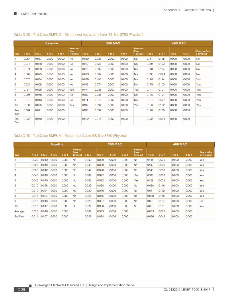
Appendix C Complete Test Data SMF8 Test Results
Table C-39 Test Case SMF8-3—Disconnect Active Link from IES-8 to 3750 (Physical)
Baseline 200 MAC 400 MAC
Run 7 to 8 8 to 7 4 to 5 5 to 4
Peer-to-Peer Timeout 7 to 8 8 to 7 4 to 5 5 to 4
Peer-to-Peer Timeout 7 to 8 8 to 7 4 to 5 5 to 4
Peer-to-Peer Timeout
1 0.067 0.087 0.000 0.000 No 0.080 0.085 0.000 0.000 No 0.111 0.118 0.000 0.000 No
2 0.075 0.078 0.000 0.000 No 0.087 0.122 0.000 0.000 No 0.096 0.109 0.000 0.000 No
3 0.074 0.058 0.000 0.000 No 0.081 0.092 0.000 0.000 No 0.084 0.104 0.000 0.000 No
4 0.067 0.075 0.000 0.000 No 0.093 0.092 0.000 0.000 No 0.080 0.094 0.000 0.000 No
5 0.070 0.064 0.000 0.000 No 0.089 0.116 0.000 0.000 No 0.118 0.144 0.000 0.000 Yes
6 0.024 0.068 0.000 0.000 No 0.102 0.074 0.000 0.000 No 0.175 0.100 0.000 0.000 Yes
7 0.157 0.095 0.000 0.000 Yes 0.144 0.086 0.000 0.000 Yes 0.141 0.101 0.000 0.000 Yes
8 0.096 0.048 0.000 0.000 No 0.109 0.086 0.000 0.000 No 0.175 0.104 0.000 0.000 Yes
9 0.078 0.043 0.000 0.000 No 0.111 0.072 0.000 0.000 No 0.131 0.092 0.000 0.000 Yes
10 0.130 0.095 0.000 0.000 Yes 0.137 0.094 0.000 0.000 Yes 0.166 0.122 0.000 0.000 Yes
Average
0.084 0.071 0.000 0.000 0.103 0.092 0.000 0.000 0.128 0.109 0.000 0.000
Std Dev.
0.037 0.018 0.000 0.000 0.022 0.016 0.000 0.000 0.036 0.016 0.000 0.000
Table C-40 Test Case SMF8-4—Reconnect Cable IES-8 to 3750 (Physical)
Baseline 200 MAC 400 MAC
Run 7 to 8 8 to 7 4 to 5 5 to 4
Peer-to-Peer Timeout 7 to 8 8 to 7 4 to 5 5 to 4
Peer-to-Peer Timeout 7 to 8 8 to 7 4 to 5 5 to 4
Peer-to-Peer Timeout
1 0.029 0.010 0.000 0.000 No 0.050 0.020 0.000 0.000 No 0.141 0.030 0.000 0.000 Yes
2 0.027 0.010 0.000 0.000 No 0.045 0.020 0.000 0.000 No 0.149 0.030 0.000 0.000 Yes
3 0.036 0.012 0.000 0.000 No 0.047 0.020 0.000 0.000 No 0.145 0.030 0.000 0.000 Yes
4 0.040 0.010 0.000 0.000 No 0.088 0.022 0.000 0.000 Yes 0.108 0.033 0.000 0.000 Yes
5 0.045 0.010 0.000 0.000 No 0.083 0.022 0.000 0.000 Yes 0.129 0.033 0.000 0.000 Yes
6 0.010 0.028 0.000 0.000 No 0.023 0.068 0.000 0.000 No 0.030 0.116 0.000 0.000 Yes
7 0.010 0.024 0.000 0.000 No 0.020 0.070 0.000 0.000 No 0.031 0.129 0.000 0.000 Yes
8 0.013 0.024 0.000 0.000 No 0.020 0.065 0.000 0.000 No 0.030 0.118 0.000 0.000 Yes
9 0.010 0.016 0.000 0.000 No 0.020 0.057 0.000 0.000 No 0.031 0.127 0.000 0.000 No
10 0.010 0.017 0.000 0.000 No 0.024 0.068 0.000 0.000 No 0.031 0.131 0.000 0.000 Yes
Average 0.023 0.016 0.000 0.000 0.042 0.043 0.000 0.000 0.083 0.078 0.000 0.000
Std Dev. 0.014 0.007 0.000 0.000 0.026 0.024 0.000 0.000 0.056 0.049 0.000 0.000
C-26Converged Plantwide Ethernet (CPwE) Design and Implementation Guide
OL-21226-01, ENET-TD001E-EN-P
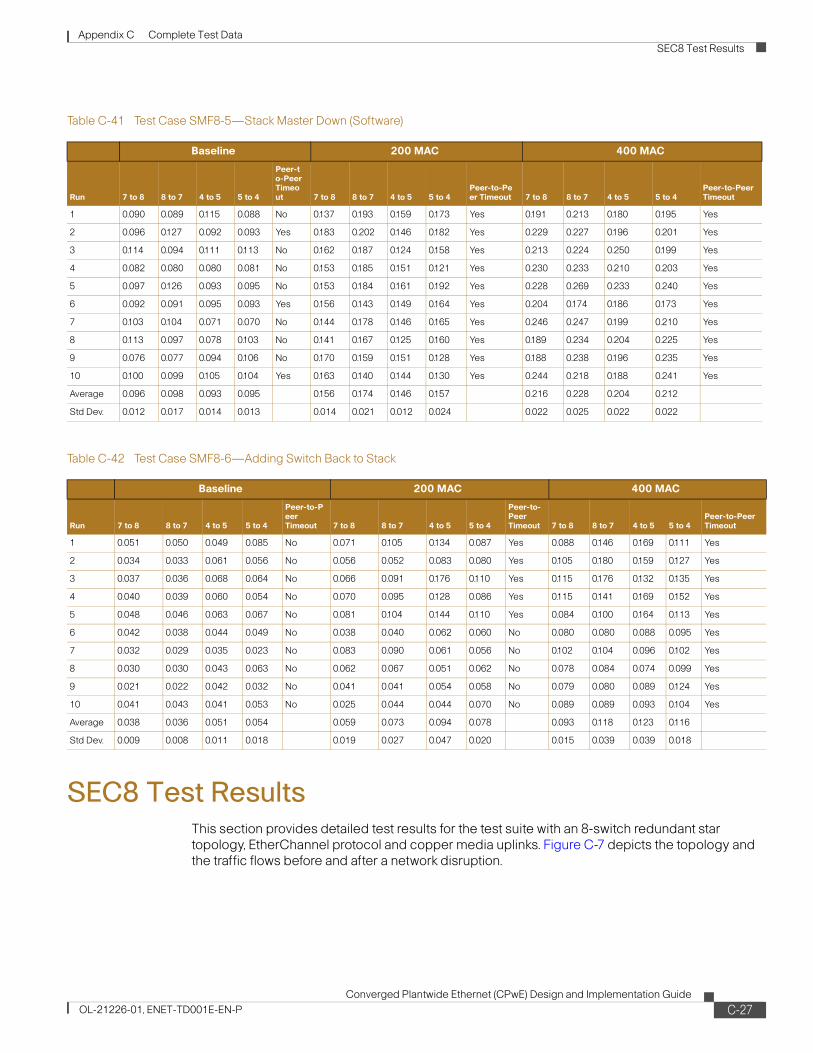
Appendix C Complete Test Data SEC8 Test Results
SEC8 Test ResultsThis section provides detailed test results for the test suite with an 8-switch redundant star topology, EtherChannel protocol and copper media uplinks. Figure C-7 depicts the topology and the traffic flows before and after a network disruption.
Table C-41 Test Case SMF8-5—Stack Master Down (Software)
Baseline 200 MAC 400 MAC
Run 7 to 8 8 to 7 4 to 5 5 to 4
Peer-to-Peer Timeout 7 to 8 8 to 7 4 to 5 5 to 4
Peer-to-Peer Timeout 7 to 8 8 to 7 4 to 5 5 to 4
Peer-to-Peer Timeout
1 0.090 0.089 0.115 0.088 No 0.137 0.193 0.159 0.173 Yes 0.191 0.213 0.180 0.195 Yes
2 0.096 0.127 0.092 0.093 Yes 0.183 0.202 0.146 0.182 Yes 0.229 0.227 0.196 0.201 Yes
3 0.114 0.094 0.111 0.113 No 0.162 0.187 0.124 0.158 Yes 0.213 0.224 0.250 0.199 Yes
4 0.082 0.080 0.080 0.081 No 0.153 0.185 0.151 0.121 Yes 0.230 0.233 0.210 0.203 Yes
5 0.097 0.126 0.093 0.095 No 0.153 0.184 0.161 0.192 Yes 0.228 0.269 0.233 0.240 Yes
6 0.092 0.091 0.095 0.093 Yes 0.156 0.143 0.149 0.164 Yes 0.204 0.174 0.186 0.173 Yes
7 0.103 0.104 0.071 0.070 No 0.144 0.178 0.146 0.165 Yes 0.246 0.247 0.199 0.210 Yes
8 0.113 0.097 0.078 0.103 No 0.141 0.167 0.125 0.160 Yes 0.189 0.234 0.204 0.225 Yes
9 0.076 0.077 0.094 0.106 No 0.170 0.159 0.151 0.128 Yes 0.188 0.238 0.196 0.235 Yes
10 0.100 0.099 0.105 0.104 Yes 0.163 0.140 0.144 0.130 Yes 0.244 0.218 0.188 0.241 Yes
Average 0.096 0.098 0.093 0.095 0.156 0.174 0.146 0.157 0.216 0.228 0.204 0.212
Std Dev. 0.012 0.017 0.014 0.013 0.014 0.021 0.012 0.024 0.022 0.025 0.022 0.022
Table C-42 Test Case SMF8-6—Adding Switch Back to Stack
Baseline 200 MAC 400 MAC
Run 7 to 8 8 to 7 4 to 5 5 to 4
Peer-to-Peer Timeout 7 to 8 8 to 7 4 to 5 5 to 4
Peer-to-Peer Timeout 7 to 8 8 to 7 4 to 5 5 to 4
Peer-to-Peer Timeout
1 0.051 0.050 0.049 0.085 No 0.071 0.105 0.134 0.087 Yes 0.088 0.146 0.169 0.111 Yes
2 0.034 0.033 0.061 0.056 No 0.056 0.052 0.083 0.080 Yes 0.105 0.180 0.159 0.127 Yes
3 0.037 0.036 0.068 0.064 No 0.066 0.091 0.176 0.110 Yes 0.115 0.176 0.132 0.135 Yes
4 0.040 0.039 0.060 0.054 No 0.070 0.095 0.128 0.086 Yes 0.115 0.141 0.169 0.152 Yes
5 0.048 0.046 0.063 0.067 No 0.081 0.104 0.144 0.110 Yes 0.084 0.100 0.164 0.113 Yes
6 0.042 0.038 0.044 0.049 No 0.038 0.040 0.062 0.060 No 0.080 0.080 0.088 0.095 Yes
7 0.032 0.029 0.035 0.023 No 0.083 0.090 0.061 0.056 No 0.102 0.104 0.096 0.102 Yes
8 0.030 0.030 0.043 0.063 No 0.062 0.067 0.051 0.062 No 0.078 0.084 0.074 0.099 Yes
9 0.021 0.022 0.042 0.032 No 0.041 0.041 0.054 0.058 No 0.079 0.080 0.089 0.124 Yes
10 0.041 0.043 0.041 0.053 No 0.025 0.044 0.044 0.070 No 0.089 0.089 0.093 0.104 Yes
Average 0.038 0.036 0.051 0.054 0.059 0.073 0.094 0.078 0.093 0.118 0.123 0.116
Std Dev. 0.009 0.008 0.011 0.018 0.019 0.027 0.047 0.020 0.015 0.039 0.039 0.018
C-27Converged Plantwide Ethernet (CPwE) Design and Implementation Guide
OL-21226-01, ENET-TD001E-EN-P

Appendix C Complete Test Data SEC8 Test Results
Figure C-7 SEC8—Bring Down Active Link Between IES-8 and 3750
Table C-43 Test Case SEC8-1—Shutdown Link IES-8 to 3750
Baseline 200 MAC, 80 Mcast Groups 400 MAC, 200 Mcast Groups
Run7 to 8 Ucast
8 to 7 Ucast
7 to 8 Mcast
8 to 7 Mcast
I/O Timeout
7 to 8 Ucast
8 to 7 Ucast
7 to 8 Mcast
8 to 7 Mcast
I/O Timeout
7 to 8 Ucast
8 to 7 Ucast
7 to 8 Mcast
8 to 7 Mcast
I/O Timeout
1 0.393 0.001 0.393 0.001 Yes 0.425 0.001 0.818 0.001 Yes 0.407 0.001 0.799 0.001 Yes
2 0.798 0.001 0.798 0.001 Yes 0.216 0.001 0.416 0.001 Yes 0.417 0.001 0.817 0.001 Yes
3 0.780 0.001 0.780 0.001 Yes 0.207 0.001 0.398 0.001 Yes 0.203 0.001 0.397 0.001 Yes
4 0.815 0.001 0.815 0.001 Yes 0.421 0.001 0.810 0.001 Yes 0.210 0.001 0.450 0.039 Yes
5 0.413 0.001 0.413 0.001 Yes 0.417 0.001 0.802 0.001 Yes 0.398 0.001 0.780 0.001 Yes
6 0.001 0.374 0.001 0.374 Yes 0.001 0.402 0.001 0.803 Yes 0.001 0.202 0.002 0.403 Yes
7 0.001 0.788 0.001 0.788 Yes 0.001 0.394 0.001 0.789 Yes 0.001 0.188 0.001 0.376 Yes
8 0.001 0.781 0.001 0.781 Yes 0.001 0.389 0.001 0.779 Yes 0.001 0.194 0.001 0.388 Yes
9 0.001 0.782 0.001 0.783 Yes 0.001 0.192 0.002 0.385 Yes 0.001 0.192 0.001 0.383 Yes
10 0.001 0.396 0.002 0.396 Yes 0.001 0.389 0.001 0.778 Yes 0.001 0.203 0.002 0.406 Yes
Average 0.321 0.313 0.321 0.313 0.169 0.177 0.325 0.354 0.164 0.098 0.325 0.200
Std Dev. 0.366 0.359 0.366 0.359 0.193 0.195 0.372 0.391 0.187 0.103 0.368 0.202
VLAN 1710.17.10.x
Link Disruption
After
Before
.10
.11
.12
.13
.17
.16
Fa1/1 Ixia 3/2
.15
.14
IES-7IES-2
CZ-3750
IES-3
IES-4 IES-5
IES-6
2278
48
E
E E
E
E E
E E
8
7
4 5
Fa1/2
Fa1/3
Ixia 3/1
Ixia 3/3
Fa1/2
Ixia 3/4
IES-1IXIA
IXIA
IES-8
C-28Converged Plantwide Ethernet (CPwE) Design and Implementation Guide
OL-21226-01, ENET-TD001E-EN-P

Appendix C Complete Test Data SEC8 Test Results
Table C-44 Test Case SEC8-2—Bring Up Link IES-8 to 3750
Baseline 200 MAC, 80 Mcast Groups 400 MAC, 200 Mcast Groups
Run7 to 8 Ucast
8 to 7 Ucast
7 to 8 Mcast
8 to 7 Mcast
I/O Timeout
7 to 8 Ucast
8 to 7 Ucast
7 to 8 Mcast
8 to 7 Mcast
I/O Timeout
7 to 8 Ucast
8 to 7 Ucast
7 to 8 Mcast
8 to 7 Mcast
I/O Timeout
1 0.000 0.011 0.007 0.011 No 0.000 0.011 0.009 0.005 No 0.000 0.012 0.014 0.006 No
2 0.000 0.012 0.006 0.012 No 0.000 0.010 0.005 0.005 No 0.000 0.011 0.012 0.006 No
3 0.000 0.011 0.006 0.011 No 0.000 0.011 0.009 0.005 No 0.000 0.010 0.012 0.005 No
4 0.000 0.010 0.007 0.010 No 0.000 0.012 0.008 0.006 No 0.000 0.012 0.011 0.006 No
5 0.000 0.011 0.007 0.011 No 0.000 0.011 0.223 0.219 No 0.000 0.010 0.011 0.005 No
6 0.031 0.023 0.031 0.028 No 0.016 0.014 0.033 0.036 No 0.017 0.015 0.034 0.040 No
7 0.024 0.021 0.024 0.026 No 0.015 0.012 0.030 0.032 No 0.015 0.013 0.030 0.036 No
8 0.028 0.023 0.028 0.029 No 0.013 0.010 0.025 0.029 No 0.017 0.014 0.034 0.039 No
9 0.032 0.025 0.032 0.031 No 0.013 0.010 0.027 0.028 No 0.016 0.015 0.033 0.040 No
10 0.024 0.018 0.024 0.024 No 0.013 0.011 0.027 0.029 Yes 0.015 0.012 0.029 0.035 No
Average 0.014 0.016 0.017 0.019 0.007 0.011 0.039 0.039 0.008 0.012 0.022 0.022
Std Dev. 0.015 0.006 0.011 0.009 0.007 0.001 0.065 0.064 0.008 0.002 0.011 0.017
Table C-45 Test Case SEC8-3—Disconnect IES-8 from 3750 (Physical)
Baseline 200 MAC, 80 Mcast Groups 400 MAC, 200 Mcast Groups
Run7 to 8 Ucast
8 to 7 Ucast
7 to 8 Mcast
8 to 7 Mcast
I/O Timeout
7 to 8 Ucast
8 to 7 Ucast
7 to 8 Mcast
8 to 7 Mcast
I/O Timeout
7 to 8 Ucast
8 to 7 Ucast
7 to 8 Mcast
8 to 7 Mcast
I/O Timeout
1 0.397 0.772 0.397 0.772 Yes 0.198 0.767 0.381 0.384 Yes 0.197 0.791 0.387 0.411 Yes
2 0.773 0.382 0.773 0.382 Yes 0.194 0.770 0.373 0.385 Yes 0.205 0.790 0.401 0.411 Yes
3 0.788 0.389 0.788 0.389 Yes 0.208 0.787 0.399 0.394 Yes 0.203 0.753 0.399 0.391 Yes
4 0.393 0.775 0.393 0.775 Yes 0.404 0.361 0.777 0.181 Yes 0.196 0.774 0.385 0.403 Yes
5 0.376 0.767 0.376 0.767 Yes 0.405 0.387 0.778 0.193 Yes 0.200 0.774 0.392 0.403 Yes
6 0.378 0.789 0.378 0.789 Yes 0.397 0.196 0.794 0.393 Yes 0.180 0.398 0.361 0.796 Yes
7 0.795 0.397 0.795 0.397 Yes 0.382 0.197 0.764 0.394 Yes 0.190 0.398 0.379 0.795 Yes
8 0.370 0.766 0.370 0.766 Yes 0.189 0.398 0.377 0.795 Yes 0.396 0.196 0.791 0.392 Yes
9 0.377 0.778 0.377 0.778 Yes 0.379 0.184 0.758 0.369 Yes 0.186 0.385 0.373 0.771 Yes
10 0.374 0.781 0.374 0.781 Yes 0.180 0.387 0.359 0.773 Yes 0.182 0.395 0.364 0.789 Yes
Average 0.502 0.659 0.502 0.659 0.294 0.443 0.576 0.426 0.213 0.565 0.423 0.556
Std Dev. 0.196 0.187 0.196 0.187 0.106 0.244 0.209 0.206 0.065 0.230 0.130 0.199
C-29Converged Plantwide Ethernet (CPwE) Design and Implementation Guide
OL-21226-01, ENET-TD001E-EN-P

Appendix C Complete Test Data SEC8 Test Results
Table C-46 Test Case SEC8-4—Reconnect Cable IES-8 to 3750 (Physical)
Baseline 200 MAC, 80 Mcast Groups 400 MAC, 200 Mcast Groups
Run7 to 8 Ucast
8 to 7 Ucast
7 to 8 Mcast
8 to 7 Mcast
I/O Timeout
7 to 8 Ucast
8 to 7 Ucast
7 to 8 Mcast
8 to 7 Mcast
I/O Timeout
7 to 8 Ucast
8 to 7 Ucast
7 to 8 Mcast
8 to 7 Mcast
I/O Timeout
1 0.000 0.011 0.021 0.025 No 0.000 0.010 0.010 0.005 No 0.000 0.010 0.012 0.005 No
2 0.000 0.010 0.021 0.011 No 0.000 0.011 0.009 0.006 No 0.000 0.011 0.012 0.006 No
3 0.000 0.012 0.006 0.012 No 0.000 0.010 0.009 0.005 No 0.000 0.010 0.012 0.005 No
4 0.000 0.011 0.007 0.011 No 0.000 0.012 0.008 0.006 No 0.000 0.010 0.031 0.026 No
5 0.000 0.011 0.006 0.011 No 0.000 0.011 0.008 0.005 No 0.000 0.011 0.012 0.006 No
6 0.022 0.019 0.022 0.029 No 0.014 0.011 0.028 0.030 No 0.017 0.015 0.034 0.040 No
7 0.023 0.018 0.023 0.025 No 0.014 0.011 0.029 0.030 No 0.015 0.013 0.031 0.040 No
8 0.028 0.024 0.028 0.030 No 0.015 0.011 0.030 0.030 No 0.018 0.015 0.036 0.043 Yes
9 0.027 0.022 0.027 0.028 No 0.014 0.011 0.028 0.030 No 0.016 0.013 0.031 0.036 No
10 0.026 0.022 0.026 0.028 No 0.012 0.011 0.024 0.030 No 0.015 0.011 0.029 0.036 No
Average 0.013 0.016 0.019 0.021 0.007 0.011 0.018 0.018 0.008 0.012 0.024 0.024
Std Dev. 0.013 0.005 0.009 0.008 0.007 0.001 0.010 0.013 0.009 0.002 0.010 0.017
Table C-47 Test Case SEC8-5—Stack Master Down (Software)
Baseline 200 MAC, 80 Mcast Groups 400 MAC, 200 Mcast Groups
Run7 to 8 Ucast
8 to 7 Ucast
7 to 8 Mcast
8 to 7 Mcast
I/O Timeout
7 to 8 Ucast
8 to 7 Ucast
7 to 8 Mcast
8 to 7 Mcast
I/O Timeout
7 to 8 Ucast
8 to 7 Ucast
7 to 8 Mcast
8 to 7 Mcast
I/O Timeout
1 0.371 1.209 0.371 1.209 Yes 0.628 0.579 1.208 0.192 Yes 0.664 0.637 1.303 0.176 Yes
2 1.189 0.000 1.189 0.000 Yes 0.778 0.996 0.186 1.214 Yes 0.826 0.802 0.201 1.218 Yes
3 0.774 1.190 0.774 1.190 Yes 0.631 0.581 1.212 0.385 Yes 0.605 0.580 1.187 0.177 Yes
4 1.211 0.000 1.211 0.000 Yes 0.985 0.799 0.392 1.202 Yes 0.774 0.801 0.192 1.193 Yes
5 0.398 1.235 0.398 1.235 Yes 0.623 0.574 1.197 0.394 Yes 0.616 0.590 1.207 0.369 Yes
6 0.000 0.000 0.000 0.000 Yes 0.609 0.610 0.000 0.000 Yes 0.610 0.611 0.000 0.000 Yes
7 1.217 1.220 1.217 1.220 Yes 1.123 1.125 2.247 2.249 Yes 0.609 0.611 1.219 1.221 Yes
8 0.000 0.000 0.000 0.000 Yes 0.605 0.606 0.000 0.000 Yes 0.598 0.599 0.000 0.000 Yes
9 1.213 1.216 1.213 1.216 Yes 1.007 1.009 2.014 2.017 Yes 0.609 0.610 1.218 1.220 Yes
10 0.000 0.000 0.000 0.000 Yes 0.606 0.608 0.000 0.000 Yes 0.598 0.599 0.000 0.000 Yes
Average 0.637 0.607 0.637 0.607 0.760 0.749 0.846 0.765 0.651 0.644 0.653 0.557
Std Dev. 0.544 0.640 0.544 0.640 0.202 0.216 0.850 0.852 0.082 0.084 0.610 0.575
C-30Converged Plantwide Ethernet (CPwE) Design and Implementation Guide
OL-21226-01, ENET-TD001E-EN-P

Appendix C Complete Test Data SEF8 Test Results
SEF8 Test ResultsThis section provides detailed test results for the test suite with an 8-switch redundant star topology, EtherChannel protocol and fiber media uplinks. Figure C-8 depicts the topology and the traffic flows before and after a network disruption.
Figure C-8 SEF8—Bring Down Active Link Between IES-8 and 3750
Table C-48 Test Case SEC8-6—Bring Switch Back to Stack
Baseline 200 MAC, 80 Mcast Groups 400 MAC, 200 Mcast Groups
Run7 to 8 Ucast
8 to 7 Ucast
7 to 8 Mcast
8 to 7 Mcast
I/O Timeout
7 to 8 Ucast
8 to 7 Ucast
7 to 8 Mcast
8 to 7 Mcast
I/O Timeout
7 to 8 Ucast
8 to 7 Ucast
7 to 8 Mcast
8 to 7 Mcast
I/O Timeout
1 0.032 0.023 92.389 0.023 Yes 0.025 0.031 94.292 0.012 Yes 0.048 0.035 16.123 0.012 Yes
2 0.000 0.015 0.000 9.593 Yes 0.010 0.010 24.101 26.257 Yes 0.012 0.009 22.976 26.995 Yes
3 0.034 0.026 1.879 0.026 Yes 0.027 0.036 26.390 0.014 Yes 0.045 0.049 0.151 0.018 Yes
4 0.000 0.022 0.000 22.760 Yes 0.006 0.008 7.149 25.003 Yes 0.007 0.007 10.503 50.456 Yes
5 0.037 0.024 27.488 0.024 Yes 0.030 0.030 35.356 0.011 Yes 0.025 0.028 13.683 0.011 Yes
6 0.000 0.000 0.000 0.000 Yes 0.023 0.023 0.442 0.443 Yes 0.031 0.032 0.000 0.000 Yes
7 0.074 0.059 0.077 0.063 Yes 0.057 0.018 4.479 4.383 Yes 0.027 0.027 3.506 3.505 Yes
8 0.000 0.000 0.000 0.000 Yes 0.052 0.048 0.000 0.000 Yes 0.021 0.019 0.000 0.000 Yes
9 1.094 1.086 21.923 21.913 Yes 0.396 0.317 0.791 0.642 Yes 0.343 0.046 29.111 28.536 Yes
10 0.000 0.000 0.000 0.000 Yes 0.045 0.043 0.000 0.000 Yes 0.048 0.036 0.000 0.000 Yes
Average 0.127 0.125 14.376 5.440 0.067 0.056 19.300 5.677 0.061 0.029 9.605 10.953
Std Dev. 0.341 0.338 29.267 9.394 0.117 0.093 29.374 10.605 0.100 0.014 10.659 17.955
VLAN 1710.17.10.x
Link Disruption
After
Before
.10
.11
.12
.13
.17
.16
Fa1/1 Ixia 3/2
.15
.14
IES-7IES-2
CZ-3750
IES-3
IES-4 IES-5
IES-6
2278
48E
E E
E
E E
E E
8
7
4 5
Fa1/2
Fa1/3
Ixia 3/1
Ixia 3/3
Fa1/2
Ixia 3/4
IES-1IXIA
IXIA
IES-8
C-31Converged Plantwide Ethernet (CPwE) Design and Implementation Guide
OL-21226-01, ENET-TD001E-EN-P

Appendix C Complete Test Data SEF8 Test Results
Table C-49 Test Case SEF8-1—Bring Down Link IES-8 to 3750 (Software)
Baseline 200 MAC, 80 Mcast Groups 400 MAC, 200 Mcast Groups
Run7 to 8 Ucast
8 to 7 Ucast
7 to 8 Mcast
8 to 7 Mcast
I/O Timeout
7 to 8 Ucast
8 to 7 Ucast
7 to 8 Mcast
8 to 7 Mcast
I/O Timeout
7 to 8 Ucast
8 to 7 Ucast
7 to 8 Mcast
8 to 7 Mcast
I/O Timeout
1 0.097 0.000 0.097 0.000 No 0.047 0.000 0.090 0.001 No 0.032 0.000 0.063 0.001 No
2 0.078 0.030 0.078 0.030 No 0.051 0.000 0.098 0.001 No 0.030 0.000 0.060 0.001 No
3 0.080 0.000 0.080 0.000 No 0.032 0.000 0.062 0.001 No 0.048 0.000 0.094 0.001 No
4 0.078 0.000 0.078 0.000 No 0.036 0.000 0.069 0.001 No 0.049 0.000 0.096 0.001 No
5 0.077 0.000 0.077 0.000 No 0.039 0.000 0.076 0.001 No 0.047 0.000 0.093 0.001 No
6 0.001 0.071 0.001 0.071 No 0.001 0.045 0.001 0.089 No 0.001 0.039 0.001 0.079 No
7 0.001 0.076 0.001 0.076 No 0.001 0.042 0.002 0.084 No 0.001 0.039 0.001 0.077 No
8 0.001 0.073 0.001 0.073 No 0.001 0.028 0.001 0.056 No 0.001 0.027 0.001 0.054 No
9 0.001 0.059 0.002 0.059 No 0.001 0.030 0.001 0.059 No 0.001 0.029 0.001 0.058 No
10 0.001 0.066 0.001 0.066 No 0.001 0.040 0.001 0.080 No 0.001 0.037 0.001 0.075 No
Average 0.042 0.037 0.042 0.037 0.021 0.018 0.040 0.037 0.021 0.017 0.041 0.035
Std Dev. 0.043 0.035 0.043 0.035 0.022 0.020 0.042 0.040 0.022 0.018 0.044 0.036
Table C-50 Test Case SEF8-2—Bring Up Link IES-8 to 3750 (Software)
Baseline 200 MAC, 80 Mcast Groups 400 MAC, 200 Mcast Groups
Run7 to 8 Ucast
8 to 7 Ucast
7 to 8 Mcast
8 to 7 Mcast
I/O Timeout
7 to 8 Ucast
8 to 7 Ucast
7 to 8 Mcast
8 to 7 Mcast
I/O Timeout
7 to 8 Ucast
8 to 7 Ucast
7 to 8 Mcast
8 to 7 Mcast
I/O Timeout
1 0.007 0.000 0.000 0.000 No 0.000 0.000 0.009 0.005 No 0.000 0.000 0.012 0.005 No
2 0.000 0.000 0.000 0.000 No 0.000 0.000 0.011 0.005 No 0.000 0.000 0.010 0.005 No
3 0.000 0.000 0.009 0.000 No 0.000 0.000 0.009 0.005 No 0.000 0.000 0.012 0.005 No
4 0.000 0.000 0.008 0.000 No 0.000 0.000 0.011 0.005 No 0.000 0.000 0.014 0.005 No
5 0.000 0.000 0.008 0.000 No 0.000 0.000 0.009 0.005 No 0.000 0.000 0.012 0.005 No
6 0.021 0.016 0.021 0.021 No 0.011 0.009 0.023 0.025 No 0.013 0.012 0.026 0.033 No
7 0.024 0.018 0.024 0.024 No 0.011 0.009 0.022 0.025 No 0.013 0.011 0.025 0.031 No
8 0.025 0.018 0.025 0.023 No 0.012 0.010 0.024 0.026 No 0.013 0.012 0.026 0.034 No
9 0.020 0.018 0.020 0.023 No 0.011 0.010 0.022 0.027 No 0.015 0.012 0.030 0.035 No
10 0.020 0.016 0.020 0.021 No 0.011 0.010 0.022 0.027 No 0.013 0.011 0.027 0.032 No
Average 0.012 0.009 0.014 0.011 0.006 0.005 0.016 0.015 0.007 0.006 0.019 0.019
Std Dev. 0.011 0.009 0.010 0.012 0.006 0.005 0.007 0.011 0.007 0.006 0.008 0.015
Table C-51 Test Case SEF8-3—Disconnect IES-8 from 3750 (Physical)
Baseline 200 MAC, 80 Mcast Groups 400 MAC, 200 Mcast Groups
Run7 to 8 Ucast
8 to 7 Ucast
7 to 8 Mcast
8 to 7 Mcast
I/O Timeout
7 to 8 Ucast
8 to 7 Ucast
7 to 8 Mcast
8 to 7 Mcast
I/O Timeout
7 to 8 Ucast
8 to 7 Ucast
7 to 8 Mcast
8 to 7 Mcast
I/O Timeout
1 0.062 0.000 0.062 0.000 0.000 0.037 0.000 0.070 0.033 0.000 0.047 0.000 0.092 0.037 0.000
2 0.089 0.000 0.089 0.000 0.000 0.038 0.000 0.072 0.031 0.000 0.040 0.000 0.078 0.022 0.000
3 0.057 0.000 0.057 0.000 0.000 0.044 0.000 0.084 0.025 0.000 0.047 0.000 0.093 0.023 0.000
4 0.068 0.000 0.068 0.000 0.000 0.037 0.000 0.071 0.039 0.000 0.026 0.000 0.050 0.028 0.000
5 0.066 0.000 0.066 0.000 0.000 0.047 0.000 0.090 0.039 0.000 0.038 0.000 0.075 0.029 0.000
6 0.074 0.038 0.074 0.038 No 0.045 0.024 0.090 0.048 No 0.042 0.007 0.083 0.014 No
C-32Converged Plantwide Ethernet (CPwE) Design and Implementation Guide
OL-21226-01, ENET-TD001E-EN-P

Appendix C Complete Test Data SEF8 Test Results
7 0.132 0.042 0.132 0.041 No 0.041 0.020 0.081 0.039 No 0.050 0.008 0.100 0.016 No
8 0.078 0.057 0.077 0.057 No 0.063 0.005 0.126 0.009 No 0.043 0.025 0.086 0.050 No
9 0.102 0.032 0.102 0.032 No 0.060 0.006 0.119 0.011 No 0.062 0.011 0.125 0.023 No
10 0.074 0.040 0.073 0.040 No 0.033 0.020 0.065 0.040 No 0.047 0.028 0.092 0.055 No
Average 0.080 0.021 0.080 0.021 0.044 0.007 0.087 0.031 0.044 0.008 0.087 0.030
Std Dev. 0.022 0.023 0.023 0.023 0.010 0.010 0.021 0.013 0.009 0.010 0.019 0.014
Table C-52 Test Case SEF8-4—Reconnect Cable IES-8 to 3750 (Physical)
Baseline 200 MAC, 80 Mcast Groups 400 MAC, 200 Mcast Groups
Run7 to 8 Ucast
8 to 7 Ucast
7 to 8 Mcast
8 to 7 Mcast
I/O Timeout
7 to 8 Ucast
8 to 7 Ucast
7 to 8 Mcast
8 to 7 Mcast
I/O Timeout
7 to 8 Ucast
8 to 7 Ucast
7 to 8 Mcast
8 to 7 Mcast
I/O Timeout
1 0.000 0.000 0.008 0.000 No 0.000 0.000 0.008 0.006 No 0.000 0.000 0.013 0.005 No
2 0.000 0.000 0.006 0.000 No 0.000 0.000 0.008 0.005 No 0.000 0.000 0.009 0.005 No
3 0.000 0.000 0.008 0.000 No 0.000 0.000 0.011 0.005 No 0.000 0.000 0.011 0.005 No
4 0.000 0.000 0.009 0.000 No 0.000 0.000 0.009 0.005 No 0.000 0.000 0.012 0.005 No
5 0.000 0.000 0.008 0.000 No 0.000 0.000 0.011 0.005 No 0.000 0.000 0.012 0.005 No
6 0.018 0.016 0.018 0.021 No 0.013 0.010 0.025 0.026 No 0.013 0.011 0.027 0.034 No
7 0.020 0.017 0.020 0.023 No 0.011 0.009 0.021 0.025 No 0.014 0.012 0.029 0.034 No
8 0.023 0.018 0.023 0.023 No 0.011 0.009 0.022 0.025 No 0.013 0.011 0.027 0.032 No
9 0.023 0.016 0.022 0.021 No 0.011 0.009 0.022 0.026 No 0.013 0.011 0.025 0.031 No
10 0.022 0.017 0.022 0.022 No 0.012 0.010 0.024 0.028 No 0.014 0.011 0.028 0.032 No
Average 0.011 0.008 0.014 0.011 0.006 0.005 0.016 0.016 0.007 0.006 0.019 0.019
Std Dev. 0.011 0.009 0.007 0.012 0.006 0.005 0.007 0.011 0.007 0.006 0.008 0.015
Table C-53 Test Case SEF8-5—Stack Master Down (Software)
Baseline 200 MAC, 80 Mcast Groups 400 MAC, 200 Mcast Groups
Run7 to 8 Ucast
8 to 7 Ucast
7 to 8 Mcast
8 to 7 Mcast
I/O Timeout
7 to 8 Ucast
8 to 7 Ucast
7 to 8 Mcast
8 to 7 Mcast
I/O Timeout
7 to 8 Ucast
8 to 7 Ucast
7 to 8 Mcast
8 to 7 Mcast
I/O Timeout
1 1.232 0.000 1.232 0.000 Yes 0.599 0.645 0.017 1.210 Yes 0.632 0.640 0.028 1.232 Yes
2 0.037 1.226 0.037 1.226 Yes 0.618 0.569 1.188 0.021 Yes 0.637 0.611 2.115 0.881 Yes
3 1.201 0.000 1.201 0.000 Yes 0.627 0.668 0.030 1.240 Yes 0.617 0.638 0.027 1.204 Yes
4 0.024 1.204 0.024 1.204 Yes 0.631 0.581 1.212 0.021 Yes 0.629 0.603 1.232 0.027 Yes
5 1.218 0.000 1.218 0.000 Yes 0.590 0.637 0.019 1.187 Yes 0.626 0.632 0.028 1.218 Yes
6 0.000 0.000 0.000 0.000 Yes 0.614 0.615 0.000 0.000 Yes 0.588 0.589 0.000 0.000 Yes
7 1.193 1.196 1.193 1.196 Yes 0.610 0.611 1.219 1.222 Yes 0.599 0.600 1.197 1.200 Yes
8 0.000 0.000 0.000 0.000 Yes 0.612 0.613 0.000 0.000 Yes 0.610 0.667 0.000 0.000 Yes
9 1.178 1.181 1.179 1.181 0.609 0.610 1.217 1.220 0.614 0.615 1.227 1.229
10 0.000 0.000 0.000 0.000 0.592 0.593 0.000 0.000 0.592 0.593 0.000 0.000
Average 0.608 0.481 0.608 0.481 8.152 0.610 0.614 0.490 0.612 20.172 0.614 0.619 0.585 0.699 8.632
Std Dev. 0.629 0.621 0.629 0.621 0.259 0.014 0.030 0.619 0.636 37.881 0.017 0.025 0.782 0.605 0.629
Table C-51 Test Case SEF8-3—Disconnect IES-8 from 3750 (Physical) (continued)
Baseline 200 MAC, 80 Mcast Groups 400 MAC, 200 Mcast Groups
Run7 to 8 Ucast
8 to 7 Ucast
7 to 8 Mcast
8 to 7 Mcast
I/O Timeout
7 to 8 Ucast
8 to 7 Ucast
7 to 8 Mcast
8 to 7 Mcast
I/O Timeout
7 to 8 Ucast
8 to 7 Ucast
7 to 8 Mcast
8 to 7 Mcast
I/O Timeout
C-33Converged Plantwide Ethernet (CPwE) Design and Implementation Guide
OL-21226-01, ENET-TD001E-EN-P
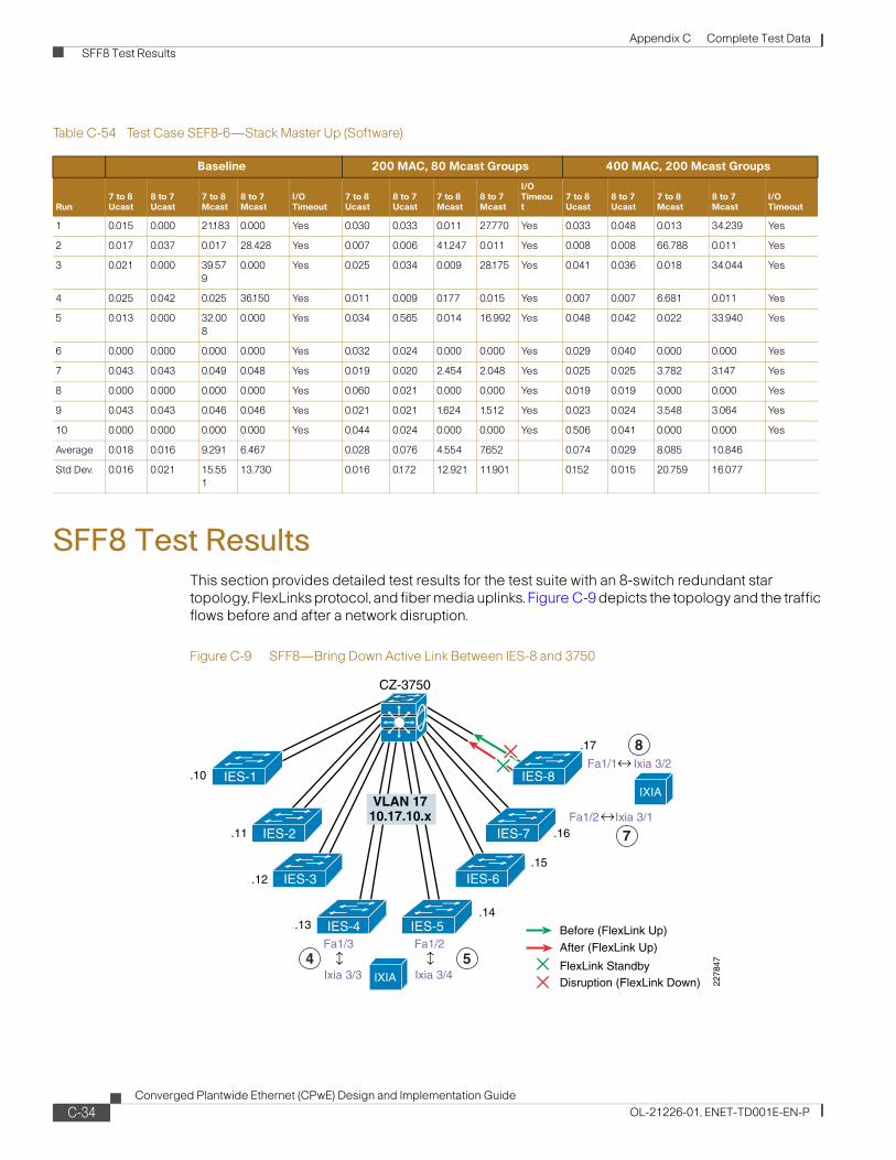
Appendix C Complete Test Data SFF8 Test Results
SFF8 Test ResultsThis section provides detailed test results for the test suite with an 8-switch redundant star topology, FlexLinks protocol, and fiber media uplinks. Figure C-9 depicts the topology and the traffic flows before and after a network disruption.
Figure C-9 SFF8—Bring Down Active Link Between IES-8 and 3750
Table C-54 Test Case SEF8-6—Stack Master Up (Software)
Baseline 200 MAC, 80 Mcast Groups 400 MAC, 200 Mcast Groups
Run7 to 8 Ucast
8 to 7 Ucast
7 to 8 Mcast
8 to 7 Mcast
I/O Timeout
7 to 8 Ucast
8 to 7 Ucast
7 to 8 Mcast
8 to 7 Mcast
I/O Timeout
7 to 8 Ucast
8 to 7 Ucast
7 to 8 Mcast
8 to 7 Mcast
I/O Timeout
1 0.015 0.000 21.183 0.000 Yes 0.030 0.033 0.011 27.770 Yes 0.033 0.048 0.013 34.239 Yes
2 0.017 0.037 0.017 28.428 Yes 0.007 0.006 41.247 0.011 Yes 0.008 0.008 66.788 0.011 Yes
3 0.021 0.000 39.579
0.000 Yes 0.025 0.034 0.009 28.175 Yes 0.041 0.036 0.018 34.044 Yes
4 0.025 0.042 0.025 36.150 Yes 0.011 0.009 0.177 0.015 Yes 0.007 0.007 6.681 0.011 Yes
5 0.013 0.000 32.008
0.000 Yes 0.034 0.565 0.014 16.992 Yes 0.048 0.042 0.022 33.940 Yes
6 0.000 0.000 0.000 0.000 Yes 0.032 0.024 0.000 0.000 Yes 0.029 0.040 0.000 0.000 Yes
7 0.043 0.043 0.049 0.048 Yes 0.019 0.020 2.454 2.048 Yes 0.025 0.025 3.782 3.147 Yes
8 0.000 0.000 0.000 0.000 Yes 0.060 0.021 0.000 0.000 Yes 0.019 0.019 0.000 0.000 Yes
9 0.043 0.043 0.046 0.046 Yes 0.021 0.021 1.624 1.512 Yes 0.023 0.024 3.548 3.064 Yes
10 0.000 0.000 0.000 0.000 Yes 0.044 0.024 0.000 0.000 Yes 0.506 0.041 0.000 0.000 Yes
Average 0.018 0.016 9.291 6.467 0.028 0.076 4.554 7.652 0.074 0.029 8.085 10.846
Std Dev. 0.016 0.021 15.551
13.730 0.016 0.172 12.921 11.901 0.152 0.015 20.759 16.077
VLAN 1710.17.10.x
FlexLink StandbyDisruption (FlexLink Down)
After (FlexLink Up)
Before (FlexLink Up)
.10
.11
.12
.13
.17
.16
Fa1/1 Ixia 3/2
.15
.14
IES-7IES-2
CZ-3750
IES-3
IES-4 IES-5
IES-6
2278
47
8
7
4 5
Fa1/2
Fa1/3
Ixia 3/1
Ixia 3/3
Fa1/2
Ixia 3/4
IES-1 IES-8IXIA
IXIA
C-34Converged Plantwide Ethernet (CPwE) Design and Implementation Guide
OL-21226-01, ENET-TD001E-EN-P

Appendix C Complete Test Data SFF8 Test Results
Table C-55 Test Case SFF8-1—Shutdown Link Between IES-8 and 3750 (Software)
Baseline 200 MAC, 80 Mcast Groups 400 MAC, 200 Mcast Groups
RunUcast 8 to 7
Ucast 7 to 8
Mcast 8 to 7
Mcast 7 to 8
I/O Timeout
Ucast 8 to 7
Ucast 7 to 8
Mcast 8 to 7
Mcast 7 to 8
I/O Timeout
Ucast 8 to 7
Ucast 7 to 8
Mcast 8 to 7
Mcast 7 to 8 I/O Timeout
1 0.030 0.021 0.021 0.021 No 0.033 0.014 0.014 0.014 No 0.049 0.012 0.012 0.012 No
2 0.059 0.027 0.027 0.027 No 0.026 0.016 0.016 0.016 No 0.033 0.016 0.016 0.016 No
3 0.017 0.005 0.005 0.005 No 0.037 0.021 0.020 0.020 No 0.038 0.010 0.010 0.010 No
4 0.068 0.045 0.045 0.045 No 0.026 0.016 0.016 0.016 No 0.042 0.017 0.017 0.017 No
5 0.057 0.029 0.029 0.029 No 0.054 0.032 0.032 0.032 No 0.065 0.027 0.027 0.027 No
6 0.021 0.017 0.017 0.017 No 0.029 0.012 0.012 0.012 No 0.023 0.005 0.005 0.005 No
7 0.021 0.035 0.021 0.021 No 0.021 0.038 0.021 0.021 No 0.019 0.053 0.019 0.019 No
8 0.011 0.043 0.011 0.011 No 0.027 0.038 0.027 0.027 No 0.016 0.033 0.016 0.016 No
9 0.009 0.026 0.009 0.009 No 0.040 0.057 0.040 0.041 No 0.016 0.045 0.016 0.016 No
10 0.016 0.051 0.016 0.016 No 0.031 0.041 0.031 0.031 No 0.033 0.057 0.033 0.033 No
11 0.006 0.034 0.006 0.006 No 0.027 0.044 0.027 0.027 No 0.010 0.044 0.010 0.010 No
12 0.027 0.041 0.027 0.027 No 0.013 0.023 0.013 0.013 No 0.014 0.033 0.014 0.014 No
Average 0.028 0.031 0.019 0.019 0.000 0.030 0.029 0.022 0.023 0.030 0.029 0.016 0.016
Std Dev. 0.021 0.013 0.012 0.012 0.000 0.010 0.014 0.009 0.009 0.017 0.018 0.008 0.008
Table C-56 Test Case SFF8-2—Bring Up Link IES-8 to 3750 (Software)
Baseline 200 MAC, 80 Mcast Groups 400 MAC, 200 Mcast Groups
RunUcast 8 to 7
Ucast 7 to 8
Mcast 8 to 7
Mcast 7 to 8
Peer-to-Peer Timeout
Ucast 8 to 7
Ucast 7 to 8
Mcast 8 to 7
Mcast 7 to 8
I/O Timeout
Ucast 8 to 7
Ucast 7 to 8
Mcast 8 to 7
Mcast 7 to 8
I/O Timeout
1 0.000 0.000 0.000 0.000 No 0.000 0.000 0.000 0.000 No 0.000 0.000 0.000 0.000 No
2 0.000 0.000 0.000 0.000 No 0.000 0.000 0.000 0.000 No 0.000 0.000 0.000 0.000 No
3 0.000 0.000 0.000 0.000 No 0.000 0.000 0.000 0.000 No 0.000 0.000 0.000 0.000 No
4 0.000 0.000 0.000 0.000 No 0.000 0.000 0.000 0.000 No 0.000 0.000 0.000 0.000 No
5 0.000 0.000 0.000 0.000 No 0.000 0.000 0.000 0.000 No 0.000 0.000 0.000 0.000 No
6 0.000 0.000 0.000 0.000 No 0.000 0.000 0.000 0.000 No 0.000 0.000 0.000 0.000 No
7 0.000 0.000 0.000 0.000 No 0.000 0.000 0.000 0.000 No 0.000 0.000 0.000 0.000 No
8 0.000 0.000 0.000 0.000 No 0.000 0.000 0.000 0.000 No 0.000 0.000 0.000 0.000 No
9 0.000 0.000 0.000 0.000 No 0.000 0.000 0.000 0.000 No 0.000 0.000 0.000 0.000 No
10 0.000 0.000 0.000 0.000 No 0.000 0.000 0.000 0.000 No 0.000 0.000 0.000 0.000 No
11 0.000 0.000 0.000 0.000 No 0.000 0.000 0.000 0.000 No 0.000 0.000 0.000 0.000 No
12 0.000 0.000 0.000 0.000 No 0.000 0.000 0.000 0.000 No 0.000 0.000 0.000 0.000 No
Average 0.000 0.000 0.000 0.000 0.000 0.000 0.000 0.000 0.000 0.000 0.000 0.000
Std Dev. 0.000 0.000 0.000 0.000 0.000 0.000 0.000 0.000 0.000 0.000 0.000 0.000
C-35Converged Plantwide Ethernet (CPwE) Design and Implementation Guide
OL-21226-01, ENET-TD001E-EN-P
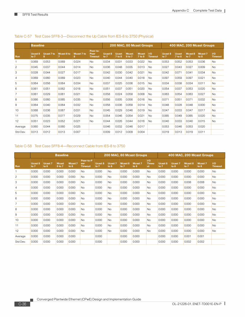
Appendix C Complete Test Data SFF8 Test Results
Table C-57 Test Case SFF8-3—Disconnect the Up Cable from IES-8 to 3750 (Physical)
Baseline 200 MAC, 80 Mcast Groups 400 MAC, 200 Mcast Groups
RunUcast 8 to 7
Ucast 7 to 8
Mcast 8 to 7
Mcast 7 to 8
Peer-to-Peer Timeout
Ucast 8 to 7
Ucast 7 to 8
Mcast 8 to 7
Mcast 7 to 8
I/O Timeout
Ucast 8 to 7
Ucast 7 to 8
Mcast 8 to 7
Mcast 7 to 8
I/O Timeout
1 0.069 0.053 0.069 0.024 No 0.034 0.031 0.033 0.022 No 0.053 0.052 0.053 0.036 No
2 0.045 0.037 0.044 0.014 No 0.036 0.048 0.035 0.013 No 0.027 0.043 0.027 0.009 No
3 0.028 0.044 0.027 0.017 No 0.042 0.030 0.042 0.021 No 0.042 0.071 0.041 0.034 No
4 0.069 0.060 0.069 0.023 No 0.040 0.044 0.040 0.018 No 0.097 0.059 0.097 0.021 No
5 0.064 0.056 0.064 0.034 No 0.037 0.025 0.036 0.015 No 0.034 0.038 0.034 0.011 No
6 0.061 0.051 0.062 0.018 No 0.051 0.037 0.051 0.020 No 0.054 0.037 0.053 0.020 No
7 0.061 0.029 0.061 0.021 No 0.058 0.024 0.058 0.008 No 0.063 0.054 0.063 0.027 No
8 0.066 0.060 0.065 0.035 No 0.056 0.005 0.056 0.016 No 0.071 0.051 0.071 0.032 No
9 0.064 0.040 0.064 0.032 No 0.058 0.036 0.058 0.014 No 0.048 0.028 0.048 0.000 No
10 0.068 0.036 0.067 0.031 No 0.045 0.029 0.046 0.019 No 0.047 0.033 0.047 0.017 No
11 0.075 0.035 0.077 0.029 No 0.054 0.046 0.054 0.021 No 0.065 0.049 0.065 0.020 No
12 0.051 0.023 0.052 0.021 No 0.044 0.026 0.044 0.016 No 0.040 0.033 0.040 0.015 No
Average 0.060 0.044 0.060 0.025 0.046 0.032 0.046 0.017 0.053 0.046 0.053 0.020
Std Dev. 0.013 0.012 0.013 0.007 0.009 0.012 0.009 0.004 0.019 0.013 0.019 0.011
Table C-58 Test Case SFF8-4—Reconnect Cable from IES-8 to 3750
Baseline 200 MAC, 80 Mcast Groups 400 MAC, 200 Mcast Groups
RunUcast 8 to 7
Ucast 7 to 8
Mcast 8 to 7
Mcast 7 to 8
Peer-to-Peer Timeout
Ucast 8 to 7
Ucast 7 to 8
Mcast 8 to 7
Mcast 7 to 8
I/O Timeout
Ucast 8 to 7
Ucast 7 to 8
Mcast 8 to 7
Mcast 7 to 8
I/O Timeout
1 0.000 0.000 0.000 0.000 No 0.000 No 0.000 0.000 No 0.000 0.000 0.000 0.000 No
2 0.000 0.000 0.000 0.000 No 0.000 No 0.000 0.000 No 0.000 0.000 0.000 0.000 No
3 0.000 0.000 0.000 0.000 No 0.000 No 0.000 0.000 No 0.000 0.000 0.008 0.008 No
4 0.000 0.000 0.000 0.000 No 0.000 No 0.000 0.000 No 0.000 0.000 0.000 0.000 No
5 0.000 0.000 0.000 0.000 No 0.000 No 0.000 0.000 No 0.000 0.000 0.000 0.000 No
6 0.000 0.000 0.000 0.000 No 0.000 No 0.000 0.000 No 0.000 0.000 0.000 0.000 No
7 0.000 0.000 0.000 0.000 No 0.000 No 0.000 0.000 No 0.000 0.000 0.000 0.000 No
8 0.000 0.000 0.000 0.000 No 0.000 No 0.000 0.000 No 0.000 0.000 0.000 0.000 No
9 0.000 0.000 0.000 0.000 No 0.000 No 0.000 0.000 No 0.000 0.000 0.000 0.000 No
10 0.000 0.000 0.000 0.000 No 0.000 No 0.000 0.000 No 0.000 0.000 0.000 0.000 No
11 0.000 0.000 0.000 0.000 No 0.000 No 0.000 0.000 No 0.000 0.000 0.000 0.000 No
12 0.000 0.000 0.000 0.000 No 0.000 No 0.000 0.000 No 0.000 0.000 0.000 0.000 No
Average 0.000 0.000 0.000 0.000 0.000 0.000 0.000 0.000 0.000 0.001 0.001
Std Dev. 0.000 0.000 0.000 0.000 0.000 0.000 0.000 0.000 0.000 0.002 0.002
C-36Converged Plantwide Ethernet (CPwE) Design and Implementation Guide
OL-21226-01, ENET-TD001E-EN-P

Appendix C Complete Test Data SFC8 Test Results
SFC8 Test ResultsThis section provides detailed test results for the test suite with an 8-switch redundant star topology, FlexLinks protocol, and copper media uplinks. Figure C-10 depicts the topology and the traffic flows before and after a network disruption.
Table C-59 Test Case SFF8-5—Stack Master Down (Software)
Baseline 200 MAC, 80 Mcast Groups 400 MAC, 200 Mcast Groups
RunUcast 8 to 7
Ucast 7 to 8
Mcast 8 to 7
Mcast 7 to 8
Peer-to-Peer Timeout
Ucast 8 to 7
Ucast 7 to 8
Mcast 8 to 7
Mcast 7 to 8
I/O Tiimeout
Ucast 8 to 7
Ucast 7 to 8
Mcast 8 to 7
Mcast 7 to 8
I/O Timeout
1 0.056 0.058 0.031 0.031 No 0.072 0.061 0.061 0.061 No 0.060 0.052 0.019 0.019 No
2 0.030 0.057 0.030 0.030 No 0.061 0.067 0.034 0.034 No 0.090 0.072 0.027 0.027 Yes1
1. Stack Master Down (100MAC). Test unveiled problems with safety controller (O) dropping out.
3 0.049 0.051 0.023 0.023 No 0.025 0.039 0.021 0.021 No 0.087 0.103 0.040 0.040 Yes
4 0.055 0.059 0.037 0.037 No 0.064 0.054 0.034 0.034 No 0.082 0.065 0.025 0.025 Yes1
5 0.065 0.064 0.037 0.037 No 0.033 0.053 0.033 Yes 0.000 0.061 0.079 0.034 0.034 No
6 0.053 0.054 0.036 0.036 No 0.038 0.065 0.038 Yes 0.000 0.075 0.088 0.028 0.028 No
7 0.051 0.055 0.040 0.040 Yes 0.055 0.070 0.040 Yes 0.000 0.084 0.078 0.030 0.030 No
8 0.063 0.031 0.031 0.031 No 0.073 0.039 0.039 Yes 0.000 0.084 0.085 0.027 0.027 No
9 0.055 0.086 0.055 0.055 No 0.072 0.060 0.039 Yes 0.000 0.087 0.055 0.026 0.026 No
10 0.027 0.060 0.027 0.027 No 0.058 0.070 0.049 Yes 0.000 0.088 0.060 0.033 0.033 No
11 0.049 0.047 0.036 0.036 No 0.040 0.058 0.040 Yes 0.000 0.050 0.075 0.024 0.024 Yes
12 0.044 0.047 0.040 0.040 No 0.029 0.049 0.020 Yes 0.000 0.072 0.067 0.024 0.024 No
Average 0.050 0.056 0.035 0.035 0.052 0.057 0.037 0.000 0.077 0.073 0.028 0.028
Std Dev. 0.011 0.013 0.008 0.008 0.018 0.011 0.011 0.000 0.013 0.015 0.006 0.006
Table C-60 Test Case SFF8-6—Return Switch to Stack (Physical)
Baseline 200 MAC, 80 Mcast Groups 400 MAC, 200 Mcast Groups
RunUcast 8 to 7
Ucast 7 to 8
Mcast 8 to 7
Mcast 7 to 8
Peer-to-Peer Timeout
Ucast 8 to 7
Ucast 7 to 8
Mcast 8 to 7
Mcast 7 to 8
I/O Timeout
Ucast 8 to 7
Ucast 7 to 8
Mcast 8 to 7
Mcast 7 to 8
I/O Timeout
1 0.000 0.000 0.000 0.000 No 0.000 0.000 0.000 0.000 No 0.000 0.000 0.000 0.000 No
2 0.000 0.000 0.000 0.000 No 0.000 0.000 0.000 0.000 No 0.000 0.000 0.000 0.000 No
3 0.000 0.000 0.000 0.000 No 0.000 0.000 0.000 0.000 No 0.000 0.000 0.000 0.000 No
4 0.000 0.000 0.000 0.000 No 0.000 0.000 0.000 0.000 No 0.000 0.000 3.609 3.608 No
5 0.000 0.000 0.000 0.000 No 0.000 0.000 0.000 0.000 No 0.000 0.000 0.000 0.000 No
6 0.000 0.000 0.000 0.000 No 0.000 0.000 0.000 0.000 No 0.000 0.000 8.618 8.619 No
7 0.000 0.000 0.000 0.000 No 0.000 0.000 0.000 0.000 No 0.000 0.000 0.000 0.000 No
8 0.000 0.000 0.000 0.000 No 0.000 0.000 0.000 0.000 No 0.000 0.000 0.000 0.000 No
9 0.000 0.000 0.000 0.000 No 0.000 0.000 0.000 0.000 No 0.000 0.000 0.000 0.000 No
10 0.000 0.000 0.000 0.000 No 0.000 0.000 0.000 0.000 No 0.000 0.000 0.000 0.000 No
11 0.000 0.000 0.000 0.000 No 0.000 0.000 0.000 0.000 No 0.000 0.000 0.000 0.000 No
12 0.000 0.000 0.000 0.000 No 0.000 0.000 0.000 0.000 No 0.000 0.000 0.000 0.000 No
Average 0.000 0.000 0.000 0.000 0.000 0.000 0.000 0.000 0.000 0.000 1.019 1.019
Std Dev. 0.000 0.000 0.000 0.000 0.000 0.000 0.000 0.000 0.000 0.000 2.608 2.608
C-37Converged Plantwide Ethernet (CPwE) Design and Implementation Guide
OL-21226-01, ENET-TD001E-EN-P

Appendix C Complete Test Data SFC8 Test Results
Figure C-10 SFC8—Bring Down Active Link Between IES-8 and 3750
Table C-61 Test Case SFC8-1—Shutdown Link Between IES-8 and 3750 (Software)
Baseline 200 MAC, 80 Mcast Groups 400 MAC, 200 Mcast Groups
Run7 to 8 Ucast
8 to 7 Ucast
7 to 8 Mcast
8 to 7 Mcast
I/O Timeout
7 to 8 Ucast
8 to 7 Ucast
7 to 8 Mcast
8 to 7 Mcast
I/O Timeout
7 to 8 Ucast
8 to 7 Ucast
7 to 8 Mcast
8 to 7 Mcast
I/O Timeout
1 0.045 0.027 0.027 0.027 No 0.067 0.042 0.042 0.042 No 0.140 0.018 0.018 0.018 No
2 0.056 0.025 0.025 0.025 No 0.028 0.018 0.018 0.018 No 0.030 0.015 0.015 0.015 No
3 0.017 0.010 0.010 0.010 No 0.045 0.028 0.028 0.028 No 0.054 0.017 0.017 0.017 No
4 0.040 0.011 0.011 0.011 No 0.016 0.005 0.005 0.005 No 0.047 0.029 0.029 0.029 No
5 0.024 0.005 0.005 0.005 No 0.109 0.012 0.012 0.012 No 0.048 0.007 0.007 0.007 No
6 0.011 0.008 0.008 0.008 No 0.030 0.021 0.021 0.021 No 0.036 0.017 0.018 0.018 No
7 0.015 0.030 0.015 0.015 No 0.006 0.018 0.006 0.006 No 0.008 0.033 0.008 0.008 No
8 0.044 0.073 0.044 0.044 No 0.012 0.043 0.012 0.012 No 0.017 0.075 0.017 0.017 No
9 0.011 0.033 0.011 0.011 No 0.023 0.037 0.023 0.023 No 0.029 0.052 0.029 0.029 No
10 0.019 0.046 0.019 0.019 No 0.024 0.048 0.024 0.024 No 0.017 0.061 0.017 0.017 No
11 0.021 0.025 0.021 0.021 No 0.032 0.044 0.032 0.032 No 0.028 0.052 0.028 0.028 No
12 0.029 0.048 0.029 0.029 No 0.028 0.179 0.028 0.028 No 0.013 0.074 0.013 0.013 No
Average 0.028 0.028 0.019 0.019 0.035 0.041 0.021 0.021 0.039 0.038 0.018 0.018
Std Dev. 0.015 0.020 0.011 0.011 0.028 0.046 0.011 0.011 0.035 0.024 0.007 0.007
Table C-62 Test Case SFC8-2—Bring Up Link IES-8 to 3750 (Software)
Baseline 200 MAC, 80 Mcast Groups 400 MAC, 200 Mcast Groups
Run7 to 8 Ucast
8 to 7 Ucast
7 to 8 Mcast
8 to 7 Mcast
I/O Timeout
7 to 8 Ucast
8 to 7 Ucast
7 to 8 Mcast
8 to 7 Mcast
I/O Timeout
7 to 8 Ucast
8 to 7 Ucast
7 to 8 Mcast
8 to 7 Mcast
I/O Timeout
1 0.000 0.000 0.000 0.000 No 0.000 0.000 0.000 0.000 No 0.000 0.000 0.196 0.196 No
2 0.000 0.000 0.000 0.000 No 0.000 0.000 0.000 0.000 No 0.000 0.000 0.000 0.000 No
3 0.000 0.000 0.000 0.000 No 0.000 0.000 0.000 0.000 No 0.000 0.000 0.000 0.000 No
4 0.000 0.000 0.000 0.000 No 0.000 0.000 0.000 0.000 No 0.000 0.000 0.000 0.000 No
5 0.000 0.000 0.000 0.000 No 0.000 0.000 0.000 0.000 No 0.000 0.000 0.083 0.071 No
VLAN 1710.17.10.x
FlexLink StandbyDisruption (FlexLink Down)
After (FlexLink Up)
Before (FlexLink Up)
.10
.11
.12
.13
.17
.16
Fa1/1 Ixia 3/2
.15
.14
IES-7IES-2
CZ-3750
IES-3
IES-4 IES-5
IES-6
2278
47
8
7
4 5
Fa1/2
Fa1/3
Ixia 3/1
Ixia 3/3
Fa1/2
Ixia 3/4
IES-1 IES-8IXIA
IXIA
C-38Converged Plantwide Ethernet (CPwE) Design and Implementation Guide
OL-21226-01, ENET-TD001E-EN-P

Appendix C Complete Test Data SFC8 Test Results
6 0.000 0.000 0.000 0.000 No 0.000 0.000 0.000 0.000 No 0.000 0.000 3.042 3.042 No
7 0.000 0.000 0.000 0.000 No 0.000 0.000 0.000 0.000 No 0.000 0.000 0.000 0.000 No
8 0.000 0.000 0.000 0.000 No 0.000 0.000 0.000 0.000 No 0.000 0.000 0.000 0.000 No
9 0.000 0.000 0.000 0.000 No 0.000 0.000 0.000 0.000 No 0.000 0.000 0.000 0.000 No
10 0.000 0.000 0.000 0.000 No 0.000 0.000 0.000 0.000 No 0.000 0.000 0.000 0.000 No
11 0.000 0.000 0.000 0.000 No 0.000 0.000 0.000 0.000 No 0.000 0.000 0.000 0.000 No
12 0.000 0.000 0.000 0.000 No 0.000 0.000 0.000 0.000 No 0.000 0.000 0.000 0.000 No
Average 0.000 0.000 0.000 0.000 0.000 0.000 0.000 0.000 0.000 0.000 0.277 0.276
Std Dev. 0.000 0.000 0.000 0.000 0.000 0.000 0.000 0.000 0.000 0.000 0.873 0.873
Table C-63 Test Case SFC8-3—Disconnect IES-8 from 3750 (Physical)
Baseline 200 MAC, 80 Mcast Groups 400 MAC, 200 Mcast Groups
Run7 to 8 Ucast
8 to 7 Ucast
7 to 8 Mcast
8 to 7 Mcast
I/O Timeout
7 to 8 Ucast
8 to 7 Ucast
7 to 8 Mcast
8 to 7 Mcast
I/O Timeout
7 to 8 Ucast
8 to 7 Ucast
7 to 8 Mcast
8 to 7 Mcast
I/O Timeout
1 0.392 0.360 0.360 0.360 Yes 0.375 0.357 0.357 0.357 Yes 0.387 0.349 0.349 0.349 Yes
2 0.767 0.767 0.767 0.767 Yes 0.757 0.757 0.757 0.757 Yes 0.387 0.369 0.369 0.369 Yes
3 0.762 0.762 0.762 0.762 Yes 0.425 0.362 0.362 0.362 Yes 0.757 0.757 0.757 0.757 Yes
4 0.756 0.756 0.756 0.756 Yes 0.369 0.360 0.360 0.360 Yes 0.373 0.349 0.349 0.349 Yes
5 0.755 0.756 0.755 0.755 Yes 0.749 0.749 0.749 0.749 Yes 0.402 0.362 0.362 0.362 Yes
6 0.749 0.749 0.749 0.749 Yes 0.759 0.759 0.759 0.759 Yes 0.372 0.352 0.352 0.352 Yes
7 0.357 0.386 0.357 0.357 Yes 0.358 0.371 0.358 0.358 Yes 0.751 0.751 0.751 0.751 Yes
8 0.350 0.357 0.350 0.350 Yes 0.762 0.762 0.762 0.762 Yes 0.355 0.404 0.355 0.355 Yes
9 0.355 0.378 0.355 0.356 Yes 0.367 0.377 0.367 0.367 Yes 0.767 0.767 0.767 0.767 Yes
10 0.351 0.369 0.351 0.351 Yes 0.758 0.758 0.758 0.758 Yes 0.749 0.749 0.749 0.749 Yes
11 0.366 0.366 0.366 0.366 Yes 0.751 0.751 0.751 0.751 Yes 0.753 0.753 0.753 0.753 Yes
12 0.770 0.770 0.770 0.770 Yes 0.367 0.395 0.368 0.368 Yes 0.748 0.748 0.748 0.748 Yes
Average 0.561 0.565 0.558 0.558 0.566 0.563 0.559 0.559 0.567 0.559 0.555 0.555
Std Dev. 0.208 0.204 0.211 0.211 0.199 0.202 0.206 0.206 0.196 0.204 0.208 0.208
Table C-64 Test Case SFC8-4—Reconnect Cable from IES-8 to 3750 (Physical)
Baseline 200 MAC, 80 Mcast Groups 400 MAC, 200 Mcast Groups
Run7 to 8 Ucast
8 to 7 Ucast
7 to 8 Mcast
8 to 7 Mcast
I/O Timeout
7 to 8 Ucast
8 to 7 Ucast
7 to 8 Mcast
8 to 7 Mcast
I/O Timeout
7 to 8 Ucast
8 to 7 Ucast
7 to 8 Mcast
8 to 7 Mcast
I/O Timeout
1 0.000 0.000 0.000 0.000 No 0.000 0.000 0.000 0.000 No 0.000 0.000 0.000 0.000 No
2 0.000 0.000 0.000 0.000 No 0.000 0.000 0.000 0.000 No 0.000 0.000 0.000 0.000 No
3 0.000 0.000 0.000 0.000 No 0.000 0.000 0.000 0.000 No 0.000 0.000 0.000 0.000 No
4 0.000 0.000 0.000 0.000 No 0.000 0.000 0.000 0.000 No 0.000 0.000 0.000 0.000 No
5 0.000 0.000 0.000 0.000 No 0.000 0.000 0.000 0.000 No 0.000 0.000 0.000 0.000 No
6 0.000 0.000 0.000 0.000 No 0.000 0.000 0.000 0.000 No 0.000 0.000 0.000 0.000 No
7 0.000 0.000 0.000 0.000 No 0.000 0.000 0.000 0.000 No 0.000 0.000 0.000 0.000 No
8 0.000 0.000 0.000 0.000 No 0.000 0.000 0.000 0.000 No 0.000 0.000 0.000 0.000 No
Table C-62 Test Case SFC8-2—Bring Up Link IES-8 to 3750 (Software)
Baseline 200 MAC, 80 Mcast Groups 400 MAC, 200 Mcast Groups
Run7 to 8 Ucast
8 to 7 Ucast
7 to 8 Mcast
8 to 7 Mcast
I/O Timeout
7 to 8 Ucast
8 to 7 Ucast
7 to 8 Mcast
8 to 7 Mcast
I/O Timeout
7 to 8 Ucast
8 to 7 Ucast
7 to 8 Mcast
8 to 7 Mcast
I/O Timeout
C-39Converged Plantwide Ethernet (CPwE) Design and Implementation Guide
OL-21226-01, ENET-TD001E-EN-P
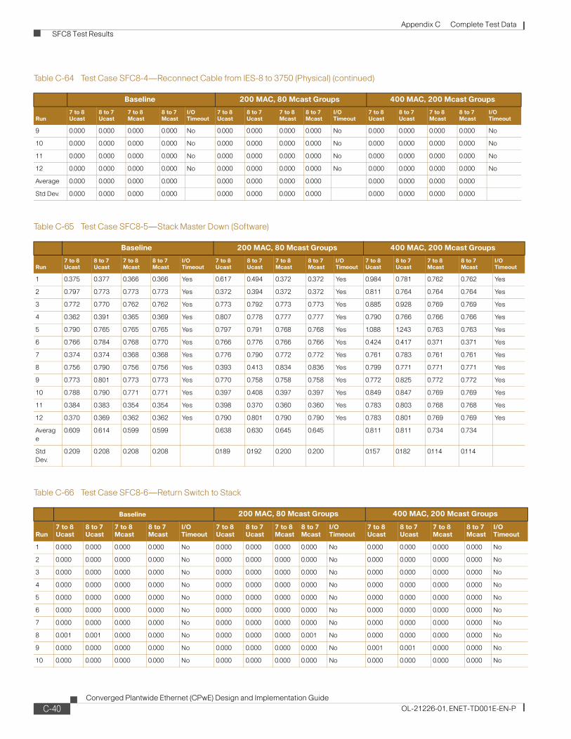
Appendix C Complete Test Data SFC8 Test Results
9 0.000 0.000 0.000 0.000 No 0.000 0.000 0.000 0.000 No 0.000 0.000 0.000 0.000 No
10 0.000 0.000 0.000 0.000 No 0.000 0.000 0.000 0.000 No 0.000 0.000 0.000 0.000 No
11 0.000 0.000 0.000 0.000 No 0.000 0.000 0.000 0.000 No 0.000 0.000 0.000 0.000 No
12 0.000 0.000 0.000 0.000 No 0.000 0.000 0.000 0.000 No 0.000 0.000 0.000 0.000 No
Average 0.000 0.000 0.000 0.000 0.000 0.000 0.000 0.000 0.000 0.000 0.000 0.000
Std Dev. 0.000 0.000 0.000 0.000 0.000 0.000 0.000 0.000 0.000 0.000 0.000 0.000
Table C-65 Test Case SFC8-5—Stack Master Down (Software)
Baseline 200 MAC, 80 Mcast Groups 400 MAC, 200 Mcast Groups
Run7 to 8 Ucast
8 to 7 Ucast
7 to 8 Mcast
8 to 7 Mcast
I/O Timeout
7 to 8 Ucast
8 to 7 Ucast
7 to 8 Mcast
8 to 7 Mcast
I/O Timeout
7 to 8 Ucast
8 to 7 Ucast
7 to 8 Mcast
8 to 7 Mcast
I/O Timeout
1 0.375 0.377 0.366 0.366 Yes 0.617 0.494 0.372 0.372 Yes 0.984 0.781 0.762 0.762 Yes
2 0.797 0.773 0.773 0.773 Yes 0.372 0.394 0.372 0.372 Yes 0.811 0.764 0.764 0.764 Yes
3 0.772 0.770 0.762 0.762 Yes 0.773 0.792 0.773 0.773 Yes 0.885 0.928 0.769 0.769 Yes
4 0.362 0.391 0.365 0.369 Yes 0.807 0.778 0.777 0.777 Yes 0.790 0.766 0.766 0.766 Yes
5 0.790 0.765 0.765 0.765 Yes 0.797 0.791 0.768 0.768 Yes 1.088 1.243 0.763 0.763 Yes
6 0.766 0.784 0.768 0.770 Yes 0.766 0.776 0.766 0.766 Yes 0.424 0.417 0.371 0.371 Yes
7 0.374 0.374 0.368 0.368 Yes 0.776 0.790 0.772 0.772 Yes 0.761 0.783 0.761 0.761 Yes
8 0.756 0.790 0.756 0.756 Yes 0.393 0.413 0.834 0.836 Yes 0.799 0.771 0.771 0.771 Yes
9 0.773 0.801 0.773 0.773 Yes 0.770 0.758 0.758 0.758 Yes 0.772 0.825 0.772 0.772 Yes
10 0.788 0.790 0.771 0.771 Yes 0.397 0.408 0.397 0.397 Yes 0.849 0.847 0.769 0.769 Yes
11 0.384 0.383 0.354 0.354 Yes 0.398 0.370 0.360 0.360 Yes 0.783 0.803 0.768 0.768 Yes
12 0.370 0.369 0.362 0.362 Yes 0.790 0.801 0.790 0.790 Yes 0.783 0.801 0.769 0.769 Yes
Average
0.609 0.614 0.599 0.599 0.638 0.630 0.645 0.645 0.811 0.811 0.734 0.734
Std Dev.
0.209 0.208 0.208 0.208 0.189 0.192 0.200 0.200 0.157 0.182 0.114 0.114
Table C-66 Test Case SFC8-6—Return Switch to Stack
Baseline 200 MAC, 80 Mcast Groups 400 MAC, 200 Mcast Groups
Run7 to 8 Ucast
8 to 7 Ucast
7 to 8 Mcast
8 to 7 Mcast
I/O Timeout
7 to 8 Ucast
8 to 7 Ucast
7 to 8 Mcast
8 to 7 Mcast
I/O Timeout
7 to 8 Ucast
8 to 7 Ucast
7 to 8 Mcast
8 to 7 Mcast
I/O Timeout
1 0.000 0.000 0.000 0.000 No 0.000 0.000 0.000 0.000 No 0.000 0.000 0.000 0.000 No
2 0.000 0.000 0.000 0.000 No 0.000 0.000 0.000 0.000 No 0.000 0.000 0.000 0.000 No
3 0.000 0.000 0.000 0.000 No 0.000 0.000 0.000 0.000 No 0.000 0.000 0.000 0.000 No
4 0.000 0.000 0.000 0.000 No 0.000 0.000 0.000 0.000 No 0.000 0.000 0.000 0.000 No
5 0.000 0.000 0.000 0.000 No 0.000 0.000 0.000 0.000 No 0.000 0.000 0.000 0.000 No
6 0.000 0.000 0.000 0.000 No 0.000 0.000 0.000 0.000 No 0.000 0.000 0.000 0.000 No
7 0.000 0.000 0.000 0.000 No 0.000 0.000 0.000 0.000 No 0.000 0.000 0.000 0.000 No
8 0.001 0.001 0.000 0.000 No 0.000 0.000 0.000 0.001 No 0.000 0.000 0.000 0.000 No
9 0.000 0.000 0.000 0.000 No 0.000 0.000 0.000 0.000 No 0.001 0.001 0.000 0.000 No
10 0.000 0.000 0.000 0.000 No 0.000 0.000 0.000 0.000 No 0.000 0.000 0.000 0.000 No
Table C-64 Test Case SFC8-4—Reconnect Cable from IES-8 to 3750 (Physical) (continued)
Baseline 200 MAC, 80 Mcast Groups 400 MAC, 200 Mcast Groups
Run7 to 8 Ucast
8 to 7 Ucast
7 to 8 Mcast
8 to 7 Mcast
I/O Timeout
7 to 8 Ucast
8 to 7 Ucast
7 to 8 Mcast
8 to 7 Mcast
I/O Timeout
7 to 8 Ucast
8 to 7 Ucast
7 to 8 Mcast
8 to 7 Mcast
I/O Timeout
C-40Converged Plantwide Ethernet (CPwE) Design and Implementation Guide
OL-21226-01, ENET-TD001E-EN-P

Appendix C Complete Test Data Application Latency (Screw-to-Screw) Test Results
Application Latency (Screw-to-Screw) Test ResultsAs described in Chapter 7, “Testing the CPwE Solution,” screw-to-screw tests were conducted to measure the application latency and jitter and identify the impact a path change has on the application latency and jitter. In Appendix B, “Test Result Analysis.” this data is summarized and used to estimate the latency added by additional switch hops. Figure C-11 to Figure C-23 show the test results from each screw-to-screw test iteration.
Figure C-11 Application Latency and Jitter in RMC 8, Short Path
11 0.001 0.001 0.000 0.000 No 0.000 0.000 0.000 0.000 No 0.000 0.000 0.000 0.000 No
12 0.001 0.001 0.001 0.001 No 0.001 0.001 0.000 0.000 No 0.000 0.001 0.000 0.000 No
Average
0.000 0.000 0.000 0.000 0.000 0.000 0.000 0.000 0.000 0.000 0.000 0.000
Std Dev.
0.000 0.000 0.000 0.000 0.000 0.000 0.000 0.000 0.000 0.000 0.000 0.000
Table C-66 Test Case SFC8-6—Return Switch to Stack (continued)
Baseline 200 MAC, 80 Mcast Groups 400 MAC, 200 Mcast Groups
Run7 to 8 Ucast
8 to 7 Ucast
7 to 8 Mcast
8 to 7 Mcast
I/O Timeout
7 to 8 Ucast
8 to 7 Ucast
7 to 8 Mcast
8 to 7 Mcast
I/O Timeout
7 to 8 Ucast
8 to 7 Ucast
7 to 8 Mcast
8 to 7 Mcast
I/O Timeout
C-41Converged Plantwide Ethernet (CPwE) Design and Implementation Guide
OL-21226-01, ENET-TD001E-EN-P

Appendix C Complete Test Data Application Latency (Screw-to-Screw) Test Results
Figure C-12 Application Latency and Jitter in RMC 8, Long Path
Figure C-13 Application Latency and Jitter in RMC16, Short Path
C-42Converged Plantwide Ethernet (CPwE) Design and Implementation Guide
OL-21226-01, ENET-TD001E-EN-P
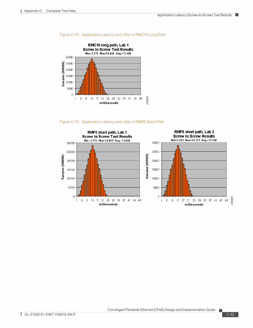
Appendix C Complete Test Data Application Latency (Screw-to-Screw) Test Results
Figure C-14 Application Latency and Jitter in RMC16, Long Path
Figure C-15 Application Latency and Jitter in RMF8, Short Path
C-43Converged Plantwide Ethernet (CPwE) Design and Implementation Guide
OL-21226-01, ENET-TD001E-EN-P

Appendix C Complete Test Data Application Latency (Screw-to-Screw) Test Results
Figure C-16 Application Latency and Jitter in RMF8, Long Path
Figure C-17 Application Latency and Jitter in SMC8, No Break
C-44Converged Plantwide Ethernet (CPwE) Design and Implementation Guide
OL-21226-01, ENET-TD001E-EN-P
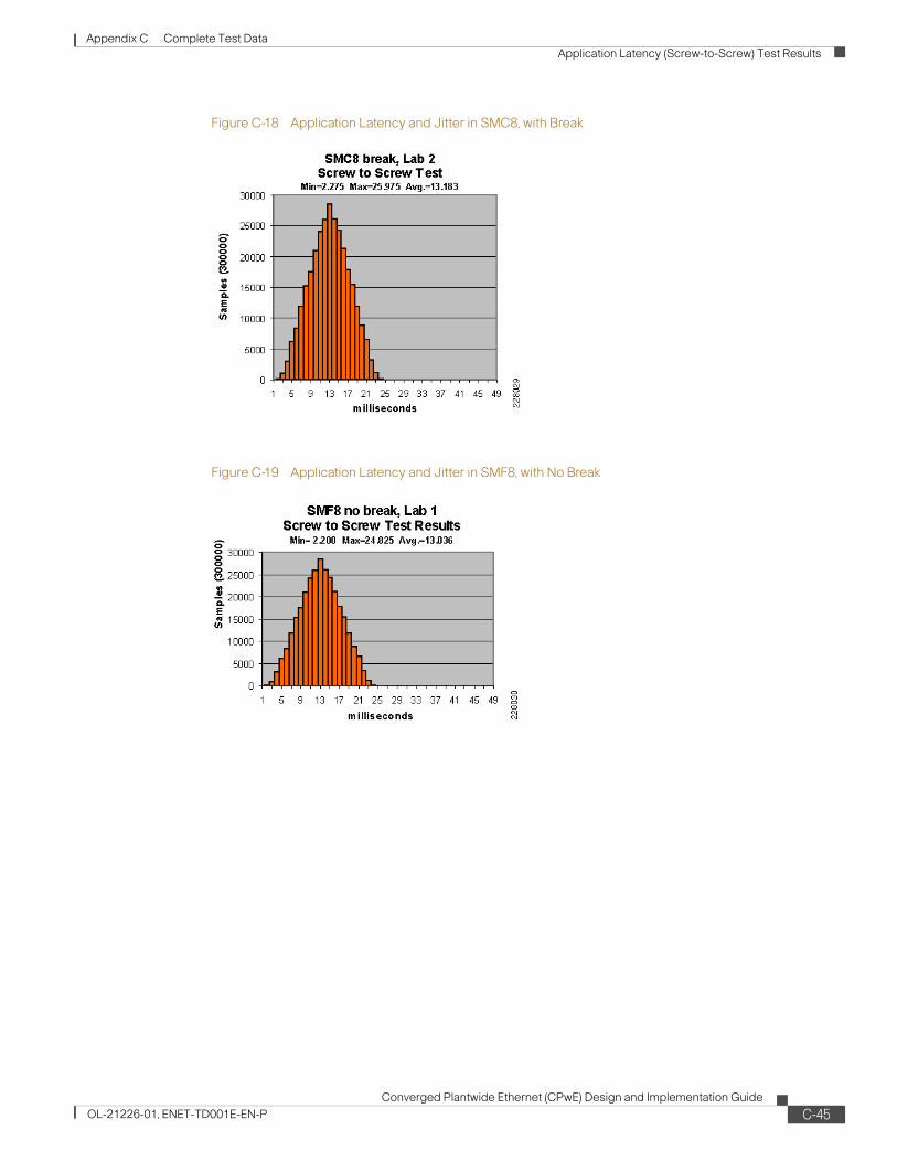
Appendix C Complete Test Data Application Latency (Screw-to-Screw) Test Results
Figure C-18 Application Latency and Jitter in SMC8, with Break
Figure C-19 Application Latency and Jitter in SMF8, with No Break
C-45Converged Plantwide Ethernet (CPwE) Design and Implementation Guide
OL-21226-01, ENET-TD001E-EN-P

Appendix C Complete Test Data Application Latency (Screw-to-Screw) Test Results
Figure C-20 Application Latency and Jitter in SEC8, with No Break
Figure C-21 Application Latency and Jitter in SEC8, with Break
C-46Converged Plantwide Ethernet (CPwE) Design and Implementation Guide
OL-21226-01, ENET-TD001E-EN-P

Appendix C Complete Test Data Application Latency (Screw-to-Screw) Test Results
Figure C-22 Application Latency and Jitter in SEF8, with No Break
Figure C-23 Application Latency and Jitter in SEF8, with Break
C-47Converged Plantwide Ethernet (CPwE) Design and Implementation Guide
OL-21226-01, ENET-TD001E-EN-P

Appendix C Complete Test Data Application Latency (Screw-to-Screw) Test Results
C-48Converged Plantwide Ethernet (CPwE) Design and Implementation Guide
OL-21226-01, ENET-TD001E-EN-P

Converged Plantwide Ethernet (CPwOL-21226-01, ENET-TD001E-EN-P
A P P E N D I X D
ConfigurationsExpress Setup
Stratix 8000The following is a sample of a Stratix 8000 configuration after running Express Setup. The Stratix 8000 was running Release 3 (IOS version 12.2(50)SE2).
version 12.2service nagleno service padservice tcp-keepalives-inservice tcp-keepalives-outservice timestamps debug datetime msec localtime show-timezoneservice timestamps log datetime msec localtime show-timezoneservice password-encryption!hostname Stratix8000!boot-start-markerboot-end-marker!logging buffered 16384no logging consoleenable secret level 1 5 $1$dIHm$S0Rzhzd9OWa9L5dgA5Egl.enable secret 5 $1$QIyE$FQLtO8wJiuyp.u3BYMi8n.!no aaa new-modelclock timezone EST -5clock summer-time EST recurringcip security password rockwellsystem mtu routing 1500ptp mode e2etransparent vtp mode transparentudld aggressive
ip subnet-zerono ip source-route!!no ip domain-lookup
D-1E) Design and Implementation Guide

Appendix D Configurations Express Setup
ip igmp snooping querier!mls qos map policed-dscp 24 27 31 43 46 47 55 59 to 0mls qos map dscp-cos 9 11 12 13 14 15 to 0mls qos map dscp-cos 25 26 28 29 30 to 2mls qos map dscp-cos 40 41 42 44 45 49 50 51 to 4mls qos map dscp-cos 52 53 54 56 57 58 60 61 to 4mls qos map dscp-cos 62 63 to 4mls qos map cos-dscp 0 8 16 27 32 47 55 59mls qos srr-queue input bandwidth 40 60mls qos srr-queue input threshold 1 16 66mls qos srr-queue input threshold 2 34 66mls qos srr-queue input buffers 40 60 mls qos srr-queue input cos-map queue 1 threshold 2 1mls qos srr-queue input cos-map queue 1 threshold 3 0 2mls qos srr-queue input cos-map queue 2 threshold 2 4mls qos srr-queue input cos-map queue 2 threshold 3 3 5 6 7mls qos srr-queue input dscp-map queue 1 threshold 2 8 10mls qos srr-queue input dscp-map queue 1 threshold 3 0 1 2 3 4 5 6 7mls qos srr-queue input dscp-map queue 1 threshold 3 9 11 12 13 14 15 16 17mls qos srr-queue input dscp-map queue 1 threshold 3 18 19 20 21 22 23 25 26mls qos srr-queue input dscp-map queue 1 threshold 3 28 29 30mls qos srr-queue input dscp-map queue 2 threshold 2 32 33 34 35 36 37 38 39mls qos srr-queue input dscp-map queue 2 threshold 2 40 41 42 44 45 49 50 51mls qos srr-queue input dscp-map queue 2 threshold 2 52 53 54 56 57 58 60 61mls qos srr-queue input dscp-map queue 2 threshold 2 62 63mls qos srr-queue input dscp-map queue 2 threshold 3 24 27 31 43 46 47 48 55mls qos srr-queue input dscp-map queue 2 threshold 3 59mls qos srr-queue output cos-map queue 1 threshold 3 7mls qos srr-queue output cos-map queue 2 threshold 2 1mls qos srr-queue output cos-map queue 2 threshold 3 0 2 4mls qos srr-queue output cos-map queue 3 threshold 3 5 6mls qos srr-queue output cos-map queue 4 threshold 3 3mls qos srr-queue output dscp-map queue 1 threshold 3 59mls qos srr-queue output dscp-map queue 2 threshold 2 8 10mls qos srr-queue output dscp-map queue 2 threshold 3 0 1 2 3 4 5 6 7mls qos srr-queue output dscp-map queue 2 threshold 3 9 11 12 13 14 15 16 17mls qos srr-queue output dscp-map queue 2 threshold 3 18 19 20 21 22 23 25 26mls qos srr-queue output dscp-map queue 2 threshold 3 28 29 30 32 33 34 35 36mls qos srr-queue output dscp-map queue 2 threshold 3 37 38 39 40 41 42 44 45mls qos srr-queue output dscp-map queue 2 threshold 3 49 50 51 52 53 54 56 57mls qos srr-queue output dscp-map queue 2 threshold 3 58 60 61 62 63mls qos srr-queue output dscp-map queue 3 threshold 3 43 46 47 48 55mls qos srr-queue output dscp-map queue 4 threshold 3 24 27 31mls qos queue-set output 1 buffers 10 25 40 25mls qos queue-set output 2 buffers 10 25 40 25no mls qos rewrite ip dscpmls qos!!macro global description ab-password | ab-global | ab-qos-map-setup | ab-qos-queue-setup!!!errdisable recovery cause udlderrdisable recovery cause bpduguarderrdisable recovery cause security-violationerrdisable recovery cause channel-misconfigerrdisable recovery cause pagp-flaperrdisable recovery cause dtp-flaperrdisable recovery cause link-flaperrdisable recovery cause sfp-config-mismatcherrdisable recovery cause gbic-invaliderrdisable recovery cause psecure-violation
D-2Converged Plantwide Ethernet (CPwE) Design and Implementation Guide
OL-21226-01, ENET-TD001E-EN-P

Appendix D Configurations Express Setup
errdisable recovery cause port-mode-failureerrdisable recovery cause dhcp-rate-limiterrdisable recovery cause mac-limiterrdisable recovery cause vmpserrdisable recovery cause storm-controlerrdisable recovery cause arp-inspectionerrdisable recovery cause loopbackerrdisable recovery cause small-frameerrdisable recovery interval 30no mac authenticationmac authentication table version 0!spanning-tree mode mstspanning-tree loopguard defaultspanning-tree portfast bpduguard defaultspanning-tree portfast bpdufilter defaultspanning-tree EtherChannel guard misconfigspanning-tree extend system-id!alarm profile defaultPort alarm 3 syslog 3 notifies 3 !alarm profile ab-alarm alarm 1 2 3 4 syslog 1 2 3 4 notifies 1 2 3 4 relay-major 2 relay-minor 1 3 4 !alarm facility power-supply relay majoralarm facility power-supply syslogalarm facility power-supply notifiesalarm facility temperature primary relay major alarm facility temperature primary syslog alarm facility temperature primary notifies alarm facility temperature secondary relay minor alarm facility temperature secondary syslog alarm facility temperature secondary notifies alarm facility temperature secondary low 0alarm facility temperature secondary high 90!vlan internal allocation policy ascending!!class-map match-all 1588-PTP-General match access-group 107class-map match-all 1588-PTP-Event match access-group 106class-map match-all CIP-Implicit_dscp_any match access-group 104class-map match-all CIP-Other match access-group 105class-map match-all voip-data match ip dscp ef class-map match-all voip-control match ip dscp cs3 af31 class-map match-all CIP-Implicit_dscp_43 match access-group 103class-map match-all CIP-Implicit_dscp_55 match access-group 101class-map match-all CIP-Implicit_dscp_47 match access-group 102
D-3Converged Plantwide Ethernet (CPwE) Design and Implementation Guide
OL-21226-01, ENET-TD001E-EN-P
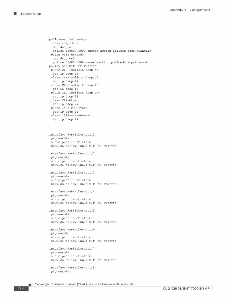
Appendix D Configurations Express Setup
!!policy-map Voice-Map class voip-data set dscp ef police 320000 8000 exceed-action policed-dscp-transmit class voip-control set dscp cs3 police 32000 8000 exceed-action policed-dscp-transmitpolicy-map CIP-PTP-Traffic class CIP-Implicit_dscp_55 set ip dscp 55 class CIP-Implicit_dscp_47 set ip dscp 47 class CIP-Implicit_dscp_43 set ip dscp 43 class CIP-Implicit_dscp_any set ip dscp 31 class CIP-Other set ip dscp 27 class 1588-PTP-Event set ip dscp 59 class 1588-PTP-General set ip dscp 47!!!interface FastEthernet1/1 ptp enable alarm profile ab-alarm service-policy input CIP-PTP-Traffic!interface FastEthernet1/2 ptp enable alarm profile ab-alarm service-policy input CIP-PTP-Traffic!interface FastEthernet1/3 ptp enable alarm profile ab-alarm service-policy input CIP-PTP-Traffic!interface FastEthernet1/4 ptp enable alarm profile ab-alarm service-policy input CIP-PTP-Traffic!interface FastEthernet1/5 ptp enable alarm profile ab-alarm service-policy input CIP-PTP-Traffic!interface FastEthernet1/6 ptp enable alarm profile ab-alarm service-policy input CIP-PTP-Traffic!interface FastEthernet1/7 ptp enable alarm profile ab-alarm service-policy input CIP-PTP-Traffic!interface FastEthernet1/8 ptp enable
D-4Converged Plantwide Ethernet (CPwE) Design and Implementation Guide
OL-21226-01, ENET-TD001E-EN-P
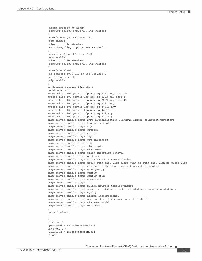
Appendix D Configurations Express Setup
alarm profile ab-alarm service-policy input CIP-PTP-Traffic!interface GigabitEthernet1/1 ptp enable alarm profile ab-alarm service-policy input CIP-PTP-Traffic!interface GigabitEthernet1/2 ptp enable alarm profile ab-alarm service-policy input CIP-PTP-Traffic!interface Vlan1 ip address 10.17.10.10 255.255.255.0 no ip route-cache cip enable!ip default-gateway 10.17.10.1ip http serveraccess-list 101 permit udp any eq 2222 any dscp 55access-list 102 permit udp any eq 2222 any dscp 47access-list 103 permit udp any eq 2222 any dscp 43access-list 104 permit udp any eq 2222 anyaccess-list 105 permit udp any eq 44818 anyaccess-list 105 permit tcp any eq 44818 anyaccess-list 106 permit udp any eq 319 anyaccess-list 107 permit udp any eq 320 anysnmp-server enable traps snmp authentication linkdown linkup coldstart warmstartsnmp-server enable traps transceiver allsnmp-server enable traps ttysnmp-server enable traps clustersnmp-server enable traps entitysnmp-server enable traps repsnmp-server enable traps cpu thresholdsnmp-server enable traps vtpsnmp-server enable traps vlancreatesnmp-server enable traps vlandeletesnmp-server enable traps flash insertion removalsnmp-server enable traps port-securitysnmp-server enable traps auth-framework sec-violationsnmp-server enable traps dot1x auth-fail-vlan guest-vlan no-auth-fail-vlan no-guest-vlansnmp-server enable traps envmon fan shutdown supply temperature statussnmp-server enable traps config-copysnmp-server enable traps configsnmp-server enable traps config-ctidsnmp-server enable traps energywisesnmp-server enable traps rtrsnmp-server enable traps bridge newroot topologychangesnmp-server enable traps stpx inconsistency root-inconsistency loop-inconsistencysnmp-server enable traps syslogsnmp-server enable traps alarms informationalsnmp-server enable traps mac-notification change move thresholdsnmp-server enable traps vlan-membershipsnmp-server enable traps errdisable!control-plane!!line con 0 password 7 1500040F0F3D2E2824line vty 0 4 password 7 1500040F0F3D2E2824 login
D-5Converged Plantwide Ethernet (CPwE) Design and Implementation Guide
OL-21226-01, ENET-TD001E-EN-P
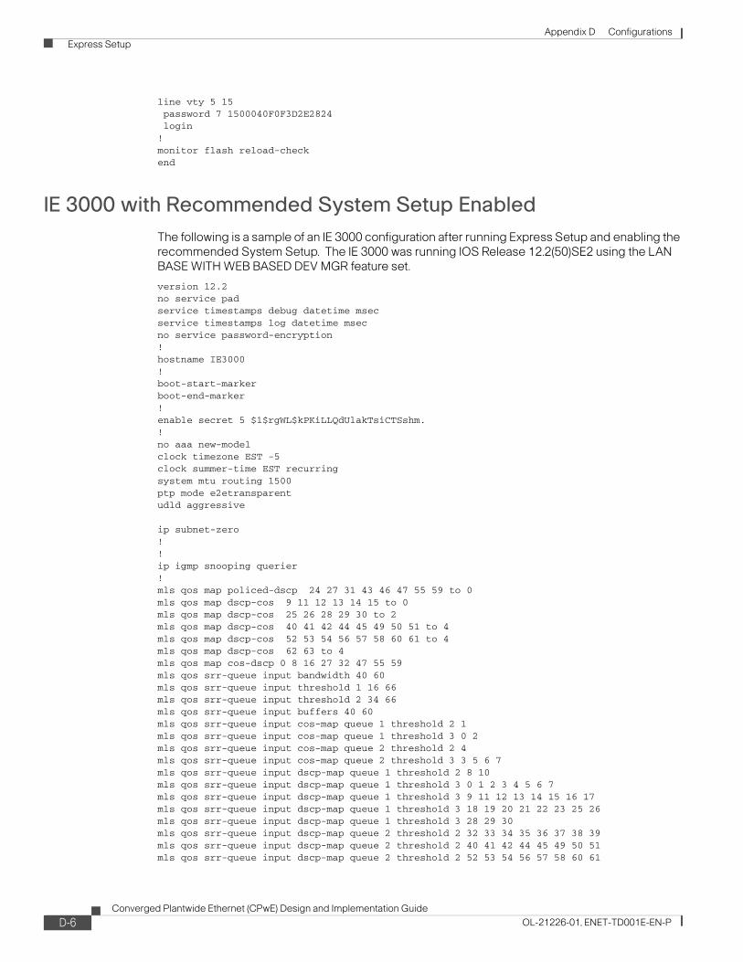
Appendix D Configurations Express Setup
line vty 5 15 password 7 1500040F0F3D2E2824 login!monitor flash reload-checkend
IE 3000 with Recommended System Setup EnabledThe following is a sample of an IE 3000 configuration after running Express Setup and enabling the recommended System Setup. The IE 3000 was running IOS Release 12.2(50)SE2 using the LAN BASE WITH WEB BASED DEV MGR feature set.
version 12.2no service padservice timestamps debug datetime msecservice timestamps log datetime msecno service password-encryption!hostname IE3000!boot-start-markerboot-end-marker!enable secret 5 $1$rgWL$kPKiLLQdUlakTsiCTSshm.!no aaa new-modelclock timezone EST -5clock summer-time EST recurringsystem mtu routing 1500ptp mode e2etransparent udld aggressive
ip subnet-zero!!ip igmp snooping querier!mls qos map policed-dscp 24 27 31 43 46 47 55 59 to 0mls qos map dscp-cos 9 11 12 13 14 15 to 0mls qos map dscp-cos 25 26 28 29 30 to 2mls qos map dscp-cos 40 41 42 44 45 49 50 51 to 4mls qos map dscp-cos 52 53 54 56 57 58 60 61 to 4mls qos map dscp-cos 62 63 to 4mls qos map cos-dscp 0 8 16 27 32 47 55 59mls qos srr-queue input bandwidth 40 60mls qos srr-queue input threshold 1 16 66mls qos srr-queue input threshold 2 34 66mls qos srr-queue input buffers 40 60 mls qos srr-queue input cos-map queue 1 threshold 2 1mls qos srr-queue input cos-map queue 1 threshold 3 0 2mls qos srr-queue input cos-map queue 2 threshold 2 4mls qos srr-queue input cos-map queue 2 threshold 3 3 5 6 7mls qos srr-queue input dscp-map queue 1 threshold 2 8 10mls qos srr-queue input dscp-map queue 1 threshold 3 0 1 2 3 4 5 6 7mls qos srr-queue input dscp-map queue 1 threshold 3 9 11 12 13 14 15 16 17mls qos srr-queue input dscp-map queue 1 threshold 3 18 19 20 21 22 23 25 26mls qos srr-queue input dscp-map queue 1 threshold 3 28 29 30mls qos srr-queue input dscp-map queue 2 threshold 2 32 33 34 35 36 37 38 39mls qos srr-queue input dscp-map queue 2 threshold 2 40 41 42 44 45 49 50 51mls qos srr-queue input dscp-map queue 2 threshold 2 52 53 54 56 57 58 60 61
D-6Converged Plantwide Ethernet (CPwE) Design and Implementation Guide
OL-21226-01, ENET-TD001E-EN-P

Appendix D Configurations Express Setup
mls qos srr-queue input dscp-map queue 2 threshold 2 62 63mls qos srr-queue input dscp-map queue 2 threshold 3 24 27 31 43 46 47 48 55mls qos srr-queue input dscp-map queue 2 threshold 3 59mls qos srr-queue output cos-map queue 1 threshold 3 7mls qos srr-queue output cos-map queue 2 threshold 2 1mls qos srr-queue output cos-map queue 2 threshold 3 0 2 4mls qos srr-queue output cos-map queue 3 threshold 3 5 6mls qos srr-queue output cos-map queue 4 threshold 3 3mls qos srr-queue output dscp-map queue 1 threshold 3 59mls qos srr-queue output dscp-map queue 2 threshold 2 8 10mls qos srr-queue output dscp-map queue 2 threshold 3 0 1 2 3 4 5 6 7mls qos srr-queue output dscp-map queue 2 threshold 3 9 11 12 13 14 15 16 17mls qos srr-queue output dscp-map queue 2 threshold 3 18 19 20 21 22 23 25 26mls qos srr-queue output dscp-map queue 2 threshold 3 28 29 30 32 33 34 35 36mls qos srr-queue output dscp-map queue 2 threshold 3 37 38 39 40 41 42 44 45mls qos srr-queue output dscp-map queue 2 threshold 3 49 50 51 52 53 54 56 57mls qos srr-queue output dscp-map queue 2 threshold 3 58 60 61 62 63mls qos srr-queue output dscp-map queue 3 threshold 3 43 46 47 48 55mls qos srr-queue output dscp-map queue 4 threshold 3 24 27 31mls qos queue-set output 1 buffers 10 25 40 25mls qos queue-set output 2 buffers 10 25 40 25no mls qos rewrite ip dscpmls qos!crypto pki trustpoint HTTPS_SS_CERT_KEYPAIR enrollment selfsigned serial-number revocation-check none rsakeypair HTTPS_SS_CERT_KEYPAIR!!crypto pki certificate chain HTTPS_SS_CERT_KEYPAIR certificate self-signed 01 30820253 308201BC A0030201 02020101 300D0609 2A864886 F70D0101 04050030 3B311030 0E060355 04031307 49453330 30302E31 27300F06 03550405 13083143 33303841 38303014 06092A86 4886F70D 01090216 07494533 3030302E 301E170D 30393036 31373132 30393335 5A170D32 30303130 31303030 3030305A 303B3110 300E0603 55040313 07494533 3030302E 3127300F 06035504 05130831 43333038 41383030 1406092A 864886F7 0D010902 16074945 33303030 2E30819F 300D0609 2A864886 F70D0101 01050003 818D0030 81890281 8100D1FD F4FED5F3 C28A8DDC 864A2BF1 3D7D8853 64AB3775 0DB46748 938FDA4A 430B03B7 F01A939F 5F3A5BD0 B20A182D D1AA826A 47B25679 85814D80 EFE26FFA 9AE20F8C 5CCE680E F23807FB 3CC016D8 37385B12 F7D3EC82 D77A342F 2275092C 8CDD5E06 080B9312 930A3A66 4572668E 3389E090 B9F18B63 DB927ADE 9752C2FD 3A570203 010001A3 67306530 0F060355 1D130101 FF040530 030101FF 30120603 551D1104 0B300982 07494533 3030302E 301F0603 551D2304 18301680 14443056 FBDE73C1 1766C192 3BCE4455 590E2CC2 A0301D06 03551D0E 04160414 443056FB DE73C117 66C1923B CE445559 0E2CC2A0 300D0609 2A864886 F70D0101 04050003 81810082 A8454321 5ECDA2F5 574A48B7 A97324BD 357ED4DD 1BC8A1FF F9DB3AE9 FD9C134E F3C63CC7 CF613C41 1D5F54D0 DEE2D8AC 5DD0DF81 52427FB0 CF53DF62 853CBA04 E893D820 221A2F6B 638098E1 41EFC650 7BE0601A 06472FD9 E85B0F26 AC91C92F C6E6962D DD8123EE 5112A029 3E43F872 54A2CE84 B3F1A045 845C40A0 6FD8C7 quit!!macro global description cisco-global | cisco-ie-global | cisco-ie-qos-map-setup | cisco-ie-qos-queue-setup!!!errdisable recovery cause link-flaperrdisable recovery interval 60no mac authenticationmac authentication table version 0
D-7Converged Plantwide Ethernet (CPwE) Design and Implementation Guide
OL-21226-01, ENET-TD001E-EN-P

Appendix D Configurations Express Setup
!spanning-tree mode mstspanning-tree loopguard defaultspanning-tree EtherChannel guard misconfigspanning-tree extend system-id!alarm profile defaultPort alarm 3 syslog 3 notifies 3 !alarm facility temperature primary relay major alarm facility temperature primary syslog alarm facility temperature primary notifies !vlan internal allocation policy ascending!!class-map match-all 1588-PTP-General match access-group 107class-map match-all 1588-PTP-Event match access-group 106class-map match-all CIP-Implicit_dscp_any match access-group 104class-map match-all CIP-Other match access-group 105class-map match-all voip-data match ip dscp ef class-map match-all voip-control match ip dscp cs3 af31 class-map match-all CIP-Implicit_dscp_43 match access-group 103class-map match-all CIP-Implicit_dscp_55 match access-group 101class-map match-all CIP-Implicit_dscp_47 match access-group 102!!policy-map Voice-Map class voip-data set dscp ef police 320000 8000 exceed-action policed-dscp-transmit class voip-control set dscp cs3 police 32000 8000 exceed-action policed-dscp-transmitpolicy-map CIP-PTP-Traffic class CIP-Implicit_dscp_55 set ip dscp 55 class CIP-Implicit_dscp_47 set ip dscp 47 class CIP-Implicit_dscp_43 set ip dscp 43 class CIP-Implicit_dscp_any set ip dscp 31 class CIP-Other set ip dscp 27 class 1588-PTP-Event set ip dscp 59 class 1588-PTP-General set ip dscp 47!!!interface FastEthernet1/1
D-8Converged Plantwide Ethernet (CPwE) Design and Implementation Guide
OL-21226-01, ENET-TD001E-EN-P

Appendix D Configurations Express Setup
ptp enable!interface FastEthernet1/2 ptp enable!interface FastEthernet1/3 ptp enable!interface FastEthernet1/4 ptp enable!interface GigabitEthernet1/1 ptp enable!interface GigabitEthernet1/2 ptp enable!interface Vlan1 ip address 10.17.10.11 255.255.255.0 no ip route-cache cip enable!ip default-gateway 10.17.10.1ip http serverip http secure-serveraccess-list 101 permit udp any eq 2222 any dscp 55access-list 102 permit udp any eq 2222 any dscp 47access-list 103 permit udp any eq 2222 any dscp 43access-list 104 permit udp any eq 2222 anyaccess-list 105 permit udp any eq 44818 anyaccess-list 105 permit tcp any eq 44818 anyaccess-list 106 permit udp any eq 319 anyaccess-list 107 permit udp any eq 320 any!control-plane!!line con 0line vty 0 4 password rockwell loginline vty 5 15 password rockwell login!monitor flash reload-checkend
D-9Converged Plantwide Ethernet (CPwE) Design and Implementation Guide
OL-21226-01, ENET-TD001E-EN-P

Appendix D Configurations Smartports
Smartports
Stratix 8000
Automation Device
The Automation Device Smartport should be used for any EtherNet/IP devices. This includes controllers, HMI displays, distributed I/O, etc. The Automation Device Smartport enables the following features:
• Sets the port to host mode
• Enables MAC flooding attack protection
• Sets the VLAN number
• Enables the automation QoS policy
• Configures the output queues
• Enables the alarm profile
• Disables Cisco Discovery Protocol (CDP)
Macro name : ab-ethernetipMacro type : default interface# macro keywords $access_vlan#macro description ab-ethernetipswitchport hostswitchport port-securityswitchport port-security maximum 1switchport port-security violation restrictswitchport port-security aging type inactivityswitchport access vlan $access_vlanservice-policy input CIP-PTP-Trafficpriority-queue outsrr-queue bandwidth share 1 19 40 40alarm profile ab-alarmload-interval 30no cdp enable
Automation Device with QoS
The Automation Device with QoS should be used for CIP Sync and CIP Motion devices. The Automation Device with QoS Smartport enables the following features:
• Sets the port in trunk mode
• Enables Spanning Tree Portfast
• Disables Dynamic Trunking Protocol (DTP)
• Sets the native VLAN number
• Enables MAC flooding attack protection
• Enables the automation QoS policy
• Configures the output queues
D-10Converged Plantwide Ethernet (CPwE) Design and Implementation Guide
OL-21226-01, ENET-TD001E-EN-P

Appendix D Configurations Smartports
• Enables the alarm profile
• Disables Cisco Discovery Protocol (CDP)
• Sets the port to trust DSCP
Macro name : ab-syncmotionMacro type : default interface#macro keywords $native_vlan#macro name ab-syncmotion#macro description ab-syncmotionswitchport mode trunkspanning-tree portfast trunkswitchport nonegotiateswitchport trunk native vlan $native_vlanswitchport port-securityswitchport port-security maximum 1switchport port-security violation restrictswitchport port-security aging type inactivityservice-policy input CIP-PTP-Trafficpriority-queue outsrr-queue bandwidth share 1 19 40 40alarm profile ab-alarmload-interval 30no cdp enablemls qos trust dscp
Desktop for Automation
The Desktop for Automation Smartport should be used for PCs used on the Cell/Area zone EtherNet/IP network. It should not be used for any systems running virtual machines with out turning the port security configuration off. If the Desktop for Automation Smartport is used with a virtual machine, the port security configuration will need to be modified using CNA or CLI. The Desktop for Automation Smartport enables the following features:
• Sets the port in access mode
• Set the VLAN number
• Enables MAC flooding attack protection
• Enables Spanning Tree Portfast
• Enables Spanning Tree BPDU Guard
• Enables the automation QoS policy
• Sets the alarm profile
Macro name : desktop-automationMacro type : default interface#macro keywords $access_vlan#macro name desktop-automationswitchport mode accessswitchport access vlan $access_vlanswitchport port-securityswitchport port-security maximum 1switchport port-security aging time 2switchport port-security violation restrictswitchport port-security aging type inactivityspanning-tree portfastspanning-tree bpduguard enable
D-11Converged Plantwide Ethernet (CPwE) Design and Implementation Guide
OL-21226-01, ENET-TD001E-EN-P

Appendix D Configurations Smartports
service-policy input CIP-PTP-Trafficno alarm profilealarm profile ab-alarm
Switch for Automation
The Switch for Automation Smartport is used on ports that connect to other managed Ethernet switches. The Switch for Automation enables the following features:
• Sets the port in trunk mode
• Sets the native VLAN
• Sets Spanning Tree to use a point-to-point link
• Sets the port to trust COS
• Enables the automation QoS policy
• Configures the output queues
• Sets the alarm profile
Macro name : switch-automationMacro type : default interface#macro keywords $native_vlan#macro name: switch-automationswitchport mode trunkswitchport trunk native vlan $native_vlanspanning-tree link-type point-to-pointmls qos trust cosservice-policy input CIP-PTP-Trafficpriority-queue outsrr-queue bandwidth share 1 19 40 40no alarm profilealarm profile ab-alarm
The switch for Automation Smartport does not disable DTP. This must be done manually with the switchport nonegotiate interface configuration command.
Router for Automation
The Router for Automation Smartport is used on ports that connect to routers such as the Cisco 2800 Series ISR. The Router for Automation Smartport enables the following features:
• Sets the port in trunk mode
• Sets the native VLAN
• Enables Spanning Tree Portfast
• Enables Spanning Tree BPDU Guard
• Sets the port to trust DSCP
• Enables the automation QoS policy
• Configures the output queues
• Sets the alarm profile
Macro name : router-automationMacro type : default interface
D-12Converged Plantwide Ethernet (CPwE) Design and Implementation Guide
OL-21226-01, ENET-TD001E-EN-P

Appendix D Configurations Smartports
#macro keywords $native_vlan#Macro name router-automationswitchport mode trunkswitchport trunk native vlan $native_vlanspanning-tree portfast trunkspanning-tree bpduguard enablemls qos trust dscpservice-policy input CIP-PTP-Trafficpriority-queue outsrr-queue bandwidth share 1 19 40 40no alarm profilealarm profile ab-alarm
Phone for Automation
The Phone for Automation Smartport is used on ports that connect to a VoIP phone. The Phone for Automation Smartport enables the following features:
• Sets the port in access mode
• Sets the voice and data VLANs
• Enables MAC Flooding protection
• Enables Spanning Tree Portfast
• Enables Spanning Tree BPDU Guard
• Enables the VoIP QoS policy
• Configures the output queues
• Sets the alarm profile
Macro name : phone-automationMacro type : default interface#macro keywords: $access_vlan $voice_vlan#macro name phone-automationswitchport mode accessswitchport access vlan $access_vlanswitchport voice vlan $voice_vlanswitchport port-securityswitchport port-security maximum 2switchport port-security aging time 2switchport port-security violation restrictswitchport port-security aging type inactivityno service-policy input CIP-PTP-Trafficspanning-tree portfastspanning-tree bpduguard enableservice-policy input Voice-Mapsrr-queue bandwidth share 10 10 60 20no alarm profilealarm profile ab-alarm
D-13Converged Plantwide Ethernet (CPwE) Design and Implementation Guide
OL-21226-01, ENET-TD001E-EN-P

Appendix D Configurations Smartports
Wireless for Automation
The Wireless for Automation Smartport is used on ports that connect to wireless access points or Wireless LAN Controllers. The Wireless for Automation Smartport enables the following features:
• Sets the port in trunk mode
• Sets the native VLAN
• Disables Dynamic Trunking Protocol (DTP)
• Enables Spanning Tree BPDU Guard
• Sets the port to trust COS
• Enables the Automation QoS policy
• Configures the output queues
• Sets the alarm profile
Macro name : wireless-automationMacro type : default interface#macro keywords: $native_vlan #macro name: wireless-automationswitchport mode trunkswitchport trunk native vlan $native_vlanswitchport nonegotiatespanning-tree bpduguard enablemls qos trust cosservice-policy input CIP-PTP-Trafficsrr-queue bandwidth share 1 19 40 40no alarm profilealarm profile ab-alarm
Port Mirroring
The Port Mirroring Smartport is used to mirror traffic from one interface to another. This feature is used in conjunction with a network traffic analyzer to troubleshoot system and application problems.
None
The None Smartport is used to clear all Smartport configurations from the port.
IE 3000
IE Desktop
The IE Desktop Smartport is used on ports that have a single desktop computer connected. The IE Desktop Smartport enables the following features:
• Sets the port to access mode
• Sets the VLAN number
• Enables MAC Address Flooding protection
D-14Converged Plantwide Ethernet (CPwE) Design and Implementation Guide
OL-21226-01, ENET-TD001E-EN-P

Appendix D Configurations Smartports
• Enables Spanning Tree Portfast
• Enables Spanning Tree BPDU Guard
Macro name : cisco-ie-desktopMacro type : default interface# macro keywords $access_vlan#macro name cisco-ie-desktopswitchport mode accessswitchport access vlan $access_vlanswitchport port-securityswitchport port-security maximum 1switchport port-security aging time 2switchport port-security violation restrictswitchport port-security aging type inactivityspanning-tree portfastspanning-tree bpduguard enable
IE Switch
The IE Switch Smartport is used on ports that connect to other switches. The IE Switch enables the following features:
• Sets the port to trunk mode
• Sets the native VLAN
• Sets the Spanning Tree link type to point-to-point
• Sets the port to trust CoS
• Enables the Automation QoS policy
• Configures the output queues.
Macro name : cisco-ie-switchMacro type : default interface# macro keywords $native_vlan#macro name: cisco-ie-switchswitchport mode trunkswitchport trunk native vlan $native_vlanspanning-tree link-type point-to-pointmls qos trust cosservice-policy input CIP-PTP-Trafficpriority-queue outsrr-queue bandwidth share 1 19 40 40
The switch for Automation Smartport does not disable DTP. This must be done manually with the switchport nonegotiate interface configuration command.
IE Router
The IE Router Smartport is used on ports that connect to Cisco routers such as the 2800 Series ISR. The IE Router smartport enables the following features:
• Sets the port to trunk mode
• Sets the native VLAN
• Enables Spanning Tree Portfast
• Enables Spanning Tree BPDU Guard
D-15Converged Plantwide Ethernet (CPwE) Design and Implementation Guide
OL-21226-01, ENET-TD001E-EN-P

Appendix D Configurations Smartports
• Sets the port to trust DSCP
• Enables the automation QoS policy
• Configures the output queues
Macro name : cisco-ie-routerMacro type : default interface# macro keywords $native_vlan#Macro name cisco-ie-routerswitchport mode trunkswitchport trunk native vlan $native_vlanspanning-tree portfast trunkspanning-tree bpduguard enablemls qos trust dscpservice-policy input CIP-PTP-Trafficpriority-queue outsrr-queue bandwidth share 1 19 40 40
IE Phone
The IE Phone Smartport is used to connect VoIP phones to the switch. The IE Phone Smartport enables the following features:
• Sets the switch port to access mode
• Sets the voice and data VLANs
• Enables MAC Address Flooding protection
• Enables Spanning Tree Portfast
• Enables Spanning Tree BPDU Guard
• Sets the port to trust the CoS from the phone
• Sets the VoIP service policy
• Configures the output queues
Macro name : cisco-ie-phoneMacro type : default interface# macro keywords $access_vlan $voice_vlan#macro name cisco-ie-phoneswitchport mode accessswitchport access vlan $access_vlanswitchport voice vlan $voice_vlanswitchport port-securityswitchport port-security maximum 2switchport port-security aging time 2switchport port-security violation restrictswitchport port-security aging type inactivityspanning-tree portfastspanning-tree bpduguard enableno service-policy input CIP-PTP-Trafficmls qos trust device cisco-phonemls qos trust cosservice-policy input Voice-Mapsrr-queue bandwidth share 10 10 60 20
D-16Converged Plantwide Ethernet (CPwE) Design and Implementation Guide
OL-21226-01, ENET-TD001E-EN-P

Appendix D Configurations Smartports
IE Wireless
The IE Wireless Smartport is used to connect to Access Points and Wireless LAN Controllers. The IE Wireless Smartport enables the following features:
• Set the port to trunk mode
• Set the native VLAN
• Disable Dynamic Trunking Protocol (DTP)
• Enables Spanning Tree BPDU Guard
• Set the port to trust CoS
• Configures the output queues
Macro name : cisco-ie-wirelessMacro type : default interface#macro keywords $native_vlan#macro name: cisco-ie-wirelessswitchport mode trunkswitchport trunk native vlan $native_vlanswitchport nonegotiatespanning-tree bpduguard enablemls qos trust cossrr-queue bandwidth share 1 19 40 40
Cisco EtherNet/IP
The Cisco EtherNet/IP Smartport is used to connect to EtherNet/IP devices such as PAC, distributed I/O, etc. The Cisco EtherNet/IP Smartport enables the following features:
• Sets the port to host
• Sets the access VLAN
• Enables broadcast storm control
• Enables the Automation service policy
• Configures the output queues
Macro name : cisco-ethernetipMacro type : default interface#macro keywords $access_vlan#macro name cisco-ethernetip#macro description cisco-ethernetipswitchport hostswitchport access vlan $access_vlanstorm-control broadcast level 3.00 1.00service-policy input CIP-PTP-Trafficpriority-queue outsrr-queue bandwidth share 1 19 40 40
D-17Converged Plantwide Ethernet (CPwE) Design and Implementation Guide
OL-21226-01, ENET-TD001E-EN-P

Appendix D Configurations Smartports
Diagnostics
The Diagnostics Smartport is used to mirror traffic from one interface to another. This feature is used in conjunction with a network traffic analyzer to troubleshoot system and application problems.
None
The None Smartport is used to clear all Smartport configurations from the port.
D-18Converged Plantwide Ethernet (CPwE) Design and Implementation Guide
OL-21226-01, ENET-TD001E-EN-P

Converged Plantwide Ethernet (CPwOL-21226-01, ENET-TD001E-EN-P
A P P E N D I X E
Reference DocumentsFor information on SSH configuration, refer to the following URL:
http://www.cisco.com/en/US/partner/tech/tk583/tk617/technologies_tech_note09186a00800949e2.shtml
For information on management interface configuration, refer to the following URL:
http://www.cisco.com/en/US/partner/products/hw/switches/ps700/products_tech_note09186a008010e9ca.shtml#topic7
For information on switch images, refer to the following URL:
http://www.cisco.com/en/US/partner/products/hw/switches/ps700/products_tech_note09186a008015bfab.shtml
For information on understanding and troubleshooting HSRP problems in Catalyst switch networks, refer to the following URL:
http://www.cisco.com/en/US/partner/tech/tk648/tk362/technologies_tech_note09186a0080094afd.shtml
E-1E) Design and Implementation Guide
Appendix E Reference Documents About Cisco Validated Design (CVD) Program
About Cisco Validated Design (CVD) ProgramThe CVD program consists of systems and solutions designed, tested, and documented to facilitate faster, more reliable, and more predictable customer deployments. For more information visit www.cisco.com/go/designzone.
ALL DESIGNS, SPECIFICATIONS, STATEMENTS, INFORMATION, AND RECOMMENDATIONS (COLLECTIVELY, "DESIGNS") IN THIS MANUAL ARE PRESENTED "AS IS," WITH ALL FAULTS. CISCO AND ITS SUPPLIERS DISCLAIM ALL WARRANTIES, INCLUDING, WITHOUT LIMITATION, THE WARRANTY OF MERCHANTABILITY, FITNESS FOR A PARTICULAR PURPOSE AND NONINFRINGEMENT OR ARISING FROM A COURSE OF DEALING, USAGE, OR TRADE PRACTICE. IN NO EVENT SHALL CISCO OR ITS SUPPLIERS BE LIABLE FOR ANY INDIRECT, SPECIAL, CONSEQUENTIAL, OR INCIDENTAL DAMAGES, INCLUDING, WITHOUT LIMITATION, LOST PROFITS OR LOSS OR DAMAGE TO DATA ARISING OUT OF THE USE OR INABILITY TO USE THE DESIGNS, EVEN IF CISCO OR ITS SUPPLIERS HAVE BEEN ADVISED OF THE POSSIBILITY OF SUCH DAMAGES.
THE DESIGNS ARE SUBJECT TO CHANGE WITHOUT NOTICE. USERS ARE SOLELY RESPONSIBLE FOR THEIR APPLICATION OF THE DESIGNS. THE DESIGNS DO NOT CONSTITUTE THE TECHNICAL OR OTHER PROFESSIONAL ADVICE OF CISCO, ITS SUPPLIERS OR PARTNERS. USERS SHOULD CONSULT THEIR OWN TECHNICAL ADVISORS BEFORE IMPLEMENTING THE DESIGNS. RESULTS MAY VARY DEPENDING ON FACTORS NOT TESTED BY CISCO.
CCDE, CCENT, Cisco Eos, Cisco Lumin, Cisco Nexus, Cisco StadiumVision, Cisco TelePresence, Cisco WebEx, the Cisco logo, DCE, andWelcome to the Human Network are trademarks; Changing the Way We Work, Live, Play, and Learn and Cisco Store are service marks; and AccessRegistrar, Aironet, AsyncOS, Bringing the Meeting To You, Catalyst, CCDA, CCDP, CCIE, CCIP, CCNA, CCNP, CCSP, CCVP, Cisco, the CiscoCertified Internetwork Expert logo, Cisco IOS, Cisco Press, Cisco Systems, Cisco Systems Capital, the Cisco Systems logo, Cisco Unity,Collaboration Without Limitation, EtherFast, EtherSwitch, Event Center, Fast Step, Follow Me Browsing, FormShare, GigaDrive, HomeLink,Internet Quotient, IOS, iPhone, iQuick Study, IronPort, the IronPort logo, LightStream, Linksys, MediaTone, MeetingPlace, MeetingPlace ChimeSound, MGX, Networkers, Networking Academy, Network Registrar, PCNow, PIX, PowerPanels, ProConnect, ScriptShare, SenderBase,SMARTnet, Spectrum Expert, StackWise, The Fastest Way to Increase Your Internet Quotient, TransPath, WebEx, and the WebEx logo areregistered trademarks of Cisco Systems, Inc. and/or its affiliates in the United States and certain other countries.
All other trademarks mentioned in this document or website are the property of their respective owners. The use of the word partner does not implya partnership relationship between Cisco and any other company. (0809R)
© 2011 Cisco Systems, Inc. All rights reserved
Cisco is the worldwide leader in networking that transforms how people connect, communicate and collaborate. Information about Cisco can be found at www.cisco.com. For ongoing news, please go to http://newsroom.cisco.com. Cisco equipment in Europe is supplied by Cisco Systems International BV, a wholly owned subsidiary of Cisco Systems, Inc.
www.cisco.com
Americas HeadquartersCisco Systems, Inc.San Jose, CA
Asia Pacific HeadquartersCisco Systems (USA) Pte. Ltd.Singapore
Europe HeadquartersCisco Systems International BVAmsterdam, The Netherlands
Cisco has more than 200 offices worldwide. Addresses, phone numbers, and fax numbers are listed on the Cisco Website at www.cisco.com/go/offices.
CCDE, CCENT, Cisco Eos, Cisco HealthPresence, the Cisco logo, Cisco Lumin, Cisco Nexus, Cisco StadiumVision, Cisco TelePresence, Cisco WebEx, DCE, and Welcome to the Human Network are trademarks; Changing theWay We Work, Live, Play, and Learn and Cisco Store are service marks; and Access Registrar, Aironet, AsyncOS, Bringing the Meeting To You, Catalyst, CCDA, CCDP, CCIE, CCIP, CCNA, CCNP, CCSP, CCVP, Cisco, the CiscoCertified Internetwork Expert logo, Cisco IOS, Cisco Press, Cisco Systems, Cisco Systems Capital, the Cisco Systems logo, Cisco Unity, Collaboration Without Limitation, EtherFast, EtherSwitch, Event Center, Fast Step, FollowMe Browsing, FormShare, GigaDrive, HomeLink, Internet Quotient, IOS, iPhone, iQuick Study, IronPort, the IronPort logo, LightStream, Linksys, MediaTone, MeetingPlace, MeetingPlace Chime Sound, MGX, Networkers, Net-working Academy, Network Registrar, PCNow, PIX, PowerPanels, ProConnect, ScriptShare, SenderBase, SMARTnet, Spectrum Expert, StackWise, The Fastest Way to Increase Your Internet Quotient, TransPath, WebEx, and theWebEx logo are registered trademarks of Cisco Systems, Inc. and/or its affiliates in the United States and certain other countries.
All other trademarks mentioned in this document or website are the property of their respective owners. The use of the word partner does not imply a partnership relationship between Cisco and any other company. (0812R)
Rockwell Automation is a leading provider of power, control and information solutions that enable customers to get products to market faster, reduce their total cost of ownership, better utilize plant assets, and minimize risks in their manufacturing environments.
www.rockwellautomation.com
Americas:Rockwell Automation1201 South Second Street Milwaukee, WI 53204-2496 USA Tel: (1) 414.382.2000, Fax: (1) 414.382.4444
Asia Pacific:Rockwell AutomationLevel 14, Core F, Cyberport 3 100 Cyberport Road, Hong Kong Tel: (852) 2887 4788, Fax: (852) 2508 1846
Europe/Middle East/Africa: Rockwell AutomationVorstlaan/Boulevard du Souverain 36 1170 Brussels, Belgium Tel: (32) 2 663 0600, Fax: (32) 2 663 0640
© 2011 Cisco Systems, Inc. and Rockwell Automation, Inc. All rights reserved.Published: January 22, 2010Updated: September 9, 2011