Cisco - Configuring and Analyzing Clustering on Catalyst Fixed … · Configuring and Analyzing...
41
Configuring and Analyzing Clustering on Catalyst Fixed Configuration Switches Document ID: 4085 Contents Introduction Prerequisites Requirements Components Used Conventions Important Notes Command Switch Characteristics Standby Command Switch Characteristics Candidate Switch and Member Switch Characteristics Catalyst Switch Models with Cluster Capabilities Cluster Management Protocol Configure Clustering Lab Scenarios Create Clusters with Cluster Management Suite Add a Member in an Existing Cluster debug and show Commands Sample show Command Output Sample debug Command Output Appendix Cluster Sample Configurations Additional Information NetPro Discussion Forums - Featured Conversations Related Information Introduction This document describes the basic configuration steps to form a cluster on the Catalyst 1900/2820 and Catalyst fixed configuration switches with use of the Cluster Management Suite (CMS). The Catalyst fixed configuration switches that this document covers include the 2900/3500XL, 2940, 2950, 2955, 2970, 3550, 3560, and 3750 series. The intent of this document is to provide basic knowledge on how clustering works and to provide basic troubleshoot and analyze procedures with show commands and debug outputs. The document gives a simple example of a cluster build with use of the Web Interface. It also shows automatic configuration changes, noticeable during the cluster build process. Prerequisites Requirements A separate Web Management document provides information on how to access the switch with Cisco Visual Switch Manager (VSM) or CMS. The document, Troubleshooting Cisco Visual Switch Manager or Cluster Management Suite Access on the Catalyst 2900 XL/3500 XL/2950/3550 Switch, addresses these problems: Unable to connect to the main web page of the switch ● 404 Not Found errors ● Cisco - Configuring and Analyzing Clustering on Catalyst Fixed Configuration Switches http://www.cisco.com/warp/customer/473/61.html (1 of 41) [11/18/2004 10:44:08 AM]
Transcript of Cisco - Configuring and Analyzing Clustering on Catalyst Fixed … · Configuring and Analyzing...

Configuring and Analyzing Clustering on CatalystFixed Configuration SwitchesDocument ID: 4085
ContentsIntroductionPrerequisites Requirements Components Used ConventionsImportant Notes Command Switch Characteristics Standby Command Switch Characteristics Candidate Switch and Member Switch Characteristics Catalyst Switch Models with Cluster Capabilities Cluster Management ProtocolConfigure Clustering Lab Scenarios Create Clusters with Cluster Management Suite Add a Member in an Existing Clusterdebug and show Commands Sample show Command Output Sample debug Command OutputAppendix Cluster Sample Configurations Additional InformationNetPro Discussion Forums - Featured ConversationsRelated Information
IntroductionThis document describes the basic configuration steps to form a cluster on the Catalyst 1900/2820 and Catalyst fixed configuration switches withuse of the Cluster Management Suite (CMS). The Catalyst fixed configuration switches that this document covers include the 2900/3500XL,2940, 2950, 2955, 2970, 3550, 3560, and 3750 series. The intent of this document is to provide basic knowledge on how clustering works and toprovide basic troubleshoot and analyze procedures with show commands and debug outputs. The document gives a simple example of a clusterbuild with use of the Web Interface. It also shows automatic configuration changes, noticeable during the cluster build process.
Prerequisites
Requirements
A separate Web Management document provides information on how to access the switch with Cisco Visual Switch Manager (VSM) or CMS.The document, Troubleshooting Cisco Visual Switch Manager or Cluster Management Suite Access on the Catalyst 2900 XL/3500 XL/2950/3550Switch, addresses these problems:
Unable to connect to the main web page of the switch●
404 Not Found errors●
Cisco - Configuring and Analyzing Clustering on Catalyst Fixed Configuration Switches
http://www.cisco.com/warp/customer/473/61.html (1 of 41) [11/18/2004 10:44:08 AM]

A blank screen when you access VSM or CMS●
Java is not enabled screen●
Web Interface continually asks user name and password●
No response from device messages during link or bandwidth graphs creation●
Refer to Troubleshooting Cisco Visual Switch Manager or Cluster Management Suite Access on the Catalyst 2900 XL/3500 XL/2950/3550Switch if you have access problems with the Web-Based Management Interface (VSM or CMS) or if you notice any of these symptoms.
Components Used
This document is not restricted to specific software and hardware versions.
Conventions
For more information on document conventions, refer to the Cisco Technical Tips Conventions.
Important NotesCisco Switch Clustering Technology is a set of software features available to all 2900/3500XL, 2940, 2950, 2955, 2970, 3550, 3560, and 3750series switches and the Catalyst 1900/2820 Standard and Enterprise Edition switches. Clustering technology enables up to a maximum of 16interconnected switches to form a managed, single-IP address network. It is essentially a method to manage a group of switches without the needto assign an IP address to every switch.
Switches within a cluster have one of these roles:
Command switch●
Member switches●
Candidate switches●
In each cluster, there is a master switch called a command switch. The rest of the switches serve as member switches. The command switchprovides the primary management interface for the entire cluster. The command switch is typically the only switch within the switch clusterconfigured with an IP address. Each management request goes to the command switch before redirection to the appropriate member switch. Forredundancy, you can configure a standby command switch. The standby command switch must be the same model as the command switch. Amember switch typically is not configured with an IP address and receives management commands that the command switch has redirected. Acandidate switch is a switch that you can add to the switch cluster as a member switch.
Command Switch Characteristics
A Catalyst command switch must meet these requirements:
The switch has an IP address.●
The switch has Cisco Discovery Protocol version 2 (CDPv2) enabled (the default).●
The switch is not a command or member switch of another cluster.●
The switch connects to the standby command switches through the management VLAN and to the member switches through a commonVLAN.
●
The highest-end, command-capable switch in the cluster should be the command switch, as detailed here:
If your switch cluster has a 3750 switch, that switch should be the command switch.●
If your switch cluster has 2900XL, 2940, 2950, 2955, 3550, 3560 and 3500XL switches, the 3550 or the 3560 should be the commandswitch.
●
If your switch cluster has 2900XL, 2940, 2950, 2955, and 3500XL switches, the 2950 or the 2955 should be the command switch.●
If your switch cluster has 1900, 2820, 2900XL, and 3500XL switches, either the 2900XL or 3500XL should be the command switch.●
Cisco - Configuring and Analyzing Clustering on Catalyst Fixed Configuration Switches
http://www.cisco.com/warp/customer/473/61.html (2 of 41) [11/18/2004 10:44:08 AM]

Standby Command Switch Characteristics
A Catalyst standby command switch must meet these requirements:
The switch has an IP address.●
The switch has CDPv2 enabled.●
The switch is connected to other standby switches through the management VLAN and to all member switches through a common VLAN.●
The switch is redundantly connected to the cluster to maintain connectivity to member switches.●
The switch is not a command or member switch of another cluster.●
Standby command switches also must meet these requirements:
When the command switch is a 3750 switch, all standby command switches must be 3750 switches.●
When the command switch is a 3550 switch, all standby command switches must be 3550 switches.●
When the command switch is a 2955 switch, all standby command switches must be 2955 switches.●
When the command switch is a 2950 Long-Reach Ethernet (LRE) switch, all standby command switches must be 2950 LRE switches.●
When the command switch is a non-LRE 2950 switch that runs Cisco IOS® Software Release 12.1(9)EA1 or later, all standby commandswitches must be non-LRE 2950 switches that run Cisco IOS Software Release 12.1(9)EA1 or later.
●
When the command switch is a non-LRE 2950 switch that runs Cisco IOS Software Release 12.1(6)EA2 or later, all standby commandswitches must be non-LRE 2950 switches that run Cisco IOS Software Release 12.1(6)EA2 or later.
●
When the command switch runs Cisco IOS Software Release 12.0(5)WC2 or earlier, the standby command switches can be 2900XL,non-LRE 2950, and 3500XL switches.
●
The command switch and standby command switches should be of the same switch platform.
With a 3550 command switch, the standby command switches should be 3550 switches.●
With a 2955 command switch, the standby command switches should be 2955 switches.●
With a 2950 LRE command switch, the standby command switches should be 2950 LRE switches.●
With a non-LRE 2950 command switch, the standby command switches should be non-LRE 2950 switches.●
With a 2900XL or 3500XL command switch, the standby command switches should be 2900XL and 3500XL switches.●
Candidate Switch and Member Switch Characteristics
Candidate switches are cluster-capable switches that have not yet been added to a cluster. Member switches are switches that have actually beenadded to a switch cluster. Although not required, a candidate or member switch can have an IP address and password. (For related considerations,refer to the IP Addresses section and the Passwords section of the document Clustering Switches.)
To join a cluster, a candidate switch must meet these requirements:
The switch currently runs cluster-capable software.●
The switch has CDPv2 enabled.●
The switch is not a command or member switch of another cluster.●
The switch connects to the command switch through at least one common VLAN.●
If a cluster standby group exists, the switch connects to every standby command switch through at least one common VLAN. The VLAN toeach standby command switch can differ.
●
Note: These candidate and member switches must connect to the command switch and standby command switches through the managementVLAN:
1900 switches●
2820 switches●
2900XL switches●
non-LRE 2950 switches that currently run a release earlier than Cisco IOS Software Release 12.1(9)EA1●
Cisco - Configuring and Analyzing Clustering on Catalyst Fixed Configuration Switches
http://www.cisco.com/warp/customer/473/61.html (3 of 41) [11/18/2004 10:44:08 AM]
3500XL switches●
Note: This requirement does not apply if you have a non-LRE 2950 command switch that currently runs Cisco IOS Software Release 12.1(9)EA1or later, a 2950 LRE command switch, a 2955 command switch, or a 3550 command switch. Candidate and member switches can connect throughany VLAN in common with the command switch.
With CDPv2, all switches, including the command switch, discover CDP neighbors and store this information in the respective CDP neighborcache. Switches that run cluster-capable software pass the information about the switches and respective neighbors to the command switch. To dothis, the switches use the Intra-Cluster Communication (ICC) mechanism, which runs on top of User Datagram Protocol (UDP). The commandswitch filters the information and creates a list of candidate switches.
To display this candidate list, issue the show cluster candidates command on the command switch.
Note: The list may not reflect the CDP neighbor table of the command switch. The CDP neighbor table only displays information about theneighbors with direct connection. Any switch that is in the list is a candidate to be a member switch, or a switch that the command switch canmanage. A candidate switch must satisfy these requirements to join a cluster:
The switch should have cluster capabilities. See the Catalyst Switch Models with Cluster Capabilities section of this document to verify ifthe switch has cluster capabilities and currently runs the right software.
●
The switch has CDPv2 enabled. (CDPv2 is enabled by default.)●
The switch is not an active member or command switch of another cluster.●
The switch connects to a command switch through ports that belong to the same management VLAN.●
Note: A candidate switch can have an IP address, but an IP address is not necessary.
Note: The command switch IP address provides access to all the cluster management facilities. The command switch IP address always belongs tothe management VLAN (VLAN1, by default). All switches within the switch cluster must have the same management VLAN as the commandswitch. As of Cisco IOS Software Release 12.0(5)XP for the 2900XL and 3500XL switches, you can change the management VLAN from thedefault of VLAN1. In addition, Cisco IOS Software Release 12.0(5)XU or later allows you to change the management VLAN for the entire switchcluster. The change requires a single command via the CMS Web Interface. For details on how to change the management VLAN, refer to thesedocuments:
Changing the Management VLAN section of Creating and Managing Clusters (applies to the 2900XL/3500XL)●
Changing the Management VLAN section of Creating and Managing Clusters (applies to the 2950 and 2955, as well as the 2940/2970)●
Discovery Through Routed Ports
If the cluster command switch has a routed port configured, the switch discovers only candidate and cluster member switches in the same VLANas the routed port. For more information about routed ports, refer to the Routed Ports section of the 3750 software configuration guideConfiguring Interface Characteristics.
Discovery Through Different VLANs
If the command switch is a 3550, 3560, or 3750 switch, the cluster can have member switches in different VLANs. Member switches that are3550 must connect through at least one VLAN that the switch has in common with the command switch. Member switches that are 2900XL, are2950 and run a release earlier than Cisco IOS Software Release 12.1(9)EA1, or are 3500XL must connect to the command switch through themanagement VLAN. For information about discovery through management VLANs, refer to the Discovery through the Same Management VLANsection and the Discovery through Different Management VLANs section of the document Clustering Switches. For more information aboutVLANs, refer to the document Configuring VLANs.
Catalyst Switch Models with Cluster Capabilities
The installation of the cluster-capable version of Catalyst software achieves cluster functionality. All Catalyst cluster-compatible switches can becommand switches. You can upgrade the 8 MB 2900XL series switches to act as command switches. You cannot upgrade the 4 MB 2900XLswitches to serve as command switches. Also, these switches can only act as cluster members if the switches currently run Cisco IOS SoftwareRelease 11.2(8.x)SA6.
Before you create clusters, you need to determine which switches are cluster-capable. You also need to determine which switches can act as acommand switch. To determine if your switch can serve as a cluster member or a command switch, see this table:
Catalyst 2900XL/3500XL, 2950, 2955, 2970, 2940, 3550, 3560, and 3750 Models Minimum Software Versions and Cluster Capabilities
CatalystSwitch Type
Cisco IOS SoftwareRelease
ClusterCapability
Cisco - Configuring and Analyzing Clustering on Catalyst Fixed Configuration Switches
http://www.cisco.com/warp/customer/473/61.html (4 of 41) [11/18/2004 10:44:08 AM]

3750Cisco IOS SoftwareRelease 12.1(11)AX orlater
Member orcommand switch
3560Cisco IOS SoftwareRelease 12.1(19)EA1 orlater
Member orcommand switch
3550Cisco IOS SoftwareRelease 12.1(4)EA1 orlater
Member orcommand switch
2970Cisco IOS SoftwareRelease 12.1(11)AX orlater
Member orcommand switch
2950Cisco IOS SoftwareRelease 12.0(5.2)WC(1)or later
Member orcommand switch
2955Cisco IOS SoftwareRelease 12.1(12c)EA1 orlater
Member orcommand switch
2950 LRECisco IOS SoftwareRelease 12.1(11)YJ orlate
Member orcommand switch
2940Cisco IOS SoftwareRelease 12.1(13)AY orlater
Member orcommand switch
3500XLCisco IOS SoftwareRelease 12.0(5.1)XU orlater
Member orcommand switch
2900 LRE XL(16 MBswitches)
Cisco IOS SoftwareRelease 12.0(5.1)WC1or later
Member orcommand switch
2900XL (8MB switches)
Cisco IOS SoftwareRelease 12.0(5.1)XU orlater
Member orcommand switch
2900XL (4MB switches)
Cisco IOS SoftwareRelease 11.2(8.5)SA6(recommended)
Member switchonly1
1900 and 2820Cisco IOS ReleaseSoftware 9.0 (-A or -EN)
Member switchonly
1The 2900XL (4 MB) switches appear in the front-panel and topology views of CMS. However, CMS does not support configuration or themonitor of these switches. To determine if your 2900XL switch has 4 MB or 8 MB of DRAM, and if the switch needs a software upgrade, issuethe user-level show version command. For more information on this command, refer to the How to Determine the Amount of Memory on theSwitch Using Command Line Interface section of Upgrading Software in Catalyst 2900XL and 3500XL Switches Using the Command LineInterface.
Note: To support 1900 and 2820 switches as member switches, the command switch (3500XL or 8 MB 2900XL) must currently run Cisco IOSSoftware Release 12.0(5)XP or later. The 2950 command switch must run Cisco IOS Software Release 12.0(5)WC(1) or later.
The 1900 and 2820 switches must run firmware version 9.00 (Standard or Enterprise Edition) and cannot serve as command switches. For furtherdetails, refer to the Release Notes for the Catalyst 1900 and Catalyst 2820 Series Switches, Version 9.00.
Cluster Management Protocol
With the enable of switch clustering, there is an assignment to the command switch of a virtual IP address known as the Cluster ManagementProtocol (CMP). When a switch becomes a member, the command switch generates another CMP address for the new member switch. Thisaddress is for any ICC. The command switch uses this CMP address to send an add message to the candidate switch. The candidate switch checksto be sure that it is not part of another cluster before the switch extracts the CMP address and the cluster information from the add message. Thecandidate switch then replies to the command switch.
Cisco - Configuring and Analyzing Clustering on Catalyst Fixed Configuration Switches
http://www.cisco.com/warp/customer/473/61.html (5 of 41) [11/18/2004 10:44:08 AM]

Note: CMP addresses that are for ICC differ from the IP address that is for the switch or cluster management. The CMP addresses do not respondto pings. This lack of response is due to static Address Resolution Protocol (ARP) entries that exist for all CMP addresses within the switchcluster but are transparent to the world outside the cluster.
CMP is a collection of underlying technologies that facilitate the management of 16 switches with use of a single IP address. CMP consists ofthree key technology pieces:
CMP address assignment mechanism●
CMP/IP transport mechanism●
CMP/Reverse Address Resolution Protocol (RARP) address resolution mechanism●
The CMP address assignment mechanism provides a way to dynamically allocate CMP addresses to members of a cluster and ensure that theseCMP addresses do not conflict with other CMP and IP addresses within the cluster. The CMP address assignment mechanism also provides a wayto resolve an address conflict. The CMP/IP is the transport mechanism that exchanges management packets between the command switch andmember switches. CMP/IP packets are regular IP packets that are encapsulated in a Subnetwork Access Protocol (SNAP) header with CiscoOrganizational Unique Identifier (OUI) and CMP protocol type. The identification distinguishes these packets from the regular Ethernet TCP/IPpackets. The format allows current IP applications to work on CMP/IP without any change and allows HTTP and Single Network ManagementProtocol (SNMP) redirection to occur. CMP/RARP is a variation of the RARP. It adds and removes switches from a cluster, sets clusterparameters, and notifies the command switch of CMP address conflicts.
The debug cluster ip section of this document further explains CMP with the help of debug commands.
Communication Within a Switch Cluster ICC
Communication within a cluster uses CMP addresses; ICC transports it. Any communication external to the cluster uses IP addresses and theTCP/IP transport mechanism. For communication from a CMP-addressed device to an external IP-addressed device, the command switch acts as aproxy and performs the translation between the CMP and TCP/IP protocols.
As the Cluster Management Protocol section mentions, the command switch assigns IP addresses called CMP addresses to all the switches withina cluster. Any time the management PC uses the command switch IP address to access the member switches, the command switch uses the CMPaddresses to redirect traffic.
For example, at the creation of a cluster, the command switch manages the exchange of messages between member switches and an SNMPapplication. The cluster management software appends the member switch number (@esN, in which N is the switch number) to the firstconfigured read-write (RW) and read-only (RO) community strings on the command switch. It then propagates them to the member switch. Thecommand switch uses the community strings to control the forward of get-request, set-request, and get-next-request messages between the SNMPmanagement station and the member switches.
When you manage a member switch within a cluster with the use of CMS or SNMP, the management station sends management requests to thecommand switch IP address. The requests go to the command switch because a member switch typically does not have an IP address. The requestincludes a qualifier (esN, in which N is the switch number). The qualifier informs the command switch of the member to which the request isultimately destined. The command switch modifies the request such that the request appears to have come from the command switch. It thenforwards the request to the appropriate member switch. The member switch receives the management request and executes the command locally.Since the member switch "thinks" that the management packets came from the command switch, the acknowledgments go directly to thecommand switch. Finally, the command switch modifies the acknowledgments and resends them to the management station.
This flow chart demonstrates how SNMP redirection works:
Cisco - Configuring and Analyzing Clustering on Catalyst Fixed Configuration Switches
http://www.cisco.com/warp/customer/473/61.html (6 of 41) [11/18/2004 10:44:08 AM]

For further details on SNMP management on the XL series switches, refer to the documents listed here:
Using SNMP Management section of Using the Management Interfaces●
Configuring SNMP for a Cluster section of Creating and Managing Clusters.●
Configuring SNMP section of Managing Switches.●
Configure ClusteringThis section describes step-by-step procedures to configure clustering on Catalyst 2900XL/3500XL, 2940, 2950, 2955, 2970, 3550, 3560, and3750 switches with use of CMS. The development and test of configurations in this section occurred with these software and hardware versions:
Software Versions
3500XL (3500XL-C3H2S-M) Cisco IOS Software Release 12.0(5.2)XU, Maintenance Interim Software●
2900XL (2900XL-C3H2S-M) Cisco IOS Software Release 12.0(5.2)XU, Maintenance Interim Software●
2900XL (2900XL-HS-M) Cisco IOS Software Release 11.2(8.6)SA6, Maintenance Interim Software●
Hardware Versions
Cisco WS-C3524XL (PowerPC403) processor (revision 0x01) with 8192 KB/1024 KB of memory●
Cisco WS-C3512XL (PowerPC403) processor (revision 0x01) with 8192 KB/1024 KB of memory●
Cisco WS-C2924MXL (PowerPC403GA) processor (revision 0x11) with 8192 KB/1024 KB of memory●
Cisco WS-C2916MXL (PowerPC403GA) processor (revision 0x11) with 4096 KB/640 KB of memory●
Lab Scenarios
Diagram 1
Diagram 2
Cisco - Configuring and Analyzing Clustering on Catalyst Fixed Configuration Switches
http://www.cisco.com/warp/customer/473/61.html (7 of 41) [11/18/2004 10:44:08 AM]

Diagram 3: Star Topology
Diagram 4: Daisy-Chain Topology
Cisco - Configuring and Analyzing Clustering on Catalyst Fixed Configuration Switches
http://www.cisco.com/warp/customer/473/61.html (8 of 41) [11/18/2004 10:44:08 AM]

Create Clusters with Cluster Management Suite
This section describes the step-by-step procedure to create a simple cluster with use of CMS. The configuration examples and output in thesesteps use 3500XL and 2900XL series switches. However, you can substitute other fixed configuration switches that support CMS clustering. Also,the user interface of some switches may appear different than the windows you see in this section. (See Figure 1 and the images that follow Figure1.) This difference depends on the code version you have installed in the switch.
The easiest way to configure a cluster is through the Web Interface. However, you must know what is going on "behind the scenes". This sectionprovides windows that show the web cluster configuration as well as the changes to the configurations on the switches that result.
This section also uses an example to explain the procedure to create clusters with use of CMS. In the example, you have wired together fourswitches with use of Gigabit and Fast Ethernet ports. Initially, you create a cluster with one command switch and two member switches. Later,you add another switch in the cluster, which demonstrates how to add a new member.
Note: This document does not show how to configure the cluster with the Command Line Interface (CLI). For more information on the CLI, referto the CLI configuration sections of Creating and Managing Clusters.
The implementation of the configurations in this document occurred in an isolated lab environment, as you see in Diagram 1 and Diagram 2. Besure that you understand the potential impact of any configuration or command on your network before you use it. The issue of the write erasecommand cleared the configurations on all devices and ensured that the devices had a default configuration.
Note: This document assumes that you can access the CLI on the switches with use of the console port. For details on how to access an XL switchwith the console port, refer to the Accessing the Switch Using Console Port section of Upgrading Software in Catalyst 2900XL/3500XL SwitchesUsing the Command Line Interface.
Check that all switches have a version of either command or member switch code that has cluster support.
This is always the case for 2940, 2950, 2970, 3550, 3560, and 3750 series switches because all code versions support clustering.
For details on software versions and the switches that support clustering, see the Catalyst Switch Models with Cluster Capabilities sectionof this document. To determine if your 2900XL/3500XL switch runs cluster-capable software, issue the user-level show version commandon the switch.
For example, a 2900XL or 3500XL series switch that runs command- and member-capable software provides this output of the showversion command:
Switch> show versionCisco Internetwork Operating System SoftwareIOS (TM) C3500XL Software (C3500XL-C3H2S-M), Version 12.0(5.2)XU, MAINTENANCE INTERIM SOFTWARECopyright (c) 1986-2000 by cisco Systems, Inc.Compiled Mon 17-Jul-00 18:29 by ayounesImage text-base: 0x00003000, data-base: 0x00301F3C
ROM: Bootstrap program is C3500XL boot loader
Switch uptime is 3 days, 1 hour, 45 minutesSystem returned to ROM by reloadSystem image file is "flash:c3500XL-c3h2s-mz-120.5.2-XU.bin"
cisco WS-C3524-XL (PowerPC403) processor (revision 0x01) with 8192K/1024K bytes of memory.Processor board ID , with hardware revision 0x00Last reset from warm-reset
Processor is running Enterprise Edition SoftwareCluster command switch capableCluster member switch capable24 FastEthernet/IEEE 802.3 interface(s)2 Gigabit Ethernet/IEEE 802.3 interface(s)
32K bytes of flash-simulated non-volatile configuration memory.Base ethernet MAC Address: 00:D0:58:68:F1:80Configuration register is 0xF
Note: In this output, Cluster command switch capable and Cluster member switch capable show that the switch
1.
Cisco - Configuring and Analyzing Clustering on Catalyst Fixed Configuration Switches
http://www.cisco.com/warp/customer/473/61.html (9 of 41) [11/18/2004 10:44:08 AM]

currently runs a software that is both command- and member-capable. If the switch only runs member-capable software, then onlyCluster member switch capable appears in the output. You can also configure a switch that runs command-capable software as amember switch; however, you can never configure a switch that runs only member-capable software as a command switch.
If you find in Step 1 that the switch does not run cluster-capable software, upgrade the switch to the correct software.
Once the switch runs the cluster-capable image, proceed to Step 3.
2.
Cable the switches so that the command switch is able to discover the candidate switches that are capable of addition to the cluster.
With use of CDPv2, the command switch can automatically discover switches in star or daisy-chain topologies that are up to threecluster-enabled devices (three hops) away from the edge of the cluster. With Cisco IOS Software Release 12.0(5)XU code, or later, you canconfigure the command switch to discover switches that are up to seven cluster-enabled devices (seven hops) away.
Issue this command on the command switch if you want to enable discovery of the candidate switch that is up to seven hops away:
Switch(config)# cluster discovery hop-count 7
If a switch supports CDP but does not support clustering, and it connects to the command switch, the cluster is unable to discovercandidates that attach to it. For example, Cluster Builder cannot create a cluster that includes candidates that connect to a Catalyst5500/5000 or 6500/6000 series switch that connects to the command switch.
Also, be sure that you connect all the switches with those ports that are in the same management VLAN. Access to all the clustermanagement facilities is through the command switch IP address. The command switch IP address always belongs to the managementVLAN (VLAN1, by default). All switches within the switch cluster must have the same management VLAN as the command switch.
Note: As of Cisco IOS Software Release 12.0(5)XP for the 2900XL and 3500XL switches, you can change the management VLAN fromthe default (VLAN1). In addition, Cisco IOS Software Release 12.0(5)XU or later allows you to change the management VLAN for theentire switch cluster. The change requires a single command via the CMS Web Interface. For details on how to change the managementVLAN, refer to these documents:
Changing the Management VLAN section of Creating and Managing Clusters (2900XL/3500XL switches)❍
Changing the Management VLAN section of Creating and Managing Clusters (2950, 2955, and 2940/2970 switches)❍
This example configures the center switch (3524XL) as the command switch. (See Diagram 1.)
3.
After determination of the command switch, assign an IP address.
The command switch IP address in this example is 172.16.84.35. Use these commands to perform the initial configuration on the commandswitch:
Switch> enableSwitch# configure terminalEnter configuration commands, one per line. End with CNTL/Z.Switch(config)# enable password mysecretSwitch(config)# interface vlan1Switch(config-if)# ip address 172.16.84.35 255.255.255.0Switch(config-if)# exitSwitch(config)# ip default-gateway 172.16.84.1Switch(config)# ip http server(Enabling web access to the switch)Switch(config)# endSwitch#%SYS-5-CONFIG_I: Configured from console by consoleSwitch# write memoryBuilding configuration...[OK]
Note: This is an initial configuration that you must configure on the switch to access it with the web. Cluster configuration has not occurredat this point. If you issue the show running-config command on the switch, you do not notice the addition of any cluster commands in theconfiguration file.
4.
To start the Web Interface, enter the command switch IP address in your browser window.
Use this syntax to enter the IP address:
http://x.x.x.x
Note: The variable x.x.x.x is the IP address of the command switch.
5.
Cisco - Configuring and Analyzing Clustering on Catalyst Fixed Configuration Switches
http://www.cisco.com/warp/customer/473/61.html (10 of 41) [11/18/2004 10:44:08 AM]
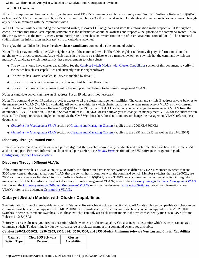
There may be a prompt for a login and password. Use the enable password as your login and password. In this example, mysecret is theenable password. After you enter the login and password, you see the Cisco access page, as you see in Figure 1. If you have trouble withswitch access when you use the web browser, refer to Troubleshooting Cisco Visual Switch Manager or Cluster Management Suite Accesson the Catalyst 2900 XL/3500 XL/2950/3550 Switch.
Figure 1
Note: Later software versions use a Cisco access page like this one:
Figure 2
Click Cluster Management Suite or Visual Switch Manager on the Cisco access page.
This brings up the Visual Switch Manager logo screen, as you see in Figure 3. The Switch Manager home page, as you see in Figure 4,loads.
Note: When you access the Cluster Management Suite or Visual Switch Manager link on the Cisco access page, you see the Visual SwitchManager logo screen first. With the enable of clustering, you see the Cluster Management Suite screen after the Visual Switch Managerlogo screen (instead of Figure 4).
Figure 3
6.
Cisco - Configuring and Analyzing Clustering on Catalyst Fixed Configuration Switches
http://www.cisco.com/warp/customer/473/61.html (11 of 41) [11/18/2004 10:44:08 AM]

Figure 4
Note: If you have difficulty with access to the Switch home page that you see in Figure 4, refer to Troubleshooting Cisco Visual SwitchManager or Cluster Management Suite Access on the Catalyst 2900 XL/3500 XL/2950/3550 Switch to troubleshoot the problem.
Up to this point, no cluster configuration has been done. Therefore, there are no changes in the configuration of any of the switches thatrelate to clustering. In the steps that follow, you add cluster commands in the configuration files. The procedure discusses each command.
From the menu bar, choose Cluster > Cluster Command Configuration.7.
Cisco - Configuring and Analyzing Clustering on Catalyst Fixed Configuration Switches
http://www.cisco.com/warp/customer/473/61.html (12 of 41) [11/18/2004 10:44:08 AM]

This brings up the Cluster Configuration window, as you see in Figure 5.
Figure 5
In the the Command Switch Status field, choose Enable.8.
Type a name in the Cluster Name field.
You can use up to 31 characters to name your cluster. This example uses "engineering" as the cluster name:
Figure 6
9.
Cisco - Configuring and Analyzing Clustering on Catalyst Fixed Configuration Switches
http://www.cisco.com/warp/customer/473/61.html (13 of 41) [11/18/2004 10:44:08 AM]

Click OK.
This enables clustering on the center switch and makes it a command switch. When you click OK, you see the addition of clusterinformation on the screen, as you see in Figure 7.
The Command IP Address and the Cluster Name are now visible. This screen also has the name Cluster Management Suite.
Figure 7
10.
Cisco - Configuring and Analyzing Clustering on Catalyst Fixed Configuration Switches
http://www.cisco.com/warp/customer/473/61.html (14 of 41) [11/18/2004 10:44:08 AM]

At this point, the update of the center switch (3524XL) configuration has occurred with the commands that appear in bold:
!hostname Switch!enable password mysecret!ip subnet-zerocluster enable engineering 0!!!interface VLAN1ip address 172.16.84.35 255.255.255.0no ip directed-broadcastip nat outside!!ip default-gateway 172.16.84.1ip Nat inside source list 199 interface VLAN1 overloadaccess-list 199 dynamic Cluster-NAT permit ip any any
!--- Full configuration output is suppressed.
When you issue the cluster enable engineering command, you enable command switch functionality with the cluster name of"engineering". Network Address Translation (NAT) commands have automatic addition to the configuration file of the command switch.Do not remove these commands because the commands access the member switches. When the command switch manages a member switchthrough the Web Interface, the command switch acts as a proxy and forwards HTTP and Java calls to the member switch. The commandswitch uses virtual inside NAT addresses (also known as CMP addresses) to perform this action. For details on how CMP works, see theCluster Management Protocol section of this document.
Choose Cluster > Cluster Management.
A new cluster management window opens. The window shows the Cluster Builder (map of the switches). Inside this window, the
11.
Cisco - Configuring and Analyzing Clustering on Catalyst Fixed Configuration Switches
http://www.cisco.com/warp/customer/473/61.html (15 of 41) [11/18/2004 10:44:08 AM]

Suggested Candidate window appears, as you see in Figure 8. You can move or minimize the Suggested Candidate window to see theCluster Builder window (map) clearly. The map shows the command and the candidate switch.
Cluster Builder uses CDP to discover candidate switches that are capable of addition to a cluster. With CDP, the command switch canautomatically discover switches in star or daisy-chain topologies that are up to three cluster-enabled devices (three hops) away from theedge of the cluster. (See Step 3 of this section.) With Cisco IOS Software Release 12.0(5)XU code, or later, you can configure thecommand switch to discover switches that are up to seven cluster-enabled devices (seven hops) away.
Note: In the Suggested Candidate window, the Show suggested candidates every time Cluster Builder starts check box is checked.Depending on this selection, you may or may not see the Suggested Candidate window, which is enabled by default.
Figure 8
Note: There is only one candidate switch that appears in the map. The command switch appears in green, and the candidate switch appearsin blue. The switches appear this way because there are two switches that have the default host name of Switch. At this time, none of thecandidate switches that appear in blue have been added in the cluster. The Cluster Manager only displayed one switch in the Figure 8topology diagram when there are actually two.
You can see the correct number of candidate switches in the Suggested Candidate window, as you see in Figure 8. You can also use the CLIto check the correct number of candidate switches that have the potential to be a member switch. For example:
Switch# show cluster candidates |---Upstream---|MAC Address Name Device Type PortIf FEC Hops SN PortIf FEC00e0.1e9f.50c0 Switch WS-C2916M-XL Fa0/1 1 0 Fa0/200d0.5868.eb80 Switch WS-C3512-XL Gi0/2 1 0 Gi0/1
Click OK in the Suggested Candidate window, and wait for about 30 seconds.
You see this screen, which shows the correct number of member switches and the command switch:
Figure 9
12.
Cisco - Configuring and Analyzing Clustering on Catalyst Fixed Configuration Switches
http://www.cisco.com/warp/customer/473/61.html (16 of 41) [11/18/2004 10:44:08 AM]

In this diagram, center switch Switch is the command switch. Switch-1 and Switch-2 are the member switches. Now, all the switches aregreen, which shows that they are in the cluster with the name "engineering".
You can verify this cluster if you issue these commands on the command and member switches:
Command Switch (center switch, 3524XL):
Switch# show clusterCommand switch for cluster "engineering" Total number of members: 3 Status: 0 members are unreachable Time since last status change: 0 days, 0 hours, 7 minutes Redundancy: Disabled Heartbeat interval: 8 Heartbeat hold-time: 80 Extended discovery hop count: 3
Switch# show cluster members |---Upstream---|SN MAC Address Name PortIf FEC Hops SN PortIf FEC State0 00d0.5868.f180 Switch 0 Up (Cmdr)1 00e0.1e9f.50c0 Switch-1 Fa0/1 1 0 Fa0/2 Up2 00d0.5868.eb80 Switch-2 Gi0/2 1 0 Gi0/1 Up
Switch# show cluster view |---Upstream---|SN MAC Address ow Name Device Type PortIf FEC Hops SN PortIf FEC0 00d0.5868.f180 Switch WS-C3524-XL 01 00e0.1e9f.50c0 Switch-1 WS-C2916M-XL Fa0/1 1 0 Fa0/22 00d0.5868.eb80 Switch-2 WS-C3512-XL Gi0/2 1 0 Gi0/1
The changes that take place in the configuration file of the command switch after you perform Step 12 appear here in bold:
!ip subnet-zero
❍
Cisco - Configuring and Analyzing Clustering on Catalyst Fixed Configuration Switches
http://www.cisco.com/warp/customer/473/61.html (17 of 41) [11/18/2004 10:44:08 AM]

cluster enable engineering 0cluster member 1 mac-address 00e0.1e9f.50c0cluster member 2 Mac-address 00d0.5868.eb80!!!
!--- Full configuration output is suppressed.
Note: When a candidate switch becomes a member switch, the command switch configuration adds the member switch MACaddress. Also, the member switch configuration adds the command switch MAC address.
Member Switch-1 (bottom switch, 2916MXL)
Switch-1# show clusterCluster member 1Cluster name: engineeringManagement ip address: 172.16.84.35Command device Mac address: 00d0.5868.f180Switch-1#
The management IP address is the IP address of the command switch. This defines the concept of clustering, which is themanagement of a group of switches with use of a single IP address.
Also, if you have console connection to member Switch-1, this message appears on the console of the member switch as soon as thecluster adds the switch:
Switch#%CMP-CLUSTER_MEMBER_1-5-ADD: The Device is added to the cluster(Cluster Name: engineering, CMDR IP Address 172.16.84.35)Switch-1#
The changes that take place in the configuration file of the command switch after you perform Step 12 appear here in bold:
!hostname Switch-1!enable password mysecret!!no spanning-tree vlan 1no ip domain-lookup!cluster commander-address 00d0.5868.f180
!--- You may also see the member number and cluster name in the!--- above line. This depends on the version of code that you use.
!interface VLAN1no ip addressno ip route-cache
!--- Full configuration output is suppressed.
❍
Member Switch-2 (top switch, 3512XL)
Switch-2# show clusterMember switch for cluster "engineering" Member number: 2 Management IP address: 172.16.84.35 Command switch Mac address: 00d0.5868.f180 Heartbeat interval: 8 Heartbeat hold-time: 80Switch-2#
❍
Cisco - Configuring and Analyzing Clustering on Catalyst Fixed Configuration Switches
http://www.cisco.com/warp/customer/473/61.html (18 of 41) [11/18/2004 10:44:08 AM]

The management IP address is the IP address of the command switch.
Also, if you have console connection to member Switch-2, this message appears on the console of the member switch as soon as thecluster adds the switch:
Switch#%CMP-CLUSTER_MEMBER_2-5-ADD: The Device is added to the cluster(Cluster Name: engineering, CMDR IP Address 172.16.84.35)Switch-2#
The changes that take place in the configuration file of the command switch after you perform Step 12 appear here in bold:
!hostname Switch-2!enable password mysecret!!ip subnet-zero!cluster commander-address 00d0.5868.f180 member 2 name engineering
!--- If you run an older version of code, you may not see!--- the member number and cluster name in the above line.
!interface VLAN1no ip addressno ip directed-broadcastno ip route-cache
!--- Full configuration output is suppressed.
If you view the outputs from member Switch-1 and member Switch-2 configurations, you notice the inheritance by the memberswitches of the enable password and the host name, appended with a number of the command switch.
If a host name was not assigned previously to the member switch (as in this example), the command switch appends a uniquemember number to the command switch host name; the command switch then assigns the number sequentially to the switch when theswitch joins the cluster. The number indicates the order in which the switch joined the cluster. In this example, the command switchhas the default host name Switch. The first member switch (WS-C2916MXL) takes the host name Switch-1. The second memberswitch (WS-C3512XL) takes the host name Switch-2.
Note: If the member switch already has a host name, the switch retains that host name when it joins the cluster. If the member switchleaves the cluster, the host name remains.
The member switch also inherits the command switch enable secret or enable password when the switch joins the cluster. It retainsthe password when it leaves the cluster as well. If you have not configured a command switch password, the member switch inheritsa null password.
Choose Views > Toggle labels to see more detailed cluster information.
The window displays this additional information:
MAC address of the member switches❍
IP address of the command switch❍
Port numbers and the type of links (Fast Ethernet or Gigabit Ethernet links)❍
Figure 10
13.
Cisco - Configuring and Analyzing Clustering on Catalyst Fixed Configuration Switches
http://www.cisco.com/warp/customer/473/61.html (19 of 41) [11/18/2004 10:44:08 AM]

To see an image of all the switches in the cluster, choose Cluster > Go to Cluster Manager.
The Cluster Manager appears. It displays a view of the switches in a cluster form:
Figure 11
You can use Cluster Manager to manage and configure changes within a cluster. You can use it to monitor and configure ports, change themanagement VLAN, and change the host name. Cluster management and how to perform different configuration tasks with ClusterManager are beyond the scope of this document, however. For these details, refer to the documents:
Changing the Management VLAN section of Creating and Managing Clusters (2900XL/3500XL)❍
Changing the Management VLAN section of Creating and Managing Clusters (2950, 2955, and 2940/2970)❍
14.
Add a Member in an Existing Cluster
This section describes how to add a member switch to a cluster that already exists. The example adds a Catalyst 2924MXL switch in the cluster,as you see in Figure 10.
Complete these steps to add another member in the cluster with CMS:
Connect the switch that you want to add to one of the ports on either the command or the member switch.1.
Cisco - Configuring and Analyzing Clustering on Catalyst Fixed Configuration Switches
http://www.cisco.com/warp/customer/473/61.html (20 of 41) [11/18/2004 10:44:08 AM]

In the Lab Scenarios section of this document, the new switch connects to the fastethernet 0/2 interface of the command switch. Be surethat the ports that connect the two switches belong to the same management VLAN or that the ports are trunk ports. Also in the LabScenarios, all the ports belong to VLAN1, which is the management VLAN by default.
Note: Access to all the cluster management facilities is through the command switch IP address. The command switch IP address alwaysbelongs to the management VLAN (VLAN1, by default). All switches within the switch cluster must have the same management VLAN asthe command switch. As of Cisco IOS Software Release 12.0(5)XP for the 2900XL and 3500XL switches, you can change the managementVLAN from the default of VLAN1. In addition, Cisco IOS Software Release 12.0(5)XU or later allows you to change the managementVLAN for the entire switch cluster. The change requires a single command via the CMS Web Interface. For details on how to change themanagement VLAN, refer to these documents:
Changing the Management VLAN section of Creating and Managing Clusters (2900XL/3500XL)❍
Changing the Management VLAN section of Creating and Managing Clusters (2950, 2955, and 2940/2970)❍
In your browser, choose Cluster > Cluster Management.
The action opens the Cluster Builder in a new browser window and displays this screen:
Figure 12
You can see that the Suggested Candidate window lists the new switch (2924MXL) as a candidate switch. Figure 12 also shows that there isa new switch, in blue. The new switch connects to the center switch (command switch). When this candidate switch becomes a member ofthe cluster, the color changes to green, and the switch is listed as Switch-3.
2.
To add the candidate switch to the cluster and update the network map, perform one of these steps:
Click OK in the Suggested Candidate window and wait for a few seconds.
This shows a network map update with the new switch, Switch-3.
❍
Or, click the candidate switch, as you see in Figure 13, and then choose Add to Cluster.❍
Figure 13
3.
Cisco - Configuring and Analyzing Clustering on Catalyst Fixed Configuration Switches
http://www.cisco.com/warp/customer/473/61.html (21 of 41) [11/18/2004 10:44:08 AM]

Figure 14
Choose Views > Toggle Labels to see more details on the network map.
Figure 154.
Cisco - Configuring and Analyzing Clustering on Catalyst Fixed Configuration Switches
http://www.cisco.com/warp/customer/473/61.html (22 of 41) [11/18/2004 10:44:08 AM]

If you want to verify this cluster, issue these commands on the command switch and new member switch, Switch-3:
Command Switch (center switch, 3524XL)
Switch# show clusterCommand switch for cluster "engineering" Total number of members: 4 Status: 0 members are unreachable Time since last status change: 0 days, 0 hours, 7 minutes Redundancy: Disabled Heartbeat interval: 8 Heartbeat hold-time: 80 Extended discovery hop count: 3
Switch# show cluster members |---Upstream---|SN MAC Address Name PortIf FEC Hops SN PortIf FEC State0 00d0.5868.f180 Switch 0 Up (Cmdr)1 00e0.1e9f.50c0 Switch-1 Fa0/1 1 0 Fa0/2 Up2 00d0.5868.eb80 Switch-2 Gi0/2 1 0 Gi0/1 Up3 00ee.1e9f.50c0 Switch-3 Fa0/1 1 0 Fa0/3 Up
Switch# show cluster view |---Upstream---|SN MAC Address Name Device Type PortIf FEC Hops SN PortIf FEC0 00d0.5868.f180 Switch WS-C3524-XL 0 1 00e0.1e9f.50c0 Switch-1 WS-C2916M-XL Fa0/1 1 0 Fa0/22 0d0.5868.eb80 Switch-2 WS-C3512-XL Gi0/2 1 0 Gi0/13 00ee.1e9f.50c0 Switch-3 WS-C2924M-XL Fa0/1 1 0 Fa0/3
The changes that take place in the configuration file of the command switch after you perform Step 4 appear here in bold:
!
❍
Cisco - Configuring and Analyzing Clustering on Catalyst Fixed Configuration Switches
http://www.cisco.com/warp/customer/473/61.html (23 of 41) [11/18/2004 10:44:08 AM]

ip subnet-zerocluster enable engineering 0cluster member 1 Mac-address 00e0.1e9f.50c0cluster member 2 Mac-address 00d0.5868.eb80cluster member 3 Mac-address 00ee.1e9f.50c0!!!
!--- Full configuration output is suppressed.
Note: When a candidate switch becomes a member switch, the command switch configuration adds the member switch MACaddress. Also, the member switch configuration adds the command switch MAC address.
Member Switch-3 (2924MXL)
Switch-3# show clusterMember switch for cluster "engineering" Member number: 3 Management IP address: 172.16.84.35 Command switch Mac address: 00d0.5868.f180 Heartbeat interval: 8 Heartbeat hold-time: 80Switch-3#
The management IP address is the IP address of the command switch.
The changes that take place in the configuration file of the command switch after you perform Step 4 appear here in bold:
!hostname Switch-3!enable password mysecret!!ip subnet-zero!cluster commander-address 00d0.5868.f180 member 3 name engineering!interface VLAN1no ip addressno ip directed-broadcastno ip route-cache
!--- Full configuration output is suppressed.
❍
Choose Cluster > Go to Cluster Manager.
Cluster Manager appears, as you see in Figure 16. This view is updated from Figure 11 and shows the newly added switch (2924MXL) inthe list:
Figure 16
5.
Cisco - Configuring and Analyzing Clustering on Catalyst Fixed Configuration Switches
http://www.cisco.com/warp/customer/473/61.html (24 of 41) [11/18/2004 10:44:08 AM]

debug and show Commandsshow cluster●
show cluster members●
show cdp neighbors●
show cdp neighbors detail●
debug cluster member●
debug cluster neighbors●
debug cluster events●
debug cluster ip●
Sample show Command Output
show cluster and show cluster members
Use the show cluster and show cluster members commands to check the status of the cluster and the members.
Command Switch (center switch, 3524XL)
Switch# show clusterCommand switch for cluster "engineering" Total number of members: 4 Status: 0 members are unreachable Time since last status change: 0 days, 0 hours, 7 minutes Redundancy: Disabled Heartbeat interval: 8 Heartbeat hold-time: 80 Extended discovery hop count: 3
Switch# show cluster members |---Upstream---|SN MAC Address Name PortIf FEC Hops SN PortIf FEC State0 00d0.5868.f180 Switch 0 Up (Cmdr)1 00e0.1e9f.50c0 Switch-1 Fa0/1 1 0 Fa0/2 Up 2 00d0.5868.eb80 Switch-2 Gi0/2 1 0 Gi0/1 Up3 00ee.1e9f.50c0 Switch-3 Fa0/1 1 0 Fa0/3 Up
●
Cisco - Configuring and Analyzing Clustering on Catalyst Fixed Configuration Switches
http://www.cisco.com/warp/customer/473/61.html (25 of 41) [11/18/2004 10:44:08 AM]

If one of the member switches loses connectivity to the command switch, the output of the show cluster and show cluster memberscommands reflects the loss.
For example, if member Switch-2 loses connectivity to the command switch, the output of these commands is:
Switch# show cluster Command switch for cluster "engineering" Total number of members: 4 Status: 1 members are unreachable Time since last status change: 0 days, 0 hours, 0 minutes Redundancy: Disabled Heartbeat interval: 8 Heartbeat hold-time: 80 Extended discovery hop count: 3Switch#
Switch# show cluster member |---Upstream---|SN MAC Address Name PortIf FEC Hops SN PortIf FEC State0 00d0.5868.f180 Switch 0 Up (Cmdr)1 00e0.1e9f.50c0 Switch-1 Fa0/1 1 0 Fa0/2 Up 2 00d0.5868.eb80 Switch-2 1 Down3 00ee.1e9f.50c0 Switch-3 Fa0/1 1 0 Fa0/3 Up
Note: You do not see immediately the changes reflected by these commands. The command switch has to wait a certain interval(Heartbeat hold-time) before the command switch declares a member switch down. By default, heartbeat holdtime is 80 seconds.This is a configurable parameter. You can change the parameter if you issue the cluster holdtime 1-300 command in global configurationmode.
Member Switch-1 (2916MXL)
Switch-1# show clusterCluster member 1Cluster name: engineeringManagement ip address: 172.16.84.35Command device Mac address: 00d0.5868.f180Switch-1#
●
Member Switch-2 (top switch, 3512XL)
Switch-2# show cluster Member switch for cluster "engineering" Member number: 2 Management IP address: 172.16.84.35 Command switch Mac address: 00d0.5868.f180 Heartbeat interval: 8 Heartbeat hold-time: 80Switch-2#
●
Member Switch-3 (2924MXL)
Switch-3# show clusterMember switch for cluster "engineering" Member number: 3 Management IP address: 172.16.84.35 Command switch Mac address: 00d0.5868.f180 Heartbeat interval: 8 Heartbeat hold-time: 80Switch-3#
●
show cdp neighbors and show cdp neighbors detail
As discussed in the Candidate Switch and Member Switch Characteristics section of this document, all the switches, including the commandswitch, use CDPv2 to discover the CDP neighbors. The switches store this information in the respective CDP neighbor cache. When the commandswitch receives the information, the switch filters the CDP neighbor caches and creates a list of candidate switches.
Cisco - Configuring and Analyzing Clustering on Catalyst Fixed Configuration Switches
http://www.cisco.com/warp/customer/473/61.html (26 of 41) [11/18/2004 10:44:08 AM]
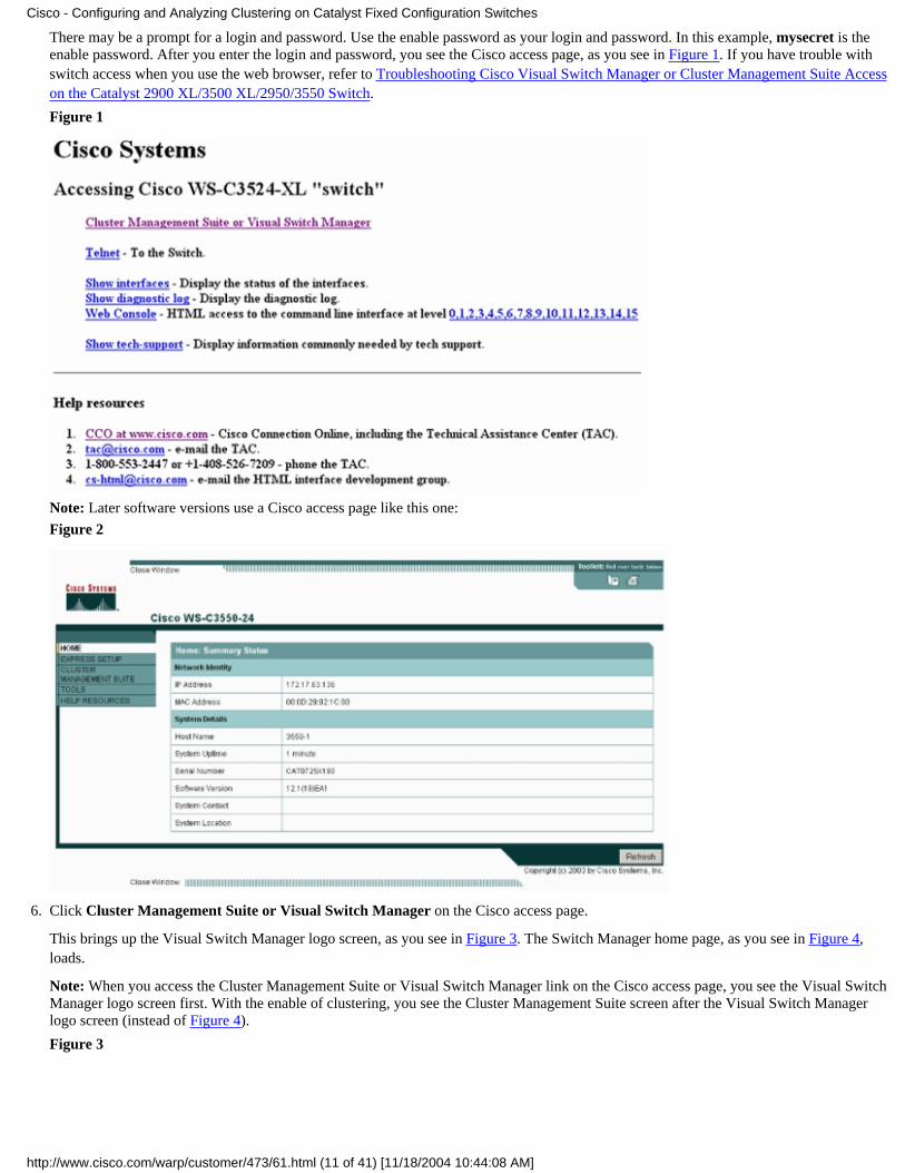
Use the show cdp neighbors and show cdp neighbors detail commands to verify that the switches are in the CDP neighbor cache and that all theswitches currently run CDPv2.
Command Switch (3524XL)
Switch# show cdp neighborsCapability Codes: R - Router, T - Trans Bridge, B - Source Route Bridge S - Switch, H - Host, I - IGMP, r - Repeater
Device ID Local Intrfce Holdtme Capability Platform Port IDSwitch-3 Fas 0/3 162 T S WS-C2924M-Fas 0/1Switch-2 Gig 0/1 121 T S WS-C3512-XGig 0/2Switch-1 Fas 0/2 136 S WS-C2916M-Fas 0/1
Switch# show cdp neighbors detail-------------------------Device ID: Switch-3Entry address(es):Platform: cisco WS-C2924M-XL, Capabilities: Trans-Bridge SwitchInterface: FastEthernet0/3, Port ID (outgoing port): FastEthernet0/1Holdtime : 132 sec
!--- Output suppressed.
advertisement version: 2Protocol Hello: OUI=0x00000C, Protocol ID=0x0112; payload len=25,value=0AA050C000000003010103FF00D05868F18000EE1E9F50C001VTP Management Domain: ''
-------------------------Device ID: Switch-2Entry address(Es): IP address: 0.0.0.0 IP address: 172.16.84.35Platform: cisco WS-C3512-XL, Capabilities: Trans-Bridge SwitchInterface: GigabitEthernet0/1, Port ID (outgoing port): GigabitEthernet0/2Holdtime : 141 sec
!--- Output suppressed.
advertisement version: 2Protocol Hello: OUI=0x00000C, Protocol ID=0x0112; payload Len=27,value=0A68EB8000000002010123FF00D05868F18000D05868EB80010001VTP Management Domain: ''Duplex: full
-------------------------Device ID: Switch-1Entry address(Es): IP address: 172.16.84.35Platform: cisco WS-C2916M-XL, Capabilities: SwitchInterface: FastEthernet0/2, Port ID (outgoing port): FastEthernet0/1Holdtime : 140 sec
!--- Output suppressed.
advertisement version: 2Protocol Hello: OUI=0x00000C, Protocol ID=0x0112; payload Len=25,value=0A9F50C000000001010103FF00D05868F18000E01E9F50C001VTP Management Domain: ''
●
Cisco - Configuring and Analyzing Clustering on Catalyst Fixed Configuration Switches
http://www.cisco.com/warp/customer/473/61.html (27 of 41) [11/18/2004 10:44:08 AM]

Member Switch-1 (2916MXL)
Switch-1# show cdp neighbors Capability Codes: R - Router, T - Trans Bridge, B - Source Route Bridge S - Switch, H - Host, I - IGMP, r - Repeater
Device ID Local Intrfce Holdtme Capability Platform Port IDSwitch Fas 0/1 139 T S WS-C3524-XFas 0/2
Switch-1# show cdp neighbors detail-------------------------Device ID: SwitchEntry address(Es): IP address: 172.16.84.35 IP address: 172.16.84.35Platform: cisco WS-C3524-XL, Capabilities: Trans-Bridge SwitchInterface: FastEthernet0/1, Port ID (outgoing port): FastEthernet0/2Holdtime : 147 sec
!--- Output suppressed.
advertisement version: 2Protocol Hello: OUI=0x00000C, Protocol ID=0x0112; payload Len=27,value=0A68F18000000000010123FF00D05868F18000D05868F180000001VTP Management Domain: ''
●
Member Switch-2 (3512XL)
Switch-2# show cdp neighbors Capability Codes: R - Router, T - Trans Bridge, B - Source Route Bridge S - Switch, H - Host, I - IGMP, r - Repeater
Device ID Local Intrfce Holdtme Capability Platform Port IDSwitch Gig 0/2 147 T S WS-C3524-XGig 0/1
Switch-2# show cdp neighbors detail-------------------------Device ID: SwitchEntry address(Es): IP address: 172.16.84.35 IP address: 172.16.84.35Platform: cisco WS-C3524-XL, Capabilities: Trans-Bridge SwitchInterface: GigabitEthernet0/2, Port ID (outgoing port): GigabitEthernet0/1Holdtime : 141 sec
!--- Output suppressed.
advertisement version: 2 Protocol Hello: OUI=0x00000C, Protocol ID=0x0112; payload Len=27, value=0A68F18000000000010123FF00D05868F18000D05868F180000001 VTP Management Domain: '' Duplex: full
●
Member Switch-3 (2924MXL)
Switch-3# show cdp neighbors Capability Codes: R - Router, T - Trans Bridge, B - Source Route Bridge S - Switch, H - Host, I - IGMP, r - Repeater
Device ID Local Intrfce Holdtme Capability Platform Port IDSwitch Fas 0/1 125 T S WS-C3524-XFas 0/3
Switch-3# show cdp neighbors detail
●
Cisco - Configuring and Analyzing Clustering on Catalyst Fixed Configuration Switches
http://www.cisco.com/warp/customer/473/61.html (28 of 41) [11/18/2004 10:44:08 AM]

-------------------------Device ID: SwitchEntry address(Es): IP address: 172.16.84.35 IP address: 172.16.84.35Platform: cisco WS-C3524-XL, Capabilities: Trans-Bridge SwitchInterface: FastEthernet0/1, Port ID (outgoing port): FastEthernet0/3Holdtime : 179 sec
!--- Output suppressed.
advertisement version: 2Protocol Hello: OUI=0x00000C, Protocol ID=0x0112; payload Len=27,value=0A68F18000000000010123FF00D05868F18000D05868F180000001VTP Management Domain: ''
Note: If you do not see advertisement version: 2 in the show cdp neighbors detail command output for a switch, that switch cannotbecome a member switch.
Sample debug Command Output
This section discusses the debug commands that verify the cluster activity. Here, the commands verify the cluster activity between the commandswitch (3524XL) and member Switch-2 (3512XL). You can use the same debug commands to verify the cluster activity between the commandswitch and any of the member switches.
Note: Whenever there is an addition or removal of a member with use of the Web Interface, you see the log of this information:
%CMP-CLUSTER_MEMBER_2-5-REMOVE:The Device is removed from the cluster (Cluster Name: engineering)
%CMP-CLUSTER_MEMBER_2-5-ADD:The Device is added to the cluster(Cluster Name: engineering, CMDR IP Address172.16.84.35)
debug cluster member, debug cluster neighbors, and debug cluster events
The first two debug commands in these examples, debug cluster member and debug cluster neighbors, show the outgoing cluster neighborupdates from a command switch or a member switch. The third debug command, debug cluster events, shows incoming neighbor hellos.Between the commands, comments in blue enhance the visibility of certain outputs. Also, this display suppresses unnecessary information fromthe complete debug output.
Command Switch (3524XL)
Switch# debug cluster members Cluster members debugging is onSwitch#23:21:47: Sending neighbor update...23:21:47: Cluster Member: 00, active.
!--- Member 00 means commander switch.
23:21:47: Unanswered heartbeats: 123:21:47: Hops to commander: 023:21:47: Assigned CMP address: 10.104.241.128
!--- This is the commander CMP address.
23:21:47: Cmdr IP address: 172.16.84.35 23:21:47: Cmdr CMP address: 10.104.241.128
!--- This is the commander CMP address.
23:21:47: Auto update counter: 0
●
Cisco - Configuring and Analyzing Clustering on Catalyst Fixed Configuration Switches
http://www.cisco.com/warp/customer/473/61.html (29 of 41) [11/18/2004 10:44:08 AM]

23:21:47: Cmdr MAC address: 00d0.5868.f18023:21:47: Mbr MAC address: 00d0.5868.f18023:21:47: Command Port ID: 23:21:47: Platform Name: cisco WS-C3524-XL23:21:47: Host Name: Switch
Switch# debug cluster neighborsCluster neighbors debugging is onSwitch#23:51:50: Neighbor update from member 0
!--- This is an update from the commander.
23:51:50: 3 Cluster neighbors:
!--- Information about member Switch-2 starts here.
23:51:50: 00d0.5868.eb80 connected to Member 0 on port GigabitEthernet0/223:51:50: Port Macaddr: 00d0.5868.eb8e23:51:50: Hostname: Switch-223:51:50: Port ID: GigabitEthernet0/223:51:50: Neighbor FEC: 25523:51:50: Member FEC: 25523:51:50: Capabilities: 0A23:51:50: Link Qualification: 023:51:50: Qualification Note: 2123:51:50: Member 2 of stack with commander 0.104.187.14023:51:50: CMP address: 10.104.235.12823:51:50: Hops to Commander: 123:51:50: Management vlan: 1
!--- Information about member Switch-2 ends here.
!--- Information about member Switch-1 starts here.
23:51:50: 00e0.1e9f.50c0 connected to Member 0 on port FastEthernet0/223:51:50: Port Macaddr: 00e0.1e9f.50c123:51:50: Hostname: Switch-123:51:50: Port ID: FastEthernet0/123:51:50: Neighbor FEC: 25523:51:50: Member FEC: 25523:51:50: Capabilities: 0823:51:50: Link Qualification: 323:51:50: Qualification Note: 0123:51:50: Member 1 of stack with commander 0.77.44.12423:51:50: CMP address: 10.159.80.19223:51:50: Hops to Commander: 123:51:50: Management vlan: 0
!--- Information about member Switch-1 ends here.
!--- Information about member Switch-3 starts here.
23:51:50: 00ee.1e9f.50c0 connected to Member 0 on port FastEthernet0/323:51:50: Port Macaddr: 00ee.1e9f.50c123:51:50: Hostname: Switch-323:51:50: Port ID: FastEthernet0/123:51:50: Neighbor FEC: 25523:51:50: Member FEC: 255
Cisco - Configuring and Analyzing Clustering on Catalyst Fixed Configuration Switches
http://www.cisco.com/warp/customer/473/61.html (30 of 41) [11/18/2004 10:44:08 AM]

23:51:50: Capabilities: 0A23:51:50: Link Qualification: 323:51:50: Qualification Note: 0023:51:50: Member 3 of stack with commander 0.77.184.5623:51:50: CMP address: 10.160.80.19223:51:50: Hops to Commander: 123:51:50: Management vlan: 1
!--- Information about member Switch-3 ends here.
!--- The information that follows is from Switch-2, as seen on !--- the command switch.!--- You can see the same information if you issue the!--- debug cluster events command on certain versions !--- of codes.
Cluster neighbor's Protocol Hello payload:23:52:00: Sender Version: 1, Works with version 1 and later23:52:00: Flags: 23, Number of hops to the commander: 123:52:00: Cluster member number: 223:52:00: Cluster Cmdr Mac Address: 00d0.5868.f18023:52:00: Sender Mac address: 00d0.5868.eb80
!--- This is the Switch-2 MAC address.
23:52:00: Sender CMP address: 10.104.235.128
!--- This is the Switch-2 CMP address.
23:52:00: Upstream switch No: 0.0.0.023:52:00: FEC Number: 25523:52:00: Management vlan: 1
!--- Output suppressed.
Member Switch-2 (3512XL)
Switch-2# debug cluster memberCluster members debugging is onSwitch-2#23:22:51: Sending neighbor update...23:22:51: Switch 00d0.5868.f180 connected on port GigabitEthernet0/2
!--- This is the command switch MAC address local port.
23:22:51: Port ID: GigabitEthernet0/223:22:51: Capabilities: 0A23:22:51: Link Qualification: 523:22:51: Qualification Note: 2023:22:51: Member 0 of stack with commander 00d0.5868.f18023:22:51: CMP address: 10.104.241.128
!--- This is the commander CMP address.
23:22:51: Hops to Commander: 023:22:51: Management vlan: 1*23:22:51:
!--- Up to this point, the information is about the command switch.!--- The output that follows is the local switch information that goes to the !--- neighbor (command) switch.
●
Cisco - Configuring and Analyzing Clustering on Catalyst Fixed Configuration Switches
http://www.cisco.com/warp/customer/473/61.html (31 of 41) [11/18/2004 10:44:08 AM]

Cluster Member: 02, active.23:22:51: Unanswered heartbeats: 123:22:51: Hops to commander: 123:22:51: Assigned CMP address: 10.104.235.12823:22:51: Cmdr IP address: 172.16.84.3523:22:51: Cmdr CMP address: 10.104.241.12823:22:51: Auto update counter: 023:22:51: Cmdr MAC address: 00d0.5868.f18023:22:51: Mbr MAC address: 00d0.5868.eb8023:22:51: Command Port ID: GigabitEthernet0/2
!--- This is the port that connects to the commander.
23:22:51: Platform Name: cisco WS-C3512-XL23:22:51: Host Name: Switch-2Switch-2#
Switch-2# debug cluster neighborsCluster neighbors debugging is onSwitch-2#23:59:32: cmi_setCommandPort: setting ups mbr num to 023:59:32: cmp_sendNeighborsToCmdr: skip neighbor 00d0.5868.f180Switch-2#23:59:42:
!--- Information that follows is from the command switch.!--- You can see the same information if you issue the!--- debug cluster events command on certain versions !--- of codes.
Cluster neighbor's Protocol Hello payload:23:59:42: Sender Version: 1, Works with version 1 and later23:59:42: Flags: 23, Number of hops to the commander: 023:59:42: Cluster member number: 023:59:42: Cluster Cmdr Mac Address: 00d0.5868.f18023:59:42: Sender Mac address: 00d0.5868.f180
!--- This is the commander MAC address.
23:59:42: Sender CMP Address: 10.104.241.128
!--- This is the commander CMP address.
23:59:42: Upstream switch No: 0.0.0.023:59:42: FEC Number: 25523:59:42: Management vlan: 1
debug cluster ip
A CMP Address field appears in the debug command output. As the Cluster Management Protocol section explains, the commander andmember switches communicate with use of these CMP addresses.
If you view the outputs in the debug cluster member, debug cluster neighbors, and debug cluster events section, you can see that the CMPaddresses of the switches in this example are:
Commander CMP address: 10.104.241.128●
Member Switch-1 CMP address: 10.159.80.192●
Member Switch-2 CMP address: 10.104.235.128●
Member Switch-3 CMP address: 10.160.80.192●
As the Cluster Management Protocol section discusses, CMP consists of three key technology pieces. One of them is the CMP/RARP mechanism.
Cisco - Configuring and Analyzing Clustering on Catalyst Fixed Configuration Switches
http://www.cisco.com/warp/customer/473/61.html (32 of 41) [11/18/2004 10:44:08 AM]

CMP/RARP also adds and removes switches from the cluster. The debug output below shows the log of CMP/RARP messages at the addition ofa member to the cluster.
Note: To be consistent with the commands in the debug cluster member, debug cluster neighbors, and debug cluster events section, here youissue the debug cluster ip command on the commander (3524XL) and the second switch to add (Switch-2, 3512XL).
Commander Switch (3524XL) (the addition of member Switch-2)
Switch# debug cluster ipCluster IP/transport debugging is onSwitch#
!--- The command switch generates the new CMP address.
1d08h: cmdr_generate_cluster_ip_address: generated cluster,ip addr 10.104.235.128 for Mac 00d0.5868.eb80
!--- The commander allocates the CMP address to member Switch-2.
1d08h: cmdr_generate_and_assign_ip_address:setting addr for member 2 addr 10.104.235.128
1d08h: cmdr_generate_and_assign_ip_address:adding static ARP for 10.104.235.1281d08h: cluster_send_rarp_reply:Sending reply out on Virtual1 to member 21d08h: cmdr_process_rarp_request: received RARP req :1d08h: proto type : 00001d08h: source Mac : 00d0.5868.eb80
!--- This is the member MAC Address.
1d08h: source ip : 10.104.235.128
!--- This is the member CMP Address.
1d08h: target Mac : 00d0.5868.f180
!--- This is the commander MAC Address.
1d08h: target ip : 10.104.241.128
!--- This is the commander CMP Address.
1d08h: cmdr_process_rarp_request: rcvd ACK for the bootstrap req
●
Member Switch-2 (3512XL) (which the commander adds)
Switch# debug cluster ipCluster IP/transport debugging is onSwitch#
!--- The member switch receives information from the command switch.
00:01:24: cluster_process_rarp_reply: received RARP reply :00:01:24: source Mac : 00d0.5868.f180
!--- This is the commander MAC Address.
00:01:24: source ip : 10.104.241.128
!--- This is the commander CMP Address.
●
Cisco - Configuring and Analyzing Clustering on Catalyst Fixed Configuration Switches
http://www.cisco.com/warp/customer/473/61.html (33 of 41) [11/18/2004 10:44:08 AM]

00:01:24: target Mac : 00d0.5868.eb80
!--- This is the member MAC Address.
00:01:24: target ip : 10.104.235.128
!--- This is the member CMP Address.!--- The member switch extracts and implements the cluster information.
00:01:24: cluster_process_rarp_reply:setting commander's MAC address: 00d0.5868.f18000:01:24: create_cluster_idb: creating HWIDB(0x0) for the cluster00:01:24: cluster_create_member_idb:creating cluster-idb 4D4378, cmp-addr: 10.104.235.12800:01:24: Authorizing the password string:00:01:24: cluster_send_rarp_request: Sending request out to cmdr00:01:24: cluster_process_rarp_reply:created hwidb and set IP address (10.104.235.128)00:01:24: cluster_process_rarp_reply:setting commander's addr (10.104.241.128) info00:01:24: cluster_process_rarp_reply:setting static ARP for cmdr addr 10.104.241.12800:01:24: cluster_set_default_gateway:setting default gw to cmdr's addr (10.104.241.128)00:01:24: setting hostname to Switch-200:01:24: setting password to enable password 0 mysecret00:01:24: cluster_pick_defaultidb: picking cluster IDB to be default IDB00:01:24: This switch is added to the cluster00:01:24: Cluster Name : engineering ; Cmdr IP address: 172.16.84.3500:01:24: CMP address: 10.104.235.128 ; Cmdr CMP address: 10.104.241.128
!--- At this point, the switch has been added to the cluster.
00:01:24: %CMP-CLUSTER_MEMBER_2-5-ADD: The Device is added to the cluster(Cluster Name: engineering, CMDR IP Address 172.16.84.35)00:01:24: cluster_process_rarp_reply: bootstrap for the firsttime, start member00:01:24: cluster_process_rarp_reply: setting netsareup to TRUE
Use of rcommand for Remote CLI Administration
This last portion of the debug analysis explains how CMP/IP works. As the Cluster Management Protocol section of this document discusses,CMP/IP is the transport mechanism to exchange management packets between the command switch and member switches.
One example is the use of rcommand, which is actually a Telnet session from the command switch to the member switch. It uses the same virtualCMP addresses.
Establish a Telnet session to the command switch.1.
From the CLI on the command switch, issue rcommand to get to the CLI of any of the member switches.
The rcommand is helpful in situations in which you want to troubleshoot or make configuration changes on any of the member switcheswith use of the CLI.
This example demonstrates usage:
Switch# rcommand 2
!--- This accesses member Switch-2.
Trying ... Open
Switch-2#
!--- Here, you establish a Telnet session with member Switch-2.
Switch-2# exit
2.
Cisco - Configuring and Analyzing Clustering on Catalyst Fixed Configuration Switches
http://www.cisco.com/warp/customer/473/61.html (34 of 41) [11/18/2004 10:44:08 AM]
!--- Use this command to end the Telnet session.
[Connection closed by foreign host]Switch#
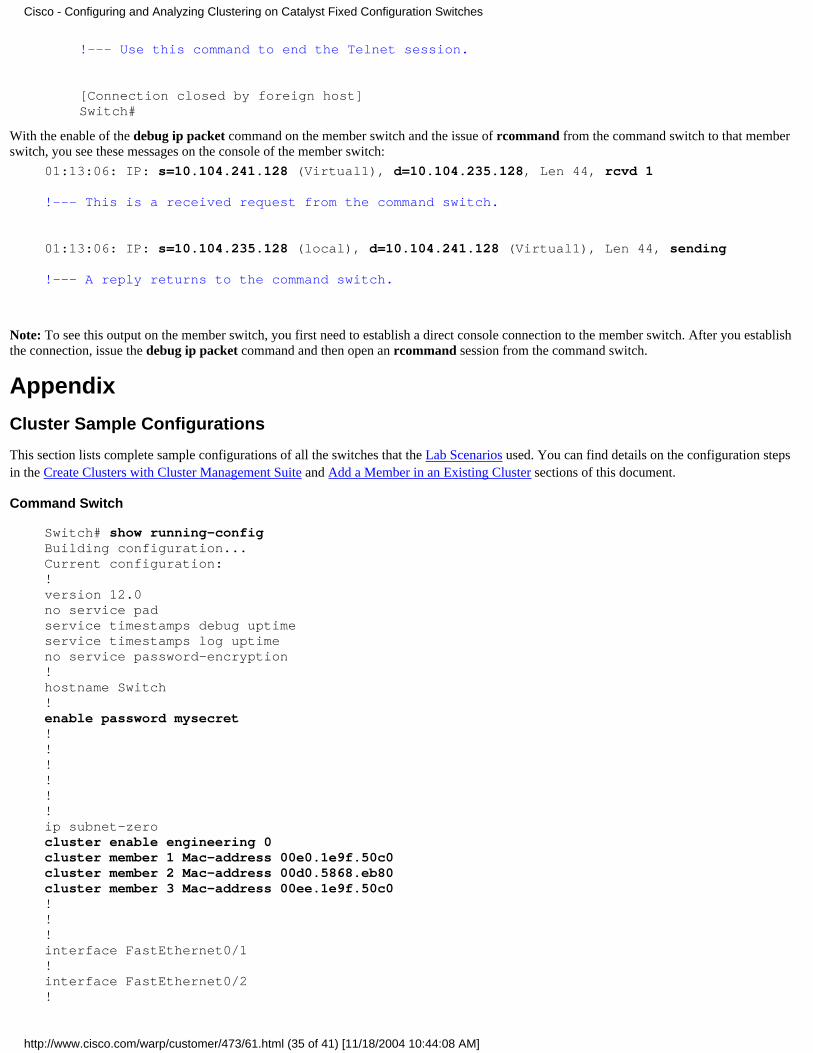
With the enable of the debug ip packet command on the member switch and the issue of rcommand from the command switch to that memberswitch, you see these messages on the console of the member switch:
01:13:06: IP: s=10.104.241.128 (Virtual1), d=10.104.235.128, Len 44, rcvd 1
!--- This is a received request from the command switch.
01:13:06: IP: s=10.104.235.128 (local), d=10.104.241.128 (Virtual1), Len 44, sending
!--- A reply returns to the command switch.
Note: To see this output on the member switch, you first need to establish a direct console connection to the member switch. After you establishthe connection, issue the debug ip packet command and then open an rcommand session from the command switch.
Appendix
Cluster Sample Configurations
This section lists complete sample configurations of all the switches that the Lab Scenarios used. You can find details on the configuration stepsin the Create Clusters with Cluster Management Suite and Add a Member in an Existing Cluster sections of this document.
Command Switch
Switch# show running-configBuilding configuration...Current configuration:!version 12.0no service padservice timestamps debug uptimeservice timestamps log uptimeno service password-encryption!hostname Switch!enable password mysecret!!!!!!ip subnet-zerocluster enable engineering 0cluster member 1 Mac-address 00e0.1e9f.50c0cluster member 2 Mac-address 00d0.5868.eb80cluster member 3 Mac-address 00ee.1e9f.50c0!!!interface FastEthernet0/1!interface FastEthernet0/2!
Cisco - Configuring and Analyzing Clustering on Catalyst Fixed Configuration Switches
http://www.cisco.com/warp/customer/473/61.html (35 of 41) [11/18/2004 10:44:08 AM]

interface FastEthernet0/3!interface FastEthernet0/4!interface FastEthernet0/5!interface FastEthernet0/6!interface FastEthernet0/7!interface FastEthernet0/8!interface FastEthernet0/9!interface FastEthernet0/10!interface FastEthernet0/11!interface FastEthernet0/12!interface FastEthernet0/13!interface FastEthernet0/14!interface FastEthernet0/15!interface FastEthernet0/16!interface FastEthernet0/17!interface FastEthernet0/18!interface FastEthernet0/19!interface FastEthernet0/20!interface FastEthernet0/21!interface FastEthernet0/22!interface FastEthernet0/23!interface FastEthernet0/24!interface GigabitEthernet0/1!interface GigabitEthernet0/2!interface VLAN1ip address 172.16.84.35 255.255.255.0no ip directed-broadcastip Nat outside!ip default-gateway 172.16.84.1ip Nat inside source list 199 interface VLAN1 overloadaccess-list 199 dynamic Cluster-NAT permit ip any any!line con 0transport input nonestopbits 1line vty 0 4loginline vty 5 15
Cisco - Configuring and Analyzing Clustering on Catalyst Fixed Configuration Switches
http://www.cisco.com/warp/customer/473/61.html (36 of 41) [11/18/2004 10:44:08 AM]

login!end
Member Switch-1
Switch-1# show running-configBuilding configuration...Current configuration:!version 11.2no service padno service udp-small-serversno service tcp-small-servers!hostname Switch-1!enable password mysecret!!no spanning-tree vlan 1no ip domain-lookup!cluster commander-address 00d0.5868.f180!interface VLAN1no ip addressno ip route-cache!interface FastEthernet0/1!interface FastEthernet0/2!interface FastEthernet0/3!interface FastEthernet0/4!interface FastEthernet0/5!interface FastEthernet0/6!interface FastEthernet0/7!interface FastEthernet0/8!interface FastEthernet0/9!interface FastEthernet0/10!interface FastEthernet0/11!interface FastEthernet0/12!interface FastEthernet0/13!interface FastEthernet0/14!interface FastEthernet0/15!interface FastEthernet0/16!!line con 0stopbits 1
Cisco - Configuring and Analyzing Clustering on Catalyst Fixed Configuration Switches
http://www.cisco.com/warp/customer/473/61.html (37 of 41) [11/18/2004 10:44:08 AM]

line vty 0 4loginline vty 5 15login!end
Member Switch-2
Switch-2# show running-configBuilding configuration...Current configuration:!version 12.0no service padservice timestamps debug uptimeservice timestamps log uptimeno service password-encryption!hostname Switch-2!enable password mysecret!!!!!!ip subnet-zero!cluster commander-address 00d0.5868.f180 member 2 name engineering!!interface FastEthernet0/1!interface FastEthernet0/2!interface FastEthernet0/3!interface FastEthernet0/4!interface FastEthernet0/5!interface FastEthernet0/6!interface FastEthernet0/7!interface FastEthernet0/8!interface FastEthernet0/9!interface FastEthernet0/10!interface FastEthernet0/11!interface FastEthernet0/12!interface GigabitEthernet0/1!interface GigabitEthernet0/2!interface VLAN1no ip address
Cisco - Configuring and Analyzing Clustering on Catalyst Fixed Configuration Switches
http://www.cisco.com/warp/customer/473/61.html (38 of 41) [11/18/2004 10:44:08 AM]

no ip directed-broadcastno ip route-cache!!line con 0transport input nonestopbits 1line vty 0 4loginline vty 5 15login!end
Member Switch-3
Switch-3# show running-configBuilding configuration...Current configuration:!version 12.0no service padservice timestamps debug uptimeservice timestamps log uptimeno service password-encryption!hostname Switch-3!enable password mysecret!!!!!!ip subnet-zero!cluster commander-address 00d0.5868.f180 member 3 name engineering!!interface FastEthernet0/1!interface FastEthernet0/2!interface FastEthernet0/3!interface FastEthernet0/4!interface FastEthernet0/5!interface FastEthernet0/6!interface FastEthernet0/7!interface FastEthernet0/8!interface FastEthernet0/9!interface FastEthernet0/10!interface FastEthernet0/11!interface FastEthernet0/12!
Cisco - Configuring and Analyzing Clustering on Catalyst Fixed Configuration Switches
http://www.cisco.com/warp/customer/473/61.html (39 of 41) [11/18/2004 10:44:08 AM]

interface FastEthernet0/13!interface FastEthernet0/14!interface FastEthernet0/15!interface FastEthernet0/16!interface FastEthernet0/17!interface FastEthernet0/18!interface FastEthernet0/19!interface FastEthernet0/20!interface FastEthernet0/21!interface FastEthernet0/22!interface FastEthernet0/23!interface FastEthernet0/24!interface GigabitEthernet1/1!interface VLAN1no ip directed-broadcastno ip route-cache!!!line con 0transport input nonestopbits 1line vty 5 15!end
Additional Information
For information on how to use CMS after initial configuration, refer to the software configuration guide for your switch product:
Getting Started with CMS on 2940 Series Switches●
Getting Started with CMS on 2950 Series Switches●
Getting Started with CMS on 2970 Series Switches●
Getting Started with CMS on 3550 Series Switches●
Getting Started with CMS on 3750 Series Switches●
NetPro Discussion Forums - Featured ConversationsNetworking Professionals Connection is a forum for networking professionals to share questions, suggestions, and information about networkingsolutions, products, and technologies. The featured links are some of the most recent conversations available in this technology.
NetPro Discussion Forums - Featured Conversations for LANNetwork Infrastructure: LAN Routing and Switching
Network Infrastructure: Getting Started with LANs
Cisco - Configuring and Analyzing Clustering on Catalyst Fixed Configuration Switches
http://www.cisco.com/warp/customer/473/61.html (40 of 41) [11/18/2004 10:44:08 AM]

Related InformationCisco IOS Desktop Switching Software Configuration Guide, Release 12.0(5)XU●
Catalyst 2950 and Catalyst 2955 Switch Software Configuration Guide, 12.1(20)EA2●
Clustering Switches 2940 Configuration Guide●
Clustering Switches 3550 Configuration Guide●
Clustering Switches 3750 Configuration Guide●
Troubleshooting Cisco Visual Switch Manager or Cluster Management Suite Access on the Catalyst 2900 XL/3500 XL/2950/3550Switch
●
LAN Product Support Pages●
LAN Switching Support Page●
Technical Support - Cisco Systems●
All contents are Copyright © 1992-2004 Cisco Systems, Inc. All rights reserved. Important Notices and Privacy Statement.
Updated: Nov 17, 2004 Document ID: 4085
Cisco - Configuring and Analyzing Clustering on Catalyst Fixed Configuration Switches
http://www.cisco.com/warp/customer/473/61.html (41 of 41) [11/18/2004 10:44:08 AM]

![Catalyst 2960 and 2960-S Software Configuration Guide, 12.2(53)SE1 - Configuring EtherChannels and Link-State Tracking [Cisco Catalyst 2960 Series Switches] - Cisco](https://static.fdocuments.us/doc/165x107/577c80a31a28abe054a99054/catalyst-2960-and-2960-s-software-configuration-guide-12253se1-configuring.jpg)