VRF-Lite for Ethernet Routing Switch 8600 / 8800 Technical ...

Configuring VRF-lite
• Information About VRF-lite, on page 1• Guidelines for Configuring VRF-lite, on page 3• How to Configure VRF-lite, on page 4• Configuring VRF-lite for IPv6, on page 12• Additional Information for VRF-lite, on page 23• Verifying VRF-lite Configuration, on page 23• Configuration Examples for VRF-lite, on page 26• Feature History and Information for Multicast VRF-lite, on page 33
Information About VRF-liteVRF-lite is a feature that enables a service provider to support two or more VPNs, where IP addresses can beoverlapped among the VPNs. VRF-lite uses input interfaces to distinguish routes for different VPNs and formsvirtual packet-forwarding tables by associating one or more Layer 3 interfaces with each VRF. Interfaces ina VRF can be either physical, such as Ethernet ports, or logical, such as VLAN SVIs, but a Layer 3 interfacecannot belong to more than one VRF at any time.
VRF-lite interfaces must be Layer 3 interfaces.Note
VRF-lite includes these devices:
• Customer edge (CE) devices provide customer access to the service provider network over a data linkto one or more provider edge routers. The CE device advertises the site’s local routes to the provideredge router and learns the remote VPN routes from it. A Cisco Catalyst Switch can be a CE.
• Provider edge (PE) routers exchange routing information with CE devices by using static routing or arouting protocol such as BGP, RIPv1, or RIPv2.
The PE is only required to maintain VPN routes for those VPNs to which it is directly attached, eliminatingthe need for the PE to maintain all of the service provider VPN routes. Each PE router maintains a VRFfor each of its directly connected sites. Multiple interfaces on a PE router can be associated with a singleVRF if all of these sites participate in the same VPN. Each VPN is mapped to a specified VRF. Afterlearning local VPN routes from CEs, a PE router exchanges VPN routing information with other PErouters by using internal BGP (iBPG).
Configuring VRF-lite1

• Provider routers (or core routers) are any routers in the service provider network that do not attach to CEdevices.
With VRF-lite, multiple customers can share one CE, and only one physical link is used between the CE andthe PE. The shared CE maintains separate VRF tables for each customer and switches or routes packets foreach customer based on its own routing table. VRF-lite extends limited PE functionality to a CE device, givingit the ability to maintain separate VRF tables to extend the privacy and security of a VPN to the branch office.
The following figure displays a configuration where each Cisco Catalyst switch acts as multiple virtual CEs.Because VRF-lite is a Layer 3 feature, each interface in a VRF must be a Layer 3 interface.Figure 1: Cisco Catalyst Switches Acting as Multiple Virtual CEs
This figure illustrates the packet-forwarding process in a VRF-lite CE-enabled network.
• When the CE receives a packet from a VPN, it looks up the routing table based on the input interface.When a route is found, the CE forwards the packet to the PE.
• When the ingress PE receives a packet from the CE, it performs a VRF lookup. When a route is found,the router adds a corresponding MPLS label to the packet and sends it to the MPLS network.
• When an egress PE receives a packet from the network, it strips the label and uses the label to identifythe correct VPN routing table. The egress PE then performs the normal route lookup. When a route isfound, it forwards the packet to the correct adjacency.
• When a CE receives a packet from an egress PE, it uses the input interface to look up the correct VPNrouting table. If a route is found, the CE forwards the packet within the VPN.
To configure VRF, create a VRF table and specify the Layer 3 interface associated with the VRF. You thenconfigure the routing protocols in the VPN and between the CE and the PE. BGP is the preferred routingprotocol used to distribute VPN routing information across the providers’ backbone. The VRF-lite networkhas three major components:
• VPN route target communities—Lists all other members of a VPN community. You need to configureVPN route targets for each VPN community member.
• Multiprotocol BGP peering of VPN community PE routers—Propagates VRF reachability informationto all members of a VPN community. You need to configure BGP peering in all PE routers within a VPNcommunity.
• VPN forwarding—Transports all traffic between all VPN community members across a VPNservice-provider network.
Configuring VRF-lite2
Configuring VRF-liteInformation About VRF-lite

Guidelines for Configuring VRF-liteIPv4 and IPv6
• A switch with VRF-lite is shared by multiple customers, and all customers have their own routing tables.
• Because customers use different VRF tables, you can reuse the same IP addresses. Overlapped IP addressesare allowed in different VPNs.
• VRF-lite lets multiple customers share the same physical link between the PE and the CE. Trunk portswith multiple VLANs separate packets among customers. All customers have their own VLANs.
• For the PE router, there is no difference between using VRF-lite or using multiple CEs. In #unique_71,multiple virtual Layer 3 interfaces are connected to the VRF-lite device.
• The Cisco Catalyst switch supports configuring VRF by using physical ports, VLAN SVIs, or acombination of both. You can connect SVIs through an access port or a trunk port.
• A customer can use multiple VLANs as long because they do not overlap with those of other customers.A customer’s VLANs are mapped to a specific routing table ID that is used to identify the appropriaterouting tables stored on the switch.
• The Layer 3 TCAM resource is shared between all VRFs. To ensure that any one VRF has sufficientCAM space, use themaximum routes command.
• ACisco Catalyst switch using VRF can support one global network andmultiple VRFs. The total numberof routes supported is limited by the size of the TCAM.
• A single VRF can be configured for both IPv4 and IPv6.
• If an incoming packet's destination address is not found in the vrf table, the packet is dropped. Also, ifinsufficient TCAM space exists for a VRF route, hardware switching for that VRF is disabled and thecorresponding data packets are sent to software for processing.
IPv4 Specific
• You can use most routing protocols (BGP, OSPF, EIGRP, RIP and static routing) between the CE andthe PE. However, we recommend using external BGP (EBGP) for these reasons:
• BGP does not require multiple algorithms to communicate with multiple CEs.
• BGP is designed for passing routing information between systems run by different administrations.
• BGP makes simplifies passing attributes of the routes to the CE.
• The Cisco Catalyst switch supports all the PIM protocols (PIM-SM, PIM-DM, PIM-SSM).
• The capability vrf-lite subcommand under router ospf should be used when configuring OSPF as therouting protocol between the PE and the CE.
IPv6 specific
• VRF-aware OSPFv3, BGPv6, EIGRPv6, and IPv6 static routing are supported.
Configuring VRF-lite3
Configuring VRF-liteGuidelines for Configuring VRF-lite

• VRF-aware IPv6 route applications include: ping, telnet, ssh, tftp, ftp and traceroute. (This list does notinclude the Mgt interface, which is handled differently even though you can configure both IPv4 or IPv6VRF under it.)
Topic 2.1
How to Configure VRF-lite
Configuring VRF-lite for IPv4
Configuring VRF-Aware ServicesIP services can be configured on global interfaces and within the global routing instance. IP services areenhanced to run on multiple routing instances; they are VRF-aware. Any configured VRF in the system canbe specified for a VRF-aware service.
VRF-aware services are implemented in platform-independent modules. VRF provides multiple routinginstances in Cisco IOS. Each platform has its own limit on the number of VRFs it supports.
VRF-aware services have the following characteristics:
• The user can ping a host in a user-specified VRF.
• ARP entries are learned in separate VRFs. The user can display Address Resolution Protocol (ARP)entries for specific VRFs.
Configuring the User Interface for ARP
Procedure
PurposeCommand or Action
Displays the ARP table (static and dynamicentries) in the specified VRF.
show ip arp vrf vrf-name
Example:
Step 1
Switch# show ip arp vrf vrf-name
Creates a static ARP entry in the specified VRF.arp vrf vrf-name ip-address mac-address ARPA
Example:
Step 2
Switch(config)# arp vrf vrf-nameip-address mac-address ARPA
Configuring Per-VRF for TACACS+ ServersThe per-VRF for TACACS+ servers feature enables you to configure per-virtual route forwarding (per-VRF)authentication, authorization, and accounting (AAA) on TACACS+ servers.
You can create the VRF routing table (shown in Steps 3 and 4) and configure the interface (Steps 6, 7, and8). The actual configuration of per-VRF on a TACACS+ server is done in Steps 10 through 13.
Configuring VRF-lite4
Configuring VRF-liteTopic 2.1

Before you begin
Before configuring per-VRF on a TACACS+ server, you must have configured AAA and a server group.
Procedure
PurposeCommand or Action
Enables privileged EXEC mode. Enter yourpassword if prompted.
enable
Example:
Step 1
Switch> enable
Enters global configuration mode.configure terminal
Example:
Step 2
Switch# configure terminal
Configures a VRF table and enters VRFconfiguration mode.
ip vrf vrf-name
Example:
Step 3
Switch(config)# ip vrf vrf-name
Creates routing and forwarding tables for aVRF instance.
rd route-distinguisher
Example:
Step 4
Switch (config-vrf)# rdroute-distinguisher
Exits VRF configuration mode.exit
Example:
Step 5
Switch (config-vrf)# exit
Configures an interface and enters interfaceconfiguration mode.
interface interface-name
Example:
Step 6
Switch (config)# interfaceinterface-name
Configures a VRF for the interface.vrf forwarding vrf-name
Example:
Step 7
Switch (config-if)# vrf forwardingvrf-name
Sets a primary or secondary IP address for aninterface.
ip address ip-address mask [secondary]
Example:
Step 8
Switch (config-if)# ip addressip-address mask [secondary]
Exits interface configuration mode.exit
Example:
Step 9
Switch (config-vrf)# exit
Configuring VRF-lite5
Configuring VRF-liteConfiguring Per-VRF for TACACS+ Servers

PurposeCommand or Action
Groups different TACACS+ server hosts intodistinct lists and distinct methods and entersserver-group configuration mode.
aaa group server tacacs+ group-name
Example:Switch (config)# aaa group servertacacs+ tacacs1
Step 10
Configures the IP address of the privateTACACS+ server for the group server.
server-private {ip-address | name} [nat][single-connection] [port port-number][timeout seconds] [key [0 | 7] string]
Step 11
Example:Switch (config-sg-tacacs+)#server-private 10.1.1.1 port 19 keycisco
Configures the VRF reference of a AAATACACS+ server group.
vrf forwarding vrf-name
Example:
Step 12
Switch (config-sg-tacacs+)# vrfforwarding vrf-name
Uses the IP address of a specified interface forall outgoing TACACS+ packets.
ip tacacs source-interface subinterface-name
Example:
Step 13
Switch (config-sg-tacacs+)# ip tacacssource-interface subinterface-name
Exits server-group configuration mode.exit
Example:
Step 14
Switch (config-sg-tacacs)# exit
Example
The following example lists all the steps to configure per-VRF TACACS+:Switch> enableSwitch# configure terminalSwitch (config)# ip vrf ciscoSwitch (config-vrf)# rd 100:1Switch (config-vrf)# exitSwitch (config)# interface Loopback0Switch (config-if)# vrf forwarding ciscoSwitch (config-if)# ip address 10.0.0.2 255.0.0.0Switch (config-if)# exitSwitch (config-sg-tacacs+)# vrf forwarding ciscoSwitch (config-sg-tacacs+)# ip tacacs source-interface Loopback0Switch (config-sg-tacacs)# exit
Configuring VRF-lite6
Configuring VRF-liteConfiguring Per-VRF for TACACS+ Servers

Configuring Multicast VRFs
Procedure
PurposeCommand or Action
Enters global configuration mode.configure terminal
Example:
Step 1
Switch# configure terminal
Enables IP routing.ip routing
Example:
Step 2
Switch(config)# ip routing
Configures a VRF table and enters VRFconfiguration mode.
ip vrf vrf-name
Example:
Step 3
Switch(config)# ip vrf vrf-name
(Optional) Enables global multicast routingfor VRF table.
ip multicast-routing vrf vrf-name
Example:
Step 4
Switch(config-vrf)# ip multicast-routingvrf vrf-name
Creates a VRF table by specifying a routedistinguisher. Enter either an AS number and
rd route-distinguisher
Example:
Step 5
an arbitrary number (xxx:y) or an IP addressand arbitrary number (A.B.C.D:y).Switch (config-vrf)# rd
route-distinguisher
Creates a list of import, export, or import andexport route target communities for the
route-target {export | import | both}route-target-ext-community
Step 6
specified VRF. Enter either an AS systemExample: number and an arbitrary number (xxx:y) or anSwitch(config-vrf)# route-target {export| import | both}route-target-ext-community
IP address and an arbitrary number(A.B.C.D:y).
The route-target-ext-community value shouldbe the same as the route-distinguisher valueentered in Step 4.
(Optional) Associates a route map with theVRF.
import map route-map
Example:
Step 7
Switch(config-vrf)# import map route-map
Enters interface configuration mode andspecifies the Layer 3 interface to be associated
interface interface-id
Example:
Step 8
with the VRF. The interface can be a routedport or a SVI.Switch (config)# interface interface-id
Associates the VRFwith the Layer 3 interface.vrf forwarding vrf-name
Example:
Step 9
Configuring VRF-lite7
Configuring VRF-liteConfiguring Multicast VRFs
PurposeCommand or ActionSwitch (config-sg-tacacs+)# vrfforwarding vrf-name
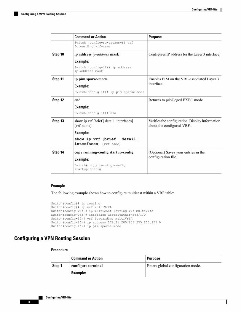
Configures IP address for the Layer 3 interface.ip address ip-address mask
Example:
Step 10
Switch (config-if)# ip addressip-address mask
Enables PIM on the VRF-associated Layer 3interface.
ip pim sparse-mode
Example:
Step 11
Switch(config-if)# ip pim sparse-mode
Returns to privileged EXEC mode.end
Example:
Step 12
Switch(config-if)# end
Verifies the configuration. Display informationabout the configured VRFs.
show ip vrf [brief | detail | interfaces][vrf-name]
Example:
Step 13
show ip vrf [brief | detail |
interfaces] [vrf-name]
(Optional) Saves your entries in theconfiguration file.
copy running-config startup-config
Example:
Step 14
Switch# copy running-configstartup-config
Example
The following example shows how to configure multicast within a VRF table:
Switch(config)# ip routingSwitch(config)# ip vrf multiVrfASwitch(config-vrf)# ip multicast-routing vrf multiVrfASwitch(config-vrf)# interface GigabitEthernet3/1/0Switch(config-if)# vrf forwarding multiVrfASwitch(config-if)# ip address 172.21.200.203 255.255.255.0Switch(config-if)# ip pim sparse-mode
Configuring a VPN Routing Session
Procedure
PurposeCommand or Action
Enters global configuration mode.configure terminal
Example:
Step 1
Configuring VRF-lite8
Configuring VRF-liteConfiguring a VPN Routing Session

PurposeCommand or ActionSwitch# configure terminal
Enables OSPF routing, specifies a VPNforwarding table, and enters router configurationmode.
router ospf process-id vrf vrf-name
Example:Switch(config)# router ospf process-idvrf vrf-name
Step 2
(Optional) Logs changes in the adjacency state(the default state).
log-adjacency-changes
Example:
Step 3
Switch(config-router)#log-adjacency-changes
Sets the switch to redistribute information fromthe BGP network to the OSPF network.
redistribute bgp autonomous-system-numbersubnets
Example:
Step 4
Switch(config-router)# redistribute bgpautonomous-system-number subnets
Defines a network address and mask on whichOSPF runs and the area ID for that networkaddress.
network network-number area area-id
Example:Switch(config-router)# networknetwork-number area area-id
Step 5
Returns to privileged EXEC mode.end
Example:
Step 6
Switch(config-router)# end
Verifies the configuration of the OSPF network.show ip ospf process-id
Example:
Step 7
Switch# show ip ospf process-id
(Optional) Saves your entries in theconfiguration file.
copy running-config startup-config
Example:
Step 8
Use the no router ospf process-id vrf vrf-nameglobal configuration command to disassociate
Switch# copy running-configstartup-config
the VPN forwarding table from the OSPFrouting process.
Example
Switch(config)# ip vrf VRF-REDSwitch(config-vrf)# rd 1:1Switch(config-vrf)# exitSwitch(config)# router eigrp virtual-nameSwitch(config-router)# address-family ipv4 vrf VRF-RED autonomous-system 1Switch(config-router-af)# network 10.0.0.0 0.0.0.255Switch(config-router-af)# topology baseSwitch(config-router-topology)# default-metric 10000 100 255 1 1500
Configuring VRF-lite9
Configuring VRF-liteConfiguring a VPN Routing Session

Switch(config-router-topology)# exit-af-topologySwitch(config-router-af)# exit-address-family
Configuring BGP PE to CE Routing Sessions
Procedure
PurposeCommand or Action
Enters global configuration mode.configure terminal
Example:
Step 1
Switch# configure terminal
Configures the BGP routing process with theAS number passed to other BGP routers andenters router configuration mode.
router bgp autonomous-system-number
Example:Switch(config)# router bgpautonomous-system-number
Step 2
Specifies a network and mask to announceusing BGP.
network network-numbermask network-mask
Example:
Step 3
Switch(config-router)# networknetwork-number mask network-mask
Sets the switch to redistribute OSPF internalroutes.
redistribute ospf process-id match internal
Example:
Step 4
Switch(config-router)# redistribute ospfprocess-id match internal
Defines a network address and mask on whichOSPF runs and the area ID for that networkaddress.
network network-number area area-id
Example:Switch(config-router)# networknetwork-number area area-id
Step 5
Defines BGP parameters for PE to CE routingsessions and enters VRF address-familymode.
address-family ipv4 vrf vrf-name
Example:
Step 6
Switch(config-router-af)# address-familyipv4 vrf vrf-name
Defines a BGP session between PE and CErouters.
neighbor address remote-as as-number
Example:
Step 7
Switch(config-router-af)# neighboraddress remote-as as-number
Activates the advertisement of the IPv4 addressfamily.
neighbor address activate
Example:
Step 8
Switch(config-router-af)# neighboraddress activate
Configuring VRF-lite10
Configuring VRF-liteConfiguring BGP PE to CE Routing Sessions

PurposeCommand or Action
Returns to privileged EXEC mode.end
Example:
Step 9
Switch(config-router-af)# end
Verifies BGP configuration.show ip bgp [ipv4] [neighbors]Step 10
Example: Use the no router bgpautonomous-system-number globalSwitch# show ip bgp [ipv4] [neighbors]configuration command to delete the BGProuting process. Use the command withkeywords to delete routing characteristics.
Configuring IPv4 VRFs
Procedure
PurposeCommand or Action
Enters global configuration mode.configure terminal
Example:
Step 1
Switch# configure terminal
Enters global configuration mode.ip routing
Example:
Step 2
Switch# configure terminal
Names the VRF and enters VRF configurationmode.
ip vrf vrf-name
Example:
Step 3
Switch(config)# ip vrf vrf-name
Creates a VRF table by specifying a routedistinguisher. Enter either an Autonomous
rd route-distinguisher
Example:
Step 4
System number number and an arbitrarySwitch(config-vrf)# rdroute-distinguisher
number (xxx:y) or an IP address and arbitrarynumber (A.B.C.D:y).
Creates a list of import, export, or import andexport route target communities for the
route-target {export | import | both}route-target-ext-community
Step 5
specified VRF. Enter either an AS systemExample: number and an arbitrary number (xxx:y) or anSwitch(config-vrf)# route-target {export| import | both}route-target-ext-community
IP address and an arbitrary number(A.B.C.D:y).
This command is effective only ifBGP is running.
Note
(Optional) Associates a route map with theVRF.
import map route-map
Example:
Step 6
Configuring VRF-lite11
Configuring VRF-liteConfiguring IPv4 VRFs

PurposeCommand or ActionSwitch(config-vrf)# import map route-map
Enters interface configuration mode andspecify the Layer 3 interface to be associated
interface interface-id
Example:
Step 7
with the VRF. The interface can be a routedport or SVI.Switch(config-vrf)# interface
interface-id
Associates the VRFwith the Layer 3 interface.vrf forwarding vrf-name
Example:
Step 8
Switch(config-if)# vrf forwardingvrf-name
Returns to privileged EXEC mode.end
Example:
Step 9
Switch(config-if)# end
Verifies the configuration. Displaysinformation about the configured VRFs.
show ip vrf [brief | detail | interfaces][vrf-name]
Example:
Step 10
Switch# show ip vrf [brief | detail |interfaces] [vrf-name]
(Optional) Saves your entries in theconfiguration file.
copy running-config startup-config
Example:
Step 11
For complete syntax and usageinformation for the followingcommands, see the switchcommand reference for this releaseand see the Cisco IOS SwitchingServices Command Reference.
NoteSwitch# copy running-configstartup-config
Use the no ip vrf vrf-name globalconfiguration command to delete a VRF andto remove all interfaces from it. Use the no vrfforwarding interface configuration commandto remove an interface from the VRF.
Configuring VRF-lite for IPv6
Configuring VRF-Aware ServicesIPv6 services can be configured on global interfaces and within the global routing instance. IPv6 services areenhanced to run on multiple routing instances; they are VRF-aware. Any configured VRF in the system canbe specified for a VRF-aware service.
Configuring VRF-lite12
Configuring VRF-liteConfiguring VRF-lite for IPv6

VRF-aware services are implemented in platform-independent modules. VRF provides multiple routinginstances in Cisco IOS. Each platform has its own limit on the number of VRFs it supports.
VRF-aware services have the following characteristics:
• The user can ping a host in a user-specified VRF.
• Neighbor Discovery entries are learned in separate VRFs. The user can display Neighbor Discovery(ND) entries for specific VRFs.
The following services are VRF-aware:
• Ping
• Unicast Reverse Path Forwarding (uRPF)
• Traceroute
• FTP and TFTP
• Telnet and SSH
• NTP
Configuring the User Interface for PINGPerform the following task to configure a VRF-aware ping:
Procedure
PurposeCommand or Action
Pings an IPv6 host or address in the specifiedVRF.
ping vrf vrf-name ipv6-host
Example:
Step 1
Switch# ping vrf vrf-name ipv6-host
Configuring the User Interface for uRPFYou can configure uRPF on an interface assigned to a VRF. Source lookup is performed in the VRF table
Procedure
PurposeCommand or Action
Enters global configuration mode.configure terminal
Example:
Step 1
Switch# configure terminal
Enters interface configuration mode andspecifies the Layer 3 interface to configure.
interface interface-id
Example:
Step 2
Switch (config)# interface interface-id
Configuring VRF-lite13
Configuring VRF-liteConfiguring the User Interface for PING

PurposeCommand or Action
Removes the interface from Layer 2configuration mode if it is a physical interface.
no switchport
Example:
Step 3
Switch (config-if)# no switchport
Configures VRF on the interface.vrf forwarding vrf-name
Example:
Step 4
Switch (config-if)# vrf forwardingvrf-name
Enters the IPv6 address for the interface.ipv6 address ip-address subnet-mask
Example:
Step 5
Switch (config-if)# ip address ip-addressmask
Enables uRPF on the interface.ipv6 verify unicast source reachable-via rxallow-default
Step 6
Example:Switch(config-if)# ipv6 verify unicastsource reachable-viarx allow-default
Returns to privileged EXEC mode.end
Example:
Step 7
Switch(config-if)# end
Configuring the User Interface for Traceroute
Procedure
PurposeCommand or Action
Specifies the name of a VPN VRF in which tofind the destination address.
traceroute vrf vrf-name ipv6address
Example:
Step 1
Switch# traceroute vrf vrf-nameipv6address
Configuring the User Interface for Telnet and SSH
Procedure
PurposeCommand or Action
Connects through Telnet to an IPv6 host oraddress in the specified VRF.
telnet ipv6-address/vrf vrf-name
Example:
Step 1
Switch# telnet ipv6-address/vrf vrf-name
Configuring VRF-lite14
Configuring VRF-liteConfiguring the User Interface for Traceroute

PurposeCommand or Action
Connects through SSH to an IPv6 host oraddress in the specified VRF.
ssh -l username -vrf vrf-name ipv6-host
Example:
Step 2
Switch# ssh -l username -vrf vrf-nameipv6-host
Configuring the User Interface for NTP
Procedure
PurposeCommand or Action
Enters the global configuration mode.configure terminal
Example:
Step 1
Device# configure terminal
Configure the NTP server in the specified VRF.ntp server vrf vrf-name ipv6-host
Example:
Step 2
Device(config)# ntp server vrf vrf-nameipv6-host
Configure the NTP peer in the specified VRF.ntp peer vrf vrf-name ipv6-host
Example:
Step 3
Device(config)# ntp peer vrf vrf-nameipv6-host
Configuring IPv6 VRFs
Procedure
PurposeCommand or Action
Enters global configuration mode.configure terminal
Example:
Step 1
Switch# configure terminal
Names the VRF and enters VRF configurationmode.
vrf definition vrf-name
Example:
Step 2
Switch(config)# vrf definition vrf-name
(Optional) Creates a VRF table by specifyinga route distinguisher. Enter either an
rd route-distinguisher
Example:
Step 3
Autonomous System number and an arbitrarySwitch(config-vrf)# rdroute-distinguisher
number (xxx:y) or an IP address and arbitrarynumber (A.B.C.D:y).
Configuring VRF-lite15
Configuring VRF-liteConfiguring the User Interface for NTP

PurposeCommand or Action
(Optional) IPv4 by default. ConfigurationMUST for IPv6.
address-family ipv4 | ipv6
Example:
Step 4
Switch(config-vrf)# address-family ipv4| ipv6
Creates a list of import, export, or import andexport route target communities for the
route-target {export | import | both}route-target-ext-community
Step 5
specified VRF. Enter either an AS systemExample: number and an arbitrary number (xxx:y) or anSwitch(config-vrf)# route-target {export| import | both}route-target-ext-community
IP address and an arbitrary number(A.B.C.D:y).
This command is effective only ifBGP is running.
Note
Exits VRF address-family configuration modeand return to VRF configuration mode.
exit-address-family
Example:
Step 6
Switch(config-vrf)# exit-address-family
Enters VRF configuration mode.vrf definition vrf-name
Example:
Step 7
Switch(config)# vrf definition vrf-name
Enables multicast specific RPF topology.ipv6 multicast multitopology
Example:
Step 8
Switch(config-vrf-af)# ipv6 multicastmultitopology
Enter multicast IPv6 address-family.address-family ipv6 multicast
Example:
Step 9
Switch(config-vrf)# address-family ipv6multicast
Returns to privileged EXEC mode.end
Example:
Step 10
Switch(config-vrf-af)# end
Example
This example shows how to configure VRFs:
Switch(config)# vrf definition redSwitch(config-vrf)# rd 100:1Switch(config-vrf)# address family ipv6Switch(config-vrf-af)# route-target both 200:1Switch(config-vrf)# exit-address-familySwitch(config-vrf)# vrf definition red
Configuring VRF-lite16
Configuring VRF-liteConfiguring IPv6 VRFs

Switch(config-if)# ipv6 multicast multitopologySwitch(config-if)# address-family ipv6 multicastSwitch(config-vrf-af)# endSwitch#
Associating Interfaces to the Defined VRFs
Procedure
PurposeCommand or Action
Enters interface configurationmode and specifythe Layer 3 interface to be associated with theVRF. The interface can be a routed port or SVI.
interface interface-id
Example:Switch(config-vrf)# interfaceinterface-id
Step 1
Removes the interface from configurationmodeif it is a physical interface.
no switchport
Example:
Step 2
Switch(config-if)# no switchport
Associates the VRF with the Layer 3 interface.vrf forwarding vrf-name
Example:
Step 3
Switch(config-if)# vrf forwardingvrf-name
Enable IPv6 on the interface.ipv6 enable
Example:
Step 4
Switch(config-if)# ipv6 enable
Enters the IPv6 address for the interface.ipv6 address ip-address subnet-mask
Example:
Step 5
Switch(config-if)# ipv6 addressip-address subnet-mask
Verifies the configuration. Displays informationabout the configured VRFs.
show ipv6 vrf [brief | detail | interfaces][vrf-name]
Example:
Step 6
Switch# show ipv6 vrf [brief | detail |interfaces] [vrf-name]
(Optional) Saves your entries in theconfiguration file.
copy running-config startup-config
Example:
Step 7
Switch# copy running-configstartup-config
Configuring VRF-lite17
Configuring VRF-liteAssociating Interfaces to the Defined VRFs

Example
This example shows how to associate an interface to VRFs:Switch(config-vrf)# interface ethernet0/1Switch(config-if)# vrf forwarding redSwitch(config-if)# ipv6 enableSwitch(config-if)# ipv6 address 5000::72B/64
Populate VRF with Routes via Routing Protocols
Configuring VRF Static Routes
Procedure
PurposeCommand or Action
Enters global configuration mode.configure terminal
Example:
Step 1
Switch# configure terminal
To configure static routes specific to VRF.ipv6 route [vrf vrf-name]ipv6-prefix/prefix-length {ipv6-address |
Step 2
interface-type interface-number[ipv6-address]}
Example:Switch(config)# ipv6 route [vrf vrf-name]ipv6-prefix/prefix-length {ipv6-address| interface-type interface-number[ipv6-address]}
Example
Switch(config)# ipv6 route vrf v6a 7000::/64 TenGigabitEthernet32 4000::2
Configuring OSPFv3 Router Process
Procedure
PurposeCommand or Action
Enters global configuration mode.configure terminal
Example:
Step 1
Switch# configure terminal
Enables OSPFv3 router configuration mode forthe IPv6 address family.
router ospfv3 process-id
Example:
Step 2
Configuring VRF-lite18
Configuring VRF-litePopulate VRF with Routes via Routing Protocols
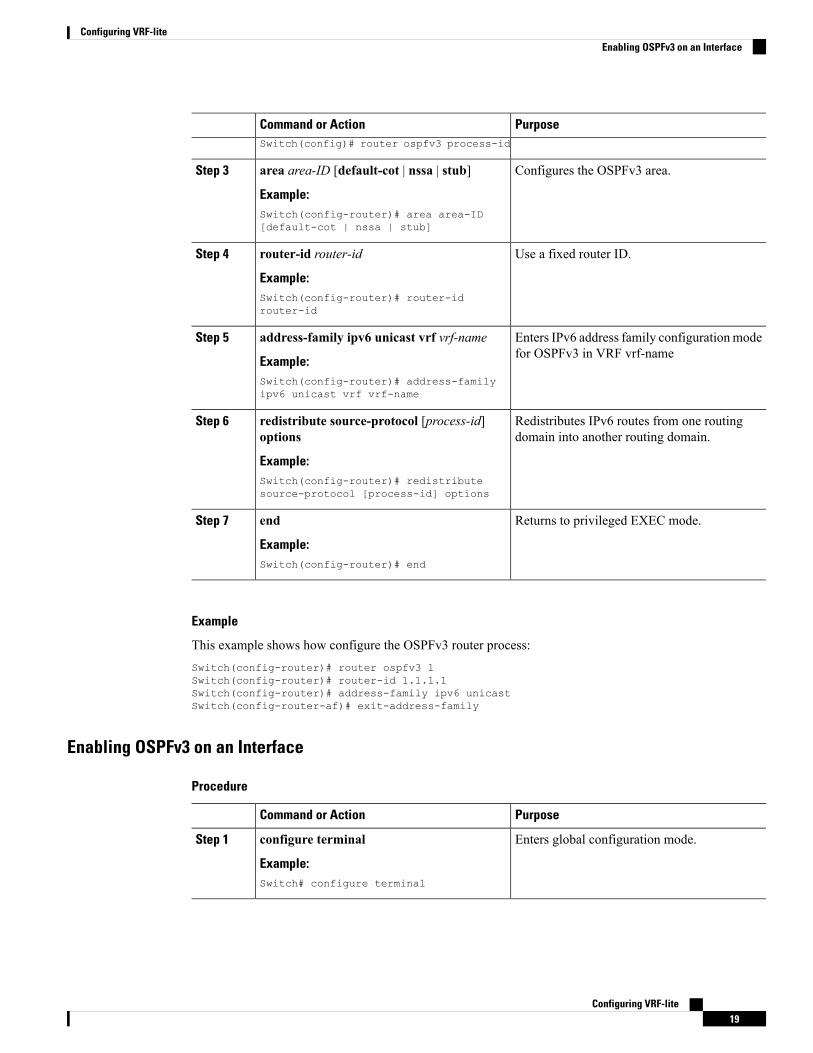
PurposeCommand or ActionSwitch(config)# router ospfv3 process-id
Configures the OSPFv3 area.area area-ID [default-cot | nssa | stub]
Example:
Step 3
Switch(config-router)# area area-ID[default-cot | nssa | stub]
Use a fixed router ID.router-id router-id
Example:
Step 4
Switch(config-router)# router-idrouter-id
Enters IPv6 address family configurationmodefor OSPFv3 in VRF vrf-name
address-family ipv6 unicast vrf vrf-name
Example:
Step 5
Switch(config-router)# address-familyipv6 unicast vrf vrf-name
Redistributes IPv6 routes from one routingdomain into another routing domain.
redistribute source-protocol [process-id]options
Example:
Step 6
Switch(config-router)# redistributesource-protocol [process-id] options
Returns to privileged EXEC mode.end
Example:
Step 7
Switch(config-router)# end
Example
This example shows how configure the OSPFv3 router process:Switch(config-router)# router ospfv3 1Switch(config-router)# router-id 1.1.1.1Switch(config-router)# address-family ipv6 unicastSwitch(config-router-af)# exit-address-family
Enabling OSPFv3 on an Interface
Procedure
PurposeCommand or Action
Enters global configuration mode.configure terminal
Example:
Step 1
Switch# configure terminal
Configuring VRF-lite19
Configuring VRF-liteEnabling OSPFv3 on an Interface
PurposeCommand or Action
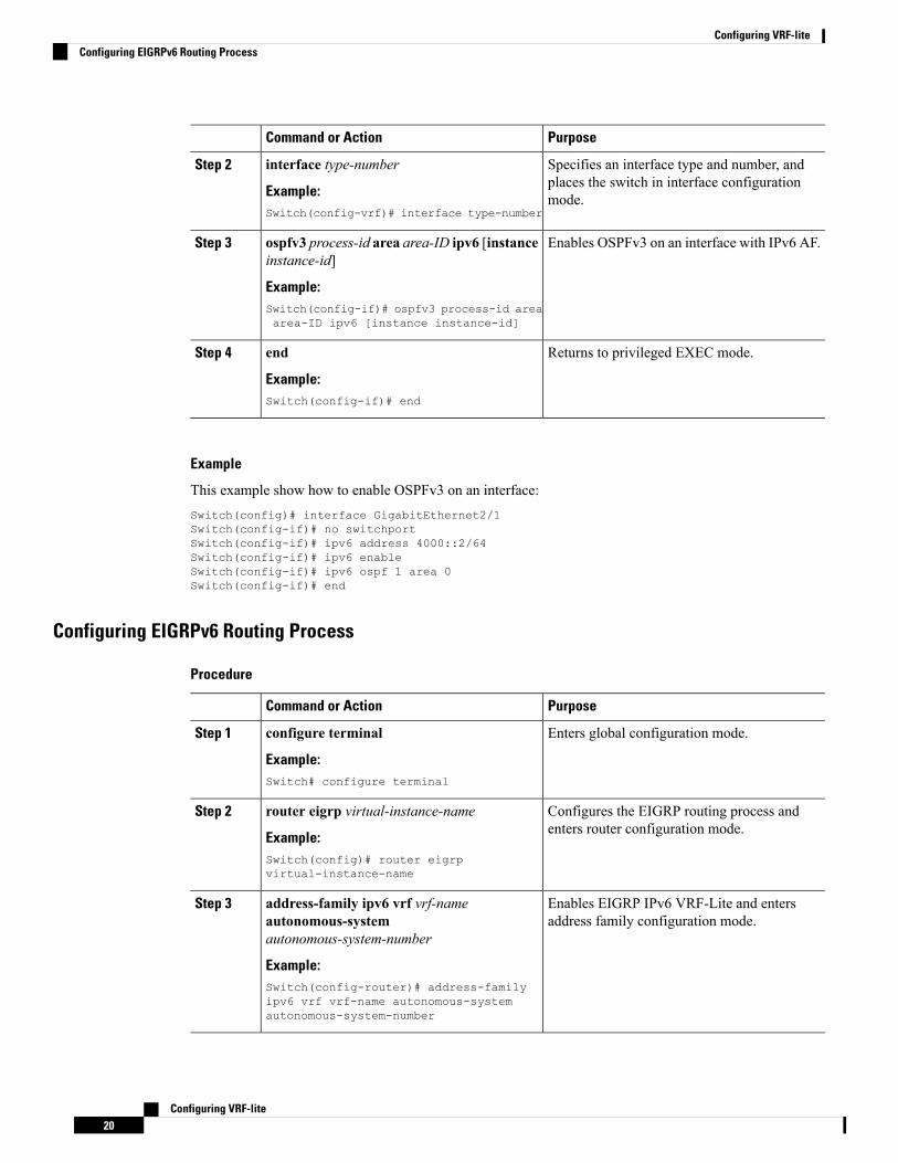
Specifies an interface type and number, andplaces the switch in interface configurationmode.
interface type-number
Example:Switch(config-vrf)# interface type-number
Step 2
Enables OSPFv3 on an interface with IPv6 AF.ospfv3 process-id area area-ID ipv6 [instanceinstance-id]
Step 3
Example:Switch(config-if)# ospfv3 process-id areaarea-ID ipv6 [instance instance-id]
Returns to privileged EXEC mode.end
Example:
Step 4
Switch(config-if)# end
Example
This example show how to enable OSPFv3 on an interface:Switch(config)# interface GigabitEthernet2/1Switch(config-if)# no switchportSwitch(config-if)# ipv6 address 4000::2/64Switch(config-if)# ipv6 enableSwitch(config-if)# ipv6 ospf 1 area 0Switch(config-if)# end
Configuring EIGRPv6 Routing Process
Procedure
PurposeCommand or Action
Enters global configuration mode.configure terminal
Example:
Step 1
Switch# configure terminal
Configures the EIGRP routing process andenters router configuration mode.
router eigrp virtual-instance-name
Example:
Step 2
Switch(config)# router eigrpvirtual-instance-name
Enables EIGRP IPv6 VRF-Lite and entersaddress family configuration mode.
address-family ipv6 vrf vrf-nameautonomous-systemautonomous-system-number
Step 3
Example:Switch(config-router)# address-familyipv6 vrf vrf-name autonomous-systemautonomous-system-number
Configuring VRF-lite20
Configuring VRF-liteConfiguring EIGRPv6 Routing Process

PurposeCommand or Action
Configures an EIGRP process to route IP trafficunder the specified topology instance and entersaddress family topology configuration mode.
topology {base | topology-name tid number
Example:Switch(config-router-af)# topology {base| topology-name tid number
Step 4
Exits address family topology configurationmode.
exit-aftopology
Example:
Step 5
Switch(config-router-af-topology)#exit-aftopology
Enables the use of a fixed router-id.eigrp router-id ip-address
Example:
Step 6
Switch(config-router)# eigrp router-idip-address
Exits router configuration mode.end
Example:
Step 7
Switch(config-router)# end
Example
This example shows how to configure an EIGRP routing process:
Switch(config)# router eigrp testSwitch(config-router)# address-family ipv6 unicast vrf b1 autonomous-system 10Switch(config-router-af)# topology baseSwitch(config-router-af-topology)# exit-af-topologySwitch(config-router)# eigrp router-id 2.3.4.5Switch(config-router)# exit-address-family
Configuring EBGPv6 Routing Process
Procedure
PurposeCommand or Action
Enters global configuration mode.configure terminal
Example:
Step 1
Switch# configure terminal
Enters router configuration mode for thespecified routing process.
router bgp as-number
Example:
Step 2
Switch(config)# router bgp as-number
Creates a multiprotocol BGP peer group.neighbor peer-group-name peer-group
Example:
Step 3
Configuring VRF-lite21
Configuring VRF-liteConfiguring EBGPv6 Routing Process

PurposeCommand or ActionSwitch(config-router)# neighborpeer-group-name peer-group
Adds the IPv6 address of the neighbor in thespecified autonomous system to the IPv6
neighbor {ip-address | ipv6-address[%] |peer-group-name}remote-as
Step 4
multiprotocol BGP neighbor table of the localrouter.
autonomous-system-number [alternate-asautonomous-system-number ...]
Example:Switch(config-router)# neighbor{ip-address | ipv6-address[%] |peer-group-name}remote-asautonomous-system-number [alternate-asautonomous-system-number ...]
Specifies the IPv6 address family, and entersaddress family configuration mode.
address-family ipv6 [vrf vrf-name] [unicast |multicast | vpnv6]
Step 5
Example: • The unicast keyword specifies the IPv6unicast address family. By default, theSwitch(config-router)# address-family
ipv6 [vrf vrf-name] [unicast | multicast| vpnv6]
switch is placed in configuration mode forthe IPv6 unicast address family if theunicast keyword is not specified with theaddress-family ipv6command.
• The multicast keyword specifies IPv6multicast address prefixes.
Assigns the IPv6 address of a BGP neighbor toa peer group.
neighbor ipv6-address peer-grouppeer-group-name
Example:
Step 6
Switch(config-router-af)# neighboripv6-address peer-group peer-group-name
Applies a route map to incoming or outgoingroutes. Changes to the route map will not take
neighbor {ip-address | peer-group-name |ipv6-address[%]}route-map map-name {in |out}
Step 7
effect for existing peers until the peering is resetor a soft reset is performed. Using the clear bgp
Example: ipv6 command with the soft and in keywordswill perform a soft reset.Switch(config-router-af)# neighbor
{ip-address | peer-group-name |ipv6-address[%]}route-map map-name {in| out}
Exits address family configuration mode, andreturns the router to router configuration mode.
exit
Example:
Step 8
Switch(config-router-af)# exit
Example
This example shows how to configure EBRPv6:
Configuring VRF-lite22
Configuring VRF-liteConfiguring EBGPv6 Routing Process

Switch(config)# router bgp 2Switch(config-router)# bgp router-id 2.2.2.2Switch(config-router)# bgp log-neighbor-changesSwitch(config-router)# no bgp default ipv4-unicastSwitch(config-router)# neighbor 2500::1 remote-as 1Switch(config-router)# neighbor 4000::2 remote-as 3Switch(config-router)# address-family ipv6 vrf b1Switch(config-router-af)# network 2500::/64Switch(config-router-af)# network 4000::/64Switch(config-router-af)# neighbor 2500::1 remote-as 1Switch(config-router-af)# neighbor 2500::1 activateSwitch(config-router-af)# neighbor 4000::2 remote-as 3Switch(config-router-af)# neighbor 4000::2 activateSwitch(config-router-af)# exit-address-family
Additional Information for VRF-lite
VPN Co-existence Between IPv4 and IPv6Backward compatibility between the “older” CLI for configuring IPv4 and the “new” CLI for IPv6 exists.This means that a configuration might contain both CLI. The IPv4 CLI retains the ability to have on the sameinterface, an IP address defined within a VRF as well as an IPv6 address defined in the global routing table.
For example:vrf definition redrd 100:1address family ipv6route-target both 200:1exit-address-family!ip vrf bluerd 200:1route-target both 200:1!interface Ethernet0/0vrf forwarding redip address 50.1.1.2 255.255.255.0ipv6 address 4000::72B/64!interface Ethernet0/1vrf forwarding blueip address 60.1.1.2 255.255.255.0ipv6 address 5000::72B/64
In this example, all addresses (v4 and v6) defined for Ethernet0/0 refer to VRF red whereas for Ethernet0/1,the IP address refers to VRF blue but the ipv6 address refers to the global IPv6 routing table.
Verifying VRF-lite Configuration
Displaying IPv4 VRF-lite StatusTo display information about VRF-lite configuration and status, perform one of the following tasks:
Configuring VRF-lite23
Configuring VRF-liteAdditional Information for VRF-lite
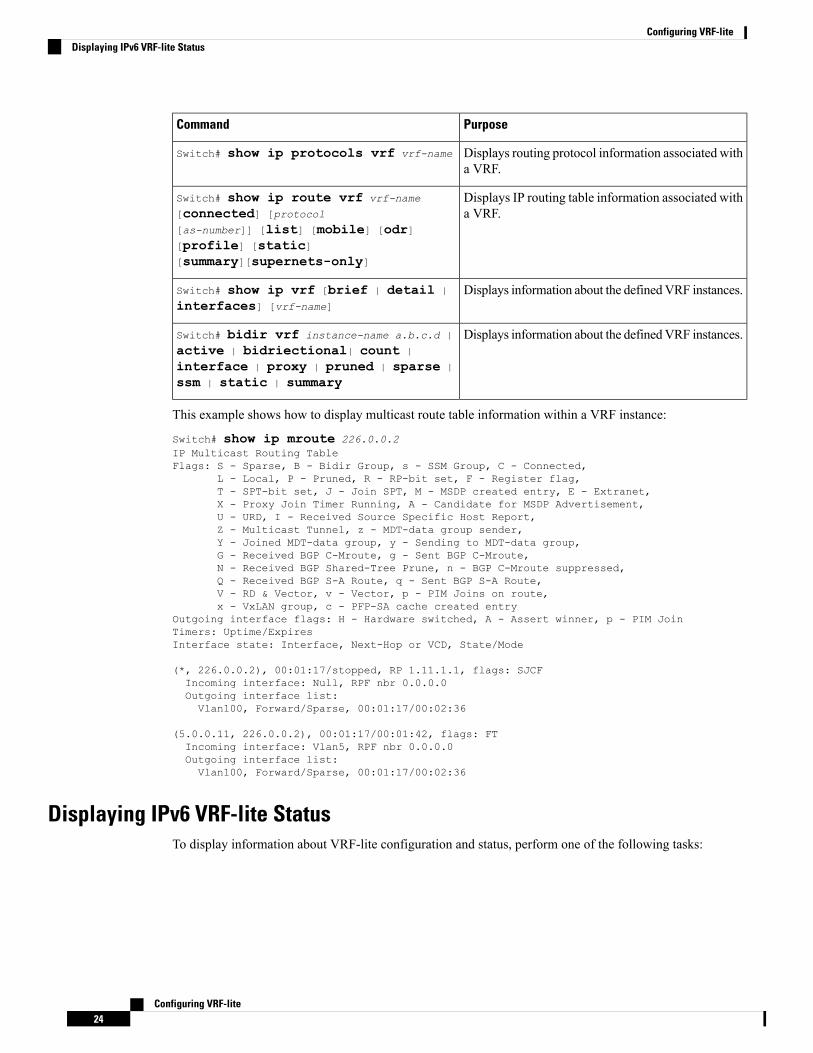
PurposeCommand
Displays routing protocol information associated witha VRF.
Switch# show ip protocols vrf vrf-name
Displays IP routing table information associated witha VRF.
Switch# show ip route vrf vrf-name
[connected] [protocol
[as-number]] [list] [mobile] [odr][profile] [static][summary][supernets-only]
Displays information about the definedVRF instances.Switch# show ip vrf [brief | detail |
interfaces] [vrf-name]
Displays information about the definedVRF instances.Switch# bidir vrf instance-name a.b.c.d |
active | bidriectional| count |
interface | proxy | pruned | sparse |
ssm | static | summary
This example shows how to display multicast route table information within a VRF instance:
Switch# show ip mroute 226.0.0.2IP Multicast Routing TableFlags: S - Sparse, B - Bidir Group, s - SSM Group, C - Connected,
L - Local, P - Pruned, R - RP-bit set, F - Register flag,T - SPT-bit set, J - Join SPT, M - MSDP created entry, E - Extranet,X - Proxy Join Timer Running, A - Candidate for MSDP Advertisement,U - URD, I - Received Source Specific Host Report,Z - Multicast Tunnel, z - MDT-data group sender,Y - Joined MDT-data group, y - Sending to MDT-data group,G - Received BGP C-Mroute, g - Sent BGP C-Mroute,N - Received BGP Shared-Tree Prune, n - BGP C-Mroute suppressed,Q - Received BGP S-A Route, q - Sent BGP S-A Route,V - RD & Vector, v - Vector, p - PIM Joins on route,x - VxLAN group, c - PFP-SA cache created entry
Outgoing interface flags: H - Hardware switched, A - Assert winner, p - PIM JoinTimers: Uptime/ExpiresInterface state: Interface, Next-Hop or VCD, State/Mode
(*, 226.0.0.2), 00:01:17/stopped, RP 1.11.1.1, flags: SJCFIncoming interface: Null, RPF nbr 0.0.0.0Outgoing interface list:Vlan100, Forward/Sparse, 00:01:17/00:02:36
(5.0.0.11, 226.0.0.2), 00:01:17/00:01:42, flags: FTIncoming interface: Vlan5, RPF nbr 0.0.0.0Outgoing interface list:Vlan100, Forward/Sparse, 00:01:17/00:02:36
Displaying IPv6 VRF-lite StatusTo display information about VRF-lite configuration and status, perform one of the following tasks:
Configuring VRF-lite24
Configuring VRF-liteDisplaying IPv6 VRF-lite Status

PurposeCommand
Displays routing protocol information associated witha VRF.
Switch# show ipv6 mroute vrfinstance-name [X:X:X:X::X/<0-128>] [bgp][connected] [eigrp] [interface] [isis][local] [nd] [nsf] [ospf ] [repair][rip] [shortcut] [static] [summary][tag] [updated] [watch]
Displays information about the definedVRF instances.Switch# show ipv6 mfib vrf instance-name
a.b.c.d | active | all | count |
linkscope| route | summary |
update-sets | verbose
This example shows how to display multicast route table information within a VRF instance:
show ipv6 mroute vrf vrf1 FF05:ABCD:0:0:0:0:0:1Multicast Routing TableFlags: S - Sparse, B - Bidir Group, s - SSM Group,C - Connected, L - Local, I - Received Source Specific Host Report,P - Pruned, R - RP-bit set, F - Register flag, T - SPT-bit set,J - Join SPT, Y - Joined MDT-data group,y - Sending to MDT-data group
g - BGP signal originated, G - BGP Signal received,N - BGP Shared-Tree Prune received, n - BGP C-Mroute suppressed,q - BGP Src-Active originated, Q - BGP Src-Active receivedE - ExtranetTimers: Uptime/ExpiresInterface state: Interface, State
(*, FF05:ABCD::1), 00:06:22/never, RP 1010:ABCD::10, flags: SCJIncoming interface: Port-channel33RPF nbr: FE80::2E31:24FF:FE06:134AImmediate Outgoing interface list:TenGigabitEthernet4/0/18, Forward, 00:06:22/never
(3232:ABCD::2, FF05:ABCD::1), 00:04:54/00:02:16, flags: SJTIncoming interface: Port-channel33RPF nbr: FE80::2E31:24FF:FE06:134AInherited Outgoing interface list:TenGigabitEthernet4/0/18, Forward, 00:06:22/never
The following example displays the output of show ipv6 mfib command.
Switch# show ipv6 mfib vrf vrf1 FF05:ABCD:0:0:0:0:0:1Entry Flags: C - Directly Connected, S - Signal, IA - Inherit A flag,
ET - Data Rate Exceeds Threshold, K - KeepaliveDDE - Data Driven Event, HW - Hardware InstalledME - MoFRR ECMP entry, MNE - MoFRR Non-ECMP entry, MP - MFIBMoFRR Primary, RP - MRIB MoFRR Primary, P - MoFRR PrimaryMS - MoFRR Entry in Sync, MC - MoFRR entry in MoFRR Client.
I/O Item Flags: IC - Internal Copy, NP - Not platform switched,NS - Negate Signalling, SP - Signal Present,A - Accept, F - Forward, RA - MRIB Accept, RF - MRIB Forward,MA - MFIB Accept, A2 - Accept backup,RA2 - MRIB Accept backup, MA2 - MFIB Accept backup
Forwarding Counts: Pkt Count/Pkts per second/Avg Pkt Size/Kbits per secondOther counts: Total/RPF failed/Other dropsI/O Item Counts: FS Pkt Count/PS Pkt Count
Configuring VRF-lite25
Configuring VRF-liteDisplaying IPv6 VRF-lite Status

VRF testvrf1(*,FF05:ABCD::1) Flags: C HWSW Forwarding: 0/0/0/0, Other: 0/0/0HW Forwarding: 295/0/512/0, Other: 0/0/0Port-channel33 Flags: A NSTenGigabitEthernet4/0/18 Flags: F NSPkts: 0/0
(3232:ABCD::2,FF05:ABCD::1) Flags: HWSW Forwarding: 50/0/512/0, Other: 111/0/111HW Forwarding: 4387686/14849/512/59398, Other: 0/0/0Port-channel33 Flags: ATenGigabitEthernet4/0/18 Flags: F NSPkts: 0/50
Switch#
Configuration Examples for VRF-lite
Configuration Example for IPv4 VRF-liteOSPF is the protocol used in VPN1, VPN2, and the global network. BGP is used in the CE to PE connections.The example commands show how to configure the CE switch S8 and include the VRF configuration forswitches S20 and S11 and the PE router commands related to traffic with switch S8. Commands for configuringthe other switches are not included but would be similar.Figure 2: VRF-lite Configuration Example
Configuring VRF-lite26
Configuring VRF-liteConfiguration Examples for VRF-lite

Configuring Switch S8
On switch S8, enable routing and configure VRF.Switch# configure terminalEnter configuration commands, one per line. End with CNTL/Z.Switch(config)# ip routingSwitch(config)# ip vrf v11Switch(config-vrf)# rd 800:1Switch(config-vrf)# route-target export 800:1Switch(config-vrf)# route-target import 800:1Switch(config-vrf)# exitSwitch(config)# ip vrf v12Switch(config-vrf)# rd 800:2Switch(config-vrf)# route-target export 800:2Switch(config-vrf)# route-target import 800:2Switch(config-vrf)# exit
Configure the loopback and physical interfaces on switch S8. Fast Ethernet interface 3/5 is a trunk connectionto the PE. Interfaces 3/7 and 3/11 connect to VPNs:Switch(config)# interface loopback1Switch(config-if)# vrf forwarding v11Switch(config-if)# ip address 8.8.1.8 255.255.255.0Switch(config-if)# exit
Switch(config)# interface loopback2Switch(config-if)# vrf forwarding v12Switch(config-if)# ip address 8.8.2.8 255.255.255.0Switch(config-if)# exit
Switch(config)# interface FastEthernet3/5Switch(config-if)# switchport trunk encapsulation dot1qSwitch(config-if)# switchport mode trunkSwitch(config-if)# no ip addressSwitch(config-if)# exit
Switch(config)# interface FastEthernet3/8Switch(config-if)# switchport access vlan 208Switch(config-if)# no ip addressSwitch(config-if)# exit
Switch(config)# interface FastEthernet3/11Switch(config-if)# switchport trunk encapsulation dot1qSwitch(config-if)# switchport mode trunkSwitch(config-if)# no ip addressSwitch(config-if)# exit
Configure the VLANs used on switch S8. VLAN 10 is used by VRF 11 between the CE and the PE. VLAN20 is used by VRF 12 between the CE and the PE. VLANs 118 and 208 are used for VRF for the VPNs thatinclude switch S11 and switch S20, respectively:Switch(config)# interface Vlan10Switch(config-if)# vrf forwarding v11Switch(config-if)# ip address 38.0.0.8 255.255.255.0Switch(config-if)# exit
Switch(config)# interface Vlan20Switch(config-if)# vrf forwarding v12Switch(config-if)# ip address 83.0.0.8 255.255.255.0Switch(config-if)# exit
Switch(config)# interface Vlan118Switch(config-if)# vrf forwarding v12Switch(config-if)# ip address 118.0.0.8 255.255.255.0
Configuring VRF-lite27
Configuring VRF-liteConfiguration Example for IPv4 VRF-lite
Switch(config-if)# exit
Switch(config)# interface Vlan208Switch(config-if)# vrf forwarding v11Switch(config-if)# ip address 208.0.0.8 255.255.255.0Switch(config-if)# exit
Configure OSPF routing in VPN1 and VPN2:Switch(config)# router ospf 1 vrf vl1Switch(config-router)# redistribute bgp 800 subnetsSwitch(config-router)# network 208.0.0.0 0.0.0.255 area 0Switch(config-router)# exitSwitch(config)# router ospf 2 vrf vl2Switch(config-router)# redistribute bgp 800 subnetsSwitch(config-router)# network 118.0.0.0 0.0.0.255 area 0Switch(config-router)# exit
Configure BGP for CE to PE routing:Switch(config)# router bgp 800Switch(config-router)# address-family ipv4 vrf vl2Switch(config-router-af)# redistribute ospf 2 match internalSwitch(config-router-af)# neighbor 83.0.0.3 remote-as 100Switch(config-router-af)# neighbor 83.0.0.3 activateSwitch(config-router-af)# network 8.8.2.0 mask 255.255.255.0Switch(config-router-af)# exit
Switch(config-router)# address-family ipv4 vrf vl1Switch(config-router-af)# redistribute ospf 1 match internalSwitch(config-router-af)# neighbor 38.0.0.3 remote-as 100Switch(config-router-af)# neighbor 38.0.0.3 activateSwitch(config-router-af)# network 8.8.1.0 mask 255.255.255.0Switch(config-router-af)# end
Configuring Switch S20
Configure S20 to connect to CE:Switch# configure terminalEnter configuration commands, one per line. End with CNTL/Z.Switch(config)# ip routingSwitch(config)# interface Fast Ethernet 0/7Switch(config-if)# no switchportSwitch(config-if)# ip address 208.0.0.20 255.255.255.0Switch(config-if)# exit
Switch(config)# router ospf 101Switch(config-router)# network 208.0.0.0 0.0.0.255 area 0Switch(config-router)# end
Configuring Switch S11
Configure S11 to connect to CE:Switch# configure terminalEnter configuration commands, one per line. End with CNTL/Z.Switch(config)# ip routingSwitch(config)# interface Gigabit Ethernet 0/3Switch(config-if)# switchport trunk encapsulation dot1qSwitch(config-if)# switchport mode trunkSwitch(config-if)# no ip addressSwitch(config-if)# exit
Switch(config)# interface Vlan118
Configuring VRF-lite28
Configuring VRF-liteConfiguration Example for IPv4 VRF-lite

Switch(config-if)# ip address 118.0.0.11 255.255.255.0Switch(config-if)# exit
Switch(config)# router ospf 101Switch(config-router)# network 118.0.0.0 0.0.0.255 area 0Switch(config-router)# end
Configuring the PE Switch S3
On switch S3 (the router), these commands configure only the connections to switch S8:Router# configure terminalEnter configuration commands, one per line. End with CNTL/Z.Router(config)# ip vrf v1Router(config-vrf)# rd 100:1Router(config-vrf)# route-target export 100:1Router(config-vrf)# route-target import 100:1Router(config-vrf)# exit
Router(config)# ip vrf v2Router(config-vrf)# rd 100:2Router(config-vrf)# route-target export 100:2Router(config-vrf)# route-target import 100:2Router(config-vrf)# exit
Router(config)# ip cefRouter(config)# interface Loopback1Router(config-if)# vrf forwarding v1Router(config-if)# ip address 3.3.1.3 255.255.255.0Router(config-if)# exit
Router(config)# interface Loopback2Router(config-if)# vrf forwarding v2Router(config-if)# ip address 3.3.2.3 255.255.255.0Router(config-if)# exit
Router(config)# interface Fast Ethernet3/0.10Router(config-if)# encapsulation dot1q 10Router(config-if)# vrf forwarding v1Router(config-if)# ip address 38.0.0.3 255.255.255.0Router(config-if)# exit
Router(config)# interface Fast Ethernet3/0.20Router(config-if)# encapsulation dot1q 20Router(config-if)# vrf forwarding v2Router(config-if)# ip address 83.0.0.3 255.255.255.0Router(config-if)# exit
Router(config)# router bgp 100Router(config-router)# address-family ipv4 vrf v2Router(config-router-af)# neighbor 83.0.0.8 remote-as 800Router(config-router-af)# neighbor 83.0.0.8 activateRouter(config-router-af)# network 3.3.2.0 mask 255.255.255.0Router(config-router-af)# exitRouter(config-router)# address-family ipv4 vrf vlRouter(config-router-af)# neighbor 83.0.0.8 remote-as 800Router(config-router-af)# neighbor 83.0.0.8 activateRouter(config-router-af)# network 3.3.1.0 mask 255.255.255.0Router(config-router-af)# end
Configuring VRF-lite29
Configuring VRF-liteConfiguration Example for IPv4 VRF-lite

Configuration Example for IPv6 VRF-liteThe following topology illustrates how to use OSPFv3 for CE-PE routing.Figure 3: VRF-lite Configuration Example
Configuring CE1 Switch
ipv6 unicast-routingvrf definition v1rd 100:1!address-family ipv6exit-address-family!
vrf definition v2rd 200:1!address-family ipv6exit-address-family!
interface Vlan100vrf forwarding v1ipv6 address 1000:1::1/64ospfv3 100 ipv6 area 0!
interface Vlan200vrf forwarding v2ipv6 address 2000:1::1/64ospfv3 200 ipv6 area 0!
interface GigabitEthernet 1/0/1switchport access vlan 100end
interface GigabitEthernet 1/0/2switchport access vlan 200end
interface GigabitEthernet 1/0/24switchport trunk encapsulation dot1q
Configuring VRF-lite30
Configuring VRF-liteConfiguration Example for IPv6 VRF-lite
switchport mode trunkend
router ospfv3 100router-id 10.10.10.10!address-family ipv6 unicast vrf v1redistribute connectedarea 0 normalexit-address-family!
router ospfv3 200router-id 20.20.20.20!address-family ipv6 unicast vrf v2redistribute connectedarea 0 normalexit-address-family!
Configuring PE Switch
ipv6 unicast-routing
vrf definition v1rd 100:1!address-family ipv6exit-address-family!
vrf definition v2rd 200:1!address-family ipv6exit-address-family!interface Vlan600vrf forwarding v1no ipv6 addressipv6 address 1000:1::2/64ospfv3 100 ipv6 area 0!
interface Vlan700vrf forwarding v2no ipv6 addressipv6 address 2000:1::2/64ospfv3 200 ipv6 area 0!
interface Vlan800vrf forwarding v1ipv6 address 3000:1::7/64ospfv3 100 ipv6 area 0!interface Vlan900vrf forwarding v2ipv6 address 4000:1::7/64ospfv3 200 ipv6 area 0!
interface GigabitEthernet 1/0/1
Configuring VRF-lite31
Configuring VRF-liteConfiguration Example for IPv6 VRF-lite

switchport trunk encapsulation dot1qswitchport mode trunkexit
interface GigabitEthernet 1/0/2switchport trunk encapsulation dot1q
switchport mode trunkexit
router ospfv3 100router-id 30.30.30.30!address-family ipv6 unicast vrf v1redistribute connectedarea 0 normalexit-address-family!address-family ipv6 unicast vrf v2redistribute connectedarea 0 normalexit-address-family!
Configuring CE2 Switch
ipv6 unicast-routing
vrf definition v1rd 100:1!address-family ipv6exit-address-family!
vrf definition v2rd 200:1!address-family ipv6exit-address-family!
interface Vlan100vrf forwarding v1
ipv6 address 1000:1::3/64ospfv3 100 ipv6 area 0!
interface Vlan200vrf forwarding v2ipv6 address 2000:1::3/64ospfv3 200 ipv6 area 0!
interface GigabitEthernet 1/0/1switchport access vlan 100end
interface GigabitEthernet 1/0/2switchport access vlan 200end
interface GigabitEthernet 1/0/24
Configuring VRF-lite32
Configuring VRF-liteConfiguration Example for IPv6 VRF-lite

switchport trunk encapsulation dot1qswitchport mode trunkend
router ospfv3 100router-id 40.40.40.40!address-family ipv6 unicast vrf v1redistribute connectedarea 0 normalexit-address-family!
router ospfv3 200router-id 50.50.50.50!address-family ipv6 unicast vrf v2redistribute connected
area 0 normalexit-address-family!
Feature History and Information for Multicast VRF-liteFeature InformationReleaseFeature Name
IPv6 VRF-Lite allows aservice provider tosupport two or moreVPNswith overlapping IPaddresses using oneinterface.
This feature wasintroduced.
IPv6 Multicast supportwith VRF-Lite
Configuring VRF-lite33
Configuring VRF-liteFeature History and Information for Multicast VRF-lite
Configuring VRF-lite34
Configuring VRF-liteFeature History and Information for Multicast VRF-lite