CIRCULATING PUMPS WITA U - heat-tech.co.il WITA U.pdf · CIRCULATING PUMPS WITA U. ADVANTAGES OF...
6
CIRCULATING PUMPS WITA U
Transcript of CIRCULATING PUMPS WITA U - heat-tech.co.il WITA U.pdf · CIRCULATING PUMPS WITA U. ADVANTAGES OF...

CIRCULATING PUMPS
WITA U

ADVANTAGES OF WITA CIRCULATING PUMPS
MOTOR - SYSTEM WITAMonolith rotor can - INOXHermetic closed rotorCeramic cut shaftCast iron casing, kataphorisedCeramic shaft, drilled with reversible valve
Pump structure
1. Pump body - GG 25 cast iron2. Electric box3. Motor casting - aluminium4. Pump motor stator5. Motor sleeve - stainless steel6. Motor rotor7. Ceramic bearing8. Vent cap9. Pump shaft10. Ceramic bearing / graphite alloy11. Bearing plate - stainless steel12. Pump impeller - technical polymer13. Ring - stainless steel
1 2
3
45
67
8
9 10
11
12
13
Mounting
1
2
3
4
5
6
7
8
910
11
12
13
How does the centrifugal pump work?An increase in the fluid pressure from the pump inlet to its outlet is createdwhen the pump is in operation. This pressure difference drives the fluidthrough the system or plant.The centrifugal pump creates an increase in pressure by transferring mechanicalenergy from the motor to the fluid through the rotating impeller.The fluid flows from the inlet to the impeller centre and out along its blades.The centrifugal force hereby increases the fluid velocity and consequentlyalso the kinetic energy is transformed to pressure.
The pump must be mounted in a way so that the shaft isin ahorizontal position. Furthermore, during the firststart-up the pump should be bled using a cap.
1 2 3 4 5 6 7 Q(m /h)3
1
2
3
4
5
6
7
Hm
U 25
1 2 3 4 5 6 7 Q(m /h)3
1
2
3
4
5
6
7
Hm
U 35
1 2 3 4 5 6 7 Q(m /h)3
1
2
3
4
5
6
7
Hm
U 55
1 2 3 4 5 6 7 Q(m /h)3
1
2
3
4
5
6
7
Hm
U 65
1 2 3 4 5 6 7 Q(m /h)3
1
2
3
4
5
6
7
Hm
U 75
IN (A) P1 (W)
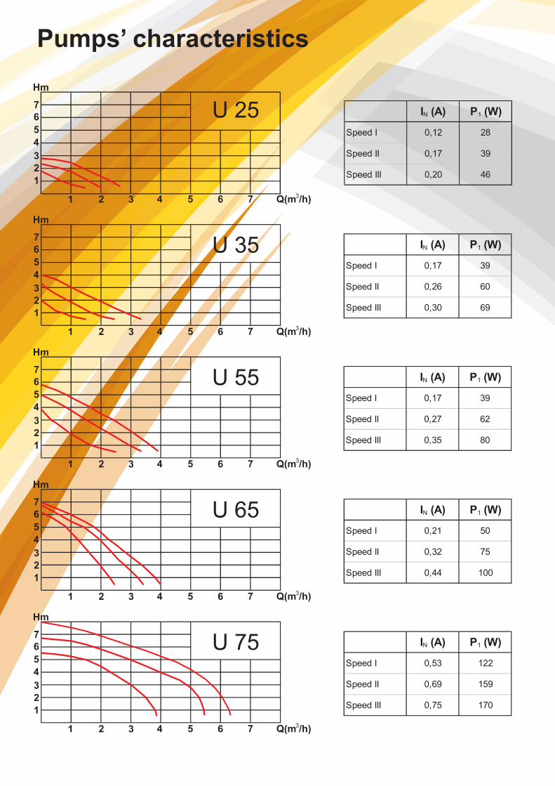
Speed I 0,12 28
Speed II 0,17 39
Speed III 0,20 46
IN (A) P1 (W)
Speed I 0,53 122
Speed II 0,69 159
Speed III 0,75 170
IN (A) P1 (W)
Speed I 0,21 50
Speed II 0,32 75
Speed III 0,44 100
IN (A) P1 (W)
Speed I 0,17 39
Speed II 0,27 62
Speed III 0,35 80
IN (A) P1 (W)
Speed I 0,17 39
Speed II 0,26 60
Speed III 0,30 69
Pumps’ characteristics

DIMENSION DIAGRAMS
110 -
180
135118
G 1” - G 2” G 1” - G 2”
110 -
180
144130
G 1” , G 1 1/4”, G 1 1/2”(standard) , G 2”L 180mm(standard) , 130mm , 110mm(bras)
G 1” , G 1 1/4”, G 1 1/2”(standard) , G 2”L 180mm(standard) , 130mm , 110mm(bras)
U 25, 35, 55 U 65Technicaldata
U 75
Pump type U 25 U 35 U 55 U 65 U 75
Max.working pressure 10 bar 10 bar 10 bar 10 bar 10 bar
Protection IP 44 44 44 44 44
Isolation class F F F F F
Phase 1 1 1 1 1
SCRFD: 230V 230V 230V 230V 230V
Condenser capacity 1,5µF 1,5µF 2,5µF 5µF 5µF
Frequency 50Hz 50Hz 50Hz 50Hz 50Hz
Liquid Min. Temperature +5°C +5°C +5°C +5°C +5°C
Liquid Max. Temperature 110°C 110°C 110°C 110°C 110°C
Synthetic impeler technopolymer technopolymer technopolymer technopolymer technopolymer
Pump body cast iron GG25 cast iron GG25 cast iron GG25 cast iron GG25 cast iron GG25
Engine case Al. Al. Al. Al. Al.
Threaded connection size G 11/2" G 2" G 11/2" G 2" G 11/2" G 2" G 11/2" G 2" G 11/2" G 2"
Nominal width DN 25, DN 32 DN 25, DN 32 DN 25, DN 32 DN 25, DN 32 DN 25, DN 32
Nominal pressure PN 10 PN 10 PN 10 PN 10 PN 10
Engine protection no, short-circuit prot. no, short-circuit prot. no, short-circuit prot. no, short-circuit prot. no, short-circuit prot.
Ambient temp.(by 80°C/med.t.) 40°C 40°C 40°C 40°C 40°C
According standards CE, B, GS-TÜV CE, B, GS-TÜV CE, B, GS-TÜV CE, B, GS-TÜV CE, B, GS-TÜV
Max. Head H [m] 3 4 6 7 8
Max. Flow Q [ltr/h] 2400 3000 3800 4000 6500
Number of levels 3 3 3 3 3
Level 1 IN(A) / P1(W) 0,12 / 28 0,17 / 39 0,17 / 39 0,21 / 50 0,53 / 122
Level 2 IN(A) / P1(W) 0,17 / 39 0,26 / 60 0,27 / 62 0,32 / 75 0,69 / 159
Level 3 IN(A) / P1(W) 0,20 / 46 0,30 / 69 0,35 / 80 0,44 / 100 0,75 / 170
Junction box position 9 H 9 H 9 H 9 H 9 H
Lenght 180mm 180mm 180mm 180mm 180mm
Weight netto 2,46kg 2,46kg 2,51kg 3kg 4,80kg
Description

DIMENSIONSWITA U 25 Pump
WITA U 35 Pump
WITA U 55 Pump
WITA U 65 Pump
WITA U 75 Pump
Article Pump bodyLenght(mm)
DNExternalthread
H(m)Power
consumption(W)
U 25-25 180 circulation pump Cast iron 180 25 G 1 1/2" 2,5 28-46
U 25-15 180 circulation pump Cast iron 130 15 G 1" 2,5 28-46
U 25-20 130 circulation pump Cast iron 130 20 G 1 1/4" 2,5 28-46
U 25-25 130 circulation pump Cast iron 130 25 G 1 1/2" 2,5 28-46
U 25-20 180 circulation pump Cast iron 180 20 G 1 1/4" 2,5 28-46
U 25-32 180 circulation pump Cast iron 180 32 G 2" 2,5 28-46
U 25-20 SB circulation pump Brass 110 20 G 1 1/4" 2,5 28-46
U 25-25 SB circulation pump Brass 110 25 G 1 1/2" 2,5 28-46
Article Pump bodyLenght(mm)
DNExternalthread
H(m)Power
consumption(W)
U 35-25 180 circulation pump Cast iron 180 25 G 1 1/2" 4 28-63
U 35-15 180 circulation pump Cast iron 130 15 G 1" 4 28-63
U 35-20 130 circulation pump Cast iron 130 20 G 1 1/4" 4 28-63
U 35-25 130 circulation pump Cast iron 130 25 G 1 1/2" 4 28-63
U 35-20 180 circulation pump Cast iron 180 20 G 1 1/4" 4 28-63
U 35-32 180 circulation pump Cast iron 180 32 G 2" 4 28-63
U 35-20 SB circulation pump Brass 110 20 G 1 1/4" 4 28-63
U 35-25 SB circulation pump Brass 110 25 G 1 1/2" 4 28-63
Article Pump bodyLenght(mm)
DNExternalthread
H(m)Power
consumption(W)
U 55-25 180 circulation pump Cast iron 180 25 G 1 1/2" 6 39-80
U 55-15 180 circulation pump Cast iron 130 15 G 1" 6 39-80
U 55-20 130 circulation pump Cast iron 130 20 G 1 1/4" 6 39-80
U 55-25 130 circulation pump Cast iron 130 25 G 1 1/2" 6 39-80
U 55-20 180 circulation pump Cast iron 180 20 G 1 1/4" 6 39-80
U 55-32 180 circulation pump Cast iron 180 32 G 2" 6 39-80
U 55-20 SB circulation pump Brass 110 20 G 1 1/4" 6 39-80
U 55-25 SB circulation pump Brass 110 25 G 1 1/2" 6 39-80
Article Pump bodyLenght(mm)
DNExternalthread
H(m)Power
consumption(W)
U 65-25 180 circulation pump Cast iron 180 25 G 1 1/2" 6,5 50-100
U 65-15 180 circulation pump Cast iron 130 15 G 1" 6,5 50-100
U 65-20 130 circulation pump Cast iron 130 20 G 1 1/4" 6,5 50-100
U 65-25 130 circulation pump Cast iron 130 25 G 1 1/2" 6,5 50-100
U 65-20 180 circulation pump Cast iron 180 20 G 1 1/4" 6,5 50-100
U 65-32 180 circulation pump Cast iron 180 32 G 2" 6,5 50-100
U 65-20 SB circulation pump Brass 110 20 G 1 1/4" 6,5 50-100
U 65-25 SB circulation pump Brass 110 25 G 1 1/2" 6,5 50-100
Article Pump bodyLenght(mm)
DNExternalthread
H(m)Power
consumption(W)
U 75-25 180 circulation pump Cast iron 180 25 G 1 1/2" 8 122-170
U 75-32 180 circulation pump Cast iron 180 32 G 2" 8 122-170
WITA
HEL-WITA Sp. z o.o.86 - 005 Bia³e B³otaZielonka, ul. Biznesowa 22tel. +48 52 564 09 00fax +48 52 564 09 22
POLAND
www.hel-wita.com.pl


![Standard Circulating Pumps - WILO · tems of all kinds, ... 3 03 13 12 7 2 6 1 6 1 5 1 . ] 5 t f [ d a e h y r e v i l e d . x a M ... Standard Circulating Pumps](https://static.fdocuments.us/doc/165x107/5ac3f2277f8b9a333d8cbee8/standard-circulating-pumps-of-all-kinds-3-03-13-12-7-2-6-1-6-1-5-1-5.jpg)