Index Caution - Farnell · PDF fileIndex 2 Features 5/6 Range and ... • Boiler fans ......
31
Index 2 Features 5/6 Range and Application 7 Other Features 8 Specifications 12 Terminal Functions 14/15 Basic Electrical Connections 16 The Keypad 18 Main Functions (F) 19 Extension Functions (E) 20 Frequency Functions (C) 21 Motor Functions (P) 21 Higher Functions (H) 22 Alternative Motor Functions (A) 23 Protective Functions 24 Dimensions 26 Options 31 Wiring Equipment 32/33 User Notes 34 Warranty, Safety Precautions, and Help Lines Caution This publication is only to be used as a guide. Please seek the full instruction manual before installation. If in doubt please call IMO on 020 8452 6444 or visit our website on www.imopc.com (Please refer to inside back cover for further details) 1 Guarantee Year
Transcript of Index Caution - Farnell · PDF fileIndex 2 Features 5/6 Range and ... • Boiler fans ......

Index
2 Features
5/6 Range and Application
7 Other Features
8 Specifications
12 Terminal Functions
14/15 Basic Electrical Connections
16 The Keypad
18 Main Functions (F)
19 Extension Functions (E)
20 Frequency Functions (C)
21 Motor Functions (P)
21 Higher Functions (H)
22 Alternative Motor Functions (A)
23 Protective Functions
24 Dimensions
26 Options
31 Wiring Equipment
32/33 User Notes
34 Warranty, Safety Precautions, and Help Lines
Caution
This publicationis only to be
used as a guide.Please seek the fullinstruction manualbefore installation. If in doubt pleasecall IMO on 020 8452 6444 orvisit our website onwww.imopc.com(Please refer to inside backcover for further details)
1
GuaranteeYear

Ideal combination of power and multiple-functionality.
Dynamic torque-vector control ensures optimum motor
control under virtually any operating condition.
Dynamic torque-vector controlDynamic torque-vector control system performs high-speed calculation to determine the required motorpower for the load status. IMO’s key technology isoptimal control of voltage and current vectors formaximum output torque.
• A high starting torque of >200% at 0.5Hz.**180% for 30kW or larger models.
• Achieves smooth acceleration/deceleration in theshortest time for the load condition.
• Using a high-speed CPU quickly responds to anabrupt load change, detects the regenerated power tocontrol the deceleration time. This automaticdeceleration function greatly reduces the invertertripping.
• Feedback control with encoder feedback enables theinverter to execute “vector control with encoderfeedback” by adding an optional PG feedback card toobtain higher performance.• Speed control range : 1:1200• Speed control accuracy : ±0.02%• Speed control response : 40Hz
(22kW or smaller)
Out
put t
orqu
e [%
]
3 0 0
2 0 0
1 0 0
0
1 0 0
2 0 0
3 0 0
1 0 0 0 2 0 0 0
Motor speed[r/min]
Torque characteristics with Dynamic torque-vector control (Sample: 4.0kW)
PG Vector Control
Actual torque [%]
Torque reference [%]
Motor speed [r/min]
Motor current [A]
Step load response (Sample : 4.0kW)
320msTime
100
0
100
0
500
400
10
0
Reduced motor wow at low speed• Motor wow at low speed (1Hz) reduced to less than 1/2 of
that achieved by conventional inverters, with thedynamic torque-vector control system, in combinationwith the VXM’s unique digital AVR.
0
0
Conventional inverter
Wow characteristics (Sample: 4.0kW)
14 r/min
5 r/min
500ms
Jaguar VXM
Time
2
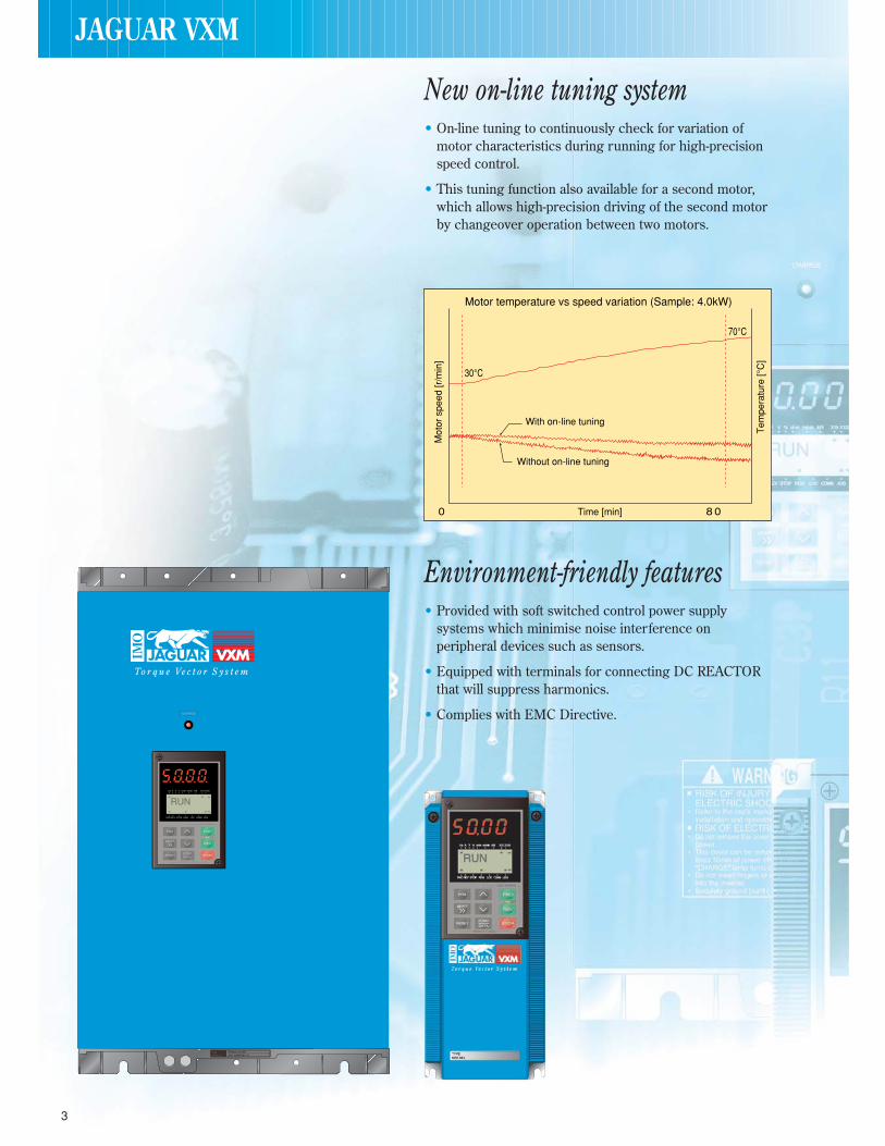
New on-line tuning system• On-line tuning to continuously check for variation of
motor characteristics during running for high-precisionspeed control.
• This tuning function also available for a second motor,which allows high-precision driving of the second motorby changeover operation between two motors.
Environment-friendly features• Provided with soft switched control power supply
systems which minimise noise interference onperipheral devices such as sensors.
• Equipped with terminals for connecting DC REACTORthat will suppress harmonics.
• Complies with EMC Directive.
30°C
70°C
8 00
Mot
or s
peed
[r/m
in]
Time [min]
Motor temperature vs speed variation (Sample: 4.0kW)
Tem
pera
ture
[°C
]
With on-line tuning
Without on-line tuning
JAGUAR VXM
RUNRUN
3

4
Global products, communication• Conforms to major world safety standards: UL, cUL,
TÜV (up to 22kW), CE marked for EMC + LVDcompliance.
• Equipped with RS485 interface as standard.
• Connection to field bus: Profibus-DP, Interbus-S,DeviceNet, Modbus Plus (Option).
• Universal DI/DO: Monitors digital I/O signal status andtransmits to a host controller, helping to simplify factoryautomation.
Power source
Motor speed [r/min]
Output current [A]
Time
Rotating motor pick-up control characteristics (Sample: 4.0kW)
Damper control
Energysaved
Inverter control(V / f control)
Inverter control(Automatic energy-saving control)
Flow rate [%]
Energy saving effect
0
100
100
Req
uire
d po
wer
[%]
Advanced, convenient functions• 16-step speed, 7 pattern operation with timer control, rotating
motor pick-up control for conveyance machinery.
• PID control, cooling fan on/off control, line/inverterchangeover operation for fans and pumps.
• Rotating motor pick-up control:Restarts motor without any shocks, by detecting motor speedwhere motor is coasting after momentary power failure occurs.
• Automatic energy-saving operation function:Minimises inverter and motor loss at light load.
JAGUAR VXM

5
Model numbers and range Jaguar VXM can beEasy to apply to customer systems. A consistent design concept in all modelsfrom 0.4kW to 315kW.
Nominal appliedmotors (kW)
400V series
Constant TorqueRating (CT)
Variable TorqueRating (VT)
0.4
0.75
1.5
2.2
4.0
5.5
7.5
11
15
18.5
22
30
37
45
55
75
90
110
132
160
200
220
280
315
400
VXM40
VXM75
VXM150
VXM220
VXM400
VXM550
VXM750
VXM1100
VXM1500
VXM1850
VXM2200G
VXM30K
VXM37K
VXM45K
VXM55K
VXM75K
VXM90K
VXM110K
VXM132K
VXM160K
VXM200K
VXM220K
VXM280K
VXM315K
VXM550
VXM750
VXM1100
VXM1500
VXM1850
VXM30KP
VXM30K
VXM37K
VXM45K
VXM55K
VXM75K
VXM90K
VXM110K
VXM132K
VXM160K
VXM200K
VXM220K
VXM280K
VXM315K
* : Available soon
How to read the model numberJAGUAR *VX
Family
Type
M 1500
CE marked for EMC + LVdirectives
Standard rating
Terminator
Standard rating examples
40 = 0.4kW150 = 1.5kW
1500 = 15kW
Terminators “*”
No letter = Standard rating appliesK = Rating is in actual kWKP = As K but for fans + pumps onlyG = Cannot be used for higher power than rated
Fans
• Air-conditioning systems (forfactory, building, office, hospital,clean room, supermarkets andfarms)
• Dryers
• Boiler fans
• Fans for controlling furnacetemperature
• Roof fans controlled as a group
• Refrigeration
• Compressors
• Built-in blowers in film-manufacturing machines
• Cooling-tower fans
• Ventilating fans
Food processing machines
• Food mixing machines
• Food slicers
• Grain milling machine (bread,cake, noodles)
• Tea making machines
• Rice cleaning machines
RANGE AND APPLICATION
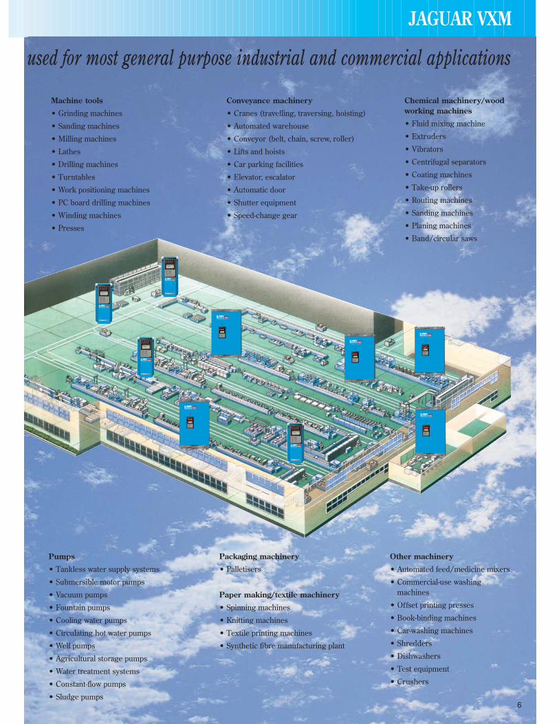
used for most general purpose industrial and commercial applications
Machine tools
• Grinding machines
• Sanding machines
• Milling machines
• Lathes
• Drilling machines
• Turntables
• Work positioning machines
• PC board drilling machines
• Winding machines
• Presses
Conveyance machinery
• Cranes (travelling, traversing, hoisting)
• Automated warehouse
• Conveyor (belt, chain, screw, roller)
• Lifts and hoists
• Car parking facilities
• Elevator, escalator
• Automatic door
• Shutter equipment
• Speed-change gear
Chemical machinery/woodworking machines
• Fluid mixing machine
• Extruders
• Vibrators
• Centrifugal separators
• Coating machines
• Take-up rollers
• Routing machines
• Sanding machines
• Planing machines
• Band/circular saws
Pumps
• Tankless water supply systems
• Submersible motor pumps
• Vacuum pumps
• Fountain pumps
• Cooling water pumps
• Circulating hot water pumps
• Well pumps
• Agricultural storage pumps
• Water treatment systems
• Constant-flow pumps
• Sludge pumps
Packaging machinery
• Palletisers
Paper making/textile machinery
• Spinning machines
• Knitting machines
• Textile printing machines
• Synthetic fibre manufacturing plant
Other machinery
• Automated feed/medicine mixers
• Commercial-use washingmachines
• Offset printing presses
• Book-binding machines
• Car-washing machines
• Shredders
• Dishwashers
• Test equipment
• Crushers
JAGUAR VXM
RUNRUN
RUNRUN
RUNRUN
RUNRUN
RUNRUN
6

7
Intelligent keypad panel• Copy function: Easily copies function codes and data
to other inverters.
• Six languages (English, French, German, Italian,Spanish and Japanese) are available as standard.
• Jogging (inching) operation from the Keypad orexternal signal.
• Remote operation using optional extension cable(VXM podcable).
Protective functions,maintenanceProtection
• Motors with various characteristics can be used bysetting thermal time constant for the electronicthermal overload relay.
• Input phase loss protective function protects theinverter from damage caused by disconnection ofpower supply lines.
• Motor is protected with a PTC thermistor.
• Input terminals for auxiliary control power supply(1.5kW or larger models): Alarm signal output willbe held even if main circuit power supply has shut down.
Maintainability
The items below can be monitored on the Keypadpanel, making it easy to analyse the cause of trip andto take preventive measures.
• Input/output terminals check
• Life expectancy of main-circuit capacitors
• Inverter on-load factor
• Accumulated operation time
• Inverter operating condition (output current, heatsink temperature, input power, etc)
• Detailed data on trip cause.
Extensive product line• Since the product is equipped with a dual rating
feature, it can be used for variable torque ratingcontrol (VT) (5.5kW or larger), as well as constanttorque rating (CT].
The variable torque rating can be used for one-classhigher than the constant torque rating.*For 30kW only, the model numbers for the VT rating and CT ratingare different.
• Totally-enclosed casing (IP40) (up to 22kW as standard).
• Optional IP20 enclosure available for 30kW or larger models.
• Waterproof models (IP65 for 7.5kW or smaller, IP54for 11 to 22kW) as a separate series (available soon).
Other useful functions• Side-by-side mounting (up to 22kW) saves space
when inverters are installed in a panel.
• The uniform height (260mm) of products (up to 7.5kW) makes it easy to design panels.
• User-definable control terminals: Digital input (9 points), transistor output (4 points) and relaycontact output (1 point).
• Active drive feature: Performs prolongedacceleration at reduced torque, monitoring the loadstatus to prevent tripping.
• Stall prevention function is provided as standard.Active or inactive can be also selected.
The above torque characteristics depend on the motorcharacteristics.
200
10090
50
1 6 1520 50 100
Torque characteristics with Dynamic torque-vector control
100% of output torque refers to the rated torque of the motordriven at 50Hz.
Short time operation torqueContinuous operation torque
0.4 to 1.5kW
2.2 to 22kW
Output frequency [Hz]
Out
put t
orqu
e [%
]
JAGUAR VXM
JAGUAR VXM
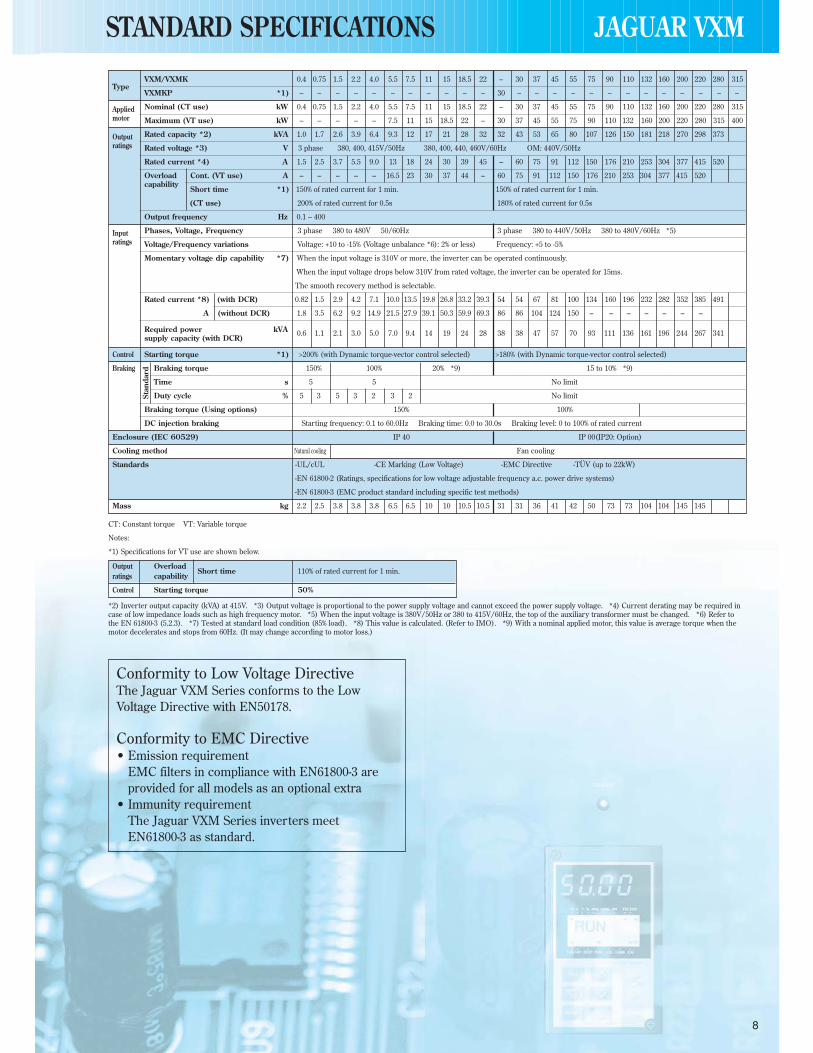
VXM/VXMK 0.4 0.75 1.5 2.2 4.0 5.5 7.5 11 15 18.5 22 – 30 37 45 55 75 90 110 132 160 200 220 280 315Type
VXMKP *1) – – – – – – – – – – – 30 – – – – – – – – – – – – –
Applied Nominal (CT use) kW 0.4 0.75 1.5 2.2 4.0 5.5 7.5 11 15 18.5 22 – 30 37 45 55 75 90 110 132 160 200 220 280 315motor Maximum (VT use) kW – – – – – 7.5 11 15 18.5 22 – 30 37 45 55 75 90 110 132 160 200 220 280 315 400
Output Rated capacity *2) kVA 1.0 1.7 2.6 3.9 6.4 9.3 12 17 21 28 32 32 43 53 65 80 107 126 150 181 218 270 298 373 ratings Rated voltage *3) V 3 phase 380, 400, 415V/50Hz 380, 400, 440, 460V/60Hz OM: 440V/50Hz
Rated current *4) A 1.5 2.5 3.7 5.5 9.0 13 18 24 30 39 45 – 60 75 91 112 150 176 210 253 304 377 415 520
Overload Cont. (VT use) A – – – – – 16.5 23 30 37 44 – 60 75 91 112 150 176 210 253 304 377 415 520 capability
Short time *1) 150% of rated current for 1 min. 150% of rated current for 1 min.
(CT use) 200% of rated current for 0.5s 180% of rated current for 0.5s
Output frequency Hz 0.1 – 400
Input Phases, Voltage, Frequency 3 phase 380 to 480V 50/60Hz 3 phase 380 to 440V/50Hz 380 to 480V/60Hz *5)ratings Voltage/Frequency variations Voltage: +10 to -15% (Voltage unbalance *6): 2% or less) Frequency: +5 to -5%
Momentary voltage dip capability *7) When the input voltage is 310V or more, the inverter can be operated continuously.
When the input voltage drops below 310V from rated voltage, the inverter can be operated for 15ms.
The smooth recovery method is selectable.
Rated current *8) (with DCR) 0.82 1.5 2.9 4.2 7.1 10.0 13.5 19.8 26.8 33.2 39.3 54 54 67 81 100 134 160 196 232 282 352 385 491
A (without DCR) 1.8 3.5 6.2 9.2 14.9 21.5 27.9 39.1 50.3 59.9 69.3 86 86 104 124 150 – – – – – – –
Required power kVA 0.6 1.1 2.1 3.0 5.0 7.0 9.4 14 19 24 28 38 38 47 57 70 93 111 136 161 196 244 267 341 supply capacity (with DCR)
Control Starting torque *1) >200% (with Dynamic torque-vector control selected) >180% (with Dynamic torque-vector control selected)
Braking Braking torque 150% 100% 20% *9) 15 to 10% *9)
Time s 5 5 No limit
Duty cycle % 5 3 5 3 2 3 2 No limit
Braking torque (Using options) 150% 100%
DC injection braking Starting frequency: 0.1 to 60.0Hz Braking time: 0.0 to 30.0s Braking level: 0 to 100% of rated current
Enclosure (IEC 60529) IP 40 IP 00(IP20: Option)
Cooling method Natural cooling Fan cooling
Standards -UL/cUL -CE Marking (Low Voltage) -EMC Directive -TÜV (up to 22kW)
-EN 61800-2 (Ratings, specifications for low voltage adjustable frequency a.c. power drive systems)
-EN 61800-3 (EMC product standard including specific test methods)
Mass kg 2.2 2.5 3.8 3.8 3.8 6.5 6.5 10 10 10.5 10.5 31 31 36 41 42 50 73 73 104 104 145 145
Stan
dard
CT: Constant torque VT: Variable torque
Notes:
*1) Specifications for VT use are shown below.
*2) Inverter output capacity (kVA) at 415V. *3) Output voltage is proportional to the power supply voltage and cannot exceed the power supply voltage. *4) Current derating may be required incase of low impedance loads such as high frequency motor. *5) When the input voltage is 380V/50Hz or 380 to 415V/60Hz, the top of the auxiliary transformer must be changed. *6) Refer tothe EN 61800-3 (5.2.3). *7) Tested at standard load condition (85% load). *8) This value is calculated. (Refer to IMO). *9) With a nominal applied motor, this value is average torque when themotor decelerates and stops from 60Hz. (It may change according to motor loss.)
Output OverloadShort time 110% of rated current for 1 min.
ratings capability
Control Starting torque 50%
Conformity to Low Voltage DirectiveThe Jaguar VXM Series conforms to the Low Voltage Directive with EN50178.
Conformity to EMC Directive• Emission requirement
EMC filters in compliance with EN61800-3 are provided for all models as an optional extra
• Immunity requirementThe Jaguar VXM Series inverters meet EN61800-3 as standard.
8
STANDARD SPECIFICATIONS

9
Item Explanation
Output Maximum frequency 50 to 400Hz *1)frequency Base frequency 25 to 400Hz *1)
Starting frequency 0.2 to 60Hz, Holding time: 0.0 to 10.0s
Carrier frequency *2) CT use VT use0.75 to 15kHz (55kW or smaller) *3) 0.75 to 15kHz (22kW or smaller)0.75 to 10kHz (75kW or larger) 0.75 to 10kHz (30 to 75kW)
0.75 to 6kHz (90kW or larger)
Accuracy (Stability) • Analog setting : ±0.2% of maximum frequency (at 25 ±10˚C)• Digital setting : ±0.01% of maximum frequency (at -10 to +50˚C)
Setting resolution • Analog setting : 1/3000 of maximum frequency ex.) 0.02Hz at 60Hz, 0.04Hz at 120Hz, (0.15Hz at 400Hz : EN)• Digital setting : 0.01Hz at maximum frequency of up to 99.99Hz (0.1Hz at Maximum frequency of 100Hz and above)• LINK setting : 1/20000 of maximum frequency ex.) 0.003Hz at 60Hz, 0.006Hz at 120Hz, (0.02Hz at 400Hz : EN) • 0.01Hz (Fixed)
Control Control method • V/f control (Sinusoidal PWM control) • Dynamic torque-vector control (Sinusoidal PWM control) • Vector control with PG (*) (EN only)
Voltage/freq. (V/f) characteristic Adjustable at base and maximum frequency, with AVR control : 320 to 480V
Torque boost Selectable by load characteristics: Constant torque load (Auto/manual), variable torque (manual)
Operation method • KEYPAD operation : or key, key
• Digital input signal operation : FWD or REV command, Coast-to-stop command, etc.
• LINK operation : RS485 (Standard)Profibus-DP, Interbus-S, DeviceNet, Modbus Plus, CAN open (Option)
Frequency setting • KEYPAD operation : or key
(Frequency command) • External potentiometer (*) : 1 to 5k (1/2W)
• Analog input : 0 to +10VDC (0 to +5VDC), 4 to 20mA DC(Reversible 0 to ±10VDC (0 to ±5VDC) . . . Reversible operation by polarised signal can be selected.
(Inverse) +10 to 0VDC, 20 to 4mA DC . . . Inverse mode operation can be selected.
• UP/DOWN control : Output frequency increases when UP signal is ON, and decreases when DOWN signal is ON.
• Multistep frequency : Up to 16 different frequencies can be selected by digital input signal.
• Pulse train input (*) : 0 to 100kp/s
• Digital signal (parallel) (*) : 16-bit binary
• LINK operation : RS485 (Standard)• Profibus-DP, Interbus-S, DeviceNet, Modbus Plus, CAN open (Option)
• Programmed PATTERN operation: Maximum 7 stages
Jogging operation • or key, FWD or REV digital input signal
Running status signal Transistor output (4 points) : RUN, FAR, FDT, OL, LU, TL, etc.
Relay output (2 points) : Same as transistor output • Alarm output (for any fault)
Analog output (1 point) : Output frequency, output current, output torque, etc.
Pulse output (1 point) : Output frequency, output current, output torque, etc.
Acceleration/Deceleration time 0.01 to 3600s : Independently adjustable acceleration and deceleration • 4 different times are selectable.
Mode select : Linear, S-curve (weak), S-curve (strong), Non-linear
Active drive When the acceleration time reaches 60s, the motor output torque is automatically reduced to rated torque.After 60s the motor operation mode is changed to torque limiting operation.The acceleration time is automatically extended up to 3 times.
Frequency limiter High and low limiter can be preset.
Bias frequency Bias frequency can be preset.
Gain for frequency setting Gain for frequency setting can be preset (0.0 to 200.0%) ex.) Analog input 0 to +5VDC with 200% gain results in maximum frequency at 5VDC.
Skip frequency control Skip frequency (3 points) and its common skip hysteresis width (0 to 30Hz) can be preset.
Rotating motor pick up (Flying start) A rotating motor (including inverse rotating mode) can be smoothly picked up without stopping the motor (speed search method).
Auto-restart after momentary power Automatic restart is available without stopping motor after a momentary power failure (speed search method). When “Smooth recovery” mode isfailure selected, the motor speed drop is held minimum. (The inverter searches the motor speed and smoothly returns to setting frequency.)
Line/Inverter changeover operation Controls the switching operation between line power and inverter. The inverter has internal sequence function.
Slip compensation The inverter output frequency is controlled according to the load torque to keep motor speed constant. When the valueis set at “0.00” and “Torque-vector” is set at “active”, the compensation value is automatically set.
Slip compensation can be preset for the second motor.
Droop operation The motor speed droops in proportional to output torque (-9.9 to 0.0Hz).
Torque limiting • When the motor torque reaches a preset limiting level, this function automatically adjusts the output frequency to prevent the inverter from tripping due to an overcurrent. • Torque limiting 1 and 2 can be individually set, and are selectable with a digital input signal.
Torque control Output torque (or load factor) can be controlled with an analog input signal.
PID control This function can control flow rate pressure, etc. (with an analog feedback signal.)• Reference • KEYPAD operation ( or key): Setting freq./Max. freq. X 100 (%) • PATTERN operation : Setting freq./Max. freq. X 100 (%)
signal • Voltage input (Terminal 12 and V2) : 0 to +10V DC • DI option input (*) : BCD, setting freq./Max. freq. X 100 (%)• Current input (Terminal C1) : 4 to 20mA DC • Binary, full scale/100 (%)• Reversible operation with polarity (Terminal 12) : 0 to ±10V DC • Multistep frequency setting : Setting freq./Max freq. X 100 (%)• Reversible operation with polarity (Terminal 12 + V1) : 0 to ±10V DC • RS485 : Setting freq./Max freq. X 100 (%)• Inverse mode operation (Terminal 12 and V2) : +10 to 0V DC• Inverse mode operation (Terminal C1) : 20 to 4mA DC
• Feedback • Terminal 12 (0 to +10V DC or +10 to 0V DC)signal • Terminal C1 (4 to 20mA DC or 20 to 4mA DC)
Sett
ing
NOTES: (*) Option*1) For application at 120Hz or above, please contact IMO.*2) Inverter may automatically reduce carrier frequency, in accordance with ambient temperature or output current for protection purposes.*3) The minimum carrier frequency changes depending on maximum output frequency.
COMMON SPECIFICATIONS
10
JAGUAR VXM
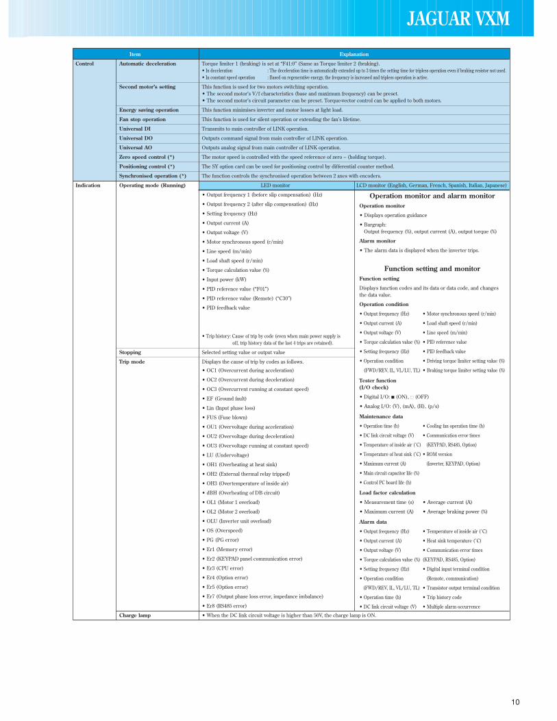
Item Explanation
Control Automatic deceleration Torque limiter 1 (braking) is set at “F41:0” (Same as Torque limiter 2 (braking).• In deceleration : The deceleration time is automatically extended up to 3 times the setting time for tripless operation even if braking resistor not used.• In constant speed operation : Based on regenerative energy, the frequency is increased and tripless operation is active.
Second motor’s setting This function is used for two motors switching operation.• The second motor’s V/f characteristics (base and maximum frequency) can be preset.• The second motor’s circuit parameter can be preset. Torque-vector control can be applied to both motors.
Energy saving operation This function minimises inverter and motor losses at light load.
Fan stop operation This function is used for silent operation or extending the fan’s lifetime.
Universal DI Transmits to main controller of LINK operation.
Universal DO Outputs command signal from main controller of LINK operation.
Universal AO Outputs analog signal from main controller of LINK operation.
Zero speed control (*) The motor speed is controlled with the speed reference of zero – (holding torque).
Positioning control (*) The SY option card can be used for positioning control by differential counter method.
Synchronised operation (*) The function controls the synchronised operation between 2 axes with encoders.
Indication Operating mode (Running) LED monitor LCD monitor (English, German, French, Spanish, Italian, Japanese)
• Output frequency 1 (before slip compensation) (Hz)
• Output frequency 2 (after slip compensation) (Hz)
• Setting frequency (Hz)
• Output current (A)
• Output voltage (V)
• Motor synchronous speed (r/min)
• Line speed (m/min)
• Load shaft speed (r/min)
• Torque calculation value (%)
• Input power (kW)
• PID reference value (“F01”)
• PID reference value (Remote) (“C30”)
• PID feedback value
• Trip history: Cause of trip by code (even when main power supply is off, trip history data of the last 4 trips are retained).
Stopping Selected setting value or output value
Trip mode Displays the cause of trip by codes as follows.
• OC1 (Overcurrent during acceleration)
• OC2 (Overcurrent during deceleration)
• OC3 (Overcurrent running at constant speed)
• EF (Ground fault)
• Lin (Input phase loss)
• FUS (Fuse blown)
• OU1 (Overvoltage during acceleration)
• OU2 (Overvoltage during deceleration)
• OU3 (Overvoltage running at constant speed)
• LU (Undervoltage)
• OH1 (Overheating at heat sink)
• OH2 (External thermal relay tripped)
• OH3 (Overtemperature of inside air)
• dBH (Overheating of DB circuit)
• OL1 (Motor 1 overload)
• OL2 (Motor 2 overload)
• OLU (Inverter unit overload)
• OS (Overspeed)
• PG (PG error)
• Er1 (Memory error)
• Er2 (KEYPAD panel communication error)
• Er3 (CPU error)
• Er4 (Option error)
• Er5 (Option error)
• Er7 (Output phase loss error, impedance imbalance)
• Er8 (RS485 error)
Charge lamp • When the DC link circuit voltage is higher than 50V, the charge lamp is ON.
Operation monitor and alarm monitorOperation monitor
• Displays operation guidance
• Bargraph: Output frequency (%), output current (A), output torque (%)
Alarm monitor
• The alarm data is displayed when the inverter trips.
Function setting and monitorFunction setting
Displays function codes and its data or data code, and changes the data value.
Operation condition
• Output frequency (Hz) • Motor synchronous speed (r/min)
• Output current (A) • Load shaft speed (r/min)
• Output voltage (V) • Line speed (m/min)
• Torque calculation value (%) • PID reference value
• Setting frequency (Hz) • PID feedback value
• Operation condition • Driving torque limiter setting value (%)
(FWD/REV, IL, VL/LU, TL) • Braking torque limiter setting value (%)
Tester function(I/O check)
• Digital I/O: (ON), (OFF)
• Analog I/O: (V), (mA), (H), (p/s)
Maintenance data
• Operation time (h) • Cooling fan operation time (h)
• DC link circuit voltage (V) • Communication error times
• Temperature of inside air (˚C) (KEYPAD, RS485, Option)
• Temperature of heat sink (˚C) • ROM version
• Maximum current (A) (Inverter, KEYPAD, Option)
• Main circuit capacitor life (%)
• Control PC board life (h)
Load factor calculation
• Measurement time (s) • Average current (A)
• Maximum current (A) • Average braking power (%)
Alarm data
• Output frequency (Hz) • Temperature of inside air (˚C)
• Output current (A) • Heat sink temperature (˚C)
• Output voltage (V) • Communication error times
• Torque calculation value (%) (KEYPAD, RS485, Option)
• Setting frequency (Hz) • Digital input terminal condition
• Operation condition (Remote, communication)
(FWD/REV, IL, VL/LU, TL) • Transistor output terminal condition
• Operation time (h) • Trip history code
• DC link circuit voltage (V) • Multiple alarm occurrence

11
Item Explanation
Protection Overload Protects the inverter by electronic thermal and detection of inverter temperature.
Overvoltage Detects DC link circuit overvoltage, and stops the inverter. 400V series: 800VDC.
Undervoltage Detects DC link circuit undervoltage, and stops the inverter. 400V series: 400VDC.
Input phase loss Phase loss protection for power line input.
Overheating Protects the inverter by detection of inverter temperature.
Short-circuit Short-circuit protection for inverter output circuit.
Ground fault • Ground fault protection for inverter output circuit (3 phase current detection method).• Zero-phase current detection method (30kW or larger).
Motor overload • Electronic thermal overload relay can be selected for standard motor or inverter rated motor.• Thermal time constant (0.5 to 75.0 minutes) can be preset for a special motor.• The second motor’s electronic thermal overload relay can be preset for 2-motor changeover operation.
DB resistor overheating • Prevents DB resistor overheating by internal electronic thermal overload relay (7.5kW or smaller).• Prevents DB resistor overheating by external thermal overload relay attached to DB resistor (11kW or larger).(The inverter stops discharge operation to protect the DB resistor).
Stall prevention • Controls the output frequency to prevent (overcurrent) trip when the output current exceeds the limit value during acceleration.• Lowers the output frequency to hold almost constant torque when the output current exceeds the limit value during operation at constant speed.• Controls the output frequency to prevent (overvoltage) trip when the DC link circuit voltage exceeds the limit value during deceleration.
Output phase loss When the inverter executes auto-tuning, detects each phase impedance imbalance and displays an Error code.
Motor protection by PTC thermistor When the motor temperature exceeds allowable value, the inverter trips automatically.
Auto reset When the inverter is tripped it can be set to automatically reset and start.
Condition Installation location Free from corrosive gases, flammable gases, oil mist, dusts and direct sunlight. Indoor use only.(Installation Altitude 1000m or less. Applicable to 3000m with power derating (-10%/1000m).and
Ambient temperature -10 to +50˚C. For inverters of 22kW or smaller, remove the ventilation covers when operating it at a temperature of 40˚C or above.operation)Ambient humidity 5 to 95%RH (non-condensing).
Vibration 3mm from 2 to less than 9Hz, 9.8m/s2 from 9 to less than 20Hz2m/s2 from 20 to less than 55Hz, 1m/s2 from 55 to less than 200Hz
Storage condition Temperature: -25 to +65˚C, Humidity: 5 to 95%RH (non-condensing)
JAGUAR VXM

JAGUAR VXM
12
Symbol Terminal name Function Remarks Func. code
Main L1/R, L2/S, Power input Connect a 3 phase power supplycircuit L3/T
U, V, W Inverter output Connect a 3 phase induction motorP1, P(+) For DC REACTOR Connect the DC REACTOR for power-factor correcting or harmonic current reducing DC REACTOR: Option
P(+), N(-) For BRAKING UNIT• Connect the BRAKING UNIT (option) BRAKING UNIT (Option): 11kW or largerUsed for DC bus connection system
P(+), DBFor EXTERNAL
Connect the EXTERNAL BRAKING RESISTOR (option) Only for 7.5kW or smallerBRAKING RESISTORG Grounding Ground terminal for inverter chassis (housing)
R0, T0 Auxiliary control Connect the same AC power supply as that of the main circuit to back up the control0.75kW or smaller: Not applicablepower supply circuit power supply
Analog 13 Potentiometer+10VDC power supply for frequency setting POT (POT: 1 to 5kΩ) • Allowable maximum output current: 10mAinput power supply
12 Voltage input • 0 to +10VDC/0 to 100% (0 to +5VDC/0 to 100%) • Input impedance: 22kΩ F01, C30• Reversible operation can be selected by function setting. • Allowable maximum input voltage: ±15VDC
0 to ±10VDC/0 to ±100% (0 to ±5VDC/0 to ±100%) • If input voltage is 10 to 15VDC, the inverter • Inverse mode operation can be selected by function setting or digital input signal estimates it to 10VDC
+10 to 0VDC/0 to 100%(Torque control) Used for torque control reference signal H18
(PID control) Used for PID control reference signal or feedback signal F01, H21(PG feedback) Used for reference signal of PG feedback control (option)
C1 Current input • 4 to 20mA DC/0 to 100% • Input impedance: 250kΩ• Inverse mode operation can be selected by function setting or digital input signal. • Allowable maximum input current: 30mA DC
20 to 4mA DC/0 to 100% • If input current is 20 to 30mA DC, the inverter estimates it to 20mA DC
(PID control) Used for PID control reference signal or feedback signal F01, H21(PTC-Thermistor input) The PTC-thermistor (for motor protection) can be connected to terminal C1-11 Change over the PIN switch on control board (SW2: PTC) H26, H27
V2 Voltage input 2 0 to +10VDC Can’t change over the terminal C1 F0111 Common Common for analog signal Isolated from terminal CMY and CM
Digital FWD Forward operation FWD: ON . . . The motor runs in the forward direction When FWD and REV are simultaneously ON, the F02input command FWD: OFF . . . The motor decelerates and stops decelerates and stops
REV Reverse operation REV: ON . . . The motor runs in the reverse directioncommand REV: OFF . . . The motor decelerates and stops
X1 Digital input 1 These terminals can be preset as follows • ON state maximum input voltage: 2V E01 to E09X2 Digital input 2 (maximum source current: 5mA)X3 Digital input 3 • OFF state maximum terminal voltage: 22 to 27V
X4 Digital input 4(allowable maximum leakage current: 0.5mA)
X5 Digital input 5X6 Digital input 6X7 Digital input 7X8 Digital input 8X9 Digital input 9
(SS1) Multistep freq. (SS1) : 2 (0,1) different frequencies are selectable Frequency 0 is set by F01 (or C30) C05 to C19(SS2) selection (SS1, SS2) : 4 (0 to 3) different frequencies are selectable (All signals of SS1 to SS8 are OFF)(SS4) (SS1, SS2, SS4) : 8 (0 to 7) different frequencies are selectable(SS8) (SS1, SS2, SS4, SS8) : 16 (0 to 15) different frequencies are selectable(RT1) ACC/DEC time selection (RT1 : 2 (0, 1) different ACC/DEC times are selectable Time 0 is set by F07/F08 F07, F08(RT2) (RT1, RT2) : 4 (0 to 3) different ACC/DEC times are selectable (All signals of RT1 to RT2 are OFF) E10 to E15(HLD) 3 wire operation Used for 3 wire operation Assigned to terminal X7 at factory setting
stop command (HLD): ON . . . The inverter self-holds FWD or REV signal(HLD): OFF . . . The inverter releases self-holding
(BX) Coast-to-stop (BX): ON . . . Motor will coast-to-stop. (No alarm signal will be output) • The motor restarts from 0Hz by turning off BX H11command with the operation command (FWD or REV) ON
• Assigned to terminal X8 at factory setting(RST) Alarm reset (RST): ON . . . Faults are reset. (This signal should be held for more than 0.1s) • During normal operating, this signal is ignored
• Assigned to X9 at factory setting
(THR)Trip command
(THR): OFF . . . “OH2 trip” occurs and motor will coast-to-stop This alarm signal is held internally(External fault)(JOG) Jogging operation (JOG): ON . . . JOG frequency is effective This signal is effective only while the inverter is stopped C20
(Hz2/Hz1) Freq. set 2/Freq. set 1 (Hz2/Hz1): ON . . . Freq. set 2 is effectiveIf this signal is changed while the inverter is running C30/F01the signal is effective only after the inverter stops
(M2/M1) Motor 2/Motor 1 (M2/M1): ON . . . The motor circuit parameter and V/f characteristics are changed If this signal is changed while the inverter is running A10 to A18/to the second motor’s ones the signal is effective only after the inverter stops P01 to P09
(DCBRK) DC brake command(DCBRK): ON . . . The DC injection brake is effective. (In the inverter If the operation command (FWD/REV) is input while DC braking F20 to F22
deceleration mode) is effective, the operation command (FWD/REV) has priority
(TL2/TL1)Torque limiter 2/
(TL2/TL1): ON . . . Torque limiter 2 is effectiveE16, E17/
Torque limiter 1 F40, F41(SW50) Switching operation (SW50(SW60)): ON . . . The motor is changed from inverter operation to line operation Main circuit changeover signals are output through(SW60) between line and inverter (SW50(SW60)): OFF . . . The motor is changed from line operation to inverter operation Y1 to Y5 terminal
(UP) UP command (UP): ON . . . The output frequency increases When UP and DOWN commands are simultaneously(DOWN) DOWN command (DOWN): ON . . . The output frequency decreases ON, DOWN signal is effective
• The output frequency change rate is determined by ACC/DEC time• Restarting frequency can be selected from 0Hz or setting value at the time of stop F01, C30
(WE-KP) Write enable for KEYPAD (WE-KP): ON . . . The data is changed by KEYPAD F00(Hz/PID) PID control cancel (Hz/PID): ON . . . The PID control is cancelled, and frequency setting by KEYPAD H20 to H25
( or ) is effective(IVS) Inverse mode changeover (IVS): ON . . . Inverse mode is effective in analog signal input If this signal is changed while the inverter is running F01, C30
the signal is effective only after the inverter stops(IL) Interlock signal for 52-2 Connect to auxiliary contact (1NC) of 52-2
(Hz/TRQ) TRQ control cancel (Hz/TRQ): ON . . . The torque control is cancelled, and ordinary operation is effective H18(LE) Link enable (RS485, Bus) (LE): ON . . . The link operation is effective. Used to switch between manual RS485: Standard, Bus: option H30
operation and serial link auto mode(U-DI) Universal DI This signal is transmitted to main controller of LINK operation(STM) Pick up start mode (STM): ON . . . The “Pick up” start mode is effective H09
(PG/Hz) SY-PG enabled (PG/Hz): ON . . . Synchronised operation or PG-feedback operation is effective Option(SYC) Synchronised command (SYC): ON . . . The motor is controlled for synchronised operation between 2 axes with PGs Option
(ZERO) Zero speed command (ZERO): ON . . . The motor speed is controlled with the speed reference of zero This function can be selected at PG feedback control. Option(STOP 1) Forced stop command (STOP 1): OFF . . . The motor decelerates and stops(STOP 2) Forced stop command (STOP 2): OFF . . . The motor decelerates and stops with Deceleration time 4 E15
with Deceleration time 4(EXITE) Pre-exciting command (EXITE): ON . . . Motor magnetic flux is established before starting in PG vector mode
PLC PLC terminal Connect PLC power supply to avoid malfunction of the inverter that has SINK typedigital input, when PLC power supply is off
P24 DC voltage supply DC voltage supply (+24V, maximum 100mA)
TERMINAL FUNCTIONS
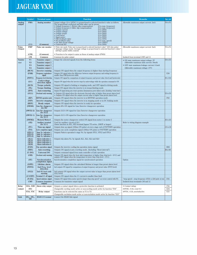
Symbol Terminal name Function Remarks Func. code
Analog FMA Analog monitor Output voltage (0 to 10VDC) is proportional to selected function’s value as follows. Allowable maximum output current: 2mA F30 to F31output The proportional coefficient and bias value can be preset.
• Output frequency 1 (Before slip compensation) (0 to max. frequency)• Output frequency 2 (After slip compensation) (0 to max. frequency)• Output current (0 to 200%)• Output voltage (0 to 200%)• Output torque (0 to 200%)• Load factor (0 to 200%)• Input power (0 to 200%)• PID feedback value (0 to 100%)• PG feedback value (0 to max. speed)• DC link circuit voltage (0 to 1000V)
(11) (Common) • Universal AO (0 to 100%)Pulse FMP Pulse rate monitor • Pulse rate mode: Pulse rate is proportional to selected function’s value* (50% duty pulse) Allowable maximum output current: 2mA F33 to F35Output • Average voltage mode: Average voltage is proportional to selected function’s value*
(2670p/s pulse width control)
(CM) (Common) • Function to be output is same as those of analog output (FMA)CM Common Common for pulse output Isolated from terminal CMY and 11
Transistor Y1 Transistor output 1 Output the selected signals from the following items • ON state maximum output voltage: 3V E20 to E23output Y2 Transistor output 2 (Allowable maximum sink current: 50mA)
Y3 Transistor output 3 • OFF state maximum leakage current: 0.1mAY4 Transistor output 4 (Allowable maximum voltage: 27V)
(RUN) Inverter running Outputs ON signal when the output frequency is higher than starting frequency(FAR) Frequency equivalence Outputs ON signal when the difference between output frequency and setting frequency is E30
signal smaller than FAR hysteresis width(FDT1) Frequency level detection Outputs ON signal by comparison of output frequency and preset value (level and hysteresis) E31, E32
Undervoltage(LU) Outputs ON signal when the inverter stops by undervoltage while the operation command is ON.detection signal(B/D) Torque polarity Outputs ON signal in braking or stopping mode, and OFF signal in driving mode(TL) Torque limiting Output ON signal when the inverter is in torque-limiting mode(IPF) Auto-restarting Outputs ON signal during auto restart operation (Instantaneous power failure) mode. (Including “restart time”)(OL1) Overload early warning • Outputs ON signal when the electronic thermal value is higher than preset alarm level E33 to E35
• Outputs ON signal when the output current value is higher than preset alarm level(KP) KEYPAD operation mode Outputs ON signal when the inverter is in KEYPAD operation mode F02(STP) Inverter stopping Outputs ON signal when the inverter is in stopping mode or in DC braking mode(RDY) Ready output Outputs ON signal when the inverter is ready for operation
(SW88) Line/Inv changeover Outputs 88’s ON signal for Line/Inverter changeover operation(for 88)
(SW52-2) Line/Inv changeover Outputs 52-2’s ON signal for Line/Inverter changeover operation(for 52-2)
(SW52-1) Line/Inv changeover Outputs 52-1’s ON signal for Line/Inverter changeover operation(for 52-1)
(SWM2) Motor2/Motor1 Outputs the motor changeover switch ON signal from motor 1 to motor 2 A01 to A18(AX) Auxiliary terminal Used for auxiliary circuit of 52-1 Refer to wiring diagram example
(for 52-1) (Same function as AX1, AX2 terminal Jaguar VX series. (30kW or larger)(TU) Time-up signal Outputs time up signal (100ms ON pulse) at every stage end of PATTERN operation C21 to C28(TO) Cycle completion signal Outputs one cycle completion signal (100ms ON pulse) at PATTERN operation
(STG1) Stage No. indication 1 Outputs Pattern operation’s stage No. by signals STG1, STG2 and STG4(STG2) Stage No. indication 2(STG4) Stage No. indication 4(AL1) Alarm indication 1 Outputs trip alarm No. by signals AL1, AL2, AL4 and AL8(AL2) Alarm indication 2(AL4) Alarm indication 4(AL8) Alarm indication 8(FAN) Fan operation signal Outputs the inverter cooling fan operation status signal H06(TRY) Auto-resetting Outputs ON signal at auto resetting mode. (Including “Reset interval”) H04, H05
(U-DO) Universal DO Outputs command signal from main controller of Link operation(OH) Overheat early warning Outputs ON signal when the heat sink temperature is higher than (trip level – 10˚C) and
outputs OFF signal when the temperature is lower than (trip level – 15˚C)(SY) Synchronisation Synchronisation completion signal for synchronised operation Option
completion signal(LIFE) Lifetime alarm Outputs ON signal when the calculated lifetime is longer than preset alarm level(FDT2) 2nd Freq. level 2nd outputs ON signal by comparison of output frequency and preset value (FDT2 level)
detection(OL2) 2nd OL level early 2nd outputs ON signal when the output current value is larger than preset alarm level
warning (OL2 level)(C1OFF) Terminal C1 off signal Outputs ON signal when the C1 current is smaller than 2mA(N-EX) Speed existence signal Outputs ON signal when motor speed is larger than stop speed* on vector control with PG *stop speed = stop frequency (F25) x 120/pole (r/m) F25CMY Common (transistor Common for transistor output signal Isolated from terminals CM and 11
output)Relay 30A, 30B Alarm relay output Outputs a contact signal when a protective function is activated • Contact rating: F36output 30C Changeable exciting mode active or non-exciting mode active by function “F36” 250VAC, 0.3A, cosø=0.3 E24
Y5A, Y5C Relay output Functions can be selected the same as Y1 to Y4 48VDC, 0.5A, non-inductive E25Changeable excitation mode active or non-excitation mode active by function “E25”
Link DX+, DX-, RS485 I/O terminal Connect the RS485 link signalSD
13
JAGUAR VXM
14
JAGUAR VXM
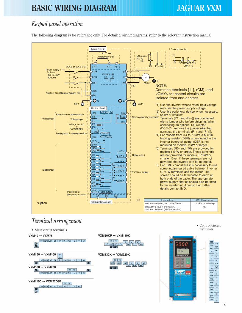
Keypad panel operation
Terminal arrangement
The following diagram is for reference only. For detailed wiring diagrams, refer to the relevant instruction manual.
• Main circuit terminals• Control circuit
terminals
L1/R
L2/S
L3/T
U
V
WG
GG
M
N(-) N(-)
N(-)
P(+) DBRDBP(+)
P1
(R0)
(T0)
(X9)(CM)
(FMP)
(DX-) (DX+) (SD)
(X1)
(PLC)
(P24)
(FWD)
(REV)(CM)
(X8)
< Y5C >< Y5A >
< Y4 >
< Y1 >< Y2 >
< Y3 >
< CMY >
(X7)
(X6)
(X5)
(X4)
(X3)(X2)
0V 30A
30B
30C
30
0V
+DC10V
+DC24V+DC0~10V
[13]
[12]
[11]
[C1]
[FMA]
11 to 55 kW
P(+)P1
P1
MCCB or ELCB ( *2) Power supply ( *1) 3-phase 400 to 480V 50/60Hz
Main circuit
Jumper wire (*3)
(*6)
(*4)
(*3)
Auxiliary control power supply( *5)
Earth Earth
Control circuit
Analog input
Potentiometer power supply
Voltage input
Voltage input 2or
Current input
Analog output (analog monitor)
Digital input
Pulse output (frequency monitor)
*Option RS485 interface port
Pulse output
Motor*
DC reactor (DCR)
Alarm output (for any fault)
Relay output
Transistor output
7.5 kW or smaller
CNUX ( )U1 U2
[V2]
(*6) NOTE:Common terminals [11], (CM), and<CMY> for control circuits areisolated from one another.
*1) Use the inverter whose rated input voltagematches the power supply voltage.
*2) Use this peripheral device when necessary.*3) 55kW or smaller:
Terminals (P1) and (P(+)] are connectedwith a jumper wire before shipping. Whenconnecting an optional DC reactor(DCR)*6), remove the jumper wire thatconnects the terminals (P1) and (P(+)].
*4) For models from 0.4 to 7.5kW, a built-inbraking resistor (DBR) is connected to theinverter before shipping. (DBR is notmounted on models 11kW or larger.)
*5) Terminals (R0) and (T0) are provided formodels 1.5kW or larger. These terminalsare not provided for models 0.75kW orsmaller. Even if these terminals are notpowered, the inverter can be operated.
*6) For EMC compliance it is necessary to usescreened/armoured cable between inverterU, V, W terminals and the motor. The screen should be terminated to earth atboth ends of the cable. The appropriatepower supply filter kit should also be fittedto the inverter input circuit. For furtherdetails contact IMO.
Input voltage CNUX connector
400 to 440V/50Hz, 440 to 480V/60Hz U1 (Factory setting)
380V/50Hz (398V or smaller), U2380 to 415V/60Hz (430V or smaller)
BASIC WIRING DIAGRAM
VXM40 VXM75
VXM150 VXM400
VXM550 VXM750
VXM1100 VXM2200G
VXM30KP VXM110K
VXM132K VXM220K

External signal input operationThe following diagram is for reference only. For detailed wiring diagrams, refer to the relevant instruction manual.
*Option*1) Use the inverter whose rated input voltage matches the
power supply voltage.*2) An optional device. Use it when necessary.*3) Use this peripheral device when necessary.*4) Terminals (P1) and (P(+)] are connected with a jumper wire
before shipping. When connecting an optional DC reactor(DCR) *9), remove the jumper wire that connects theterminal (P1) and (P(+)].
*5) For models from 0.2 to 7.5kW, a built-in braking resistor(DBR) is connected to the inverter before shipping. (DBR isnot mounted on models 11kW or larger.) When connectingan optional external braking resistor (DB), remove the DBRconnection cables from (P(+)] and (DB) terminals. The endof the removed cables (indicated with an X) must beinsulated.
*6) When connecting an optional external braking resistor (DB),be sure to also use an optional braking unit *8). Connectthe optional braking unit to the (P(+)] and (N(-)] terminals.Auxiliary terminals (1) and (2) have polarity.Be sure to connect cables to these terminals correctly. (Seethe diagram).
*7) Terminals (R0) and (T0) are provided for models 1.5kW orlarger. These terminals are not provided for models 0.75kWor smaller. Even if these terminals are not powered, theinvertor can be operated.
*8) For EMC compliance it is necessary to usescreened/armoured cable between inverter U, V, Wterminals and the motor. The screen should be terminatedto earth at both ends of the cable. The appropriate powersupply filter kit should also be fitted to the inverter inputcircuit. For further details contact IMO.
15
NOTE:Common terminals [11], (CM),and <CMY> for control circuitsare isolated from one another.
JAGUAR VXM
( + ) ( - )
( + ) ( 0V )
L1/R
L2/S
L3/T
U
V
WG
GG
M
N(-)P(+)P1
(R0)
(T0)
(X9)(CM)
(FMP)
(DX-) (DX+) (SD)
(X1)
(PLC)
(FWD)
(REV)(CM)
(X8)
(X7)
(X6)
(X5)
(X4)
(X3)(X2)
0V
30A
30B
30C
30
0V
+DC10V
+DC24V+DC0~10V
[13]
[12]
[11]
[C1]
[V2]
[FMA]
11 to 22 kW
MCCB or ELCB ( *3) Power supply ( *1) 3-phase 400 to 480V 50/60Hz
Main circuit
(*5)
Earth
Earth
Earth
Control circuit
Analog input
Digital input
RS485 interface port
Pulse output
Motor*(*8)
Alarm output (for any fault)
Relay output
Transistor output
50Hz
1
2
3
Auxiliary control power supply ( *7)
Potentiometer power supply (*2) ( *8)
Analog frequency meter (FM) 0 to 60Hz (*2)
DC reactor (DCR) (*2) ( *9)
Voltage input 20 to +10V DC(0 to +5V DC)
orCurrent input4 to 20mA
External braking resistor (DB) (*2) (*6)
External braking resistor (DB) (*2) (*6)
Braking unit ( *2) ( *8)
GDB
2
1
DB N(-)
DBR
(THR)
(THR)
(P24)
(P24)
P
P(+)
G
G
N
DBP
2
1
21
P
P
DB
(*4)
7.5 kW or smaller
Digital frepuency meter(pulse counter) (*2)
< Y5C >< Y5A >
< Y4 >
< Y1 >< Y2 >
< Y3 >
< CMY >
(P24)
(*4)
30 kW or larger
External braking resistor (DB) (*2) (*6)
Braking unit ( *2) ( *8)
(THR)
(P24)G
G
N(-)
DBP(+)R
2
1
21
P
P(+)
DB
CNUX ( )U1
x x
U2
N(-)P(+)
Input voltage CNUX connector
400 to 440V/50Hz, 440 to 480V/60Hz U1 (Factory setting)
380V/50Hz (398V or smaller), U2380 to 415V/60Hz (430V or smaller)NOTE:
Digital inputs can be source or sink depending onposition of switch SW1 on control PCB. Do not connect(P24) to (CM) as shown or damage may occur.
*Cautionsee notebelow

16
Keypad Panel
RUNRUN
LCD monitorIn operation mode :Displays various items of information such as operation condition and function data. Operation guidance, which can be scrolled, is displayed at the bottom.In program mode :Displays functions and data.
FWD/REV keysIn operation mode :Starts the inverter with forward or reverse operation command.Pressing the FWD or REV key lights the RUN lamp.Invalid when the function code F02 (Operation method) is set at 1 (External signal operation).
Stop keyIn operation mode :Stops the inverter. Invalid when the function code F02 (Operation method) is set at 1 (External signal operation).
Unit indicationDisplays the unit for the information shown on the LED monitor.
Program keySwitches the display to a menu screen or to the initial screen for operation mode or alarm mode.
Shift key (Column shift)In program mode :Moves the cursor horizontally at data change. Pressing this key with the UP or DOWN key, the screen changes to the next function block.
Function/Data Select keyIn operation mode : Changes the displayed values of LED monitor.In program mode : Selects the function code or store the data.
Up/Down keysIn operation mode : Increases or decreases the frequency or speed.In program mode : Increases or decreases function code number and data set value.
Reset keyIn program mode : Cancels the current input data and shifts the screen.In trip mode : Releases the trip-stop state.
LED monitorIn operation mode:Displays the setting frequency, output current, voltage, motor speed, or line speed.In trip mode: Displays code indicating the cause of trip.
RUNRUN
KEYPAD PANEL FUNCTIONS AND OPERATIONS
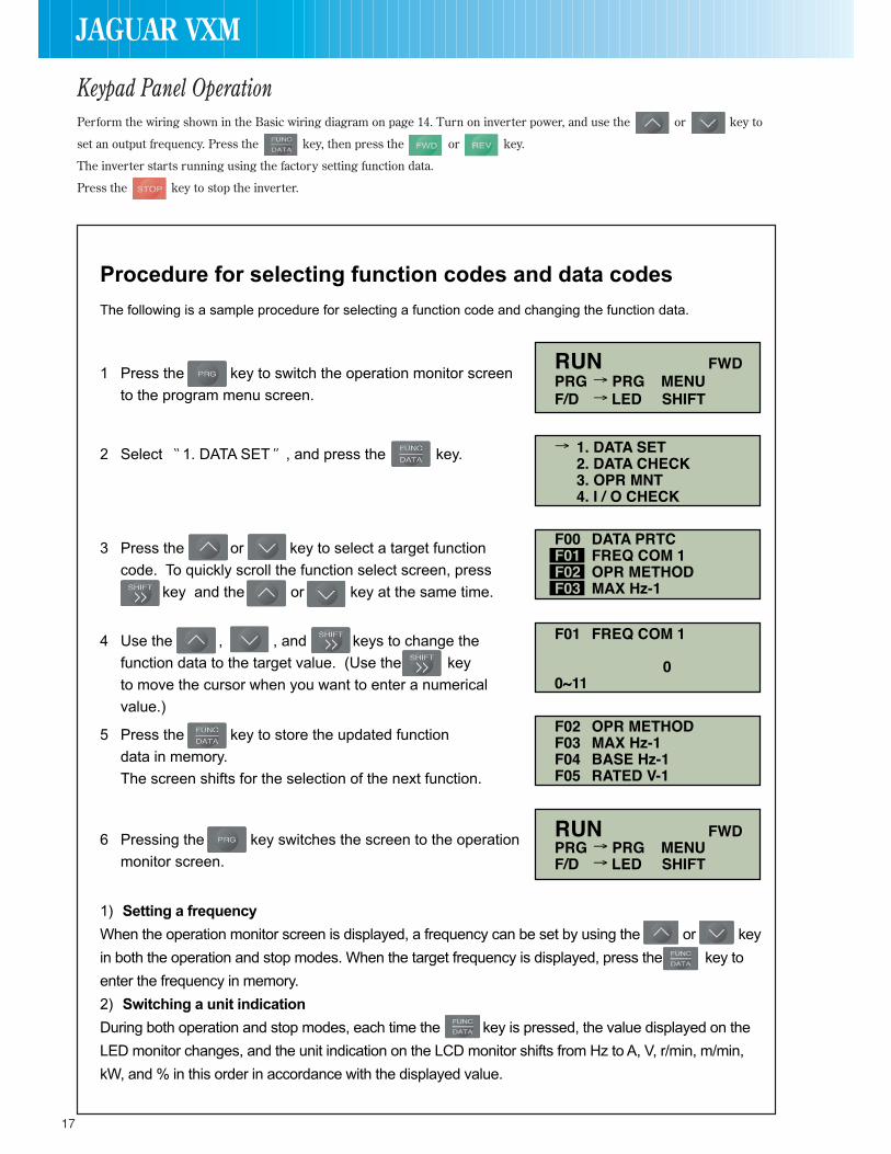
Keypad Panel Operation
17
Perform the wiring shown in the Basic wiring diagram on page 14. Turn on inverter power, and use the or key to
set an output frequency. Press the key, then press the or key.
The inverter starts running using the factory setting function data.
Press the key to stop the inverter.
JAGUAR VXM

18
JAGUAR VXMFUNCTION SETTINGS
FunctionSetting range
Min. Factory settingCode Name LCD monitor unit -22kW 30kW-
Basic Data protection DATA PRTC 0 : Data change enable – 0Functions 1 : Data protectionFrequency command 1 FREQ CMD 1 0 : KEYPAD operation ( or key)
1 : Voltage input (terminals 12 and V2) (0 to +10VDC, 0 to +5VDC)2 : Current input (terminal C1) (4 to 20mA DC)3 : Voltage and current input (terminals 12 and C1)4 : Reversible operation with polarity (terminal 12) (0 to ±10VDC)5 : Reversible operation with polarity (terminals 12 and V1) (0 to ±10VDC)6 : Inverse mode operation (terminals 12 and V2) (+10 to 0VDC)7 : Inverse mode operation (terminal C1) (20 to 4mA DC)8 : UP/DOWN control 1 (initial freq. = 0Hz)9 : UP/DOWN control 2 (initial freq. = last value)10 : PATTERN operation11 : DI option or Pulse train input
Operation method OPR METHOD 0 : KEYPAD operation ( or or key) – 01 : FWD or REV command signal operationMaximum frequency 1 MAX Hz-1 50 to 400Hz 1Hz 50Base frequency 1 BASE Hz-1 25 to 400Hz 1Hz 50Rated voltage 1 RATED V-1 0 (Free), 320 to 480V 1V 400(at Base frequency 1)Maximum voltage 1 MAX V-1 320 to 480V 1V 400(at Maximum frequency 1)Acceleration time 1 ACC TIME 1 0.01 to 3600s 0.01s 6.00 20.00Deceleration time 1 DEC TIME 1 0.01 to 3600s 0.01s 6.00 20.00Torque boost 1 TRQ BOOST 1 0.0 : Automatic (for constant torque load) 0.00.1 to 1.9 : Manual (for variable torque load) 0.1
2.0 to 20.0 : Manual (for constant torque load) (EV : 0.1)
Electronic thermal (Select) ELCTRN OL1 0 : Inactiveoverload relay 1 : Active (for 4-pole standard motor) – 1for motor 1 2 : Active (for 4-pole inverter motor)
(Level) OL LEVEL 1 Approx. 20 to 135% of rated current 0.01A *1)(Thermal time constant) TIME CNST 1 0.5 to 75.0 min 0.1 min. 5.0 10.0
Electronic thermal DBR OL (7.5kW or smaller)overload relay 0 : Inactive(for braking resistor) 1 : Active (for built-in braking resistor) – 1
2 : Active (for external braking resistor)(11kW or larger)0 : Inactive – 0
Restart mode after RESTART 0 : Inactive (Trip and alarm when power failure occurs.)momentary power failure 1 : Inactive (Trip and alarm when power recovers.)
2 : Inactive (Deceleration stop and alarm.)3 : Active (Smooth recovery by continuous operation mode) – 04 : Active (Momentarily stops and restarts at output frequency of before power failure)5 : Active (Momentarily stops and restarts at starting frequency)
Frequency limit (High) H LIMITER 0 to 400Hz 1Hz 70(Low) L LIMITER 0 to 400Hz 1Hz 0
Gain (for frequency FREQ GAIN 0.0 to 200.0% 0.1% 100.0setting signal)Bias frequency FREQ BIAS -400.0 to 400.0Hz 0.1Hz 0.0DC brake (Starting freq.) DC BRK Hz 0.0 to 60.0Hz 0.1Hz 0.0
(Braking level) DC BRK LVL 0 to 100% 1% 0(Braking time) DC BRK t 0.0 (DC brake inactive). 01. to 30.0s 0.1s 0.0
Starting Frequency (Freq.) START Hz 0.1 to 60.0Hz 0.1Hz 0.5(Holding time) HOLDING t 0.0 to 10.0s 0.1s 0.0
Stop frequency STOP Hz 0.1 to 6.0Hz 0.1Hz 0.2Motor sound (Carrier freq.) MTR SOUND CT use VT use*
0.75 to 15kHz (Up to 55kW) 0.75 to 15kHz (Up to 22kW)0.75 to 10kHz (75kW and above) 0.75 to 10kHz (30 to 75kW) 1kHz 15 (Up to 55kW)*
0.75 to 6kHz (90kW and above) 10 (75kW and above)**In case of VT use, carrier frequency should be adjusted depending on capacity.
(Sound tone) SOUND TONE 0 : level 01 : level 12 : level 2 – 03 : level 3
FMA (Voltage adjust) FMA V-ADJ 0 to 200% 1% 100(Function) FMA FUNC 0 : Output frequency 1 (Before slip compensation)
1 : Output frequency 2 (After slip compensation)2 : Output current3 : Output voltage4 : Output torque5 : Load factor – 06 : Input power7 : PID feedback value8 : PG feedback value9 : DC link circuit voltage10 : Universal AO
FMP (Pulse rate) FMP PULSES 300 to 6000 p/s (at full scale) 1 p/s 1440(Voltage adjust) FMP V-ADJ 0% : Pulse rate output: 50% duty)
1 to 200% : Voltage adjust: 2670 p/s, duty adjust) 1% 0
(Function) FMA FUNC 0 : Output frequency 1 (Before slip compensation)1 : Output frequency 2 (After slip compensation)2 : Output current3 : Output voltage4 : Output torque5 : Load factor – 06 : Input power7 : PID feedback value8 : PG feedback value9 : DC link circuit voltage10 : Universal AO
30RY operation mode 30RY MODE 0 : The relay (30) excites on trip mode. – 01 : The relay (30) excites on normal mode.Torque limiter 1 (Driving) DRV TRQ 1 20 to 200, 999% (999: No limit) *2) 1% 180 150
(Braking) BRK TRQ 1 0 (Automatic deceleration control), 20 to 200, 999% (999: No limit) *2) 1% 150 100Torque vector control 1 TRQVECTOR 1 0 : Inactive – 01 : Active
The functions in the white boxes can be set while the inverter is running. Other functions must be set while the inverter is stopped.
F00
F01
F02
F03
F04
F05
F06
F07
F08
F09
F10
F11
F12F13
F14
F15
F16
F17
F18
F20
F21
F22
F23
F24
F25
F26
F27
F30
F31
F33
F34
F35
F36
F40
F41F42
Fundamental Functions
19
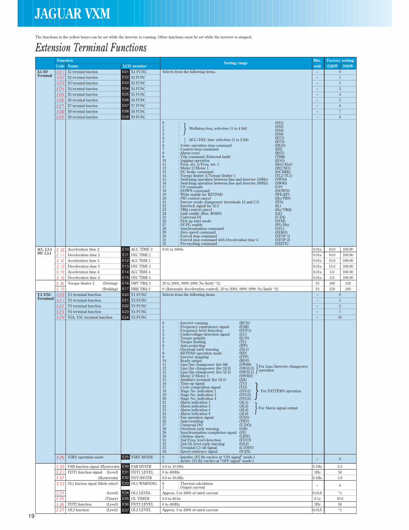
FunctionSetting range
Min. Factory settingCode Name LCD monitor unit -22kW 30kW-
X1-X9 X1 terminal function X1 FUNC Selects from the following items. – 0Terminal X2 terminal function X2 FUNC – 1
X3 terminal function X3 FUNC – 2X4 terminal function X4 FUNC – 3X5 terminal function X5 FUNC – 4X6 terminal function X6 FUNC – 5X7 terminal function X7 FUNC – 6X8 terminal function X8 FUNC – 7X9 terminal function X9 FUNC – 8
0 : (SS1)1 : (SS2)2 : Multistep freq. selection (1 to 4 bit) (SS4)3 : (SS8)4 : (RT1)5 : ACC/DEC time selection (1 to 2 bit) (RT2)6 : 3-wire operation stop command (HLD)7 : Coast-to-stop command (BX)8 : Alarm reset (RST)9 : Trip command (External fault) (THR)10 : Jogging operation (JOG)11 : Freq. set. 2/Freq. set. 1 (Hz2/Hz1)12 : Motor 2/Motor 1 (M2/M1)13 : DC brake command (DCBRK)14 : Torque limiter 2/Torque limiter 1 (TL2/TL1)15 : Switching operation between line and inverter (50Hz) (SW50)16 : Switching operation between line and inverter (60Hz) (SW60)17 : UP command (UP)18 : DOWN command (DOWN)19 : Write enable for KEYPAD (WE-KP)20 : PID control cancel (Hz/PID)21 : Inverse mode changeover (terminals 12 and C1) (IVS)22 : Interlock signal for 52-2 (IL)23 : TRQ control cancel (Hz/TRQ)24 : Link enable (Bus, RS485) (LE)25 : Universal DI (U-DI)26 : Pick up start mode (STM)27 : SY-PG enable (PG/Hz)28 : Synchronisation command (SYC)29 : Zero speed command (ZERO)30 : Forced stop command (STOP 1)31 : Forced stop command with Deceleration time 4 (STOP 2)32 : Pre-exciting command (EXITE)
ACC, 2,3,4 Acceleration time 2 ACC TIME 2 0.01 to 3600s 0.01s 10.0 100.00DEC 2,3,4 Deceleration time 2 DEC TIME 2 0.01s 10.0 100.00
Acceleration time 3 ACC TIME 3 0.01s 15.0 100.00Deceleration time 3 DEC TIME 3 0.01s 15.0 100.00Acceleration time 4 ACC TIME 4 0.01s 3.0 100.00Deceleration time 4 DEC TIME 4 0.01s 3.0 100.00Torque limiter 2 (Driving) DRV TRQ 2 20 to 200%, 999% (999: No limit) *2) 1% 180 150
(Braking) BRK TRQ 2 0 (Automatic deceleration control), 20 to 200%, 999% (999: No limit) *2) 1% 150 100Y1-Y5C Y1 terminal function Y1 FUNC Selects from the following items – 0Terminal Y2 terminal function Y2 FUNC – 1
Y3 terminal function Y3 FUNC – 2Y4 terminal function Y4 FUNC – 7Y5A, Y5C terminal function Y5 FUNC – 10
0 : Inverter running (RUN)1 : Frequency equivalence signal (FAR)2 : Frequency level detection (FDT1)3 : Undervoltage detection signal (LU)4 : Torque polarity (B/D)5 : Torque limiting (TL)6 : Auto-restarting (IPF)7 : Overload early warning (OL1)8 : KEYPAD operation mode (KP)9 : Inverter stopping (STP)10 : Ready output (RDY)11 : Line/Inv changeover (for 88) (SW88)12 : Line/Inv changeover (for 52-2) (SW52-2) For Line/Inverter changeover13 : Line/Inv changeover (for 52-1) (SW52-1) operation14 : Motor 2/Motor 1 (SWM2)15 : Auxiliary terminal (for 52-1) (AX)16 : Time-up signal (TU)17 : Cycle competition signal (TO)18 : Stage No. indication 1 (STG1) For PATTERN operation19 : Stage No. indication 2 (STG2)20 : Stage No. indication 4 (STG4)21 : Alarm indication 1 (AL1)22 : Alarm indication 2 (AL2)23 : Alarm indication 4 (AL4) For Alarm signal output24 : Alarm indication 8 (AL8)25 : Fan operation signal (FAN)26 : Auto-resetting (TRY)27 : Universal DO (U-DO)28 : Overheat early warning (OH)29 : Synchronisation completion signal (SY)30 : Lifetime alarm (LIFE)31 : 2nd Freq. level detection (FDT2)32 : 2nd OL level early warning (OL2)33 : Terminal C1 off signal (C1OFF)34 : Speed existence signal (N-EX)
Y5RY operation mode Y5RY MODE 0 : Inactive (Y5 Ry excites at “ON signal” mode.)1 : Active (Y5 Ry excites at “OFF signal” mode.) – 0
FAR function signal (Hysteresis) FAR HYSTR 0.0 to 10.0Hz 0.1Hz 2.5FDT1 function signal (Level) FDT1 LEVEL 0 to 400Hz 1Hz 50
(Hysteresis) FDT HYSTR 0.0 to 30.0Hz 0.1Hz 1.0OL1 function signal (Mode select) OL1 WARNING 0 : Thermal calculation
1 : Output current – 0
(Level) OL1 LEVEL Approx. 5 to 200% of rated current 0.01A *1(Timer) OL TIMER 0.0 to 60.0s 0.1s 10.0
FDT2 function (Level) FDT2 LEVEL 0 to 400Hz 1Hz 50OL2 function (Level) OL2 LEVEL Approx. 5 to 200% of rated current 0.01A *1
The functions in the yellow boxes can be set while the inverter is running. Other functions must be set while the inverter is stopped.
E01E02
E03
E04
E05
E06
E07
E08
E09
E10
E11
E12
E13
E14
E15
E16
E17
E20
E21
E22
E23
E24
E25
E30
E31
E32
E33
E34
E35
E36
E37
JAGUAR VXM
Extension Terminal Functions

20
JAGUAR VXMFUNCTION SETTINGS
FunctionSetting range
Min. Factory settingCode Name LCD monitor unit -22kW 30kW-
LED & LCD Display coefficient A COEF A -999.00 to 999.00 0.01 0.01Monitor Display coefficient B COEF B -999.00 to 999.00 0.01 0.00
LED Display filter DISPLAY FL 0.0 to 5.0s 0.1s 0.5LED Monitor (Function) LED MNTR 0 : Output frequency 1 (Before slip compensation) (Hz)
1 : Output frequency 2 (After slip compensation) (Hz)2 : Setting frequency (Hz)3 : Output current (A)4 : Output voltage (V)5 : Motor synchronous speed)r/min)6 : Line speed (m/min) – 07 : Load shaft speed (r/min)8 : Torque calculation value (%)9 : Input power10 : PID reference value11 : PID reference value (remote)12 : PID feedback value
(Display at STOP mode) LED MNTR2 0 : Setting value1 : Output value – 0
LCD Monitor (Function) LCD MNTR 0 : Displays operation guidance1 : Bar graph (Output freq. Output current and Output torque) – 0
Language LANGUAGE 0 : Japanese1 : English2 : German3 : French – 14 : Spanish5 : Italian
LCD Monitor (Contrast) CONTRAST 0 (Soft) to 10 (Hard) – 5
The functions in the white boxes can be set while the inverter is running. Other functions must be set while the inverter is stopped.
The functions in the white boxes can be set while the inverter is running. Other functions must be set while the inverter is stopped.
E40
E41
E42
E43
E44
E45
E46
E47
FunctionSetting range
Min. Factory settingCode Name LCD monitor unit -22kW 30kW-
Jump Hz Jump (Jump freq. 1) JUMP Hz 1 0 to 400Hz 1Hz 0Control frequency (Jump freq. 2) JUMP Hz 2 1Hz 0
(Jump freq. 3) JUMP Hz 3 1Hz 0(Hysteresis) JUMP HYSTR 0 to 30Hz 1Hz 3
Multi-Hz Multistep (Freq. 1) MULTI Hz-1 0.00 to 400.00Hz 0.01Hz 0.00Control frequency (Freq. 2) MULTI Hz-2 0.01Hz 0.00setting
(Freq. 3) MULTI Hz-3 0.01Hz 0.00(Freq. 4) MULTI Hz-4 0.01Hz 0.00(Freq. 5) MULTI Hz-5 0.01Hz 0.00(Freq. 6) MULTI Hz-6 0.01Hz 0.00(Freq. 7) MULTI Hz-7 0.01Hz 0.00(Freq. 8) MULTI Hz-8 0.01Hz 0.00(Freq. 9) MULTI Hz-9 0.01Hz 0.00
(Freq. 10) MULTI Hz10 0.01Hz 0.00(Freq. 11) MULTI Hz11 0.01Hz 0.00(Freq. 12) MULTI Hz12 0.01Hz 0.00(Freq. 13) MULTI Hz13 0.01Hz 0.00(Freq. 14) MULTI Hz14 0.01Hz 0.00(Freq. 15) MULTI Hz15 0.01Hz 0.00
JOG frequency JOG Hz 0.00 to 400.00Hz 0.01Hz 5.00PATTERN PATTERN (Mode select) PATTERN 0 : Active (Mono-cycle operation, and then stops.)Operation operation 1 : Active (Continuous cyclic operation while operation command is effective.) – 0
2 : Active (Mono-cycle operation then continues at final frequency.)(Stage 1) STAGE 1 • Operation time: 0.00 to 6000s 0.01s 0.00 F1(Stage 2) STAGE 2 • F1 to F4 and R1 to R4 0.01s 0.00 F1(Stage 3) STAGE 3 Code FWD/REV ACC/DEC 0.01s 0.00 F1(Stage 4) STAGE 4 F1: FWD ACC1/DEC1 0.01s 0.00 F1(Stage 5) STAGE 5 F2: FWD ACC2/DEC2 0.01s 0.00 F1(Stage 6) STAGE 6 F3: FWD ACC3/DEC3 0.01s 0.00 F1(Stage 7) STAGE 7 F4: FWD ACC4/DEC4 0.01s 0.00 F1
*Setting for R1: REV ACC1/DEC1operation time, R2: REV ACC2/DEC2FWD/REV rotation and R3: REV ACC3/DEC3ACC/DEC time select. R4: REV ACC4/DEC4Frequency command 2 FREQ CMD 2 0 : KEYPAD operation ( or key)
1 : Voltage input (terminal 12) (0 to +10VDC, 0 to +5VDC)2 : Inactive3 : Inactive4 : Reversible operation with polarity (terminal 12) (0 to ±10VDC)5 : Reversible operation with polarity (terminal 12 and V1) (0 to ±10VDC)6 : Inverse mode operation (terminal 12) (+10 to 0VDC) – 27 : Inactive8 : UP/DOWN control 1 (initial freq. = 0Hz)9 : UP/DOWN control 2 (initial freq. = last value)10 : PATTERN operation11 : DI option or Pulse train input
Bias (Terminal 12) BIAS 12 -100 to +100.0% 0.1% 0.0Gain (Terminal 12) GAIN 12 0.0 to +200.0% 0.1% 100.0Analog setting signal filter REF FILTER 0.00 to 5.00s 0.01s 0.05
C01
C02C03
C04
C05
C06
C07
C08
C09
C10
C11
C12
C13
C14
C15
C16
C17
C18
C19C20
C21
C22
C23
C24
C25
C26
C27
C28
C30
C31
C32
C33
Extension Terminal Functions (cont’d)
Control Functions of Frequency

21
FunctionSetting range
Min. Factory settingCode Name LCD monitor unit -22kW 30kW-
Motor 1 Number of motor 1 poles M1 POLES 2 to 14 2 4Motor 1 (Capacity) M1-CAP 22kW or smaller : 0.01 to 45.00kW
30kW or larger : 0.01 to 500.00kW 0.01kW *1)
(Rated current) M1-lr 0.00 to 2000A 0.01A *1)(Tuning) M1 TUN1 0 : Inactive
1 : Active (Tuning of %R1 and %X (static test)) – 02 : Active (Tuning of %R1, %X and lo (dynamic test))
(On-line Tuning) M1 TUN2 0 : Inactive1 : Active (Real time tuning of %R2) – 0
(No-load current) M1-lo 0.00 to 2000A 0.01A *1)(%R1 setting) M1-%R1 0.00 to 50.00% 0.01% *1)
(%X setting) M1-%X 0.00 to 50.00% 0.01% *1)(Slip compensation control 1) SLIP COMP1 0.00 to +15.00 0.01Hz 0.00
P01
P02
P03
P04
P05
P06
P07
P08
P09
FunctionSetting range
Min. Factory settingCode Name LCD monitor unit -22kW 30kW-
High Data initialising DATA INIT 0 : Manual set valuePerformance (Data reset) 1 : Return to factory set value – 0Functions Auto-reset (Times) AUTO-RESET 0 (Inactive), 1 to 10 times 1 0
(Reset interval) RESET INT 2 to 20s 1s 5Fan stop operation FAN STOP 0 : Inactive
1 : Active (Fan stops at low temperature mode) – 0
ACC/DEC (Mode select) ACC PTN 0 : Linearpattern 1 : S-curve (weak)
2 : S-curve (strong) – 03 : Non-linear (For variable torque load)
Rev. phase sequence lock REV LOCK 0 : Inactive1 : Active – 0
Start mode START MODE 0 : Inactive(Rotating motor pick-up) 1 : Active (Only when Auto-restart after momentary power failure mode) – 0
2 : Active (All start modes)Energy-saving operation ENERGY SAV 0 : Inactive 0
1 : Active (Only when torque boost “F09” is set at manual setting mode.) – (EV : 1)DEC mode DEC MODE 0 : Normal (according to “H07” mode)
1 : Coast-to-stop – 0
Instantaneous overcurrent INST CL 0 : Inactivelimiting 1 : Active – 1
Auto-restart (Restart time) RESTART t 0.1 to 10.0s 0.1s 0.1 0.5(Freq. fall rate) FALL RATE 0.00 to 100.00Hz/s 0.01Hz/s 10.00
(Holding DC voltage) HOLD V 400 to 600V 1V 470(OPR command selfhold time) SELFHOLD t 0.0 to 30.0s, 999s (999s : The operation command is held while DC link circuit voltage is
larger than 50V.) 0.1s 999
Torque control TRQ CTRL 0 : Inactive (Frequency control)1 : Active (Torque control by terminal 12 (Driving))
(0 to +10V/0 to 200%) – 02 : Active (Torque control by terminal 12 (Driving and Braking)
(0 to ±10V/0 to ±200%)Active drive AUT RED 0 : Inactive
1 : Active – 0
PID PID control (Mode select) PID MODE 0 : InactiveControl 1 : Active (PID output 0 to 100%/frequency 0 to max.) – 0
2 : Active (Inverse operation mode: PID output 0 to 100%/frequency max. to 0)(Feedback signal) FB SIGNAL 0 : Terminal 12 (0 to +10V)
1 : Terminal C1 (4 to 20mA)2 : Terminal 12 (+10 to 0V) – 13 : Terminal C1 (20 to 4mA)
(P-gain) P-GAIN 0.01 to 10.00 0.01 0.10(I-gain) I-GAIN 0.0: Inactive
0.1 to 3600.0s 0.1s 0.0
(D-gain) D-GAIN 0.00: Inactive0.01 to 10.0s 0.01s 0.00
(Feedback filter) FB FILTER 0.0 to 60.0s 0.1s 0.5Y1-Y5C PTC thermistor (Mode select) PTC MODE 0 : InactiveTerminal 1 : Active – 0
(Level) PTC LEVEL 0.00 to 5.00V 0.01V 1.60Droop operation DROOP -9.9 to 0.0Hz 0.1Hz 0.0
Serial Serial link (Function select) LINK FUNC (Code) (Monitor) (Frequency command) (Operation command)Link 0 : X – – x : Valid
1 : X X – – : Invalid – 02 : X – X3 : X X X
RS 485 (Address) 485 ADDRESS 1 to 31 1 1(Mode select on no MODE ON ER 0 : Trip and alarm (Er8)
response error) 1 : Operation for H33 timer and alarm (Er8)2 : Operation for H33 timer and retry to communicate. – 0
*If the retry fails, then the inverter trips (“Er8”)3 : Continuous operation
(Timer) TIMER 0 to 60.0s 0.1s 2.0(Baud rate) BAUD RATE 0 : 19200 bit/s
1 : 96002 : 4800 – 13 : 24004 : 1200
(Data length) LENGTH 0 : 8 bit1 : 7 bit – 0
(Parity check) PARITY 0 : No checking1 : Even parity – 02 : Odd parity
(Stop bits) STOP BITS 0 : 2 bit1 : 1 bit – 0
(No response error) NO RES t 0 (No detection), 1 to 60sdetection time) 1s 0
(Response interval) INTERVAL 0.00 to 1.00s 0.01s 0.01
H03
H04
H05
H06
H07
H08
H09
H10
H11
H12
H13H14
H15
H16
H18
H19
H20
H21
H22H23
H24
H25H26
H27
H28
H30
H31
H32
H33
H34
H35
H36
H37
H38
H39
EXTENSION TERMINAL FUNCTIONS
Motor Parameters
High Performance Functions
The functions in the white boxes can be set while the inverter is running. Other functions must be set while the inverter is stopped.

JAGUAR VXMFUNCTION SETTINGS
FunctionSetting range
Min. Factory settingCode Name LCD monitor unit -22kW 30kW-
Motor 2 Maximum frequency 2 MAX Hz-2 50 to 400Hz 1Hz 50Base frequency 2 BASE Hz-2 25 to 400Hz 1Hz 50Rated voltage RATED V-2 0 (Free), 320 to 480V(at Base frequency 2) 1V 400
Maximum voltage 2 MAX V-2 320 to 480V(at Maximum frequency 2) 1V 400
Torque boost 2 TRQ BOOST2 0.0 : Automatic (for constant torque load)0.1 to 1.9 : Manual (for variable torque load) – 0.0
2.0 to 20.0 : Manual (for constant torque load) (EV : 01)
Electronic (Select) ELCTRN OL2 0 : Inactivethermal 1 : Active (for 4-pole standard motor) – 1overload relay 2 : Active (for 4-pole inverter motor)for motor 2 (Level) OL LEVEL2 Approx. 20 to 135% of rated current 0.01A *1)
(Thermal time constant) TIME CNST2 0.5 to 75.0 min 0.1 min 5.0 10.0Torque vector control 2 TRQVECTOR2 0 : Inactive
1 : Active – 0
Number of motor 2 poles M2 POLES 2 to 14 2 4Motor 2 (Capacity) M2-CAP 22kW or smaller : 0.01 to 45.00kW
30kW or larger : 0.01 to 500.00kW 0.01kW *1)
(Rated current) M2-lr 0.00 to 2000A 0.01A *1)(Tuning) M2 TUN1 0 : Inactive
1 : Active (Tuning of %R1 and %X (static test)) – 02 : Active (Tuning of %R1, %X and lo (dynamic test))
(On-line Tuning) M2-TUN2 0 : Inactive1 : Active (Real time tuning of %R1 and %X) – 0
(No-load current) M2-lo 0.00 to 2000A 0.01A *1)(%R1 setting) M2-%R1 0.00 to 50.00% 0.01% *1)(%X setting) M2-%X 0.00 to 50.00% 0.01% *1)
Slip compensation control 2 SLIP COMP2 0.00 to +15.00Hz 0.01Hz 0.00
The functions in the white boxes can be set while the inverter is running. Other functions must be set while the inverter is stopped.
A01
A02
A03
A04
A05
A06
A07
A08
A09
A10
A11
A12
A13
A14
A15
A16
A17
A18
Notes:*1) Typical value of standard IMO 4P motor.*2) Percent shall be set according to FUNCTION CODE: P02 or A09, motor capacity.
Torque referenced here may not be obtainable when DATA CODE: 0 is selected for FUNCTION CODE: P02 or A09.
Alternative Motor Parameters
22

Function Description LED monitor
Overcurrent • Stops running to protect inverter from an overcurrent resulting from overload. Duringprotection • Stops running to protect inverter from an overcurrent due to a short-circuit in the acceleration(Short-circuit) output circuit. During(Earth fault) deceleration
• Stops running to protect inverter from an overcurrent due to an earth fault in the While running atoutput circuit. constant speed
• Stops running to protect inverter from an overcurrent resulting from earth fault in • 30kW or larger modelthe output circuit by detecting zero-phase current. only Earth
Overvoltage • The inverter stops when it detects an overvoltage in the DC link circuit. • 400V series: 800VDC or Duringprotection more acceleration
• Protection is not assured Duringif excess AC line voltage is decelerationapplied inadvertently. While running at
constant speed
Incoming surge • Protects the inverter against surge voltage between the main circuit power line and • The inverter may be tripped by some otherprotection earth. protective function.
• Protects the inverter against surge voltage in the main circuit power line.
Undervoltage • Stops the inverter when the DC link circuit voltage drops below undervoltage level. • 400V series : 400VDC or lessprotection • 200V series : 200VDC or less
Input phase loss • The inverter is protected from being damaged when open-phase fault occurs.protection
Overheat • Stops the inverter when it detects excess heat sink temperature in case ofprotection cooling fan failure or overload.
• Stops the inverter when it detects an abnormal rise in temperature in the inverterunit caused by insufficient ventilation in cubicles or an abnormal ambient temperature.
• Stops the inverter when it detects an abnormal rise in temperature inside the inverter.
• When the built-in braking resistor overheats, the inverter stops discharging and 7.5kW or smaller model onlyrunning.
• Function data appropriate for the resistor type (built-in/external) must be set.
Electronic thermal • This function stops the inverter by detecting an inverter overload.overload relay • This function stops the inverter by detecting an overload in a standard motor or Motor 1 overload(Motor protection) inverter motor. Motor 2 overload
Fuse blown • When a blown fuse is detected, the inverter stops running. • 30kW or larger model only
Stall prevention • When an output current exceeds the limit during acceleration, this function lowers • The stall prevention function can be disabled.(Momentary output frequency to prevent an OC1 trip.overcurrent limitation)
Active drive • During running in which acceleration is 60s or longer, this function increases the • The acceleration time can be prolonged up toacceleration time to prevent the occurrence of an OLU trip. three times the preset time.
External alarm input • The inverter stops on receiving external alarm signals. • Use THR terminal function (digital input).
Overspeed • Stops the inverter when the output frequency exceeds the rated maximumprotection frequency by 20%.
PG error Alarm output if encoder (PG) signals are disconnected.
Alarm output • The inverter outputs a relay contact change over signal. • Output terminals: 30A, 30B and 30C(for any fault) • Use the RST terminal function for signal input.Alarm reset • An alarm-stop state of the inverter can be cleared with the RESET key or by a • Even if main power input is turned off, alarmcommand digital input signal (RST). history and trip-cause data are retained.
Alarm history memory • Stores up to four previous alarm conditions.
Storage of data on • The inverter will store and display details of the latest alarm history data.cause of trip
Memory error • The inverter checks memory data after power-on and when the data is written.If a memory error is detected, the inverter trips.
KEYPAD panel • If an error is detected in communication between the inverter and KEYPAD when • When operated by external signals, the invertercommunication the Keypad panel is being used, the inverter trips. continues running. The alarm output (for anyerror fault) is not output. Only Er2 is displayed.
CPU error • If the inverter detects a CPU error caused by noise or some other factor, theinverter trips.
Option • If a checksum error or disconnection is detected during communication, thecommunication error inverter issues an alarm.
Option error • If a linkage error or other option error is detected, the inverter issues an alarm.
Output phase loss If an unbalance of output circuits is detected during auto-tuning, this function issueserror an alarm (and trips the inverter).
RS485 • If an RS485 communication error is detected, the inverter issues an alarm.communication error
NOTES:1) Retaining alarm signal when auxiliary control power supply is not used:
If the inverter power supply is cut off while an internal alarm signal is being output, the alarm signal cannot be retained.2) To issue the RESET command, press the key on the KEYPAD panel or connect terminals RST and P24 and disconnect them afterwards.3) Fault history data is stored for the past four trips.
PROTECTIVE FUNCTIONS
23

24
JAGUAR VXMEXTERNAL DIMENSIONS
VXM40 VXM75
VXM550 VXM750 VXM1100 VXM2200G
VXM150 VXM400
Type D D4 D5VXM40 130 36.5 80VXM75 145 51.5 95
Fig. 2Fig. 1
Fig. 4Fig. 3
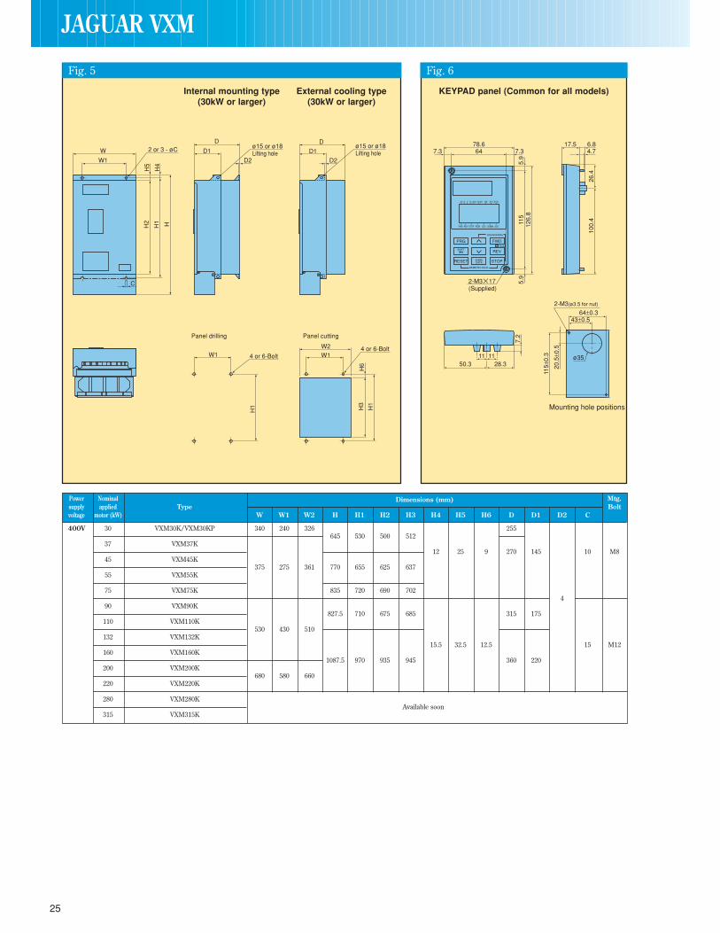
25
KEYPAD panel (Common for all models)Internal mounting type(30kW or larger)
External cooling type(30kW or larger)
Power Nominal Dimensions (mm) Mtg.supply applied Type Boltvoltage motor (kW) W W1 W2 H H1 H2 H3 H4 H5 H6 D D1 D2 C
400V 30 VXM30K/VXM30KP 340 240 326 255645 530 500 512
37 VXM37K12 25 9 270 145 10 M8
45 VXM45K375 275 361 770 655 625 637
55 VXM55K
75 VXM75K 835 720 690 7024
90 VXM90K827.5 710 675 685 315 175
110 VXM110K530 430 510
132 VXM132K15.5 32.5 12.5 15 M12
160 VXM160K1087.5 970 935 945 360 220
200 VXM200K680 580 660
220 VXM220K
280 VXM280KAvailable soon
315 VXM315K
W
W1
C
Panel cutting
2 or 3 - øCD
H2
H5
H1
H4
HD2
W1W2 4 or 6-Bolt
D1ø15 or ø18 Lifting hole
H1
H3
H6
Panel drilling
W1 4 or 6-Bolt
H1
D2
D
D1ø15 or ø18 Lifting hole
JAGUAR VXM
Fig. 5 Fig. 6

26
JAGUAR VXMOPTIONS
Name Function Mounting positionSurge arrester Suppresses induced transient surges from power source, thus protecting all (Contact IMO) equipment connected to the power supply.
Ferrite ring for reducing Reduces radio frequency noise. If the wiring between motor and inverter is radio noise shorter than 20m, use the ferrite ring in the power supply side. If longer than (OC1-OC5) 20m, use it in the output side, if required.
Dynamic brake resistor Converts excess regenerated energy into heat. A light duty resistor is supplied as(DBRRW) standard for drives less than 11kW. For higher powers/duty, extra resistors or
additional equipment is necessary.
RFI Filter This is a special filter which complies with the European EMC (Emission) Directive.(RFMFP/K) This filter should be used with a screened motor cable.
Note: Other prerequisites must be fulfiled to ensure compliance with EMC Directives.Refer to IMO for details.
Optional Sin O/P filter Connected to the output circuit of inverters under low-noise operation with (Contact IMO) carrier frequency from 8 to 15kHz, (6kHz higher for 30kW or larger inverters),
this filter has the following functions:1. Suppresses fluctuation of motor terminal voltage.
Protects the motor insulation from being damaged by PWM voltage overshoot.(400V series)
2. Suppresses leakage current from output side wiring.Reduces leakage current caused when several motors are operated in parallel or connected with long wiring.*Total wiring length should be less than 400m.
3. Suppresses radial noise or inductive coupling from output side wiring.Effective noise suppression device for long wiring applications such as plant.
Note: When connecting this filter, set the carrier frequency F26 at 8kHz or more.
DC Reactor (DCR) (Use the DCR to normalise the power supply in the following cases.](VXMLC) (optional for 1. The power transformer capacity is 500kVA or over and exceeds the inverter smaller power ratings) rated capacity by 10 times.
2. The inverter and a thyristor converter are connected with the same transformer.* Check if the thyristor converter uses a commutation reactor. If not, AC reactor
must be connected to the power supply side.3. Overvoltage trip occurs due to open/close of the phase-advancing capacitor
for the power supply lines.4. The voltage unbalance exceeds 2%.
Voltage unbalance (%) = Max. voltage [V] - Min. Voltage [V] x 67 (%)Three-phase average voltage [V]
(For improving input power-factor, reducing harmonics)• Used to reduce input harmonic current (correcting power-factor)• For the resultant effects, contact IMO.
AC Reactor (ACR) Optional. May be fitted to compensate for long motor cables, or shock loads(LO-3)Frequency meter Analog frequency meter(X72M10V) 72mm square, 0-10VDC, M/C, 1000 /V
Frequency setting device Frequency setting potentiometer (mounted externally)(JAGPOT1K)Output relay and DIN Low power DC coil, 8A capacity, for extending VXM digital outputs Y1-Y4.rail base (VXEJ1)
Reactor, Filter and Other Accessories
* Screened motor cable not shown for simplicity
*
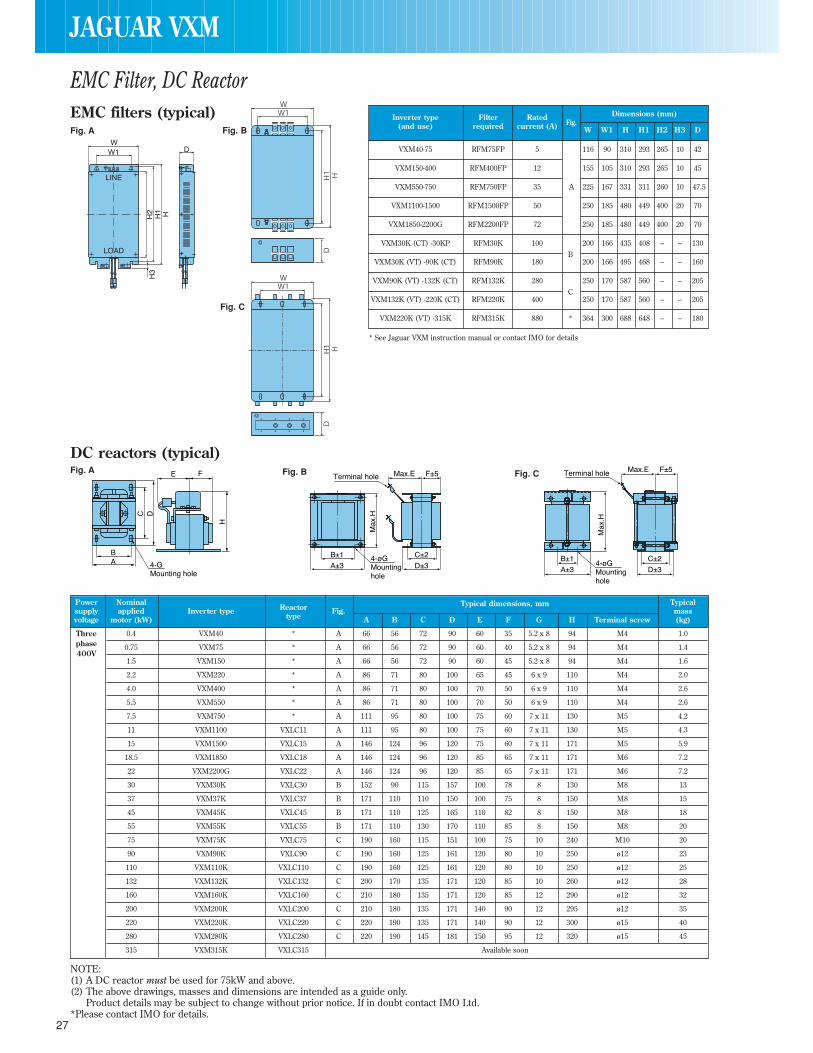
27
EMC filters (typical)
DC reactors (typical)
Dimensions (mm)Inverter type Filter RatedFig.(and use) required current (A) W W1 H H1 H2 H3 D
VXM40-75 RFM75FP 5 116 90 310 293 265 10 42
VXM150-400 RFM400FP 12 155 105 310 293 265 10 45
VXM550-750 RFM750FP 35 A 225 167 331 311 260 10 47.5
VXM1100-1500 RFM1500FP 50 250 185 480 449 400 20 70
VXM1850-2200G RFM2200FP 72 250 185 480 449 400 20 70
VXM30K (CT) -30KP RFM30K 100 200 166 435 408 – – 130
VXM30K (VT) -90K (CT) RFM90K 180B
200 166 495 468 – – 160
VXM90K (VT) -132K (CT) RFM132K 280 250 170 587 560 – – 205
VXM132K (VT) -220K (CT) RFM220K 400C
250 170 587 560 – – 205
VXM220K (VT) -315K RFM315K 880 * 364 300 688 648 – – 180
Power Nominal Typical dimensions, mm Typicalsupply applied Inverter type Reactor Fig. massvoltage motor (kW) type A B C D E F G H Terminal screw (kg)
Three 0.4 VXM40 * A 66 56 72 90 60 35 5.2 x 8 94 M4 1.0phase 0.75 VXM75 * A 66 56 72 90 60 40 5.2 x 8 94 M4 1.4400V
1.5 VXM150 * A 66 56 72 90 60 45 5.2 x 8 94 M4 1.6
2.2 VXM220 * A 86 71 80 100 65 45 6 x 9 110 M4 2.0
4.0 VXM400 * A 86 71 80 100 70 50 6 x 9 110 M4 2.6
5.5 VXM550 * A 86 71 80 100 70 50 6 x 9 110 M4 2.6
7.5 VXM750 * A 111 95 80 100 75 60 7 x 11 130 M5 4.2
11 VXM1100 VXLC11 A 111 95 80 100 75 60 7 x 11 130 M5 4.3
15 VXM1500 VXLC15 A 146 124 96 120 75 60 7 x 11 171 M5 5.9
18.5 VXM1850 VXLC18 A 146 124 96 120 85 65 7 x 11 171 M6 7.2
22 VXM2200G VXLC22 A 146 124 96 120 85 65 7 x 11 171 M6 7.2
30 VXM30K VXLC30 B 152 90 115 157 100 78 8 130 M8 13
37 VXM37K VXLC37 B 171 110 110 150 100 75 8 150 M8 15
45 VXM45K VXLC45 B 171 110 125 165 110 82 8 150 M8 18
55 VXM55K VXLC55 B 171 110 130 170 110 85 8 150 M8 20
75 VXM75K VXLC75 C 190 160 115 151 100 75 10 240 M10 20
90 VXM90K VXLC90 C 190 160 125 161 120 80 10 250 ø12 23
110 VXM110K VXLC110 C 190 160 125 161 120 80 10 250 ø12 25
132 VXM132K VXLC132 C 200 170 135 171 120 85 10 260 ø12 28
160 VXM160K VXLC160 C 210 180 135 171 120 85 12 290 ø12 32
200 VXM200K VXLC200 C 210 180 135 171 140 90 12 295 ø12 35
220 VXM220K VXLC220 C 220 190 135 171 140 90 12 300 ø15 40
280 VXM280K VXLC280 C 220 190 145 181 150 95 12 320 ø15 45
315 VXM315K VXLC315 Available soon
NOTE:(1) A DC reactor must be used for 75kW and above.(2) The above drawings, masses and dimensions are intended as a guide only.
Product details may be subject to change without prior notice. If in doubt contact IMO Ltd.*Please contact IMO for details.
EMC Filter, DC Reactor
JAGUAR VXM
Fig. A Fig. B
Fig. C
Fig. A Fig. B Fig. C
* See Jaguar VXM instruction manual or contact IMO for details

28
JAGUAR VXMOPTIONS
Continuous braking (100% Repetitive braking Continuous braking Repetitive braking
PowerInverter Option CT torque conversion value) (100s or less cycle) VT (MAX. braking torque) (100s or less cycle)
supply Constant Torque Rating (CT) Variable Torque Rating (VT) Braking Braking Max. Braking Discharging Duty Average Max. Braking Discharging Duty Averagevoltage Motor Inverter Motor Inverter Unit resistor braking time capability cycle loss braking time capability cycle loss
(kW) type (kW) type Type Qty (min) kWtorque (s) (kWs) (%) (kW) torque (s) (kWs) (%) (kW)(%) (%)
Three- 0.4 VXM40 – 1 200 0.2 45 9 22 0.044phase 0.75 VXM75 – 1 200 0.2 45 17 18 0.068400V
1.5 VXM150 – – – 1 160 0.4 45 34 10 0.075– – – – –
2.2 VXM220 – 1 160 0.4 30 33 7 0.077
4.0 VXM400 – 1 130 0.4 20 37 5 0.093 15 37 3.5 0.093
5.5 VXM550 7.5 VXM550 – 1 80 0.8 150% 20 55 5 0.138 15 55 3.5 0.138
7.5 VXM750 11 VXM750 – 1 60 0.9 10 38 5 0.188 7 38 3.5 0.188
11 VXM1100 15 VXM1100 1 40 1.4 10 55 5 0.275 100% 7 55 3.5 0.275
15 VXM1500 18.5 VXM1500 VXDBU 1 35 1.4 10 75 5 0.375 8 75 4 0.375
18.5 VXM1850 22 VXM1850 11-22 1 27 1.8 10 93 5 0.463 8 93 4 0.463
22 VXM2200G – – 1 22 1.8 8 88 5 0.55 6 88 3 0.55
– – 30 VXM30KP VXDBU 1 15 3.6 – – – – – 10 150 10 1.5
30 VXM30K 37 VXM30K 30-37 1 15 3.6 10 150 10 1.5 10 150 10 1.5
37 VXM37K 45 VXM37K 1 12 4.8 10 185 10 1.85 10 185 10 1.85
45 VXM45K 55 VXM45KVXDBU
1 10 6 10 225 10 2.25 10 225 10 2.25
55 VXM55K 75 VXM55K45-55
1 7.5 7.2 10 275 10 2.75 10 275 10 2.75
75 VXM75K 90 VXM75K VXDBU 1 6 9.6 100% 10 375 10 3.75 10 375 10 3.75
90 VXM90K 110 VXM90K 75-90 1 5 12 10 450 10 4.5 75% 10 450 10 4.5
110 VXM110K 132 VXM110K VXDBU 1 3.75 14.4 10 550 10 5.5 10 550 10 5.5
132 VXM132K 160 VXM132K 110-132 1 3.33 18 10 660 10 6.6 10 660 10 6.6
160 VXM160K 200 VXM160KVXDBU
1 3.0 19.2 10 800 10 8.0 10 800 10 8.0
200 VXM200K 220 VXM200K 1 2.5 24 10 1000 10 10.0 10 1000 10 10.0
220 VXM220K 280 VXM220K160-220
1 1.88 28.8 10 1100 10 11.0 10 1100 10 11.0
280 VXM280K 315 VXM280K
315 VXM315K 400 VXM315KAvailable soon
NOTE:The braking time and duty cycle (%) are calculated as the constant-torque braking used for deceleration.
(Procedure for selecting options)All three conditions listed below must be satisfied.1. The maximum braking torque does not exceed the value shown in the table.2. The energy discharged in the resistor for each braking (the area of the triangle shown in the above figure) does not exceed the discharging
capability (kWs) in the table.3. The average loss (energy discharged in the resistor divided by a braking interval) does not exceed the average loss (kW) shown in the table.
T1• Duty cycle (%) = T0 x 100[%]Braking power
100%
Braking time T1
Braking time T1
Braking interval T0
Braking Unit, Braking Resistor

29
Name (type) Dimensions
Braking unit
Dimensions (mm) MassVoltage Type Fig. (kg)W W1 H H1 H2 D D1VXDBU 11-22 A See Fig. A – 1.1VXDBU 30-37 B 150 100 – 4
400V VXDBU 45-55230 130
280 265 2501.2 5.5
Series VXDBU 75-90 160VXDBU 110-132
C250 150
370 355 340 9VXDBU 160-220 450 435 420
2.413
Braking resistors(typicalcombinations forheavier dutyapplications)
Ferrite ring
Example 1 – PE380H 160 380W
Covers: VXM150 → VXM400 160 380W
Covers: VXM550 → VXM750 80 760W
Covers: VXM1100 → VXM2200G 40 1520W
Example 2 – PE150H 210 150W
Covers: VXM40 → VXM75 210 150W
Part No. Centre Width Height Depth Mounting Mounting MountingHole C W H D Dim X Dim Y Holes Dia
Ferrite21 (OC1) 21 85 46 22 70 – 5
Ferrite28.5 (OC2) 28.5 105 62 25 90 – 5
Ferrite50 (OC3) 50 150 110 50 125 30 5
Ferrite58 (OC4) 58 200 170 65 180 45 6
Dimensions
C H
Y D
X
W
Optional ferrite ring wiring position for furtherHF noise reduction (if required)
Fig.A165
1.5 10
30
N.P
55
55
21.5
91
170
160
4.5
4030
4.5
Fig.BMounting hole
H2
H1
H
D1.2
W6W1
15 7.5
Fig.C
H2
H1
H
W 6W1
DD1
15 7.5
Ferrite ringMotor
M
Filter Inverter
UV
L1L2L3 W
JAGUAR VXM
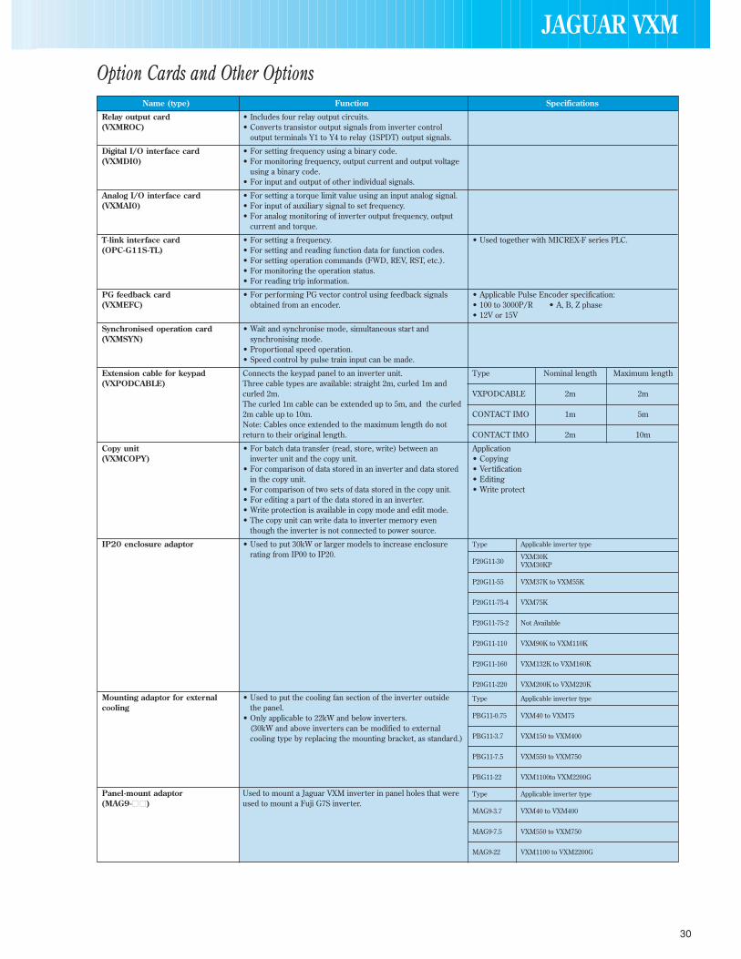
30
JAGUAR VXM
Name (type) Function Specifications
Relay output card • Includes four relay output circuits.(VXMROC) • Converts transistor output signals from inverter control
output terminals Y1 to Y4 to relay (1SPDT) output signals.
Digital I/O interface card • For setting frequency using a binary code.(VXMDI0) • For monitoring frequency, output current and output voltage
using a binary code.• For input and output of other individual signals.
Analog I/O interface card • For setting a torque limit value using an input analog signal.(VXMAI0) • For input of auxiliary signal to set frequency.
• For analog monitoring of inverter output frequency, outputcurrent and torque.
T-link interface card • For setting a frequency. • Used together with MICREX-F series PLC.(OPC-G11S-TL) • For setting and reading function data for function codes.
• For setting operation commands (FWD, REV, RST, etc.).• For monitoring the operation status.• For reading trip information.
PG feedback card • For performing PG vector control using feedback signals • Applicable Pulse Encoder specification:(VXMEFC) obtained from an encoder. • 100 to 3000P/R • A, B, Z phase
• 12V or 15V
Synchronised operation card • Wait and synchronise mode, simultaneous start and(VXMSYN) synchronising mode.
• Proportional speed operation.• Speed control by pulse train input can be made.
Extension cable for keypad Connects the keypad panel to an inverter unit. Type Nominal length Maximum length(VXPODCABLE) Three cable types are available: straight 2m, curled 1m and
curled 2m. VXPODCABLE 2m 2mThe curled 1m cable can be extended up to 5m, and the curled2m cable up to 10m. CONTACT IMO 1m 5mNote: Cables once extended to the maximum length do notreturn to their original length. CONTACT IMO 2m 10m
Copy unit • For batch data transfer (read, store, write) between an Application(VXMCOPY) inverter unit and the copy unit. • Copying
• For comparison of data stored in an inverter and data stored • Vertificationin the copy unit. • Editing
• For comparison of two sets of data stored in the copy unit. • Write protect• For editing a part of the data stored in an inverter.• Write protection is available in copy mode and edit mode.• The copy unit can write data to inverter memory even
though the inverter is not connected to power source.
IP20 enclosure adaptor • Used to put 30kW or larger models to increase enclosurerating from IP00 to IP20.
Mounting adaptor for external • Used to put the cooling fan section of the inverter outsidecooling the panel.
• Only applicable to 22kW and below inverters.(30kW and above inverters can be modified to externalcooling type by replacing the mounting bracket, as standard.)
Panel-mount adaptor Used to mount a Jaguar VXM inverter in panel holes that were(MAG9- ) used to mount a Fuji G7S inverter.
Type Applicable inverter type
VXM30KP20G11-30 VXM30KP
P20G11-55 VXM37K to VXM55K
P20G11-75-4 VXM75K
P20G11-75-2 Not Available
P20G11-110 VXM90K to VXM110K
P20G11-160 VXM132K to VXM160K
P20G11-220 VXM200K to VXM220K
Type Applicable inverter type
PBG11-0.75 VXM40 to VXM75
PBG11-3.7 VXM150 to VXM400
PBG11-7.5 VXM550 to VXM750
PBG11-22 VXM1100to VXM2200G
Type Applicable inverter type
MAG9-3.7 VXM40 to VXM400
MAG9-7.5 VXM550 to VXM750
MAG9-22 VXM1100 to VXM2200G
Option Cards and Other Options
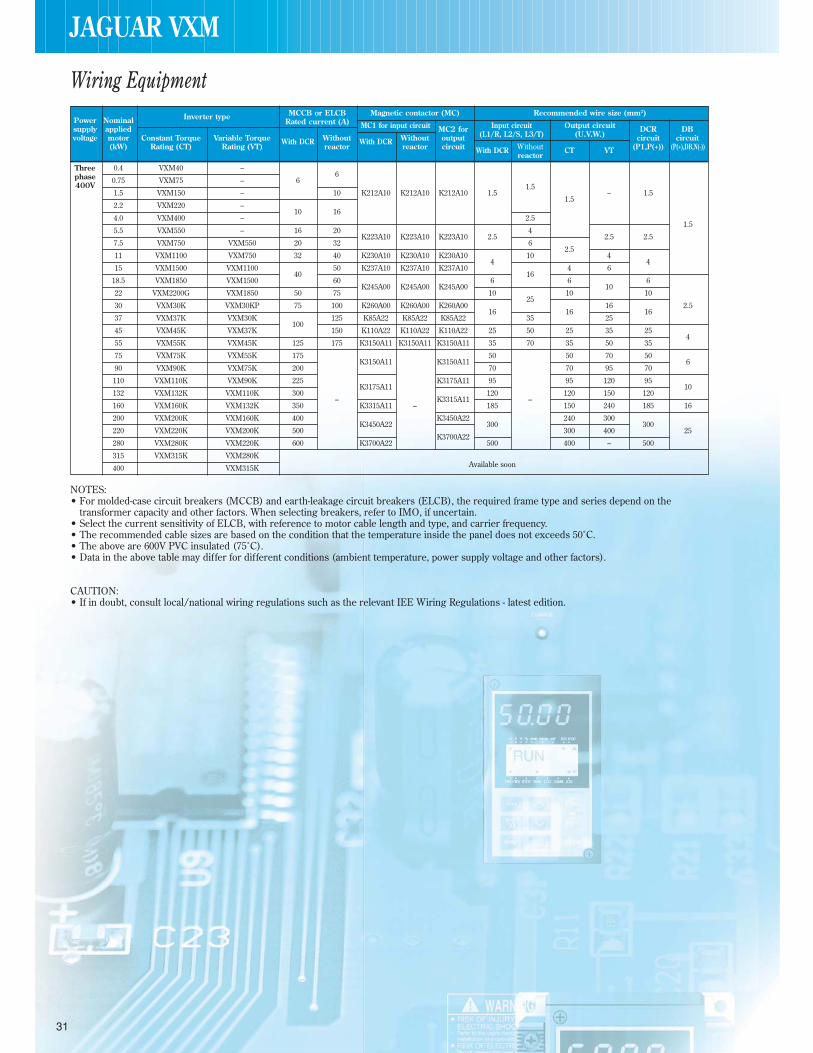
31
Power Nominal Inverter type MCCB or ELCB Magnetic contactor (MC) Recommended wire size (mm2)
supply appliedRated current (A) MC1 for input circuit MC2 for Input circuit Output circuit DCR DB
voltage motor Constant Torque Variable Torque With DCR Without With DCR Without output (L1/R, L2/S, L3/T) (U.V.W.) circuit circuit(kW) Rating (CT) Rating (VT) reactor reactor circuit With DCR Without CT VT (P1,P(+)) (P(+),DB,N(-))
reactor
Three 0.4 VXM40 –6phase 0.75 VXM75 – 6
400V1.5 VXM150 – 10 K212A10 K212A10 K212A10 1.5
1.5– 1.5
2.2 VXM220 –10 16
1.5
4.0 VXM400 – 2.51.5
5.5 VXM550 – 16 20K223A10 K223A10 K223A10 2.5
42.5 2.5
7.5 VXM750 VXM550 20 32 6
11 VXM1100 VXM750 32 40 K230A10 K230A10 K230A10 102.5
4
15 VXM1500 VXM110040
50 K237A10 K237A10 K237A104
4 64
18.5 VXM1850 VXM1500 60K245A00 K245A00
616
610
6
22 VXM2200G VXM1850 50 75K245A00
10 10 10
30 VXM30K VXM30KP 75 100 K260A00 K260A00 K260A0025
16 2.5
37 VXM37K VXM30K100
125 K85A22 K85A22 K85A2216
3516
2516
45 VXM45K VXM37K 150 K110A22 K110A22 K110A22 25 50 25 35 25
55 VXM55K VXM45K 125 175 K3150A11 K3150A11 K3150A11 35 70 35 50 354
75 VXM75K VXM55K 175K3150A11 K3150A11
50 50 70 506
90 VXM90K VXM75K 200 70 70 95 70
110 VXM110K VXM90K 225K3175A11
K3175A11 95 95 120 9510
132 VXM132K VXM110K 300K3315A11
120–
120 150 120
160 VXM160K VXM132K 350–
K3315A11 – 185 150 240 185 16
200 VXM200K VXM160K 400K3450A22
K3450A22300
240 300
220 VXM220K VXM200K 500 300 400300
25
280 VXM280K VXM220K 600 K3700A22K3700A22
500 400 – 500
315 VXM315K VXM280K
400 VXM315K Available soon
NOTES:• For molded-case circuit breakers (MCCB) and earth-leakage circuit breakers (ELCB), the required frame type and series depend on the
transformer capacity and other factors. When selecting breakers, refer to IMO, if uncertain.• Select the current sensitivity of ELCB, with reference to motor cable length and type, and carrier frequency.• The recommended cable sizes are based on the condition that the temperature inside the panel does not exceeds 50˚C.• The above are 600V PVC insulated (75˚C).• Data in the above table may differ for different conditions (ambient temperature, power supply voltage and other factors).
CAUTION:• If in doubt, consult local/national wiring regulations such as the relevant IEE Wiring Regulations - latest edition.
Wiring Equipment
JAGUAR VXM