RFID Reader Networks: Channel allocation algorithms, performance evaluation and simulator

Computer Networks GroupUniversität Paderborn
ChSim – A wireless channel simulator for OMNeT++
Simulation workshop
TKN, TU BerlinSeptember 08, 2006
(c) 2006, Stefan Valentin, [email protected]
2
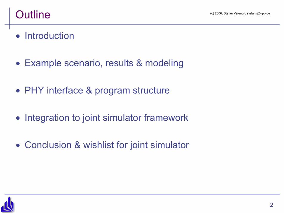
Outline
• Introduction
• Example scenario, results & modeling
• PHY interface & program structure
• Integration to joint simulator framework
• Conclusion & wishlist for joint simulator
(c) 2006, Stefan Valentin, [email protected]
3
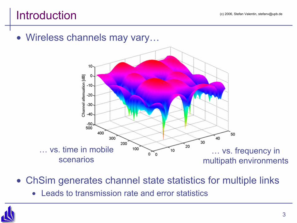
Introduction
• Wireless channels may vary…
• ChSim generates channel state statistics for multiple links• Leads to transmission rate and error statistics
… vs. time in mobile scenarios
… vs. frequency in multipath environments
(c) 2006, Stefan Valentin, [email protected]

4
Scenario example
• A mobile wireless network:
• At runtime: Definition of relative speed and distance by mobility model
• Included: Manhattan grid, (Random waypoint)• Fixed setup is possible
• Mobility parameters are passed to channel models• Included: Clarke’s fading model (Rayleigh), path loss, shadowing,
and correlation
relative distance
relative speed
(c) 2006, Stefan Valentin, [email protected]

5
Modeling fading
• Time selective fading:• Frequency of each fading path ist
shifted according to mobility speed• Doppler shift: fd ~ vrel
• Paths overlap at receiver• Clarke’s model
1. Simplification: There are k discretefading paths
2. Simplification: Isotropic antenna gain pattern• I.e., scatterers are located in a ring
around the mobile receiver⇒ No ray-trace 3D models needed ☺
• Frequency selective fading• Parameterized by delay spread
• Delay variance of paths
(c) 2006, Stefan Valentin, [email protected]
6
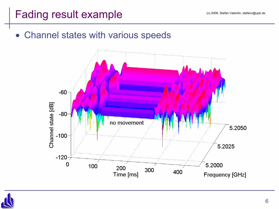
Fading result example
• Channel states with various speeds
(c) 2006, Stefan Valentin, [email protected]

7
Correlation example
• Useful for multiple channel systems, e.g. MIMO, OFDM• Chsim supports link and frequency correlation
0 100 200 300 400 500 600 700 800 900 1000
-30
-20
-10
0
10Channel gain of two uncorrelated links
Samples
H [d
B]
0 100 200 300 400 500 600 700 800 900 1000-40
-30
-20
-10
0
10Channel gain of two correlated links ρ=0.9
H [d
B]
Samples
(c) 2006, Stefan Valentin, [email protected]

8
Interface to physical layer
• Output of Chsim: Attenuation factor h(t)
• One h per time-sample, frequency-band, and link
• With transmission power & noise the PHY:
• Calculates: SNR = h(t) × Es/N0• Selects: Transmission rate using
rate thresholds• Calculates: Error statistics using
coding gain and thresholds• Drawback compared to G.-E.:
• All PHY calculations have to be done per channel sample
• However, with interleaving block fading can be assumed
• Limits sample frequency to one sample per MAC frame
0 0.1 0.2 0.3 0.4 0.5 0.6 0.7 0.8 0.9 1-10
-5
0
5
10
15
20
25
E s/N
0at
rece
iver
[dB
]
SNR per symbol, Ptx
=-9dBm, 50m distance and single 2ms block fading channel with 1m/s motion speed
0 0.1 0.2 0.3 0.4 0.5 0.6 0.7 0.8 0.9 10
1
2
3
4
5
6x 10⁷Ideal rate allocation for the 8 IEEE 802.11a rates, 2ms adaptation cycle, and 2 different bound sets
chos
en tx
-rat
e [B
its/s
]Time [s]
Bounds: L=13500Bytes Bounds: L=1500BytesBounds: L=1500Bytes (min. Gcode
) Bounds: Proxim MP.11a default
PHY not included in ChSim, 802.11a/g PHY implementations
exist
(c) 2006, Stefan Valentin, [email protected]

9
Program structure
• Basic structure: • MobileStation[n]:
• Channel[m]:
• channelStateCalculator:• Channel modeling methods
• errorCalculator:• Empty: no error model in
ChSim
(c) 2006, Stefan Valentin, [email protected]

10
Integration to joint simulator framework
• TriggerGen and Filewriter: • Natural connection to higher layers
• Integrate these (and other channel models) as a:• Single compound module btw. terminals or• OMNeT++ NED connection
• Preferred but requires OMNeT++ changes
• Wish list for joint simulator:• Separation and clean interfaces for/btw.:
• Mobility model (Mobility framework implementations should be used)• Channel • PHY
• Arbitrarily amounts of channels per node and MAC link• E.g. for MIMO
• Different time resolutions for Channel and PHY/MAC modules
(c) 2006, Stefan Valentin, [email protected]

11
Conclusion & future work
• Introduced: ChSim, our contribution to the joint simulator framework
• Provides channel statistics• Analog channel models close to physical scenario
• Advantage vs. G.-E.: Physical parameters can be used directly or considered as factors
• E.g. Analyze performance of MIMO system with channel correlation• Disadvantage vs. G.-E.: Computational overhead ≈ 4 × G.-E.
• Future work:• Revise correlation model, and add further methods• Release 802.11a/g PHY• Documentation
• For joint simulator:• Include more, e.g. digital, channel models• PHY, channel, mobility models should be clearly separated and
connected using clean interfaces
(c) 2006, Stefan Valentin, [email protected]

12
Thank you – Questions?
• Download Chsim at http://wwwcs.upb.de/cs/cn/projects.html
(c) 2006, Stefan Valentin, [email protected]

13
Frequency selective fading
0 5 10 15 20 25 30 35 40 45 50-30
-25
-20
-15
-10
-5
0
5
10
Frequency band
H [d
B]
Delay spread = 10ns = 150ns = 5µs
(c) 2006, Stefan Valentin, [email protected]

14
Rayleigh fading
-70 -60 -50 -40 -30 -20 -10 0 100
1000
2000
3000
4000
5000
6000
7000
8000Histogram of a slow fading channel generated with ChSim
(c) 2006, Stefan Valentin, [email protected]