CHEMICAL VAPOR INFILTRATION PROCESS MODELING AND …
12
CHEMICAL VAPOR INFILTRATION PROCESS MODELING AND OPTIMIZATION T.M. BESMANN*, W.M. MATLIN**, AND D.P. STINTON* *Metals and Ceramics Division, Oak Ridge National Laboratory, Oak Ridge, TN 37831-6063, [email protected] **Department of Materials Science and Engineering)University of Tennessee, Knoxville, TN 37996 ABSTRACT Chemical vapor infiltration is a unique method for preparing continuous fiber ceramic composites that spares the strong but relatively fragile fibers from damaging thermal, mechanical) and chemical degradation. The process is relatively complex and modeling requires detailed phenomenological knowledge of the chemical kinetics and mass and heat transport. An overview of some of the current understanding and modeling of CVI and examples of efforts to optimize the processes is given. Finally, recent efforts to scale-up the process to produce tubular forms are described. INTRODUCTION Chemical vapor infiltration (CVI) is simply chemical vapor deposition ( 0 ) on the internal surfaces of a porous preform. It has been used to produce a variety of developmental materials. The greatest commercial interest is in continuous filament fibrous preforms, in which the high strength fibers can be aligned with the high stress directions. The preforms are infiltrated with carbon or ceramic, taking advantage of the relatively low stress CVD process, and resulting in carbodcarbon or ceramic matrix composites (CMCs). Chemical vapor infiltration originated in efforts to densify porous graphite bodies by infiltration with carbon.' The technique has developed commercially such that half of the carbodcarbon composites currently produced are made by CVI. The remainder are fabricated by curing polymer impregnated fiber layups. The earliest report of CVI for ceramics was a 1964 patent for infiltrating fibrous alumina with chromium carbides.* In CVI, reactants are introduced into a porous preform via either difision or forced convection, and the CVD precursors deposit the appropriate phase(s). As infiltration proceeds, the deposit on the internal surfaces becomes thicker. Thus after some length of time the growing surfaces meet, bonding the preform and filling much of the free volume with deposited matrix. The major advantage of CVI relative to competing densification processes is the low thermal and mechanical stress to which the sensitive fibers are subjected. CVD can occur at temperatures much more modest than the melting point of the deposited material, and therefore usually well below the sintering temperature. In addition, the process imparts little mechanical stress to the preform as compared to more traditional techniques such as hot-pressing. There are a variety of techniques for infiltration classified as to whether they utilize difision or forced flow for transport of gaseous species, and whether thermal gradients are imposed? Yet only two methods have been found to be practical. The most widely used commercial process is isothermal/isobaric CVI (ICVI)$5 which depends only on difision for species transport. These generally operate at reduced pressure (1-10 kPa) for deposition and transport rate control. Fixturing of the fibrous preforms is needed before initial densification to maintain the proper shape. Density ~esubmitted~~.pthasbeenauthondbyacontractor of the U.S. government uuda contract NO. DEACOS- 96OR2Z464. Acco~, the US. Government retains a nonexclusive, royalty-he license to publish or reproduce the published form of this conhiibution. or dow othcn to do so. f0rU.S. Government purposes." - blSTRlBUTtON' OF'THIS DOCUMENT Is UNLfMmb
Transcript of CHEMICAL VAPOR INFILTRATION PROCESS MODELING AND …
CHEMICAL VAPOR INFILTRATION PROCESS MODELING AND OPTIMIZATION
T.M. BESMANN*, W.M. MATLIN**, AND D.P. STINTON* *Metals and Ceramics Division, Oak Ridge National Laboratory, Oak Ridge, TN 37831-6063, [email protected] **Department of Materials Science and Engineering) University of Tennessee, Knoxville, TN 37996
ABSTRACT
Chemical vapor infiltration is a unique method for preparing continuous fiber ceramic composites that spares the strong but relatively fragile fibers from damaging thermal, mechanical) and chemical degradation. The process is relatively complex and modeling requires detailed phenomenological knowledge of the chemical kinetics and mass and heat transport. An overview of some of the current understanding and modeling of CVI and examples of efforts to optimize the processes is given. Finally, recent efforts to scale-up the process to produce tubular forms are described.
INTRODUCTION
Chemical vapor infiltration (CVI) is simply chemical vapor deposition ( 0 ) on the internal surfaces of a porous preform. It has been used to produce a variety of developmental materials. The greatest commercial interest is in continuous filament fibrous preforms, in which the high strength fibers can be aligned with the high stress directions. The preforms are infiltrated with carbon or ceramic, taking advantage of the relatively low stress CVD process, and resulting in carbodcarbon or ceramic matrix composites (CMCs).
Chemical vapor infiltration originated in efforts to densify porous graphite bodies by infiltration with carbon.' The technique has developed commercially such that half of the carbodcarbon composites currently produced are made by CVI. The remainder are fabricated by curing polymer impregnated fiber layups. The earliest report of CVI for ceramics was a 1964 patent for infiltrating fibrous alumina with chromium carbides.*
In CVI, reactants are introduced into a porous preform via either difision or forced convection, and the CVD precursors deposit the appropriate phase(s). As infiltration proceeds, the deposit on the internal surfaces becomes thicker. Thus after some length of time the growing surfaces meet, bonding the preform and filling much of the free volume with deposited matrix.
The major advantage of CVI relative to competing densification processes is the low thermal and mechanical stress to which the sensitive fibers are subjected. CVD can occur at temperatures much more modest than the melting point of the deposited material, and therefore usually well below the sintering temperature. In addition, the process imparts little mechanical stress to the preform as compared to more traditional techniques such as hot-pressing.
There are a variety of techniques for infiltration classified as to whether they utilize difision or forced flow for transport of gaseous species, and whether thermal gradients are imposed? Yet only two methods have been found to be practical. The most widely used commercial process is isothermal/isobaric CVI (ICVI)$5 which depends only on difision for species transport. These generally operate at reduced pressure (1-10 kPa) for deposition and transport rate control. Fixturing of the fibrous preforms is needed before initial densification to maintain the proper shape. Density
~esubmitted~~.pthasbeenauthondbyacontractor of the U.S. government uuda contract NO. DEACOS- 96OR2Z464. A c c o ~ , the US. Government retains a nonexclusive, royalty-he license to publish or reproduce the published form of this conhiibution. or d o w othcn to do so. f0rU.S. Government purposes."
- blSTRlBUTtON' OF'THIS DOCUMENT Is U N L f M m b

gradients are minimized by a low reaction temperature, although in order to get economical densification rates, deposition is often sufficiently rapid to overcoat the outer surface before infiltration is complete. Interruption of the CVI process for periodic machining of parts is thus necessary for all but the thinnest components, so as to open diffusion paths from the surface. Regardless, this diffusion-dependent process is still slow requiring several-week-long infiltration times. It is commercially attractive, however, because large numbers of parts of varying dimensions are easily accommodated in a single reactor.
The forced-flowhhermal gradient technique (FCVI) developed at Oak Ridge National Laboratory ( O M ) overcomes the problems of slow diffusion and restricted permeability, and has demonstrated a capability to produce thick-walled, simple-shaped components in times of the order of hours6 Its disadvantage lies in the fixturing necessary to maintain both the thermal and pressure gradient, and as such has lagged ICVI in its application.
In a relatively recent development, CVI is being used to prepare low density materials for filtration applications. The 3M Company and DuPont Lanxide, Inc., are producing by CVI particulate filters for hot gas cleanup in advanced coal combustion systems to allow direct passage of combustion gases to a turbine. ORNL with the Cummins Engine Company is developing filters for carbon particulate removal from diesel engine exhaust. The filters are prepared via ICVI using preforms with controlled porosity. In the case of the coal systems, these -2 m long tubular filters have an infiltrated Nextelm (3M Co., Minneapolis, MN) or NicaloP (Nippon Carbon, Tokyo, Japan) cloth structure which is ca-ttgdWit.h_a_slurry of fibers and then re-infiltrated to form the
. -k :.<, 4.2, . filtration surface. L
Economic assessments of CVI processes have indicated that processing time (reactor cost) 4
A '.< 7 can be a major cost element, dominating others such as precursor would most productively focus on reducing densification times while maintaining high and uniform y;.] :. density. This paper has therefore been devoted to a discussion of CVI with a focus on these issues. Additionally, interest in tubular forms for use as high temperature heat exchangers in coal utilization and other applications has prompted efforts to scale-up the process for producing tubes.
Thus process optimization C /
CHEMICAL KINETICS
The CMC material systems of greatest interest utilize S ic as the matrix. S i c is typically deposited fiom methyltrichlorosilane (MTS), or similar chlorosilanes carried in hydrogen. While there has been a wealth of reports on the kinetics of Sic deposition from MTS, the results have been widely disparate? Recent work has noted that Sic formation is complex, and not a simple first order process 9-12, with the overall reaction written:
CH3C13Si + H2 - Sic + 3HC1+ H2
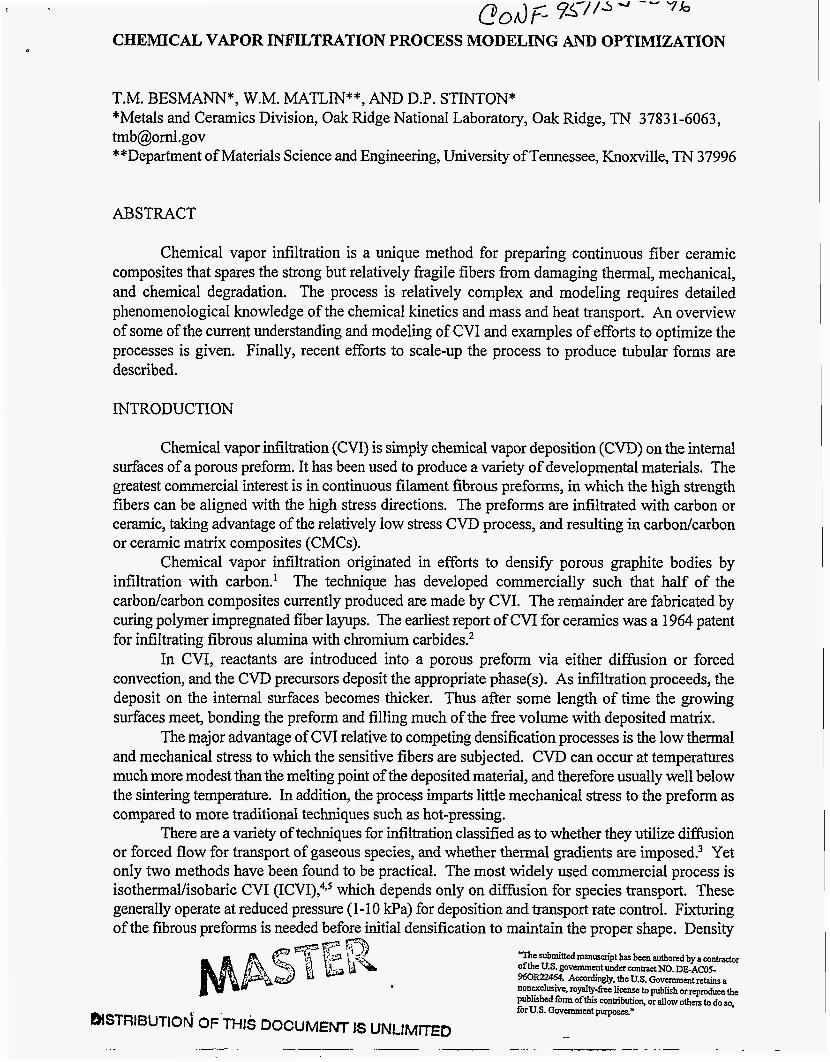
Brennfleck et all3 report a first-order rate expression that has been often used in CVI modeling. Such a simple approach has been shown to be incorrect, but still has resulted in predicted deposition rates not too different from experimentally determined values. Figure 1 illustrates Brennfleck et al's13 rate expression and that derived from the reverse/etch model of Besmann et allo:
1 +kpCp
where u is the deposition rate, k is the rate constant, C is the concentration, and the subscripts R and
P signify reactant and product (HCl), respectively. As is seen in Fig. 1, the production of HCl fiom the depletion of MTS due to the deposition reaction (Eq. 1) has a strong effect on S ic deposition, particularly at lower temperatures. The effect is thus especially important for ICVI, which operates at -1300 K, and for FCVI which utilizes temperatures between 1000 and 1500 K. It has been postulated that the effect fits a relationship for the etching of S ic by HCl. Although site blocking via Langmuir adsorption was evaluated as a likely candidate mechanism, Langmuir-type relationships were not found to be a good fit to the kinetic data." Yet when Sic is exposed to HC1 at temperatures in the range for CVI, extensive etching is not observed. It is thus believed that it is the removal of active surface species that facilitate S ic deposition which is preventing S ic deposition, and this is the controlling, reverse mechanism. S i c grows by alternating addition of Si and C atoms to the growth surface. It is suggested that HCl or some intermediate may likely be removing Si atoms that are adsorbed on the growth surface, thus preventing addition of C atoms and restraining growth." Regardless, without accurately including the effect of HC1 accumulation during infiltration, the deposition rates will be markedly incorrect I
3
2.5
2
1.5 C .- $ 1 C Y
w I- 0.5 a a a 0
-0.5
-1
-1.5
-2
9
I I 1 I I I I I I
- REVERSEETCH --- 1stORDER
/ - 40% H2: MTS = 1011
I I 1 t I I I I I lo00 1 1 0 0 1 2 0 0 1 3 0 0 1 4 0 0
TEMPERATURE (K)
Fig. 1. HCI magnifies the effect of depletion, Le., the effect of the formation of product HCI, on Sic deposition from MTS.
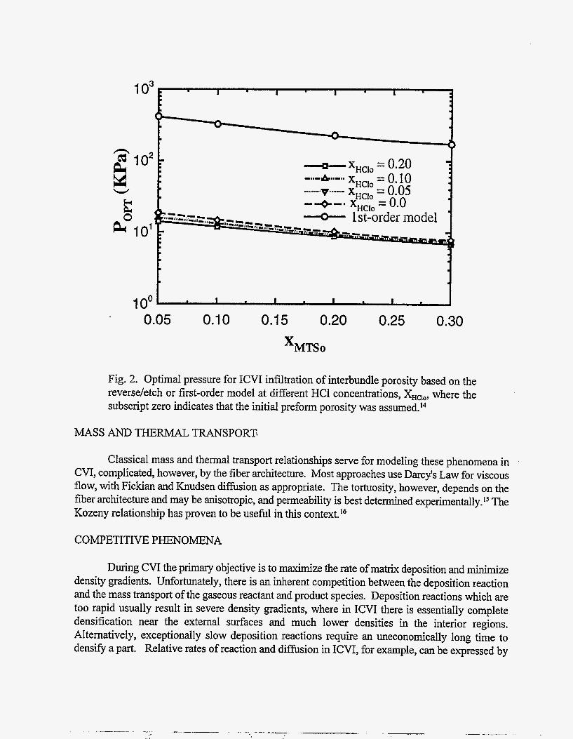
Q The difference between the two relationships for predicting infiltration rates for ICVI has een demonstrated by Sheldon and Chang.I4 Figure 2 is fiom their work and illustrates the
substantial difference in optimal total pressure for densification of the coarser porosity in a preform. The reverse/etch relationship predicts over an order of magnitude lower pressure than does the first- order model. Experience confirms that lower pressures, approaching the 10 kPa range of Fig. 2, yield improved uniformity of densification.
- I
- I
- I_-__
I o3
1- XHClo = 0.20
W ii IO2 E
LO101
1 oo 0.05 0.1 0 0.1 5 0.20 0.25 0.30
Fig. 2. Optimal pressure for ICVI infiltration of interbundle porosity based on the reverse/etch or first-order model at different HCl concentrations, XHclo, where the subscript zero indicates that the initial preform porosity was assumed.14
MASS AND THERMAL TRANSPORT
Classical mass and thermal transport relationships serve for modeling these phenomena in CVI, complicated, however, by the fiber architecture. Most approaches use Darcy's Law for viscous flow, with Fickian and Knudsen diffbsion as appropriate. The tortuosity, however, depends on the fiber architecture and may be anisotropic, and permeability is best determined e~perimentally.'~ The Kozeny relationship has proven to be usefid in this context.16
COMPETITIVE PHENOMENA
During CVI the primary objective is to maximize the rate of matrix deposition and minimize density gradients. Unfortunately, there is an inherent competition between the deposition reaction and the mass transport of the gaseous reactant and product species. Deposition reactions which are too rapid usually result in severe density gradients, where in ICVI there is essentially complete densification near the external surfaces and much lower densities in the interior regions. Alternatively, exceptionally slow deposition reactions require an uneconomically long time to densifl a part. Relative rates of reaction and difision in ICVI, for example, can be expressed by
a dimensionless parameter, the Thiele modulus, @. The Thiele modulus is the ratio of the kinetic deposition rate to the diffusion rate:
where S is the surface area, k is the first-order rate constant, H is half the width of the preform (characteristic length), V is the molar volume of the matrix, and De is the effective diffusion coefficient. Although the deposition rate is not first-order, it can be treated that way at a fixed depletion, allowing use of the Thiele modulus in this form.
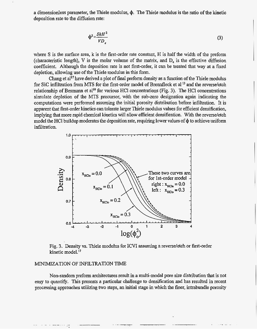
Chang et all7 have derived a plot of final preform density as a function of the Thiele modulus for S i c infiltration from MTS for the first-order model of Brennfleck et al l3 and the reverse/etch relationship of Besmann et all0 for various HCl concentrations (Fig. 3). The HCl concentrations simulate depletion of the MTS precursor, with the sub-zero designation again indicating the computations were performed assuming the initial porosity distribution before infiltration. It is apparent that first-order kinetics can tolerate larger Thiele modulus values for efficient densification, implying that more rapid chemical kinetics will allow efficient densification. With the reverse/etch model the HC1 buildup moderates the deposition rate, requiring lower values of @ to achieve uniform infiltration.
1 .o
0.9
0.8
0.7
0.6
1 " " 1 ' " ' 1 ' " ' I " " I " " I " " I " " ,
-
-4 -3 -2 -1 0 1 2 3 4
Fig. 3. Density vs. Thiele modulus for ICVI assuming a reverse/etch or first-order kinetic rn0de1.I~
MINIMIZATION OF INFILTRATION TIME
Non-random preform architectures result in a multi-modal pore size distribution that is not easy to quantify. This presents a particular challenge to densification and has resulted in recent processing approaches utilizing two steps, an initial stage in which the finer, intrabundle porosity
is efficiently filled, and a second stage which assumes the fine porosity is no longer available and seeks to rapidly fill the coarser, interbundle pores.
4 -
2 -
Pore Size Distribution
-
interbundle (larger pores) - //
, * . ! # 3 * , ! t , * , l , , , ,
The typical cloth layup for CVI generates a bimodal pore size distribution representing the intrabundle (within the fiber bundle or tow) and interbundle (between fiber bundles or tows in the cloth weave or between cloth layers) void space."-" Star?* has estimated that in a 40 vol.% fiber, plain weave NicalonTM cloth layup, the fine and coarse porosity account for approximately equal fractions.
Minimizing ICVI Time
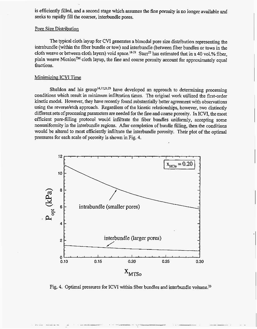
Sheldon and his g r ~ u p ' ~ * ' ' ~ ' ~ ~ have developed an approach to determining processing conditions which result in minimum infiltration times. The original work utilized the first-order kinetic model. However, they have recently found substantially better agreement with observations using the reverse/etch approach. Regardless of the kinetic relationships, however, two distinctly different sets of processing parameters are needed for the fine and coarse porosity. In ICVI, the most efficient pore-filling protocol would infiltrate the fiber bundles uniformly, accepting some nonuniformity in the interbundle regions. After completion of bundle filling, then the conditions would be altered to most efficiently infiltrate the interbundle porosity. Their plot of the optimal pressures for each scale of porosity is shown in Fig. 4.
Y a PP
12
10
8
6
Fig. 4. Optimal pressures for ICVI within fiber bundles and interbundle v0lume.2~
. I
Minimizing FCVI Time
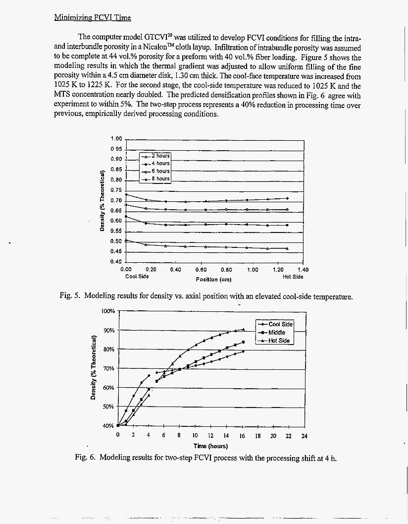
The computer model GTCVI” was utilized to develop FCVI conditions for filling the intra- and interbundle porosity in a Nicalonm cloth layup. Infiltration of intrabundle porosity was assumed to be complete at 44 vol.% porosity for a preform with 40 vol.% fiber loading. Figure 5 shows the modeling results in which the thermal gradient was adjusted to allow uniform filling of the fine porosity within a 4.5 cm diameter disk, 1.30 cm thick. The cool-face temperature was increased from 1025 IS to 1225 K. For the second stage, the cool-side temperature was reduced to 1025 K and the MTS concentration nearly doubled. The predicted densification profiles shown in Fig. 6 agree with experiment to within 5%. The two-step process represents a 40% reduction in processing time over previous, empirically derived processing conditions.
1.00
0 95 4 I
0.60
0.45
0.40 0.00 0.20 0.40 0.60 0.80 1.00 1.20 1.40
Position (crn) Hot Side Cool Side
Fig. 5. Modeling results for density vs. axial position with an elevated cool-side -
1w/o I I
I --t COOI Side I I
90% !+Middle - c5 m 0 [+-Hot side
2 .- - go?? E
I- 70% -
- c
I
50%
40%
temperature.
0 2 4 6 8 10 12 14 16 18 20 22 24
Time (hours) Fig. 6. Modeling results for two-step FCVI process with the processing shift at 4 h.

SCALE-UP OF TUBULAR COMPOSITES
Efforts in FCVI have been focussed recently on scaling up the process to produce samples of dimensions which approximate those required in applications such as turbine rotors and heat exchanger tubes. Figure 7 indicates the scale increase that has been attempted for preparing both disk-shaped and tubular forms. The scaling parameter is the apparent surface area of the reactive gas entrance surface. It is clear that the increases in disk, and especially in tubular shape dimensions have been quite large. Scaling up the disk geometry has been successfully accomplished and is documented e l ~ e w h e r e . ~ ~ ~ ~
1200
1000
800 N
Y 5 m 2 600
8
* 400
200
0 . :
Small Disk Medium Disk Large Disk Tube
Fig. 7. Scaling efforts in FCVI related to apparent surface area.
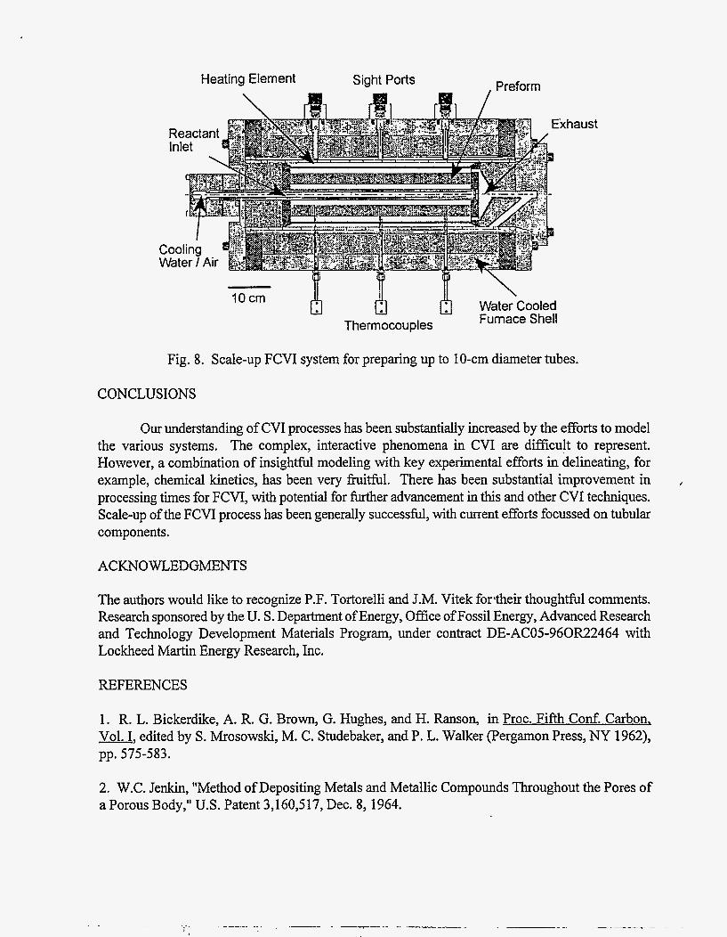
A furnace system for preparing 1 0-cm diameter tubular forms with 1-2 cm wall thickness and lengths of up to 45 cm has been designed and constructed (Fig. 8). The system contains a central, concentric, water-cooled reactant injector fixed along the centerline of a carbon-element resistance h a c e . The injector has a large number of penetrations to allow uniform flow of the reactants into the preform mandrel. The preform mandrel, which is positioned around the injector, allows for significant control of the thermal gradient. Although the mandrel will typically be constructed of graphite, there is allowance of emplacement of intervening material that would act as an insulator, or simply a plenum space which would serve as a thermal transport resistance. With the use of thermocouples the temperature profile can be obtained using a variety of insulatiodmandrel geometries to obtain the desired thermal gradient. At this time, the system is undergoing initial trials.
I
Heating Element Sight Ports
~
10 cm
Thermocouples
Preform
xh aust
\ Water Cooled Furnace Shell
Fig. 8. Scale-up FCVI system for preparing up to 10-cm diameter tubes.
CONCLUSIONS
Our understanding of CVI processes has been substantially increased by the efforts to model the various systems. The complex, interactive phenomena in CVI are difficult to represent. However, a combination of insightful modeling with key experimental efforts in delineating, for example, chemical kinetics, has been very fruitful. There has been substantial improvement in processing times for FCVI, with potential for further advancement in this and other CVI techniques. Scale-up of the FCVI process has been generally successfbl, with current efforts focussed on tubular components .
ACKNOWLEDGMENTS
The authors would like to recognize P.F. Tortorelli and J.M. Vitek for'their thoughtful comments. Research sponsored by the U. S. Department of Energy, Office of Fossil Energy, Advanced Research and Technology Development Materials Program, under contract DE-AC05-960R22464 with Lockheed Martin Energy Research, Inc.
REFERENCES
1. R. L. Bickerdike, A. R. G. Brown, G. Hughes, and H. Ranson, in Proc. Fifth Cod. Carbon, Vol. I, edited by S. Mrosowski, M. C. Studebaker, and P. L. Walker (Pergamon Press, NY 1962), pp. 575-583.
2. W.C. Jenkin, "Method of Depositing Metals and Metallic Compounds Throughout the Pores of a Porous Body," U.S. Patent 3,160,517, Dec. 8, 1964.

3. W.J. Lackey and T.L. Starr, in Fiber Reinforced Ceramic Composites, edited by K.S. Mazdiyasni (Noyes Publications, Park Ridge, NJ 1990), pp. 397-450.
4. E. Fitzer and R. Gadow, Am. Ceram. SOC. Bull. 65 [2], p. 326 (1986).
5. R. Naslain and F. Langlais, High Temp. Sci. 27, p. 221 (1990).
6. T.M. Besmann, B.W. Sheldon, R.A. Lowden, and D.P. Stinton, Science 253, p. 1104 (1991).
7. T.M. Besmann, R.A. Lowden, D.P. Stinton, J.C. McLaughlin, B.W. Sheldon, T.L. Stm, and A. W. Smith, Processing Science for Chemical Vapor Infiltration, Final Report, WL-TR-94-4044, U.S. Air Force Wright Laboratory, 1994.
8. Y.G. Roman and D.P. Stinton, in Ceramic Matrix Composites - Advanced High-Temuerature Structural Materials, edited by R.A. Lowden, M.K. Ferber, J.R. Hellmann, K.K. Chawla, and S.G. DiPietro (Mater. Res. SOC. Proc. 365, Pittsburgh, PA 1995), p.343-350.
9. T.M. Besmann and M.L. Johnson, in Proceedines of the International Symuosium on Ceramic Materials and Comuonents for Engines, edited by V.J. Tennery (Am, Ceram.Soc., Westerville, OH 1989), pp. 443-56.
10. T. M. Besmann, B.W. Sheldon, T.S. Moss 111, and M.D. Kaster, J. Am Ceram. SOC. 75 (101, p. 2899 (1992).
1 1. F. Loumagne, F. Langlais, and R. Naslain, J. de Physique IV 3, p. 527 (1 993).
12. D. Lespiaux, F. Langlais, R. Naslain, S. Schamm, and J. Sevely, J. Europ. Cer. SOC., p. 81 (1 995).
13. K. Brennfleck, E. Fitzer, G. Schoch, and M. Dietrich, in Proceedings of the Ninth International Conference on Chemical Vapor Deposition 1984, edited by McD. Robinson, C.H.J. van den Brekel, G.W. Cullen, J.M. Blocher, Jr., and P. Rai-Choudhury (Electrochem. SOC., Pennington, NJ 1984), pp. 649-55.
14. B.W. Sheldon and H.-C. Chang, Ceramic Trans. 42, p. 81 (1994).
15. G.B. Freeman, T.L. Starr and T.C. Elston, in Chemical Vapor Deposition of Refiactory Metals and Ceramics, edited by T.M. Besmann and B.M. Gallois (Mater. Res. SOC., Pittsburgh, PA 1990), pp. 49-54.
16. T.L. Starr, in Proceedings of the Tenth International Conference on Chemical Vapor Deposition -7 1987 edited by G.W. Cullen (Electrochem. SOC., Pennington, NJ 1987), pp.1147-55.
17. H.-C. Chang, T.F. Morse, and B.W. Sheldon, "Minimizing Infiltration Times During Isothermal Chemical Vapor Idiltration With Chlorosilanes," submitted to the J. Am. Ceram. SOC.
18. B.W. Sheldon and T.M. Besmann, J. Am. Ceram. SOC. 74 [12], p. 3046 (1991).
19. J.K. Kinney, T.M. Breunig, T.L. Starr, D. Haupt, M.C. Nichols, S.R. Stock, M.D. Butts, and R. A. Saroyan, Science 260, p. 789 (1993).
20. T. L. Starr, in Chemical Vauor Deuosition of Refractory Metals and Ceramics 11, edited by T.M. Besmann and B.M. Gallois (Mater. Res. SOC., Pittsburgh, PA 1992), pp. 207-14.
21. H.-C. Chang, T.F. Morse, and B.W. Sheldon, J. Materials Proc. and Manuf. Sci. 2, p. 437 (1 994).
22. T.L. Starr, J. Mat. Sci. 10 [9], p.1 (1995).
23. B.W. Sheldon, personal communication.
24. T.M. Besmann, J.C. McLaughlin, and T.L. Starr in Proceedings of the 18th Annual Conference on Composites and Advanced Materials-B, edited by K.V. Logan (Ceramic Engineering and Science Proceedings 15 [SI, Westerville, OH 1994), p. 897-907.

DISCLAIMER
This report was prepared as an account of work sponsored by an agency of the United States Government. Neither the United States Government nor any agency thereof, nor any of their employees, makes any warranty, express or implied. or assumes any legal liability or responsibility for the accuracy, completeness, or use- fulness of any information, apparatus, product, or process disclosed, or represents that its use would not infringe privately owned rights. Reference herein to any spe- cific commercial product, process, or service by trade name, trademark, manufac: turer, or otherwise does not necessarily constitute or imply its endorsement, recorn- mendation, or favoring by the United States Government or any agency thereof. The views and opinions of authors expressed herein do not necessarily state or reflect those of the United S ta tu Government or any agency thereof.